US10016291B2 - Self-expansible stent with radiopaque markers and method of making such a stent - Google Patents
Self-expansible stent with radiopaque markers and method of making such a stentDownload PDFInfo
- Publication number
- US10016291B2 US10016291B2US14/270,157US201414270157AUS10016291B2US 10016291 B2US10016291 B2US 10016291B2US 201414270157 AUS201414270157 AUS 201414270157AUS 10016291 B2US10016291 B2US 10016291B2
- Authority
- US
- United States
- Prior art keywords
- marker
- stent
- vertex
- vertexes
- markers
- Prior art date
- Legal status (The legal status is an assumption and is not a legal conclusion. Google has not performed a legal analysis and makes no representation as to the accuracy of the status listed.)
- Active, expires
Links
- 238000004519manufacturing processMethods0.000titledescription4
- 239000003550markerSubstances0.000claimsabstractdescription92
- 238000000034methodMethods0.000claimsdescription19
- 238000003466weldingMethods0.000claimsdescription8
- 229910052715tantalumInorganic materials0.000description11
- GUVRBAGPIYLISA-UHFFFAOYSA-Ntantalum atomChemical compound[Ta]GUVRBAGPIYLISA-UHFFFAOYSA-N0.000description11
- 239000000463materialSubstances0.000description9
- 229910001000nickel titaniumInorganic materials0.000description5
- 230000004323axial lengthEffects0.000description4
- 238000003698laser cuttingMethods0.000description4
- HZEWFHLRYVTOIW-UHFFFAOYSA-N[Ti].[Ni]Chemical compound[Ti].[Ni]HZEWFHLRYVTOIW-UHFFFAOYSA-N0.000description3
- 229910052751metalInorganic materials0.000description3
- 239000002184metalSubstances0.000description3
- 238000000926separation methodMethods0.000description3
- PXHVJJICTQNCMI-UHFFFAOYSA-NNickelChemical compound[Ni]PXHVJJICTQNCMI-UHFFFAOYSA-N0.000description2
- 230000004308accommodationEffects0.000description2
- 238000013459approachMethods0.000description2
- 210000004204blood vesselAnatomy0.000description2
- 239000012530fluidSubstances0.000description2
- 239000011159matrix materialSubstances0.000description2
- HLXZNVUGXRDIFK-UHFFFAOYSA-Nnickel titaniumChemical compound[Ti].[Ti].[Ti].[Ti].[Ti].[Ti].[Ti].[Ti].[Ti].[Ti].[Ti].[Ni].[Ni].[Ni].[Ni].[Ni].[Ni].[Ni].[Ni].[Ni].[Ni].[Ni].[Ni].[Ni].[Ni]HLXZNVUGXRDIFK-UHFFFAOYSA-N0.000description2
- 230000002093peripheral effectEffects0.000description2
- 230000005855radiationEffects0.000description2
- 229910001285shape-memory alloyInorganic materials0.000description2
- 230000002792vascularEffects0.000description2
- 206010073306Exposure to radiationDiseases0.000description1
- RTAQQCXQSZGOHL-UHFFFAOYSA-NTitaniumChemical compound[Ti]RTAQQCXQSZGOHL-UHFFFAOYSA-N0.000description1
- 230000002411adverseEffects0.000description1
- 229910045601alloyInorganic materials0.000description1
- 239000000956alloySubstances0.000description1
- 201000010099diseaseDiseases0.000description1
- 208000037265diseases, disorders, signs and symptomsDiseases0.000description1
- 238000009826distributionMethods0.000description1
- 238000009661fatigue testMethods0.000description1
- 239000012634fragmentSubstances0.000description1
- 230000006870functionEffects0.000description1
- 239000003292glueSubstances0.000description1
- PCHJSUWPFVWCPO-UHFFFAOYSA-NgoldChemical compound[Au]PCHJSUWPFVWCPO-UHFFFAOYSA-N0.000description1
- 229910052737goldInorganic materials0.000description1
- 239000010931goldSubstances0.000description1
- 238000003384imaging methodMethods0.000description1
- 238000002513implantationMethods0.000description1
- 150000002739metalsChemical class0.000description1
- 229910052759nickelInorganic materials0.000description1
- 231100000252nontoxicToxicity0.000description1
- 230000003000nontoxic effectEffects0.000description1
- 230000001376precipitating effectEffects0.000description1
- 230000001105regulatory effectEffects0.000description1
- 229910002058ternary alloyInorganic materials0.000description1
- 239000010936titaniumSubstances0.000description1
- 229910052719titaniumInorganic materials0.000description1
Images


Classifications
- A—HUMAN NECESSITIES
- A61—MEDICAL OR VETERINARY SCIENCE; HYGIENE
- A61F—FILTERS IMPLANTABLE INTO BLOOD VESSELS; PROSTHESES; DEVICES PROVIDING PATENCY TO, OR PREVENTING COLLAPSING OF, TUBULAR STRUCTURES OF THE BODY, e.g. STENTS; ORTHOPAEDIC, NURSING OR CONTRACEPTIVE DEVICES; FOMENTATION; TREATMENT OR PROTECTION OF EYES OR EARS; BANDAGES, DRESSINGS OR ABSORBENT PADS; FIRST-AID KITS
- A61F2/00—Filters implantable into blood vessels; Prostheses, i.e. artificial substitutes or replacements for parts of the body; Appliances for connecting them with the body; Devices providing patency to, or preventing collapsing of, tubular structures of the body, e.g. stents
- A61F2/82—Devices providing patency to, or preventing collapsing of, tubular structures of the body, e.g. stents
- A61F2/86—Stents in a form characterised by the wire-like elements; Stents in the form characterised by a net-like or mesh-like structure
- A61F2/90—Stents in a form characterised by the wire-like elements; Stents in the form characterised by a net-like or mesh-like structure characterised by a net-like or mesh-like structure
- A61F2/91—Stents in a form characterised by the wire-like elements; Stents in the form characterised by a net-like or mesh-like structure characterised by a net-like or mesh-like structure made from perforated sheets or tubes, e.g. perforated by laser cuts or etched holes
- A61F2/915—Stents in a form characterised by the wire-like elements; Stents in the form characterised by a net-like or mesh-like structure characterised by a net-like or mesh-like structure made from perforated sheets or tubes, e.g. perforated by laser cuts or etched holes with bands having a meander structure, adjacent bands being connected to each other
- A61F2002/9155—Adjacent bands being connected to each other
- A61F2002/91558—Adjacent bands being connected to each other connected peak to peak
- A—HUMAN NECESSITIES
- A61—MEDICAL OR VETERINARY SCIENCE; HYGIENE
- A61F—FILTERS IMPLANTABLE INTO BLOOD VESSELS; PROSTHESES; DEVICES PROVIDING PATENCY TO, OR PREVENTING COLLAPSING OF, TUBULAR STRUCTURES OF THE BODY, e.g. STENTS; ORTHOPAEDIC, NURSING OR CONTRACEPTIVE DEVICES; FOMENTATION; TREATMENT OR PROTECTION OF EYES OR EARS; BANDAGES, DRESSINGS OR ABSORBENT PADS; FIRST-AID KITS
- A61F2230/00—Geometry of prostheses classified in groups A61F2/00 - A61F2/26 or A61F2/82 or A61F9/00 or A61F11/00 or subgroups thereof
- A61F2230/0002—Two-dimensional shapes, e.g. cross-sections
- A61F2230/0004—Rounded shapes, e.g. with rounded corners
- A61F2230/0013—Horseshoe-shaped, e.g. crescent-shaped, C-shaped, U-shaped
- A—HUMAN NECESSITIES
- A61—MEDICAL OR VETERINARY SCIENCE; HYGIENE
- A61F—FILTERS IMPLANTABLE INTO BLOOD VESSELS; PROSTHESES; DEVICES PROVIDING PATENCY TO, OR PREVENTING COLLAPSING OF, TUBULAR STRUCTURES OF THE BODY, e.g. STENTS; ORTHOPAEDIC, NURSING OR CONTRACEPTIVE DEVICES; FOMENTATION; TREATMENT OR PROTECTION OF EYES OR EARS; BANDAGES, DRESSINGS OR ABSORBENT PADS; FIRST-AID KITS
- A61F2250/00—Special features of prostheses classified in groups A61F2/00 - A61F2/26 or A61F2/82 or A61F9/00 or A61F11/00 or subgroups thereof
- A61F2250/0058—Additional features; Implant or prostheses properties not otherwise provided for
- A61F2250/0096—Markers and sensors for detecting a position or changes of a position of an implant, e.g. RF sensors, ultrasound markers
- A61F2250/0098—Markers and sensors for detecting a position or changes of a position of an implant, e.g. RF sensors, ultrasound markers radio-opaque, e.g. radio-opaque markers
- Y—GENERAL TAGGING OF NEW TECHNOLOGICAL DEVELOPMENTS; GENERAL TAGGING OF CROSS-SECTIONAL TECHNOLOGIES SPANNING OVER SEVERAL SECTIONS OF THE IPC; TECHNICAL SUBJECTS COVERED BY FORMER USPC CROSS-REFERENCE ART COLLECTIONS [XRACs] AND DIGESTS
- Y10—TECHNICAL SUBJECTS COVERED BY FORMER USPC
- Y10T—TECHNICAL SUBJECTS COVERED BY FORMER US CLASSIFICATION
- Y10T29/00—Metal working
- Y10T29/49—Method of mechanical manufacture
- Y10T29/49826—Assembling or joining
Definitions
- This inventionrelates to a radially self-expansible stent with a plurality of radiopaque markers attached to at least one of its ends, and to a method of making such a stent.
- Vascular stentsare commonly used for the treatment of various vessel diseases. They are implanted transluminally using a catheter delivery system, to advance them to a stenting site, where they expand in order to widen the clogged or narrowed blood vessel. During the implantation procedure, the exact position of the stent within the vessel is monitored, mainly using X-ray imaging techniques. In order to ensure accurate placement, a good visibility of the stent is crucial. In general, this is achieved by attaching suitable markers which are made from materials with a radiopacity larger than that of the stent material. In addition, these markers have to be sufficiently large to provide a good X-ray contrast. For a precise determination of the stent position during delivery, it is advantageous to place the markers at both ends of the stent.
- a tubular stent with a plurality of radiopaque markers attached to selected inflection zones around its circumferenceis disclosed in WO 2002/015820.
- the markersare spoon-shaped in a way that almost a complete ring of marker material is formed in the radially compressed state of the stent, providing a particularly high level of radiopacity during transluminal delivery.
- an increase in visibility to radiationis achieved without any increase in the wall thickness of the stent at the position of the markers, maintaining a large radial opening for fluid flow as well as a small cross-sectional profile.
- the number of markers in such a ring of markers as described aboveis to be kept small, so that each marker is large enough to facilitate sufficient visibility even in the radially expanded state of the stent.
- the number of marker/inflection zone jointsshould be kept at a minimum in order to reduce the risk of loss of a marker in the body following failure of such a joint after the stent has been placed.
- stent delivery to the narrowed portion of the blood vesselis performed with the use of a co-axial catheter delivery system.
- the stentis kept in its radially compressed state by an outer sheath.
- a co-axial cylinder inside the sheathis used for displacing the stent axially, relative to the outer sheath.
- WO 2006/047977discloses a stent with an end annulus that carries radiopaque marker material in recesses in receiving elements of the stent metal.
- the marker materialhas exposed luminal and abluminal part-cylindrical opposed major surfaces and a thickness corresponding to that of the receiving element that surrounds the entire peripheral edge of the marker between its major surfaces.
- the markerhas a width in the circumferential direction of the stent annulus, that is smaller than the circumferential length of the portion of the stent in which the marker is received.
- the markerenters the recess from a position radially outside the stent annulus, conical surface portions of the marker and the receiving portion serving to guide the marker into a snugly fitting disposition within the receiving portion, supported in all sides by the receiving portion.
- EP 1 433 438discloses other sorts of radiopaque markers on stents, notably a wire of radiopaque material wound around a strut of the stent, or a sleeve of radiopaque material crimped around a strut of the stent.
- the stentis locally thicker in the radial direction, where such markers are located.
- the main objective of the present inventionis to provide a self-expansible stent with radiopaque markers attached to it that offers a high degree of mechanical stability during release of the stent from the delivery system while maintaining a good visibility upon exposure to radiation.
- This aimis achieved by a self-expansible stent with the technical features of claim 1 .
- Preferred embodiments of the inventionfollow from the subclaims.
- the present inventionprovides a radially self-expansible stent with two end annuli for delivery by a co-axial catheter delivery system.
- the end annulus to be pushed during release of the stenthas a plurality of spaced inflection zones distributed in its circumference, some of which carry a radiopaque marker.
- the ideais to get all the inflection zones to share the release stresses, not just the ones that carry a radiopaque marker.
- the term “inflection zone” as used hereinrefers to a region where two or more strut ends are connected or where two or more struts intersect. It is, however, not restricted to this interpretation.
- a large number of different strut patternsare being used, or have at least been proposed, for tubular stents. Each of these patterns will have points which define an end to the stent tube and which allow for the attachment of a marker. Our definition of the term “inflection zone” is such that these end points are included.
- the radiopaque markersare shaped and located on the selected inflection zones such that the compressive stress exerted on the end annulus during release of the stent is shared between the markers and the inflection zones that do not carry a marker. In this way, the strain on the marker/inflection zone joints is minimised, reducing the risk of physical damage, such as breakage or deformation.
- This conceptis applicable to any stent design and allows for the use of only a small number of markers while the stability of the stent is secured. Keeping the number of markers at a minimum has significant advantages. First, having fewer marker/inflection zone joints reduces the danger of severed or bent markers. Self-expansible stents are extremely elastic but nevertheless not invulnerable to distortion.
- Fatigue performanceis of vital importance with vascular stents, which flex with every heartbeat. Any stress that a stent matrix suffers locally, that exceeds the maximum planned for in the Government regulatory fatigue-testing protocol can adversely affect the fatigue life of the stent. This fact emphasizes the importance of a robust stent design, since even the slightest damage to the joints occurring during the release of the stent may shorten the service life of the stent. Furthermore, the circumference of the ring formed by the ensemble of markers in the radially compressed state of the stent is limited by the circumference of the stent tube itself. Thus, keeping the number of markers small allows for larger marker sizes and consequently an improved visibility of the stent in the radially expanded state.
- ring stentsexhibit a plurality of rings arranged along their axial length which are interconnected between ring ends and have a plurality of inflection zones distributed in the circumference of the ring ends.
- each of these ring endscomprises more inflection zones than the end annulus of the stent. Since, in the radially compressed state, the stent has a homogeneous circumference throughout its structure, the circumference of the end annulus of the stent will be the same as that of the ring ends, despite comprising less inflection zones. Therefore, the circumferential extent of the inflection zones that carry a marker can be increased, allowing for the attachment of larger markers, which is advantageous for reasons of visibility as discussed above.
- the above arrangementfacilitates a possible increase in marker size without changing the number of inflection zones of the stent rings which may affect the mechanical properties of the stent, such as stability and elasticity.
- a further way of creating more space for the markers within the end annulus of the stentis given in another preferred embodiment, where the inflection zones of the end annulus of the stent that do not carry a marker have a larger axial length parallel to the long axis of the stent than the inflection zones distributed in the circumference of the ring ends.
- the markersare bonded to the inflection zones at a glue interface, more preferably, by a weld.
- the form of the weldis hereby determined by the shape and the size of the marker.
- the inflection zones that carry a markerdiffer in shape, size or both shape and size from the inflection zones that do not carry a marker.
- the inflection zones that carry a markermay, for example, have a smaller size so as to leave more space for the attached markers or a shape particularly suited for a certain type of weld (depending on the shape and size of the marker).
- each inflection zoneis present as a stem with an axial length parallel to the long axis of the stent.
- the inflection zone stems that carry a markerhave a smaller length than the inflection zone stems that do not carry a marker. This arrangement allows for the accommodation of portions of the markers (or even whole markers) between the neighbouring longer inflection zones.
- the markers and the inflection zoneshave the same thickness but markers with a greater radial thickness are not excluded.
- an increase in marker thickness beyond the stent annulus wall thicknessis not desirable, since a large radial opening for fluid flow as well as a small cross-sectional profile of the stent ought to be maintained.
- both the radiopacity and the mechanical properties of the markersdepend on their thickness. Consequently, too thin a marker will give a poor contrast when exposed to radiation and may be prone to deformation or even breakage.
- each markersubtends a larger arc of the circumference of the end annulus than each inflection zone that does not carry a marker, improving the visibility of the stent ends.
- the width of the marker, in the circumferential directionwill generally be as larges as, or larger than, but not smaller than, the circumferential width of the inflection zone to which the marker is attached.
- the stentis made from a nickel titanium shape memory alloy.
- a nickel titanium shape memory alloyprovides the mechanical properties necessary for reliable stent operation, namely a high degree of elasticity and physical stability.
- the radiopaque markersare preferably made from tantalum, gold, or a ternary alloy made from nickel, titanium and a third, radiopaque metal. All these metals offer a high level of radiopacity. Both the above stent and marker materials are non-toxic and provide a good biological compatibility with the human body. For nickel titanium stents, markers of tantalum are of special interest because their electrochemical potentials are so similar.
- the markersdo not extend axially beyond the inflection zones which do not carry a marker, in the radially compressed state of the stent.
- This arrangementcan be accomplished, for example, by making the inflection zones that carry a marker shorter than the ones that do not carry a marker.
- both the markers and the inflection zones which do not carry a markerabut, or are otherwise in physical contact with, the pushing part of the delivery system, i.e., the co-axial inner cylinder.
- the compressive stress exerted on the end annulus during release of the stentis shared between the markers and the inflection zones without markers, minimising the risk of physical damage to the stent.
- a marker size large enough for excellent visibilitycan still be maintained by choosing a small number of inflection zones in the end annulus of the stent and by making the inflection zones that carry a marker sufficiently short.
- portions of the periphery of the markersrest on the neighbouring inflection zones in the radially compressed state of the stent, such that the compressive stress exerted by the delivery system on the markers during release of the stent is delivered to the neighbouring inflection zones by the markers.
- the markersstand axially proud of the inflection zones that do not carry a marker. In this configuration, an increase in marker size can be achieved, while the distribution of the applied pressure between markers and inflection zones without markers is still maintained.
- the markerscan be welded to the inflection zones by methods described in above-mentioned WO 2002/015820.
- the markers and inflection zonescan be advanced towards each other along the longitudinal axis of the stent without any relative radial movement, for example by providing a form fit between the respective marker and inflection zone faces that face each other across the welding zone.
- the form fitcan be accomplished by co-operating ramp surfaces on the marker and the inflection zone, that work together to inhibit any relative circumferential sliding movement in the width direction of the marker and inflection zone. In this way, the markers are guided into a position circumferentially aligned with the respective inflection zone, prior to being welded to that inflection zone.
- FIG. 1shows a laser cutting of a stent with radiopaque markers attached to it, according to a first preferred embodiment
- FIG. 2shows one end of a laser cutting of a stent with radiopaque markers attached to it, according to a second preferred embodiment
- FIG. 3shows a portion of the end annulus in the radially expanded state of the stent, according to a second preferred embodiment
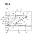
- FIG. 4is a view of a fragment of one end of a stent, that shows an inflection zone comprising a marker and flanked by longer inflection zones that do not carry any marker.
- FIG. 1shows a laser cutting of a radially self-expansible stent 10 made from Nitinol with radiopaque markers 14 made from Tantalum attached, according to a first preferred embodiment.
- the markers 14are welded to the inflection zones 12 ′ and extend as far as the inflection zones that do not carry a marker 12 .
- the compressive stress exerted on the end annulus 11 by a stent pusher annulus P during release of the stentis shared between the markers 14 and the inflection zones 12 that do not carry a marker because what abuts the pusher P is not just the markers 14 but also the inflection zones 12 that carry no marker 14 .
- the stentcomprises four interconnected rings 16 with fourteen inflection zones 12 ′′ in the circumference of each ring end.
- the end annuli 11 , 11 ′only have twelve inflection zones 12 , 12 ′. This allows for a larger circumferential extent of the inflection zones 12 ′ and the markers 14 attached thereto since the circumferential extent of the inflection zones 12 is identical to that of the inflection zones 12 ′′.
- the axial length of inflection zones 12is larger than that of inflection zones 12 ′′, allowing for longer markers.
- the present embodimentis specifically designed for accommodating large markers 14 in order to optimise the visibility of the stent 10 .
- FIG. 2shows one end of a laser cutting of a stent 10 made from Nitinol with radiopaque markers 14 made from Tantalum attached to it, according to a second preferred embodiment.
- the markers 14are welded to the inflection zones 12 ′ and stand axially proud of the inflection zones 12 that do not carry a marker 14 .
- the shape of inflection zones 12 ′is adapted in order to allow for a robust welded connection with marker 14 and differs significantly from that of inflection zones 12 .
- inflection zones 12 ′as compared to inflection zones 12 is facilitated by the difference in the number of inflection zones 12 , 12 ′, 12 ′′ between the ends of rings 16 and the end annulus 11 , analogous to the first preferred embodiment.
- inflection zones 12have grooves 18 at their top ends which are shaped to accommodate the peripheral portions of the T-shaped markers 14 in the radially compressed state of the stent 10 . In this way, despite the fact that during the release of the stent 10 only the markers 14 are in physical contact with the pushing part P of the delivery system, the compressive stress exerted on the markers is shared between the markers and the neighbouring inflection zones.
- FIG. 3shows a portion of the end annulus 11 in the radially expanded state of the stent 10 , according to the present embodiment. Here, the grooves 18 are more clearly visible.
- FIG. 4here we see a tantalum marker 14 located between two long inflection zones 12 and to be welded to a short inflection zone 12 ′.
- the markeris joined by two small bridges 48 , 50 to a tantalum tube 40 .
- These bridges 48 , 50facilitate separation of the marker 14 from the tantalum tube 40 in an uncomplicated manner by the application of an external force, once the welding has been performed.
- the bridges 48 , 50are not a required feature and other methods may be applied for separating the marker 14 from the tantalum tube 40 .
- a single lasermay be used for both welding the marker 14 to the inflection zone 12 ′ and separating the marker 14 from the tantalum tube 40 .
- the welding stepis performed and subsequently the separation step is carried out after increasing the output power of the laser. Both these steps can be carried out in a single operation, thus improving the efficiency of the fabrication process.
- the connection profile between tantalum tube 40 and marker 14may be of any conceivable form, for example, a single wider bridge.
- the tantalum tube 40 and the tube of nickel titanium shape memory alloy of the stent and the inflection zones 12are approximated axially, whereupon the facing surfaces 20 and 22 of the inflection zone 12 and marker 14 come into facing relationship, ready for welding together.
- axial approachthere is no need for any relative radial movements between the two work pieces.
- the facing surfaces 20 , 22achieve a circumferential guiding function through a mechanical “form fit”. As the nose 70 of the marker 14 approaches the inflection zone 12 ′ it can slide along the facing surface 20 until it goes past the axially aligned straight edge 24 when straight edge 26 of the nose 70 will then be facing the straight edge 24 .
- the V-shaped recess in the facing surface 22 of the markerflanked by reverse-angled surface 30 , will have received the V-shaped peak in the facing surface 20 of the inflection zone 12 ′ flanked by reverse-angled surface portion 28 in the facing surface 20 . Any widening in the gap between surfaces 24 and 26 is prevented by the abutment of surfaces 28 and 30 (and vice versa). In this way, the marker 14 , approximated to the inflection zone 12 ′ and ready for welding to it, has no freedom any more to move circumferentially relative to the inflection zone 12 ′.
- the end surface 56 of the marker 14lies in the same plane, transverse to the axis of the stent, as the end surfaces 52 and 54 of the flanking inflection zones 12 .
- the pushing forceis imposed equally on all of end surfaces 52 , 54 and 56 .
Landscapes
- Health & Medical Sciences (AREA)
- Engineering & Computer Science (AREA)
- Biomedical Technology (AREA)
- Heart & Thoracic Surgery (AREA)
- Life Sciences & Earth Sciences (AREA)
- Cardiology (AREA)
- Oral & Maxillofacial Surgery (AREA)
- Transplantation (AREA)
- Veterinary Medicine (AREA)
- Vascular Medicine (AREA)
- Public Health (AREA)
- Animal Behavior & Ethology (AREA)
- General Health & Medical Sciences (AREA)
- Optics & Photonics (AREA)
- Physics & Mathematics (AREA)
- Media Introduction/Drainage Providing Device (AREA)
- Prostheses (AREA)
- Materials For Medical Uses (AREA)
Abstract
Description
This application is a division of U.S. patent application Ser. No. 12/676,584, now U.S. Pat. No. 8,721,709, which was filed as a U.S. national stage application under 35 USC § 371 of International Application No. PCT/EP2008/061775, filed Sep. 5, 2008, which claims priority to United Kingdom Patent Application No. 0717481.6, filed Sep. 7, 2007, each of which is incorporated by reference in its entirety into this application.
This invention relates to a radially self-expansible stent with a plurality of radiopaque markers attached to at least one of its ends, and to a method of making such a stent.
Vascular stents are commonly used for the treatment of various vessel diseases. They are implanted transluminally using a catheter delivery system, to advance them to a stenting site, where they expand in order to widen the clogged or narrowed blood vessel. During the implantation procedure, the exact position of the stent within the vessel is monitored, mainly using X-ray imaging techniques. In order to ensure accurate placement, a good visibility of the stent is crucial. In general, this is achieved by attaching suitable markers which are made from materials with a radiopacity larger than that of the stent material. In addition, these markers have to be sufficiently large to provide a good X-ray contrast. For a precise determination of the stent position during delivery, it is advantageous to place the markers at both ends of the stent.
A tubular stent with a plurality of radiopaque markers attached to selected inflection zones around its circumference is disclosed in WO 2002/015820. The markers are spoon-shaped in a way that almost a complete ring of marker material is formed in the radially compressed state of the stent, providing a particularly high level of radiopacity during transluminal delivery. Thereby, an increase in visibility to radiation is achieved without any increase in the wall thickness of the stent at the position of the markers, maintaining a large radial opening for fluid flow as well as a small cross-sectional profile. Ideally, the number of markers in such a ring of markers as described above is to be kept small, so that each marker is large enough to facilitate sufficient visibility even in the radially expanded state of the stent. Furthermore, the number of marker/inflection zone joints should be kept at a minimum in order to reduce the risk of loss of a marker in the body following failure of such a joint after the stent has been placed.
For the case of self-expansible stents, delivery to the narrowed portion of the blood vessel is performed with the use of a co-axial catheter delivery system. Hereby, the stent is kept in its radially compressed state by an outer sheath. A co-axial cylinder inside the sheath is used for displacing the stent axially, relative to the outer sheath. Once the stent has been placed at the desired position within the vessel, the outer sheath is withdrawn while the inner cylinder pushes against one end of the compressed stent, precipitating the release of the stent from the delivery system. This procedure can impose on a stent such as the one disclosed in WO 2002/015820 stresses concentrated on the radiopaque markers which protrude axially beyond the axial end of the matrix of struts of the stent annulus. This stress, concentrating at the joints between the markers and the inflection zones from which they are cantilevered, has been identified by the present inventor as a feature that can and should be reduced or even eliminated.
This patent application declares the priority of GB 0 717 481.6. In that GB priority application the search report conducted on the claims by the UK Patent Office cited the following documents: WO 2006/047977;DE 20 2004 014 789; WO 2004/028408 and EP 1 433 438. The disclosures of the first two citations are of the same invention from the same inventor.
WO 2006/047977 discloses a stent with an end annulus that carries radiopaque marker material in recesses in receiving elements of the stent metal. Thus, the marker material has exposed luminal and abluminal part-cylindrical opposed major surfaces and a thickness corresponding to that of the receiving element that surrounds the entire peripheral edge of the marker between its major surfaces. The marker has a width in the circumferential direction of the stent annulus, that is smaller than the circumferential length of the portion of the stent in which the marker is received. The marker enters the recess from a position radially outside the stent annulus, conical surface portions of the marker and the receiving portion serving to guide the marker into a snugly fitting disposition within the receiving portion, supported in all sides by the receiving portion.
The disclosure of WO 2004/028408 is similar. As to EP 1 433 438, it discloses other sorts of radiopaque markers on stents, notably a wire of radiopaque material wound around a strut of the stent, or a sleeve of radiopaque material crimped around a strut of the stent. Self-evidently, the stent is locally thicker in the radial direction, where such markers are located.
The main objective of the present invention is to provide a self-expansible stent with radiopaque markers attached to it that offers a high degree of mechanical stability during release of the stent from the delivery system while maintaining a good visibility upon exposure to radiation. This aim is achieved by a self-expansible stent with the technical features of claim1. Preferred embodiments of the invention follow from the subclaims.
The present invention provides a radially self-expansible stent with two end annuli for delivery by a co-axial catheter delivery system. The end annulus to be pushed during release of the stent has a plurality of spaced inflection zones distributed in its circumference, some of which carry a radiopaque marker. The idea is to get all the inflection zones to share the release stresses, not just the ones that carry a radiopaque marker. In general, the term “inflection zone” as used herein refers to a region where two or more strut ends are connected or where two or more struts intersect. It is, however, not restricted to this interpretation. A large number of different strut patterns are being used, or have at least been proposed, for tubular stents. Each of these patterns will have points which define an end to the stent tube and which allow for the attachment of a marker. Our definition of the term “inflection zone” is such that these end points are included.
The radiopaque markers are shaped and located on the selected inflection zones such that the compressive stress exerted on the end annulus during release of the stent is shared between the markers and the inflection zones that do not carry a marker. In this way, the strain on the marker/inflection zone joints is minimised, reducing the risk of physical damage, such as breakage or deformation. This concept is applicable to any stent design and allows for the use of only a small number of markers while the stability of the stent is secured. Keeping the number of markers at a minimum has significant advantages. First, having fewer marker/inflection zone joints reduces the danger of severed or bent markers. Self-expansible stents are extremely elastic but nevertheless not invulnerable to distortion. Fatigue performance is of vital importance with vascular stents, which flex with every heartbeat. Any stress that a stent matrix suffers locally, that exceeds the maximum planned for in the Government regulatory fatigue-testing protocol can adversely affect the fatigue life of the stent. This fact emphasizes the importance of a robust stent design, since even the slightest damage to the joints occurring during the release of the stent may shorten the service life of the stent. Furthermore, the circumference of the ring formed by the ensemble of markers in the radially compressed state of the stent is limited by the circumference of the stent tube itself. Thus, keeping the number of markers small allows for larger marker sizes and consequently an improved visibility of the stent in the radially expanded state.
So-called “ring stents” exhibit a plurality of rings arranged along their axial length which are interconnected between ring ends and have a plurality of inflection zones distributed in the circumference of the ring ends. In one embodiment, each of these ring ends comprises more inflection zones than the end annulus of the stent. Since, in the radially compressed state, the stent has a homogeneous circumference throughout its structure, the circumference of the end annulus of the stent will be the same as that of the ring ends, despite comprising less inflection zones. Therefore, the circumferential extent of the inflection zones that carry a marker can be increased, allowing for the attachment of larger markers, which is advantageous for reasons of visibility as discussed above. Even more space for the markers can be created within the end annulus of the stent if the inflection zones of the end annulus of the stent that do not carry a marker have a smaller circumferential extent than the inflection zones distributed in the circumference of the ring ends. Therefore, the above arrangement facilitates a possible increase in marker size without changing the number of inflection zones of the stent rings which may affect the mechanical properties of the stent, such as stability and elasticity.
A further way of creating more space for the markers within the end annulus of the stent is given in another preferred embodiment, where the inflection zones of the end annulus of the stent that do not carry a marker have a larger axial length parallel to the long axis of the stent than the inflection zones distributed in the circumference of the ring ends.
Preferably, the markers are bonded to the inflection zones at a glue interface, more preferably, by a weld. The form of the weld is hereby determined by the shape and the size of the marker.
In a preferred embodiment, the inflection zones that carry a marker differ in shape, size or both shape and size from the inflection zones that do not carry a marker. The inflection zones that carry a marker may, for example, have a smaller size so as to leave more space for the attached markers or a shape particularly suited for a certain type of weld (depending on the shape and size of the marker). In one embodiment, each inflection zone is present as a stem with an axial length parallel to the long axis of the stent. Preferably, the inflection zone stems that carry a marker have a smaller length than the inflection zone stems that do not carry a marker. This arrangement allows for the accommodation of portions of the markers (or even whole markers) between the neighbouring longer inflection zones.
Preferably, the markers and the inflection zones have the same thickness but markers with a greater radial thickness are not excluded. On the one hand, an increase in marker thickness beyond the stent annulus wall thickness is not desirable, since a large radial opening for fluid flow as well as a small cross-sectional profile of the stent ought to be maintained. On the other hand, both the radiopacity and the mechanical properties of the markers depend on their thickness. Consequently, too thin a marker will give a poor contrast when exposed to radiation and may be prone to deformation or even breakage.
In a preferred embodiment, each marker subtends a larger arc of the circumference of the end annulus than each inflection zone that does not carry a marker, improving the visibility of the stent ends. In any event, the width of the marker, in the circumferential direction, will generally be as larges as, or larger than, but not smaller than, the circumferential width of the inflection zone to which the marker is attached.
A number of different materials may be used for the fabrication of the stent and the radiopaque markers. Preferably, the stent is made from a nickel titanium shape memory alloy. Such an alloy provides the mechanical properties necessary for reliable stent operation, namely a high degree of elasticity and physical stability. The radiopaque markers are preferably made from tantalum, gold, or a ternary alloy made from nickel, titanium and a third, radiopaque metal. All these metals offer a high level of radiopacity. Both the above stent and marker materials are non-toxic and provide a good biological compatibility with the human body. For nickel titanium stents, markers of tantalum are of special interest because their electrochemical potentials are so similar.
In another preferred embodiment, the markers do not extend axially beyond the inflection zones which do not carry a marker, in the radially compressed state of the stent. This arrangement can be accomplished, for example, by making the inflection zones that carry a marker shorter than the ones that do not carry a marker. Preferably, during release of the stent from the delivery system, both the markers and the inflection zones which do not carry a marker abut, or are otherwise in physical contact with, the pushing part of the delivery system, i.e., the co-axial inner cylinder. In such a configuration, the compressive stress exerted on the end annulus during release of the stent is shared between the markers and the inflection zones without markers, minimising the risk of physical damage to the stent. A marker size large enough for excellent visibility can still be maintained by choosing a small number of inflection zones in the end annulus of the stent and by making the inflection zones that carry a marker sufficiently short.
In another preferred embodiment, portions of the periphery of the markers rest on the neighbouring inflection zones in the radially compressed state of the stent, such that the compressive stress exerted by the delivery system on the markers during release of the stent is delivered to the neighbouring inflection zones by the markers. Preferably, in this configuration the markers stand axially proud of the inflection zones that do not carry a marker. In this configuration, an increase in marker size can be achieved, while the distribution of the applied pressure between markers and inflection zones without markers is still maintained.
The markers can be welded to the inflection zones by methods described in above-mentioned WO 2002/015820. In a variation, however, the markers and inflection zones can be advanced towards each other along the longitudinal axis of the stent without any relative radial movement, for example by providing a form fit between the respective marker and inflection zone faces that face each other across the welding zone. The form fit can be accomplished by co-operating ramp surfaces on the marker and the inflection zone, that work together to inhibit any relative circumferential sliding movement in the width direction of the marker and inflection zone. In this way, the markers are guided into a position circumferentially aligned with the respective inflection zone, prior to being welded to that inflection zone.
Turning toFIG. 4 , here we see atantalum marker 14 located between twolong inflection zones 12 and to be welded to ashort inflection zone 12′. The marker is joined by twosmall bridges tantalum tube 40. Thesebridges marker 14 from thetantalum tube 40 in an uncomplicated manner by the application of an external force, once the welding has been performed. However, thebridges marker 14 from thetantalum tube 40. In particular, a single laser may be used for both welding themarker 14 to theinflection zone 12′ and separating themarker 14 from thetantalum tube 40. In this case, first the welding step is performed and subsequently the separation step is carried out after increasing the output power of the laser. Both these steps can be carried out in a single operation, thus improving the efficiency of the fabrication process. If the above described separation method is used, the connection profile betweentantalum tube 40 andmarker 14 may be of any conceivable form, for example, a single wider bridge. As explained in WO 2002/015820 mentioned above, thetantalum tube 40 and the tube of nickel titanium shape memory alloy of the stent and theinflection zones 12 are approximated axially, whereupon the facing surfaces20 and22 of theinflection zone 12 andmarker 14 come into facing relationship, ready for welding together. The skilled reader will appreciate that during this approximation by axial approach there is no need for any relative radial movements between the two work pieces.
As to circumferential alignment between themarker 14 and theinflection zone 12, we see inFIG. 4 how the facing surfaces20,22 incorporate formfit portions marker 14 into alignment with the inflection zone so there isclearance marker 14 and the two flankinginflection zones 12, respectively.
The facing surfaces20,22 achieve a circumferential guiding function through a mechanical “form fit”. As thenose 70 of themarker 14 approaches theinflection zone 12′ it can slide along the facingsurface 20 until it goes past the axially alignedstraight edge 24 whenstraight edge 26 of thenose 70 will then be facing thestraight edge 24.
By then, however, the V-shaped recess in the facingsurface 22 of the marker, flanked by reverse-angledsurface 30, will have received the V-shaped peak in the facingsurface 20 of theinflection zone 12′ flanked by reverse-angledsurface portion 28 in the facingsurface 20. Any widening in the gap betweensurfaces surfaces 28 and30 (and vice versa). In this way, themarker 14, approximated to theinflection zone 12′ and ready for welding to it, has no freedom any more to move circumferentially relative to theinflection zone 12′. Exactly in this “welding ready” disposition, theend surface 56 of themarker 14 lies in the same plane, transverse to the axis of the stent, as the end surfaces52 and54 of the flankinginflection zones 12. Thus, when the stent is pushed by a pusher P, the pushing force is imposed equally on all of end surfaces52,54 and56.
The illustrated embodiments are by way of example and the skilled reader will appreciate that features can be isolated from one embodiment and can be taken and used in other embodiments within the scope of the claims which follow.
Claims (14)
1. A method of fastening a radiopaque marker to an A-vertex of a radially self-expanding stent, in which the marker is advanced into a fastening position and then welded to the A-vertex creating a welding zone between the A-vertex and the marker, wherein:
the relative movement between the marker and the A-vertex lacks a component orthogonal to the stent's longitudinal axis, and
an end surface of the marker and end surfaces of B-vertexes that circumferentially flank the marker and the A-vertex all lie in a plane orthogonal to the longitudinal axis.
2. The method ofclaim 1 , wherein the marker and the A-vertex fit to inhibit circumferential sliding movement.
3. The method ofclaim 2 , wherein ramp surfaces on the marker and the A-vertex cooperate to circumferentially align the marker and the A-vertex.
4. The method ofclaim 3 , wherein the end surface of the marker and the end surfaces of the B-vertexes define an end of a stent and markers object.
5. The method ofclaim 4 , wherein the B-vertexes comprise two, intersected strut ends, the strut ends being circumferentially offset from the marker such that lateral surface of the marker faces a lateral surface of at least one of the strut ends.
6. The method ofclaim 5 , wherein the A-vertex has a shape different from the B-vertexes.
7. The method ofclaim 6 , wherein the B-vertexes comprise a portion shaped to correspond to a portion of the marker.
8. The method ofclaim 7 , wherein the A-vertex has a size different from the B-vertexes.
9. A method comprising:
providing a radiopaque marker;
providing a self-expanding stent comprising an A-vertex positioned between two circumferentially arranged, B-vertexes;
and
advancing the marker into a fastening position abutting the A-vertex, until a marker end and ends of the two B-vertexes all lie in a plane orthogonal to a longitudinal axis of the stent,
wherein advancing is with longitudinal movement and without radial movement.
10. The method ofclaim 9 , wherein at least one of the B-vertexes comprises two, intersecting strut ends that abut the marker, are circumferentially offset from the marker, and have a contour matching the marker's abutting contour.
11. The method ofclaim 10 , wherein the A-vertex has a shape different from the B-vertexes.
12. The method ofclaim 11 , wherein at least one of the B-vertexes comprises a portion shaped to correspond to a portion of the marker.
13. The method ofclaim 12 , wherein the A-vertex has a size different from the B-vertexes.
14. The method ofclaim 13 , wherein the marker further comprises a tongue that engages an elongated opening in the A-vertex.
Priority Applications (1)
| Application Number | Priority Date | Filing Date | Title |
|---|---|---|---|
| US14/270,157US10016291B2 (en) | 2007-09-07 | 2014-05-05 | Self-expansible stent with radiopaque markers and method of making such a stent |
Applications Claiming Priority (5)
| Application Number | Priority Date | Filing Date | Title |
|---|---|---|---|
| GB0717481.6 | 2007-09-07 | ||
| GBGB0717481.6AGB0717481D0 (en) | 2007-09-07 | 2007-09-07 | Self-expansible stent with radiopaque markers |
| PCT/EP2008/061775WO2009030748A2 (en) | 2007-09-07 | 2008-09-05 | Self-expansible stent with radiopaque markers and method of making such a stent |
| US67658410A | 2010-03-04 | 2010-03-04 | |
| US14/270,157US10016291B2 (en) | 2007-09-07 | 2014-05-05 | Self-expansible stent with radiopaque markers and method of making such a stent |
Related Parent Applications (2)
| Application Number | Title | Priority Date | Filing Date |
|---|---|---|---|
| PCT/EP2008/061775DivisionWO2009030748A2 (en) | 2007-09-07 | 2008-09-05 | Self-expansible stent with radiopaque markers and method of making such a stent |
| US12/676,584DivisionUS8721709B2 (en) | 2007-09-07 | 2008-09-05 | Self-expansible stent with radiopaque markers and method of making such a stent |
Publications (2)
| Publication Number | Publication Date |
|---|---|
| US20140239050A1 US20140239050A1 (en) | 2014-08-28 |
| US10016291B2true US10016291B2 (en) | 2018-07-10 |
Family
ID=38640444
Family Applications (2)
| Application Number | Title | Priority Date | Filing Date |
|---|---|---|---|
| US12/676,584Active2030-06-29US8721709B2 (en) | 2007-09-07 | 2008-09-05 | Self-expansible stent with radiopaque markers and method of making such a stent |
| US14/270,157Active2030-09-03US10016291B2 (en) | 2007-09-07 | 2014-05-05 | Self-expansible stent with radiopaque markers and method of making such a stent |
Family Applications Before (1)
| Application Number | Title | Priority Date | Filing Date |
|---|---|---|---|
| US12/676,584Active2030-06-29US8721709B2 (en) | 2007-09-07 | 2008-09-05 | Self-expansible stent with radiopaque markers and method of making such a stent |
Country Status (9)
| Country | Link |
|---|---|
| US (2) | US8721709B2 (en) |
| EP (1) | EP2178471B1 (en) |
| JP (1) | JP5530357B2 (en) |
| CN (1) | CN101854890B (en) |
| AT (1) | ATE520374T1 (en) |
| CA (1) | CA2695153C (en) |
| EA (1) | EA201000442A1 (en) |
| GB (1) | GB0717481D0 (en) |
| WO (1) | WO2009030748A2 (en) |
Families Citing this family (25)
| Publication number | Priority date | Publication date | Assignee | Title |
|---|---|---|---|---|
| GB0020491D0 (en) | 2000-08-18 | 2000-10-11 | Angiomed Ag | Stent with attached element and method of making such a stent |
| GB0609841D0 (en) | 2006-05-17 | 2006-06-28 | Angiomed Ag | Bend-capable tubular prosthesis |
| GB0609911D0 (en) | 2006-05-18 | 2006-06-28 | Angiomed Ag | Bend-capable stent prosthesis |
| GB0616729D0 (en) | 2006-08-23 | 2006-10-04 | Angiomed Ag | Method of welding a component to a shape memory alloy workpiece |
| GB0616999D0 (en) | 2006-08-29 | 2006-10-04 | Angiomed Ag | Annular mesh |
| EP2063824B1 (en) | 2006-09-07 | 2020-10-28 | Angiomed GmbH & Co. Medizintechnik KG | Helical implant having different ends |
| GB0622465D0 (en) | 2006-11-10 | 2006-12-20 | Angiomed Ag | Stent |
| GB0624419D0 (en) | 2006-12-06 | 2007-01-17 | Angiomed Ag | Stenting ring with marker |
| GB0706499D0 (en) | 2007-04-03 | 2007-05-09 | Angiomed Ag | Bendable stent |
| GB0717481D0 (en) | 2007-09-07 | 2007-10-17 | Angiomed Ag | Self-expansible stent with radiopaque markers |
| US20100292778A1 (en)* | 2009-05-15 | 2010-11-18 | Med Institute, Inc. | Expandable stent comprising end members having an interlocking configuration |
| CN102883658B (en) | 2009-11-19 | 2016-06-22 | 调节成像公司 | The method and apparatus analyzing turbid media for using structured lighting to detect via unit piece |
| WO2011120050A1 (en)* | 2010-03-26 | 2011-09-29 | Thubrikar Aortic Valve, Inc. | Valve component, frame component and prosthetic valve device including the same for implantation in a body lumen |
| US10028854B2 (en) | 2012-02-02 | 2018-07-24 | Covidien Lp | Stent retaining systems |
| US9233015B2 (en) | 2012-06-15 | 2016-01-12 | Trivascular, Inc. | Endovascular delivery system with an improved radiopaque marker scheme |
| DE102012109736B4 (en)* | 2012-10-12 | 2015-07-16 | Acandis Gmbh & Co. Kg | Medical, intravascular deployable device, delivery system and method of making such device |
| BR112015009302A2 (en)* | 2012-10-25 | 2017-07-04 | Arterial Remodeling Tech S A | Method of applying a radiopaque marker and apparatus |
| AU2013341165B2 (en) | 2012-11-07 | 2019-08-01 | Modulated Imaging, Inc. | Efficient modulated imaging |
| US9034028B2 (en)* | 2013-03-13 | 2015-05-19 | DePuy Synthes Products, Inc. | Braid expansion ring with markers |
| JP2017086095A (en)* | 2014-03-17 | 2017-05-25 | テルモ株式会社 | Indwelling object delivery system |
| US9943628B2 (en) | 2014-07-30 | 2018-04-17 | Medtronic Vascular Inc. | Welded stent with radiopaque material localized at the welds and methods |
| KR101681684B1 (en)* | 2014-07-31 | 2016-12-02 | 주식회사 시브이바이오 | Vascular stent visibility |
| CA2957130C (en)* | 2016-02-12 | 2021-01-26 | Covidien Lp | Vascular device marker attachment |
| EP3348239A1 (en)* | 2017-01-11 | 2018-07-18 | Biotronik AG | X-ray markers for scaffolds |
| CN111228005A (en)* | 2018-11-28 | 2020-06-05 | 杭州唯强医疗科技有限公司 | Convenient fixed development mechanism and intravascular stent thereof |
Citations (149)
| Publication number | Priority date | Publication date | Assignee | Title |
|---|---|---|---|---|
| GB453944A (en) | 1935-04-10 | 1936-09-22 | John Walter Anderson | Improvements in couplings for vehicles |
| FR2626046A1 (en) | 1988-01-18 | 1989-07-21 | Caoutchouc Manuf Plastique | Device for joining panels or for producing conduits and its applications |
| US5091205A (en) | 1989-01-17 | 1992-02-25 | Union Carbide Chemicals & Plastics Technology Corporation | Hydrophilic lubricious coatings |
| EP0481365A1 (en) | 1990-10-13 | 1992-04-22 | Angiomed Ag | Device for expanding a stenosis in a body duct |
| DE4130431A1 (en) | 1991-09-13 | 1993-03-18 | Liselotte Dr Sachse | Plastics urethral prosthesis - consists of tube and reinforced with metal rings placed in tube mould or fitted within plastics layers of tube |
| WO1994017754A1 (en) | 1993-02-04 | 1994-08-18 | Angiomed Ag | Stent |
| WO1995003010A1 (en) | 1993-07-23 | 1995-02-02 | Cook Incorporated | A flexible stent having a pattern formed from a sheet of material |
| US5464419A (en) | 1993-03-22 | 1995-11-07 | Industrial Research B.V. | Expandable hollow sleeve for the local support and/or reinforcement of a body vessel, and method for the fabrication thereof |
| JPH07315147A (en) | 1994-05-23 | 1995-12-05 | Nishikawa Rubber Co Ltd | Drip weather strip mounting structure |
| EP0709068A2 (en) | 1994-10-27 | 1996-05-01 | Medinol Ltd. | X-ray visible stent |
| US5527353A (en) | 1993-12-02 | 1996-06-18 | Meadox Medicals, Inc. | Implantable tubular prosthesis |
| WO1996026689A1 (en) | 1995-03-01 | 1996-09-06 | Scimed Life Systems, Inc. | Improved longitudinally flexible expandable stent |
| US5591223A (en) | 1992-11-23 | 1997-01-07 | Children's Medical Center Corporation | Re-expandable endoprosthesis |
| DE29621207U1 (en) | 1996-12-06 | 1997-01-30 | MAN Roland Druckmaschinen AG, 63075 Offenbach | Fastening a heat sink on a printed circuit board |
| US5645532A (en) | 1996-03-04 | 1997-07-08 | Sil-Med Corporation | Radiopaque cuff peritoneal dialysis catheter |
| WO1997033534A1 (en) | 1996-03-13 | 1997-09-18 | Medtronic, Inc. | Radiopaque stent markers |
| EP0800800A1 (en) | 1996-04-10 | 1997-10-15 | Variomed AG | Stent for transluminal implantation in a hollow organ |
| US5725572A (en) | 1994-04-25 | 1998-03-10 | Advanced Cardiovascular Systems, Inc. | Radiopaque stent |
| US5741327A (en) | 1997-05-06 | 1998-04-21 | Global Therapeutics, Inc. | Surgical stent featuring radiopaque markers |
| WO1998020810A1 (en) | 1996-11-12 | 1998-05-22 | Medtronic, Inc. | Flexible, radially expansible luminal prostheses |
| US5759192A (en) | 1994-11-28 | 1998-06-02 | Advanced Cardiovascular Systems, Inc. | Method and apparatus for direct laser cutting of metal stents |
| EP0847733A1 (en) | 1996-12-10 | 1998-06-17 | BIOTRONIK Mess- und Therapiegeräte GmbH & Co Ingenieurbüro Berlin | Stent |
| US5800511A (en) | 1993-01-19 | 1998-09-01 | Schneider (Usa) Inc | Clad composite stent |
| EP0870483A2 (en) | 1997-03-14 | 1998-10-14 | Nozomu Kanesaka | Flexible stent |
| US5824042A (en) | 1996-04-05 | 1998-10-20 | Medtronic, Inc. | Endoluminal prostheses having position indicating markers |
| US5824059A (en) | 1997-08-05 | 1998-10-20 | Wijay; Bandula | Flexible stent |
| US5843118A (en) | 1995-12-04 | 1998-12-01 | Target Therapeutics, Inc. | Fibered micro vaso-occlusive devices |
| DE19728337A1 (en) | 1997-07-03 | 1999-01-07 | Inst Mikrotechnik Mainz Gmbh | Implantable stent |
| US5858556A (en) | 1997-01-21 | 1999-01-12 | Uti Corporation | Multilayer composite tubular structure and method of making |
| US5868783A (en) | 1997-04-16 | 1999-02-09 | Numed, Inc. | Intravascular stent with limited axial shrinkage |
| WO1999015108A2 (en) | 1997-09-24 | 1999-04-01 | Med Institute, Inc. | Radially expandable stent |
| DE29904817U1 (en) | 1999-03-16 | 1999-05-27 | amg Handelsgesellschaft für angewandte Medizin- und Gesundheitstechnik mbH, 46348 Raesfeld | Blood vessel support device |
| US5922020A (en) | 1996-08-02 | 1999-07-13 | Localmed, Inc. | Tubular prosthesis having improved expansion and imaging characteristics |
| WO1999038457A1 (en) | 1998-02-03 | 1999-08-05 | Jang G David | Tubular stent consisting of horizontal expansion struts and contralaterally attached diagonal-connectors |
| WO1999049928A1 (en) | 1998-03-30 | 1999-10-07 | Conor Medsystems, Inc. | Expandable medical device with ductile hinges |
| WO1999055253A1 (en) | 1998-04-27 | 1999-11-04 | Microval (S.A.R.L.) | Tubular and flexible vascular prosthesis |
| US6022374A (en) | 1997-12-16 | 2000-02-08 | Cardiovasc, Inc. | Expandable stent having radiopaque marker and method |
| US6053940A (en) | 1995-10-20 | 2000-04-25 | Wijay; Bandula | Vascular stent |
| US6056187A (en) | 1996-06-25 | 2000-05-02 | International Business Machines Corporation | Modular wire band stent |
| US6086611A (en) | 1997-09-25 | 2000-07-11 | Ave Connaught | Bifurcated stent |
| US6099561A (en) | 1996-10-21 | 2000-08-08 | Inflow Dynamics, Inc. | Vascular and endoluminal stents with improved coatings |
| WO2000045742A1 (en) | 1999-02-02 | 2000-08-10 | C.R. Bard, Inc. | Covered stent with encapsulated ends |
| EP1029517A2 (en) | 1999-01-14 | 2000-08-23 | Medtronic Inc. | Staggered endoluminal stent |
| WO2000049971A1 (en) | 1999-02-26 | 2000-08-31 | Advanced Cardiovascular Systems, Inc. | Stent with customized flexibility |
| EP1034751A2 (en) | 1999-03-05 | 2000-09-13 | Terumo Kabushiki Kaisha | Implanting stent and dilating device |
| WO2000064375A1 (en) | 1999-04-22 | 2000-11-02 | Advanced Cardiovascular Systems, Inc. | Radiopaque stents |
| WO2001001889A1 (en) | 1999-07-02 | 2001-01-11 | Scimed Life Systems, Inc. | Spiral wound stent |
| US6174329B1 (en) | 1996-08-22 | 2001-01-16 | Advanced Cardiovascular Systems, Inc. | Protective coating for a stent with intermediate radiopaque coating |
| WO2001032102A1 (en) | 1999-10-29 | 2001-05-10 | Angiomed Gmbh & Co. Medizintechnik Kg | Method of making a stent |
| WO2001058384A1 (en) | 2000-02-14 | 2001-08-16 | Angiomed Gmbh & Co. Medizintechnik Kg | Stent matrix |
| WO2001076508A2 (en) | 2000-04-12 | 2001-10-18 | Angiomed Gmbh & Co. Medizintechnik Kg | Self-expanding memory metal stent and method of making it |
| EP1157673A2 (en) | 2000-05-26 | 2001-11-28 | Variomed AG | Stent, position's element and delivery catheter |
| US20020007212A1 (en) | 1995-03-01 | 2002-01-17 | Brown Brian J. | Longitudinally flexible expandable stent |
| WO2002015820A2 (en) | 2000-08-18 | 2002-02-28 | Angiomed Gmbh & Co. Medizintechnik Kg | Implant with attached element and method of making such an implant |
| EP1190685A2 (en) | 2000-09-22 | 2002-03-27 | Cordis Corporation | Stent with optimal strength and radiopacity characteristics |
| US6379381B1 (en) | 1999-09-03 | 2002-04-30 | Advanced Cardiovascular Systems, Inc. | Porous prosthesis and a method of depositing substances into the pores |
| US6387123B1 (en) | 1999-10-13 | 2002-05-14 | Advanced Cardiovascular Systems, Inc. | Stent with radiopaque core |
| EP1212991A2 (en) | 2000-12-07 | 2002-06-12 | Cordis Corporation | An intravascular device with improved radiopacity |
| WO2002049544A1 (en) | 2000-12-19 | 2002-06-27 | Vascular Architects, Inc. | Biologically active agent delivery apparatus and method |
| US20020116051A1 (en) | 1992-02-21 | 2002-08-22 | Cragg Andrew H. | Intraluminal stent and graft |
| US20020116044A1 (en) | 2000-05-22 | 2002-08-22 | Cottone, Robert John | Self-expanding stent |
| US6451047B2 (en) | 1995-03-10 | 2002-09-17 | Impra, Inc. | Encapsulated intraluminal stent-graft and methods of making same |
| US20020138136A1 (en) | 2001-03-23 | 2002-09-26 | Scimed Life Systems, Inc. | Medical device having radio-opacification and barrier layers |
| EP1245203A2 (en) | 2001-03-30 | 2002-10-02 | Terumo Kabushiki Kaisha | Stent |
| US6471721B1 (en) | 1999-12-30 | 2002-10-29 | Advanced Cardiovascular Systems, Inc. | Vascular stent having increased radiopacity and method for making same |
| US6475233B2 (en) | 1997-04-08 | 2002-11-05 | Interventional Technologies, Inc. | Stent having tapered struts |
| US6478816B2 (en) | 1998-07-08 | 2002-11-12 | Scimed Life Systems, Inc. | Stent |
| US20020193867A1 (en) | 2001-06-19 | 2002-12-19 | Gladdish Bennie W. | Low profile improved radiopacity intraluminal medical device |
| US20020198589A1 (en) | 2001-06-22 | 2002-12-26 | Leong Veronica Jade | Tessellated stent and method of manufacture |
| US20030055485A1 (en) | 2001-09-17 | 2003-03-20 | Intra Therapeutics, Inc. | Stent with offset cell geometry |
| US6540777B2 (en) | 2001-02-15 | 2003-04-01 | Scimed Life Systems, Inc. | Locking stent |
| US6547818B1 (en) | 2000-10-20 | 2003-04-15 | Endotex Interventional Systems, Inc. | Selectively thinned coiled-sheet stents and methods for making them |
| US6585757B1 (en) | 1999-09-15 | 2003-07-01 | Advanced Cardiovascular Systems, Inc. | Endovascular stent with radiopaque spine |
| WO2003055414A1 (en) | 2001-10-18 | 2003-07-10 | Advanced Stent Technologies, Inc. | Stent for vessel support, coverage and side branch accessibility |
| US20030135254A1 (en) | 1997-01-09 | 2003-07-17 | Maria Curcio | Stent for angioplasty and a production process therefor |
| DE10201151A1 (en) | 2002-01-15 | 2003-07-31 | Qualimed Innovative Med Prod | Surgical stent design of metal strut framework integrates marker between frame struts and of equal or lesser thickness than struts to identifiy stent position throughout service. |
| US6605110B2 (en) | 2001-06-29 | 2003-08-12 | Advanced Cardiovascular Systems, Inc. | Stent with enhanced bendability and flexibility |
| WO2003075797A2 (en) | 2002-03-14 | 2003-09-18 | Angiomed Gmbh & Co. Medizintechnik Kg | Mri compatible stent and method of manufacturing the same_______ |
| US6629994B2 (en) | 2001-06-11 | 2003-10-07 | Advanced Cardiovascular Systems, Inc. | Intravascular stent |
| US20030216807A1 (en) | 2002-05-16 | 2003-11-20 | Jones Donald K. | Intravascular stent device |
| US20030225448A1 (en) | 2002-05-28 | 2003-12-04 | Scimed Life Systems, Inc. | Polar radiopaque marker for stent |
| US20040015229A1 (en) | 2002-07-22 | 2004-01-22 | Syntheon, Llc | Vascular stent with radiopaque markers |
| US20040034402A1 (en) | 2002-07-26 | 2004-02-19 | Syntheon, Llc | Helical stent having flexible transition zone |
| US20040044401A1 (en) | 2002-08-30 | 2004-03-04 | Bales Thomas O. | Helical stent having improved flexibility and expandability |
| WO2004019820A1 (en) | 2002-08-30 | 2004-03-11 | Advanced Cardiovascular Systems, Inc. | Stent with nested rings |
| WO2004028408A1 (en) | 2002-09-26 | 2004-04-08 | Cardiovasc, Inc. | Stent graft assembly with attached security rings and method of use |
| US20040073290A1 (en) | 2002-10-09 | 2004-04-15 | Scimed Life Systems, Inc. | Stent with improved flexibility |
| US20040073291A1 (en) | 2002-10-09 | 2004-04-15 | Brian Brown | Intraluminal medical device having improved visibility |
| US20040117002A1 (en) | 2002-12-16 | 2004-06-17 | Scimed Life Systems, Inc. | Flexible stent with improved axial strength |
| EP1433438A2 (en) | 1994-02-09 | 2004-06-30 | Boston Scientific Limited | Endoluminal prosthesis having radiopaque marker |
| WO2004058384A1 (en) | 2002-12-17 | 2004-07-15 | Fluor Corporation | Configurations and methods for acid gas and contaminant removal with near zero emission |
| US6770089B1 (en) | 2000-12-28 | 2004-08-03 | Advanced Cardiovascular Systems, Inc. | Hybrid stent fabrication using metal rings and polymeric links |
| US20040230293A1 (en) | 2003-05-15 | 2004-11-18 | Yip Philip S. | Intravascular stent |
| US20040236409A1 (en) | 2003-05-20 | 2004-11-25 | Pelton Alan R. | Radiopacity intraluminal medical device |
| US6827734B2 (en) | 1994-07-25 | 2004-12-07 | Advanced Cardiovascular Systems, Inc. | High strength member for intracorporeal use |
| US20040254637A1 (en) | 2003-06-16 | 2004-12-16 | Endotex Interventional Systems, Inc. | Sleeve stent marker |
| DE202004014789U1 (en) | 2004-09-22 | 2005-01-27 | Campus Medizin & Technik Gmbh | Stent for implantation into or onto a hollow organ comprises a cutout serving as receptacle for a conical marker element which is X-ray opaque and is oriented radially relative to the stent axis |
| US20050049682A1 (en) | 2003-05-23 | 2005-03-03 | Scimed Life Systems, Inc. | Stents with attached looped ends |
| US20050060025A1 (en) | 2003-09-12 | 2005-03-17 | Mackiewicz David A. | Radiopaque markers for medical devices |
| US20050149168A1 (en) | 2003-12-30 | 2005-07-07 | Daniel Gregorich | Stent to be deployed on a bend |
| WO2005067816A1 (en) | 2004-01-12 | 2005-07-28 | Angiomed Gmbh & Co. Medizintechnik Kg | Mri compatible implant comprising electrically conductive closed loops |
| WO2005072652A1 (en) | 2004-01-27 | 2005-08-11 | Med Institute, Inc. | Anchoring barb for attachment to a medical prosthesis |
| US20050172471A1 (en) | 2004-02-09 | 2005-08-11 | Vietmeier Kristopher H. | Process method for attaching radio opaque markers to shape memory stent |
| US20050182477A1 (en) | 2001-12-20 | 2005-08-18 | White Geoffrey H. | Intraluminal stent and graft |
| US20050222667A1 (en) | 2004-03-31 | 2005-10-06 | Hunt James B | Stent-graft with graft to graft attachment |
| WO2005104991A1 (en) | 2004-05-05 | 2005-11-10 | Invatec S.R.L. | Endoluminal prosthesis |
| US20050278019A1 (en) | 2004-06-09 | 2005-12-15 | Boston Scientific Scimed, Inc. | Overlapped stents for scaffolding, flexibility and MRI compatibility |
| US6979346B1 (en) | 2001-08-08 | 2005-12-27 | Advanced Cardiovascular Systems, Inc. | System and method for improved stent retention |
| WO2006010636A1 (en) | 2004-07-30 | 2006-02-02 | Angiomed Gmbh & Co. Medizintechnik Kg | Flexible intravascular implant |
| WO2006010638A1 (en) | 2004-07-30 | 2006-02-02 | Angiomed Gmbh & Co. Medizintechnik Kg | Medical implant such as a stent |
| WO2006014768A1 (en) | 2004-07-28 | 2006-02-09 | Cook Incorporated | Stent with an end member having a lateral extension |
| US20060030934A1 (en) | 2002-12-24 | 2006-02-09 | Novostent Corporation | Vascular prosthesis having improved flexibility and nested cell delivery configuration |
| WO2006026778A2 (en) | 2004-09-01 | 2006-03-09 | Pst, Llc | Stent and method for manufacturing the stent |
| WO2006025847A2 (en) | 2004-01-09 | 2006-03-09 | United Technologies Corporation | Fanned trailing edge teardrop array |
| US20060064153A1 (en) | 2004-09-03 | 2006-03-23 | Carl Baasel Lasertechnik Gmbh & Co. Kg | Intravascular stent and method for producing the stent |
| DE102004045994A1 (en) | 2004-09-22 | 2006-03-30 | Campus Gmbh & Co. Kg | Stent for implantation in or around a hollow organ with marker elements made from a radiopaque material |
| WO2006036912A2 (en) | 2004-09-27 | 2006-04-06 | Echobio Llc | Systems, apparatus and methods related to helical, non-helical or removable stents with rectilinear ends |
| US7060093B2 (en) | 2000-10-30 | 2006-06-13 | Advanced Cardiovascular Systems, Inc. | Increased drug-loading and reduced stress drug delivery device |
| WO2006064153A1 (en) | 2004-12-14 | 2006-06-22 | Saint-Gobain Glass France | Complex partition glass consisting of at least two adjacent glass elements, and method for producing said complex partition glass |
| US20060216431A1 (en) | 2005-03-28 | 2006-09-28 | Kerrigan Cameron K | Electrostatic abluminal coating of a stent crimped on a balloon catheter |
| US20060241741A1 (en) | 2003-06-02 | 2006-10-26 | Daniel Lootz | connecting system for connecting a stent to a radiopaque marker and a process for the production of a connection between a stent and two or more radiopaque markers |
| US7135038B1 (en) | 2002-09-30 | 2006-11-14 | Advanced Cardiovascular Systems, Inc. | Drug eluting stent |
| US20060265049A1 (en) | 2005-05-19 | 2006-11-23 | Gray Robert W | Stent and MR imaging process and device |
| US7175654B2 (en) | 2003-10-16 | 2007-02-13 | Cordis Corporation | Stent design having stent segments which uncouple upon deployment |
| EP1767240A1 (en) | 2004-06-25 | 2007-03-28 | Zeon Corporation | Stent |
| US20070112421A1 (en) | 2005-11-14 | 2007-05-17 | O'brien Barry | Medical device with a grooved surface |
| WO2007073413A1 (en) | 2005-12-23 | 2007-06-28 | Boston Scientific Limited | Stent |
| WO2007131798A1 (en) | 2006-05-17 | 2007-11-22 | Angiomed Gmbh & Co. Medizintechnik Kg | Bend-capable tubular prosthesis |
| WO2007135090A1 (en) | 2006-05-18 | 2007-11-29 | Angiomed Gmbh & Co. Medizintechnik Kg | Bend-capable stent prosthesis |
| WO2008006830A1 (en) | 2006-07-10 | 2008-01-17 | Angiomed Gmbh & Co. Medizintechnik Kg | Tubular metal prosthesis and method of making it |
| WO2008022949A1 (en) | 2006-08-21 | 2008-02-28 | Angiomed Gmbh & Co. Kg Medizintechnik Kg | Self-expanding stent |
| US20080051885A1 (en) | 2000-09-29 | 2008-02-28 | Llanos Gerard H | Medical Devices, Drug Coatings and Methods for Maintaining the Drug Coatings Thereon |
| WO2008022950A1 (en) | 2006-08-23 | 2008-02-28 | Angiomed Gmbh & Co. Medizintechnik Kg | Method of welding a component to a shape memory alloy workpiece with provision of an extra cut for compensating the variations of dimension of workpiece and component |
| WO2008025762A1 (en) | 2006-08-29 | 2008-03-06 | Angiomed Gmbh & Co. Medizintechnik Kg | Annular mesh |
| WO2008028964A2 (en) | 2006-09-07 | 2008-03-13 | Angiomed Gmbh & Co. Medizintechnik Kg | Helical implant having different ends |
| WO2008055980A1 (en) | 2006-11-10 | 2008-05-15 | Angiomed Gmbh & Co. Medizintechnik Kg | Stent |
| WO2008068279A1 (en) | 2006-12-06 | 2008-06-12 | Angiomed Gmbh & Co. Medizintechnik Kg | Stenting ring with marker |
| US20080188924A1 (en) | 2002-04-01 | 2008-08-07 | Advanced Cardiovascular Systems, Inc. | Hybrid stent and method of making |
| WO2008101987A1 (en) | 2007-02-21 | 2008-08-28 | Angiomed Gmbh & Co. Medizintechnik Kg | Stent with radiopaque marker |
| WO2008119837A2 (en) | 2007-04-03 | 2008-10-09 | Angiomed Gmbh & Co. Medizintechnik Kg | Bendable stent |
| US7479157B2 (en) | 2003-08-07 | 2009-01-20 | Boston Scientific Scimed, Inc. | Stent designs which enable the visibility of the inside of the stent during MRI |
| WO2009030748A2 (en) | 2007-09-07 | 2009-03-12 | Angiomed Gmbh & Co. Medizintechnik Kg | Self-expansible stent with radiopaque markers and method of making such a stent |
| US20090204203A1 (en) | 2008-02-07 | 2009-08-13 | Medtronic Vascular, Inc. | Bioabsorbable Stent Having a Radiopaque Marker |
| US20090264982A1 (en) | 2004-10-15 | 2009-10-22 | Krause Arthur A | Stent with auxiliary treatment structure |
| US7772659B2 (en) | 2006-10-23 | 2010-08-10 | Commissariat A L'energie Atomique | Magnetic device having perpendicular magnetization and interaction compensating interlayer |
| US7771463B2 (en) | 2003-03-26 | 2010-08-10 | Ton Dai T | Twist-down implant delivery technologies |
| US20100204784A1 (en) | 2005-05-16 | 2010-08-12 | Boston Scientific Scimed, Inc. | Medical devices including metallic films |
| US20110245905A1 (en) | 2010-04-06 | 2011-10-06 | Boston Scientific Scimed, Inc. | Endoprosthesis |
| US20110319977A1 (en) | 2010-06-21 | 2011-12-29 | Zorion Medical, Inc. | Bioabsorbable implants |
- 2007
- 2007-09-07GBGBGB0717481.6Apatent/GB0717481D0/ennot_activeCeased
- 2008
- 2008-09-05WOPCT/EP2008/061775patent/WO2009030748A2/enactiveApplication Filing
- 2008-09-05CACA2695153Apatent/CA2695153C/enactiveActive
- 2008-09-05JPJP2010523512Apatent/JP5530357B2/enactiveActive
- 2008-09-05ATAT08803744Tpatent/ATE520374T1/ennot_activeIP Right Cessation
- 2008-09-05EAEA201000442Apatent/EA201000442A1/enunknown
- 2008-09-05EPEP08803744Apatent/EP2178471B1/enactiveActive
- 2008-09-05USUS12/676,584patent/US8721709B2/enactiveActive
- 2008-09-05CNCN2008801059999Apatent/CN101854890B/enactiveActive
- 2014
- 2014-05-05USUS14/270,157patent/US10016291B2/enactiveActive
Patent Citations (210)
| Publication number | Priority date | Publication date | Assignee | Title |
|---|---|---|---|---|
| GB453944A (en) | 1935-04-10 | 1936-09-22 | John Walter Anderson | Improvements in couplings for vehicles |
| FR2626046A1 (en) | 1988-01-18 | 1989-07-21 | Caoutchouc Manuf Plastique | Device for joining panels or for producing conduits and its applications |
| US5091205A (en) | 1989-01-17 | 1992-02-25 | Union Carbide Chemicals & Plastics Technology Corporation | Hydrophilic lubricious coatings |
| EP0481365A1 (en) | 1990-10-13 | 1992-04-22 | Angiomed Ag | Device for expanding a stenosis in a body duct |
| DE4130431A1 (en) | 1991-09-13 | 1993-03-18 | Liselotte Dr Sachse | Plastics urethral prosthesis - consists of tube and reinforced with metal rings placed in tube mould or fitted within plastics layers of tube |
| US20020116051A1 (en) | 1992-02-21 | 2002-08-22 | Cragg Andrew H. | Intraluminal stent and graft |
| US5591223A (en) | 1992-11-23 | 1997-01-07 | Children's Medical Center Corporation | Re-expandable endoprosthesis |
| US5824077A (en) | 1993-01-19 | 1998-10-20 | Schneider (Usa) Inc | Clad composite stent |
| US5800511A (en) | 1993-01-19 | 1998-09-01 | Schneider (Usa) Inc | Clad composite stent |
| WO1994017754A1 (en) | 1993-02-04 | 1994-08-18 | Angiomed Ag | Stent |
| US5464419A (en) | 1993-03-22 | 1995-11-07 | Industrial Research B.V. | Expandable hollow sleeve for the local support and/or reinforcement of a body vessel, and method for the fabrication thereof |
| US6409752B1 (en) | 1993-07-23 | 2002-06-25 | Cook Incorporated | Flexible stent having a pattern formed from a sheet of material |
| WO1995003010A1 (en) | 1993-07-23 | 1995-02-02 | Cook Incorporated | A flexible stent having a pattern formed from a sheet of material |
| US5527353A (en) | 1993-12-02 | 1996-06-18 | Meadox Medicals, Inc. | Implantable tubular prosthesis |
| EP1433438A2 (en) | 1994-02-09 | 2004-06-30 | Boston Scientific Limited | Endoluminal prosthesis having radiopaque marker |
| US5725572A (en) | 1994-04-25 | 1998-03-10 | Advanced Cardiovascular Systems, Inc. | Radiopaque stent |
| JPH07315147A (en) | 1994-05-23 | 1995-12-05 | Nishikawa Rubber Co Ltd | Drip weather strip mounting structure |
| US6827734B2 (en) | 1994-07-25 | 2004-12-07 | Advanced Cardiovascular Systems, Inc. | High strength member for intracorporeal use |
| EP0709068A2 (en) | 1994-10-27 | 1996-05-01 | Medinol Ltd. | X-ray visible stent |
| US5759192A (en) | 1994-11-28 | 1998-06-02 | Advanced Cardiovascular Systems, Inc. | Method and apparatus for direct laser cutting of metal stents |
| US20020007212A1 (en) | 1995-03-01 | 2002-01-17 | Brown Brian J. | Longitudinally flexible expandable stent |
| WO1996026689A1 (en) | 1995-03-01 | 1996-09-06 | Scimed Life Systems, Inc. | Improved longitudinally flexible expandable stent |
| US20090125092A1 (en) | 1995-03-10 | 2009-05-14 | C.R. Bard, Inc. | Methods for making an encapsulated stent and intraluminal delivery thereof |
| US6797217B2 (en) | 1995-03-10 | 2004-09-28 | Bard Peripheral Vascular, Inc. | Methods for making encapsulated stent-grafts |
| US6451047B2 (en) | 1995-03-10 | 2002-09-17 | Impra, Inc. | Encapsulated intraluminal stent-graft and methods of making same |
| US20110196473A1 (en) | 1995-03-10 | 2011-08-11 | Bard Peripheral Vascular, Inc. | Methods for making an encapsulated stent and intraluminal delivery thereof |
| US7468071B2 (en) | 1995-03-10 | 2008-12-23 | C. R. Bard, Inc. | Diametrically adaptable encapsulated stent and methods for deployment thereof |
| US20040236400A1 (en) | 1995-03-10 | 2004-11-25 | Bard Peripheral Vascular, Inc. | Diametrically adaptable encapsulated stent and methods for deployment thereof |
| US6053940A (en) | 1995-10-20 | 2000-04-25 | Wijay; Bandula | Vascular stent |
| US5843118A (en) | 1995-12-04 | 1998-12-01 | Target Therapeutics, Inc. | Fibered micro vaso-occlusive devices |
| US5645532A (en) | 1996-03-04 | 1997-07-08 | Sil-Med Corporation | Radiopaque cuff peritoneal dialysis catheter |
| US6334871B1 (en) | 1996-03-13 | 2002-01-01 | Medtronic, Inc. | Radiopaque stent markers |
| WO1997033534A1 (en) | 1996-03-13 | 1997-09-18 | Medtronic, Inc. | Radiopaque stent markers |
| US5824042A (en) | 1996-04-05 | 1998-10-20 | Medtronic, Inc. | Endoluminal prostheses having position indicating markers |
| US5861027A (en) | 1996-04-10 | 1999-01-19 | Variomed Ag | Stent for the transluminal implantation in hollow organs |
| EP0800800A1 (en) | 1996-04-10 | 1997-10-15 | Variomed AG | Stent for transluminal implantation in a hollow organ |
| US6056187A (en) | 1996-06-25 | 2000-05-02 | International Business Machines Corporation | Modular wire band stent |
| US5922020A (en) | 1996-08-02 | 1999-07-13 | Localmed, Inc. | Tubular prosthesis having improved expansion and imaging characteristics |
| US6174329B1 (en) | 1996-08-22 | 2001-01-16 | Advanced Cardiovascular Systems, Inc. | Protective coating for a stent with intermediate radiopaque coating |
| US6099561A (en) | 1996-10-21 | 2000-08-08 | Inflow Dynamics, Inc. | Vascular and endoluminal stents with improved coatings |
| US6270524B1 (en) | 1996-11-12 | 2001-08-07 | Medtronic, Inc. | Flexible, radially expansible luminal prostheses |
| WO1998020810A1 (en) | 1996-11-12 | 1998-05-22 | Medtronic, Inc. | Flexible, radially expansible luminal prostheses |
| DE29621207U1 (en) | 1996-12-06 | 1997-01-30 | MAN Roland Druckmaschinen AG, 63075 Offenbach | Fastening a heat sink on a printed circuit board |
| EP0847733A1 (en) | 1996-12-10 | 1998-06-17 | BIOTRONIK Mess- und Therapiegeräte GmbH & Co Ingenieurbüro Berlin | Stent |
| US6312456B1 (en) | 1996-12-10 | 2001-11-06 | Biotronik Mass-Und Therapiegeraete Gmbh & Co. Ingenieurbuero Berlin | Biocompatible stent with radiopaque markers |
| US20030135254A1 (en) | 1997-01-09 | 2003-07-17 | Maria Curcio | Stent for angioplasty and a production process therefor |
| US5858556A (en) | 1997-01-21 | 1999-01-12 | Uti Corporation | Multilayer composite tubular structure and method of making |
| EP0870483A2 (en) | 1997-03-14 | 1998-10-14 | Nozomu Kanesaka | Flexible stent |
| US6475233B2 (en) | 1997-04-08 | 2002-11-05 | Interventional Technologies, Inc. | Stent having tapered struts |
| US5868783A (en) | 1997-04-16 | 1999-02-09 | Numed, Inc. | Intravascular stent with limited axial shrinkage |
| US6293966B1 (en) | 1997-05-06 | 2001-09-25 | Cook Incorporated | Surgical stent featuring radiopaque markers |
| US5741327A (en) | 1997-05-06 | 1998-04-21 | Global Therapeutics, Inc. | Surgical stent featuring radiopaque markers |
| DE19728337A1 (en) | 1997-07-03 | 1999-01-07 | Inst Mikrotechnik Mainz Gmbh | Implantable stent |
| US5824059A (en) | 1997-08-05 | 1998-10-20 | Wijay; Bandula | Flexible stent |
| WO1999015108A2 (en) | 1997-09-24 | 1999-04-01 | Med Institute, Inc. | Radially expandable stent |
| US6086611A (en) | 1997-09-25 | 2000-07-11 | Ave Connaught | Bifurcated stent |
| US6022374A (en) | 1997-12-16 | 2000-02-08 | Cardiovasc, Inc. | Expandable stent having radiopaque marker and method |
| WO1999038457A1 (en) | 1998-02-03 | 1999-08-05 | Jang G David | Tubular stent consisting of horizontal expansion struts and contralaterally attached diagonal-connectors |
| US6562065B1 (en) | 1998-03-30 | 2003-05-13 | Conor Medsystems, Inc. | Expandable medical device with beneficial agent delivery mechanism |
| US6241762B1 (en) | 1998-03-30 | 2001-06-05 | Conor Medsystems, Inc. | Expandable medical device with ductile hinges |
| WO1999049928A1 (en) | 1998-03-30 | 1999-10-07 | Conor Medsystems, Inc. | Expandable medical device with ductile hinges |
| WO1999055253A1 (en) | 1998-04-27 | 1999-11-04 | Microval (S.A.R.L.) | Tubular and flexible vascular prosthesis |
| US6478816B2 (en) | 1998-07-08 | 2002-11-12 | Scimed Life Systems, Inc. | Stent |
| EP1029517A2 (en) | 1999-01-14 | 2000-08-23 | Medtronic Inc. | Staggered endoluminal stent |
| US6355057B1 (en) | 1999-01-14 | 2002-03-12 | Medtronic, Inc. | Staggered endoluminal stent |
| WO2000045742A1 (en) | 1999-02-02 | 2000-08-10 | C.R. Bard, Inc. | Covered stent with encapsulated ends |
| WO2000049971A1 (en) | 1999-02-26 | 2000-08-31 | Advanced Cardiovascular Systems, Inc. | Stent with customized flexibility |
| EP1034751A2 (en) | 1999-03-05 | 2000-09-13 | Terumo Kabushiki Kaisha | Implanting stent and dilating device |
| DE29904817U1 (en) | 1999-03-16 | 1999-05-27 | amg Handelsgesellschaft für angewandte Medizin- und Gesundheitstechnik mbH, 46348 Raesfeld | Blood vessel support device |
| WO2000064375A1 (en) | 1999-04-22 | 2000-11-02 | Advanced Cardiovascular Systems, Inc. | Radiopaque stents |
| WO2001001889A1 (en) | 1999-07-02 | 2001-01-11 | Scimed Life Systems, Inc. | Spiral wound stent |
| US6379381B1 (en) | 1999-09-03 | 2002-04-30 | Advanced Cardiovascular Systems, Inc. | Porous prosthesis and a method of depositing substances into the pores |
| US6585757B1 (en) | 1999-09-15 | 2003-07-01 | Advanced Cardiovascular Systems, Inc. | Endovascular stent with radiopaque spine |
| US6387123B1 (en) | 1999-10-13 | 2002-05-14 | Advanced Cardiovascular Systems, Inc. | Stent with radiopaque core |
| US6676700B1 (en) | 1999-10-13 | 2004-01-13 | Advanced Cardiovascular Systems, Inc. | Stent with radiopaque core |
| WO2001032102A1 (en) | 1999-10-29 | 2001-05-10 | Angiomed Gmbh & Co. Medizintechnik Kg | Method of making a stent |
| US20020193869A1 (en) | 1999-12-30 | 2002-12-19 | Kenny Dang | Vascular stent having increased radiopacity and method for making same |
| US6471721B1 (en) | 1999-12-30 | 2002-10-29 | Advanced Cardiovascular Systems, Inc. | Vascular stent having increased radiopacity and method for making same |
| WO2001058384A1 (en) | 2000-02-14 | 2001-08-16 | Angiomed Gmbh & Co. Medizintechnik Kg | Stent matrix |
| US7462190B2 (en) | 2000-02-14 | 2008-12-09 | Angiomed Gmbh & Co. Medizintechnik Kg | Stent matrix |
| EP1255507A1 (en) | 2000-02-14 | 2002-11-13 | Angiomed GmbH & Co. Medizintechnik KG | Stent matrix |
| US20030144725A1 (en) | 2000-02-14 | 2003-07-31 | Sylvie Lombardi | Stent matrix |
| WO2001076508A2 (en) | 2000-04-12 | 2001-10-18 | Angiomed Gmbh & Co. Medizintechnik Kg | Self-expanding memory metal stent and method of making it |
| US20020116044A1 (en) | 2000-05-22 | 2002-08-22 | Cottone, Robert John | Self-expanding stent |
| EP1157673A2 (en) | 2000-05-26 | 2001-11-28 | Variomed AG | Stent, position's element and delivery catheter |
| US20040015228A1 (en)* | 2000-08-17 | 2004-01-22 | Sylvie Lombardi | Implant with attached element and method of making such an implant |
| US20120041542A1 (en) | 2000-08-17 | 2012-02-16 | Angiomed Gmbh & Co. Medizintechnik Kg | Implant with attached element and method of making such an implant |
| JP2004506477A (en) | 2000-08-18 | 2004-03-04 | アンギオメット ゲゼルシャフト ミット ベシュレンクテル ハフツング ウント コムパニー メディツィンテヒニク コマンデイトゲゼルシャフト | IMPLANT WITH MOUNTED ELEMENT AND METHOD OF MANUFACTURING THE SAME |
| US8043364B2 (en) | 2000-08-18 | 2011-10-25 | Angiomed Gmbh & Co. Medizintechnik Kg | Implant with attached element and method of making such an implant |
| WO2002015820A2 (en) | 2000-08-18 | 2002-02-28 | Angiomed Gmbh & Co. Medizintechnik Kg | Implant with attached element and method of making such an implant |
| JP4933018B2 (en) | 2000-08-18 | 2012-05-16 | アンギオメット ゲゼルシャフト ミット ベシュレンクテル ハフツング ウント コムパニー メディツィンテヒニク コマンデイトゲゼルシャフト | Implant with attached element and method of manufacturing the same |
| EP1190685A2 (en) | 2000-09-22 | 2002-03-27 | Cordis Corporation | Stent with optimal strength and radiopacity characteristics |
| US20080051885A1 (en) | 2000-09-29 | 2008-02-28 | Llanos Gerard H | Medical Devices, Drug Coatings and Methods for Maintaining the Drug Coatings Thereon |
| US6547818B1 (en) | 2000-10-20 | 2003-04-15 | Endotex Interventional Systems, Inc. | Selectively thinned coiled-sheet stents and methods for making them |
| US7060093B2 (en) | 2000-10-30 | 2006-06-13 | Advanced Cardiovascular Systems, Inc. | Increased drug-loading and reduced stress drug delivery device |
| EP1212991A2 (en) | 2000-12-07 | 2002-06-12 | Cordis Corporation | An intravascular device with improved radiopacity |
| WO2002049544A1 (en) | 2000-12-19 | 2002-06-27 | Vascular Architects, Inc. | Biologically active agent delivery apparatus and method |
| US6770089B1 (en) | 2000-12-28 | 2004-08-03 | Advanced Cardiovascular Systems, Inc. | Hybrid stent fabrication using metal rings and polymeric links |
| US6540777B2 (en) | 2001-02-15 | 2003-04-01 | Scimed Life Systems, Inc. | Locking stent |
| US20020138136A1 (en) | 2001-03-23 | 2002-09-26 | Scimed Life Systems, Inc. | Medical device having radio-opacification and barrier layers |
| EP1245203A2 (en) | 2001-03-30 | 2002-10-02 | Terumo Kabushiki Kaisha | Stent |
| US6629994B2 (en) | 2001-06-11 | 2003-10-07 | Advanced Cardiovascular Systems, Inc. | Intravascular stent |
| US20020193867A1 (en) | 2001-06-19 | 2002-12-19 | Gladdish Bennie W. | Low profile improved radiopacity intraluminal medical device |
| US20020198589A1 (en) | 2001-06-22 | 2002-12-26 | Leong Veronica Jade | Tessellated stent and method of manufacture |
| US6605110B2 (en) | 2001-06-29 | 2003-08-12 | Advanced Cardiovascular Systems, Inc. | Stent with enhanced bendability and flexibility |
| US6979346B1 (en) | 2001-08-08 | 2005-12-27 | Advanced Cardiovascular Systems, Inc. | System and method for improved stent retention |
| US20030055485A1 (en) | 2001-09-17 | 2003-03-20 | Intra Therapeutics, Inc. | Stent with offset cell geometry |
| WO2003055414A1 (en) | 2001-10-18 | 2003-07-10 | Advanced Stent Technologies, Inc. | Stent for vessel support, coverage and side branch accessibility |
| US20050182477A1 (en) | 2001-12-20 | 2005-08-18 | White Geoffrey H. | Intraluminal stent and graft |
| DE10201151A1 (en) | 2002-01-15 | 2003-07-31 | Qualimed Innovative Med Prod | Surgical stent design of metal strut framework integrates marker between frame struts and of equal or lesser thickness than struts to identifiy stent position throughout service. |
| WO2003075797A2 (en) | 2002-03-14 | 2003-09-18 | Angiomed Gmbh & Co. Medizintechnik Kg | Mri compatible stent and method of manufacturing the same_______ |
| US20080188924A1 (en) | 2002-04-01 | 2008-08-07 | Advanced Cardiovascular Systems, Inc. | Hybrid stent and method of making |
| US7691461B1 (en) | 2002-04-01 | 2010-04-06 | Advanced Cardiovascular Systems, Inc. | Hybrid stent and method of making |
| US20110198327A1 (en) | 2002-04-01 | 2011-08-18 | Abbott Cardiovascular Systems Inc. | Hybrid stent and method of making |
| EP1356789A1 (en) | 2002-04-22 | 2003-10-29 | Cordis Corporation | Intraluminal medical device with radiopaque markers |
| US20030216807A1 (en) | 2002-05-16 | 2003-11-20 | Jones Donald K. | Intravascular stent device |
| US20030225448A1 (en) | 2002-05-28 | 2003-12-04 | Scimed Life Systems, Inc. | Polar radiopaque marker for stent |
| WO2003101343A1 (en) | 2002-05-28 | 2003-12-11 | Scimed Life Systems, Inc. | Polar radiopaque marker for stent |
| US20040015229A1 (en) | 2002-07-22 | 2004-01-22 | Syntheon, Llc | Vascular stent with radiopaque markers |
| US20040034402A1 (en) | 2002-07-26 | 2004-02-19 | Syntheon, Llc | Helical stent having flexible transition zone |
| WO2004019820A1 (en) | 2002-08-30 | 2004-03-11 | Advanced Cardiovascular Systems, Inc. | Stent with nested rings |
| US6878162B2 (en) | 2002-08-30 | 2005-04-12 | Edwards Lifesciences Ag | Helical stent having improved flexibility and expandability |
| US20040044401A1 (en) | 2002-08-30 | 2004-03-04 | Bales Thomas O. | Helical stent having improved flexibility and expandability |
| WO2004028408A1 (en) | 2002-09-26 | 2004-04-08 | Cardiovasc, Inc. | Stent graft assembly with attached security rings and method of use |
| US7135038B1 (en) | 2002-09-30 | 2006-11-14 | Advanced Cardiovascular Systems, Inc. | Drug eluting stent |
| US20040073290A1 (en) | 2002-10-09 | 2004-04-15 | Scimed Life Systems, Inc. | Stent with improved flexibility |
| US20070219624A1 (en) | 2002-10-09 | 2007-09-20 | Boston Scientific Scimed, Inc. | Intraluminal medical device having improved visibility |
| WO2004032802A2 (en) | 2002-10-09 | 2004-04-22 | Scimed Life Systems, Inc. | Stent with improved flexibility |
| US20040073291A1 (en) | 2002-10-09 | 2004-04-15 | Brian Brown | Intraluminal medical device having improved visibility |
| US20040117002A1 (en) | 2002-12-16 | 2004-06-17 | Scimed Life Systems, Inc. | Flexible stent with improved axial strength |
| WO2004058384A1 (en) | 2002-12-17 | 2004-07-15 | Fluor Corporation | Configurations and methods for acid gas and contaminant removal with near zero emission |
| US20060030934A1 (en) | 2002-12-24 | 2006-02-09 | Novostent Corporation | Vascular prosthesis having improved flexibility and nested cell delivery configuration |
| US7771463B2 (en) | 2003-03-26 | 2010-08-10 | Ton Dai T | Twist-down implant delivery technologies |
| US20040230293A1 (en) | 2003-05-15 | 2004-11-18 | Yip Philip S. | Intravascular stent |
| US20040236409A1 (en) | 2003-05-20 | 2004-11-25 | Pelton Alan R. | Radiopacity intraluminal medical device |
| US20050049682A1 (en) | 2003-05-23 | 2005-03-03 | Scimed Life Systems, Inc. | Stents with attached looped ends |
| US20060241741A1 (en) | 2003-06-02 | 2006-10-26 | Daniel Lootz | connecting system for connecting a stent to a radiopaque marker and a process for the production of a connection between a stent and two or more radiopaque markers |
| US20040254637A1 (en) | 2003-06-16 | 2004-12-16 | Endotex Interventional Systems, Inc. | Sleeve stent marker |
| EP1488763A2 (en) | 2003-06-16 | 2004-12-22 | Endotex Interventional Systems, Inc. | Stent with attached sleeve marker |
| US7479157B2 (en) | 2003-08-07 | 2009-01-20 | Boston Scientific Scimed, Inc. | Stent designs which enable the visibility of the inside of the stent during MRI |
| US20090125099A1 (en) | 2003-08-07 | 2009-05-14 | Boston Scientific Scimed, Inc. | Stent designs which enable the visibility of the inside of the stent during mri |
| US20050060025A1 (en) | 2003-09-12 | 2005-03-17 | Mackiewicz David A. | Radiopaque markers for medical devices |
| JP2007504891A (en) | 2003-09-12 | 2007-03-08 | ガイダント エンドヴァスキュラー ソリューションズ | Radiopaque markers for medical devices |
| WO2005032403A3 (en) | 2003-09-12 | 2005-12-01 | Guidant Endovascular Solutions | Radiopaque markers for medical devices |
| US7175654B2 (en) | 2003-10-16 | 2007-02-13 | Cordis Corporation | Stent design having stent segments which uncouple upon deployment |
| US20050149168A1 (en) | 2003-12-30 | 2005-07-07 | Daniel Gregorich | Stent to be deployed on a bend |
| WO2006025847A2 (en) | 2004-01-09 | 2006-03-09 | United Technologies Corporation | Fanned trailing edge teardrop array |
| WO2005067816A1 (en) | 2004-01-12 | 2005-07-28 | Angiomed Gmbh & Co. Medizintechnik Kg | Mri compatible implant comprising electrically conductive closed loops |
| WO2005072652A1 (en) | 2004-01-27 | 2005-08-11 | Med Institute, Inc. | Anchoring barb for attachment to a medical prosthesis |
| US20050172471A1 (en) | 2004-02-09 | 2005-08-11 | Vietmeier Kristopher H. | Process method for attaching radio opaque markers to shape memory stent |
| US20050222667A1 (en) | 2004-03-31 | 2005-10-06 | Hunt James B | Stent-graft with graft to graft attachment |
| WO2005104991A1 (en) | 2004-05-05 | 2005-11-10 | Invatec S.R.L. | Endoluminal prosthesis |
| US20050278019A1 (en) | 2004-06-09 | 2005-12-15 | Boston Scientific Scimed, Inc. | Overlapped stents for scaffolding, flexibility and MRI compatibility |
| EP1767240A1 (en) | 2004-06-25 | 2007-03-28 | Zeon Corporation | Stent |
| WO2006014768A1 (en) | 2004-07-28 | 2006-02-09 | Cook Incorporated | Stent with an end member having a lateral extension |
| WO2006010638A1 (en) | 2004-07-30 | 2006-02-02 | Angiomed Gmbh & Co. Medizintechnik Kg | Medical implant such as a stent |
| WO2006010636A1 (en) | 2004-07-30 | 2006-02-02 | Angiomed Gmbh & Co. Medizintechnik Kg | Flexible intravascular implant |
| WO2006026778A3 (en) | 2004-09-01 | 2007-11-22 | Pst Llc | Stent and method for manufacturing the stent |
| WO2006026778A2 (en) | 2004-09-01 | 2006-03-09 | Pst, Llc | Stent and method for manufacturing the stent |
| US20060064153A1 (en) | 2004-09-03 | 2006-03-23 | Carl Baasel Lasertechnik Gmbh & Co. Kg | Intravascular stent and method for producing the stent |
| DE202004014789U1 (en) | 2004-09-22 | 2005-01-27 | Campus Medizin & Technik Gmbh | Stent for implantation into or onto a hollow organ comprises a cutout serving as receptacle for a conical marker element which is X-ray opaque and is oriented radially relative to the stent axis |
| DE102004045994A1 (en) | 2004-09-22 | 2006-03-30 | Campus Gmbh & Co. Kg | Stent for implantation in or around a hollow organ with marker elements made from a radiopaque material |
| WO2006047977A1 (en) | 2004-09-22 | 2006-05-11 | Campus Gmbh & Co. Kg | Stent to be implanted in or around a hollow organ, comprising marker elements made of an x-ray opaque material |
| WO2006036912A2 (en) | 2004-09-27 | 2006-04-06 | Echobio Llc | Systems, apparatus and methods related to helical, non-helical or removable stents with rectilinear ends |
| US20090264982A1 (en) | 2004-10-15 | 2009-10-22 | Krause Arthur A | Stent with auxiliary treatment structure |
| WO2006064153A1 (en) | 2004-12-14 | 2006-06-22 | Saint-Gobain Glass France | Complex partition glass consisting of at least two adjacent glass elements, and method for producing said complex partition glass |
| US20060216431A1 (en) | 2005-03-28 | 2006-09-28 | Kerrigan Cameron K | Electrostatic abluminal coating of a stent crimped on a balloon catheter |
| US20100204784A1 (en) | 2005-05-16 | 2010-08-12 | Boston Scientific Scimed, Inc. | Medical devices including metallic films |
| US20060265049A1 (en) | 2005-05-19 | 2006-11-23 | Gray Robert W | Stent and MR imaging process and device |
| US20070112421A1 (en) | 2005-11-14 | 2007-05-17 | O'brien Barry | Medical device with a grooved surface |
| WO2007073413A1 (en) | 2005-12-23 | 2007-06-28 | Boston Scientific Limited | Stent |
| US20100298921A1 (en) | 2006-05-17 | 2010-11-25 | C. R. Bard, Inc. | Bend-capable tubular prosthesis |
| WO2007131798A1 (en) | 2006-05-17 | 2007-11-22 | Angiomed Gmbh & Co. Medizintechnik Kg | Bend-capable tubular prosthesis |
| US8403978B2 (en) | 2006-05-17 | 2013-03-26 | C. R. Bard, Inc. | Bend-capable tubular prosthesis |
| JP4827965B2 (en) | 2006-05-17 | 2011-11-30 | アンジオメト・ゲーエムベーハー・ウント・コンパニー・メディツィンテクニク・カーゲー | Bendable tubular prosthesis |
| US20140067045A1 (en) | 2006-05-18 | 2014-03-06 | C. R. Bard, Inc. | Bend-Capable Stent Prosthesis |
| US8574286B2 (en) | 2006-05-18 | 2013-11-05 | C. R. Bard, Inc. | Bend-capable stent prosthesis |
| WO2007135090A1 (en) | 2006-05-18 | 2007-11-29 | Angiomed Gmbh & Co. Medizintechnik Kg | Bend-capable stent prosthesis |
| WO2008006830A1 (en) | 2006-07-10 | 2008-01-17 | Angiomed Gmbh & Co. Medizintechnik Kg | Tubular metal prosthesis and method of making it |
| US8152842B2 (en) | 2006-08-21 | 2012-04-10 | C. R. Bard, Inc. | Self-expanding stent |
| WO2008022949A1 (en) | 2006-08-21 | 2008-02-28 | Angiomed Gmbh & Co. Kg Medizintechnik Kg | Self-expanding stent |
| US20100234936A1 (en) | 2006-08-21 | 2010-09-16 | Martin Schlun | Self-expanding stent |
| US8322593B2 (en) | 2006-08-23 | 2012-12-04 | C. R. Bard, Inc. | Method of welding a component to a shape memory alloy workpiece with provision of an extra cut for compensating the variations of dimension of workpiece and component |
| US20090200360A1 (en) | 2006-08-23 | 2009-08-13 | C.R. Bard, Inc. | Method of welding a component to a shape memory alloy workpiece with provision of an extra cut for compensating the variations of dimension of workpiece and component |
| WO2008022950A1 (en) | 2006-08-23 | 2008-02-28 | Angiomed Gmbh & Co. Medizintechnik Kg | Method of welding a component to a shape memory alloy workpiece with provision of an extra cut for compensating the variations of dimension of workpiece and component |
| WO2008025762A1 (en) | 2006-08-29 | 2008-03-06 | Angiomed Gmbh & Co. Medizintechnik Kg | Annular mesh |
| US20100016949A1 (en) | 2006-08-29 | 2010-01-21 | C.R.Bard, Inc. | Annular mesh |
| WO2008028964A2 (en) | 2006-09-07 | 2008-03-13 | Angiomed Gmbh & Co. Medizintechnik Kg | Helical implant having different ends |
| US8500793B2 (en) | 2006-09-07 | 2013-08-06 | C. R. Bard, Inc. | Helical implant having different ends |
| US7772659B2 (en) | 2006-10-23 | 2010-08-10 | Commissariat A L'energie Atomique | Magnetic device having perpendicular magnetization and interaction compensating interlayer |
| US8551156B2 (en) | 2006-11-10 | 2013-10-08 | C. R. Bard, Inc. | Stent |
| US20100249903A1 (en) | 2006-11-10 | 2010-09-30 | C. R. Bard, Inc. | Stent |
| WO2008055980A1 (en) | 2006-11-10 | 2008-05-15 | Angiomed Gmbh & Co. Medizintechnik Kg | Stent |
| US20140033790A1 (en) | 2006-11-10 | 2014-02-06 | C. R. Bard, Inc. | Stent |
| WO2008068279A1 (en) | 2006-12-06 | 2008-06-12 | Angiomed Gmbh & Co. Medizintechnik Kg | Stenting ring with marker |
| US20100070021A1 (en) | 2006-12-06 | 2010-03-18 | C.R. Bard, Inc | Stenting Ring with Marker |
| US8475520B2 (en) | 2006-12-06 | 2013-07-02 | C. R. Bard, Inc. | Stenting ring with marker |
| WO2008101987A1 (en) | 2007-02-21 | 2008-08-28 | Angiomed Gmbh & Co. Medizintechnik Kg | Stent with radiopaque marker |
| US20100114298A1 (en) | 2007-02-21 | 2010-05-06 | C.R. Bard, Inc. | Stent with radiopaque marker |
| US8292950B2 (en) | 2007-02-21 | 2012-10-23 | C. R. Bard, Inc. | Stent with radiopaque marker |
| US8518101B2 (en) | 2007-04-03 | 2013-08-27 | C. R. Bard, Inc. | Bendable stent |
| US20100211161A1 (en) | 2007-04-03 | 2010-08-19 | C. R. Bard, Inc. | Bendable Stent |
| WO2008119837A2 (en) | 2007-04-03 | 2008-10-09 | Angiomed Gmbh & Co. Medizintechnik Kg | Bendable stent |
| EP2134301A2 (en) | 2007-04-03 | 2009-12-23 | Angiomed GmbH & Co. Medizintechnik KG | Bendable stent |
| US20100191321A1 (en) | 2007-09-07 | 2010-07-29 | C.R. Bard ,Inc. | Self-expansible stent with radiopaque markers and method of making such a stent |
| WO2009030748A2 (en) | 2007-09-07 | 2009-03-12 | Angiomed Gmbh & Co. Medizintechnik Kg | Self-expansible stent with radiopaque markers and method of making such a stent |
| US8721709B2 (en) | 2007-09-07 | 2014-05-13 | C. R. Bard, Inc. | Self-expansible stent with radiopaque markers and method of making such a stent |
| US20090204203A1 (en) | 2008-02-07 | 2009-08-13 | Medtronic Vascular, Inc. | Bioabsorbable Stent Having a Radiopaque Marker |
| US20110245905A1 (en) | 2010-04-06 | 2011-10-06 | Boston Scientific Scimed, Inc. | Endoprosthesis |
| US20110319977A1 (en) | 2010-06-21 | 2011-12-29 | Zorion Medical, Inc. | Bioabsorbable implants |
Non-Patent Citations (106)
| Title |
|---|
| Database Wikipedia, Sep. 11, 2007, "Lumen (anatomy)" XP 002453737 abstract. |
| EP 07787316.4 filed Jul. 10, 2007 Examination Report dated Dec. 23, 2011. |
| EP 07802603.6 filed Aug. 14, 2007 Office Action dated Dec. 13, 2010. |
| EP 07820066.4 filed Mar. 31, 2009 Examination Report dated Dec. 27, 2011. |
| EP 09177588 filed Aug. 14, 2007 Search Report dated Aug. 12, 2011. |
| EP 12174308.2 filed Apr. 3, 2008 European Search Report dated Sep. 10, 2012. |
| JP 2010-523512 filed Sep. 5, 2008 Office Action dated Sep. 25, 2012. |
| PCT/EP2001/009467 International Preliminary Examination Report dated Sep. 17, 2002. |
| PCT/EP2001/009467 International Search Report dated Feb. 18, 2002. |
| PCT/EP2007/004407 filed May 16, 2007 International Preliminary Report on Patentability dated Sep. 29, 2008. |
| PCT/EP2007/004407 filed May 16, 2007 Search Report dated Sep. 26, 2007. |
| PCT/EP2007/004407 filed May 16, 2007 Written Opinion dated Sep. 26, 2007. |
| PCT/EP2007/054822 filed on May 18, 2007 International Preliminary Report on Patentability dated Nov. 18, 2008. |
| PCT/EP2007/054822 filed on May 18, 2007 Search Report dated Sep. 18, 2007. |
| PCT/EP2007/054822 filed on May 18, 2007 Written Opinion dated Nov. 18, 2008. |
| PCT/EP2007/057041 filed Jul. 10, 2007 International Preliminary Report on Patentability dated Jan. 13, 2009. |
| PCT/EP2007/057041 filed Jul. 10, 2007 International Search Report dated Oct. 18, 2007. |
| PCT/EP2007/057041 filed Jul. 10, 2007 Written Opinion dated Jan. 10, 2009. |
| PCT/EP2007/058415 filed on Aug. 14, 2007 International Preliminary Report on Patentability dated Feb. 24, 2009. |
| PCT/EP2007/058415 filed on Aug. 14, 2007 Search Report dated Nov. 30, 2007. |
| PCT/EP2007/058415 filed on Aug. 14, 2007 Written Opinion dated Nov. 30, 2007. |
| PCT/EP2007/058416 filed Aug. 14, 2007 International Preliminary Report on Patentability dated Feb. 24, 2009. |
| PCT/EP2007/058416 filed Aug. 14, 2007 International Search Report dated Nov. 22, 2007. |
| PCT/EP2007/058416 filed Aug. 14, 2007 Written Opinion dated Feb. 23, 2009. |
| PCT/EP2007/058912 filed on Aug. 28, 2007 International Preliminary Report on Patentability dated Nov. 5, 2008. |
| PCT/EP2007/058912 filed on Aug. 28, 2007 Search Report dated Nov. 12, 2007. |
| PCT/EP2007/058912 filed on Aug. 28, 2007 Written Opinion dated Nov. 12, 2007. |
| PCT/EP2007/059407 filed Sep. 7, 2007 International Preliminary Report on Patentability and Written Opinion dated Mar. 10, 2009. |
| PCT/EP2007/059407 filed Sep. 7, 2007 International Search Report dated Jul. 3, 2008. |
| PCT/EP2007/059407 filed Sep. 7, 2007 Written Opinion dated Mar. 10, 2009. |
| PCT/EP2007/062155 filed on Nov. 9, 2007 International Preliminary Report on Patentability dated Oct. 15, 2008. |
| PCT/EP2007/062155 filed on Nov. 9, 2007 Search Report dated Mar. 12, 2008. |
| PCT/EP2007/062155 filed on Nov. 9, 2007 Written Opinion dated Mar. 12, 2009. |
| PCT/EP2007/063347 filed Dec. 5, 2007 Search Report dated Jun. 10, 2009. |
| PCT/EP2007/063347 filed Dec. 5, 2007 Written Opinion dated Jun. 10, 2009. |
| PCT/EP2007/063347 filed on Dec. 5, 2007 Search Report dated Feb. 4, 2008. |
| PCT/EP2008/052121 filed Feb. 21, 2008 International Preliminary Report on Patentability dated Aug. 26, 2009. |
| PCT/EP2008/052121 filed Feb. 21, 2008 International Search Report dated May 19, 2008. |
| PCT/EP2008/052121 filed Feb. 21, 2008 Written Opinion dated May 9, 2008. |
| PCT/EP2008/054007 filed Apr. 3, 2008 International Preliminary Report on Patentability dated Jul. 27, 2009. |
| PCT/EP2008/054007 filed Apr. 3, 2008 Search Report dated Jan. 30, 2009. |
| PCT/EP2008/054007 filed Apr. 3, 2008 Written Opinion dated Jan. 30, 2009. |
| PCT/EP2008/061775 filed Sep. 5, 2008 International Search Report dated Apr. 22, 2009. |
| PCT/EP2008/061775 filed Sep. 5, 2008 Written Opinion dated Apr. 22, 2009. |
| U.S. 10/362,040, filed Jun. 27, 2003 Office Action dated Dec. 10, 2007. |
| U.S. Appl. No. 10/362,040, filed Jun. 27, 2003 Advisory Action dated Dec. 16, 2010. |
| U.S. Appl. No. 10/362,040, filed Jun. 27, 2003 Advisory Action dated Jan. 9, 2009. |
| U.S. Appl. No. 10/362,040, filed Jun. 27, 2003 Advisory Action dated Nov. 29, 2006. |
| U.S. Appl. No. 10/362,040, filed Jun. 27, 2003 Final Office Action dated Aug. 30, 2010. |
| U.S. Appl. No. 10/362,040, filed Jun. 27, 2003 Notice of Allowance dated Jun. 22, 2011. |
| U.S. Appl. No. 10/362,040, filed Jun. 27, 2003 Office Action dated Aug. 18, 2008. |
| U.S. Appl. No. 10/362,040, filed Jun. 27, 2003 Office Action dated Aug. 2, 2006. |
| U.S. Appl. No. 10/362,040, filed Jun. 27, 2003 Office Action dated Feb. 23, 2010. |
| U.S. Appl. No. 10/362,040, filed Jun. 27, 2003 Office Action dated Jan. 10, 2006. |
| U.S. Appl. No. 10/362,040, filed Jun. 27, 2003 Office Action dated Jul. 15, 2009. |
| U.S. Appl. No. 10/362,040, filed Jun. 27, 2003 Office Action dated Jun. 23, 2005. |
| U.S. Appl. No. 10/362,040, filed Jun. 27, 2003 Office Action dated Jun. 5, 2007. |
| U.S. Appl. No. 12/300,985, filed Aug. 6, 2010 Final Office Action dated Aug. 15, 2012. |
| U.S. Appl. No. 12/300,985, filed Aug. 6, 2010 Non-Final Office Action dated Mar. 15, 2012. |
| U.S. Appl. No. 12/300,985, filed Aug. 6, 2010 Notice of Allowance dated Nov. 16, 2012. |
| U.S. Appl. No. 12/301,019, filed Feb. 2, 2009 Advisory Action dated Apr. 27, 2011. |
| U.S. Appl. No. 12/301,019, filed Feb. 2, 2009 Final Office Action dated Feb. 7, 2011. |
| U.S. Appl. No. 12/301,019, filed Feb. 2, 2009 Non-Final Office Action dated Sep. 3, 2010. |
| U.S. Appl. No. 12/373,116, filed Jul. 14, 2009 Advisory Action dated Jul. 26, 2011. |
| U.S. Appl. No. 12/373,116, filed Jul. 14, 2009 Examiner's Answer dated Jan. 3, 2013. |
| U.S. Appl. No. 12/373,116, filed Jul. 14, 2009 Final Office Action dated Apr. 27, 2011. |
| U.S. Appl. No. 12/373,116, filed Jul. 14, 2009 Final Office Action dated Mar. 29, 2012. |
| U.S. Appl. No. 12/373,116, filed Jul. 14, 2009 Non-Final Office Action dated Nov. 10, 2010. |
| U.S. Appl. No. 12/373,116, filed Jul. 14, 2009 Non-Final Office Action dated Nov. 18, 2011. |
| U.S. Appl. No. 12/373,116, filed Jul. 14, 2009 Notice of Panel Decision dated Aug. 20, 2012. |
| U.S. Appl. No. 12/438,102, filed Feb. 19, 2009 Non-Final Office Action dated Nov. 15, 2010. |
| U.S. Appl. No. 12/438,330, filed Feb. 20, 2009 Advisory Action dated Oct. 14, 2010. |
| U.S. Appl. No. 12/438,330, filed Feb. 20, 2009 Advisory Action dated Oct. 20, 2011. |
| U.S. Appl. No. 12/438,330, filed Feb. 20, 2009 Final Office Action dated Aug. 11, 2011. |
| U.S. Appl. No. 12/438,330, filed Feb. 20, 2009 Non-Final Office Action dated Jun. 7, 2012. |
| U.S. Appl. No. 12/438,330, filed Feb. 20, 2009 Notice of Allowance dated Sep. 25, 2012. |
| U.S. Appl. No. 12/438,330, filed Feb. 20, 2009 Office Action dated Aug. 5, 2010. |
| U.S. Appl. No. 12/438,330, filed Feb. 20, 2009 Office Action dated Mar. 16, 2010. |
| U.S. Appl. No. 12/438,330, filed Feb. 20, 2009 Office Action dated Mar. 4, 2011. |
| U.S. Appl. No. 12/438,527, filed Feb. 23, 2009 Advisory Action dated May 24, 2012. |
| U.S. Appl. No. 12/438,527, filed Feb. 23, 2009 Final Office Action dated Mar. 7, 2012. |
| U.S. Appl. No. 12/438,527, filed Feb. 23, 2009 Non-Final Office Action dated Jul. 11, 2011. |
| U.S. Appl. No. 12/440,415, filed Mar. 6, 2009 Final Office Action dated Jan. 10, 2013. |
| U.S. Appl. No. 12/440,415, filed Mar. 6, 2009 Non-Final Office Action dated Jul. 2, 2012. |
| U.S. Appl. No. 12/440,415, filed Mar. 6, 2009 Notice of Allowance dated Apr. 3, 2013. |
| U.S. Appl. No. 12/514,177, filed May 8, 2009 Advisory Action dated Sep. 10, 2012. |
| U.S. Appl. No. 12/514,177, filed May 8, 2009 Final Office Action dated Apr. 27, 2011. |
| U.S. Appl. No. 12/514,177, filed May 8, 2009 Final Office Action dated Jul. 11, 2012. |
| U.S. Appl. No. 12/514,177, filed May 8, 2009 Non-Final Office Action dated Jan. 5, 2011. |
| U.S. Appl. No. 12/514,177, filed May 8, 2009 Non-Final Office Action dated Mar. 13, 2012. |
| U.S. Appl. No. 12/517,096, filed Jun. 1, 2009 Final Office Action dated Oct. 31, 2011. |
| U.S. Appl. No. 12/517,096, filed Jun. 1, 2009 Non-Final Office Action dated Jun. 18, 2012. |
| U.S. Appl. No. 12/517,096, filed Jun. 1, 2009 Non-Final Office Action dated May 6, 2011. |
| U.S. Appl. No. 12/517,096, filed Jun. 1, 2009 Non-Final Office Action dated Nov. 28, 2012. |
| U.S. Appl. No. 12/517,096, filed Jun. 1, 2009 Notice of Panel Decision dated Mar. 23, 2012. |
| U.S. Appl. No. 12/528,289, filed Aug. 26, 2009 Non-Final Office Action dated Jan. 27, 2012. |
| U.S. Appl. No. 12/594,531, filed Oct. 2, 2009 Advisory Action dated Jan. 10, 2012. |
| U.S. Appl. No. 12/594,531, filed Oct. 2, 2009 Final Office Action dated Nov. 4, 2011. |
| U.S. Appl. No. 12/594,531, filed Oct. 2, 2009 Non-Final Office Action dated Dec. 17, 2010. |
| U.S. Appl. No. 12/594,531, filed Oct. 2, 2009 Non-Final Office Action dated May 12, 2011. |
| U.S. Appl. No. 12/594,531, filed Oct. 2, 2009 Non-Final Office Action dated Oct. 2, 2012. |
| U.S. Appl. No. 12/676,584, filed Mar. 4, 2010 Non-Final Office Action dated May 24, 2013. |
| U.S. Appl. No. 12/676,584, filed Mar. 4, 2010 Notice of Allowance dated Dec. 27, 2013. |
| U.S. Appl. No. 13/279,189, filed Oct. 21, 2011 Examiner's Answer dated Feb. 14, 2014. |
| U.S. Appl. No. 13/279,189, filed Oct. 21, 2011 Final Office Action dated May 2, 2013. |
| U.S. Appl. No. 13/279,189, filed Oct. 21, 2011 Non-Final Office Action dated Oct. 17, 2012. |
Also Published As
| Publication number | Publication date |
|---|---|
| JP5530357B2 (en) | 2014-06-25 |
| CA2695153A1 (en) | 2009-03-12 |
| CA2695153C (en) | 2016-04-19 |
| EP2178471A2 (en) | 2010-04-28 |
| GB0717481D0 (en) | 2007-10-17 |
| WO2009030748A2 (en) | 2009-03-12 |
| US20140239050A1 (en) | 2014-08-28 |
| CN101854890B (en) | 2013-07-24 |
| WO2009030748A3 (en) | 2009-06-18 |
| US20100191321A1 (en) | 2010-07-29 |
| ATE520374T1 (en) | 2011-09-15 |
| EP2178471B1 (en) | 2011-08-17 |
| US8721709B2 (en) | 2014-05-13 |
| JP2010537755A (en) | 2010-12-09 |
| EA201000442A1 (en) | 2010-08-30 |
| CN101854890A (en) | 2010-10-06 |
Similar Documents
| Publication | Publication Date | Title |
|---|---|---|
| US10016291B2 (en) | Self-expansible stent with radiopaque markers and method of making such a stent | |
| EP2063824B1 (en) | Helical implant having different ends | |
| EP2349124B1 (en) | Apparatus for improved stent deployment | |
| US10213327B2 (en) | Implant with attached element and method of making such an implant | |
| US8652192B2 (en) | Stent and system and method for deploying a stent | |
| CN103153214B (en) | For recover blood flow and by the equipment in component implant into body | |
| EP2536355B1 (en) | Delivery device and medical implant maintaining gaps upon crimping | |
| US8623070B2 (en) | Tapered helical stent and method for manufacturing the stent | |
| KR20140035913A (en) | Endovascular prosthesis and delivery device | |
| US8206428B2 (en) | Tabbed stent with minimum compressed profile | |
| US20180147046A1 (en) | A stent | |
| US20100274348A1 (en) | Modular Stent Assembly | |
| EP2727563B1 (en) | Apparatus for improved stent deployment | |
| EP2727558B1 (en) | Suture attachments for coupling a stent to graft material | |
| EP2489337B1 (en) | Prosthesis and method of manufacture | |
| US20200268533A1 (en) | Hybrid stent designs |
Legal Events
| Date | Code | Title | Description |
|---|---|---|---|
| STCF | Information on status: patent grant | Free format text:PATENTED CASE | |
| MAFP | Maintenance fee payment | Free format text:PAYMENT OF MAINTENANCE FEE, 4TH YEAR, LARGE ENTITY (ORIGINAL EVENT CODE: M1551); ENTITY STATUS OF PATENT OWNER: LARGE ENTITY Year of fee payment:4 |