US10016284B2 - Zero-profile expandable intervertebral spacer devices for distraction and spinal fusion and a universal tool for their placement and expansion - Google Patents
Zero-profile expandable intervertebral spacer devices for distraction and spinal fusion and a universal tool for their placement and expansionDownload PDFInfo
- Publication number
- US10016284B2 US10016284B2US15/820,232US201715820232AUS10016284B2US 10016284 B2US10016284 B2US 10016284B2US 201715820232 AUS201715820232 AUS 201715820232AUS 10016284 B2US10016284 B2US 10016284B2
- Authority
- US
- United States
- Prior art keywords
- housing
- wedge
- portions
- housings
- extending
- Prior art date
- Legal status (The legal status is an assumption and is not a legal conclusion. Google has not performed a legal analysis and makes no representation as to the accuracy of the status listed.)
- Expired - Lifetime
Links
Images


Classifications
- A—HUMAN NECESSITIES
- A61—MEDICAL OR VETERINARY SCIENCE; HYGIENE
- A61F—FILTERS IMPLANTABLE INTO BLOOD VESSELS; PROSTHESES; DEVICES PROVIDING PATENCY TO, OR PREVENTING COLLAPSING OF, TUBULAR STRUCTURES OF THE BODY, e.g. STENTS; ORTHOPAEDIC, NURSING OR CONTRACEPTIVE DEVICES; FOMENTATION; TREATMENT OR PROTECTION OF EYES OR EARS; BANDAGES, DRESSINGS OR ABSORBENT PADS; FIRST-AID KITS
- A61F2/00—Filters implantable into blood vessels; Prostheses, i.e. artificial substitutes or replacements for parts of the body; Appliances for connecting them with the body; Devices providing patency to, or preventing collapsing of, tubular structures of the body, e.g. stents
- A61F2/02—Prostheses implantable into the body
- A61F2/30—Joints
- A61F2/44—Joints for the spine, e.g. vertebrae, spinal discs
- A61F2/4455—Joints for the spine, e.g. vertebrae, spinal discs for the fusion of spinal bodies, e.g. intervertebral fusion of adjacent spinal bodies, e.g. fusion cages
- A61F2/447—Joints for the spine, e.g. vertebrae, spinal discs for the fusion of spinal bodies, e.g. intervertebral fusion of adjacent spinal bodies, e.g. fusion cages substantially parallelepipedal, e.g. having a rectangular or trapezoidal cross-section
- A—HUMAN NECESSITIES
- A61—MEDICAL OR VETERINARY SCIENCE; HYGIENE
- A61B—DIAGNOSIS; SURGERY; IDENTIFICATION
- A61B17/00—Surgical instruments, devices or methods
- A61B17/064—Surgical staples, i.e. penetrating the tissue
- A61B17/0642—Surgical staples, i.e. penetrating the tissue for bones, e.g. for osteosynthesis or connecting tendon to bone
- A—HUMAN NECESSITIES
- A61—MEDICAL OR VETERINARY SCIENCE; HYGIENE
- A61B—DIAGNOSIS; SURGERY; IDENTIFICATION
- A61B17/00—Surgical instruments, devices or methods
- A61B17/56—Surgical instruments or methods for treatment of bones or joints; Devices specially adapted therefor
- A61B17/58—Surgical instruments or methods for treatment of bones or joints; Devices specially adapted therefor for osteosynthesis, e.g. bone plates, screws or setting implements
- A61B17/68—Internal fixation devices, including fasteners and spinal fixators, even if a part thereof projects from the skin
- A61B17/70—Spinal positioners or stabilisers, e.g. stabilisers comprising fluid filler in an implant
- A61B17/7062—Devices acting on, attached to, or simulating the effect of, vertebral processes, vertebral facets or ribs ; Tools for such devices
- A61B17/7064—Devices acting on, attached to, or simulating the effect of, vertebral facets; Tools therefor
- A—HUMAN NECESSITIES
- A61—MEDICAL OR VETERINARY SCIENCE; HYGIENE
- A61F—FILTERS IMPLANTABLE INTO BLOOD VESSELS; PROSTHESES; DEVICES PROVIDING PATENCY TO, OR PREVENTING COLLAPSING OF, TUBULAR STRUCTURES OF THE BODY, e.g. STENTS; ORTHOPAEDIC, NURSING OR CONTRACEPTIVE DEVICES; FOMENTATION; TREATMENT OR PROTECTION OF EYES OR EARS; BANDAGES, DRESSINGS OR ABSORBENT PADS; FIRST-AID KITS
- A61F2/00—Filters implantable into blood vessels; Prostheses, i.e. artificial substitutes or replacements for parts of the body; Appliances for connecting them with the body; Devices providing patency to, or preventing collapsing of, tubular structures of the body, e.g. stents
- A61F2/02—Prostheses implantable into the body
- A61F2/30—Joints
- A61F2/46—Special tools for implanting artificial joints
- A61F2/4603—Special tools for implanting artificial joints for insertion or extraction of endoprosthetic joints or of accessories thereof
- A61F2/4611—Special tools for implanting artificial joints for insertion or extraction of endoprosthetic joints or of accessories thereof of spinal prostheses
- A—HUMAN NECESSITIES
- A61—MEDICAL OR VETERINARY SCIENCE; HYGIENE
- A61B—DIAGNOSIS; SURGERY; IDENTIFICATION
- A61B17/00—Surgical instruments, devices or methods
- A61B17/56—Surgical instruments or methods for treatment of bones or joints; Devices specially adapted therefor
- A61B17/58—Surgical instruments or methods for treatment of bones or joints; Devices specially adapted therefor for osteosynthesis, e.g. bone plates, screws or setting implements
- A61B17/68—Internal fixation devices, including fasteners and spinal fixators, even if a part thereof projects from the skin
- A61B17/84—Fasteners therefor or fasteners being internal fixation devices
- A61B17/86—Pins or screws or threaded wires; nuts therefor
- A—HUMAN NECESSITIES
- A61—MEDICAL OR VETERINARY SCIENCE; HYGIENE
- A61B—DIAGNOSIS; SURGERY; IDENTIFICATION
- A61B17/00—Surgical instruments, devices or methods
- A61B17/56—Surgical instruments or methods for treatment of bones or joints; Devices specially adapted therefor
- A61B17/58—Surgical instruments or methods for treatment of bones or joints; Devices specially adapted therefor for osteosynthesis, e.g. bone plates, screws or setting implements
- A61B17/88—Osteosynthesis instruments; Methods or means for implanting or extracting internal or external fixation devices
- A61B17/8875—Screwdrivers, spanners or wrenches
- A—HUMAN NECESSITIES
- A61—MEDICAL OR VETERINARY SCIENCE; HYGIENE
- A61B—DIAGNOSIS; SURGERY; IDENTIFICATION
- A61B17/00—Surgical instruments, devices or methods
- A61B17/02—Surgical instruments, devices or methods for holding wounds open, e.g. retractors; Tractors
- A61B17/025—Joint distractors
- A61B2017/0256—Joint distractors for the spine
- A—HUMAN NECESSITIES
- A61—MEDICAL OR VETERINARY SCIENCE; HYGIENE
- A61B—DIAGNOSIS; SURGERY; IDENTIFICATION
- A61B17/00—Surgical instruments, devices or methods
- A61B17/56—Surgical instruments or methods for treatment of bones or joints; Devices specially adapted therefor
- A61B17/58—Surgical instruments or methods for treatment of bones or joints; Devices specially adapted therefor for osteosynthesis, e.g. bone plates, screws or setting implements
- A61B17/88—Osteosynthesis instruments; Methods or means for implanting or extracting internal or external fixation devices
- A61B17/92—Impactors or extractors, e.g. for removing intramedullary devices
- A61B2017/922—Devices for impaction, impact element
- A—HUMAN NECESSITIES
- A61—MEDICAL OR VETERINARY SCIENCE; HYGIENE
- A61F—FILTERS IMPLANTABLE INTO BLOOD VESSELS; PROSTHESES; DEVICES PROVIDING PATENCY TO, OR PREVENTING COLLAPSING OF, TUBULAR STRUCTURES OF THE BODY, e.g. STENTS; ORTHOPAEDIC, NURSING OR CONTRACEPTIVE DEVICES; FOMENTATION; TREATMENT OR PROTECTION OF EYES OR EARS; BANDAGES, DRESSINGS OR ABSORBENT PADS; FIRST-AID KITS
- A61F2/00—Filters implantable into blood vessels; Prostheses, i.e. artificial substitutes or replacements for parts of the body; Appliances for connecting them with the body; Devices providing patency to, or preventing collapsing of, tubular structures of the body, e.g. stents
- A61F2/02—Prostheses implantable into the body
- A61F2/28—Bones
- A61F2002/2835—Bone graft implants for filling a bony defect or an endoprosthesis cavity, e.g. by synthetic material or biological material
- A—HUMAN NECESSITIES
- A61—MEDICAL OR VETERINARY SCIENCE; HYGIENE
- A61F—FILTERS IMPLANTABLE INTO BLOOD VESSELS; PROSTHESES; DEVICES PROVIDING PATENCY TO, OR PREVENTING COLLAPSING OF, TUBULAR STRUCTURES OF THE BODY, e.g. STENTS; ORTHOPAEDIC, NURSING OR CONTRACEPTIVE DEVICES; FOMENTATION; TREATMENT OR PROTECTION OF EYES OR EARS; BANDAGES, DRESSINGS OR ABSORBENT PADS; FIRST-AID KITS
- A61F2/00—Filters implantable into blood vessels; Prostheses, i.e. artificial substitutes or replacements for parts of the body; Appliances for connecting them with the body; Devices providing patency to, or preventing collapsing of, tubular structures of the body, e.g. stents
- A61F2/02—Prostheses implantable into the body
- A61F2/30—Joints
- A61F2002/30001—Additional features of subject-matter classified in A61F2/28, A61F2/30 and subgroups thereof
- A61F2002/30108—Shapes
- A61F2002/30199—Three-dimensional shapes
- A61F2002/30261—Three-dimensional shapes parallelepipedal
- A61F2002/30266—Three-dimensional shapes parallelepipedal wedge-shaped parallelepipeds
- A—HUMAN NECESSITIES
- A61—MEDICAL OR VETERINARY SCIENCE; HYGIENE
- A61F—FILTERS IMPLANTABLE INTO BLOOD VESSELS; PROSTHESES; DEVICES PROVIDING PATENCY TO, OR PREVENTING COLLAPSING OF, TUBULAR STRUCTURES OF THE BODY, e.g. STENTS; ORTHOPAEDIC, NURSING OR CONTRACEPTIVE DEVICES; FOMENTATION; TREATMENT OR PROTECTION OF EYES OR EARS; BANDAGES, DRESSINGS OR ABSORBENT PADS; FIRST-AID KITS
- A61F2/00—Filters implantable into blood vessels; Prostheses, i.e. artificial substitutes or replacements for parts of the body; Appliances for connecting them with the body; Devices providing patency to, or preventing collapsing of, tubular structures of the body, e.g. stents
- A61F2/02—Prostheses implantable into the body
- A61F2/30—Joints
- A61F2002/30001—Additional features of subject-matter classified in A61F2/28, A61F2/30 and subgroups thereof
- A61F2002/30108—Shapes
- A61F2002/30199—Three-dimensional shapes
- A61F2002/3028—Three-dimensional shapes polyhedral different from parallelepipedal and pyramidal
- A61F2002/30281—Three-dimensional shapes polyhedral different from parallelepipedal and pyramidal wedge-shaped
- A—HUMAN NECESSITIES
- A61—MEDICAL OR VETERINARY SCIENCE; HYGIENE
- A61F—FILTERS IMPLANTABLE INTO BLOOD VESSELS; PROSTHESES; DEVICES PROVIDING PATENCY TO, OR PREVENTING COLLAPSING OF, TUBULAR STRUCTURES OF THE BODY, e.g. STENTS; ORTHOPAEDIC, NURSING OR CONTRACEPTIVE DEVICES; FOMENTATION; TREATMENT OR PROTECTION OF EYES OR EARS; BANDAGES, DRESSINGS OR ABSORBENT PADS; FIRST-AID KITS
- A61F2/00—Filters implantable into blood vessels; Prostheses, i.e. artificial substitutes or replacements for parts of the body; Appliances for connecting them with the body; Devices providing patency to, or preventing collapsing of, tubular structures of the body, e.g. stents
- A61F2/02—Prostheses implantable into the body
- A61F2/30—Joints
- A61F2002/30001—Additional features of subject-matter classified in A61F2/28, A61F2/30 and subgroups thereof
- A61F2002/30316—The prosthesis having different structural features at different locations within the same prosthesis; Connections between prosthetic parts; Special structural features of bone or joint prostheses not otherwise provided for
- A61F2002/30329—Connections or couplings between prosthetic parts, e.g. between modular parts; Connecting elements
- A61F2002/30383—Connections or couplings between prosthetic parts, e.g. between modular parts; Connecting elements made by laterally inserting a protrusion, e.g. a rib into a complementarily-shaped groove
- A61F2002/30387—Dovetail connection
- A—HUMAN NECESSITIES
- A61—MEDICAL OR VETERINARY SCIENCE; HYGIENE
- A61F—FILTERS IMPLANTABLE INTO BLOOD VESSELS; PROSTHESES; DEVICES PROVIDING PATENCY TO, OR PREVENTING COLLAPSING OF, TUBULAR STRUCTURES OF THE BODY, e.g. STENTS; ORTHOPAEDIC, NURSING OR CONTRACEPTIVE DEVICES; FOMENTATION; TREATMENT OR PROTECTION OF EYES OR EARS; BANDAGES, DRESSINGS OR ABSORBENT PADS; FIRST-AID KITS
- A61F2/00—Filters implantable into blood vessels; Prostheses, i.e. artificial substitutes or replacements for parts of the body; Appliances for connecting them with the body; Devices providing patency to, or preventing collapsing of, tubular structures of the body, e.g. stents
- A61F2/02—Prostheses implantable into the body
- A61F2/30—Joints
- A61F2002/30001—Additional features of subject-matter classified in A61F2/28, A61F2/30 and subgroups thereof
- A61F2002/30316—The prosthesis having different structural features at different locations within the same prosthesis; Connections between prosthetic parts; Special structural features of bone or joint prostheses not otherwise provided for
- A61F2002/30329—Connections or couplings between prosthetic parts, e.g. between modular parts; Connecting elements
- A61F2002/30448—Connections or couplings between prosthetic parts, e.g. between modular parts; Connecting elements using adhesives
- A—HUMAN NECESSITIES
- A61—MEDICAL OR VETERINARY SCIENCE; HYGIENE
- A61F—FILTERS IMPLANTABLE INTO BLOOD VESSELS; PROSTHESES; DEVICES PROVIDING PATENCY TO, OR PREVENTING COLLAPSING OF, TUBULAR STRUCTURES OF THE BODY, e.g. STENTS; ORTHOPAEDIC, NURSING OR CONTRACEPTIVE DEVICES; FOMENTATION; TREATMENT OR PROTECTION OF EYES OR EARS; BANDAGES, DRESSINGS OR ABSORBENT PADS; FIRST-AID KITS
- A61F2/00—Filters implantable into blood vessels; Prostheses, i.e. artificial substitutes or replacements for parts of the body; Appliances for connecting them with the body; Devices providing patency to, or preventing collapsing of, tubular structures of the body, e.g. stents
- A61F2/02—Prostheses implantable into the body
- A61F2/30—Joints
- A61F2002/30001—Additional features of subject-matter classified in A61F2/28, A61F2/30 and subgroups thereof
- A61F2002/30316—The prosthesis having different structural features at different locations within the same prosthesis; Connections between prosthetic parts; Special structural features of bone or joint prostheses not otherwise provided for
- A61F2002/30329—Connections or couplings between prosthetic parts, e.g. between modular parts; Connecting elements
- A61F2002/30471—Connections or couplings between prosthetic parts, e.g. between modular parts; Connecting elements connected by a hinged linkage mechanism, e.g. of the single-bar or multi-bar linkage type
- A—HUMAN NECESSITIES
- A61—MEDICAL OR VETERINARY SCIENCE; HYGIENE
- A61F—FILTERS IMPLANTABLE INTO BLOOD VESSELS; PROSTHESES; DEVICES PROVIDING PATENCY TO, OR PREVENTING COLLAPSING OF, TUBULAR STRUCTURES OF THE BODY, e.g. STENTS; ORTHOPAEDIC, NURSING OR CONTRACEPTIVE DEVICES; FOMENTATION; TREATMENT OR PROTECTION OF EYES OR EARS; BANDAGES, DRESSINGS OR ABSORBENT PADS; FIRST-AID KITS
- A61F2/00—Filters implantable into blood vessels; Prostheses, i.e. artificial substitutes or replacements for parts of the body; Appliances for connecting them with the body; Devices providing patency to, or preventing collapsing of, tubular structures of the body, e.g. stents
- A61F2/02—Prostheses implantable into the body
- A61F2/30—Joints
- A61F2002/30001—Additional features of subject-matter classified in A61F2/28, A61F2/30 and subgroups thereof
- A61F2002/30316—The prosthesis having different structural features at different locations within the same prosthesis; Connections between prosthetic parts; Special structural features of bone or joint prostheses not otherwise provided for
- A61F2002/30329—Connections or couplings between prosthetic parts, e.g. between modular parts; Connecting elements
- A61F2002/30476—Connections or couplings between prosthetic parts, e.g. between modular parts; Connecting elements locked by an additional locking mechanism
- A61F2002/30495—Connections or couplings between prosthetic parts, e.g. between modular parts; Connecting elements locked by an additional locking mechanism using a locking ring
- A61F2002/30497—
- A—HUMAN NECESSITIES
- A61—MEDICAL OR VETERINARY SCIENCE; HYGIENE
- A61F—FILTERS IMPLANTABLE INTO BLOOD VESSELS; PROSTHESES; DEVICES PROVIDING PATENCY TO, OR PREVENTING COLLAPSING OF, TUBULAR STRUCTURES OF THE BODY, e.g. STENTS; ORTHOPAEDIC, NURSING OR CONTRACEPTIVE DEVICES; FOMENTATION; TREATMENT OR PROTECTION OF EYES OR EARS; BANDAGES, DRESSINGS OR ABSORBENT PADS; FIRST-AID KITS
- A61F2/00—Filters implantable into blood vessels; Prostheses, i.e. artificial substitutes or replacements for parts of the body; Appliances for connecting them with the body; Devices providing patency to, or preventing collapsing of, tubular structures of the body, e.g. stents
- A61F2/02—Prostheses implantable into the body
- A61F2/30—Joints
- A61F2002/30001—Additional features of subject-matter classified in A61F2/28, A61F2/30 and subgroups thereof
- A61F2002/30316—The prosthesis having different structural features at different locations within the same prosthesis; Connections between prosthetic parts; Special structural features of bone or joint prostheses not otherwise provided for
- A61F2002/30329—Connections or couplings between prosthetic parts, e.g. between modular parts; Connecting elements
- A61F2002/30476—Connections or couplings between prosthetic parts, e.g. between modular parts; Connecting elements locked by an additional locking mechanism
- A61F2002/30507—Connections or couplings between prosthetic parts, e.g. between modular parts; Connecting elements locked by an additional locking mechanism using a threaded locking member, e.g. a locking screw or a set screw
- A—HUMAN NECESSITIES
- A61—MEDICAL OR VETERINARY SCIENCE; HYGIENE
- A61F—FILTERS IMPLANTABLE INTO BLOOD VESSELS; PROSTHESES; DEVICES PROVIDING PATENCY TO, OR PREVENTING COLLAPSING OF, TUBULAR STRUCTURES OF THE BODY, e.g. STENTS; ORTHOPAEDIC, NURSING OR CONTRACEPTIVE DEVICES; FOMENTATION; TREATMENT OR PROTECTION OF EYES OR EARS; BANDAGES, DRESSINGS OR ABSORBENT PADS; FIRST-AID KITS
- A61F2/00—Filters implantable into blood vessels; Prostheses, i.e. artificial substitutes or replacements for parts of the body; Appliances for connecting them with the body; Devices providing patency to, or preventing collapsing of, tubular structures of the body, e.g. stents
- A61F2/02—Prostheses implantable into the body
- A61F2/30—Joints
- A61F2002/30001—Additional features of subject-matter classified in A61F2/28, A61F2/30 and subgroups thereof
- A61F2002/30316—The prosthesis having different structural features at different locations within the same prosthesis; Connections between prosthetic parts; Special structural features of bone or joint prostheses not otherwise provided for
- A61F2002/30329—Connections or couplings between prosthetic parts, e.g. between modular parts; Connecting elements
- A61F2002/30518—Connections or couplings between prosthetic parts, e.g. between modular parts; Connecting elements with possibility of relative movement between the prosthetic parts
- A61F2002/30523—Connections or couplings between prosthetic parts, e.g. between modular parts; Connecting elements with possibility of relative movement between the prosthetic parts by means of meshing gear teeth
- A61F2002/30525—Worm gears
- A—HUMAN NECESSITIES
- A61—MEDICAL OR VETERINARY SCIENCE; HYGIENE
- A61F—FILTERS IMPLANTABLE INTO BLOOD VESSELS; PROSTHESES; DEVICES PROVIDING PATENCY TO, OR PREVENTING COLLAPSING OF, TUBULAR STRUCTURES OF THE BODY, e.g. STENTS; ORTHOPAEDIC, NURSING OR CONTRACEPTIVE DEVICES; FOMENTATION; TREATMENT OR PROTECTION OF EYES OR EARS; BANDAGES, DRESSINGS OR ABSORBENT PADS; FIRST-AID KITS
- A61F2/00—Filters implantable into blood vessels; Prostheses, i.e. artificial substitutes or replacements for parts of the body; Appliances for connecting them with the body; Devices providing patency to, or preventing collapsing of, tubular structures of the body, e.g. stents
- A61F2/02—Prostheses implantable into the body
- A61F2/30—Joints
- A61F2002/30001—Additional features of subject-matter classified in A61F2/28, A61F2/30 and subgroups thereof
- A61F2002/30316—The prosthesis having different structural features at different locations within the same prosthesis; Connections between prosthetic parts; Special structural features of bone or joint prostheses not otherwise provided for
- A61F2002/30535—Special structural features of bone or joint prostheses not otherwise provided for
- A61F2002/30537—Special structural features of bone or joint prostheses not otherwise provided for adjustable
- A61F2002/30538—Special structural features of bone or joint prostheses not otherwise provided for adjustable for adjusting angular orientation
- A—HUMAN NECESSITIES
- A61—MEDICAL OR VETERINARY SCIENCE; HYGIENE
- A61F—FILTERS IMPLANTABLE INTO BLOOD VESSELS; PROSTHESES; DEVICES PROVIDING PATENCY TO, OR PREVENTING COLLAPSING OF, TUBULAR STRUCTURES OF THE BODY, e.g. STENTS; ORTHOPAEDIC, NURSING OR CONTRACEPTIVE DEVICES; FOMENTATION; TREATMENT OR PROTECTION OF EYES OR EARS; BANDAGES, DRESSINGS OR ABSORBENT PADS; FIRST-AID KITS
- A61F2/00—Filters implantable into blood vessels; Prostheses, i.e. artificial substitutes or replacements for parts of the body; Appliances for connecting them with the body; Devices providing patency to, or preventing collapsing of, tubular structures of the body, e.g. stents
- A61F2/02—Prostheses implantable into the body
- A61F2/30—Joints
- A61F2002/30001—Additional features of subject-matter classified in A61F2/28, A61F2/30 and subgroups thereof
- A61F2002/30316—The prosthesis having different structural features at different locations within the same prosthesis; Connections between prosthetic parts; Special structural features of bone or joint prostheses not otherwise provided for
- A61F2002/30535—Special structural features of bone or joint prostheses not otherwise provided for
- A61F2002/30537—Special structural features of bone or joint prostheses not otherwise provided for adjustable
- A61F2002/3055—Special structural features of bone or joint prostheses not otherwise provided for adjustable for adjusting length
- A—HUMAN NECESSITIES
- A61—MEDICAL OR VETERINARY SCIENCE; HYGIENE
- A61F—FILTERS IMPLANTABLE INTO BLOOD VESSELS; PROSTHESES; DEVICES PROVIDING PATENCY TO, OR PREVENTING COLLAPSING OF, TUBULAR STRUCTURES OF THE BODY, e.g. STENTS; ORTHOPAEDIC, NURSING OR CONTRACEPTIVE DEVICES; FOMENTATION; TREATMENT OR PROTECTION OF EYES OR EARS; BANDAGES, DRESSINGS OR ABSORBENT PADS; FIRST-AID KITS
- A61F2/00—Filters implantable into blood vessels; Prostheses, i.e. artificial substitutes or replacements for parts of the body; Appliances for connecting them with the body; Devices providing patency to, or preventing collapsing of, tubular structures of the body, e.g. stents
- A61F2/02—Prostheses implantable into the body
- A61F2/30—Joints
- A61F2002/30001—Additional features of subject-matter classified in A61F2/28, A61F2/30 and subgroups thereof
- A61F2002/30316—The prosthesis having different structural features at different locations within the same prosthesis; Connections between prosthetic parts; Special structural features of bone or joint prostheses not otherwise provided for
- A61F2002/30535—Special structural features of bone or joint prostheses not otherwise provided for
- A61F2002/30537—Special structural features of bone or joint prostheses not otherwise provided for adjustable
- A61F2002/30556—Special structural features of bone or joint prostheses not otherwise provided for adjustable for adjusting thickness
- A—HUMAN NECESSITIES
- A61—MEDICAL OR VETERINARY SCIENCE; HYGIENE
- A61F—FILTERS IMPLANTABLE INTO BLOOD VESSELS; PROSTHESES; DEVICES PROVIDING PATENCY TO, OR PREVENTING COLLAPSING OF, TUBULAR STRUCTURES OF THE BODY, e.g. STENTS; ORTHOPAEDIC, NURSING OR CONTRACEPTIVE DEVICES; FOMENTATION; TREATMENT OR PROTECTION OF EYES OR EARS; BANDAGES, DRESSINGS OR ABSORBENT PADS; FIRST-AID KITS
- A61F2/00—Filters implantable into blood vessels; Prostheses, i.e. artificial substitutes or replacements for parts of the body; Appliances for connecting them with the body; Devices providing patency to, or preventing collapsing of, tubular structures of the body, e.g. stents
- A61F2/02—Prostheses implantable into the body
- A61F2/30—Joints
- A61F2002/30001—Additional features of subject-matter classified in A61F2/28, A61F2/30 and subgroups thereof
- A61F2002/30316—The prosthesis having different structural features at different locations within the same prosthesis; Connections between prosthetic parts; Special structural features of bone or joint prostheses not otherwise provided for
- A61F2002/30535—Special structural features of bone or joint prostheses not otherwise provided for
- A61F2002/30579—Special structural features of bone or joint prostheses not otherwise provided for with mechanically expandable devices, e.g. fixation devices
- A—HUMAN NECESSITIES
- A61—MEDICAL OR VETERINARY SCIENCE; HYGIENE
- A61F—FILTERS IMPLANTABLE INTO BLOOD VESSELS; PROSTHESES; DEVICES PROVIDING PATENCY TO, OR PREVENTING COLLAPSING OF, TUBULAR STRUCTURES OF THE BODY, e.g. STENTS; ORTHOPAEDIC, NURSING OR CONTRACEPTIVE DEVICES; FOMENTATION; TREATMENT OR PROTECTION OF EYES OR EARS; BANDAGES, DRESSINGS OR ABSORBENT PADS; FIRST-AID KITS
- A61F2/00—Filters implantable into blood vessels; Prostheses, i.e. artificial substitutes or replacements for parts of the body; Appliances for connecting them with the body; Devices providing patency to, or preventing collapsing of, tubular structures of the body, e.g. stents
- A61F2/02—Prostheses implantable into the body
- A61F2/30—Joints
- A61F2002/30001—Additional features of subject-matter classified in A61F2/28, A61F2/30 and subgroups thereof
- A61F2002/30316—The prosthesis having different structural features at different locations within the same prosthesis; Connections between prosthetic parts; Special structural features of bone or joint prostheses not otherwise provided for
- A61F2002/30535—Special structural features of bone or joint prostheses not otherwise provided for
- A61F2002/30593—Special structural features of bone or joint prostheses not otherwise provided for hollow
- A—HUMAN NECESSITIES
- A61—MEDICAL OR VETERINARY SCIENCE; HYGIENE
- A61F—FILTERS IMPLANTABLE INTO BLOOD VESSELS; PROSTHESES; DEVICES PROVIDING PATENCY TO, OR PREVENTING COLLAPSING OF, TUBULAR STRUCTURES OF THE BODY, e.g. STENTS; ORTHOPAEDIC, NURSING OR CONTRACEPTIVE DEVICES; FOMENTATION; TREATMENT OR PROTECTION OF EYES OR EARS; BANDAGES, DRESSINGS OR ABSORBENT PADS; FIRST-AID KITS
- A61F2/00—Filters implantable into blood vessels; Prostheses, i.e. artificial substitutes or replacements for parts of the body; Appliances for connecting them with the body; Devices providing patency to, or preventing collapsing of, tubular structures of the body, e.g. stents
- A61F2/02—Prostheses implantable into the body
- A61F2/30—Joints
- A61F2002/30001—Additional features of subject-matter classified in A61F2/28, A61F2/30 and subgroups thereof
- A61F2002/30316—The prosthesis having different structural features at different locations within the same prosthesis; Connections between prosthetic parts; Special structural features of bone or joint prostheses not otherwise provided for
- A61F2002/30535—Special structural features of bone or joint prostheses not otherwise provided for
- A61F2002/30604—Special structural features of bone or joint prostheses not otherwise provided for modular
- A—HUMAN NECESSITIES
- A61—MEDICAL OR VETERINARY SCIENCE; HYGIENE
- A61F—FILTERS IMPLANTABLE INTO BLOOD VESSELS; PROSTHESES; DEVICES PROVIDING PATENCY TO, OR PREVENTING COLLAPSING OF, TUBULAR STRUCTURES OF THE BODY, e.g. STENTS; ORTHOPAEDIC, NURSING OR CONTRACEPTIVE DEVICES; FOMENTATION; TREATMENT OR PROTECTION OF EYES OR EARS; BANDAGES, DRESSINGS OR ABSORBENT PADS; FIRST-AID KITS
- A61F2/00—Filters implantable into blood vessels; Prostheses, i.e. artificial substitutes or replacements for parts of the body; Appliances for connecting them with the body; Devices providing patency to, or preventing collapsing of, tubular structures of the body, e.g. stents
- A61F2/02—Prostheses implantable into the body
- A61F2/30—Joints
- A61F2/30767—Special external or bone-contacting surface, e.g. coating for improving bone ingrowth
- A61F2/30771—Special external or bone-contacting surface, e.g. coating for improving bone ingrowth applied in original prostheses, e.g. holes or grooves
- A61F2002/30772—Apertures or holes, e.g. of circular cross section
- A—HUMAN NECESSITIES
- A61—MEDICAL OR VETERINARY SCIENCE; HYGIENE
- A61F—FILTERS IMPLANTABLE INTO BLOOD VESSELS; PROSTHESES; DEVICES PROVIDING PATENCY TO, OR PREVENTING COLLAPSING OF, TUBULAR STRUCTURES OF THE BODY, e.g. STENTS; ORTHOPAEDIC, NURSING OR CONTRACEPTIVE DEVICES; FOMENTATION; TREATMENT OR PROTECTION OF EYES OR EARS; BANDAGES, DRESSINGS OR ABSORBENT PADS; FIRST-AID KITS
- A61F2/00—Filters implantable into blood vessels; Prostheses, i.e. artificial substitutes or replacements for parts of the body; Appliances for connecting them with the body; Devices providing patency to, or preventing collapsing of, tubular structures of the body, e.g. stents
- A61F2/02—Prostheses implantable into the body
- A61F2/30—Joints
- A61F2/30767—Special external or bone-contacting surface, e.g. coating for improving bone ingrowth
- A61F2/30771—Special external or bone-contacting surface, e.g. coating for improving bone ingrowth applied in original prostheses, e.g. holes or grooves
- A61F2002/30878—Special external or bone-contacting surface, e.g. coating for improving bone ingrowth applied in original prostheses, e.g. holes or grooves with non-sharp protrusions, for instance contacting the bone for anchoring, e.g. keels, pegs, pins, posts, shanks, stems, struts
- A61F2002/4475—
- A—HUMAN NECESSITIES
- A61—MEDICAL OR VETERINARY SCIENCE; HYGIENE
- A61F—FILTERS IMPLANTABLE INTO BLOOD VESSELS; PROSTHESES; DEVICES PROVIDING PATENCY TO, OR PREVENTING COLLAPSING OF, TUBULAR STRUCTURES OF THE BODY, e.g. STENTS; ORTHOPAEDIC, NURSING OR CONTRACEPTIVE DEVICES; FOMENTATION; TREATMENT OR PROTECTION OF EYES OR EARS; BANDAGES, DRESSINGS OR ABSORBENT PADS; FIRST-AID KITS
- A61F2/00—Filters implantable into blood vessels; Prostheses, i.e. artificial substitutes or replacements for parts of the body; Appliances for connecting them with the body; Devices providing patency to, or preventing collapsing of, tubular structures of the body, e.g. stents
- A61F2/02—Prostheses implantable into the body
- A61F2/30—Joints
- A61F2/44—Joints for the spine, e.g. vertebrae, spinal discs
- A61F2002/448—Joints for the spine, e.g. vertebrae, spinal discs comprising multiple adjacent spinal implants within the same intervertebral space or within the same vertebra, e.g. comprising two adjacent spinal implants
- A—HUMAN NECESSITIES
- A61—MEDICAL OR VETERINARY SCIENCE; HYGIENE
- A61F—FILTERS IMPLANTABLE INTO BLOOD VESSELS; PROSTHESES; DEVICES PROVIDING PATENCY TO, OR PREVENTING COLLAPSING OF, TUBULAR STRUCTURES OF THE BODY, e.g. STENTS; ORTHOPAEDIC, NURSING OR CONTRACEPTIVE DEVICES; FOMENTATION; TREATMENT OR PROTECTION OF EYES OR EARS; BANDAGES, DRESSINGS OR ABSORBENT PADS; FIRST-AID KITS
- A61F2/00—Filters implantable into blood vessels; Prostheses, i.e. artificial substitutes or replacements for parts of the body; Appliances for connecting them with the body; Devices providing patency to, or preventing collapsing of, tubular structures of the body, e.g. stents
- A61F2/02—Prostheses implantable into the body
- A61F2/30—Joints
- A61F2/46—Special tools for implanting artificial joints
- A61F2/4603—Special tools for implanting artificial joints for insertion or extraction of endoprosthetic joints or of accessories thereof
- A61F2002/4625—Special tools for implanting artificial joints for insertion or extraction of endoprosthetic joints or of accessories thereof with relative movement between parts of the instrument during use
- A61F2002/4627—Special tools for implanting artificial joints for insertion or extraction of endoprosthetic joints or of accessories thereof with relative movement between parts of the instrument during use with linear motion along or rotating motion about the instrument axis or the implantation direction, e.g. telescopic, along a guiding rod, screwing inside the instrument
- A—HUMAN NECESSITIES
- A61—MEDICAL OR VETERINARY SCIENCE; HYGIENE
- A61F—FILTERS IMPLANTABLE INTO BLOOD VESSELS; PROSTHESES; DEVICES PROVIDING PATENCY TO, OR PREVENTING COLLAPSING OF, TUBULAR STRUCTURES OF THE BODY, e.g. STENTS; ORTHOPAEDIC, NURSING OR CONTRACEPTIVE DEVICES; FOMENTATION; TREATMENT OR PROTECTION OF EYES OR EARS; BANDAGES, DRESSINGS OR ABSORBENT PADS; FIRST-AID KITS
- A61F2/00—Filters implantable into blood vessels; Prostheses, i.e. artificial substitutes or replacements for parts of the body; Appliances for connecting them with the body; Devices providing patency to, or preventing collapsing of, tubular structures of the body, e.g. stents
- A61F2/02—Prostheses implantable into the body
- A61F2/30—Joints
- A61F2/46—Special tools for implanting artificial joints
- A61F2002/4681—Special tools for implanting artificial joints by applying mechanical shocks, e.g. by hammering
- A—HUMAN NECESSITIES
- A61—MEDICAL OR VETERINARY SCIENCE; HYGIENE
- A61F—FILTERS IMPLANTABLE INTO BLOOD VESSELS; PROSTHESES; DEVICES PROVIDING PATENCY TO, OR PREVENTING COLLAPSING OF, TUBULAR STRUCTURES OF THE BODY, e.g. STENTS; ORTHOPAEDIC, NURSING OR CONTRACEPTIVE DEVICES; FOMENTATION; TREATMENT OR PROTECTION OF EYES OR EARS; BANDAGES, DRESSINGS OR ABSORBENT PADS; FIRST-AID KITS
- A61F2/00—Filters implantable into blood vessels; Prostheses, i.e. artificial substitutes or replacements for parts of the body; Appliances for connecting them with the body; Devices providing patency to, or preventing collapsing of, tubular structures of the body, e.g. stents
- A61F2/02—Prostheses implantable into the body
- A61F2/30—Joints
- A61F2/46—Special tools for implanting artificial joints
- A61F2002/4687—Mechanical guides for implantation instruments
- A—HUMAN NECESSITIES
- A61—MEDICAL OR VETERINARY SCIENCE; HYGIENE
- A61F—FILTERS IMPLANTABLE INTO BLOOD VESSELS; PROSTHESES; DEVICES PROVIDING PATENCY TO, OR PREVENTING COLLAPSING OF, TUBULAR STRUCTURES OF THE BODY, e.g. STENTS; ORTHOPAEDIC, NURSING OR CONTRACEPTIVE DEVICES; FOMENTATION; TREATMENT OR PROTECTION OF EYES OR EARS; BANDAGES, DRESSINGS OR ABSORBENT PADS; FIRST-AID KITS
- A61F2220/00—Fixations or connections for prostheses classified in groups A61F2/00 - A61F2/26 or A61F2/82 or A61F9/00 or A61F11/00 or subgroups thereof
- A61F2220/0025—Connections or couplings between prosthetic parts, e.g. between modular parts; Connecting elements
- A61F2220/005—Connections or couplings between prosthetic parts, e.g. between modular parts; Connecting elements using adhesives
- A—HUMAN NECESSITIES
- A61—MEDICAL OR VETERINARY SCIENCE; HYGIENE
- A61F—FILTERS IMPLANTABLE INTO BLOOD VESSELS; PROSTHESES; DEVICES PROVIDING PATENCY TO, OR PREVENTING COLLAPSING OF, TUBULAR STRUCTURES OF THE BODY, e.g. STENTS; ORTHOPAEDIC, NURSING OR CONTRACEPTIVE DEVICES; FOMENTATION; TREATMENT OR PROTECTION OF EYES OR EARS; BANDAGES, DRESSINGS OR ABSORBENT PADS; FIRST-AID KITS
- A61F2230/00—Geometry of prostheses classified in groups A61F2/00 - A61F2/26 or A61F2/82 or A61F9/00 or A61F11/00 or subgroups thereof
- A61F2230/0002—Two-dimensional shapes, e.g. cross-sections
- A61F2230/0004—Rounded shapes, e.g. with rounded corners
- A61F2230/0015—Kidney-shaped, e.g. bean-shaped
- A—HUMAN NECESSITIES
- A61—MEDICAL OR VETERINARY SCIENCE; HYGIENE
- A61F—FILTERS IMPLANTABLE INTO BLOOD VESSELS; PROSTHESES; DEVICES PROVIDING PATENCY TO, OR PREVENTING COLLAPSING OF, TUBULAR STRUCTURES OF THE BODY, e.g. STENTS; ORTHOPAEDIC, NURSING OR CONTRACEPTIVE DEVICES; FOMENTATION; TREATMENT OR PROTECTION OF EYES OR EARS; BANDAGES, DRESSINGS OR ABSORBENT PADS; FIRST-AID KITS
- A61F2250/00—Special features of prostheses classified in groups A61F2/00 - A61F2/26 or A61F2/82 or A61F9/00 or A61F11/00 or subgroups thereof
- A61F2250/0004—Special features of prostheses classified in groups A61F2/00 - A61F2/26 or A61F2/82 or A61F9/00 or A61F11/00 or subgroups thereof adjustable
- A61F2250/0007—Special features of prostheses classified in groups A61F2/00 - A61F2/26 or A61F2/82 or A61F9/00 or A61F11/00 or subgroups thereof adjustable for adjusting length
Definitions
- Ser. No. 13/210,150filed Aug. 15, 2011, is a Continuation of application Ser. No. 13/084,543, filed Apr. 11, 2011, now U.S. Pat. No. 8,353,913 issued on Jan. 15, 2013, and is a Continuation of Ser. No. 13/108,982, filed May 16, 2011, now U.S. Pat. No. 9,005,293 issued Apr. 14, 2015.
- Ser. No. 13/210,162, filed Aug. 15, 2011,is a Continuation of application Ser. No. 13/084,543, filed Apr. 11, 2011, now U.S. Pat. No. 8,353,913 issued on Jan. 15, 2013, and is a Continuation of Ser. No. 13/108,982, filed May 16, 2011, now U.S. Pat. No. 9,005,293 issued Apr. 14, 2015.
- Ser. No. 13/210,168, filed Aug. 15, 2011,is a Continuation of application Ser. No. 13/084,543, filed Apr. 11, 2011, now U.S. Pat. No. 8,353,913 issued on Jan. 15, 2013, and is a Continuation of Ser. No. 13/108,982, filed May 16, 2011, now U.S. Pat. No. 9,005,293 issued Apr. 14, 2015.
- Ser. No. 13/741,361, filed Jan. 14, 2013,is a Continuation of application Ser. No. 13/084,543, filed Apr. 11, 2011, now U.S. Pat. No. 8,353,913 issued on Jan. 15, 2013, and is a Continuation of Ser. No. 13/108,982, filed May 16, 2011, now U.S. Pat. No. 9,005,293 issued Apr. 14, 2015.
- the present inventionrelates to unique, universal Zero-Profile Expandable Intervertebral Spacer (ZP-EIS) devices for fusion and distraction throughout the entire spine which can be inserted via anterior, anterolateral, lateral, far lateral or posterior surgical approaches dependent on the need and preference.
- ZP-EISZero-Profile Expandable Intervertebral Spacer
- Multiple ZP-EIS embodimentseach with unique mechanisms of calibrated expansion are presented. Two of these embodiments incorporate bi-directional fixating transvertebral (BDFT) screws and five other embodiments do not incorporate BDFT screws.
- BDFTbi-directional fixating transvertebral
- a universal tool for their intervertebral placement and device expansionis also described.
- the ZP-EIS embodiments with incorporated BDFT screwscan be used as stand-alone intervertebral devices. These exemplary embodiments combine the dual functions of intervertebral calibrated expandable distraction, and segmental vertebral body spinal fusion. These embodiments can include bone cavities which can be filled with bone fusion material(s) to promote segmental spinal fusion.
- the calibrated ZP-EIS embodiments without incorporated BDFT screwscan also be used as stand-alone devices for calibrated intervertebral expansion and segmental vertebral body fusion.
- the exemplary devicescan include bone cavities which can be filled with bone fusion material. If desirable, the exemplary devices can be supplemented with other forms of screw stabilization.
- the exemplary ZP-EIS embodimentsmay obviate the need for supplemental pedicle screw fixation in many situations.
- the exemplary embodimentsallow nuanced, fine-tuned incremental and calibrated distraction of the disc space to allow nerve root decompression in a minimally invasive and safe manner, as well as promoting segmental spinal fusion.
- Zero-profilerelating to spinal fusion devices.
- Applicantsalso have described zero-profile non-expandable and expandable stand-alone intervertebral spinal fusion device embodiments with incorporated BDFT screws.
- exemplary embodiments of advanced ZP-EIS devices with BDFT screwsare provided which have an improved contoured body with tapered edges to more precisely insert into and conform to the biconcave disc space.
- the present applicationalso provides exemplary embodiments of more advanced ZP-EIS devices without accompanying BDFT screws each with very unique calibrated expandable mechanisms allowing minimally invasive intervertebral expansion, vertebral body distraction and segmental spinal fusion.
- An exemplary embodiment of a universal toolalso is described that can be adapted to implant one or more (e.g., all) of the intervertebral device embodiments herein described into the intervertebral space, and mechanically expand them.
- Complications of pedicle screw placement in the spinemay include duration of procedure, significant tissue dissection and muscle retraction, misplaced screws with neural and/or vascular injury, excessive blood loss, need for transfusions, prolonged recovery, incomplete return to work, and excess rigidity leading to adjacent segmental disease requiring further fusions and re-operations.
- Recent advances in pedicle screw fixation including minimally invasive and image-guided technology, and the development of flexible rods, imperfectlymay address some but not all of these issues.
- the exemplary embodiments described hereincan allow a more precisely tailored complimentary fit between spacer and disc space, allowing the spacer to expand gradually in a calibrated manner, and to incrementally achieve the precise fit and degree of distraction desirable.
- the process according to the present inventioncan be more individualized for every patient and apply less forceful disruption to the intervertebral space thereby improving safety and enhancing effectiveness of the placement of intervertebral spacers.
- the exemplary embodimentsare zero-profile, and thus, do not damage or indent overlying soft tissue or vascular structures further decreasing morbidity.
- the exemplary embodiments of the present inventionuse of novel zero-profile calibrated expandable spacer (ZP-EIS) devices with or without BDFT screws which can be strategically inserted into the intervertebral disc space via anterior, anterio-lateral, lateral, far lateral or posterior surgical approaches.
- ZP-EISzero-profile calibrated expandable spacer
- exemplary embodimentsare directed to expanding intervertebral spacers which incorporated BDFT screws.
- One of these embodimentsincludes two sliding triangular bases to house two screws driven in two opposing directions which can be expanded in two simultaneous directions, height and depth, by turning a built-in screw adjuster. This was facilitated by a combined external drill/screw guide/cage expander to further enhance trajectory precision and to simultaneously expand the screw box in height and depth to custom-fit the individual disc space height.
- ZP-EISzero-profile expandable intervertebral spacer
- the exemplary embodiments of ZP-EIS devices without incorporated BDFT screws described hereinhave the ability to incrementally and uniformly separate and distract the vertebral bodies.
- Each embodimenthas a very unique mechanically designed mechanism of incremental expansion.
- the devicesare all designed with cavities for bone fusion giving the surgeon the option to use these as stand-alone fusion/spacer devices or as supplemental devices if other screw fixation is deemed necessary.
- a rostral-directed screwis passed through one built-in screw guide of the device which then is inserted and screwed into the superior vertebral body.
- a caudally directed screwis passed through an adjacent built-in screw guide, which then is inserted and screwed into the inferior vertebral body.
- One of many novel features of this designis the built-in prescribed angles of the integral screw guides which allow the transvertebral penetration into the vertebral bodies.
- the exemplary zero-profile embodiments of the present inventioncan provide enhanced individualized intervertebral conformation, and multiple methods of finely calibrating intervertebral expansion, and vertebral body distraction further reducing morbidity and enabling more minimally invasive surgical methods of vertebral body distraction and segmental fusion compared to Applicants' applications set forth in the Cross-Reference to Related Applications.
- box casingscan include perforations to allow bone packing for fusion. These exemplary devices can prevent subsidence.
- both the inside of the denuded intervertebral space, and the devicescan be packed with autologous or allograft bone, BMP, DBX or similar osteoconductive material.
- the zero-profile EIS embodimentsin particular those with incorporated BDFT screws, can provide as strong or stronger segmental fusion as pedicle screws without the complications arising from pedicle screw placement which include screw misplacement with potential nerve and/or vascular injury, violation of healthy facets, possible pedicle destruction, blood loss, and overly rigid fusions.
- the posterior Lumbar spineby placing screws across the intervertebral space from vertebral body to vertebral body, engaging anterior and middle spinal columns, and not the vertebral bodies via the transpediclar route, the healthy facet joints, if they exist, are preserved.
- the exemplary techniquesaccomplish both anterior and middle column fusion, without rigidly fixating the posterior column, the exemplary embodiments in essence create a flexible fusion.
- This exemplary devicestherefore can provide a flexible fusion device because the preserved posterior facet joints retain their function achieving at least a modicum of mobility and hence a less rigid (i.e. a flexible) fusion.
- transpedicular screwswhich facilitate a strong solid fusion by rigidly engaging all three spinal columns is the same mechanical mechanism whereby complete inflexibility of all columns is incurred thereby leading to increasing rostral and caudal segmental stress which leads to an increased rate of re-operation.
- Transvertebral fusionalso leads to far less muscle retraction, blood loss, and significant reduction in operating room (O.R.) time.
- O.R.operating room
- exemplary embodimentscan be supplemented with transpedicular screws, there would be no absolute need for supplemental pedicle screw fixation with these operative techniques.
- the expandable spacers without BDFT screwscan be supplemented with other screw stabilization if desired.
- the exemplary embodimentsare zero-profile, these devices also obviate the morbidity involved with profiled anterior or lateral plating. Multi-level fusions can be performed with all of the exemplary embodiments described herein.
- FIGS. 1A-1Billustrate an exemplary embodiment (Embodiment I) of a non-tapered sliding base ZP-EIS device with incorporated BDFT screws in sagittal-oblique ( FIG. 1A ), and exploded ( FIG. 1B ) views.
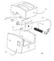
- FIGS. 2A-2Dillustrate an exemplary embodiment (Embodiment II) of a tapered sliding base ZP-EIS device with incorporated BDFT screws in closed ( FIG. 2A ), semi-expanded ( FIG. 2B ), and fully expanded ( FIG. 2C ) positions, and in an exploded view ( FIG. 2D ).
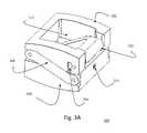
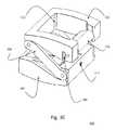
- FIGS. 3A-3Dillustrate an exemplary embodiment (Embodiment III) of a scissors jack driven ZP-EIS device without incorporated BDFT screws in closed ( FIG. 3A ), semi-expanded ( FIG. 3B ), and fully expanded ( FIG. 3C ) positions, and in exploded view ( FIG. 3D ).
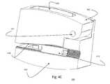
- FIGS. 4A-4Cillustrate an exemplary embodiment (Embodiment IV) of a tapered thread driven ZP-EIS device without incorporated BDFT screws in closed ( FIG. 4A ), semi-expanded/fully expanded positions ( FIG. 4B ), and in cross-sectional view ( FIG. 4C ).
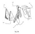
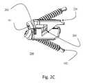
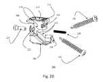
- FIGS. 5A-5Dillustrate an exemplary embodiment (Embodiment V) of a dry anchor driven ZP-EIS device without incorporated BDFT screws in closed ( FIG. 5A ), semi-expanded ( FIG. 5B ), and fully expanded ( FIG. 5C ) positions, and in an exploded view ( FIG. 5D ).
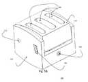
- FIGS. 6A-6Dillustrate an exemplary embodiment (Embodiment VI) of a modified wedge driven ZP-EIS device without incorporated BDFT screws in closed ( FIG. 6A ), semi-expanded ( FIG. 6B ), and fully expanded ( FIG. 6C ) positions, and in an exploded view ( FIG. 6D ).
- FIGS. 7A-7Dillustrate an exemplary embodiment (Embodiment VII) of a worm drive ZP-EIS device without incorporated BDFT screws in closed ( FIG. 7A ), semi-expanded ( FIG. 7B ), and fully expanded ( FIG. 7C ) positions, and in an exploded view ( FIG. 7D ).
- FIGS. 7E (i) and 7 E(ii)illustrate top, perspective views of an intervertebral cage construct according to an exemplary embodiment of the invention.
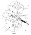
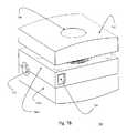
- FIG. 8A-8Cillustrate a positioning tool/screw guide/box expander in oblique perspective ( FIG. 8A ), lateral ( FIG. 8B ), and exploded ( FIG. 8C ) views according to an exemplary embodiment, which is shown coupled to the exemplary non-tapered sliding base ZP-EIS device illustrated in FIGS. 1A-1B .
- FIGS. 8D (i) and 8 D(ii)illustrate superior oblique perspective views of the positioning tool/drill guide/box expander component, according to an exemplary embodiment, which may be optionally used for the exemplary embodiments illustrated in FIGS. 1A-1B and 2A-2D .
- FIGS. 8E-8Gillustrate sequential steps Step I ( FIG. 8E ), step II ( FIG. 8F ), and step III ( FIG. 8G )) of the positioning tool/screw guide/box expander assembly according to an exemplary embodiment.
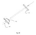
- FIGS. 8H-8Iillustrate three-dimensional views of positioning tools, according to exemplary embodiments, for impaction and placement of two transvertebral screws, for example, of the exemplary embodiments illustrated in FIGS. 1A-1B and 2A-2D .
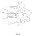
- FIGS. 8J-8Killustrate the insertion of expandable Lumbar bi-directional screw box with two BDFT screws into the Lumbar spine in oblique ( FIG. 8J ) and lateral ( FIG. 8K ) views.
- FIGS. 1A-8Killustrate exemplary embodiments of ZP-EIS devices that can solve the above described problems and others in the spine by insertion of the ZP-EIS devices into the denuded intervertebral disc space according to the features illustrated in the exemplary embodiments (I-VII).
- FIGS. 1A-1Billustrate three-dimensional views of a ZP-EIS device 100 according to embodiment I, with two BDFT screws 101 , 102 .
- the expandable ZP-EIS device 100includes of top and bottom triangular sliding bases 103 , 104 ( FIGS. 1A-1B ).
- the superior and inferior segments of the height/depth adjusting screw 105are integrated and connected to the two separate top and bottom triangular bases 103 , 104 , respectively.
- this adjusting (rotation) screw 105By turning this adjusting (rotation) screw 105 back and forth, i.e. clock-wise, and counter clockwise, the sliding rails 106 of the top triangular base 103 ( FIGS. 1A-1B ) slide up and down the rail inserts 107 on the bottom triangular base 104 ( FIGS. 1A-1B ).
- This actionwill simultaneously alter the intervertebral height and depth of the device 100 allowing individualized custom fitting of the ZPEIS device 100 conforming to the dimensions of the disc space.
- a transvertebral screw 101penetrates the top base 103 , and a transvertebral screw 102 traverses the bottom base 104 of the screw box (device 100 ).
- the two screws 101 , 102traverse the screw box 100 in opposing directions, bi-directionally.
- the external edges of the triangular bases 103 , 104 in contact with vertebral body surfacescan include ridges 107 , which facilitates the ZP-EIS device 100 incorporation into and fusion with the superior and inferior vertebral bodies ( FIGS. 1A-1B ).
- Both top and bottom ZP-EIS bases 103 , 104can be perforated with holes 108 to allow bone placement for fusion.
- the entire constructfurthermore, can be hollow to allow filling with bone filling material.
- the exemplary devicefunctions as both an intervertebral bone fusion spacer and bi-directional transvertebral screw fusion device.
- FIGS. 2A-2Dillustrate a ZP-EIS device 200 according to exemplary embodiment II.
- This exemplary device 200incorporates BDFT screws and employs a fusion wedge mechanism of expansion.
- the device 200includes a contoured top 208 and bottom 206 housing which have tapered edges and are coupled to each other by a diagonal dovetail interface 204 which constrains the components 208 , 206 to translate linearly relative to each other.
- the linear translationcauses a vertical separation of the top 208 and bottom 206 housing surfaces which are parallel to each other.
- the positionis secured and adjusted by a threaded rotation screw 220 coupled to a nut 224 and a retaining ring 222 and passed through the top 208 and bottom 206 housing pieces. As the threaded rotation screw 220 is rotated further into the nut 224 , the housing pieces 208 , 206 expand vertically.
- this adjusting (rotation) screw 220By turning this adjusting (rotation) screw 220 back and forth i.e. clock-wise, and counter clockwise, the sliding rails 210 of the top housing piece 208 slide up and down the rail inserts 212 on the bottom housing piece 206 .
- This actionwill simultaneously alter the intervertebral height and depth of the device 200 allowing individualized custom fitting of the ZP-EIS conforming to the dimensions of the disc space.
- a transvertebral screw 101penetrates the top housing piece 208
- a transvertebral screw 102traverses the bottom housing piece 206 of the device 200 .
- the two screws 101 , 102traverse the device 200 in opposing directions, bi-directionally.
- the external edges of the housing pieces in contact with vertebral body surfacesinclude ridges 216 .
- Both top and bottom ZP-EIS housing bases 208 , 206are perforated with holes 214 to allow bone placement for fusion.
- the entire device 200furthermore, can be hollow to allow bone filling.
- the exemplary device 200functions as both an intervertebral bone fusion spacer and bi-directional transvertebral screw fusion device.
- the device 200can include a tapered edge 226 (shown for example in FIGS. 2A-2B ), which allows easier introduction and insertion of the device 200 into the disc space.
- FIGS. 3A-3Dillustrate a ZP-EIS device 300 according to exemplary embodiment III, which employs a scissor jack expansion mechanism.
- top 302 and bottom 304 housingare attached by one internal linkage arm 310 , and two external linkage arms 308 .
- the device 300can include indentations 306 on each lateral side close to the top of the device 300 to mate with the prongs of the universal tool (for example, as described in FIGS. 8A-8I ) to assist in grasping, inserting and impacting the device 300 .
- a lead screw or rotation screw 314is mounted in the bottom housing 304 and secured in place with a retaining ring 316 . When the lead (rotation) screw 314 is rotated by an external tool (for example, as described in FIGS.
- the screw 314causes the linear displacement of the separation block 318 which is hinged to the internal linkage 310 .
- the horizontal motion of the separation blockcauses the top 302 and bottom 304 housing pieces to separate vertically.
- the separation distancedepends on the amount of rotation of the lead (rotation) screw 314 , and is limited by the freedom of the separation block 318 to move within the bottom housing 304 .
- the exemplary embodimentcan include a plurality of pins, such as eight pins 320 , 322 , 324 , to secure the external linkage arms 308 to the top 302 and bottom 304 housing units and to the separation block 318 .
- the top housing 302 and bottom housing 304can include one or more cavities 312 for bone incorporation/fusion.
- FIGS. 4A-4Cillustrate a ZP-EIS device 400 according to exemplary embodiment IV, which employs a tapered thread mechanism of expansion.
- the exemplary device 400can include a top housing 402 and bottom housing 404 , which can be attached by one or more pins, such as two pins 412 , which allow rotation of the top housing 402 and bottom housing 404 relative to each other about the axis of the pins 412 .
- the top housing 402 and/o bottom housing 404can include indentations 406 on their lateral sides close to the top of the device 400 to mate with the prongs of a tool or universal tool (e.g., prongs 806 in FIGS. 8A-8I ) to assist in grasping, inserting and impacting the device 400 .
- the bottom housing 404can include a mount for the rotation screw 410 ( FIG.
- the device 400can include a sloped ridge 414 , as exemplary illustrated in FIG. 4C .
- the device 400can include one or more bone cavities in the top housing 402 and bottom housing 404 for bone fusion.
- FIGS. 5A-5Dillustrate exemplary embodiments of a ZP-EIS device according to embodiment V, which employs an anchor mechanism of expansion.
- the top housing 502 and bottom housing 504can be coupled or attached by one or more pins, such as two pins 512 , which allow rotation of the top housing 502 and bottom housing 504 relative to each other about the axis of the pins 512 .
- the top housing 502 and/or the bottom housing 504can include indentations 506 on their lateral sides close to the top of the device 500 to mate with the prongs of a tool or universal tool (e.g. see FIGS. 8A-8I ) to assist in grasping, inserting and impacting the device 500 .
- the bottom housing 504can include, for example, a mount for the lead (rotation) screw 510 , which can control the relative angular orientation of the two housing pieces 502 , 504 .
- the lead (rotation) screw 510can be secured with one or more retaining rings, such as two retaining rings 518 .
- an external toole.g., such as the tool shown in FIGS. 8A-8I
- the screw 510causes lateral motion of a translation nut 516 , which is attached to two linkage bars 514 to a second nut 516 fixed to the bottom housing.
- a plurality of pinssuch as six pins 512 , can secure the linkage bars or arms 514 to each other and to translation nuts 516 .
- the linkage bars or arms 514extend outside of the bottom housing 504 , pushing against the top housing 502 .
- the linkage bars or arms 514can be replaced by a solid material such as spring steel which can bend to produce the same effect.
- the device 500can include one or more bone cavities that can be incorporated into the top housing 502 and the bottom housing 504 for bone fusion.
- FIGS. 6A-6Dillustrate exemplary embodiments of a ZP-EIS device 600 according to embodiment VI which employs a modified wedge expansion mechanism.
- the device 600includes a top housing 602 and a bottom housing 604 that can be attached or coupled by one or more pins, such as two pins 612 , which allow rotation of the top housing 602 and the bottom housing 604 relative to each other about the axis of the pins 612 .
- the top housing 602 and/or the bottom housing 604can include indentations 606 on their lateral sides close to the top of the device 600 to mate with the prongs of a tool, such as prongs 806 of the universal tool shown in FIGS. 8A-8I , to assist in grasping, inserting and impacting the device 600 .
- the bottom housing 604can include a mount for the lead (rotation) screw 610 , which can control the relative angular orientation of the two housing pieces 602 , 604 .
- the lead (rotation) screw 610can be secured with one or more retaining rings, such as two retaining rings 618 .
- the screw 610When the screw 610 is rotated by an external tool (e.g., the tool shown in FIGS. 8A-8I ), the screw 610 causes lateral motion of a wedge-shaped translation nut 616 .
- the nut 616engages an inner tapered surface of the top housing 602 and forces the top housing piece 602 to rotate away from the bottom housing 604 .
- the device 600can include one or more bone cavities 608 incorporated into the top housing 602 and/or bottom housing 604 for bone fusion.
- FIGS. 7A-7Dillustrate exemplary embodiments of a ZP-EIS device 700 according to embodiment VII, which employs a worm drive (gear) mechanism.
- the device 700includes a worm drive design that allows a user to rotate a worm gear/drive 712 with an external tool ( FIG. 8 ) to control the translation of the top housing 702 relative to the bottom housing 704 a , 704 b .
- the worm gear drive 712engages a spur gear mount 714 which has internal threading for engaging a corresponding part, such as a threaded stud of bolt 720 , to couple the spur gear mount 714 to the top housing 702 .
- the top housing 702can include a plurality of pins, such as four pins 712 , which extend into the bottom housing 704 a , 704 b .
- the bottom housing 704can include two halves 704 a , 704 b to secure the worm drive 710 and spur mount 714 in place.
- a worm retaining ring and a spur retaining ring 716also can be used to secure the worm gear drive 710 and the spur gear mount 714 .
- the device 700can include one or more bone cavities 708 that are incorporated into the top housing 702 and/or bottom housing 704 a , 704 b for bone fusion.
- the top housing 702 and/or bottom housing 704 a , 704 bcan include one or more indentations 706 on its lateral sides close to the top of the device 700 to mate with prongs of a tool, such as prongs 806 of the universal tool 800 in FIGS. 8A-8I , to assist in grasping, inserting and impacting the device 700 .
- a toolsuch as prongs 806 of the universal tool 800 in FIGS. 8A-8I
- FIGS. 8A-8Cillustrate three-dimensional views of exemplary embodiments of the external drill/screw guide-box expander universal tool 800 which can be used to assist in both screw trajectory and box expansion of an expandible device, such as the exemplary embodiments of devices illustrated in embodiments I and II, and for device expansion of the devices illustrated in embodiments III-VII.
- the same universal tool 800can be utilized for all the exemplary embodiments illustrated in embodiments I-VII.
- the external drill/screw guide 850may not be needed or used for embodiments II-VII.
- the prongs 806can be inserted into the indentations (e.g., 202 , 306 , 406 , 506 , 606 , 706 ) of the sides of the devices (e.g., 100 , 200 , 300 , 400 , 500 , 600 , 700 ) according to one or all of the exemplary embodiments illustrated in embodiments I-VII, and implant the device into the intervertebral space.
- an Allen keye.g., as shown in FIG.
- the device 8can be used to expand the device (e.g., 100 , 200 , 300 , 400 , 500 , 600 , 700 ) by turning the adjustment (rotation) screw (e.g., 105 , 220 , 314 , 410 , 510 , 610 , 710 ).
- the adjustment (rotation) screwe.g., 105 , 220 , 314 , 410 , 510 , 610 , 710 .
- the exemplary toolcan include, among other things, an Allen key 801 , a spring 802 , a handle 803 , a griper 804 and a screw guide 805 .
- the Allen key 801when inserted in the insertion 814 and turned, can turn the rotation screws (e.g., 105 , 220 , 314 , 410 , 510 , 610 , 710 ) of one or all of the exemplary embodiments I-VII.
- the griper 804includes griper prongs 806 , which insert into grooves 509 of the screw guide 805 and the screw box indentations (e.g., 202 ) in the exemplary embodiment illustrated in embodiment I (as shown in FIGS.
- each longitudinal end of the screw box 100can include a slot or indentation 108 formed adjacent to an edge of an upper surface of the screw box 100 for engaging a protuberant extension of a tool, such as the protuberant extension 807 of the tool 800 .
- FIG. 8Dillustrates a superior oblique view of the screw guide 805 demonstrating insertions 809 for griper prong 086 , built-in trajectory guides 811 , 812 for insertion of screws 101 and 102 , and the Allen key 801 .
- This exemplary embodimentcan be limited, for example, to use with the devices of embodiments I and II, which includes BDFT screws.
- FIGS. 8E-8Gillustrate three-dimensional views of the sequential steps necessary for the external guide assembly.
- FIG. 8Eillustrates the insertion of the Allen key 801 into the handle 803 .
- FIG. 5Fillustrates the insertion of the handle 803 through the spring 802 and griper 804 .
- FIG. 8Gillustrates insertion of the griper 804 into the screw guide 805 .
- the griper prongs 806can include medially oriented male protuberant extensions 807 that engage the slot or indentation of a device, such as indentation 108 of device 100 , thereby perfectly aligning the prongs 805 of the tool 800 with the device (e.g., 100 , 200 , 300 , 400 , 500 , 600 , 700 ).
- This exemplary embodimentcan be limited, for example, to use with the devices of embodiments I and II.
- FIG. 8Hillustrates a three-dimensional view of another exemplary embodiment of a positioning tool 800 for impaction and placement of two transvertebral screws 201 , 202 for example, for use with the exemplary embodiments I and II.
- the screw guide 805can include insertions 809 for receiving the griper prong 806 , built-in trajectory guides 811 , 812 for insertion of screws 101 and 102 , and the Allen key 801 .
- the driver assembly 850can include a screw driver 851 , a flexible shaft 852 and a square recess bit 853 .
- This exemplary devicecan facilitate turning the screws 101 , 102 into the bone.
- the flexible shaft 852can facilitate the avoidance of spinous processes which might hinder the screw driving if the shaft 852 were straight.
- the positioning tool 800can have a rectangular handle, as shown for example in Embodiment I, or a circular handle, as exemplary shown in Embodiment II. This exemplary embodiment can serve to position a screw box within the intervertebral space, and screws 101 , 102 within the screw box or device.
- the screw box or devicee.g., 100 , 200 , 300 , 400 , 500 , 600 , 700
- the screw box or devicecan be impacted by tapping the handle 803 with a mallet (not shown).
- the griper handle 803inserts into the screw guide and the screw box or device (e.g., 100 , 200 , 300 , 400 , 500 , 600 , 700 ), which maintains alignment.
- An exemplary embodiment of a ZP-EIS deviceas illustrated in embodiments (I-VII), can be inserted into the intervertebral space (for example as shown in FIGS. 8J and 8K ) after an adequate discectomy is performed in any disc space throughout the entire spine upon their exposure anteriorly, anterio-laterally, laterally, far laterally or posteriorly.
- I-II of the ZP-EIS devicescan be inserted into the disc space by a tool or universal tool, such as the universal tool 800 in FIGS. 8A-8I .
- the grab prongs of tool 800can attach to the insets or indentations (e.g., 202 , 306 , 406 , 506 , 606 , 706 ) on the side of the devices.
- the rotation screw(e.g., 105 , 220 , 314 , 410 , 510 , 610 , 710 ) of each embodiment is turned by rotating the Allen key 801 of the tool 800 to expand the device (e.g., 100 , 200 , 300 , 400 , 500 , 600 , 700 ) to the desirable disc height achieving the desirable intervertebral distraction deemed necessary for the individual patient and disc space.
- BDFT screws 101 , 102are inserted and screwed into the vertebral body above and below securing the device (e.g., 100 , 200 , 300 , 400 , 500 , 600 , 700 ) to the vertebral bodies with screws 101 , 102 .
- the bone cavities of each devicePrior to implantation of the device (e.g., 100 , 200 , 300 , 400 , 500 , 600 , 700 ), the bone cavities of each device can be filled with any type of bone fusion material.
- the ZP-EIS device(e.g., 100 , 200 , 300 , 400 , 500 , 600 , 700 ) can be inserted into the disc space by the same universal tool, such as tool 800 .
- the grabs prongs 806 of the tool 800attach to the insets or indentations (e.g., 202 , 306 , 406 , 506 , 606 , 706 ) on the side of the devices (e.g., 100 , 200 , 300 , 400 , 500 , 600 , 700 ) on the side of the devices (e.g., 100 , 200 , 300 , 400 , 500 , 600 , 700 ).
- the rotation screw(e.g., 105 , 220 , 314 , 410 , 510 , 610 , 710 ) is turned by rotating the Allen key 801 of the tool 800 expanding the device (e.g., 100 , 200 , 300 , 400 , 500 , 600 , 700 ) to the desirable disc height achieving the desirable intervertebral distraction deemed necessary for the individual patient and disc space.
- the bone cavities of each devicee.g., 100 , 200 , 300 , 400 , 500 , 600 , 700
- the exemplary embodiments of the present inventionmay provide effective and safe techniques that overcome the problems associated with current transpedicular and/or plated fusion technology employed for many degenerative stable and unstable spine diseases. These exemplary embodiments may replace much pedicle screw-based and plated based instrumentation in many but not all degenerative spine conditions.
- the exemplary embodiments of zero-profile devicescan provide markedly significantly decreased risk of misguided screw placement, and hence decreased risk of neural and vascular injury, and blood loss.
- the exemplary embodimentscan provide decreased recovery and back to work time.
- the exemplary embodiments of devicesmay lead to similar if not equal fusion with significantly less morbidity, and hence overall make the exemplary devices a major advance in the evolution of spinal instrumented technology leading to advances in the care of the spinal patient.
- an intervertebral fusion deviceuses a threaded rod mechanism located at the peripheral of the box to control expansion of the device.
- the devicecan include a cavity within the walls for placement of bone material for fusion.
- an intervertebral fusion devicecan include a threaded rod which can obstruct (inhibit) expansion of the device when it is not being turned.
- the threaded rodcan be disposed at the front anterior part of the box or device.
- an intervertebral fusion devicecan include a threaded rod, which exerts a clamping force to expand the device until the device properly accommodates the dimensions of the intervertebral disc space and distracts the space based on individual anatomy and surgical judgment.
- the devicecan include a cavity for bone in-between the walls of the box.
- an expandable intervertebral fusion devicecan includes indentations on its sides to accommodate a placement tool.
- an expandable intervertebral fusion devicecan be adjusted by using a threaded rod as a wedge to pivot components within the device.
- the threaded rodcan be accessible from the front anterior of the box or device.
- an expandable fusion devicecan include a threaded rod to expand a spacer.
- the threaded rodcan be used as a wedge to mechanically separate the pieces.
- the threaded rodcan be accessible from the front anterior of the box or device.
- an expandable fusion devicecan include wedge components which translate relative to each other along a contact.
- the degree of expansioncan be determined by an adjustment rod located at the peripheral of the box or device.
- an expandable fusion devicein another embodiment, includes components which are mechanically linked together. The expansion of the device is controlled by the user via an adjustment rod coupled to a mechanical transmission that causes mechanical components within the device to separate. The threaded rod is accessible from the front anterior of the box or device.
- an expandable fusion devicecan be provide wherein the position of the device is secured and adjusted by a threaded rod that is mechanically linked to housing pieces. When the threaded rod is rotated, the threaded rod forces the pieces to separate.
- an intervertebral fusion deviceis provide wherein the two internal screw guides are in the top housing unit.
- an intervertebral fusion expansile devicewherein the center of the two internal screw guides could be in quadrants I and III or II and IV.
- an expandable fusion devicecan be provided that uses a threaded rod (rotation screw) to expand the device using a metal driver as the wedge to mechanically separate the pieces.
- a threaded rodrotation screw
- an expandable fusion devicecan be adjusted by using a threaded rod (rotation screw) as a wedge to offset the opposing cages.
- an expandable intervertebral fusion devicein another embodiment, can be provided wherein its position is secured and adjusted by a threaded rod (rotation screw) coupled to a nut and passed through the top and bottom housing pieces. As the threaded rod is rotated further into the nut, the pieces separate.
- a threaded rodrotation screw
- an expandable intervertebral fusion devicecan include a tapered edge to allow contoured insertion into the disc space.
- an intervertebral fusion devicecan be provided wherein the internal screw guides for screw insertion within the device are diagonal to each other within the xyz plane.
- an intervertebral fusion devicewherein the internal screw guides can be adjacent and somewhat diagonal to each other within the xyz plane.
- an intervertebral fusion devicecan be provided wherein the majority each of the 2 screw holes can be in quadrant I and III or II and IV within the xyz plane.
- an intervertebral fusion devicecan be provided wherein the screw guides can have approximately the same xy coordinates and have different z coordinates or vice versa.
- an intervertebral fusion devicecan be provided wherein the center of the two internal screw guides could be in quadrants I and III or II and IV within the xyz plane.
- an intervertebral fusion devicecan be provided wherein one screw guide is in the top housing unit, and another screw guide is in the bottom housing unit.
- an intervertebral fusion deviceuses a threaded rod (rotation screw) to engage a moveable component which engages a linkage to expand the device.
- an intervertebral fusion deviceuses a threaded rod (rotation screw) to engage a wedge which engages its attaching linkages to expand the device.
- an expandable fusion devicecan be provided that can be adjusted using a threaded rod (rotation screw) coupled to a scissor-jack linkage.
- an expandable fusion devicecan be held together with fastener(s). These fasteners constrain the box to one degree of freedom.
- Part of the mechanismcontains a mount for the rotation screw, which can control the movement of the pieces. As the screw is turned, it engages the teeth of the mechanism and acts as a wedge to rotate the pieces away from each other.
- an expandable fusion device adjusted by using a threaded rodcan be used as a wedge to offset the opposing cage surfaces.
- an expandable fusion devicecan be provided that uses a threaded rod (rotation screw) to expand the device using a metal driver as the wedge to mechanically separate the pieces.
- a threaded rodrotation screw
- an expandable fusion devicecan be provided that can be adjusted by a threaded rod (rotation screw) coupled to a nut which translates to deform an elastomeric material used to force the expansion of the device.
- a threaded rodrotation screw
- an expandable fusion devicein another embodiment, has a threaded rod (rotation screw) that engages a wedge to control the expansion of the device.
- an expandable fusion devicecan be provided that can be contained by fasteners and retaining rings.
- an expandable fusion devicecan be provided that can be adjusted by a threaded rod (rotation screw) coupled to a wedge that can move the opposing cage surfaces.
- an expandable fusion deviceuses a worm drive to turn a gear that acts as a wedge to expand the device.
- an expandable fusion devicein another embodiment, includes fasteners and retaining rings containing and constraining the device pieces.
- an expandable fusion devicecan be provided that can be adjusted by a worm gear coupled to an internally threaded spur gear which, upon rotation, linearly advances a threaded component.
- a toolin another embodiment, includes a handle, a gripper cooperating with the handle and having a plurality of prongs, a screw guide held in place the plurality of prongs, for controlling the direction of self-drilling screws that are screwed into the vertebral bodies, and an Allen key which expands expandable intervertebral devices.
Landscapes
- Health & Medical Sciences (AREA)
- Orthopedic Medicine & Surgery (AREA)
- Biomedical Technology (AREA)
- Engineering & Computer Science (AREA)
- Life Sciences & Earth Sciences (AREA)
- Neurology (AREA)
- General Health & Medical Sciences (AREA)
- Heart & Thoracic Surgery (AREA)
- Veterinary Medicine (AREA)
- Public Health (AREA)
- Animal Behavior & Ethology (AREA)
- Surgery (AREA)
- Transplantation (AREA)
- Cardiology (AREA)
- Oral & Maxillofacial Surgery (AREA)
- Vascular Medicine (AREA)
- Molecular Biology (AREA)
- Medical Informatics (AREA)
- Nuclear Medicine, Radiotherapy & Molecular Imaging (AREA)
- Rheumatology (AREA)
- Physical Education & Sports Medicine (AREA)
- Prostheses (AREA)
- Surgical Instruments (AREA)
Abstract
Description
Claims (20)
Priority Applications (5)
| Application Number | Priority Date | Filing Date | Title |
|---|---|---|---|
| US15/820,232US10016284B2 (en) | 2005-04-12 | 2017-11-21 | Zero-profile expandable intervertebral spacer devices for distraction and spinal fusion and a universal tool for their placement and expansion |
| US16/025,667US10426633B2 (en) | 2005-04-12 | 2018-07-02 | Zero-profile expandable intervertebral spacer devices for distraction and spinal fusion and a universal tool for their placement and expansion |
| US16/587,993US11096797B2 (en) | 2005-04-12 | 2019-09-30 | Zero-profile expandable intervertebral spacer devices for distraction and spinal fusion and a universal tool for their placement and expansion |
| US17/408,068US12011367B2 (en) | 2005-04-12 | 2021-08-20 | Expandable intervertebral device |
| US18/663,585US20240366399A1 (en) | 2012-10-25 | 2024-05-14 | Zero-profile expandable intervertebral spacer devices for distraction and spinal fusion and a universal tool for their placement and expansion |
Applications Claiming Priority (15)
| Application Number | Priority Date | Filing Date | Title |
|---|---|---|---|
| US67023105P | 2005-04-12 | 2005-04-12 | |
| US11/208,644US7704279B2 (en) | 2005-04-12 | 2005-08-23 | Bi-directional fixating transvertebral body screws, zero-profile horizontal intervertebral miniplates, expansile intervertebral body fusion devices, and posterior motion-calibrating interarticulating joint stapling device for spinal fusion |
| US11/536,815US7846188B2 (en) | 2005-04-12 | 2006-09-29 | Bi-directional fixating transvertebral body screws, zero-profile horizontal intervertebral miniplates, total intervertebral body fusion devices, and posterior motion-calibrating interarticulating joint stapling device for spinal fusion |
| US11/842,855US7942903B2 (en) | 2005-04-12 | 2007-08-21 | Bi-directional fixating transvertebral body screws and posterior cervical and lumbar interarticulating joint calibrated stapling devices for spinal fusion |
| US13/084,543US8353913B2 (en) | 2005-04-12 | 2011-04-11 | Bi-directional fixating transvertebral body screws and posterior cervical and lumbar interarticulating joint calibrated stapling devices for spinal fusion |
| US13/108,982US9005293B2 (en) | 2005-04-12 | 2011-05-16 | Bi-directional fixating transvertebral body screws and posterior cervical and lumbar interarticulating joint calibrated stapling devices for spinal fusion |
| US13/210,157US9889022B2 (en) | 2005-04-12 | 2011-08-15 | Bi-directional fixating transvertebral body screws and posterior cervical and lumbar interarticulating joint calibrated stapling devices for spinal fusion |
| US13/210,162US9895238B2 (en) | 2005-04-12 | 2011-08-15 | Bi-directional fixating transvertebral body screws and posterior cervical and lumbar interarticulating joint calibrated stapling devices for spinal fusion |
| US13/210,150US9867719B2 (en) | 2005-04-12 | 2011-08-15 | Bi-directional fixating transvertebral body screws and posterior cervical and lumbar interarticulating joint calibrated stapling devices for spinal fusion |
| US13/210,168US9907674B2 (en) | 2005-04-12 | 2011-08-15 | Bi-directional fixating transvertebral body screws and posterior cervical and lumbar interarticulating joint calibrated stapling devices for spinal fusion |
| US201261718707P | 2012-10-25 | 2012-10-25 | |
| US13/741,361US9301854B2 (en) | 2005-04-12 | 2013-01-14 | Bi-directional fixating transvertebral body screws and posterior cervical and lumbar interarticulating joint calibrated stapling devices for spinal fusion |
| US201361801783P | 2013-03-15 | 2013-03-15 | |
| US14/063,197US9848993B2 (en) | 2005-04-12 | 2013-10-25 | Zero-profile expandable intervertebral spacer devices for distraction and spinal fusion and a universal tool for their placement and expansion |
| US15/820,232US10016284B2 (en) | 2005-04-12 | 2017-11-21 | Zero-profile expandable intervertebral spacer devices for distraction and spinal fusion and a universal tool for their placement and expansion |
Related Parent Applications (1)
| Application Number | Title | Priority Date | Filing Date |
|---|---|---|---|
| US14/063,197ContinuationUS9848993B2 (en) | 2005-04-12 | 2013-10-25 | Zero-profile expandable intervertebral spacer devices for distraction and spinal fusion and a universal tool for their placement and expansion |
Related Child Applications (1)
| Application Number | Title | Priority Date | Filing Date |
|---|---|---|---|
| US16/025,667ContinuationUS10426633B2 (en) | 2005-04-12 | 2018-07-02 | Zero-profile expandable intervertebral spacer devices for distraction and spinal fusion and a universal tool for their placement and expansion |
Publications (2)
| Publication Number | Publication Date |
|---|---|
| US20180078383A1 US20180078383A1 (en) | 2018-03-22 |
| US10016284B2true US10016284B2 (en) | 2018-07-10 |
Family
ID=51421344
Family Applications (5)
| Application Number | Title | Priority Date | Filing Date |
|---|---|---|---|
| US14/063,197Expired - LifetimeUS9848993B2 (en) | 2005-04-12 | 2013-10-25 | Zero-profile expandable intervertebral spacer devices for distraction and spinal fusion and a universal tool for their placement and expansion |
| US15/820,232Expired - LifetimeUS10016284B2 (en) | 2005-04-12 | 2017-11-21 | Zero-profile expandable intervertebral spacer devices for distraction and spinal fusion and a universal tool for their placement and expansion |
| US16/025,667Expired - LifetimeUS10426633B2 (en) | 2005-04-12 | 2018-07-02 | Zero-profile expandable intervertebral spacer devices for distraction and spinal fusion and a universal tool for their placement and expansion |
| US16/587,993Active2025-12-26US11096797B2 (en) | 2005-04-12 | 2019-09-30 | Zero-profile expandable intervertebral spacer devices for distraction and spinal fusion and a universal tool for their placement and expansion |
| US17/408,068Active2026-03-15US12011367B2 (en) | 2005-04-12 | 2021-08-20 | Expandable intervertebral device |
Family Applications Before (1)
| Application Number | Title | Priority Date | Filing Date |
|---|---|---|---|
| US14/063,197Expired - LifetimeUS9848993B2 (en) | 2005-04-12 | 2013-10-25 | Zero-profile expandable intervertebral spacer devices for distraction and spinal fusion and a universal tool for their placement and expansion |
Family Applications After (3)
| Application Number | Title | Priority Date | Filing Date |
|---|---|---|---|
| US16/025,667Expired - LifetimeUS10426633B2 (en) | 2005-04-12 | 2018-07-02 | Zero-profile expandable intervertebral spacer devices for distraction and spinal fusion and a universal tool for their placement and expansion |
| US16/587,993Active2025-12-26US11096797B2 (en) | 2005-04-12 | 2019-09-30 | Zero-profile expandable intervertebral spacer devices for distraction and spinal fusion and a universal tool for their placement and expansion |
| US17/408,068Active2026-03-15US12011367B2 (en) | 2005-04-12 | 2021-08-20 | Expandable intervertebral device |
Country Status (1)
| Country | Link |
|---|---|
| US (5) | US9848993B2 (en) |
Cited By (24)
| Publication number | Priority date | Publication date | Assignee | Title |
|---|---|---|---|---|
| US20210068959A1 (en)* | 2019-09-11 | 2021-03-11 | Gary R. McLuen | Bone fusion device, system and method |
| US11096797B2 (en) | 2005-04-12 | 2021-08-24 | Moskowitz Family Llc | Zero-profile expandable intervertebral spacer devices for distraction and spinal fusion and a universal tool for their placement and expansion |
| US11285014B1 (en) | 2020-11-05 | 2022-03-29 | Warsaw Orthopedic, Inc. | Expandable inter-body device, system, and method |
| US11291554B1 (en) | 2021-05-03 | 2022-04-05 | Medtronic, Inc. | Unibody dual expanding interbody implant |
| US11376134B1 (en) | 2020-11-05 | 2022-07-05 | Warsaw Orthopedic, Inc. | Dual expanding spinal implant, system, and method of use |
| US11395743B1 (en) | 2021-05-04 | 2022-07-26 | Warsaw Orthopedic, Inc. | Externally driven expandable interbody and related methods |
| US11517443B2 (en) | 2020-11-05 | 2022-12-06 | Warsaw Orthopedic, Inc. | Dual wedge expandable implant, system and method of use |
| US11564724B2 (en) | 2020-11-05 | 2023-01-31 | Warsaw Orthopedic, Inc. | Expandable inter-body device, system and method |
| US11612499B2 (en) | 2021-06-24 | 2023-03-28 | Warsaw Orthopedic, Inc. | Expandable interbody implant |
| US11638653B2 (en) | 2020-11-05 | 2023-05-02 | Warsaw Orthopedic, Inc. | Surgery instruments with a movable handle |
| US11730608B2 (en) | 2021-07-13 | 2023-08-22 | Warsaw Orthopedic, Inc. | Monoblock expandable interbody implant |
| US11806250B2 (en) | 2018-02-22 | 2023-11-07 | Warsaw Orthopedic, Inc. | Expandable spinal implant system and method of using same |
| US11833059B2 (en) | 2020-11-05 | 2023-12-05 | Warsaw Orthopedic, Inc. | Expandable inter-body device, expandable plate system, and associated methods |
| US11850163B2 (en) | 2022-02-01 | 2023-12-26 | Warsaw Orthopedic, Inc. | Interbody implant with adjusting shims |
| US11963881B2 (en) | 2020-11-05 | 2024-04-23 | Warsaw Orthopedic, Inc. | Expandable inter-body device, system, and method |
| US12121453B2 (en) | 2020-11-05 | 2024-10-22 | Warsaw Orthopedic, Inc. | Dual wedge expandable implant with eyelets, system, and method of use |
| US20240366399A1 (en)* | 2012-10-25 | 2024-11-07 | Moskowitz Family Llc | Zero-profile expandable intervertebral spacer devices for distraction and spinal fusion and a universal tool for their placement and expansion |
| US12171439B2 (en) | 2020-11-05 | 2024-12-24 | Warsaw Orthopedic, Inc. | Protected drill |
| US12239544B2 (en) | 2020-11-05 | 2025-03-04 | Warsaw Orthopedic, Inc. | Rhomboid shaped implants |
| US12268614B2 (en) | 2021-06-24 | 2025-04-08 | Warsaw Orthopedic, Inc. | Interbody implant with adjusting shims |
| US12295865B2 (en) | 2021-06-24 | 2025-05-13 | Warsaw Orthopedic, Inc. | Expandable interbody implant and corresponding inserter |
| US12318308B2 (en) | 2020-11-05 | 2025-06-03 | Warsaw Orthopedic, Inc. | Dual expandable inter-body device |
| US12414863B2 (en) | 2021-06-24 | 2025-09-16 | Warsaw Orthopedic, Inc. | Expandable interbody implant and corresponding surgical tool |
| US12440349B2 (en) | 2022-02-04 | 2025-10-14 | Warsaw Orthopedic, Inc. | Expandable interbody implant and breakoff screw |
Families Citing this family (136)
| Publication number | Priority date | Publication date | Assignee | Title |
|---|---|---|---|---|
| US7041309B2 (en) | 2002-06-13 | 2006-05-09 | Neuropro Technologies, Inc. | Spinal fusion using an HMG-CoA reductase inhibitor |
| US6793678B2 (en) | 2002-06-27 | 2004-09-21 | Depuy Acromed, Inc. | Prosthetic intervertebral motion disc having dampening |
| AU2004212942A1 (en) | 2003-02-14 | 2004-09-02 | Depuy Spine, Inc. | In-situ formed intervertebral fusion device |
| US20040267367A1 (en) | 2003-06-30 | 2004-12-30 | Depuy Acromed, Inc | Intervertebral implant with conformable endplate |
| US8636802B2 (en) | 2004-03-06 | 2014-01-28 | DePuy Synthes Products, LLC | Dynamized interspinal implant |
| US7955357B2 (en) | 2004-07-02 | 2011-06-07 | Ellipse Technologies, Inc. | Expandable rod system to treat scoliosis and method of using the same |
| US8597360B2 (en) | 2004-11-03 | 2013-12-03 | Neuropro Technologies, Inc. | Bone fusion device |
| US7846188B2 (en) | 2005-04-12 | 2010-12-07 | Moskowitz Nathan C | Bi-directional fixating transvertebral body screws, zero-profile horizontal intervertebral miniplates, total intervertebral body fusion devices, and posterior motion-calibrating interarticulating joint stapling device for spinal fusion |
| US7704279B2 (en) | 2005-04-12 | 2010-04-27 | Moskowitz Mosheh T | Bi-directional fixating transvertebral body screws, zero-profile horizontal intervertebral miniplates, expansile intervertebral body fusion devices, and posterior motion-calibrating interarticulating joint stapling device for spinal fusion |
| US9532821B2 (en) | 2005-04-12 | 2017-01-03 | Nathan C. Moskowitz | Bi-directional fixating/locking transvertebral body screw/intervertebral cage stand-alone constructs with vertical hemi-bracket screw locking mechanism |
| US9744052B2 (en) | 2005-04-12 | 2017-08-29 | Nathan C. Moskowitz | Bi-directional fixating/locking transvertebral body screw/intervertebral cage stand-alone constructs |
| US11903849B2 (en) | 2005-04-12 | 2024-02-20 | Moskowitz Family Llc | Intervertebral implant and tool assembly |
| US7972363B2 (en) | 2005-04-12 | 2011-07-05 | Moskowitz Ahmnon D | Bi-directional fixating/locking transvertebral body screw/intervertebral cage stand-alone constructs and posterior cervical and lumbar interarticulating joint stapling guns and devices for spinal fusion |
| US7942903B2 (en) | 2005-04-12 | 2011-05-17 | Moskowitz Ahmnon D | Bi-directional fixating transvertebral body screws and posterior cervical and lumbar interarticulating joint calibrated stapling devices for spinal fusion |
| US7854765B2 (en) | 2006-04-20 | 2010-12-21 | Moskowitz Mosheh T | Electronically controlled artificial intervertebral disc with motor assisted actuation systems |
| US9526525B2 (en) | 2006-08-22 | 2016-12-27 | Neuropro Technologies, Inc. | Percutaneous system for dynamic spinal stabilization |
| US7862502B2 (en) | 2006-10-20 | 2011-01-04 | Ellipse Technologies, Inc. | Method and apparatus for adjusting a gastrointestinal restriction device |
| WO2008070863A2 (en) | 2006-12-07 | 2008-06-12 | Interventional Spine, Inc. | Intervertebral implant |
| US8900307B2 (en) | 2007-06-26 | 2014-12-02 | DePuy Synthes Products, LLC | Highly lordosed fusion cage |
| EP2237748B1 (en) | 2008-01-17 | 2012-09-05 | Synthes GmbH | An expandable intervertebral implant |
| US11202707B2 (en) | 2008-03-25 | 2021-12-21 | Nuvasive Specialized Orthopedics, Inc. | Adjustable implant system |
| US8936641B2 (en) | 2008-04-05 | 2015-01-20 | DePuy Synthes Products, LLC | Expandable intervertebral implant |
| US8382756B2 (en) | 2008-11-10 | 2013-02-26 | Ellipse Technologies, Inc. | External adjustment device for distraction device |
| US8523944B2 (en) | 2008-12-31 | 2013-09-03 | Spinex Tec, Llc | Methods and apparatus for vertebral body distraction and fusion employing flexure members |
| US8628577B1 (en) | 2009-03-19 | 2014-01-14 | Ex Technology, Llc | Stable device for intervertebral distraction and fusion |
| US9526620B2 (en) | 2009-03-30 | 2016-12-27 | DePuy Synthes Products, Inc. | Zero profile spinal fusion cage |
| US9622792B2 (en) | 2009-04-29 | 2017-04-18 | Nuvasive Specialized Orthopedics, Inc. | Interspinous process device and method |
| KR101687435B1 (en) | 2009-07-06 | 2016-12-19 | 신세스 게엠바하 | Expandable fixation assemblies |
| WO2011011626A2 (en) | 2009-07-22 | 2011-01-27 | Spinex Tec, Llc | Coaxial screw gear sleeve mechanism |
| US10973656B2 (en) | 2009-09-18 | 2021-04-13 | Spinal Surgical Strategies, Inc. | Bone graft delivery system and method for using same |
| US10245159B1 (en) | 2009-09-18 | 2019-04-02 | Spinal Surgical Strategies, Llc | Bone graft delivery system and method for using same |
| US8906028B2 (en) | 2009-09-18 | 2014-12-09 | Spinal Surgical Strategies, Llc | Bone graft delivery device and method of using the same |
| US9393129B2 (en) | 2009-12-10 | 2016-07-19 | DePuy Synthes Products, Inc. | Bellows-like expandable interbody fusion cage |
| EP2547292B1 (en) | 2010-03-16 | 2019-04-24 | Pinnacle Spine Group, LLC | Ntervertebral implants and graft delivery systems |
| WO2011150350A1 (en)* | 2010-05-28 | 2011-12-01 | Benvenue Medical, Inc. | Disc space sizing devices and methods of using the same |
| US9907560B2 (en) | 2010-06-24 | 2018-03-06 | DePuy Synthes Products, Inc. | Flexible vertebral body shavers |
| US8979860B2 (en) | 2010-06-24 | 2015-03-17 | DePuy Synthes Products. LLC | Enhanced cage insertion device |
| US8623091B2 (en) | 2010-06-29 | 2014-01-07 | DePuy Synthes Products, LLC | Distractible intervertebral implant |
| US9248043B2 (en) | 2010-06-30 | 2016-02-02 | Ellipse Technologies, Inc. | External adjustment device for distraction device |
| BR112013002765A2 (en) | 2010-07-15 | 2017-09-19 | Nlt Spine Ltd | deflectable implant, system and methods for implantation |
| US20120078372A1 (en) | 2010-09-23 | 2012-03-29 | Thomas Gamache | Novel implant inserter having a laterally-extending dovetail engagement feature |
| US9402732B2 (en) | 2010-10-11 | 2016-08-02 | DePuy Synthes Products, Inc. | Expandable interspinous process spacer implant |
| WO2012112396A2 (en) | 2011-02-14 | 2012-08-23 | Ellipse Technologies, Inc. | Device and method for treating fractured bones |
| WO2013023096A1 (en) | 2011-08-09 | 2013-02-14 | Neuropro Technologies, Inc. | Bone fusion device, system and method |
| US9358123B2 (en) | 2011-08-09 | 2016-06-07 | Neuropro Spinal Jaxx, Inc. | Bone fusion device, apparatus and method |
| US10420654B2 (en) | 2011-08-09 | 2019-09-24 | Neuropro Technologies, Inc. | Bone fusion device, system and method |
| US9668783B2 (en)* | 2011-09-06 | 2017-06-06 | Atul Goel | Devices and method for treatment of spondylotic disease |
| US9248028B2 (en) | 2011-09-16 | 2016-02-02 | DePuy Synthes Products, Inc. | Removable, bone-securing cover plate for intervertebral fusion cage |
| US10743794B2 (en) | 2011-10-04 | 2020-08-18 | Nuvasive Specialized Orthopedics, Inc. | Devices and methods for non-invasive implant length sensing |
| US10016220B2 (en) | 2011-11-01 | 2018-07-10 | Nuvasive Specialized Orthopedics, Inc. | Adjustable magnetic devices and methods of using same |
| US9380932B1 (en) | 2011-11-02 | 2016-07-05 | Pinnacle Spine Group, Llc | Retractor devices for minimally invasive access to the spine |
| US10159583B2 (en) | 2012-04-13 | 2018-12-25 | Neuropro Technologies, Inc. | Bone fusion device |
| US9532883B2 (en) | 2012-04-13 | 2017-01-03 | Neuropro Technologies, Inc. | Bone fusion device |
| CN104582639A (en) | 2012-05-29 | 2015-04-29 | Nlt-脊椎有限公司 | Laterally deflectable implant |
| EP2877127B1 (en) | 2012-07-26 | 2019-08-21 | Synthes GmbH | Expandable implant |
| EP2911616B1 (en) | 2012-10-29 | 2020-10-07 | NuVasive Specialized Orthopedics, Inc. | Adjustable devices for treating arthritis of the knee |
| US9717601B2 (en) | 2013-02-28 | 2017-08-01 | DePuy Synthes Products, Inc. | Expandable intervertebral implant, system, kit and method |
| US9522070B2 (en) | 2013-03-07 | 2016-12-20 | Interventional Spine, Inc. | Intervertebral implant |
| US10426632B2 (en) | 2013-03-13 | 2019-10-01 | Life Spine, Inc. | Expandable spinal interbody assembly |
| US12193948B2 (en) | 2013-03-13 | 2025-01-14 | Life Spine, Inc. | Expandable implant assembly |
| US9480574B2 (en) | 2013-03-14 | 2016-11-01 | Benvenue Medical, Inc. | Spinal fusion implants and devices and methods for deploying such implants |
| WO2014159739A1 (en) | 2013-03-14 | 2014-10-02 | Pinnacle Spine Group, Llc | Interbody implants and graft delivery systems |
| CA2906531C (en) | 2013-03-15 | 2020-10-06 | Neuropro Technologies, Inc. | Bodiless bone fusion device, apparatus and method |
| US9788971B1 (en) | 2013-05-22 | 2017-10-17 | Nuvasive, Inc. | Expandable fusion implant and related methods |
| US10149770B2 (en) | 2013-07-09 | 2018-12-11 | Seaspine, Inc. | Orthopedic implant with adjustable angle between tissue contact surfaces |
| US9801734B1 (en) | 2013-08-09 | 2017-10-31 | Nuvasive, Inc. | Lordotic expandable interbody implant |
| US10751094B2 (en) | 2013-10-10 | 2020-08-25 | Nuvasive Specialized Orthopedics, Inc. | Adjustable spinal implant |
| US9820865B2 (en) | 2013-10-31 | 2017-11-21 | Nlt Spine Ltd. | Adjustable implant |
| US9737411B2 (en) | 2013-12-11 | 2017-08-22 | Nlt Spine Ltd. | Worm-gear actuated orthopedic implants and methods |
| US9364341B2 (en)* | 2014-01-09 | 2016-06-14 | Warsaw Orthopedic, Inc. | Spinal implant system and method |
| US9486328B2 (en) | 2014-04-01 | 2016-11-08 | Ex Technology, Llc | Expandable intervertebral cage |
| CN106456215B (en) | 2014-04-28 | 2020-04-10 | 诺威适骨科专科公司 | External adjustment device for adjusting a medical implant |
| US10492923B2 (en) | 2014-06-25 | 2019-12-03 | Seaspine, Inc. | Expanding implant with hinged arms |
| US10314605B2 (en) | 2014-07-08 | 2019-06-11 | Benvenue Medical, Inc. | Apparatus and methods for disrupting intervertebral disc tissue |
| US9937053B2 (en)* | 2014-11-04 | 2018-04-10 | Warsaw Orthopedic, Inc. | Expandable interbody implant |
| ES2908064T3 (en) | 2014-12-26 | 2022-04-27 | Nuvasive Specialized Orthopedics Inc | distraction systems |
| EP3240506B1 (en)* | 2014-12-30 | 2019-07-31 | EX Technology, LLC | Expandable intervertebral cage |
| US10022243B2 (en) | 2015-02-06 | 2018-07-17 | Benvenue Medical, Inc. | Graft material injector system and method |
| US10238427B2 (en) | 2015-02-19 | 2019-03-26 | Nuvasive Specialized Orthopedics, Inc. | Systems and methods for vertebral adjustment |
| US11426290B2 (en) | 2015-03-06 | 2022-08-30 | DePuy Synthes Products, Inc. | Expandable intervertebral implant, system, kit and method |
| WO2016144150A1 (en)* | 2015-03-06 | 2016-09-15 | Marin Salvador José | Expandable system for intersomatic fusion and method for the use thereof |
| US9820867B2 (en)* | 2015-05-13 | 2017-11-21 | Gil Tepper | Three column spinal fixation implants and associated surgical methods |
| JP6643364B2 (en) | 2015-06-25 | 2020-02-12 | インスティテュート フォー マスキュロスケレタル サイエンス アンド エジュケイション,リミテッド | Interbody fusion device and system for implantation |
| US9913727B2 (en) | 2015-07-02 | 2018-03-13 | Medos International Sarl | Expandable implant |
| BR112018007347A2 (en) | 2015-10-16 | 2018-10-23 | Nuvasive Specialized Orthopedics, Inc. | adjustable devices for the treatment of knee arthritis |
| CN108601611B (en) | 2015-12-10 | 2021-11-02 | 诺威适骨科专科公司 | External adjustment device for stretcher |
| US9895235B2 (en)* | 2015-12-18 | 2018-02-20 | Warsaw Orthopedic, Inc. | Spinal implant system and method |
| BR112018015504A2 (en) | 2016-01-28 | 2018-12-18 | Nuvasive Specialized Orthopedics, Inc. | bone transport systems |
| EP3448290A4 (en) | 2016-05-13 | 2019-12-18 | Musc Foundation for Research Development | PREVIOUS SPINAL IMPLANTS FOR REDUCING POOR VERTEBRAL ALIGNMENT AND RELATED SYSTEMS AND METHODS |
| EP3474784A2 (en) | 2016-06-28 | 2019-05-01 | Eit Emerging Implant Technologies GmbH | Expandable and angularly adjustable intervertebral cages with articulating joint |
| US11510788B2 (en) | 2016-06-28 | 2022-11-29 | Eit Emerging Implant Technologies Gmbh | Expandable, angularly adjustable intervertebral cages |
| US10052215B2 (en)* | 2016-06-29 | 2018-08-21 | Globus Medical, Inc. | Expandable fusion device and method of installation thereof |
| US9974662B2 (en)* | 2016-06-29 | 2018-05-22 | Globus Medical, Inc. | Expandable fusion device and method of installation thereof |
| US10786367B2 (en)* | 2016-07-21 | 2020-09-29 | Seaspine, Inc. | Expandable implant |
| US11154404B2 (en) | 2016-09-08 | 2021-10-26 | Mayo Foundation For Medical Education And Research | Spinal fixation system |
| US10307265B2 (en) | 2016-10-18 | 2019-06-04 | Institute for Musculoskeletal Science and Education, Ltd. | Implant with deployable blades |
| US10405992B2 (en) | 2016-10-25 | 2019-09-10 | Institute for Musculoskeletal Science and Education, Ltd. | Spinal fusion implant |
| US10537436B2 (en) | 2016-11-01 | 2020-01-21 | DePuy Synthes Products, Inc. | Curved expandable cage |
| US10888433B2 (en) | 2016-12-14 | 2021-01-12 | DePuy Synthes Products, Inc. | Intervertebral implant inserter and related methods |
| US10729560B2 (en) | 2017-01-18 | 2020-08-04 | Neuropro Technologies, Inc. | Bone fusion system, device and method including an insertion instrument |
| US10111760B2 (en) | 2017-01-18 | 2018-10-30 | Neuropro Technologies, Inc. | Bone fusion system, device and method including a measuring mechanism |
| US10973657B2 (en) | 2017-01-18 | 2021-04-13 | Neuropro Technologies, Inc. | Bone fusion surgical system and method |
| US10213321B2 (en) | 2017-01-18 | 2019-02-26 | Neuropro Technologies, Inc. | Bone fusion system, device and method including delivery apparatus |
| US10758286B2 (en) | 2017-03-22 | 2020-09-01 | Benvenue Medical, Inc. | Minimal impact access system to disc space |
| US10398563B2 (en) | 2017-05-08 | 2019-09-03 | Medos International Sarl | Expandable cage |
| US10327909B2 (en)* | 2017-05-31 | 2019-06-25 | Atlas Spine, Inc. | Cervical cage |
| US11344424B2 (en) | 2017-06-14 | 2022-05-31 | Medos International Sarl | Expandable intervertebral implant and related methods |
| US10940016B2 (en) | 2017-07-05 | 2021-03-09 | Medos International Sarl | Expandable intervertebral fusion cage |
| US11896494B2 (en) | 2017-07-10 | 2024-02-13 | Life Spine, Inc. | Expandable implant assembly |
| WO2019148083A1 (en) | 2018-01-29 | 2019-08-01 | Benvenue Medical, Inc. | Minimally invasive interbody fusion |
| WO2019178575A1 (en) | 2018-03-16 | 2019-09-19 | Benvenue Medical, Inc. | Articulated instrumentation and methods of using the same |
| FR3082115B1 (en)* | 2018-06-06 | 2022-07-15 | Medicrea Int | VERTEBRAL OSTEOSYNTHESIS EQUIPMENT |
| US11446156B2 (en) | 2018-10-25 | 2022-09-20 | Medos International Sarl | Expandable intervertebral implant, inserter instrument, and related methods |
| US11497622B2 (en) | 2019-03-05 | 2022-11-15 | Ex Technology, Llc | Transversely expandable minimally invasive intervertebral cage and insertion and extraction device |
| US11234835B2 (en) | 2019-03-05 | 2022-02-01 | Octagon Spine Llc | Transversely expandable minimally invasive intervertebral cage |
| US11382764B2 (en) | 2019-06-10 | 2022-07-12 | Life Spine, Inc. | Expandable implant assembly with compression features |
| US12042395B2 (en) | 2019-06-11 | 2024-07-23 | Life Spine, Inc. | Expandable implant assembly |
| US11547575B2 (en) | 2019-09-27 | 2023-01-10 | Degen Medical, Inc. | Expandable intervertebral spacers |
| US11426286B2 (en) | 2020-03-06 | 2022-08-30 | Eit Emerging Implant Technologies Gmbh | Expandable intervertebral implant |
| US11857432B2 (en) | 2020-04-13 | 2024-01-02 | Life Spine, Inc. | Expandable implant assembly |
| US11602439B2 (en) | 2020-04-16 | 2023-03-14 | Life Spine, Inc. | Expandable implant assembly |
| US11273046B2 (en) | 2020-05-05 | 2022-03-15 | Warsaw Orthopedic, Inc. | Spinal implant system and method |
| US11344429B2 (en) | 2020-05-05 | 2022-05-31 | Warsaw Orthopedic, Inc. | Spinal implant system and method |
| US12336917B2 (en) | 2020-05-15 | 2025-06-24 | Life Spine, Inc. | Steerable implant assembly |
| CN111700716B (en)* | 2020-06-24 | 2021-06-25 | 四川大学华西医院 | Combined cervical vertebra uncinate vertebral joint fusion device |
| US11602440B2 (en) | 2020-06-25 | 2023-03-14 | Life Spine, Inc. | Expandable implant assembly |
| US11554020B2 (en) | 2020-09-08 | 2023-01-17 | Life Spine, Inc. | Expandable implant with pivoting control assembly |
| EP4251096A1 (en)* | 2020-11-24 | 2023-10-04 | K2M, Inc. | Stationary wedge expandable interbody device |
| US11701240B2 (en)* | 2021-02-19 | 2023-07-18 | Loubert S. Suddaby | Expandable intervertebral fusion implant |
| US11291559B1 (en)* | 2021-03-05 | 2022-04-05 | CTL Amedica Corporation | Expandable interbody fusion device and method of manufacturing the same |
| US11850160B2 (en) | 2021-03-26 | 2023-12-26 | Medos International Sarl | Expandable lordotic intervertebral fusion cage |
| US11752009B2 (en) | 2021-04-06 | 2023-09-12 | Medos International Sarl | Expandable intervertebral fusion cage |
| WO2023055783A1 (en) | 2021-09-29 | 2023-04-06 | Ex Technology, Llc | Expandable intervertebral cage |
| US12090064B2 (en) | 2022-03-01 | 2024-09-17 | Medos International Sarl | Stabilization members for expandable intervertebral implants, and related systems and methods |
| US12011365B2 (en) | 2022-07-18 | 2024-06-18 | Octagon Spine Llc | Transversely expandable minimally invasive inter vertebral cage |
| WO2024241245A1 (en)* | 2023-05-23 | 2024-11-28 | Warsaw Orthopedic, Inc. | Expandable cervical interbody and instruments thereof |
Citations (233)
| Publication number | Priority date | Publication date | Assignee | Title |
|---|---|---|---|---|
| US2360942A (en) | 1943-01-23 | 1944-10-24 | Jack I Ellerstein | Drill guide |
| US4064881A (en) | 1975-06-06 | 1977-12-27 | Rocket Of London Limited | Surgical clip applicator |
| US4554914A (en) | 1983-10-04 | 1985-11-26 | Kapp John P | Prosthetic vertebral body |
| US4599086A (en) | 1985-06-07 | 1986-07-08 | Doty James R | Spine stabilization device and method |
| US4636217A (en) | 1985-04-23 | 1987-01-13 | Regents Of The University Of Minnesota | Anterior spinal implant |
| US4904261A (en) | 1987-08-06 | 1990-02-27 | A. W. Showell (Surgicraft) Limited | Spinal implants |
| US4960420A (en) | 1988-08-23 | 1990-10-02 | Marlowe Goble E | Channel ligament clamp and system |
| US4997432A (en) | 1988-03-23 | 1991-03-05 | Waldemar Link Gmbh & Co. | Surgical instrument set |
| US5005749A (en) | 1988-07-01 | 1991-04-09 | United States Surgical Corp. | Anastomosis surgical stapling instrument |
| US5062850A (en) | 1990-01-16 | 1991-11-05 | University Of Florida | Axially-fixed vertebral body prosthesis and method of fixation |
| US5123926A (en) | 1991-02-22 | 1992-06-23 | Madhavan Pisharodi | Artificial spinal prosthesis |
| US5290312A (en) | 1991-09-03 | 1994-03-01 | Alphatec | Artificial vertebral body |
| US5405391A (en) | 1993-02-16 | 1995-04-11 | Hednerson; Fraser C. | Fusion stabilization chamber |
| US5413583A (en) | 1992-05-21 | 1995-05-09 | Ethicon, Inc. | Force limiting arrangement for needle holder for endoscopic surgery |
| US5454819A (en) | 1994-03-17 | 1995-10-03 | Nusurg Medical, Inc. | Spring biased laparoscopic surgical needle holder |
| US5514180A (en) | 1994-01-14 | 1996-05-07 | Heggeness; Michael H. | Prosthetic intervertebral devices |
| FR2727003A1 (en) | 1994-11-18 | 1996-05-24 | Euros Sa | Lumbar-sacral vertebrae anterior stabiliser |
| US5653763A (en) | 1996-03-29 | 1997-08-05 | Fastenetix, L.L.C. | Intervertebral space shape conforming cage device |
| US5658336A (en) | 1994-03-18 | 1997-08-19 | Pisharodi; Madhavan | Rotating, locking, middle-expanded intervertebral disk stabilizer |
| US5660188A (en) | 1991-05-09 | 1997-08-26 | Groiso; Jorge A. | Procedure for applying an elastic clip |
| US5665122A (en) | 1995-01-31 | 1997-09-09 | Kambin; Parviz | Expandable intervertebral cage and surgical method |
| US5667472A (en) | 1994-03-18 | 1997-09-16 | Clarus Medical Systems, Inc. | Surgical instrument and method for use with a viewing system |
| US5713912A (en) | 1995-08-30 | 1998-02-03 | Stress Management, Inc. | Ligating clip having ramp-shaped vessel clamping members and tool for applying same |
| US5782832A (en) | 1996-10-01 | 1998-07-21 | Surgical Dynamics, Inc. | Spinal fusion implant and method of insertion thereof |
| US5865848A (en) | 1997-09-12 | 1999-02-02 | Artifex, Ltd. | Dynamic intervertebral spacer and method of use |
| US5888223A (en) | 1995-12-08 | 1999-03-30 | Bray, Jr.; Robert S. | Anterior stabilization device |
| US5916224A (en) | 1997-07-09 | 1999-06-29 | The United States Of America As Represented By The Secretary Of The Army | Tendon repair clip implant |
| US5951574A (en) | 1998-10-23 | 1999-09-14 | Ethicon Endo-Surgery, Inc. | Multiple clip applier having a split feeding mechanism |
| US5960522A (en) | 1997-05-21 | 1999-10-05 | Micron Electronics, Inc. | Ribbon cable alligator clamp |
| US5968054A (en) | 1998-02-11 | 1999-10-19 | Yeatts, Ii; Stanley D. | Compressible structure clamping and cutting |
| US5976136A (en) | 1998-05-11 | 1999-11-02 | Electro Biology, Inc. | Method and apparatus for external bone fixator |
| US5980522A (en) | 1994-07-22 | 1999-11-09 | Koros; Tibor | Expandable spinal implants |
| US6102950A (en) | 1999-01-19 | 2000-08-15 | Vaccaro; Alex | Intervertebral body fusion device |
| US6126689A (en) | 1998-06-15 | 2000-10-03 | Expanding Concepts, L.L.C. | Collapsible and expandable interbody fusion device |
| US6190414B1 (en) | 1996-10-31 | 2001-02-20 | Surgical Dynamics Inc. | Apparatus for fusion of adjacent bone structures |
| US6193757B1 (en) | 1998-10-29 | 2001-02-27 | Sdgi Holdings, Inc. | Expandable intervertebral spacers |
| US6224602B1 (en) | 1999-10-11 | 2001-05-01 | Interpore Cross International | Bone stabilization plate with a secured-locking mechanism for cervical fixation |
| US6235034B1 (en) | 1997-10-24 | 2001-05-22 | Robert S. Bray | Bone plate and bone screw guide mechanism |
| US6299642B1 (en) | 1997-02-13 | 2001-10-09 | Kwan-Ho Chan | Bone cement plug for deployment in a bone canal |
| US6322562B1 (en) | 1998-12-19 | 2001-11-27 | Dietmar Wolter | Fixation system for bones |
| US6342074B1 (en) | 1999-04-30 | 2002-01-29 | Nathan S. Simpson | Anterior lumbar interbody fusion implant and method for fusing adjacent vertebrae |
| US6368351B1 (en) | 2001-03-27 | 2002-04-09 | Bradley J. Glenn | Intervertebral space implant for use in spinal fusion procedures |
| US6368350B1 (en) | 1999-03-11 | 2002-04-09 | Sulzer Spine-Tech Inc. | Intervertebral disc prosthesis and method |
| US6375682B1 (en) | 2001-08-06 | 2002-04-23 | Lewis W. Fleischmann | Collapsible, rotatable and expandable spinal hydraulic prosthetic device |
| US20020068976A1 (en) | 2000-12-04 | 2002-06-06 | Jackson Roger P. | Posterior expandable fusion cage |
| US20020068977A1 (en) | 2000-12-05 | 2002-06-06 | Jackson Roger P. | Anterior variable expandable fusion cage |
| US6419704B1 (en) | 1999-10-08 | 2002-07-16 | Bret Ferree | Artificial intervertebral disc replacement methods and apparatus |
| US6419705B1 (en) | 1999-06-23 | 2002-07-16 | Sulzer Spine-Tech Inc. | Expandable fusion device and method |
| US6432106B1 (en) | 1999-11-24 | 2002-08-13 | Depuy Acromed, Inc. | Anterior lumbar interbody fusion cage with locking plate |
| US6454807B1 (en) | 2000-11-30 | 2002-09-24 | Roger P. Jackson | Articulated expandable spinal fusion cage system |
| US6458159B1 (en) | 2000-08-15 | 2002-10-01 | John S. Thalgott | Disc prosthesis |
| US20020143338A1 (en) | 2000-02-01 | 2002-10-03 | Hand Innovations, Inc. | Fixation system with multidirectional stabilization pegs |
| US6491724B1 (en) | 1999-08-13 | 2002-12-10 | Bret Ferree | Spinal fusion cage with lordosis correction |
| US6527804B1 (en) | 1998-12-11 | 2003-03-04 | Dimso (Distribution Medicale Du Sud-Quest) | Intervertebral disk prosthesis |
| US6533818B1 (en) | 2000-04-26 | 2003-03-18 | Pearl Technology Holdings, Llc | Artificial spinal disc |
| US6558423B1 (en) | 1999-05-05 | 2003-05-06 | Gary K. Michelson | Interbody spinal fusion implants with multi-lock for locking opposed screws |
| US6572653B1 (en) | 2001-12-07 | 2003-06-03 | Rush E. Simonson | Vertebral implant adapted for posterior insertion |
| US6579318B2 (en) | 2000-06-12 | 2003-06-17 | Ortho Development Corporation | Intervertebral spacer |
| US6582468B1 (en) | 1998-12-11 | 2003-06-24 | Spryker Spine | Intervertebral disc prosthesis with compressible body |
| US20030130737A1 (en) | 2000-02-22 | 2003-07-10 | Mcgahan Thomas V. | Anterior impacted bone graft and driver instruments |
| US6613055B2 (en) | 2001-09-21 | 2003-09-02 | Piergiacomi Sud - S.R.L. | Instrument for the implant of a surgical plate for osteosynthesis |
| US6629998B1 (en) | 2000-08-23 | 2003-10-07 | Chih-I Lin | Intervertebral retrieval device |
| US6641614B1 (en) | 1997-05-01 | 2003-11-04 | Spinal Concepts, Inc. | Multi-variable-height fusion device |
| US6655243B2 (en) | 1996-07-31 | 2003-12-02 | Wayne Anderson | Multiple-in-1 precision hand tool |
| US20040010315A1 (en) | 2002-03-29 | 2004-01-15 | Song John K. | Self-expanding intervertebral device |
| US6716247B2 (en) | 2000-02-04 | 2004-04-06 | Gary K. Michelson | Expandable push-in interbody spinal fusion implant |
| US6719794B2 (en) | 2001-05-03 | 2004-04-13 | Synthes (U.S.A.) | Intervertebral implant for transforaminal posterior lumbar interbody fusion procedure |
| US6723126B1 (en) | 2002-11-01 | 2004-04-20 | Sdgi Holdings, Inc. | Laterally expandable cage |
| US20040087947A1 (en) | 2002-08-28 | 2004-05-06 | Roy Lim | Minimally invasive expanding spacer and method |
| US6733532B1 (en) | 1998-12-11 | 2004-05-11 | Stryker Spine | Intervertebral disc prosthesis with improved mechanical behavior |
| US6764491B2 (en) | 1999-10-21 | 2004-07-20 | Sdgi Holdings, Inc. | Devices and techniques for a posterior lateral disc space approach |
| US6770094B2 (en) | 2001-07-05 | 2004-08-03 | Gerald Fehling | Intervertebral disc prosthesis |
| US20040177531A1 (en) | 2003-03-10 | 2004-09-16 | Adidas International Marketing B.V. | Intelligent footwear systems |
| US20040186569A1 (en) | 2003-03-20 | 2004-09-23 | Berry Bret M. | Height adjustable vertebral body and disc space replacement devices |
| US20040193272A1 (en) | 2003-03-06 | 2004-09-30 | Rafail Zubok | Instrumentation and methods for use in implanting a cervical disc replacement device |
| US20040220571A1 (en) | 1998-04-30 | 2004-11-04 | Richard Assaker | Bone plate assembly |
| WO2004093749A1 (en) | 2003-04-23 | 2004-11-04 | Sepitec Foundation | Spondylodesis device |
| US6824564B2 (en) | 1997-04-25 | 2004-11-30 | Stryker France, Sas | Two-part intersomatic implant |
| US20040249466A1 (en) | 1998-08-28 | 2004-12-09 | Mingyan Liu | Expandable interbody fusion cage |
| US20040254644A1 (en) | 2002-10-21 | 2004-12-16 | Taylor Brett Allison | Intervertebral disk prosthesis |
| US6835206B2 (en) | 2000-04-18 | 2004-12-28 | Roger P. Jackson | Anterior expandable spinal fusion cage system |
| US20050027362A1 (en) | 1999-02-26 | 2005-02-03 | Williams Lytton A. | Method and apparatus for intervertebral implant anchorage |
| US6852117B2 (en) | 2000-07-12 | 2005-02-08 | Medical Device Group, Inc. | Medical knife assembly and method of using same |
| US20050049590A1 (en) | 2003-03-07 | 2005-03-03 | Neville Alleyne | Spinal implant with securement spikes |
| US6890355B2 (en) | 2001-04-02 | 2005-05-10 | Gary K. Michelson | Artificial contoured spinal fusion implants made of a material other than bone |
| US20050113916A1 (en) | 2003-11-21 | 2005-05-26 | Branch Charles L.Jr. | Expandable spinal implant |
| US20050113917A1 (en) | 2003-11-21 | 2005-05-26 | Soo-Kyung Chae | Expandable interfusion cage |
| US6904308B2 (en) | 2001-05-20 | 2005-06-07 | Given Imaging Ltd. | Array system and method for locating an in vivo signal source |
| US20050177235A1 (en) | 2004-02-10 | 2005-08-11 | Baynham Bret O. | Spinal fusion device |
| US20050216084A1 (en) | 2003-04-22 | 2005-09-29 | Fleischmann Lewis W | Collapsible, rotatable, and tiltable hydraulic spinal disc prosthesis system with selectable modular components |
| US6955671B2 (en) | 1999-02-18 | 2005-10-18 | Olympus Corporation | Remote surgery support system |
| US6962606B2 (en) | 2000-02-04 | 2005-11-08 | Gary Karlin Michelson | Expandable push-in interbody spinal fusion implant |
| US20050256576A1 (en) | 2004-05-13 | 2005-11-17 | Moskowitz Nathan C | Artificial expansile total lumbar and thoracic discs for posterior placement without supplemental instrumentation and its adaptation for anterior placement of artificial cervical, thoracic and lumbar discs |
| US6972019B2 (en) | 2001-01-23 | 2005-12-06 | Michelson Gary K | Interbody spinal implant with trailing end adapted to receive bone screws |
| US20050273170A1 (en) | 2004-06-08 | 2005-12-08 | Navarro Richard R | Prosthetic intervertebral spinal disc with integral microprocessor |
| US6974480B2 (en) | 2001-05-03 | 2005-12-13 | Synthes (Usa) | Intervertebral implant for transforaminal posterior lumbar interbody fusion procedure |
| US20050278026A1 (en) | 2003-08-05 | 2005-12-15 | Gordon Charles R | Expandable intervertebral implant with wedged expansion member |
| US7030904B2 (en) | 1997-10-06 | 2006-04-18 | Micro-Medical Devices, Inc. | Reduced area imaging device incorporated within wireless endoscopic devices |
| US7037258B2 (en) | 1999-09-24 | 2006-05-02 | Karl Storz Imaging, Inc. | Image orientation for endoscopic video displays |
| US7070598B2 (en) | 2002-06-25 | 2006-07-04 | Sdgi Holdings, Inc. | Minimally invasive expanding spacer and method |
| US20060155285A1 (en) | 2005-01-12 | 2006-07-13 | Kent Anderson | Anchor retaining mechanisms for bone plates |
| US7077864B2 (en) | 2002-02-12 | 2006-07-18 | Cross Medical Products, Inc. | Vertebral interbody cage with translatable locking screw |
| US7087055B2 (en) | 2002-06-25 | 2006-08-08 | Sdgi Holdings, Inc. | Minimally invasive expanding spacer and method |
| US7097615B2 (en) | 2001-10-05 | 2006-08-29 | Boston Scientific Scimed, Inc. | Robotic endoscope with wireless interface |
| WO2006091503A1 (en) | 2005-02-22 | 2006-08-31 | Timken Us Corporation | Thrust bearing assembly |
| US20060206207A1 (en)* | 2005-01-20 | 2006-09-14 | Dryer Randall F | Expandable spinal fusion cage and associated instrumentation |
| US7118579B2 (en) | 2001-02-04 | 2006-10-10 | Sdgi Holdings, Inc. | Instrumentation for inserting an expandable interbody spinal fusion implant |
| US20060241643A1 (en) | 2002-06-25 | 2006-10-26 | Roy Lim | Minimally invasive expanding spacer and method |
| US20060241621A1 (en) | 2005-04-12 | 2006-10-26 | Moskowitz Mosheh T | Bi-directional fixating transvertebral body screws, zero-profile horizontal intervertebral miniplates, expansile intervertebral body fusion devices, and posterior motion-calibrating interarticulating joint stapling device for spinal fusion |
| US20060241770A1 (en) | 2005-04-21 | 2006-10-26 | Rhoda William S | Expandable vertebral prosthesis |
| US20060247778A1 (en) | 2005-01-26 | 2006-11-02 | Ferree Bret A | Intradiscal devices including spacers facilitating posterior-lateral and other insertion approaches |
| US7135043B2 (en) | 2002-08-20 | 2006-11-14 | Showa Ika Kohgyo Co., Ltd. | Intervertebral cage |
| US20070049943A1 (en) | 2005-04-12 | 2007-03-01 | Nathan Moskowitz | Bi-directional fixating transvertebral body screws, zero-profile horizontal intervertebral miniplates, total intervertebral body fusion devices, and posterior motion-calibrating interarticulating joint stapling device for spinal fusion |
| US7232464B2 (en) | 2002-02-19 | 2007-06-19 | Synthes (Usa) | Intervertebral implant |
| US7238203B2 (en) | 2001-12-12 | 2007-07-03 | Vita Special Purpose Corporation | Bioactive spinal implants and method of manufacture thereof |
| US20070167678A1 (en) | 2004-05-14 | 2007-07-19 | Nathan Moskowitz | Tools for implantation and extraction of posteriorly placed lumbar articial discs including: a totally wireless electronically embedded action-ended endoscope utilizing differential directional illumination with digitally controlled mirrors and/or prisms, and a disc ball inserter , a plate extractor, and rescue disc plates |
| US20070198089A1 (en) | 2004-05-13 | 2007-08-23 | Nathan Moskowitz | Artificial total lumbar disc for unilateral safe and simple posterior placement in the lumbar spine, and removable bifunctional screw which drives vertical sliding expansile plate expansion, and interplate widening,and angled traction spikes |
| US20070250172A1 (en) | 2006-04-20 | 2007-10-25 | Moskowitz Mosheh T | Electronically controlled artificial intervertebral disc with motor assisted actuation systems and an active closed-loop microchip responding by sensors to variable human locomotor activity and spinal motion |
| US20070250167A1 (en) | 2003-04-21 | 2007-10-25 | Rsb Spine Llc | Spine implants |
| US20070270968A1 (en) | 2004-02-10 | 2007-11-22 | Baynham Bret O | Plif opposing wedge ramp |
| US20070276498A1 (en) | 2002-12-17 | 2007-11-29 | Mayhys Medizinaltechnik Ag | Interbertebral Implant with Tiltable Joint Parts |
| US7320555B2 (en) | 2005-10-14 | 2008-01-22 | Sercomm Corporation | Cardan shaft structure with tightness adjustable functions |
| US7326248B2 (en) | 2001-03-09 | 2008-02-05 | Warsaw Orthopedic, Inc. | Expandable interbody spinal fusion implant with expansion constraining member and method for use thereof |
| US20080033440A1 (en) | 2005-04-12 | 2008-02-07 | Moskowitz Ahmnon D | Bi-directional fixating transvertebral body screws and posterior cervical and lumbar interarticulating joint calibrated stapling devices for spinal fusion |
| US20080058938A1 (en) | 2004-06-09 | 2008-03-06 | Zimmer Spine, Inc. | Expandable Helical Cage |
| US20080177307A1 (en) | 2005-04-12 | 2008-07-24 | Moskowitz Ahmnon D | Bi-directional fixating/locking transvertebral body screw/intervertebral cage stand-alone constructs and posterior cervical and lumbar interarticulating joint stapling guns and devices for spinal fusion |
| US20080183293A1 (en) | 2007-11-12 | 2008-07-31 | John Parry | Orthopaedic Implants and Protheses |
| US7410501B2 (en) | 2001-03-27 | 2008-08-12 | Warsaw Orthopedic, Inc. | Radially expanding interbody spinal fusion implants, instrumentation, and method of insertion |
| US20080249575A1 (en) | 2007-04-03 | 2008-10-09 | Warsaw Orthopedic, Inc. | Anchor Member Locking Features |
| US20080249569A1 (en) | 2007-04-03 | 2008-10-09 | Warsaw Orthopedic, Inc. | Implant Face Plates |
| US20080249625A1 (en) | 2007-04-03 | 2008-10-09 | Warsaw Orthopedic, Inc. | Composite Interbody Spacer |
| US7442299B2 (en) | 1998-06-12 | 2008-10-28 | Waters Investments Limited | Ion exchange porous resins for solid phase extraction and chromatography |
| US20080281424A1 (en) | 2006-11-29 | 2008-11-13 | John Parry | Orthopaedic Implants and Prostheses |
| US20080281425A1 (en) | 2007-02-21 | 2008-11-13 | John Thalgott | Orthopaedic Implants and Prostheses |
| US20090030520A1 (en) | 2007-07-26 | 2009-01-29 | Lutz Biedermann | Fixation device for bones |
| US20090080997A1 (en) | 2007-09-24 | 2009-03-26 | Jeffrey Johnson | Retaining Device and Apparatus |
| US20090105830A1 (en) | 2007-06-06 | 2009-04-23 | Jones Robert J | Interbody fusion device, integral retention device, and associated methods |
| US20090105831A1 (en) | 2007-10-19 | 2009-04-23 | Jones Robert J | Locking mechanisms and associated methods |
| US20090112319A1 (en) | 2007-10-31 | 2009-04-30 | O'neil Michael J | Expandable fusion cage |
| US20090171461A1 (en) | 2005-08-26 | 2009-07-02 | Magellan Spine Technologies, Inc. | Spinal implants and methods |
| US20090182430A1 (en) | 2008-01-16 | 2009-07-16 | Aesculap Implant Systems, Inc. | Dynamic interbody |
| US20090187218A1 (en) | 2008-01-17 | 2009-07-23 | Amedica Corporation | Bone fixation plate with wire members for resisting back out of bone anchors |
| US20090210062A1 (en) | 2008-02-20 | 2009-08-20 | John Thalgott | Orthopaedic Implants and Prostheses |
| US20090224023A1 (en) | 2005-04-12 | 2009-09-10 | Moskowitz Ahmnon D | Posterior cervical and lumbar interarticulating joint staples, stapling guns, and devices for spinal fusion |
| US7615059B2 (en) | 2001-05-30 | 2009-11-10 | Ams Research Corporation | Surgical suture passers and methods |
| US20090292361A1 (en) | 2008-05-26 | 2009-11-26 | Rudolf Morgenstern Lopez | Intervertebral implant and installation tool |
| US20090299478A1 (en) | 2008-06-03 | 2009-12-03 | Warsaw Orthopedic, Inc. | Lordotic Implant for Posterior Approach |
| US7722674B1 (en) | 2005-08-12 | 2010-05-25 | Innvotec Surgical Inc. | Linearly expanding spine cage for enhanced spinal fusion |
| US7727246B2 (en) | 2000-12-06 | 2010-06-01 | Ethicon Endo-Surgery, Inc. | Methods for endoluminal treatment |
| US20100145460A1 (en) | 2008-11-07 | 2010-06-10 | Mcdonough William P | Zero-profile interbody spacer and coupled plate assembly |
| US20100168862A1 (en) | 2006-05-01 | 2010-07-01 | Warsaw Orthopedic, Inc. | Expandable Intervertebral Spacers and Methods of Use |
| US7763078B2 (en) | 2005-03-28 | 2010-07-27 | Warsaw Orthopedic, Inc. | Spinal device including lateral approach |
| US20100204795A1 (en) | 2008-11-12 | 2010-08-12 | Stout Medical Group, L.P. | Fixation device and method |
| US7776093B2 (en) | 2003-10-20 | 2010-08-17 | Blackstone Medical, Inc. | Vertebral body replacement apparatus and method |
| US7776047B2 (en) | 2003-04-09 | 2010-08-17 | Depuy Spine, Inc. | Guide for spinal tools, implants, and devices |
| US7799081B2 (en) | 2004-09-14 | 2010-09-21 | Aeolin, Llc | System and method for spinal fusion |
| US7803162B2 (en) | 2003-07-21 | 2010-09-28 | Spine Solutions, Inc. | Instruments and method for inserting an intervertebral implant |
| USD626233S1 (en) | 2008-02-28 | 2010-10-26 | Stryker Spine | Expandable intervertebral implant |
| US7828849B2 (en) | 2003-02-03 | 2010-11-09 | Warsaw Orthopedic, Inc. | Expanding interbody implant and articulating inserter and method |
| US20100286783A1 (en) | 2008-01-17 | 2010-11-11 | Synthes Usa, Llc | Expandable intervertebral implant and associated method of manufacturing the same |
| US20100292796A1 (en) | 2009-05-14 | 2010-11-18 | Stout Medical Group, L.P. | Expandable support device and method of use |
| US20100305704A1 (en) | 2006-02-27 | 2010-12-02 | Synthes Gmbh | Intervertebral implant with fixation geometry |
| US7846185B2 (en) | 2006-04-28 | 2010-12-07 | Warsaw Orthopedic, Inc. | Expandable interspinous process implant and method of installing same |
| US7846207B2 (en) | 2003-02-06 | 2010-12-07 | Synthes Usa, Llc | Intervertebral implant |
| US20100318189A1 (en) | 2006-04-27 | 2010-12-16 | Warsaw Orthopedic, Inc. | Expandable Intervertebral Spacers and Methods of Use |
| US20110015742A1 (en) | 2009-07-20 | 2011-01-20 | Wei-Chen Hong | Spine fusion cage |
| US7875078B2 (en) | 2004-08-25 | 2011-01-25 | Spine Wave, Inc. | Expandable interbody fusion device |
| US20110029082A1 (en) | 2008-03-14 | 2011-02-03 | Synthes Usa, Llc | Nested expandable sleeve implant |
| US7887591B2 (en) | 2002-12-17 | 2011-02-15 | Synthes Usa, Llc | Intervertebral implant comprising joint parts that are mounted to form a universal joint |
| US7909869B2 (en) | 2003-08-05 | 2011-03-22 | Flexuspine, Inc. | Artificial spinal unit assemblies |
| US20110093074A1 (en) | 2009-10-15 | 2011-04-21 | Chad Glerum | Expandable Fusion Device and Method of Installation Thereof |
| US20110125269A1 (en) | 2009-11-25 | 2011-05-26 | Moskowitz Nathan C | Total artificial spino-laminar prosthetic replacement |
| US20110137349A1 (en) | 2005-04-12 | 2011-06-09 | Moskowitz Nathan C | Horizontal-transvertebral curvilinear nail-screws with inter-locking rigid or jointed flexible rods for spinal fusion |
| US7959675B2 (en) | 2005-04-08 | 2011-06-14 | G&L Consulting, Llc | Spine implant insertion device and method |
| US20110172774A1 (en)* | 2010-01-11 | 2011-07-14 | Armando Varela | Expandable intervertebral implant and associated surgical method |
| US20110172721A1 (en) | 2007-06-29 | 2011-07-14 | Synthes (U.S.A.) | Orthopedic implants for use with precision bone resurfacing instrumentation |
| US7985255B2 (en) | 2003-04-21 | 2011-07-26 | Rsb Spine Llc | Implant subsidence control |
| US8029512B2 (en) | 2004-10-26 | 2011-10-04 | Pioneer Surgical Technology | Spinal stabilization device and methods |
| US8034060B2 (en) | 2004-05-21 | 2011-10-11 | Neatstitch Ltd. | Suture device with first and second needle giudes attached to a shaft and respectively holding first and second needles |
| US20110307011A1 (en) | 2005-04-12 | 2011-12-15 | Moskowitz Mosheh T | Spinous process staple with interdigitating-interlocking hemi-spacers for adjacent spinous process separation and distraction |
| US20110319935A1 (en) | 2005-04-12 | 2011-12-29 | Moskowitz Mosheh T | Interarticulating spinous and transverse process staples for spinal fusion |
| US8105382B2 (en) | 2006-12-07 | 2012-01-31 | Interventional Spine, Inc. | Intervertebral implant |
| US8105358B2 (en) | 2008-02-04 | 2012-01-31 | Kyphon Sarl | Medical implants and methods |
| US8105367B2 (en) | 2003-09-29 | 2012-01-31 | Smith & Nephew, Inc. | Bone plate and bone plate assemblies including polyaxial fasteners |
| US8114162B1 (en) | 2006-08-09 | 2012-02-14 | Nuvasive, Inc. | Spinal fusion implant and related methods |
| US8133232B2 (en) | 2007-07-17 | 2012-03-13 | Expanding Orthopedics Inc. | Expandable bone device |
| US8137405B2 (en) | 2008-10-08 | 2012-03-20 | K2M, Inc. | Spinal interbody spacer |
| US8167949B2 (en) | 2008-01-25 | 2012-05-01 | Aesculap Implant Systems, Llc | Hydrostatic interbody |
| US20120109319A1 (en) | 2009-07-14 | 2012-05-03 | Michael Perisic | Interbody cage |
| US8187332B2 (en) | 2004-11-03 | 2012-05-29 | Mcluen Design, Inc. | Bone fusion device |
| US20120271423A1 (en) | 2011-04-22 | 2012-10-25 | K2M, Inc. | Spinal interbody spacer with semi-constrained screws |
| US20120271419A1 (en) | 2011-04-21 | 2012-10-25 | Warsaw Orthopedic, Inc. | Expandable implant system and methods of use |
| US20120277870A1 (en) | 2011-04-29 | 2012-11-01 | Wolters Madeline C | Spinal Interbody Implant With Bone Screw Retention |
| US20120277865A1 (en) | 2011-04-27 | 2012-11-01 | Warsaw Orthopedic, Inc. | Expandable implant system and methods of use |
| US8328872B2 (en) | 2008-09-02 | 2012-12-11 | Globus Medical, Inc. | Intervertebral fusion implant |
| US20120323330A1 (en) | 2007-11-16 | 2012-12-20 | Synthes Usa, Llc | Low profile intervertebral implant |
| US20120330419A1 (en) | 2005-04-12 | 2012-12-27 | Moskowitz Nathan C | Bi-directional fixating/locking transvertebral body screw/intervertebral cage stand-alone constructs |
| US20130018470A1 (en) | 2005-04-12 | 2013-01-17 | Moskowitz Nathan C | Bi-directional fixating/locking transvertebral body screw/intervertebral cage stand-alone constructs with vertical hemi-bracket screw locking mechanism |
| US20130023992A1 (en) | 2005-04-12 | 2013-01-24 | Moskowitz Nathan C | Bi-directional fixating/locking transvertebral body screw/intervertebral cage stand-alone constructs |
| US8394145B2 (en) | 2010-02-24 | 2013-03-12 | Globus Medical | Expandable intervertebral spacer and method of posterior insertion thereof |
| US8398713B2 (en) | 2010-09-03 | 2013-03-19 | Globus Medical, Inc. | Expandable fusion device and method of installation thereof |
| US20130073044A1 (en) | 2011-09-16 | 2013-03-21 | Thomas Gamache | Removable, bone-securing cover plate for intervertebral fusion cage |
| US8419797B2 (en) | 2010-02-26 | 2013-04-16 | Biedermann Technologies Gmbh & Co. Kg | Implant for stabilizing bones or vertebrae |
| US8435298B2 (en) | 2010-09-03 | 2013-05-07 | Globus Medical, Inc. | Expandable fusion device and method of installation thereof |
| US20130144388A1 (en) | 2010-05-28 | 2013-06-06 | Benvenue Medical, Inc. | Disc Space Sizing Devices And Methods Of Using The Same |
| US20130158663A1 (en) | 2011-12-19 | 2013-06-20 | Warsaw Orthopedic, Inc | Expandable interbody implant and methods of use |
| US20130158664A1 (en) | 2011-12-19 | 2013-06-20 | Warsaw Orthopedic, Inc. | Expandable interbody implant and methods of use |
| US8491659B2 (en) | 2010-09-03 | 2013-07-23 | Globus Medical, Inc. | Expandable fusion device and method of installation thereof |
| US8496706B2 (en) | 2010-08-02 | 2013-07-30 | Ashraf A. Ragab | Bone cage with components for controlled expansion |
| US20130211526A1 (en)* | 2011-08-16 | 2013-08-15 | Stryker Spine | Expandable implant |
| US8518120B2 (en) | 2009-10-15 | 2013-08-27 | Globus Medical, Inc. | Expandable fusion device and method of installation thereof |
| US8523944B2 (en) | 2008-12-31 | 2013-09-03 | Spinex Tec, Llc | Methods and apparatus for vertebral body distraction and fusion employing flexure members |
| US8535380B2 (en) | 2010-05-13 | 2013-09-17 | Stout Medical Group, L.P. | Fixation device and method |
| US8556979B2 (en) | 2009-10-15 | 2013-10-15 | Globus Medical, Inc. | Expandable fusion device and method of installation thereof |
| US8613761B2 (en) | 2007-09-28 | 2013-12-24 | Warsaw Orthopedic, Inc. | Surgical implant with an anti-backout feature |
| US8628577B1 (en) | 2009-03-19 | 2014-01-14 | Ex Technology, Llc | Stable device for intervertebral distraction and fusion |
| US8632595B2 (en) | 2010-09-03 | 2014-01-21 | Globus Medical, Inc. | Expandable fusion device and method of installation thereof |
| US8663329B2 (en) | 2012-01-28 | 2014-03-04 | Mark J Ernst | Expandable implant for mammalian bony segment stabilization |
| US8685098B2 (en) | 2010-06-25 | 2014-04-01 | Globus Medical, Inc. | Expandable fusion device and method of installation thereof |
| US8685095B2 (en) | 2011-04-19 | 2014-04-01 | Warsaw Orthopedic, Inc. | Expandable implant system and methods of use |
| US8709086B2 (en) | 2009-10-15 | 2014-04-29 | Globus Medical, Inc. | Expandable fusion device and method of installation thereof |
| US20140121774A1 (en) | 2009-10-15 | 2014-05-01 | Chad Glerum | Expandable Fusion Device and Method of Installation Thereof |
| US8721723B2 (en) | 2009-01-12 | 2014-05-13 | Globus Medical, Inc. | Expandable vertebral prosthesis |
| US8778025B2 (en) | 2010-08-02 | 2014-07-15 | Ashraf A. Ragab | Rotatable cam lift for an expandable bone cage |
| US20140249628A1 (en) | 2013-03-01 | 2014-09-04 | Mark Weiman | Articulating Expandable Intervertebral Implant |
| US20140249629A1 (en) | 2005-04-12 | 2014-09-04 | Ahmnon D. Moskowitz | Zero-profile expandable intervertebral spacer devices for distraction and spinal fusion and a universal tool for their placement and expansion |
| US8845731B2 (en) | 2010-09-03 | 2014-09-30 | Globus Medical, Inc. | Expandable fusion device and method of installation thereof |
| US8845732B2 (en) | 2010-09-03 | 2014-09-30 | Globus Medical, Inc. | Expandable fusion device and method of installation thereof |
| US8845734B2 (en) | 2010-09-03 | 2014-09-30 | Globus Medical, Inc. | Expandable fusion device and method of installation thereof |
| US8894712B2 (en) | 2010-01-11 | 2014-11-25 | Innova Spinal Technologies, Llc | Expandable intervertebral implant and associated surgical method |
| US8894711B2 (en) | 2010-01-11 | 2014-11-25 | Innova Spinal Technologies, Llc | Expandable intervertebral implant and associated surgical method |
| US8940049B1 (en) | 2014-04-01 | 2015-01-27 | Ex Technology, Llc | Expandable intervertebral cage |
| US9034045B2 (en) | 2013-03-15 | 2015-05-19 | Globus Medical, Inc | Expandable intervertebral implant |
Family Cites Families (2)
| Publication number | Priority date | Publication date | Assignee | Title |
|---|---|---|---|---|
| US8043376B2 (en)* | 2002-06-14 | 2011-10-25 | Us Spine, Inc. | Percutaneous posterior lateral in-situ cage |
| US7044971B2 (en)* | 2002-08-30 | 2006-05-16 | Loubert Suddaby | Lordotic fusion implant |
- 2013
- 2013-10-25USUS14/063,197patent/US9848993B2/ennot_activeExpired - Lifetime
- 2017
- 2017-11-21USUS15/820,232patent/US10016284B2/ennot_activeExpired - Lifetime
- 2018
- 2018-07-02USUS16/025,667patent/US10426633B2/ennot_activeExpired - Lifetime
- 2019
- 2019-09-30USUS16/587,993patent/US11096797B2/enactiveActive
- 2021
- 2021-08-20USUS17/408,068patent/US12011367B2/enactiveActive
Patent Citations (311)
| Publication number | Priority date | Publication date | Assignee | Title |
|---|---|---|---|---|
| US2360942A (en) | 1943-01-23 | 1944-10-24 | Jack I Ellerstein | Drill guide |
| US4064881A (en) | 1975-06-06 | 1977-12-27 | Rocket Of London Limited | Surgical clip applicator |
| US4554914A (en) | 1983-10-04 | 1985-11-26 | Kapp John P | Prosthetic vertebral body |
| US4636217A (en) | 1985-04-23 | 1987-01-13 | Regents Of The University Of Minnesota | Anterior spinal implant |
| US4599086A (en) | 1985-06-07 | 1986-07-08 | Doty James R | Spine stabilization device and method |
| US4904261A (en) | 1987-08-06 | 1990-02-27 | A. W. Showell (Surgicraft) Limited | Spinal implants |
| US4997432A (en) | 1988-03-23 | 1991-03-05 | Waldemar Link Gmbh & Co. | Surgical instrument set |
| US5005749A (en) | 1988-07-01 | 1991-04-09 | United States Surgical Corp. | Anastomosis surgical stapling instrument |
| US4960420A (en) | 1988-08-23 | 1990-10-02 | Marlowe Goble E | Channel ligament clamp and system |
| US5062850A (en) | 1990-01-16 | 1991-11-05 | University Of Florida | Axially-fixed vertebral body prosthesis and method of fixation |
| US5123926A (en) | 1991-02-22 | 1992-06-23 | Madhavan Pisharodi | Artificial spinal prosthesis |
| US5660188A (en) | 1991-05-09 | 1997-08-26 | Groiso; Jorge A. | Procedure for applying an elastic clip |
| US5290312A (en) | 1991-09-03 | 1994-03-01 | Alphatec | Artificial vertebral body |
| US5413583A (en) | 1992-05-21 | 1995-05-09 | Ethicon, Inc. | Force limiting arrangement for needle holder for endoscopic surgery |
| US5405391A (en) | 1993-02-16 | 1995-04-11 | Hednerson; Fraser C. | Fusion stabilization chamber |
| US5514180A (en) | 1994-01-14 | 1996-05-07 | Heggeness; Michael H. | Prosthetic intervertebral devices |
| US5454819A (en) | 1994-03-17 | 1995-10-03 | Nusurg Medical, Inc. | Spring biased laparoscopic surgical needle holder |
| US5658336A (en) | 1994-03-18 | 1997-08-19 | Pisharodi; Madhavan | Rotating, locking, middle-expanded intervertebral disk stabilizer |
| US5667472A (en) | 1994-03-18 | 1997-09-16 | Clarus Medical Systems, Inc. | Surgical instrument and method for use with a viewing system |
| US5980522A (en) | 1994-07-22 | 1999-11-09 | Koros; Tibor | Expandable spinal implants |
| FR2727003A1 (en) | 1994-11-18 | 1996-05-24 | Euros Sa | Lumbar-sacral vertebrae anterior stabiliser |
| US5665122A (en) | 1995-01-31 | 1997-09-09 | Kambin; Parviz | Expandable intervertebral cage and surgical method |
| US5713912A (en) | 1995-08-30 | 1998-02-03 | Stress Management, Inc. | Ligating clip having ramp-shaped vessel clamping members and tool for applying same |
| US5888223A (en) | 1995-12-08 | 1999-03-30 | Bray, Jr.; Robert S. | Anterior stabilization device |
| US5653763A (en) | 1996-03-29 | 1997-08-05 | Fastenetix, L.L.C. | Intervertebral space shape conforming cage device |
| US6655243B2 (en) | 1996-07-31 | 2003-12-02 | Wayne Anderson | Multiple-in-1 precision hand tool |
| US5782832A (en) | 1996-10-01 | 1998-07-21 | Surgical Dynamics, Inc. | Spinal fusion implant and method of insertion thereof |
| US6190414B1 (en) | 1996-10-31 | 2001-02-20 | Surgical Dynamics Inc. | Apparatus for fusion of adjacent bone structures |
| US6299642B1 (en) | 1997-02-13 | 2001-10-09 | Kwan-Ho Chan | Bone cement plug for deployment in a bone canal |
| US6824564B2 (en) | 1997-04-25 | 2004-11-30 | Stryker France, Sas | Two-part intersomatic implant |
| US6641614B1 (en) | 1997-05-01 | 2003-11-04 | Spinal Concepts, Inc. | Multi-variable-height fusion device |
| US5960522A (en) | 1997-05-21 | 1999-10-05 | Micron Electronics, Inc. | Ribbon cable alligator clamp |
| US5916224A (en) | 1997-07-09 | 1999-06-29 | The United States Of America As Represented By The Secretary Of The Army | Tendon repair clip implant |
| US5865848A (en) | 1997-09-12 | 1999-02-02 | Artifex, Ltd. | Dynamic intervertebral spacer and method of use |
| US7030904B2 (en) | 1997-10-06 | 2006-04-18 | Micro-Medical Devices, Inc. | Reduced area imaging device incorporated within wireless endoscopic devices |
| US6235034B1 (en) | 1997-10-24 | 2001-05-22 | Robert S. Bray | Bone plate and bone screw guide mechanism |
| US5968054A (en) | 1998-02-11 | 1999-10-19 | Yeatts, Ii; Stanley D. | Compressible structure clamping and cutting |
| US20040220571A1 (en) | 1998-04-30 | 2004-11-04 | Richard Assaker | Bone plate assembly |
| US5976136A (en) | 1998-05-11 | 1999-11-02 | Electro Biology, Inc. | Method and apparatus for external bone fixator |
| US7442299B2 (en) | 1998-06-12 | 2008-10-28 | Waters Investments Limited | Ion exchange porous resins for solid phase extraction and chromatography |
| US6126689A (en) | 1998-06-15 | 2000-10-03 | Expanding Concepts, L.L.C. | Collapsible and expandable interbody fusion device |
| US20040249466A1 (en) | 1998-08-28 | 2004-12-09 | Mingyan Liu | Expandable interbody fusion cage |
| US5951574A (en) | 1998-10-23 | 1999-09-14 | Ethicon Endo-Surgery, Inc. | Multiple clip applier having a split feeding mechanism |
| US6193757B1 (en) | 1998-10-29 | 2001-02-27 | Sdgi Holdings, Inc. | Expandable intervertebral spacers |
| US6582468B1 (en) | 1998-12-11 | 2003-06-24 | Spryker Spine | Intervertebral disc prosthesis with compressible body |
| US6733532B1 (en) | 1998-12-11 | 2004-05-11 | Stryker Spine | Intervertebral disc prosthesis with improved mechanical behavior |
| US6527804B1 (en) | 1998-12-11 | 2003-03-04 | Dimso (Distribution Medicale Du Sud-Quest) | Intervertebral disk prosthesis |
| US6322562B1 (en) | 1998-12-19 | 2001-11-27 | Dietmar Wolter | Fixation system for bones |
| US6102950A (en) | 1999-01-19 | 2000-08-15 | Vaccaro; Alex | Intervertebral body fusion device |
| US6955671B2 (en) | 1999-02-18 | 2005-10-18 | Olympus Corporation | Remote surgery support system |
| US20050027362A1 (en) | 1999-02-26 | 2005-02-03 | Williams Lytton A. | Method and apparatus for intervertebral implant anchorage |
| US6368350B1 (en) | 1999-03-11 | 2002-04-09 | Sulzer Spine-Tech Inc. | Intervertebral disc prosthesis and method |
| US6342074B1 (en) | 1999-04-30 | 2002-01-29 | Nathan S. Simpson | Anterior lumbar interbody fusion implant and method for fusing adjacent vertebrae |
| US7033394B2 (en) | 1999-05-05 | 2006-04-25 | Sdgi Holdings, Inc. | Interbody spinal fusion implants with end cap for locking vertebral body penetrating members |
| US8403986B2 (en) | 1999-05-05 | 2013-03-26 | Warsaw Orthopedic, Inc. | Push-in interbody spinal fusion implant with multi-lock for locking opposed screws and method for use thereof |
| US6558423B1 (en) | 1999-05-05 | 2003-05-06 | Gary K. Michelson | Interbody spinal fusion implants with multi-lock for locking opposed screws |
| US6419705B1 (en) | 1999-06-23 | 2002-07-16 | Sulzer Spine-Tech Inc. | Expandable fusion device and method |
| US6491724B1 (en) | 1999-08-13 | 2002-12-10 | Bret Ferree | Spinal fusion cage with lordosis correction |
| US7037258B2 (en) | 1999-09-24 | 2006-05-02 | Karl Storz Imaging, Inc. | Image orientation for endoscopic video displays |
| US6419704B1 (en) | 1999-10-08 | 2002-07-16 | Bret Ferree | Artificial intervertebral disc replacement methods and apparatus |
| US6224602B1 (en) | 1999-10-11 | 2001-05-01 | Interpore Cross International | Bone stabilization plate with a secured-locking mechanism for cervical fixation |
| US6764491B2 (en) | 1999-10-21 | 2004-07-20 | Sdgi Holdings, Inc. | Devices and techniques for a posterior lateral disc space approach |
| US6432106B1 (en) | 1999-11-24 | 2002-08-13 | Depuy Acromed, Inc. | Anterior lumbar interbody fusion cage with locking plate |
| US20020143338A1 (en) | 2000-02-01 | 2002-10-03 | Hand Innovations, Inc. | Fixation system with multidirectional stabilization pegs |
| US6962606B2 (en) | 2000-02-04 | 2005-11-08 | Gary Karlin Michelson | Expandable push-in interbody spinal fusion implant |
| US6716247B2 (en) | 2000-02-04 | 2004-04-06 | Gary K. Michelson | Expandable push-in interbody spinal fusion implant |
| US20030130737A1 (en) | 2000-02-22 | 2003-07-10 | Mcgahan Thomas V. | Anterior impacted bone graft and driver instruments |
| US6835206B2 (en) | 2000-04-18 | 2004-12-28 | Roger P. Jackson | Anterior expandable spinal fusion cage system |
| US6533818B1 (en) | 2000-04-26 | 2003-03-18 | Pearl Technology Holdings, Llc | Artificial spinal disc |
| US6579318B2 (en) | 2000-06-12 | 2003-06-17 | Ortho Development Corporation | Intervertebral spacer |
| US6852117B2 (en) | 2000-07-12 | 2005-02-08 | Medical Device Group, Inc. | Medical knife assembly and method of using same |
| US6458159B1 (en) | 2000-08-15 | 2002-10-01 | John S. Thalgott | Disc prosthesis |
| US6629998B1 (en) | 2000-08-23 | 2003-10-07 | Chih-I Lin | Intervertebral retrieval device |
| US6454807B1 (en) | 2000-11-30 | 2002-09-24 | Roger P. Jackson | Articulated expandable spinal fusion cage system |
| US20020068976A1 (en) | 2000-12-04 | 2002-06-06 | Jackson Roger P. | Posterior expandable fusion cage |
| US20020068977A1 (en) | 2000-12-05 | 2002-06-06 | Jackson Roger P. | Anterior variable expandable fusion cage |
| US7727246B2 (en) | 2000-12-06 | 2010-06-01 | Ethicon Endo-Surgery, Inc. | Methods for endoluminal treatment |
| US7442209B2 (en) | 2001-01-23 | 2008-10-28 | Warsaw Orthopedic, Inc. | Implant with trailing end adapted to receive bone screws |
| US6972019B2 (en) | 2001-01-23 | 2005-12-06 | Michelson Gary K | Interbody spinal implant with trailing end adapted to receive bone screws |
| US7118579B2 (en) | 2001-02-04 | 2006-10-10 | Sdgi Holdings, Inc. | Instrumentation for inserting an expandable interbody spinal fusion implant |
| US7655027B2 (en) | 2001-02-04 | 2010-02-02 | Warsaw Orthopedic, Inc. | Method for inserting and deploying an expandable interbody spinal fusion implant |
| US7326248B2 (en) | 2001-03-09 | 2008-02-05 | Warsaw Orthopedic, Inc. | Expandable interbody spinal fusion implant with expansion constraining member and method for use thereof |
| US6368351B1 (en) | 2001-03-27 | 2002-04-09 | Bradley J. Glenn | Intervertebral space implant for use in spinal fusion procedures |
| US7445636B2 (en) | 2001-03-27 | 2008-11-04 | Warsaw Orthopedic, Inc. | Instrumentation for use with radially expanding interbody spinal fusion implant |
| US7410501B2 (en) | 2001-03-27 | 2008-08-12 | Warsaw Orthopedic, Inc. | Radially expanding interbody spinal fusion implants, instrumentation, and method of insertion |
| US6890355B2 (en) | 2001-04-02 | 2005-05-10 | Gary K. Michelson | Artificial contoured spinal fusion implants made of a material other than bone |
| US6974480B2 (en) | 2001-05-03 | 2005-12-13 | Synthes (Usa) | Intervertebral implant for transforaminal posterior lumbar interbody fusion procedure |
| US6719794B2 (en) | 2001-05-03 | 2004-04-13 | Synthes (U.S.A.) | Intervertebral implant for transforaminal posterior lumbar interbody fusion procedure |
| US6904308B2 (en) | 2001-05-20 | 2005-06-07 | Given Imaging Ltd. | Array system and method for locating an in vivo signal source |
| US7615059B2 (en) | 2001-05-30 | 2009-11-10 | Ams Research Corporation | Surgical suture passers and methods |
| US6770094B2 (en) | 2001-07-05 | 2004-08-03 | Gerald Fehling | Intervertebral disc prosthesis |
| US6375682B1 (en) | 2001-08-06 | 2002-04-23 | Lewis W. Fleischmann | Collapsible, rotatable and expandable spinal hydraulic prosthetic device |
| US6613055B2 (en) | 2001-09-21 | 2003-09-02 | Piergiacomi Sud - S.R.L. | Instrument for the implant of a surgical plate for osteosynthesis |
| US7097615B2 (en) | 2001-10-05 | 2006-08-29 | Boston Scientific Scimed, Inc. | Robotic endoscope with wireless interface |
| US6572653B1 (en) | 2001-12-07 | 2003-06-03 | Rush E. Simonson | Vertebral implant adapted for posterior insertion |
| US7238203B2 (en) | 2001-12-12 | 2007-07-03 | Vita Special Purpose Corporation | Bioactive spinal implants and method of manufacture thereof |
| US7077864B2 (en) | 2002-02-12 | 2006-07-18 | Cross Medical Products, Inc. | Vertebral interbody cage with translatable locking screw |
| US7232464B2 (en) | 2002-02-19 | 2007-06-19 | Synthes (Usa) | Intervertebral implant |
| US7618456B2 (en) | 2002-02-19 | 2009-11-17 | Synthes Usa, Llc | Intervertebral implant |
| US20040010315A1 (en) | 2002-03-29 | 2004-01-15 | Song John K. | Self-expanding intervertebral device |
| US7070598B2 (en) | 2002-06-25 | 2006-07-04 | Sdgi Holdings, Inc. | Minimally invasive expanding spacer and method |
| US20060241643A1 (en) | 2002-06-25 | 2006-10-26 | Roy Lim | Minimally invasive expanding spacer and method |
| US7087055B2 (en) | 2002-06-25 | 2006-08-08 | Sdgi Holdings, Inc. | Minimally invasive expanding spacer and method |
| US7135043B2 (en) | 2002-08-20 | 2006-11-14 | Showa Ika Kohgyo Co., Ltd. | Intervertebral cage |
| US20040087947A1 (en) | 2002-08-28 | 2004-05-06 | Roy Lim | Minimally invasive expanding spacer and method |
| US7214243B2 (en) | 2002-10-21 | 2007-05-08 | 3Hbfm, Llc | Intervertebral disk prosthesis |
| US20040254644A1 (en) | 2002-10-21 | 2004-12-16 | Taylor Brett Allison | Intervertebral disk prosthesis |
| US6723126B1 (en) | 2002-11-01 | 2004-04-20 | Sdgi Holdings, Inc. | Laterally expandable cage |
| US20040088054A1 (en) | 2002-11-01 | 2004-05-06 | Bret Berry | Laterally expandable cage |
| US6953477B2 (en) | 2002-11-01 | 2005-10-11 | Sdgi Holdings, Inc. | Laterally expandable cage |
| US20070276498A1 (en) | 2002-12-17 | 2007-11-29 | Mayhys Medizinaltechnik Ag | Interbertebral Implant with Tiltable Joint Parts |
| US7887591B2 (en) | 2002-12-17 | 2011-02-15 | Synthes Usa, Llc | Intervertebral implant comprising joint parts that are mounted to form a universal joint |
| US7828849B2 (en) | 2003-02-03 | 2010-11-09 | Warsaw Orthopedic, Inc. | Expanding interbody implant and articulating inserter and method |
| US20110054621A1 (en) | 2003-02-03 | 2011-03-03 | Warsaw Orthopedic, Inc. | Expanding interbody implant and articulating inserter and method |
| US7862616B2 (en) | 2003-02-06 | 2011-01-04 | Synthes Usa, Llc | Intervertebral implant |
| US7846207B2 (en) | 2003-02-06 | 2010-12-07 | Synthes Usa, Llc | Intervertebral implant |
| US20040193272A1 (en) | 2003-03-06 | 2004-09-30 | Rafail Zubok | Instrumentation and methods for use in implanting a cervical disc replacement device |
| US20050049590A1 (en) | 2003-03-07 | 2005-03-03 | Neville Alleyne | Spinal implant with securement spikes |
| US20040177531A1 (en) | 2003-03-10 | 2004-09-16 | Adidas International Marketing B.V. | Intelligent footwear systems |
| US20040186569A1 (en) | 2003-03-20 | 2004-09-23 | Berry Bret M. | Height adjustable vertebral body and disc space replacement devices |
| US7776047B2 (en) | 2003-04-09 | 2010-08-17 | Depuy Spine, Inc. | Guide for spinal tools, implants, and devices |
| US7985255B2 (en) | 2003-04-21 | 2011-07-26 | Rsb Spine Llc | Implant subsidence control |
| US20070250167A1 (en) | 2003-04-21 | 2007-10-25 | Rsb Spine Llc | Spine implants |
| US20050216084A1 (en) | 2003-04-22 | 2005-09-29 | Fleischmann Lewis W | Collapsible, rotatable, and tiltable hydraulic spinal disc prosthesis system with selectable modular components |
| US20070213820A1 (en) | 2003-04-23 | 2007-09-13 | Sepitec Foundation | Spondylodesis Device |
| WO2004093749A1 (en) | 2003-04-23 | 2004-11-04 | Sepitec Foundation | Spondylodesis device |
| US7628816B2 (en) | 2003-04-23 | 2009-12-08 | Friedrich Magerl | Spondylodesis device |
| US7803162B2 (en) | 2003-07-21 | 2010-09-28 | Spine Solutions, Inc. | Instruments and method for inserting an intervertebral implant |
| US7909869B2 (en) | 2003-08-05 | 2011-03-22 | Flexuspine, Inc. | Artificial spinal unit assemblies |
| US20050278026A1 (en) | 2003-08-05 | 2005-12-15 | Gordon Charles R | Expandable intervertebral implant with wedged expansion member |
| US7753958B2 (en) | 2003-08-05 | 2010-07-13 | Gordon Charles R | Expandable intervertebral implant |
| US8123810B2 (en) | 2003-08-05 | 2012-02-28 | Gordon Charles R | Expandable intervertebral implant with wedged expansion member |
| US8105367B2 (en) | 2003-09-29 | 2012-01-31 | Smith & Nephew, Inc. | Bone plate and bone plate assemblies including polyaxial fasteners |
| US7776093B2 (en) | 2003-10-20 | 2010-08-17 | Blackstone Medical, Inc. | Vertebral body replacement apparatus and method |
| US20050113917A1 (en) | 2003-11-21 | 2005-05-26 | Soo-Kyung Chae | Expandable interfusion cage |
| US6955691B2 (en) | 2003-11-21 | 2005-10-18 | Kyungwon Medical Co., Ltd. | Expandable interfusion cage |
| US20050113916A1 (en) | 2003-11-21 | 2005-05-26 | Branch Charles L.Jr. | Expandable spinal implant |
| US20070270968A1 (en) | 2004-02-10 | 2007-11-22 | Baynham Bret O | Plif opposing wedge ramp |
| US7850733B2 (en) | 2004-02-10 | 2010-12-14 | Atlas Spine, Inc. | PLIF opposing wedge ramp |
| US20050177235A1 (en) | 2004-02-10 | 2005-08-11 | Baynham Bret O. | Spinal fusion device |
| US7211112B2 (en) | 2004-02-10 | 2007-05-01 | Atlas Spine | Spinal fusion device |
| US20050261769A1 (en) | 2004-05-13 | 2005-11-24 | Moskowitz Nathan C | Artificial expansile total lumbar and thoracic discs for posterior placement without supplemental instrumentation and its adaptation for anterior placement of artificial cervical, thoracic and lumbar discs |
| US20050256576A1 (en) | 2004-05-13 | 2005-11-17 | Moskowitz Nathan C | Artificial expansile total lumbar and thoracic discs for posterior placement without supplemental instrumentation and its adaptation for anterior placement of artificial cervical, thoracic and lumbar discs |
| US20070198089A1 (en) | 2004-05-13 | 2007-08-23 | Nathan Moskowitz | Artificial total lumbar disc for unilateral safe and simple posterior placement in the lumbar spine, and removable bifunctional screw which drives vertical sliding expansile plate expansion, and interplate widening,and angled traction spikes |
| US20070167678A1 (en) | 2004-05-14 | 2007-07-19 | Nathan Moskowitz | Tools for implantation and extraction of posteriorly placed lumbar articial discs including: a totally wireless electronically embedded action-ended endoscope utilizing differential directional illumination with digitally controlled mirrors and/or prisms, and a disc ball inserter , a plate extractor, and rescue disc plates |
| US20130173002A1 (en) | 2004-05-14 | 2013-07-04 | Nathan Moskowitz | Tools for implantation and extraction of posteriorly placed lumbar articial discs including: a totally wireless electronically embedded action-ended endoscope utilizing differential directional illumination with digitally controlled mirrors and/or prisms, and a disc ball inserter , a plate extractor, and rescue disc plates |
| US8034060B2 (en) | 2004-05-21 | 2011-10-11 | Neatstitch Ltd. | Suture device with first and second needle giudes attached to a shaft and respectively holding first and second needles |
| US20050273170A1 (en) | 2004-06-08 | 2005-12-08 | Navarro Richard R | Prosthetic intervertebral spinal disc with integral microprocessor |
| US20080058938A1 (en) | 2004-06-09 | 2008-03-06 | Zimmer Spine, Inc. | Expandable Helical Cage |
| US7875078B2 (en) | 2004-08-25 | 2011-01-25 | Spine Wave, Inc. | Expandable interbody fusion device |
| US7799081B2 (en) | 2004-09-14 | 2010-09-21 | Aeolin, Llc | System and method for spinal fusion |
| US8029512B2 (en) | 2004-10-26 | 2011-10-04 | Pioneer Surgical Technology | Spinal stabilization device and methods |
| US8187332B2 (en) | 2004-11-03 | 2012-05-29 | Mcluen Design, Inc. | Bone fusion device |
| US20060155285A1 (en) | 2005-01-12 | 2006-07-13 | Kent Anderson | Anchor retaining mechanisms for bone plates |
| US20100286780A1 (en) | 2005-01-20 | 2010-11-11 | Dryer Randall F | Expandable spinal fusion cage and associated instrumentation |
| US20060206207A1 (en)* | 2005-01-20 | 2006-09-14 | Dryer Randall F | Expandable spinal fusion cage and associated instrumentation |
| US8403990B2 (en) | 2005-01-20 | 2013-03-26 | Warsaw Orthopedic, Inc. | Expandable spinal fusion cage and associated instrumentation |
| US20100057208A1 (en) | 2005-01-20 | 2010-03-04 | Dryer Randall F | Expandable spinal fusion cage and associated instrumentation |
| US7655046B2 (en) | 2005-01-20 | 2010-02-02 | Warsaw Orthopedic, Inc. | Expandable spinal fusion cage and associated instrumentation |
| US20060247778A1 (en) | 2005-01-26 | 2006-11-02 | Ferree Bret A | Intradiscal devices including spacers facilitating posterior-lateral and other insertion approaches |
| WO2006091503A1 (en) | 2005-02-22 | 2006-08-31 | Timken Us Corporation | Thrust bearing assembly |
| US7763078B2 (en) | 2005-03-28 | 2010-07-27 | Warsaw Orthopedic, Inc. | Spinal device including lateral approach |
| US7959675B2 (en) | 2005-04-08 | 2011-06-14 | G&L Consulting, Llc | Spine implant insertion device and method |
| US20090234455A1 (en) | 2005-04-12 | 2009-09-17 | Moskowitz Ahmnon D | Bi-directional fixating/locking transvertebral body screw/intervertebral cage stand-alone constructs having a central screw locking lever, and pliers and devices for spinal fusion |
| US7942903B2 (en) | 2005-04-12 | 2011-05-17 | Moskowitz Ahmnon D | Bi-directional fixating transvertebral body screws and posterior cervical and lumbar interarticulating joint calibrated stapling devices for spinal fusion |
| US20120330419A1 (en) | 2005-04-12 | 2012-12-27 | Moskowitz Nathan C | Bi-directional fixating/locking transvertebral body screw/intervertebral cage stand-alone constructs |
| US8353913B2 (en) | 2005-04-12 | 2013-01-15 | Moskowitz Ahmnon D | Bi-directional fixating transvertebral body screws and posterior cervical and lumbar interarticulating joint calibrated stapling devices for spinal fusion |
| US20160374830A1 (en) | 2005-04-12 | 2016-12-29 | Nathan C. Moskowitz | Bi-directional fixating transvertebral body screws and posterior cervical and lumbar interarticulating joint calibrated stapling devices for spinal fusion |
| US20080033440A1 (en) | 2005-04-12 | 2008-02-07 | Moskowitz Ahmnon D | Bi-directional fixating transvertebral body screws and posterior cervical and lumbar interarticulating joint calibrated stapling devices for spinal fusion |
| US20150148847A1 (en) | 2005-04-12 | 2015-05-28 | Mosheh T. MOSKOWITZ | Cervical spinous process staple |
| US20090224023A1 (en) | 2005-04-12 | 2009-09-10 | Moskowitz Ahmnon D | Posterior cervical and lumbar interarticulating joint staples, stapling guns, and devices for spinal fusion |
| US20150105824A1 (en) | 2005-04-12 | 2015-04-16 | Nathan C. Moskowitz | Bi-directional fixating transvertebral body screws, zero-profile horizontal intervertebral miniplates, total intervertebral body fusion devices, and posterior motion-calibrating interarticulating joint stapling device for spinal fusion |
| US20150025637A1 (en) | 2005-04-12 | 2015-01-22 | Ahmnon D. Moskowitz | Bi-directional fixating/locking transvertebral body screw/intervertebral cage stand-alone constructs having a central screw locking lever, and pliers and devices for spinal fusion |
| US20140249629A1 (en) | 2005-04-12 | 2014-09-04 | Ahmnon D. Moskowitz | Zero-profile expandable intervertebral spacer devices for distraction and spinal fusion and a universal tool for their placement and expansion |
| US20130018469A1 (en) | 2005-04-12 | 2013-01-17 | Moskowitz Ahmnon D | Bi-directional fixating transvertebral body screws and posterior cervical and lumbar interarticulating joint calibrated stapling devices for spinal fusion |
| US20120010714A1 (en) | 2005-04-12 | 2012-01-12 | Ahmnon D Moskowitz | Bi-directional fixating/locking transvertebral body screw/intervertebral cage stand-alone constructs and posterior cervical and lumbar interarticulating joint stapling guns and devices for spinal fusion |
| US7704279B2 (en) | 2005-04-12 | 2010-04-27 | Moskowitz Mosheh T | Bi-directional fixating transvertebral body screws, zero-profile horizontal intervertebral miniplates, expansile intervertebral body fusion devices, and posterior motion-calibrating interarticulating joint stapling device for spinal fusion |
| US20090112271A1 (en) | 2005-04-12 | 2009-04-30 | Moskowitz Mosheh T | Bi-directional fixating transvertebral body screws, zero-profile horizontal intervertebral miniplates, expansile intervertebral body fusion devices, and posterior motion-calibrating interarticulating joint stapling device for spinal fusion |
| US20110319935A1 (en) | 2005-04-12 | 2011-12-29 | Moskowitz Mosheh T | Interarticulating spinous and transverse process staples for spinal fusion |
| US20130282017A1 (en) | 2005-04-12 | 2013-10-24 | Ahmnon D. Moskowitz | Bi-directional fixating transvertebral body screws and posterior cervical and lumbar interarticulating joint calibrated stapling devices for spinal fusion |
| US20060241621A1 (en) | 2005-04-12 | 2006-10-26 | Moskowitz Mosheh T | Bi-directional fixating transvertebral body screws, zero-profile horizontal intervertebral miniplates, expansile intervertebral body fusion devices, and posterior motion-calibrating interarticulating joint stapling device for spinal fusion |
| US20110307011A1 (en) | 2005-04-12 | 2011-12-15 | Moskowitz Mosheh T | Spinous process staple with interdigitating-interlocking hemi-spacers for adjacent spinous process separation and distraction |
| US20110295327A1 (en) | 2005-04-12 | 2011-12-01 | Moskowitz Ahmnon D | Bi-directional fixating transvertebral body screws and posterior cervical and lumbar interarticulating joint calibrated stapling devices for spinal fusion |
| US20110295371A1 (en) | 2005-04-12 | 2011-12-01 | Moskowitz Ahmnon D | Bi-directional fixating transvertebral body screws and posterior cervical and lumbar interarticulating joint calibrated stapling devices for spinal fusion |
| US20130018470A1 (en) | 2005-04-12 | 2013-01-17 | Moskowitz Nathan C | Bi-directional fixating/locking transvertebral body screw/intervertebral cage stand-alone constructs with vertical hemi-bracket screw locking mechanism |
| US20080177307A1 (en) | 2005-04-12 | 2008-07-24 | Moskowitz Ahmnon D | Bi-directional fixating/locking transvertebral body screw/intervertebral cage stand-alone constructs and posterior cervical and lumbar interarticulating joint stapling guns and devices for spinal fusion |
| US20130018468A1 (en) | 2005-04-12 | 2013-01-17 | Moskowitz Ahmnon D | Bi-directional fixating transvertebral body screws and posterior cervical and lumbar interarticulating joint calibrated stapling devices for spinal fusion |
| US20110208312A1 (en) | 2005-04-12 | 2011-08-25 | Moskowitz Mosheh T | Bi-directional fixating transvertebral body screws, zero-profile horizontal intervertebral miniplates, expansile intervertebral body fusion devices, and posterior motion-calibrating interarticulating joint stapling device for spinal fusion |
| US20130023991A1 (en) | 2005-04-12 | 2013-01-24 | Moskowitz Ahmnon D | Bi-directional fixating transvertebral body screws and posterior cervical and lumbar interarticulating joint calibrated stapling devices for spinal fusion |
| US7972363B2 (en) | 2005-04-12 | 2011-07-05 | Moskowitz Ahmnon D | Bi-directional fixating/locking transvertebral body screw/intervertebral cage stand-alone constructs and posterior cervical and lumbar interarticulating joint stapling guns and devices for spinal fusion |
| US20070049943A1 (en) | 2005-04-12 | 2007-03-01 | Nathan Moskowitz | Bi-directional fixating transvertebral body screws, zero-profile horizontal intervertebral miniplates, total intervertebral body fusion devices, and posterior motion-calibrating interarticulating joint stapling device for spinal fusion |
| US20110137349A1 (en) | 2005-04-12 | 2011-06-09 | Moskowitz Nathan C | Horizontal-transvertebral curvilinear nail-screws with inter-locking rigid or jointed flexible rods for spinal fusion |
| US20130023992A1 (en) | 2005-04-12 | 2013-01-24 | Moskowitz Nathan C | Bi-directional fixating/locking transvertebral body screw/intervertebral cage stand-alone constructs |
| US20130053962A1 (en) | 2005-04-12 | 2013-02-28 | Ahmnon D. Moskowitz | Bi-directional fixating transvertebral body screws and posterior cervical and lumbar interarticulating joint calibrated stapling devices for spinal fusion |
| US20060241770A1 (en) | 2005-04-21 | 2006-10-26 | Rhoda William S | Expandable vertebral prosthesis |
| US7722674B1 (en) | 2005-08-12 | 2010-05-25 | Innvotec Surgical Inc. | Linearly expanding spine cage for enhanced spinal fusion |
| US20100324606A1 (en) | 2005-08-23 | 2010-12-23 | Nathan Moskowitz | Bi-directional fixating transvertebral body screws, zero-profile horizontal intervertebral miniplates, total intervertebral body fusion devices, and posterior motion-calibrating interarticulating joint stapling device for spinal fusion |
| US20090171461A1 (en) | 2005-08-26 | 2009-07-02 | Magellan Spine Technologies, Inc. | Spinal implants and methods |
| US7320555B2 (en) | 2005-10-14 | 2008-01-22 | Sercomm Corporation | Cardan shaft structure with tightness adjustable functions |
| US20100305704A1 (en) | 2006-02-27 | 2010-12-02 | Synthes Gmbh | Intervertebral implant with fixation geometry |
| US20110288646A1 (en) | 2006-04-04 | 2011-11-24 | Nathan Moskowitz | Artificial total lumbar disc for unilateral safe and simple posterior placement in the lumbar spine, and removeable bifunctional screw which drives vertical sliding expansile plate expansion, and interplate widening, and angled traction spikes |
| US20070250172A1 (en) | 2006-04-20 | 2007-10-25 | Moskowitz Mosheh T | Electronically controlled artificial intervertebral disc with motor assisted actuation systems and an active closed-loop microchip responding by sensors to variable human locomotor activity and spinal motion |
| US20170252178A1 (en) | 2006-04-20 | 2017-09-07 | Nathan C. Moskowitz | Electronically controlled artificial intervertebral disc with motor assisted actuation systems |
| US20110178600A1 (en) | 2006-04-20 | 2011-07-21 | Moskowitz Mosheh T | Electronically controlled artificial intervertebral disc with motor assisted actuation systems and an active closed-loop microchip responding by sensors to variable human locomotor activity and spinal motion |
| US20100318189A1 (en) | 2006-04-27 | 2010-12-16 | Warsaw Orthopedic, Inc. | Expandable Intervertebral Spacers and Methods of Use |
| US7846185B2 (en) | 2006-04-28 | 2010-12-07 | Warsaw Orthopedic, Inc. | Expandable interspinous process implant and method of installing same |
| US20100168862A1 (en) | 2006-05-01 | 2010-07-01 | Warsaw Orthopedic, Inc. | Expandable Intervertebral Spacers and Methods of Use |
| US8114162B1 (en) | 2006-08-09 | 2012-02-14 | Nuvasive, Inc. | Spinal fusion implant and related methods |
| US20080281424A1 (en) | 2006-11-29 | 2008-11-13 | John Parry | Orthopaedic Implants and Prostheses |
| US8568481B2 (en) | 2006-12-07 | 2013-10-29 | Interventional Spine, Inc. | Intervertebral implant |
| US8105382B2 (en) | 2006-12-07 | 2012-01-31 | Interventional Spine, Inc. | Intervertebral implant |
| US20080281425A1 (en) | 2007-02-21 | 2008-11-13 | John Thalgott | Orthopaedic Implants and Prostheses |
| US20080249625A1 (en) | 2007-04-03 | 2008-10-09 | Warsaw Orthopedic, Inc. | Composite Interbody Spacer |
| US20080249569A1 (en) | 2007-04-03 | 2008-10-09 | Warsaw Orthopedic, Inc. | Implant Face Plates |
| US8268000B2 (en) | 2007-04-03 | 2012-09-18 | Warsaw Orthopedic, Inc. | Composite interbody spacer |
| US8425607B2 (en) | 2007-04-03 | 2013-04-23 | Warsaw Orthopedic, Inc. | Anchor member locking features |
| US20080249575A1 (en) | 2007-04-03 | 2008-10-09 | Warsaw Orthopedic, Inc. | Anchor Member Locking Features |
| US8273127B2 (en) | 2007-06-06 | 2012-09-25 | Spinesmith Partners, L.P. | Interbody fusion device and associated methods |
| US20090105830A1 (en) | 2007-06-06 | 2009-04-23 | Jones Robert J | Interbody fusion device, integral retention device, and associated methods |
| US20110172721A1 (en) | 2007-06-29 | 2011-07-14 | Synthes (U.S.A.) | Orthopedic implants for use with precision bone resurfacing instrumentation |
| US8133232B2 (en) | 2007-07-17 | 2012-03-13 | Expanding Orthopedics Inc. | Expandable bone device |
| US8790405B2 (en) | 2007-07-26 | 2014-07-29 | Biedermann Technologies Gmbh & Co. Kg | Fixation device for bones |
| US20090030520A1 (en) | 2007-07-26 | 2009-01-29 | Lutz Biedermann | Fixation device for bones |
| US20090080997A1 (en) | 2007-09-24 | 2009-03-26 | Jeffrey Johnson | Retaining Device and Apparatus |
| US8613761B2 (en) | 2007-09-28 | 2013-12-24 | Warsaw Orthopedic, Inc. | Surgical implant with an anti-backout feature |
| US20090105831A1 (en) | 2007-10-19 | 2009-04-23 | Jones Robert J | Locking mechanisms and associated methods |
| US20090112319A1 (en) | 2007-10-31 | 2009-04-30 | O'neil Michael J | Expandable fusion cage |
| US8728165B2 (en) | 2007-11-12 | 2014-05-20 | Centinel Spine, Inc. | Orthopaedic implants and protheses |
| US20080183293A1 (en) | 2007-11-12 | 2008-07-31 | John Parry | Orthopaedic Implants and Protheses |
| US8540774B2 (en) | 2007-11-16 | 2013-09-24 | DePuy Synthes Products, LLC | Low profile intervertebral implant |
| US20120323330A1 (en) | 2007-11-16 | 2012-12-20 | Synthes Usa, Llc | Low profile intervertebral implant |
| US20090182430A1 (en) | 2008-01-16 | 2009-07-16 | Aesculap Implant Systems, Inc. | Dynamic interbody |
| US8414651B2 (en) | 2008-01-16 | 2013-04-09 | Aesculap Implant Systems, Llc | Dynamic interbody |
| US20090187218A1 (en) | 2008-01-17 | 2009-07-23 | Amedica Corporation | Bone fixation plate with wire members for resisting back out of bone anchors |
| US20100286783A1 (en) | 2008-01-17 | 2010-11-11 | Synthes Usa, Llc | Expandable intervertebral implant and associated method of manufacturing the same |
| US8167949B2 (en) | 2008-01-25 | 2012-05-01 | Aesculap Implant Systems, Llc | Hydrostatic interbody |
| US8105358B2 (en) | 2008-02-04 | 2012-01-31 | Kyphon Sarl | Medical implants and methods |
| US20090210062A1 (en) | 2008-02-20 | 2009-08-20 | John Thalgott | Orthopaedic Implants and Prostheses |
| US8267939B2 (en) | 2008-02-28 | 2012-09-18 | Stryker Spine | Tool for implanting expandable intervertebral implant |
| USD626233S1 (en) | 2008-02-28 | 2010-10-26 | Stryker Spine | Expandable intervertebral implant |
| US8603170B2 (en) | 2008-02-28 | 2013-12-10 | Stryker Spine | Expandable intervertebral implant |
| US20110029082A1 (en) | 2008-03-14 | 2011-02-03 | Synthes Usa, Llc | Nested expandable sleeve implant |
| US20090292361A1 (en) | 2008-05-26 | 2009-11-26 | Rudolf Morgenstern Lopez | Intervertebral implant and installation tool |
| US20090299478A1 (en) | 2008-06-03 | 2009-12-03 | Warsaw Orthopedic, Inc. | Lordotic Implant for Posterior Approach |
| US8328872B2 (en) | 2008-09-02 | 2012-12-11 | Globus Medical, Inc. | Intervertebral fusion implant |
| US20130060339A1 (en) | 2008-09-02 | 2013-03-07 | Globus Medical, Inc | Intervertebral Fusion Implant |
| US8137405B2 (en) | 2008-10-08 | 2012-03-20 | K2M, Inc. | Spinal interbody spacer |
| US20100145460A1 (en) | 2008-11-07 | 2010-06-10 | Mcdonough William P | Zero-profile interbody spacer and coupled plate assembly |
| US20100204795A1 (en) | 2008-11-12 | 2010-08-12 | Stout Medical Group, L.P. | Fixation device and method |
| US8523944B2 (en) | 2008-12-31 | 2013-09-03 | Spinex Tec, Llc | Methods and apparatus for vertebral body distraction and fusion employing flexure members |
| US8721723B2 (en) | 2009-01-12 | 2014-05-13 | Globus Medical, Inc. | Expandable vertebral prosthesis |
| US8628577B1 (en) | 2009-03-19 | 2014-01-14 | Ex Technology, Llc | Stable device for intervertebral distraction and fusion |
| US8382842B2 (en) | 2009-05-14 | 2013-02-26 | Stout Medical Group, L.P. | Expandable support device and method of use |
| US20100292796A1 (en) | 2009-05-14 | 2010-11-18 | Stout Medical Group, L.P. | Expandable support device and method of use |
| US20120109319A1 (en) | 2009-07-14 | 2012-05-03 | Michael Perisic | Interbody cage |
| US20110015742A1 (en) | 2009-07-20 | 2011-01-20 | Wei-Chen Hong | Spine fusion cage |
| US20110093074A1 (en) | 2009-10-15 | 2011-04-21 | Chad Glerum | Expandable Fusion Device and Method of Installation Thereof |
| US20140121774A1 (en) | 2009-10-15 | 2014-05-01 | Chad Glerum | Expandable Fusion Device and Method of Installation Thereof |
| US20120150304A1 (en) | 2009-10-15 | 2012-06-14 | Chad Glerum | Expandable Fusion Device and Method of Installation Thereof |
| US20120158148A1 (en) | 2009-10-15 | 2012-06-21 | Chad Glerum | Expandable Fusion Device and Method of Installation Thereof |
| US9119730B2 (en) | 2009-10-15 | 2015-09-01 | Globus Medical, Inc. | Expandable fusion device and method of installation thereof |
| US20120158147A1 (en) | 2009-10-15 | 2012-06-21 | Chad Glerum | Expandable Fusion Device and Method of Installation Thereof |
| US9039771B2 (en) | 2009-10-15 | 2015-05-26 | Globus Medical, Inc | Expandable fusion device and method of installation thereof |
| US20120158146A1 (en) | 2009-10-15 | 2012-06-21 | Chad Glerum | Expandable Fusion Device and Method of Installation Thereof |
| US8926704B2 (en) | 2009-10-15 | 2015-01-06 | Globus Medical, Inc. | Expandable fusion device and method of installation thereof |
| US8518120B2 (en) | 2009-10-15 | 2013-08-27 | Globus Medical, Inc. | Expandable fusion device and method of installation thereof |
| US8888854B2 (en) | 2009-10-15 | 2014-11-18 | Globus Medical, Inc. | Expandable fusion device and method of installation thereof |
| US8888853B2 (en) | 2009-10-15 | 2014-11-18 | Globus Medical Inc. | Expandable fusion device and method of installation thereof |
| US20140324171A1 (en) | 2009-10-15 | 2014-10-30 | Globus Medical, Inc | Expandable Fusion Device and Method of Installation Thereof |
| US8556979B2 (en) | 2009-10-15 | 2013-10-15 | Globus Medical, Inc. | Expandable fusion device and method of installation thereof |
| US20120035729A1 (en) | 2009-10-15 | 2012-02-09 | Chad Glerum | Expandable Fusion Device and Method of Installation Thereof |
| US20120150305A1 (en) | 2009-10-15 | 2012-06-14 | Chad Glerum | Expandable Fusion Device and Method of Installation Thereof |
| US8709086B2 (en) | 2009-10-15 | 2014-04-29 | Globus Medical, Inc. | Expandable fusion device and method of installation thereof |
| US8062375B2 (en)* | 2009-10-15 | 2011-11-22 | Globus Medical, Inc. | Expandable fusion device and method of installation thereof |
| US20110125269A1 (en) | 2009-11-25 | 2011-05-26 | Moskowitz Nathan C | Total artificial spino-laminar prosthetic replacement |
| US8894711B2 (en) | 2010-01-11 | 2014-11-25 | Innova Spinal Technologies, Llc | Expandable intervertebral implant and associated surgical method |
| US20110172774A1 (en)* | 2010-01-11 | 2011-07-14 | Armando Varela | Expandable intervertebral implant and associated surgical method |
| US8795366B2 (en) | 2010-01-11 | 2014-08-05 | Innova Spinal Technologies, Llc | Expandable intervertebral implant and associated surgical method |
| US8894712B2 (en) | 2010-01-11 | 2014-11-25 | Innova Spinal Technologies, Llc | Expandable intervertebral implant and associated surgical method |
| US8394145B2 (en) | 2010-02-24 | 2013-03-12 | Globus Medical | Expandable intervertebral spacer and method of posterior insertion thereof |
| US8419797B2 (en) | 2010-02-26 | 2013-04-16 | Biedermann Technologies Gmbh & Co. Kg | Implant for stabilizing bones or vertebrae |
| US8535380B2 (en) | 2010-05-13 | 2013-09-17 | Stout Medical Group, L.P. | Fixation device and method |
| US20130144388A1 (en) | 2010-05-28 | 2013-06-06 | Benvenue Medical, Inc. | Disc Space Sizing Devices And Methods Of Using The Same |
| US8685098B2 (en) | 2010-06-25 | 2014-04-01 | Globus Medical, Inc. | Expandable fusion device and method of installation thereof |
| US8679183B2 (en) | 2010-06-25 | 2014-03-25 | Globus Medical | Expandable fusion device and method of installation thereof |
| US8496706B2 (en) | 2010-08-02 | 2013-07-30 | Ashraf A. Ragab | Bone cage with components for controlled expansion |
| US8778025B2 (en) | 2010-08-02 | 2014-07-15 | Ashraf A. Ragab | Rotatable cam lift for an expandable bone cage |
| US8845732B2 (en) | 2010-09-03 | 2014-09-30 | Globus Medical, Inc. | Expandable fusion device and method of installation thereof |
| US8398713B2 (en) | 2010-09-03 | 2013-03-19 | Globus Medical, Inc. | Expandable fusion device and method of installation thereof |
| US8632595B2 (en) | 2010-09-03 | 2014-01-21 | Globus Medical, Inc. | Expandable fusion device and method of installation thereof |
| US8491659B2 (en) | 2010-09-03 | 2013-07-23 | Globus Medical, Inc. | Expandable fusion device and method of installation thereof |
| US8845731B2 (en) | 2010-09-03 | 2014-09-30 | Globus Medical, Inc. | Expandable fusion device and method of installation thereof |
| US8435298B2 (en) | 2010-09-03 | 2013-05-07 | Globus Medical, Inc. | Expandable fusion device and method of installation thereof |
| US8845734B2 (en) | 2010-09-03 | 2014-09-30 | Globus Medical, Inc. | Expandable fusion device and method of installation thereof |
| US8685095B2 (en) | 2011-04-19 | 2014-04-01 | Warsaw Orthopedic, Inc. | Expandable implant system and methods of use |
| US20120271419A1 (en) | 2011-04-21 | 2012-10-25 | Warsaw Orthopedic, Inc. | Expandable implant system and methods of use |
| US20120271423A1 (en) | 2011-04-22 | 2012-10-25 | K2M, Inc. | Spinal interbody spacer with semi-constrained screws |
| US20120277865A1 (en) | 2011-04-27 | 2012-11-01 | Warsaw Orthopedic, Inc. | Expandable implant system and methods of use |
| US20120277870A1 (en) | 2011-04-29 | 2012-11-01 | Wolters Madeline C | Spinal Interbody Implant With Bone Screw Retention |
| US20130211526A1 (en)* | 2011-08-16 | 2013-08-15 | Stryker Spine | Expandable implant |
| US20130073044A1 (en) | 2011-09-16 | 2013-03-21 | Thomas Gamache | Removable, bone-securing cover plate for intervertebral fusion cage |
| US8628578B2 (en) | 2011-12-19 | 2014-01-14 | Warsaw Orthopedic, Inc. | Expandable interbody implant and methods of use |
| US20130158663A1 (en) | 2011-12-19 | 2013-06-20 | Warsaw Orthopedic, Inc | Expandable interbody implant and methods of use |
| US20140088714A1 (en) | 2011-12-19 | 2014-03-27 | Warsaw Orthopedic, Inc. | Expandable interbody implant and methods of use |
| US9445919B2 (en)* | 2011-12-19 | 2016-09-20 | Warsaw Orthopedic, Inc. | Expandable interbody implant and methods of use |
| US20130158664A1 (en) | 2011-12-19 | 2013-06-20 | Warsaw Orthopedic, Inc. | Expandable interbody implant and methods of use |
| US8663329B2 (en) | 2012-01-28 | 2014-03-04 | Mark J Ernst | Expandable implant for mammalian bony segment stabilization |
| US9198772B2 (en) | 2013-03-01 | 2015-12-01 | Globus Medical, Inc. | Articulating expandable intervertebral implant |
| US20140249628A1 (en) | 2013-03-01 | 2014-09-04 | Mark Weiman | Articulating Expandable Intervertebral Implant |
| US9034045B2 (en) | 2013-03-15 | 2015-05-19 | Globus Medical, Inc | Expandable intervertebral implant |
| US8940049B1 (en) | 2014-04-01 | 2015-01-27 | Ex Technology, Llc | Expandable intervertebral cage |
Non-Patent Citations (7)
| Title |
|---|
| Dieter Grob et al., "Clinical Experience With the Dynesys Semirigid Fixation System for the Lumbar Spine," Spine, vol. 30, No. 3, 2005, pp. 324-331. |
| E.K. Wai et al., "Disk Replacement Arthroplasties: Can the Success of Hip and Knee Replacements be Repeated in the Spine?," Seminars in Spine Surgery, vol. 15, No. 4 Dec. 2003, pp. 473-482. |
| International Search Report (ISR) and Written Opinion of the International Searching Authority, dated Dec. 3, 2007, International Application No. PCT/US 07/05005. |
| International Search Report (ISR) and Written Opinion of the International Searching Authority, dated Jul. 9, 2008, International Application No. PCT/US2007021013. |
| International Search Report (ISR) and Written Opinion of the International Searching Authority, dated May 21, 2008, International Application No. PCT/US2007/021015. |
| Richard D. Guyer et al., "Intervertebral Disc Prostheses," Spine Journal, vol. 28, No. 15S, Supp. to Aug. 1, 2003, pp. S15-S23. |
| Vincent C. Traynelis, "Prosthetics and Biologics: The Wave of the Future," Clinical Neurosurgery, vol. 50, Proceedings of the Congress of Neurological Surgeons, Philadelphia, PA 2002, Chapter 9, pp. 207-219. |
Cited By (32)
| Publication number | Priority date | Publication date | Assignee | Title |
|---|---|---|---|---|
| US11096797B2 (en) | 2005-04-12 | 2021-08-24 | Moskowitz Family Llc | Zero-profile expandable intervertebral spacer devices for distraction and spinal fusion and a universal tool for their placement and expansion |
| US20220039963A1 (en)* | 2005-04-12 | 2022-02-10 | Moskowitz Family Llc | Expandable intervertebral device |
| US12011367B2 (en)* | 2005-04-12 | 2024-06-18 | Moskowitz Family Llc | Expandable intervertebral device |
| US20240366399A1 (en)* | 2012-10-25 | 2024-11-07 | Moskowitz Family Llc | Zero-profile expandable intervertebral spacer devices for distraction and spinal fusion and a universal tool for their placement and expansion |
| US11806250B2 (en) | 2018-02-22 | 2023-11-07 | Warsaw Orthopedic, Inc. | Expandable spinal implant system and method of using same |
| US12036132B2 (en) | 2018-02-22 | 2024-07-16 | Warsaw Orthopedic, Inc. | Expandable spinal implant system and method of using same |
| US12133805B2 (en)* | 2019-09-11 | 2024-11-05 | Gary R. McLuen | Bone fusion device, system and method |
| US20210068959A1 (en)* | 2019-09-11 | 2021-03-11 | Gary R. McLuen | Bone fusion device, system and method |
| US11963881B2 (en) | 2020-11-05 | 2024-04-23 | Warsaw Orthopedic, Inc. | Expandable inter-body device, system, and method |
| US11376134B1 (en) | 2020-11-05 | 2022-07-05 | Warsaw Orthopedic, Inc. | Dual expanding spinal implant, system, and method of use |
| US11617658B2 (en) | 2020-11-05 | 2023-04-04 | Warsaw Orthopedic, Inc. | Expandable inter-body device, system and method |
| US11638653B2 (en) | 2020-11-05 | 2023-05-02 | Warsaw Orthopedic, Inc. | Surgery instruments with a movable handle |
| US12364529B2 (en) | 2020-11-05 | 2025-07-22 | Warsaw Orthopedic, Inc. | Expandable inter-body device, system, and method |
| US11564724B2 (en) | 2020-11-05 | 2023-01-31 | Warsaw Orthopedic, Inc. | Expandable inter-body device, system and method |
| US11833059B2 (en) | 2020-11-05 | 2023-12-05 | Warsaw Orthopedic, Inc. | Expandable inter-body device, expandable plate system, and associated methods |
| US12318308B2 (en) | 2020-11-05 | 2025-06-03 | Warsaw Orthopedic, Inc. | Dual expandable inter-body device |
| US11517443B2 (en) | 2020-11-05 | 2022-12-06 | Warsaw Orthopedic, Inc. | Dual wedge expandable implant, system and method of use |
| US11969196B2 (en) | 2020-11-05 | 2024-04-30 | Warsaw Orthopedic, Inc. | Expandable inter-body device, system, and method |
| US12239544B2 (en) | 2020-11-05 | 2025-03-04 | Warsaw Orthopedic, Inc. | Rhomboid shaped implants |
| US12171439B2 (en) | 2020-11-05 | 2024-12-24 | Warsaw Orthopedic, Inc. | Protected drill |
| US12053392B2 (en) | 2020-11-05 | 2024-08-06 | Warsaw Orthopedic, Inc. | Expandable inter-body device, expandable plate system, and associated methods |
| US12121453B2 (en) | 2020-11-05 | 2024-10-22 | Warsaw Orthopedic, Inc. | Dual wedge expandable implant with eyelets, system, and method of use |
| US11285014B1 (en) | 2020-11-05 | 2022-03-29 | Warsaw Orthopedic, Inc. | Expandable inter-body device, system, and method |
| US11291554B1 (en) | 2021-05-03 | 2022-04-05 | Medtronic, Inc. | Unibody dual expanding interbody implant |
| US11395743B1 (en) | 2021-05-04 | 2022-07-26 | Warsaw Orthopedic, Inc. | Externally driven expandable interbody and related methods |
| US11612499B2 (en) | 2021-06-24 | 2023-03-28 | Warsaw Orthopedic, Inc. | Expandable interbody implant |
| US12268614B2 (en) | 2021-06-24 | 2025-04-08 | Warsaw Orthopedic, Inc. | Interbody implant with adjusting shims |
| US12295865B2 (en) | 2021-06-24 | 2025-05-13 | Warsaw Orthopedic, Inc. | Expandable interbody implant and corresponding inserter |
| US12414863B2 (en) | 2021-06-24 | 2025-09-16 | Warsaw Orthopedic, Inc. | Expandable interbody implant and corresponding surgical tool |
| US11730608B2 (en) | 2021-07-13 | 2023-08-22 | Warsaw Orthopedic, Inc. | Monoblock expandable interbody implant |
| US11850163B2 (en) | 2022-02-01 | 2023-12-26 | Warsaw Orthopedic, Inc. | Interbody implant with adjusting shims |
| US12440349B2 (en) | 2022-02-04 | 2025-10-14 | Warsaw Orthopedic, Inc. | Expandable interbody implant and breakoff screw |
Also Published As
| Publication number | Publication date |
|---|---|
| US20140249629A1 (en) | 2014-09-04 |
| US10426633B2 (en) | 2019-10-01 |
| US20180078383A1 (en) | 2018-03-22 |
| US12011367B2 (en) | 2024-06-18 |
| US20200138591A1 (en) | 2020-05-07 |
| US9848993B2 (en) | 2017-12-26 |
| US20220039963A1 (en) | 2022-02-10 |
| US20180318103A1 (en) | 2018-11-08 |
| US11096797B2 (en) | 2021-08-24 |
Similar Documents
| Publication | Publication Date | Title |
|---|---|---|
| US12011367B2 (en) | Expandable intervertebral device | |
| US10980644B2 (en) | Expandable cage | |
| US11357551B2 (en) | Bi-directional fixating transvertebral body screws, zero-profile horizontal intervertebral miniplates, total intervertebral body fusion devices, and posterior motion-calibrating interarticulating joint stapling device for spinal fusion | |
| US10898344B2 (en) | Expandable implant | |
| US10799367B2 (en) | Bone fusion system | |
| AU2009228030B2 (en) | Expandable cage with locking device | |
| JP5356509B2 (en) | Intervertebral implants and placement instruments | |
| EP3068347B1 (en) | Expandable spinal implant | |
| WO2006138500A2 (en) | Bone screw retaining system | |
| MX2012005333A (en) | Facet distraction device, facet joint implant, and associated methods. | |
| US20150190184A1 (en) | Bone screw retaining system | |
| US20220280205A1 (en) | Intervertebral spinal implant systems | |
| US20240366399A1 (en) | Zero-profile expandable intervertebral spacer devices for distraction and spinal fusion and a universal tool for their placement and expansion | |
| US12318306B2 (en) | Height-adjustable spinal fusion cage | |
| Vrionis et al. | Bone fusion system |
Legal Events
| Date | Code | Title | Description |
|---|---|---|---|
| FEPP | Fee payment procedure | Free format text:ENTITY STATUS SET TO UNDISCOUNTED (ORIGINAL EVENT CODE: BIG.); ENTITY STATUS OF PATENT OWNER: SMALL ENTITY | |
| FEPP | Fee payment procedure | Free format text:ENTITY STATUS SET TO SMALL (ORIGINAL EVENT CODE: SMAL); ENTITY STATUS OF PATENT OWNER: SMALL ENTITY | |
| AS | Assignment | Owner name:MOSKOWITZ FAMILY LLC, MARYLAND Free format text:ASSIGNMENT OF ASSIGNORS INTEREST;ASSIGNOR:MOSKOWITZ, NATHAN C.;REEL/FRAME:045586/0373 Effective date:20180313 | |
| AS | Assignment | Owner name:MOSKOWITZ, NATHAN C., MARYLAND Free format text:ASSIGNMENT OF ASSIGNORS INTEREST;ASSIGNOR:MOSKOWITZ, MOSHEH T.;REEL/FRAME:045997/0805 Effective date:20160803 | |
| AS | Assignment | Owner name:MOSKOWITZ, NATHAN C., MARYLAND Free format text:ASSIGNMENT OF ASSIGNORS INTEREST;ASSIGNOR:ALVARADO, PABLO A. VALDIVIA Y.;REEL/FRAME:045636/0075 Effective date:20150429 | |
| AS | Assignment | Owner name:MOSKOWITZ, NATHAN C., MARYLAND Free format text:ASSIGNMENT OF ASSIGNORS INTEREST;ASSIGNOR:MOSKOWITZ, AHMNON D.;REEL/FRAME:046069/0540 Effective date:20160803 | |
| AS | Assignment | Owner name:MOSKOWITZ, NATHAN C., MARYLAND Free format text:ASSIGNMENT OF ASSIGNORS INTEREST;ASSIGNOR:SUGALSKI, ERIC;REEL/FRAME:045904/0815 Effective date:20150401 | |
| STCF | Information on status: patent grant | Free format text:PATENTED CASE | |
| AS | Assignment | Owner name:MOSKOWITZ FAMILY LLC, MARYLAND Free format text:ASSIGNMENT OF ASSIGNORS INTEREST;ASSIGNOR:SCHOON, DAVID;REEL/FRAME:057014/0629 Effective date:20210728 | |
| CC | Certificate of correction | ||
| MAFP | Maintenance fee payment | Free format text:PAYMENT OF MAINTENANCE FEE, 4TH YR, SMALL ENTITY (ORIGINAL EVENT CODE: M2551); ENTITY STATUS OF PATENT OWNER: SMALL ENTITY Year of fee payment:4 |