US10016188B2 - Closure device for sealing percutaneous opening in a vessel - Google Patents
Closure device for sealing percutaneous opening in a vesselDownload PDFInfo
- Publication number
- US10016188B2 US10016188B2US15/040,023US201615040023AUS10016188B2US 10016188 B2US10016188 B2US 10016188B2US 201615040023 AUS201615040023 AUS 201615040023AUS 10016188 B2US10016188 B2US 10016188B2
- Authority
- US
- United States
- Prior art keywords
- sealing
- inner member
- outer member
- closure system
- hole
- Prior art date
- Legal status (The legal status is an assumption and is not a legal conclusion. Google has not performed a legal analysis and makes no representation as to the accuracy of the status listed.)
- Active, expires
Links
Images


Classifications
- A—HUMAN NECESSITIES
- A61—MEDICAL OR VETERINARY SCIENCE; HYGIENE
- A61B—DIAGNOSIS; SURGERY; IDENTIFICATION
- A61B17/00—Surgical instruments, devices or methods
- A61B17/0057—Implements for plugging an opening in the wall of a hollow or tubular organ, e.g. for sealing a vessel puncture or closing a cardiac septal defect
- A—HUMAN NECESSITIES
- A61—MEDICAL OR VETERINARY SCIENCE; HYGIENE
- A61B—DIAGNOSIS; SURGERY; IDENTIFICATION
- A61B17/00—Surgical instruments, devices or methods
- A61B2017/00004—(bio)absorbable, (bio)resorbable or resorptive
- A—HUMAN NECESSITIES
- A61—MEDICAL OR VETERINARY SCIENCE; HYGIENE
- A61B—DIAGNOSIS; SURGERY; IDENTIFICATION
- A61B17/00—Surgical instruments, devices or methods
- A61B17/0057—Implements for plugging an opening in the wall of a hollow or tubular organ, e.g. for sealing a vessel puncture or closing a cardiac septal defect
- A61B2017/00575—Implements for plugging an opening in the wall of a hollow or tubular organ, e.g. for sealing a vessel puncture or closing a cardiac septal defect for closure at remote site, e.g. closing atrial septum defects
- A61B2017/00619—Locking means for locking the implement in expanded state
- A—HUMAN NECESSITIES
- A61—MEDICAL OR VETERINARY SCIENCE; HYGIENE
- A61B—DIAGNOSIS; SURGERY; IDENTIFICATION
- A61B17/00—Surgical instruments, devices or methods
- A61B17/0057—Implements for plugging an opening in the wall of a hollow or tubular organ, e.g. for sealing a vessel puncture or closing a cardiac septal defect
- A61B2017/00575—Implements for plugging an opening in the wall of a hollow or tubular organ, e.g. for sealing a vessel puncture or closing a cardiac septal defect for closure at remote site, e.g. closing atrial septum defects
- A61B2017/00623—Introducing or retrieving devices therefor
- A—HUMAN NECESSITIES
- A61—MEDICAL OR VETERINARY SCIENCE; HYGIENE
- A61B—DIAGNOSIS; SURGERY; IDENTIFICATION
- A61B17/00—Surgical instruments, devices or methods
- A61B17/0057—Implements for plugging an opening in the wall of a hollow or tubular organ, e.g. for sealing a vessel puncture or closing a cardiac septal defect
- A61B2017/00646—Type of implements
- A—HUMAN NECESSITIES
- A61—MEDICAL OR VETERINARY SCIENCE; HYGIENE
- A61B—DIAGNOSIS; SURGERY; IDENTIFICATION
- A61B90/00—Instruments, implements or accessories specially adapted for surgery or diagnosis and not covered by any of the groups A61B1/00 - A61B50/00, e.g. for luxation treatment or for protecting wound edges
- A61B90/39—Markers, e.g. radio-opaque or breast lesions markers
- A61B2090/3966—Radiopaque markers visible in an X-ray image
Definitions
- This patent documentrelates to medical devices. More particularly, but not by way of limitation, the patent document relates to closure systems, kits and methods.
- Catheterization and interventional proceduresare generally performed by inserting a hollow needle through a patient's skin and any intervening tissue into a blood vessel of the vascular system.
- a guidewirecan then be passed through a lumen of the needle into the blood vessel accessed by the needle.
- the needlecan be removed, and an introducer sheath in conjunction with, or subsequent to, a dilator can be advanced over the guidewire and into the vessel.
- the introducer sheathcan facilitate introducing various devices into the vessel, while minimizing trauma to the vessel wall or minimizing blood loss during a procedure.
- a cathetercan be advanced through a lumen of the introducer sheath and over the guidewire into a position for performing an interventional procedure.
- the catheter and introducer sheathcan be removed, leaving a puncture in the vessel wall.
- the puncturetends to bleed, particularly in the case of arterial punctures because of the higher arterial blood pressure as compared to venous blood pressure.
- the punctureis closed, clinical complications can result leading to increased hospital stays and costs.
- medical personnelare required to provide constant and continuing care to patients who have undergone an interventional procedure involving an arterial or venous puncture to ensure that post-operative bleeding is controlled.
- a common method of controlling a puncture in a vessel wallis to maintain external pressure (e.g., human hand pressure) over the vessel until the puncture seals by natural clot formation processes.
- This method of puncture closuretypically takes between 30 and 90 minutes, with the length of time being greater if the patient is hypertensive or anti-coagulated.
- Utilizing external pressure to control bleedingcan suffer from several drawbacks regardless of whether the patient is hypertensive or anti-coagulated.
- human hand pressurecan be uncomfortable for the patient, can result in excessive restriction or interruption of blood flow, and can consume costly time and effort on the part of the hospital staff.
- Other pressure techniquessuch as pressure bandages, sandbags and clamps can also suffer from drawbacks, including requiring the patient to remain motionless for an extended period of time and requiring close monitoring of the patient by hospital staff to ensure effectiveness of these techniques.
- the present inventorsrecognize that an ever-expanding range of catheterization and interventional procedures and a changing reimbursement landscape, with an increasing adoption of outpatient interventions, drive the need for more efficient puncture closure at the end of procedures.
- the present inventorsfurther recognize that with an ever-increasing number of procedures requiring large introducer sheaths, such as abdominal aortic aneurysm repair, thoracic aneurysm repair, transcutaneous aortic valve implantation (TAVI), trans-septal occluder implantation and implantation of a variety of percutaneous ventricular-assist devices, the ability to achieve closure following sheath removal is increasingly important.
- TAVItranscutaneous aortic valve implantation
- the present closure systems, kits and methodscan be used to seal a percutaneous puncture or other opening in a blood vessel wall, body cavity or biopsy tract.
- the present teachingshave particular relevance to reliably and consistently sealing a puncture access site opening in a vessel following a TAVI procedure or delivery or use of another large profile interventional device.
- the teachingscan eliminate the prolonged bleeding associated with such punctures, prevent disposing any occlusive material into the vessel, prevent introducing infectious organisms into a patient's circulatory system, and avoid labor-intensive external pressure procedures on the part of hospital staff.
- a closure systemcan comprise an implant assembly, a delivery assembly and an introducer sheath.
- the closure systemcan further comprise a valve bypass and a dilator.
- the implant assemblycan include an inner member, a sealing membrane, and an outer member, each of which can be delivered by the delivery assembly.
- the inner membercan be extended through the puncture or opening and positioned adjacent an inner tissue surface.
- the outer membercan be positioned adjacent an outer tissue surface.
- the sealing membranecan have a distal end attached to the inner member, a proximal end including an opening configured to receive the outer member, and a mid-region therebetween.
- the outer memberwhen expanded from a delivery configuration to a sealing configuration, can urge the mid-region of the sealing membrane radially outward such that its outer surface can contact and conform to an edge of the puncture or opening.
- the delivery assembly for delivery and deploying the implant assemblycan comprise a handle, a rail, a shear tube, a delivery tube, and an actuation member.
- the handlecan have a first housing portion and a second housing portion.
- the railcan extend from a first end engaged with the inner member to a second end statically coupled with the second housing portion.
- the outer membercan be supported by the rail between its first and second ends.
- the shear tubecan extend from a first end, which includes a keyed passageway, to a second end engaged with the second housing portion.
- the delivery tubecan concentrically surround portions of the shear tube, be coupled to an end of the sealing membrane on its first end, and be coupled to the first housing portion on its second end.
- the actuation membercan be engaged with the second end of the shear tube to urge the tube in a direction to expand the outer member from its delivery configuration to its sealing configuration.
- a method for sealing a puncture that extends between an inner vessel surface and an outer vessel surfacecan comprise inserting an inner member through the puncture and into a lumen of the vessel.
- the inner membercan be pulled against the inner vessel surface and portions of a connecting member and a sealing membrane, which are coupled on their first ends to the inner member, can be arranged to extend to the outside of the vessel on their second ends.
- An outer member in a delivery configurationcan then be inserted through the second end of the sealing membrane such that the sealing membrane at least partially surrounds the outer member.
- a compressive forcecan be applied to the outer member in a distal direction to expand the delivery configuration to a sealing configuration. This expansion can urge a mid-region of the sealing membrane radially outward such that its outer surface contacts and conforms to an edge of the hole.
- FIG. 1is a schematic illustration of a punctured wall of a blood vessel, such as an artery.
- FIG. 2is a schematic illustration of an implant assembly sealing a punctured wall of a blood vessel, as constructed in accordance with at least one embodiment of the present teachings.
- FIG. 3is an exploded illustration of an implant assembly, as constructed in accordance with at least one embodiment of the present teachings.
- FIGS. 4 and 5are schematic illustrations of an inner member and a connecting member in a deployed orientation, as constructed in accordance with at least two embodiments of the present teachings.
- FIG. 6is a schematic illustration of a sealing membrane attached to an inner member and surrounding portions of a connecting member, as constructed in accordance with at least one embodiment of the present teachings.
- FIGS. 7A and 7Bare schematic illustrations of an outer member receivable within a sealing membrane and expandable from a delivery configuration to a sealing configuration, as constructed in accordance with at least one embodiment of the present teachings.
- FIGS. 8A, 8B and 9are schematic illustrations of a locking member that can be received by a proximal end of a connecting member, as constructed in accordance with at least two embodiments of the present teachings.
- FIG. 10Ais a schematic cross-sectional illustration of a proximal portion of a delivery assembly configured to deliver and deploy an implant assembly at a puncture site, as constructed in accordance with at least one embodiment.
- FIG. 10Bis a schematic cross-sectional illustration of an implant assembly mounted on a distal portion of a delivery assembly, as constructed in accordance with at least one embodiment.
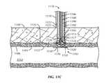
- FIGS. 11A-11Care schematic illustrations, in sequential order, of an introducer sheath and a delivery assembly delivering and deploying an implant assembly at a puncture site, as constructed in accordance with at least one embodiment of the present teachings.
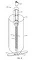
- FIG. 12is a schematic illustration of a kit including an implant assembly, a delivery assembly, an introducer sheath and a valve bypass, a dilator, and instructions for using these components to seal a puncture site or other opening in a blood vessel wall, body cavity or biopsy tract, as constructed in accordance with at least one embodiment of the present teachings.
- bioabsorbablerefers to the ability of a material to disintegrate or degrade so that no material remains after a predetermined period of time, such as after 1 week, after 5 years, or any period of time therebetween.
- distal and proximalrefer to a position or direction relative to a treating clinician. “Distal” and distal” refer to a position that is distant, or in a direction away, from the clinician. “Proximal” and “proximally” refer to a position that is closer to, or in a direction toward, the clinician.
- inner surface and outer surfacerefer to bodily tissue surfaces near a puncture or other opening.
- inner surfacerefers to an intra-luminal surface of a wall of a blood vessel or a wall of a body cavity.
- outer surfacerefers to an extra-luminal surface of a wall of a blood vessel or a wall of a body cavity.
- patientand “subject” refer to mammals and include both humans and animals.
- FIG. 1is a schematic illustration of a puncture 102 in a wall 104 of a blood vessel 106 (e.g., a femoral artery).
- the vessel 106is shown in cross-section passing beneath skin 108 and subcutaneous tissue 110 of a patient.
- the vessel 106has been accessed by way of a percutaneous surgical procedure, which has resulted in an access path 112 consisting of a tissue tract and the puncture 102 .
- the tract and puncture 102may have resulted from inserting an introducer assembly into a lumen 114 of the vessel 106 .
- the present closure systems, kits and methodscan be used to seal a puncture or another opening in a vessel wall, body cavity, or biopsy tract that has been created intentionally or unintentionally during a surgical procedure.
- Punctures made intentionallyinclude vascular punctures made in various types of vascular, endoscopic or orthopaedic surgical procedures, or punctures made in any other type of surgical procedure, in coronary or peripheral arteries and veins, or in a body cavity.
- Such proceduresinclude angiographic examination, angioplasty, laser angioplasty, valvuloplasty, atherectomy, stent deployment, rotablator treatment, aortic prosthesis implantation, aneurysm repair, ventricular-assist device deployment, intraortic balloon pump treatment, pacemaker implantation, any intra-cardiac procedure, electrophysiological procedures, interventional radiology, and various other diagnostic, prophylactic, and therapeutic procedures such as dialysis and procedures relating to percutaneous extracorporeal circulation.
- FIG. 2is a schematic illustration of an implant assembly 216 in its fully deployed configuration and sealing a puncture 202 in a wall 204 of a vessel 206 , as constructed in accordance with at least one embodiment. Sealing can be achieved by respectively applying inner 218 (intra-luminal) and outer 220 (extra-luminal) members of the implant assembly 216 against inner 222 and outer 224 vessel wall surfaces surrounding the puncture 202 .
- the inner member 218can be pulled against the inner surface 222 of the vessel wall 204 , and the outer member 220 can be pushed against the outer surface 224 of the vessel wall 204 so that the puncture 202 is contained or sandwiched between the members.
- the outer member 220can be deployed such that it expands between the inner 222 and outer 224 surfaces of the vessel wall 204 or at a position spaced from the outer surface 224 of the vessel wall 204 .
- the implant assembly 216can also include a sealing membrane 226 that extends from the inner member 218 and is configured at its proximal end 228 to receive the outer member 220 , which can expand to a sealing circumference larger than that of the puncture 202 .
- the presence of the sealing membrane 226allows the implant assembly 216 to be used to seal various puncture sizes, including small, medium and large punctures resulting from 8F-24F introducer sheaths, for example.
- the material of the sealing membrane in its mid-region 230can be caused to expand and conform to edges 239 of the puncture 202 .
- All components of the implant assembly 216can be made to be bioabsorbable. This ensures that the implant assembly 216 is absorbed into the patient after a predetermined period of time that is sufficient to permit biological repair of the vessel wall 204 and the tissue around the puncture 202 .
- the implanted componentsshould remain intact and slowly absorb or melt away, with no pieces coming loose and entering the blood stream. Further, it is desirable that the components initially maintain their strength and integrity so that the puncture 202 in the vessel wall 204 can begin to heal prior to the components beginning to weaken and absorb into the body.
- Bioabsorbable polymerssuch as polylactic acid (PLA), polyglycolic acid (PGA), trimethylene carbonate (TMC) and caprolactone (CL) can be used to form one or more of the components.
- Other suitable bioabsorbable polymersinclude, but are not limited to, poly D,L-lactide acid (PDLA), poly-L-lactic acid (PLLA), polyethylene glycol (PEG), polylactide-co-glycol acid (PLGA), polyanhydrides, polyorthoesters, polyethylene oxide (PEO), polydioxanone (PDS), polypropylene fumarate, polyethyl glutamate-co-glutamic acid, polytert-butyloxy-carbonylmethyl glutamate, polycaprolactone co-butylacrylate, polyhydroxybutyrate (PHBT) and copolymers of polyhydroxybutyrate, polyphosphazene, poly(D,L-lactide-co-caprolactone) (PLA/PCL),
- the components of the implant assembly 216can optionally be designed to provide the strength and absorption rate desired through the use of material combinations, over-molding or other coating techniques.
- the entire implant assembly 216 or specific portions of one or more of its componentscan be over molded, coated, or otherwise incorporate a second, third, etc. material to alter its strength or absorption profile.
- the second materialcan be an alkaline earth metal, such as magnesium.
- an acidic polymere.g., PLA
- the acidic nature of the polymercan maintain the pH in the vicinity of the magnesium below a critical level, such as below 8, thereby encouraging degradation.
- FIG. 3is an exploded view of an implant assembly 316 , as constructed in accordance with at least one embodiment.
- the implant assembly 316can comprise three primary components, namely, an inner member 318 , a sealing membrane 326 and an outer member 320 .
- the implant assembly 316can further comprise a connecting member 332 , which can optionally be incorporated into the inner member 318 , and a locking member 334 , which can optionally be incorporated into the outer member 320 .
- the components of the implant assembly 316can be placed and assembled in a distal-to-proximal manner (see, e.g., FIGS. 11A-11C ).
- the inner member 318can first be inserted through a puncture in a wall of a vessel and introduced into a lumen of the vessel. The inner member 318 can then be retracted until it is in contact with an inner surface of the vessel wall.
- the connecting member 332 and the sealing membrane 326can extend through the puncture, and the connecting member 332 can be used to hold the inner member 318 against the inner surface of the vessel wall.
- the outer member 320illustrated in its undeployed, delivery configuration—can then be received by the sealing membrane 326 —which can be in the form of a generally elongated tubular body with a closed or sealed distal end 336 and an open proximal end 328 —and advanced along the connecting member 332 until it contacts the outer surface of the vessel wall or until it contacts a stop member 341 placed along the length of the connecting member 332 .
- the stop member 341can provide a predetermined stop of the outer member 320 for closure of punctures such as apical access for mitral valve replacement in which there is a relatively long path to seal.
- Tensioncan be maintained on the connecting member 332 and a pushing force can be applied to the outer member 320 to expand its delivery configuration to a sealing configuration.
- the locking member 334can be secured to the connecting member 332 .
- the proximal end 328can have a closed or sealed proximal end 328 and the outer member 320 can be urged against the closed end.
- FIGS. 4 and 5are schematic illustrations of an inner member 418 , 518 and a connecting member 432 , 532 , as constructed in accordance with at least two embodiments.
- the connecting member 432 , 532can be a stem, rod, tube, string, thread or other filament that is part of the inner member 418 , 518 , or can be a stem, rod, tube, string, thread or other filament that is attached to the inner member 418 , 518 .
- FIG. 4illustrates a configuration in which the inner member 418 and the connecting member 432 are combined into a single molded piece.
- a hinge 438can be incorporated at the base of the connecting member 432 to allow the connecting member to bend or otherwise reorientate with respect to the inner member 418 .
- the hinge 438can be formed by notching the base of the connecting member 432 .
- FIG. 5illustrates a configuration in which the inner member 518 and the connecting member 532 are separate, but attachable pieces.
- the connecting member 532can be attached to the inner member 518 using a dissolvable suture 540 , a mechanical fastener, adhesive or any other suitable joining means.
- the inner 518 and connecting 532 membersmay or may not be comprised of the same bioabsorbable material or material combination.
- the inner member 418 , 518can be configured to be extended through a puncture in a wall of a vessel and into a lumen of the vessel to at least partially block the internal opening of the puncture. As illustrated in FIGS. 4 and 5 , the inner member 418 , 518 can have an enlarged central region 442 , 542 , positioned between first 444 , 544 and second 446 , 546 end regions, where it attaches to the connecting member 432 , 532 . This enlarged region 442 , 542 can provide a sufficient area to cover the internal opening of the puncture.
- a longitudinal axis 448 , 548can define a lengthwise dimension and transverse axes 450 , 550 can define widthwise dimensions.
- the lengthwise dimensioncan range from about 10 mm to about 20 mm, for example.
- the widthwise dimension at the end regionscan range from about 3 mm to about 5 mm, for example.
- the widthwise dimensioncan progressively increase so that its maximum width ranges from about 4 mm to about 8 mm, for example.
- the inner member 418 , 518can be composed of a thin, narrow strip or bar of material that is sufficiently rigid to be resistant to deformation, yet thin enough to conform to the inner surface of the vessel wall and not take up a substantial portion of the lumen of the vessel. It can be important for the inner member 418 , 518 to be resistant to deformation to preclude it from bending and passing back through the puncture in which it was introduced. It can also be important that in its final in situ position, as illustrated in FIG. 2 , the inner member 418 , 518 does not block or otherwise impede the flow of blood through the vessel. Since the component can be formed of a resorbable material, it can be left in pace within the body until it is absorbed.
- the inner member 418 , 518can be asymmetrically-shaped and include radiopaque marking elements 452 , 552 to help a treating clinician position it within a vessel.
- the inner member 418 , 518can include a first end region 444 , 544 that is longer than a second end region 446 , 546 to encourage pivoting about its attachment location to the connecting member 432 , 532 when deployed from an introducer sheath.
- the first end region 444 , 544can be about 1 ⁇ 3 longer than the second end region 446 , 546 .
- the inner member 418 , 518can also include the radiopaque marking elements 452 , 552 or a coating that is viewable on x-ray making visualization during delivery and deployment possible.
- the radiopaque materialcan be sodium diatrizoate, iopamidol, iohexol, iodixanol, iopromide, or another water soluble material, for example, and can be added to the material or material combination from which the inner member is composed or encapsulated in one or more pockets therein.
- the radiopaque marking elements 452 , 552are encapsulated within each of the first 444 , 544 and second 446 , 546 end regions of the inner member 418 , 518 .
- the radiopaque materialcan be non-water soluble, such as tungsten and platinum, and in the form of particles, washers, or wires (longitudinal or circumferential).
- the connecting member 432 , 532can have a length and cross-sectional size that allows it to fit through the puncture of the vessel wall. It can be desirable for the connecting member to have a length of at least about 38 mm (pre-cut) and at least about 9 mm (post-cut), such as between about 5 mm and about 60 mm, for example.
- the connecting member 432 , 532can have a constant or varying cross-sectional size.
- the connecting member 432 , 532can have a perpendicular or angled orientation relative to the inner member 418 , 518 in the absence of external forces (e.g., delivery forces from a wall of an introducer sheath).
- a number of pawls 454 , 554 or other spaced elementscan be formed on an outer surface of the connecting member 432 , 532 .
- the pawls 454 , 554can be spaced from each other in the longitudinal direction of the connecting member 432 , 532 .
- the presence of these spaced pawls 454 , 554can allow for adjusting the distance between a proximal end of an outer member (see, e.g., FIGS. 7A and 7B ) and a proximal end of the inner member 418 , 518 .
- the outer membercan be pushed against the outer surface of the vessel wall or a stop member (see, e.g., element 341 of FIG. 3 ) by urging the proximal end of the outer member in a distal direction toward the proximal end of the inner member 418 , 518 .
- a locking membercan provide resistance and prevent the proximal end of the outer member from retracting proximally and disengaging from the vessel wall or stop member.
- FIG. 6is a schematic illustration of a sealing membrane 626 attached to an inner member 618 on its distal end 636 and surrounding portions of a connecting member 632 along its mid-region and proximal end portions, as constructed in accordance with at least one embodiment.
- the distal end 636 of the sealing membrane 626can be located within or near an inner surface of the puncture, while the proximal end can be located outside of an outer surface of the puncture and can include an opening through which an outer member can be received.
- the distal end of the sealing membranecan be slid over a boss on an upper surface of the inner member 618 and pinched in an undercut section using an absorbable suture or O-ring 658 , for example.
- the distal end 636 of the sealing membrane 626can be inserted through a center hole of the inner member 618 and pinched in placed by a tapered plug member.
- the sealing membrane 626can be secured to the inner member 618 using a medical-grade adhesive, thermal or solvent bonding, or any other suitable joining means.
- the sealing membrane 626can be formed of a flexible, fluid impermeable and biodegradable polymer having an inner diameter or about 2 mm or more, a wall thickness in a range of about 0.025 mm to about 0.38 mm, and which can be cut to have a length of at least about 10 mm, for example.
- the sealing membrane 626is formed of STRATAPRENE® 3534 copolymer material, which is commercially available from Poly-Med, Inc., of Anderson, S.C. Because the sealing membrane 626 can be constructed from a flexible material, it is capable of expanding and contracting to accommodate changes in the size and shape of the outer member (e.g., during its change from a delivery configuration to a sealing configuration). In addition, because the outer member is larger than the diameter of the puncture in its deployed, sealing configuration, the mid-region of the sealing membrane 626 can continuously remain in contact with edges of the puncture and prevent blood leakage.
- FIGS. 7A and 7Bare schematic illustrations of an outer member 720 that can be expanded from a delivery configuration ( FIG. 7A ) to a sealing configuration ( FIG. 7B ), as constructed in accordance with at least one embodiment.
- the low profile of the delivery configurationcan be useful to facilitate delivery of the outer member 720
- the sealing configurationcan be useful to facilitate firmly lodging the outer member 720 in a tissue tract and sealing a puncture against outward blood flow.
- a diameter 756 of the outer member 720 in the sealing configuration ( FIG. 7B )is at least three times the diameter 756 of the outer member 720 in the delivery configuration ( FIG. 7A ). This can allow the outer member 720 , when in the sealing configuration, to cover the puncture and neighboring portions of the puncture from outside of the blood vessel wall.
- the outer member 720can be formed from a substantially rigid body with a generally cylindrical or polygonal (e.g., square or hexagonal) shape and having a proximal end 760 , an intermediate deformation portion 762 , and a distal end 764 .
- the bodycan have a pre-expanded, delivery length between about 6 mm and about 20 mm, and a pre-expanded, delivery diameter between about 2.5 mm and 20 mm, for example. Other shapes and dimensions are also possible.
- the intermediate deformation portion 762 of the outer member 720can include support struts 766 created by parallel slits or cuts 768 completely or partially through the wall of the member.
- the center portions of the support struts 766can move radially outward in a hinge-like manner in response to the movement of the member's proximal end 760 toward its distal end 764 .
- the struts 766 of the intermediate deformation portion 762can be elongated in a direction substantially perpendicular to an in situ inner member, while in the sealing configuration, the struts 766 can be contracted in a direction substantially parallel to the in situ inner member.
- a hinge 770 near the center of the struts 766can be formed in a variety of ways, including mechanical thinning, denting, grinding, heat forming or machining, or a weakened section created by micro cuts or tapered grooves.
- the number, length and distance between the slits or cuts 768can affect both the anchorability of the outer member 720 and the collapsibility of the member.
- the slits or cutscan be helical or serpentine such that they are adapted to expand and form wings upon rotation of the member's proximal end 760 relative to its distal end 764 .
- the slits or cuts 768 in the intermediate deformation portion 762 of the outer member 720can be formed using an etching or cutting process.
- the slitscan be cut along the intermediate portion of the rigid body using a cutting tool, such as a razor blade.
- the slitsare cut without removing any significant amount of material from the rigid body, i.e., the formation of the slits does not significantly reduce the overall volume of rigid body.
- the slitsare formed by cutting material out of the rigid body such that its volume is reduced.
- each slit 768can be rounded so-as-to relieve stresses at the axial ends of the slit. This can prevent the slits from lengthening due to stress.
- rounded endscan be produced by burning holes at both ends of each slit.
- rounded endscan be formed during the cutting process. The size of the rounded ends can vary depending upon the dimensions of the rigid body and the amount of stress release required.
- the outer member 720can be disposed within the lumen of a sealing membrane and received over and slid along a connecting member so that the distance between the outer member and the inner member is adjustable in an aligned manner, depending on a puncture or opening to be sealed. This makes it possible to cope with a variety of situations or cases, such as a patient with a thick, thin, hard or soft in vivo vessel wall.
- the sealing membranecan exert counteractive or countervailing contractile forces on the outer member. In this way, the sealing membrane does not expand passively, but rather, the outer member 720 forcibly expands the sealing membrane to cause the membrane to be taunt and capable of sealing the puncture in a fluid tight manner.
- the sealing membranecan be sized and shaped such that the outer member 720 expands to its sealing configuration to fill the space within the sealing membrane.
- the expanded diameters of the outer members 720can decrease in size as the distance from the treatment site (e.g., vessel wall puncture) increases.
- FIGS. 8A, 8B and 9are schematic illustrations of a locking member 834 , 934 that can be received by a proximal end of a connecting member 932 , as constructed in accordance with at least two embodiments.
- the locking member 834 , 934can be slid along the connecting member and into abutment against a proximal end of an outer member, thereby maintaining an in situ position of an inner member against an inner surface of a vessel wall, an expanded configuration of an outer member against an outer surface of the vessel wall or a stop member (see, e.g., element 341 of FIG. 3 ), and contact between a sealing membrane and edges of a puncture (as illustrated in FIG. 2 ) or tissue tract.
- Portions of the connecting member proximal to the locking membercan be cut using a mechanical means (e.g., shearing arrangement) or thermal means and removed after the locking member 834 , 934 has been secured to the connecting member.
- the locking member 834 , 934can take a variety of forms, non-limiting examples of which are provided in FIGS. 8A, 8B and 9 .
- the locking member 834 , 934can assume numerous other configurations while retaining its capability to maintain a position of the inner and outer members.
- FIGS. 8A and 8Billustrate a configuration in which the locking member 834 comprises a notched passageway 874 that is slidable and receives a number of pawls or other spaced elements formed on an outer surface of the connecting member in one direction, but is resistant to sliding of the pawls or other spaced elements in a second, opposite direction.
- the locking member 934comprises a compressible disk that is slidable and receives a connecting member 932 in the form of a filament having a plurality of ball projections 954 thereon.
- the filamenthaving a plurality of ball projections 954 thereon.
- one or more ball projections 954can pass through a central lumen of the disk to lock a position of the filament.
- FIGS. 8A, 8B and 9illustrate distinct locking members
- the locking membercan optionally be integrated into a portion of the outer member, such as at its proximal end.
- FIG. 10Ais a schematic cross-sectional illustration of a proximal portion of a delivery assembly 1076 configured to deploy an implant assembly at a puncture site, as constructed in accordance with at least one embodiment.
- FIG. 10Bis a schematic cross-sectional illustration of an implant assembly 1016 mounted on a distal portion of the delivery assembly 1076 , as constructed in accordance with at least one embodiment.
- the delivery assembly 1076can extend from a handle 1078 , operable by a treating clinician, at its proximal portion to connections with components of the implant assembly 1016 at its distal portion.
- the handle 1078can include a proximal housing portion 1080 and a distal housing portion 1082 .
- a handle lock 1084which can be activated during initial delivery steps, prevents relative movement between the two housing portions 1080 , 1082 . When the lock 1084 is not activated, the two housing portions 1080 , 1082 can be rotated relative to one another.
- Four elongate memberscan extend distally from the handle 1078 to the implant assembly 1016 , namely (moving from inside-out), a rail 1086 , a shear tube 1088 , a push tube 1090 , and a delivery tube 1092 .
- the rail 1086 and the shear tube 1088can be engaged with the proximal housing portion 1080 on their proximal ends.
- the rail 1086can extend from a proximal end 1094 , which is statically coupled with the proximal housing portion 1080 , to a distal end 1096 , which is engaged with an inner member 1018 of the implant assembly 1016 .
- the rail 1086can include a stainless steel ribbon having a rectangular cross-section.
- the proximal end of the ribboncan be secured in a rectangular pocket in the proximal housing portion 1080 .
- the distal end of the ribboncan be molded into a proximal end of a connecting member 1032 of the implant assembly 1016 .
- the connecting member 1032attaches to the inner member 1018 on its distal end.
- the connecting member 1032can include a rectangular cross-section slightly larger than that of the rail 1086 .
- the shear tube 1088can extend from a proximal end 1098 , which is engaged with an axial tract 1001 and an actuation member 1003 of the proximal housing portion 1080 , to a distal end 1005 , which includes a keyed passageway and abuts locking 1034 and outer 1020 members of the implant assembly 1016 .
- the axial tract 1001can ensure that the shear tube 1088 can only move axially relative to the proximal housing portion 1080 , with such axial movement being created through movement of the actuation member 1003 .
- the actuation member 1003includes a rotatable knob engaged with a threaded shaft 1007 .
- Rotation of the knob in a first directionurges distal movement of the threaded shaft 1007 .
- the distal movement of the threaded shaft 1007causes distal movement of the shear tube 1088 , which can transfer such movements (via push tube 1090 ) to the locking 1034 and outer 1020 members of the implant assembly 1016 .
- the push tube 1090 and the delivery tube 1092can be engaged with the distal housing portion 1082 on their proximal ends.
- the push tube 1090can extend from a proximal end 1009 , which is engaged with an axial tract 1011 of the distal housing portion 1082 such that the tube can only move axially relative to the distal housing portion, to a distal end 1013 , which includes a keyed passageway similar in size and shape to the keyed passageway of the shear tube 1088 .
- the push tube 1090surrounds portions of the shear tube 1088 and its distal end 1013 extends distal to the distal end 1005 of the shear tube.
- the push tube 1090is also moved distally.
- the keyed passageways of the shear 1088 and push 1090 tubescan be configured to receive and slide along the rail 1086 and the connecting 1032 member.
- the delivery tube 1092can concentrically surround portions of the push tube 1090 and the shear tube 1088 .
- the delivery tube 1092can be statically coupled with the distal housing portion 1082 ; on its distal end 1017 , an outer surface of the delivery tube 1092 can be statically coupled to a proximal end 1028 of a sealing membrane 1026 of the implant assembly 1016 .
- the distal end 1017 of the delivery tube 1092Prior to distal movement of the shear 1088 and push 1090 tubes, the distal end 1017 of the delivery tube 1092 can be positioned distal to the distal ends 1005 , 1013 of the shear and push tubes, thereby creating an internal cavity 1019 for placement of the locking 1034 and outer 1020 members during initial delivery. After distal movement of the shear 1088 and push 1090 tubes, the distal end 1017 of the delivery tube 1092 can be positioned proximal to the distal ends 1005 , 1013 of the shear and push tubes.
- the handle 1078can include certain features to ease manufacturing and use.
- the handle 1078can include a clamshell-like configuration including four pieces (two for each of the proximal and distal housing portions) allowing for the placement of proximal ends of the four elongate members during manufacture.
- a distal end of the handle 1078can include engagement features (e.g., snap lock arms) configured to detachable couple to a proximal end of an introducer sheath.
- an outer surface portion of the handle 1078can include a flat surface, visible marking or other indicator means that conveys an orientation of the distally-positioned implant assembly 1016 to the treating clinician.
- FIGS. 11A-11Care schematic illustrations, in sequential order, of an introducer sheath 1119 and a delivery assembly 1176 delivering and deploying an implant assembly 1116 at a puncture site 1102 , as constructed in accordance with at least one embodiment.
- the delivery assembly 1176may take other suitable configurations, but will be described in association with the configuration illustrated and described in FIGS. 10A and 10B .
- a dilator(not shown) can be inserted through the introducer sheath 1119 and over a guidewire (not shown) into a vessel lumen 1114 such that portions of the introducer sheath 1119 and dilator extend through an opening in a patient's skin 1108 , through a tissue tract, through the puncture 1102 and into the vessel lumen 1114 .
- the location of the introducer sheath's distal end 1121can be verified using a radiopaque marker band 1123 embedded or otherwise attached to the sheath.
- the guidewire and dilatorcan be withdrawn, and distal portions of the delivery assembly 1176 can be inserted into a proximal end of the introducer sheath 1119 using a valve bypass (not shown) and advanced toward the distal end 1121 of the introducer sheath, as illustrated in FIG. 11A .
- An inner member 1118 of the implant assembly 1176can be retained in a longitudinal, axially-aligned orientation by a wall of the introducer sheath 1119 during this advancement.
- the delivery assembly 1176can be further advanced through the introducer sheath 1119 and past its distal tip 1121 so that the inner member 1118 extends into the vessel lumen 1114 .
- the inner member 1118can be pivoted to a transverse orientation by way of a dimple (or concavity) 1125 at the distal end 1121 of the introducer sheath. This pivoting of the inner member 1118 can be further encouraged by an offset connection to a connecting member 1132 .
- the introducer sheath 1119can be pulled proximally and its proximal hub can be brought into engagement with snap lock arms on a distal end of a handle of the delivery assembly 1176 .
- This proximal pullingmoves the distal end 1121 of the introducer sheath 1119 away from the vicinity of the vessel wall 1104 , providing space for components of the implant assembly 1116 to be deployed, and locks the sheath to the delivery assembly 1176 so that they can be simultaneously removed at the end of a closure procedure.
- the handlecan be gently pulled proximally to urge the inner member 1118 against an inner surface 1122 of the vessel wall 1104 by way of a rail 1186 that can extend from a proximal housing portion to the connecting member 1132 engaged with the inner member 1118 .
- An enlarged region of the inner member 1118can be positioned to span the internal opening of the puncture 1102 .
- a knob on a proximal housing portioncan be rotated to move distal ends 1105 , 1113 of a shear tube 1188 and a push tube 1190 in a distal direction.
- This distal movementcan urge an outer member 1120 and a locking member 1134 of the implant assembly from a cavity within a distal end 1117 of a surrounding delivery tube 1192 , along the rail 1186 and proximal portions of the connecting member 1132 , and through a proximal lumen of a sealing membrane 1126 of the implant assembly 1116 so that the distance between the outer 1120 and inner 1118 members is reduced.
- Additional rotation of the knobcan cause the outer 1120 and locking 1134 members to move further along the connecting member 1132 , during which time a distal end of the outer member 1120 can contact an outer surface 1124 of the vessel wall 1104 (by way of the sealing membrane 1126 ), and the outer member 1120 can be caused to expand against the surrounding sealing membrane 1126 , as illustrated in FIG. 11C . Recoil of this outer member expansion can be precluded by the abutting locking member 1134 , which can be engaged with the connecting member 1132 .
- Portions of the connecting member 1132 proximal to the locking member 1134can now be cut and removed.
- a lock associated with the handlecan be unlocked to allow proximal and distal housing portions to be rotated relative to one another. Since the proximal end of the shear tube is rotatably secured to the proximal housing portion and the proximal end of the push tube is rotatably secured to the distal housing portion, relative rotation of the housing portions can cause corresponding relative rotation of the distal ends 1105 , 1113 of the shear 1188 and push 1190 tubes and their associated keyed passageways. This relative rotation of the keyed passageways can shear the connecting member 1132 so that its proximal portions can be removed.
- the sealing membrane 1126is attached to the inner member 1118 , can extend through portions of the puncture 1102 and surround portions of the outer member 1120 , and is attached to the distal end 1117 of the delivery tube 1192 at its proximal end (e.g., using UV adhesive, thermal bonding or solvent bonding).
- the handleLeveraging perforations (see, e.g., element 1031 in FIG. 10B ) in the sealing membrane 1126 , the handle can be pulled proximally to tear the sealing membrane 1126 along its perforations 1131 and separate the delivery tube 1192 from the implant assembly 1116 .
- the delivery assembly 1176 and the introducer sheath 1119can be removed from the patient by further pulling the handle proximally, in a direction away from the patient.
- FIG. 12is a schematic illustration of a kit 1233 including an implant assembly 1216 , a delivery assembly 1276 , an introducer sheath 1219 and a valve bypass 1235 , a dilator 1243 , and instructions 1237 for using these components to seal a puncture or other opening in a blood vessel wall, body cavity or biopsy tract, as constructed in accordance with at least one embodiment.
- the implant assembly 1216can come preloaded and attached to distal end portions of the delivery assembly 1276 . In this way, a treating clinician, after gaining access to a vessel lumen with the dilator 1243 and introducer sheath 1219 , can perform the series of simple steps described and illustrated in FIGS. 11A-11C to seal the puncture site.
- the dilator 1243can be relatively long (e.g., about 80 cm or more) and without a proximal hub to facilitate removal of a TAVI sheath or other interventional device, for example.
- the present closure systems, kits and methodscan be used by a treating clinician to seal a puncture or other opening following removal of an introducer sheath or other interventional device, regardless of whether the device's profile is small, medium or large in size.
- the systems, kits and methodsallow for closure of the puncture or opening using a construction that is easy to use, safe, effective and reliable.
- Implant components of a closure systemcan dissolve over a period of time while permitting healing of the puncture or opening and the surrounding tissue.
- a closure system for sealing a holewhich extends between a first tissue surface and a second tissue surface and has a size and an edge, comprises an implant assembly.
- the implant assemblycan include an inner member, an outer member and a sealing membrane.
- the inner membercan be configured to extend at least partially through the hole and have a surface positionable against the first tissue surface.
- the outer membercan expand from a delivery configuration to a sealing configuration and be positioned adjacent the second tissue surface.
- the sealing configurationcan have a size larger than the size of hole.
- the sealing membranecan have a distal end sealably attached to the inner member, a proximal end including an opening configured to receive the outer member, and a mid-region therebetween. The outer member, when in the sealing configuration, can urge the mid-region of the sealing membrane radially outward such that its outer surface contacts and conforms to the edge of the hole.
- Example 2the closure system of Example 1 can optionally be configured such that the implant assembly further comprises a connecting member coupled on its distal end to the inner member and extending at an angle relative to the inner member.
- the connecting membercan include one or more surface projections extending along a portion of its length.
- Example 3the closure system of Example 2 can optionally be configured such that the implant assembly further comprises a locking member including a projection engagement portion, which allows the connecting member to be slid with respect to the locking member in a first direction but precludes the connecting member from sliding with respect to the locking member in a second, opposite direction.
- Example 4the closure system of any one of Examples 2 or 3 can optionally be configured such that a hinge is incorporated at an intersection of the inner member and the connecting member.
- Example 5the closure system of any one or any combination of Examples 1-4 can optionally be configured such that the inner member includes an enlarged region between first and second end regions.
- the first end regioncan have a length greater than the second end region.
- Example 6the closure system of Example 5 can optionally be configured such that each of the first and second end regions includes a radiopaque material or a void that is viewable using fluoroscopy or ultrasound.
- Example 7the closure system of Example 6 can optionally be configured such that the radiopaque material is a water soluble material.
- Example 8the closure system of any one or any combination of Examples 1-7 can optionally be configured such that the outer member has a proximal end, an intermediate deformation portion, and a distal end.
- the intermediate deformation portioncan include a plurality of struts created by parallel slits or cuts through a wall of the outer member.
- Example 9the closure system of Example 8 can optionally be configured such that each of the plurality of struts includes a hinge region.
- Example 10the closure system of any one of Examples 8 or 9 can optionally be configured such that when the outer member is in the delivery configuration, each of the plurality of struts is elongated in a direction substantially perpendicular to the inner member.
- Example 11the closure system of any one or any combination of Examples 8-10 can optionally be configured such that when the outer member is in the sealing configuration, each of the plurality of struts is contracted in a direction substantially parallel to the inner member.
- Example 12the closure system of any one or any combination of Examples 8-11 can optionally be configured such that the size of the outer member in the sealing configuration is dependent on an amount of contraction of the plurality of struts.
- Example 13the closure system of any one or any combination of Examples 1-12 can optionally be configured such that each of the inner member, the outer member, and the sealing membrane includes a bioabsorbable material.
- Example 14the closure system of Example 13 can optionally be configured such that the bioabsorbable material includes an acidic polymer and an alkaline earth metal.
- Example 15the closure system of any one or any combination of Examples 1-14 can optionally be configured such that the sealing membrane includes a non-porous material.
- Example 16the closure system of any one or any combination of Examples 1-15 can optionally be configured such that the sealing membrane includes a micro-porous material having a plurality of micro-pores. Each micro-pore can be sized and shaped to inhibit the flow of blood cells.
- Example 17the closure system of any one or any combination of Examples 1-16 can optionally be configured such that the sealing membrane includes one or more reinforcing elements.
- Example 18the closure system of Example 17 can optionally be configured such that the one or more reinforcing elements are arranged parallel to a longitudinal axis of the sealing membrane.
- Example 19the closure system of Example 17 can optionally be configured such that the one or more reinforcing elements are arranged at an angle relative to a longitudinal axis of the sealing membrane.
- Example 20the closure system of any one or any combination of Examples 1-19 can optionally be configured such that the sealing membrane includes a non-uniform cross-sectional size between its distal end and its proximal end.
- Example 21the closure system of any one or any combination of Examples 1-20 can optionally be configured such that the sealing membrane includes one or more perforations near its proximal end.
- the closure system of any one or any combination of Examples 1-21can optionally further comprise a delivery assembly.
- the delivery assemblycan include a handle, a rail, a shear tube, a delivery tube and an actuation member.
- the handlecan have a first housing portion and a second housing portion.
- the railcan extend from a first end engaged with the inner member to a second end statically coupled with the second housing portion.
- the outer membercan be supported by the rail between its first and second ends.
- the shear tubecan extend from a first end, which includes a keyed passageway, to a second end engaged with the second housing portion.
- the delivery tubecan concentrically surround portions of the shear tube, be coupled to an end of the sealing membrane on its first end, and be coupled to the first housing portion on its second end.
- the actuation membercan be engaged with the second end of the shear tube to urge the tube in a direction to expand the outer member from its delivery configuration to its sealing configuration.
- Example 23the closure system of Example 22 can optionally be configured such that the first housing portion is releasably lockable to the second housing portion. In the absence of being locked, the first housing portion can rotate relative to the second housing portion.
- Example 24the closure system of any one of Examples 22 or 23 can optionally be configured such that the second end of the shear tube is engaged with an axial tract of the second housing portion, thereby confining the shear tube to axial movements relative to the second housing portion.
- Example 25the closure system of any one or any combination of Examples 22-24 can optionally be configured such that the delivery assembly further comprises a push tube positioned between the shear tube and the delivery tube.
- the push tubecan extend from a first end, which includes a keyed passageway, to a second end engaged with an axial tract of the first housing portion. This axial tract can confine the push tube to axial movements relative to the first housing portion.
- a method for sealing a hole that extends between an inner vessel surface and an outer vessel surfacecan comprise inserting an inner member through the hole and into a lumen of the vessel.
- the inner membercan be pulled against the inner vessel surface and portions of a connecting member and a sealing membrane, which are coupled on their first ends to the inner member, can be arranged to extend to the outside of the vessel on their second ends.
- An outer member in a delivery configurationcan then be inserted through the second end of the sealing membrane such that the sealing membrane at least partially surrounds the outer member.
- a compressive forcecan be applied to the outer member in a distal direction to expand the delivery configuration to a sealing configuration. This expansion can urge a mid-region of the sealing membrane radially outward such that its outer surface contacts and conforms to an edge of the hole.
- Example 27the method of Example 26 can optionally be configured such that applying the compressive force to the outer member includes expanding the outer member to a circumference greater than a perimeter of the hole.
- Example 28the method of any one of Examples 26 or 27 can optionally further comprise securing a position of the inner member against the inner vessel surface and the expansion of the outer member in the sealing configuration. This securing can include engaging a locking member with a portion of the connecting member.
- Example 29the method of Example 28 can optionally further comprise changing a circumference of the outer member in the sealing configuration by adjusting a position of the locking member relative to the connecting member.
- Example 30the method of any one of Examples 28 or 29 can optionally further comprise shearing portions of the connecting member that are proximal of the locking member.
- Example 31the method of any one or any combination of Examples 26-30 can optionally be configured such that inserting the outer member through the second end of the sealing membrane includes positioning the outer member into a portion of the sealing membrane having a larger cross-sectional size than other portions of the sealing membrane.
- Example 32the method of any one or any combination of Examples 26-31 can optionally further comprise viewing encapsulated pockets of iodine in the inner member using x-ray.
- Example 33the method of any one or any combination of Examples 26-32 can optionally further comprise removing excess portions of the sealing membrane along one or more perforations near its second end.
- Examplethe system or method of any one or any combination of Examples 1-33 can optionally be configured such that all elements or options recited are available to use or select from.
Landscapes
- Health & Medical Sciences (AREA)
- Surgery (AREA)
- Life Sciences & Earth Sciences (AREA)
- Medical Informatics (AREA)
- Nuclear Medicine, Radiotherapy & Molecular Imaging (AREA)
- Engineering & Computer Science (AREA)
- Biomedical Technology (AREA)
- Heart & Thoracic Surgery (AREA)
- Cardiology (AREA)
- Molecular Biology (AREA)
- Animal Behavior & Ethology (AREA)
- General Health & Medical Sciences (AREA)
- Public Health (AREA)
- Veterinary Medicine (AREA)
- Surgical Instruments (AREA)
- Prostheses (AREA)
Abstract
Description
Claims (16)
Priority Applications (3)
| Application Number | Priority Date | Filing Date | Title |
|---|---|---|---|
| US15/040,023US10016188B2 (en) | 2015-02-10 | 2016-02-10 | Closure device for sealing percutaneous opening in a vessel |
| US15/920,665US10722225B2 (en) | 2015-02-10 | 2018-03-14 | Closure device for sealing percutaneous opening in a vessel |
| US17/873,859USRE50585E1 (en) | 2015-02-10 | 2022-07-26 | Closure device for sealing percutaneous opening in a vessel |
Applications Claiming Priority (2)
| Application Number | Priority Date | Filing Date | Title |
|---|---|---|---|
| US201562114101P | 2015-02-10 | 2015-02-10 | |
| US15/040,023US10016188B2 (en) | 2015-02-10 | 2016-02-10 | Closure device for sealing percutaneous opening in a vessel |
Related Child Applications (2)
| Application Number | Title | Priority Date | Filing Date |
|---|---|---|---|
| US15/920,665DivisionUS10722225B2 (en) | 2015-02-10 | 2018-03-14 | Closure device for sealing percutaneous opening in a vessel |
| US17/873,859DivisionUSRE50585E1 (en) | 2015-02-10 | 2022-07-26 | Closure device for sealing percutaneous opening in a vessel |
Publications (2)
| Publication Number | Publication Date |
|---|---|
| US20160228109A1 US20160228109A1 (en) | 2016-08-11 |
| US10016188B2true US10016188B2 (en) | 2018-07-10 |
Family
ID=55640844
Family Applications (3)
| Application Number | Title | Priority Date | Filing Date |
|---|---|---|---|
| US15/040,023Active2036-11-19US10016188B2 (en) | 2015-02-10 | 2016-02-10 | Closure device for sealing percutaneous opening in a vessel |
| US15/920,665CeasedUS10722225B2 (en) | 2015-02-10 | 2018-03-14 | Closure device for sealing percutaneous opening in a vessel |
| US17/873,859Active2036-12-15USRE50585E1 (en) | 2015-02-10 | 2022-07-26 | Closure device for sealing percutaneous opening in a vessel |
Family Applications After (2)
| Application Number | Title | Priority Date | Filing Date |
|---|---|---|---|
| US15/920,665CeasedUS10722225B2 (en) | 2015-02-10 | 2018-03-14 | Closure device for sealing percutaneous opening in a vessel |
| US17/873,859Active2036-12-15USRE50585E1 (en) | 2015-02-10 | 2022-07-26 | Closure device for sealing percutaneous opening in a vessel |
Country Status (6)
| Country | Link |
|---|---|
| US (3) | US10016188B2 (en) |
| EP (2) | EP4147649A1 (en) |
| JP (1) | JP6641378B2 (en) |
| CN (1) | CN107249475B (en) |
| CA (1) | CA2975309C (en) |
| WO (1) | WO2016130610A2 (en) |
Cited By (5)
| Publication number | Priority date | Publication date | Assignee | Title |
|---|---|---|---|---|
| US11433216B2 (en) | 2018-09-17 | 2022-09-06 | Seigla Medical, Inc. | Methods for fabricating medical devices and portions of medical devices |
| US11547835B2 (en) | 2018-09-17 | 2023-01-10 | Seigla Medical, Inc. | Systems, methods and apparatus for guiding and supporting catheters and methods of manufacture |
| US11660420B2 (en) | 2018-09-17 | 2023-05-30 | Seigla Medical, Inc. | Catheters and related devices and methods of manufacture |
| WO2023150083A1 (en)* | 2022-02-02 | 2023-08-10 | Walters Greg A | Venous sealing apparatus and method of closing a venous access |
| US12383246B2 (en) | 2020-10-12 | 2025-08-12 | Abbott Cardiovascular Systems, Inc. | Vessel closure device with improved safety and tract hemostasis |
Families Citing this family (18)
| Publication number | Priority date | Publication date | Assignee | Title |
|---|---|---|---|---|
| US10485524B2 (en) | 2011-10-25 | 2019-11-26 | Essential Medical, Inc. | Instrument and methods for surgically closing percutaneous punctures |
| US9757104B2 (en) | 2012-07-19 | 2017-09-12 | Essential Medical, Inc. | Multi-lumen tamper tube |
| US10639019B2 (en) | 2013-03-15 | 2020-05-05 | Arrow International, Inc. | Vascular closure devices and methods of use |
| EP3858254B1 (en) | 2013-12-23 | 2024-04-24 | Teleflex Life Sciences LLC | Vascular closure device |
| EP4147649A1 (en) | 2015-02-10 | 2023-03-15 | Teleflex Life Sciences Limited | Closure device for sealing percutaneous opening in a vessel |
| US10555727B2 (en) | 2015-06-26 | 2020-02-11 | Essential Medical, Inc. | Vascular closure device with removable guide member |
| US10639020B2 (en) | 2015-09-28 | 2020-05-05 | M-V Arterica AB | Vascular closure device |
| US11020224B2 (en) | 2017-07-11 | 2021-06-01 | Teleflex Life Sciences Limited | Methods for exchanging devices |
| US10668253B2 (en) | 2017-07-11 | 2020-06-02 | Teleflex Life Sciences Limited | Methods for exchanging devices |
| US11179145B2 (en)* | 2017-11-16 | 2021-11-23 | M-V Arterica AB | Collapsible tube for hemostasis |
| US20190142403A1 (en) | 2017-11-16 | 2019-05-16 | M-V Arterica AB | Tissue closure device |
| EP3870076A4 (en) | 2018-10-24 | 2022-08-10 | Arterica Inc. | SELF-EXPANDING HEMOSTATIC DEVICES AND METHODS FOR FASCIAL AND VASCULAR PASSAGES |
| CN111150433B (en)* | 2018-11-08 | 2024-12-31 | 先健科技(深圳)有限公司 | Occluder |
| EP4061244A4 (en) | 2019-11-19 | 2024-06-19 | Arterica Inc. | VASCULAR CLOSURE DEVICES AND METHODS |
| CN111150891B (en)* | 2020-02-03 | 2025-01-14 | 陈阜东 | Anti-leakage drainage tube |
| US12390249B2 (en) | 2020-07-31 | 2025-08-19 | Teleflex Life Sciences Llc | Access sheath with valve assembly |
| CN113069153B (en)* | 2021-05-19 | 2024-07-02 | 资阳市中心医院 | Plugging device for breach on arterial vessel |
| CN116584998A (en)* | 2023-05-17 | 2023-08-15 | 上海恩盛医疗科技有限公司 | A multi-stage positioning controllable blood vessel closure device and delivery system |
Citations (116)
| Publication number | Priority date | Publication date | Assignee | Title |
|---|---|---|---|---|
| US5108420A (en)* | 1991-02-01 | 1992-04-28 | Temple University | Aperture occlusion device |
| US5222974A (en)* | 1991-11-08 | 1993-06-29 | Kensey Nash Corporation | Hemostatic puncture closure system and method of use |
| US5282827A (en)* | 1991-11-08 | 1994-02-01 | Kensey Nash Corporation | Hemostatic puncture closure system and method of use |
| US5350399A (en)* | 1991-09-23 | 1994-09-27 | Jay Erlebacher | Percutaneous arterial puncture seal device and insertion tool therefore |
| USRE34866E (en)* | 1987-02-17 | 1995-02-21 | Kensey Nash Corporation | Device for sealing percutaneous puncture in a vessel |
| US5411520A (en)* | 1991-11-08 | 1995-05-02 | Kensey Nash Corporation | Hemostatic vessel puncture closure system utilizing a plug located within the puncture tract spaced from the vessel, and method of use |
| US5486195A (en)* | 1993-07-26 | 1996-01-23 | Myers; Gene | Method and apparatus for arteriotomy closure |
| US5531759A (en)* | 1994-04-29 | 1996-07-02 | Kensey Nash Corporation | System for closing a percutaneous puncture formed by a trocar to prevent tissue at the puncture from herniating |
| US5556376A (en)* | 1988-07-22 | 1996-09-17 | Yoon; Inbae | Multifunctional devices having loop configured portions and collection systems for endoscopic surgical procedures and methods thereof |
| US5620461A (en)* | 1989-05-29 | 1997-04-15 | Muijs Van De Moer; Wouter M. | Sealing device |
| US5662681A (en)* | 1996-04-23 | 1997-09-02 | Kensey Nash Corporation | Self locking closure for sealing percutaneous punctures |
| US5676689A (en)* | 1991-11-08 | 1997-10-14 | Kensey Nash Corporation | Hemostatic puncture closure system including vessel location device and method of use |
| US5700277A (en)* | 1993-06-04 | 1997-12-23 | Kensey Nash Corporation | Hemostatic vessel puncture closure with filament lock |
| US5782860A (en) | 1997-02-11 | 1998-07-21 | Biointerventional Corporation | Closure device for percutaneous occlusion of puncture sites and tracts in the human body and method |
| US5853422A (en)* | 1996-03-22 | 1998-12-29 | Scimed Life Systems, Inc. | Apparatus and method for closing a septal defect |
| US5861003A (en)* | 1996-10-23 | 1999-01-19 | The Cleveland Clinic Foundation | Apparatus and method for occluding a defect or aperture within body surface |
| US5925060A (en) | 1998-03-13 | 1999-07-20 | B. Braun Celsa | Covered self-expanding vascular occlusion device |
| US5976174A (en) | 1997-12-15 | 1999-11-02 | Ruiz; Carlos E. | Medical hole closure device and methods of use |
| US6071300A (en) | 1995-09-15 | 2000-06-06 | Sub-Q Inc. | Apparatus and method for percutaneous sealing of blood vessel punctures |
| US6080182A (en)* | 1996-12-20 | 2000-06-27 | Gore Enterprise Holdings, Inc. | Self-expanding defect closure device and method of making and using |
| US6183496B1 (en) | 1998-11-02 | 2001-02-06 | Datascope Investment Corp. | Collapsible hemostatic plug |
| US6190400B1 (en)* | 1991-10-22 | 2001-02-20 | Kensey Nash Corporation | Blood vessel sealing device and method of sealing an opening in a blood vessel |
| US6328757B1 (en) | 1999-04-23 | 2001-12-11 | Robert G. Matheny | Device and method for performing surgery without impeding organ function |
| US6331184B1 (en) | 1999-12-10 | 2001-12-18 | Scimed Life Systems, Inc. | Detachable covering for an implantable medical device |
| US6425911B1 (en)* | 2001-05-09 | 2002-07-30 | Radi Medical Systems Ab | Positioning device and incision closure device |
| US20020173820A1 (en)* | 2001-05-03 | 2002-11-21 | Radi Medical Systems Ab | Guiding tool for wound closure element |
| US20020198562A1 (en)* | 2000-04-19 | 2002-12-26 | Radi Medical Systems Ab | Reinforced absorbable medical sealing device |
| US6508828B1 (en)* | 2000-11-03 | 2003-01-21 | Radi Medical Systems Ab | Sealing device and wound closure device |
| US20030023267A1 (en)* | 2000-12-14 | 2003-01-30 | Core Medical, Inc. | Guide wire element for positioning vascular closure devices and methods for use |
| US20030050665A1 (en)* | 2001-09-07 | 2003-03-13 | Integrated Vascular Systems, Inc. | Needle apparatus for closing septal defects and methods for using such apparatus |
| US20040093025A1 (en)* | 2002-10-25 | 2004-05-13 | Radi Medical Systems Ab | Absorbable medical sealing device |
| US6860895B1 (en)* | 1999-06-18 | 2005-03-01 | Radi Medical Systems Ab | Tool, a sealing device, a system and a method for closing a wound |
| US20060009800A1 (en)* | 2003-04-11 | 2006-01-12 | Velocimed Pfo, Inc. | Closure devices, related delivery methods, and related methods of use |
| US20060173492A1 (en)* | 2003-07-03 | 2006-08-03 | Radi Medical Systems Ab | Wound closure and sealing device |
| US20060241579A1 (en)* | 2003-12-26 | 2006-10-26 | Terumo Kabushiki Kaisha | Tissue closure and tissue closing device |
| US20060265008A1 (en)* | 2005-05-18 | 2006-11-23 | Terumo Kabushiki Kaisha | Tissue closing device |
| US7144410B2 (en) | 2003-09-18 | 2006-12-05 | Cardia Inc. | ASD closure device with self centering arm network |
| US20070031508A1 (en)* | 2005-06-21 | 2007-02-08 | Armstrong David N | Implantable graft to close a fistula |
| US20070083232A1 (en)* | 2005-10-07 | 2007-04-12 | Innovasive, Inc. | Vascular closure device |
| US20070135842A1 (en)* | 1991-10-22 | 2007-06-14 | Kensey Nash Corporation | Sealing device |
| US20080091235A1 (en)* | 2006-10-11 | 2008-04-17 | Sirota Daniel J | Closure device with biomaterial patches |
| US20080097509A1 (en)* | 2003-12-15 | 2008-04-24 | Mordechay Beyar | Biodegradable Closure Device |
| US20090143815A1 (en)* | 2007-11-30 | 2009-06-04 | Boston Scientific Scimed, Inc. | Apparatus and Method for Sealing a Vessel Puncture Opening |
| US20090171281A1 (en)* | 2007-12-31 | 2009-07-02 | Pipenhagen Catherine A | Systems and methods for locating and closing a tissue puncture |
| US20090216267A1 (en)* | 2008-02-26 | 2009-08-27 | Boston Scientific Scimed, Inc. | Closure device with rapidly dissolving anchor |
| US20090234377A1 (en)* | 2008-03-14 | 2009-09-17 | Radi Medical Systems Ab | Medical closure device |
| US20090270885A1 (en)* | 2005-09-29 | 2009-10-29 | Terumo Kabushiki Kaisha | Tissue closing device |
| US7621937B2 (en)* | 2003-12-03 | 2009-11-24 | St. Jude Medical Puerto Rico LC | Vascular sealing device with high surface area sealing plug |
| US7658748B2 (en)* | 2003-09-23 | 2010-02-09 | Cardia, Inc. | Right retrieval mechanism |
| US20100087854A1 (en)* | 2008-08-12 | 2010-04-08 | Joshua Stopek | Medical device for wound closure and method of use |
| US20100100107A1 (en) | 2008-10-20 | 2010-04-22 | IMDS, Inc. | Systems and methods for cerebrospinal fluid repair |
| US20100217308A1 (en)* | 2009-02-20 | 2010-08-26 | Boston Scientific Scimed, Inc. | Locking element for vascular closure device |
| US20100217311A1 (en)* | 2009-02-20 | 2010-08-26 | Boston Scientific Scimed, Inc. | Tissue puncture closure device |
| US20100256673A1 (en)* | 2006-02-03 | 2010-10-07 | James Coleman | Wound Closure Devices and System |
| US20100275432A1 (en)* | 2009-02-20 | 2010-11-04 | Boston Scientific Scimed, Inc. | Locking element for vascular closure device |
| US7875052B2 (en)* | 2004-12-17 | 2011-01-25 | Terumo Kabushiki Kaisha | Tissue closure and tissue closing device |
| US20110029012A1 (en)* | 2009-07-28 | 2011-02-03 | St. Jude Medical Puerto Rico Llc | Dual hypotube suture cutting device and methods |
| US20110066181A1 (en)* | 2009-02-20 | 2011-03-17 | Boston Scientific Scimed, Inc. | Tissue puncture closure device |
| US7931671B2 (en) | 2005-03-11 | 2011-04-26 | Radi Medical Systems Ab | Medical sealing device |
| US20110196388A1 (en)* | 2010-02-11 | 2011-08-11 | Boston Scientific Scimed, Inc. | Automatic vascular closure deployment devices and methods |
| US8029522B2 (en)* | 2005-08-05 | 2011-10-04 | Ethicon Endo-Surgery, Inc. | Method and apparatus for sealing a gastric opening |
| US8057510B2 (en) | 2000-12-14 | 2011-11-15 | Ensure Medical, Inc. | Plug with collet and apparatus and method for delivering such plugs |
| US8070772B2 (en)* | 2008-02-15 | 2011-12-06 | Rex Medical, L.P. | Vascular hole closure device |
| US8083768B2 (en) | 2000-12-14 | 2011-12-27 | Ensure Medical, Inc. | Vascular plug having composite construction |
| US20120022562A1 (en)* | 2010-07-23 | 2012-01-26 | Boston Scientific Scimed, Inc. | Device to detect internal bleeding |
| US8105352B2 (en)* | 2004-12-16 | 2012-01-31 | Radi Medical Systems Ab | Medical sealing device |
| US20120065667A1 (en) | 2010-07-02 | 2012-03-15 | Alex Javois | Left atrial appendage occlusion device |
| US20120089177A1 (en)* | 2010-10-08 | 2012-04-12 | St. Jude Medical Puerto Rico LLC. | Cam driven compaction tube for vascular closure device |
| US20120116447A1 (en)* | 2010-05-19 | 2012-05-10 | Cleon Stanley | Devices and methods useful for sealing bodily openings |
| US8192456B2 (en)* | 2009-07-13 | 2012-06-05 | Vascular Solutions, Inc. | Metal vascular aperture closure device |
| US20120143245A1 (en)* | 2009-08-14 | 2012-06-07 | St. Jude Medical Puerto Rico Llc | Carrier tube for vascular closure device and methods |
| US20120158044A1 (en)* | 2010-12-17 | 2012-06-21 | Boston Scientific Scimed, Inc. | Tissue puncture closure device |
| US20120209323A1 (en)* | 2011-01-19 | 2012-08-16 | Accessclosure, Inc. | Apparatus and methods for sealing a vascular puncture |
| US8267959B2 (en)* | 2003-12-19 | 2012-09-18 | Radi Medical Systems Ab | Technique for securing a suture |
| US8323305B2 (en) | 1997-02-11 | 2012-12-04 | Cardiva Medical, Inc. | Expansile device for use in blood vessels and tracts in the body and method |
| US20130006297A1 (en)* | 2011-06-30 | 2013-01-03 | William Joseph Drasler | Large Vessel Closure Sheath |
| US20130041395A1 (en)* | 2011-08-09 | 2013-02-14 | Didier De Canniere | Introductory assembly and method for inserting intracardiac instruments |
| US8382795B2 (en)* | 2003-12-03 | 2013-02-26 | St. Jude Medical Puerto Rico Llc | Vascular puncture seal anchor nest |
| US8398676B2 (en)* | 2008-10-30 | 2013-03-19 | Abbott Vascular Inc. | Closure device |
| US20130138149A1 (en)* | 2011-11-28 | 2013-05-30 | St. Jude Medical Puerto Rico Llc | Large bore anchor device |
| US8480706B2 (en) | 2003-07-14 | 2013-07-09 | W.L. Gore & Associates, Inc. | Tubular patent foramen ovale (PFO) closure device with catch system |
| US8500776B2 (en)* | 2010-02-08 | 2013-08-06 | Covidien Lp | Vacuum patch for rapid wound closure |
| US20130274795A1 (en) | 2012-02-29 | 2013-10-17 | Vivasure Medical Limited | Devices and methods for delivering implants for percutaneous perforation closure |
| US8597324B2 (en) | 1999-09-13 | 2013-12-03 | Rex Medical L.P. | Vascular hole closure device |
| US20140052171A1 (en)* | 2012-08-15 | 2014-02-20 | St. Jude Medical Puerto Rico Llc | Vascular closure device anchor |
| US8685059B2 (en)* | 2010-06-08 | 2014-04-01 | Essential Medical Llc | Self-locking closure device for percutaneously sealing punctures |
| US20140114346A1 (en)* | 2012-10-23 | 2014-04-24 | Medtronic, Inc. | Transapical Entry Point Closure Device |
| US20140114347A1 (en)* | 2012-10-19 | 2014-04-24 | Cook Medical Technologies Llc | Vascular closure with multiple connections |
| US20140142620A1 (en)* | 2012-11-19 | 2014-05-22 | Cook Medical Technologies Llc | Degradable balloon device and method for closure of openings in a tissue wall |
| US8747435B2 (en) | 2005-12-13 | 2014-06-10 | Cardiva Medical, Inc. | Drug eluting vascular closure devices and methods |
| US20140163608A1 (en)* | 2012-12-10 | 2014-06-12 | Peter Osypka Stiftung | Implantable sealing device |
| US20140172012A1 (en)* | 2012-12-13 | 2014-06-19 | Cook Medical Technologies Llc | Vascular closure device suture tension mechanism |
| US20140194925A1 (en) | 2011-05-18 | 2014-07-10 | St. Jude Medical Puerto Rico Llc | Method and system for closing a vascular hole |
| US20140207184A1 (en)* | 2013-01-21 | 2014-07-24 | John I. Shipp | Vessel Sealing Device |
| US20140207183A1 (en)* | 2013-01-21 | 2014-07-24 | John I. Shipp | Vessel Sealing Device with Automatic Deployment |
| US20140222064A1 (en)* | 2013-02-01 | 2014-08-07 | St. Jude Medical Puerto Rico Llc | Dual lumen carrier tube with retractable sleeve and methods |
| US20140236225A1 (en)* | 2013-02-21 | 2014-08-21 | St. Jude Medical Puerto Rico Llc | Bioadhesive delivery systems and methods for vascular closure |
| US20140236224A1 (en)* | 2013-02-21 | 2014-08-21 | St. Jude Medical Puerto Rico Llc | Detachable sealing plug with safety release mechanism and methods |
| US20140236222A1 (en)* | 2013-02-19 | 2014-08-21 | St. Jude Medical Puerto Rico Llc | Vascular closure devices comprising force management features and related methods |
| US20140249575A1 (en)* | 2011-01-19 | 2014-09-04 | Accessclosure, Inc. | Apparatus and methods for sealing a vascular puncture |
| US20140257375A1 (en)* | 2013-03-11 | 2014-09-11 | St. Jude Medical Puerto Rico Llc | Active securement detachable sealing tip for extra-vascular closure device and methods |
| WO2014141209A1 (en) | 2013-03-15 | 2014-09-18 | Vivasure Medical Limited | Loading devices and methods for percutaneous perforation closure systems |
| US20140277113A1 (en)* | 2013-03-15 | 2014-09-18 | Cook Medical Technologies Llc | Vascular closure device suture tension limiting and indication mechanism |
| US8870914B2 (en)* | 2006-09-12 | 2014-10-28 | Cook Medical Technologies Llc | Medical device and a method for sealing a puncture or an opening |
| US20140336672A1 (en)* | 2013-05-09 | 2014-11-13 | Greg Walters | Vascular Closure Device With Conforming Plug Member |
| US8906050B2 (en) | 2005-04-29 | 2014-12-09 | Vivasure Medical Limited | Interventional medical closure device |
| US20150051641A1 (en)* | 2013-08-15 | 2015-02-19 | Cook Medical Technologies Llc | Percutaneous closure device |
| US20150057705A1 (en)* | 2013-08-01 | 2015-02-26 | Tendyne Holdings, Inc. | Pursestring Epicardial Pad Device |
| US9060751B2 (en) | 2010-12-30 | 2015-06-23 | Vivasure Medical Limited | Surgical closure systems and methods |
| WO2015165117A1 (en) | 2014-04-30 | 2015-11-05 | 乐普(北京)医疗器械股份有限公司 | Medical closure system |
| US20160038129A1 (en)* | 2013-01-21 | 2016-02-11 | Vi Bravoseal Llc | Vessel Sealing Device |
| US20160199049A1 (en)* | 2014-08-18 | 2016-07-14 | Turnkey Healthcare Management, Inc. | Closure devices and related methods of use |
| US20160256141A1 (en)* | 2015-03-04 | 2016-09-08 | TransCaval Solutions, Inc. | Multi-Vessel Closure System and Methods of Closing Vessels |
| US20160374655A1 (en)* | 2015-06-26 | 2016-12-29 | Essential Medical, Inc. | Vascular closure device with removable guide member |
| US9655603B2 (en)* | 2012-11-14 | 2017-05-23 | St. Jude Medical Puerto Rico Llc | Automatic sealant delivery catheter retraction for vascular closure device and methods |
| US9770233B2 (en)* | 2011-04-25 | 2017-09-26 | St. Jude Medical Puerto Rico Llc | Method and device for locating a vessel and for closing a vascular puncture site |
Family Cites Families (14)
| Publication number | Priority date | Publication date | Assignee | Title |
|---|---|---|---|---|
| US6666892B2 (en)* | 1996-08-23 | 2003-12-23 | Cook Biotech Incorporated | Multi-formed collagenous biomaterial medical device |
| WO1998031287A1 (en)* | 1997-01-21 | 1998-07-23 | Tyco Group S.A.R.L. | Bioabsorbable hemostatic sealing assembly |
| US6174330B1 (en)* | 1997-08-01 | 2001-01-16 | Schneider (Usa) Inc | Bioabsorbable marker having radiopaque constituents |
| US6270464B1 (en)* | 1998-06-22 | 2001-08-07 | Artemis Medical, Inc. | Biopsy localization method and device |
| CA2547999A1 (en)* | 2003-11-25 | 2005-06-09 | Boston Scientific Limited | Hemostatic pressure plug |
| US20070225757A1 (en) | 2006-03-22 | 2007-09-27 | Radi Medical Systems Ab | Closure device |
| CA2662901A1 (en) | 2006-06-21 | 2007-12-27 | Cook Incorporated | Fistula grafts and related methods and systems useful for treating gastrointestinal fistulae |
| US20080147038A1 (en)* | 2006-12-19 | 2008-06-19 | Hoffman Grant T | Lesion site marking device and a method of marking a lesion site using the device |
| US9005242B2 (en)* | 2007-04-05 | 2015-04-14 | W.L. Gore & Associates, Inc. | Septal closure device with centering mechanism |
| WO2011066465A1 (en) | 2009-11-25 | 2011-06-03 | Osseon Therapeutics, Inc. | Steerable and curvable vertebroplasty system with clog-resistant exit ports |
| EP2497426B1 (en)* | 2011-03-09 | 2016-12-14 | Aeeg Ab | Device and kit for closure of a body lumen puncture |
| SG10201906559QA (en)* | 2011-07-15 | 2019-08-27 | Univ Nanyang Tech | Occlusion device for closing anatomical defects |
| US9119625B2 (en)* | 2011-10-05 | 2015-09-01 | Pulsar Vascular, Inc. | Devices, systems and methods for enclosing an anatomical opening |
| EP4147649A1 (en) | 2015-02-10 | 2023-03-15 | Teleflex Life Sciences Limited | Closure device for sealing percutaneous opening in a vessel |
- 2016
- 2016-02-10EPEP22205655.8Apatent/EP4147649A1/enactivePending
- 2016-02-10JPJP2017539600Apatent/JP6641378B2/enactiveActive
- 2016-02-10CACA2975309Apatent/CA2975309C/enactiveActive
- 2016-02-10EPEP16712553.3Apatent/EP3256051B1/enactiveActive
- 2016-02-10WOPCT/US2016/017238patent/WO2016130610A2/ennot_activeCeased
- 2016-02-10USUS15/040,023patent/US10016188B2/enactiveActive
- 2016-02-10CNCN201680009204.9Apatent/CN107249475B/enactiveActive
- 2018
- 2018-03-14USUS15/920,665patent/US10722225B2/ennot_activeCeased
- 2022
- 2022-07-26USUS17/873,859patent/USRE50585E1/enactiveActive
Patent Citations (125)
| Publication number | Priority date | Publication date | Assignee | Title |
|---|---|---|---|---|
| USRE34866E (en)* | 1987-02-17 | 1995-02-21 | Kensey Nash Corporation | Device for sealing percutaneous puncture in a vessel |
| US5556376A (en)* | 1988-07-22 | 1996-09-17 | Yoon; Inbae | Multifunctional devices having loop configured portions and collection systems for endoscopic surgical procedures and methods thereof |
| US5620461A (en)* | 1989-05-29 | 1997-04-15 | Muijs Van De Moer; Wouter M. | Sealing device |
| US5108420A (en)* | 1991-02-01 | 1992-04-28 | Temple University | Aperture occlusion device |
| US5350399A (en)* | 1991-09-23 | 1994-09-27 | Jay Erlebacher | Percutaneous arterial puncture seal device and insertion tool therefore |
| US20070135842A1 (en)* | 1991-10-22 | 2007-06-14 | Kensey Nash Corporation | Sealing device |
| US6190400B1 (en)* | 1991-10-22 | 2001-02-20 | Kensey Nash Corporation | Blood vessel sealing device and method of sealing an opening in a blood vessel |
| US5411520A (en)* | 1991-11-08 | 1995-05-02 | Kensey Nash Corporation | Hemostatic vessel puncture closure system utilizing a plug located within the puncture tract spaced from the vessel, and method of use |
| US5282827A (en)* | 1991-11-08 | 1994-02-01 | Kensey Nash Corporation | Hemostatic puncture closure system and method of use |
| US5676689A (en)* | 1991-11-08 | 1997-10-14 | Kensey Nash Corporation | Hemostatic puncture closure system including vessel location device and method of use |
| US5222974A (en)* | 1991-11-08 | 1993-06-29 | Kensey Nash Corporation | Hemostatic puncture closure system and method of use |
| US5700277A (en)* | 1993-06-04 | 1997-12-23 | Kensey Nash Corporation | Hemostatic vessel puncture closure with filament lock |
| US5486195A (en)* | 1993-07-26 | 1996-01-23 | Myers; Gene | Method and apparatus for arteriotomy closure |
| US5531759A (en)* | 1994-04-29 | 1996-07-02 | Kensey Nash Corporation | System for closing a percutaneous puncture formed by a trocar to prevent tissue at the puncture from herniating |
| US6071300A (en) | 1995-09-15 | 2000-06-06 | Sub-Q Inc. | Apparatus and method for percutaneous sealing of blood vessel punctures |
| US6024756A (en) | 1996-03-22 | 2000-02-15 | Scimed Life Systems, Inc. | Method of reversibly closing a septal defect |
| US5853422A (en)* | 1996-03-22 | 1998-12-29 | Scimed Life Systems, Inc. | Apparatus and method for closing a septal defect |
| US5662681A (en)* | 1996-04-23 | 1997-09-02 | Kensey Nash Corporation | Self locking closure for sealing percutaneous punctures |
| US5861003A (en)* | 1996-10-23 | 1999-01-19 | The Cleveland Clinic Foundation | Apparatus and method for occluding a defect or aperture within body surface |
| US6080182A (en)* | 1996-12-20 | 2000-06-27 | Gore Enterprise Holdings, Inc. | Self-expanding defect closure device and method of making and using |
| US8323305B2 (en) | 1997-02-11 | 2012-12-04 | Cardiva Medical, Inc. | Expansile device for use in blood vessels and tracts in the body and method |
| US5782860A (en) | 1997-02-11 | 1998-07-21 | Biointerventional Corporation | Closure device for percutaneous occlusion of puncture sites and tracts in the human body and method |
| US5976174A (en) | 1997-12-15 | 1999-11-02 | Ruiz; Carlos E. | Medical hole closure device and methods of use |
| US5925060A (en) | 1998-03-13 | 1999-07-20 | B. Braun Celsa | Covered self-expanding vascular occlusion device |
| US6183496B1 (en) | 1998-11-02 | 2001-02-06 | Datascope Investment Corp. | Collapsible hemostatic plug |
| US6328757B1 (en) | 1999-04-23 | 2001-12-11 | Robert G. Matheny | Device and method for performing surgery without impeding organ function |
| US6860895B1 (en)* | 1999-06-18 | 2005-03-01 | Radi Medical Systems Ab | Tool, a sealing device, a system and a method for closing a wound |
| US8597324B2 (en) | 1999-09-13 | 2013-12-03 | Rex Medical L.P. | Vascular hole closure device |
| US6331184B1 (en) | 1999-12-10 | 2001-12-18 | Scimed Life Systems, Inc. | Detachable covering for an implantable medical device |
| US20020198562A1 (en)* | 2000-04-19 | 2002-12-26 | Radi Medical Systems Ab | Reinforced absorbable medical sealing device |
| US6508828B1 (en)* | 2000-11-03 | 2003-01-21 | Radi Medical Systems Ab | Sealing device and wound closure device |
| US8057510B2 (en) | 2000-12-14 | 2011-11-15 | Ensure Medical, Inc. | Plug with collet and apparatus and method for delivering such plugs |
| US20030023267A1 (en)* | 2000-12-14 | 2003-01-30 | Core Medical, Inc. | Guide wire element for positioning vascular closure devices and methods for use |
| US8083768B2 (en) | 2000-12-14 | 2011-12-27 | Ensure Medical, Inc. | Vascular plug having composite construction |
| US20020173820A1 (en)* | 2001-05-03 | 2002-11-21 | Radi Medical Systems Ab | Guiding tool for wound closure element |
| US6425911B1 (en)* | 2001-05-09 | 2002-07-30 | Radi Medical Systems Ab | Positioning device and incision closure device |
| US20030050665A1 (en)* | 2001-09-07 | 2003-03-13 | Integrated Vascular Systems, Inc. | Needle apparatus for closing septal defects and methods for using such apparatus |
| US20040093025A1 (en)* | 2002-10-25 | 2004-05-13 | Radi Medical Systems Ab | Absorbable medical sealing device |
| US20060009800A1 (en)* | 2003-04-11 | 2006-01-12 | Velocimed Pfo, Inc. | Closure devices, related delivery methods, and related methods of use |
| US20060173492A1 (en)* | 2003-07-03 | 2006-08-03 | Radi Medical Systems Ab | Wound closure and sealing device |
| US8480706B2 (en) | 2003-07-14 | 2013-07-09 | W.L. Gore & Associates, Inc. | Tubular patent foramen ovale (PFO) closure device with catch system |
| US7144410B2 (en) | 2003-09-18 | 2006-12-05 | Cardia Inc. | ASD closure device with self centering arm network |
| US7658748B2 (en)* | 2003-09-23 | 2010-02-09 | Cardia, Inc. | Right retrieval mechanism |
| US7621937B2 (en)* | 2003-12-03 | 2009-11-24 | St. Jude Medical Puerto Rico LC | Vascular sealing device with high surface area sealing plug |
| US8382795B2 (en)* | 2003-12-03 | 2013-02-26 | St. Jude Medical Puerto Rico Llc | Vascular puncture seal anchor nest |
| US20080097509A1 (en)* | 2003-12-15 | 2008-04-24 | Mordechay Beyar | Biodegradable Closure Device |
| US8267959B2 (en)* | 2003-12-19 | 2012-09-18 | Radi Medical Systems Ab | Technique for securing a suture |
| US20060241579A1 (en)* | 2003-12-26 | 2006-10-26 | Terumo Kabushiki Kaisha | Tissue closure and tissue closing device |
| US8105352B2 (en)* | 2004-12-16 | 2012-01-31 | Radi Medical Systems Ab | Medical sealing device |
| US7875052B2 (en)* | 2004-12-17 | 2011-01-25 | Terumo Kabushiki Kaisha | Tissue closure and tissue closing device |
| US7931671B2 (en) | 2005-03-11 | 2011-04-26 | Radi Medical Systems Ab | Medical sealing device |
| US8906050B2 (en) | 2005-04-29 | 2014-12-09 | Vivasure Medical Limited | Interventional medical closure device |
| US20060265008A1 (en)* | 2005-05-18 | 2006-11-23 | Terumo Kabushiki Kaisha | Tissue closing device |
| US20070031508A1 (en)* | 2005-06-21 | 2007-02-08 | Armstrong David N | Implantable graft to close a fistula |
| US8029522B2 (en)* | 2005-08-05 | 2011-10-04 | Ethicon Endo-Surgery, Inc. | Method and apparatus for sealing a gastric opening |
| US20090270885A1 (en)* | 2005-09-29 | 2009-10-29 | Terumo Kabushiki Kaisha | Tissue closing device |
| US20070083232A1 (en)* | 2005-10-07 | 2007-04-12 | Innovasive, Inc. | Vascular closure device |
| US8747435B2 (en) | 2005-12-13 | 2014-06-10 | Cardiva Medical, Inc. | Drug eluting vascular closure devices and methods |
| US20100256673A1 (en)* | 2006-02-03 | 2010-10-07 | James Coleman | Wound Closure Devices and System |
| US20120245625A1 (en) | 2006-02-03 | 2012-09-27 | Coleman James E | Wound closure devices and methods |
| US8366742B2 (en) | 2006-02-03 | 2013-02-05 | Coleman James E | Wound closure devices and system |
| US8192457B2 (en) | 2006-02-03 | 2012-06-05 | Coleman James E | Wound closure methods |
| US8870914B2 (en)* | 2006-09-12 | 2014-10-28 | Cook Medical Technologies Llc | Medical device and a method for sealing a puncture or an opening |
| US20080091235A1 (en)* | 2006-10-11 | 2008-04-17 | Sirota Daniel J | Closure device with biomaterial patches |
| US20090143815A1 (en)* | 2007-11-30 | 2009-06-04 | Boston Scientific Scimed, Inc. | Apparatus and Method for Sealing a Vessel Puncture Opening |
| US20090171281A1 (en)* | 2007-12-31 | 2009-07-02 | Pipenhagen Catherine A | Systems and methods for locating and closing a tissue puncture |
| US8070772B2 (en)* | 2008-02-15 | 2011-12-06 | Rex Medical, L.P. | Vascular hole closure device |
| US20090216267A1 (en)* | 2008-02-26 | 2009-08-27 | Boston Scientific Scimed, Inc. | Closure device with rapidly dissolving anchor |
| US20090234377A1 (en)* | 2008-03-14 | 2009-09-17 | Radi Medical Systems Ab | Medical closure device |
| US20100087854A1 (en)* | 2008-08-12 | 2010-04-08 | Joshua Stopek | Medical device for wound closure and method of use |
| US20100100107A1 (en) | 2008-10-20 | 2010-04-22 | IMDS, Inc. | Systems and methods for cerebrospinal fluid repair |
| US8398676B2 (en)* | 2008-10-30 | 2013-03-19 | Abbott Vascular Inc. | Closure device |
| US20100217308A1 (en)* | 2009-02-20 | 2010-08-26 | Boston Scientific Scimed, Inc. | Locking element for vascular closure device |
| US20100275432A1 (en)* | 2009-02-20 | 2010-11-04 | Boston Scientific Scimed, Inc. | Locking element for vascular closure device |
| US20100217311A1 (en)* | 2009-02-20 | 2010-08-26 | Boston Scientific Scimed, Inc. | Tissue puncture closure device |
| US20110066181A1 (en)* | 2009-02-20 | 2011-03-17 | Boston Scientific Scimed, Inc. | Tissue puncture closure device |
| US8252022B2 (en) | 2009-07-13 | 2012-08-28 | Vascular Solutions, Inc. | Metal vascular aperture closure device |
| US8192456B2 (en)* | 2009-07-13 | 2012-06-05 | Vascular Solutions, Inc. | Metal vascular aperture closure device |
| US20110029012A1 (en)* | 2009-07-28 | 2011-02-03 | St. Jude Medical Puerto Rico Llc | Dual hypotube suture cutting device and methods |
| US20120143245A1 (en)* | 2009-08-14 | 2012-06-07 | St. Jude Medical Puerto Rico Llc | Carrier tube for vascular closure device and methods |
| US8500776B2 (en)* | 2010-02-08 | 2013-08-06 | Covidien Lp | Vacuum patch for rapid wound closure |
| US20110196388A1 (en)* | 2010-02-11 | 2011-08-11 | Boston Scientific Scimed, Inc. | Automatic vascular closure deployment devices and methods |
| US20120116447A1 (en)* | 2010-05-19 | 2012-05-10 | Cleon Stanley | Devices and methods useful for sealing bodily openings |
| US8685059B2 (en)* | 2010-06-08 | 2014-04-01 | Essential Medical Llc | Self-locking closure device for percutaneously sealing punctures |
| US20120065667A1 (en) | 2010-07-02 | 2012-03-15 | Alex Javois | Left atrial appendage occlusion device |
| US20120022562A1 (en)* | 2010-07-23 | 2012-01-26 | Boston Scientific Scimed, Inc. | Device to detect internal bleeding |
| US20120089177A1 (en)* | 2010-10-08 | 2012-04-12 | St. Jude Medical Puerto Rico LLC. | Cam driven compaction tube for vascular closure device |
| US20120158044A1 (en)* | 2010-12-17 | 2012-06-21 | Boston Scientific Scimed, Inc. | Tissue puncture closure device |
| US9060751B2 (en) | 2010-12-30 | 2015-06-23 | Vivasure Medical Limited | Surgical closure systems and methods |
| US20140249575A1 (en)* | 2011-01-19 | 2014-09-04 | Accessclosure, Inc. | Apparatus and methods for sealing a vascular puncture |
| US20120209323A1 (en)* | 2011-01-19 | 2012-08-16 | Accessclosure, Inc. | Apparatus and methods for sealing a vascular puncture |
| US9770233B2 (en)* | 2011-04-25 | 2017-09-26 | St. Jude Medical Puerto Rico Llc | Method and device for locating a vessel and for closing a vascular puncture site |
| US20140194925A1 (en) | 2011-05-18 | 2014-07-10 | St. Jude Medical Puerto Rico Llc | Method and system for closing a vascular hole |
| US20130006297A1 (en)* | 2011-06-30 | 2013-01-03 | William Joseph Drasler | Large Vessel Closure Sheath |
| US20130041395A1 (en)* | 2011-08-09 | 2013-02-14 | Didier De Canniere | Introductory assembly and method for inserting intracardiac instruments |
| US20130138149A1 (en)* | 2011-11-28 | 2013-05-30 | St. Jude Medical Puerto Rico Llc | Large bore anchor device |
| US20140018846A1 (en) | 2012-02-29 | 2014-01-16 | Vivasure Medical Limited | Implants and methods for percutaneous perforation closure |
| US20130274795A1 (en) | 2012-02-29 | 2013-10-17 | Vivasure Medical Limited | Devices and methods for delivering implants for percutaneous perforation closure |
| US20140052171A1 (en)* | 2012-08-15 | 2014-02-20 | St. Jude Medical Puerto Rico Llc | Vascular closure device anchor |
| US20140114347A1 (en)* | 2012-10-19 | 2014-04-24 | Cook Medical Technologies Llc | Vascular closure with multiple connections |
| US20140114346A1 (en)* | 2012-10-23 | 2014-04-24 | Medtronic, Inc. | Transapical Entry Point Closure Device |
| US9655603B2 (en)* | 2012-11-14 | 2017-05-23 | St. Jude Medical Puerto Rico Llc | Automatic sealant delivery catheter retraction for vascular closure device and methods |
| US20140142620A1 (en)* | 2012-11-19 | 2014-05-22 | Cook Medical Technologies Llc | Degradable balloon device and method for closure of openings in a tissue wall |
| US20140163608A1 (en)* | 2012-12-10 | 2014-06-12 | Peter Osypka Stiftung | Implantable sealing device |
| US20170215853A1 (en)* | 2012-12-13 | 2017-08-03 | Cook Medical Technologies Llc | Vascular closure device suture tension mechanism |
| US20140172012A1 (en)* | 2012-12-13 | 2014-06-19 | Cook Medical Technologies Llc | Vascular closure device suture tension mechanism |
| US20140207183A1 (en)* | 2013-01-21 | 2014-07-24 | John I. Shipp | Vessel Sealing Device with Automatic Deployment |
| US20140207184A1 (en)* | 2013-01-21 | 2014-07-24 | John I. Shipp | Vessel Sealing Device |
| US20160038129A1 (en)* | 2013-01-21 | 2016-02-11 | Vi Bravoseal Llc | Vessel Sealing Device |
| US20140222064A1 (en)* | 2013-02-01 | 2014-08-07 | St. Jude Medical Puerto Rico Llc | Dual lumen carrier tube with retractable sleeve and methods |
| US20140236222A1 (en)* | 2013-02-19 | 2014-08-21 | St. Jude Medical Puerto Rico Llc | Vascular closure devices comprising force management features and related methods |
| US20140236224A1 (en)* | 2013-02-21 | 2014-08-21 | St. Jude Medical Puerto Rico Llc | Detachable sealing plug with safety release mechanism and methods |
| US20140236225A1 (en)* | 2013-02-21 | 2014-08-21 | St. Jude Medical Puerto Rico Llc | Bioadhesive delivery systems and methods for vascular closure |
| US20140257375A1 (en)* | 2013-03-11 | 2014-09-11 | St. Jude Medical Puerto Rico Llc | Active securement detachable sealing tip for extra-vascular closure device and methods |
| US20140345109A1 (en) | 2013-03-15 | 2014-11-27 | Vivasure Medical Limited | Loading devices and methods for percutaneous perforation closure systems |
| US20170189001A1 (en)* | 2013-03-15 | 2017-07-06 | Cook Medical Technologies Llc | Vascular closure device suture tension limiting and indication mechanism |
| US20140277113A1 (en)* | 2013-03-15 | 2014-09-18 | Cook Medical Technologies Llc | Vascular closure device suture tension limiting and indication mechanism |
| WO2014141209A1 (en) | 2013-03-15 | 2014-09-18 | Vivasure Medical Limited | Loading devices and methods for percutaneous perforation closure systems |
| US20140336672A1 (en)* | 2013-05-09 | 2014-11-13 | Greg Walters | Vascular Closure Device With Conforming Plug Member |
| US20150057705A1 (en)* | 2013-08-01 | 2015-02-26 | Tendyne Holdings, Inc. | Pursestring Epicardial Pad Device |
| US20150051641A1 (en)* | 2013-08-15 | 2015-02-19 | Cook Medical Technologies Llc | Percutaneous closure device |
| WO2015165117A1 (en) | 2014-04-30 | 2015-11-05 | 乐普(北京)医疗器械股份有限公司 | Medical closure system |
| US20160199049A1 (en)* | 2014-08-18 | 2016-07-14 | Turnkey Healthcare Management, Inc. | Closure devices and related methods of use |
| US20160256141A1 (en)* | 2015-03-04 | 2016-09-08 | TransCaval Solutions, Inc. | Multi-Vessel Closure System and Methods of Closing Vessels |
| US20160374655A1 (en)* | 2015-06-26 | 2016-12-29 | Essential Medical, Inc. | Vascular closure device with removable guide member |
Non-Patent Citations (1)
| Title |
|---|
| Partial Search Report and Invitation to Pay Additional Fees dated Jul. 7, 2016, in connection with PCT Application No. PCT/US2016/017238. |
Cited By (6)
| Publication number | Priority date | Publication date | Assignee | Title |
|---|---|---|---|---|
| US11433216B2 (en) | 2018-09-17 | 2022-09-06 | Seigla Medical, Inc. | Methods for fabricating medical devices and portions of medical devices |
| US11547835B2 (en) | 2018-09-17 | 2023-01-10 | Seigla Medical, Inc. | Systems, methods and apparatus for guiding and supporting catheters and methods of manufacture |
| US11660420B2 (en) | 2018-09-17 | 2023-05-30 | Seigla Medical, Inc. | Catheters and related devices and methods of manufacture |
| US12303652B2 (en) | 2018-09-17 | 2025-05-20 | Seigla Medical, Inc. | Catheters and related devices and methods of manufacture |
| US12383246B2 (en) | 2020-10-12 | 2025-08-12 | Abbott Cardiovascular Systems, Inc. | Vessel closure device with improved safety and tract hemostasis |
| WO2023150083A1 (en)* | 2022-02-02 | 2023-08-10 | Walters Greg A | Venous sealing apparatus and method of closing a venous access |
Also Published As
| Publication number | Publication date |
|---|---|
| US20160228109A1 (en) | 2016-08-11 |
| JP2018508255A (en) | 2018-03-29 |
| CN107249475A (en) | 2017-10-13 |
| CA2975309A1 (en) | 2016-08-18 |
| JP6641378B2 (en) | 2020-02-05 |
| EP3256051A2 (en) | 2017-12-20 |
| WO2016130610A2 (en) | 2016-08-18 |
| EP4147649A1 (en) | 2023-03-15 |
| US20180199926A1 (en) | 2018-07-19 |
| US10722225B2 (en) | 2020-07-28 |
| CA2975309C (en) | 2019-03-05 |
| EP3256051B1 (en) | 2022-11-16 |
| CN107249475B (en) | 2020-06-12 |
| WO2016130610A3 (en) | 2016-11-03 |
| USRE50585E1 (en) | 2025-09-16 |
Similar Documents
| Publication | Publication Date | Title |
|---|---|---|
| USRE50585E1 (en) | Closure device for sealing percutaneous opening in a vessel | |
| US8845682B2 (en) | Vasculature closure devices and methods | |
| JP4425135B2 (en) | Device for sealing vascular and tissue puncture holes | |
| US20210121166A1 (en) | Device And Method For Closure Of A Body Lumen | |
| CA2831918C (en) | Apical puncture access and closure system | |
| US8556932B2 (en) | Collapsible plug for tissue closure | |
| EP2793708B1 (en) | Devices for occluding or promoting fluid flow | |
| US8721679B2 (en) | Apparatus and method for closing an opening in a blood vessel using a permanent implant | |
| US20080086075A1 (en) | Vascular access devices and methods of use | |
| JP6178339B2 (en) | System and method for treating lung and tracheal sputum | |
| US20170209131A1 (en) | Vasculature closure devices and automatic deployment systems | |
| HK1240796B (en) | Closure device for sealing percutaneous opening in a vessel | |
| HK1240796A1 (en) | Closure device for sealing percutaneous opening in a vessel |
Legal Events
| Date | Code | Title | Description |
|---|---|---|---|
| AS | Assignment | Owner name:VASCULAR SOLUTIONS, INC., MINNESOTA Free format text:ASSIGNMENT OF ASSIGNORS INTEREST;ASSIGNORS:JACOBS, PETER;KUGLER, CHAD;HOLMAN, THOMAS;REEL/FRAME:037696/0244 Effective date:20160122 | |
| AS | Assignment | Owner name:VASCULAR SOLUTIONS LLC, MINNESOTA Free format text:CHANGE OF NAME;ASSIGNOR:VASCULAR SOLUTIONS, INC.;REEL/FRAME:044767/0246 Effective date:20170808 | |
| AS | Assignment | Owner name:TELEFLEX INNOVATIONS S.A.R.L., LUXEMBOURG Free format text:ASSIGNMENT OF ASSIGNORS INTEREST;ASSIGNOR:VASCULAR SOLUTIONS LLC;REEL/FRAME:044822/0837 Effective date:20171122 | |
| STCF | Information on status: patent grant | Free format text:PATENTED CASE | |
| AS | Assignment | Owner name:TELEFLEX LIFE SCIENCES LIMITED, MALTA Free format text:ASSIGNMENT OF ASSIGNORS INTEREST;ASSIGNOR:TELEFLEX MEDICAL DEVICES S.A.R.L.;REEL/FRAME:051519/0873 Effective date:20191230 Owner name:TELEFLEX MEDICAL DEVICES S.A.R.L., LUXEMBOURG Free format text:ASSIGNMENT OF ASSIGNORS INTEREST;ASSIGNOR:TELEFLEX INNOVATIONS S.A.R.L.;REEL/FRAME:051519/0816 Effective date:20190930 | |
| MAFP | Maintenance fee payment | Free format text:PAYMENT OF MAINTENANCE FEE, 4TH YEAR, LARGE ENTITY (ORIGINAL EVENT CODE: M1551); ENTITY STATUS OF PATENT OWNER: LARGE ENTITY Year of fee payment:4 | |
| AS | Assignment | Owner name:TELEFLEX LIFE SCIENCES LLC, DELAWARE Free format text:MERGER;ASSIGNOR:TELEFLEX LIFE SCIENCES III LLC;REEL/FRAME:066305/0817 Effective date:20231212 Owner name:TELEFLEX LIFE SCIENCES III LLC, DELAWARE Free format text:ASSIGNMENT OF ASSIGNORS INTEREST;ASSIGNOR:TELEFLEX LIFE SCIENCES LIMITED;REEL/FRAME:066305/0565 Effective date:20231211 |