US10013354B2 - Apparatus, system, and method for atomic storage operations - Google Patents
Apparatus, system, and method for atomic storage operationsDownload PDFInfo
- Publication number
- US10013354B2 US10013354B2US13/193,559US201113193559AUS10013354B2US 10013354 B2US10013354 B2US 10013354B2US 201113193559 AUS201113193559 AUS 201113193559AUS 10013354 B2US10013354 B2US 10013354B2
- Authority
- US
- United States
- Prior art keywords
- data
- storage
- atomic
- volatile storage
- storage device
- Prior art date
- Legal status (The legal status is an assumption and is not a legal conclusion. Google has not performed a legal analysis and makes no representation as to the accuracy of the status listed.)
- Active, expires
Links
Images


Classifications
- G—PHYSICS
- G06—COMPUTING OR CALCULATING; COUNTING
- G06F—ELECTRIC DIGITAL DATA PROCESSING
- G06F12/00—Accessing, addressing or allocating within memory systems or architectures
- G06F12/02—Addressing or allocation; Relocation
- G06F12/08—Addressing or allocation; Relocation in hierarchically structured memory systems, e.g. virtual memory systems
- G06F12/0802—Addressing of a memory level in which the access to the desired data or data block requires associative addressing means, e.g. caches
- G06F12/0806—Multiuser, multiprocessor or multiprocessing cache systems
- G06F12/0815—Cache consistency protocols
- G—PHYSICS
- G06—COMPUTING OR CALCULATING; COUNTING
- G06F—ELECTRIC DIGITAL DATA PROCESSING
- G06F11/00—Error detection; Error correction; Monitoring
- G06F11/07—Responding to the occurrence of a fault, e.g. fault tolerance
- G06F11/14—Error detection or correction of the data by redundancy in operation
- G06F11/1402—Saving, restoring, recovering or retrying
- G06F11/1471—Saving, restoring, recovering or retrying involving logging of persistent data for recovery
- G—PHYSICS
- G06—COMPUTING OR CALCULATING; COUNTING
- G06F—ELECTRIC DIGITAL DATA PROCESSING
- G06F12/00—Accessing, addressing or allocating within memory systems or architectures
- G06F12/02—Addressing or allocation; Relocation
- G06F12/0223—User address space allocation, e.g. contiguous or non contiguous base addressing
- G06F12/023—Free address space management
- G06F12/0238—Memory management in non-volatile memory, e.g. resistive RAM or ferroelectric memory
- G06F12/0246—Memory management in non-volatile memory, e.g. resistive RAM or ferroelectric memory in block erasable memory, e.g. flash memory
- G—PHYSICS
- G06—COMPUTING OR CALCULATING; COUNTING
- G06F—ELECTRIC DIGITAL DATA PROCESSING
- G06F3/00—Input arrangements for transferring data to be processed into a form capable of being handled by the computer; Output arrangements for transferring data from processing unit to output unit, e.g. interface arrangements
- G06F3/06—Digital input from, or digital output to, record carriers, e.g. RAID, emulated record carriers or networked record carriers
- G06F3/0601—Interfaces specially adapted for storage systems
- G06F3/0602—Interfaces specially adapted for storage systems specifically adapted to achieve a particular effect
- G06F3/0614—Improving the reliability of storage systems
- G06F3/0619—Improving the reliability of storage systems in relation to data integrity, e.g. data losses, bit errors
- G—PHYSICS
- G06—COMPUTING OR CALCULATING; COUNTING
- G06F—ELECTRIC DIGITAL DATA PROCESSING
- G06F3/00—Input arrangements for transferring data to be processed into a form capable of being handled by the computer; Output arrangements for transferring data from processing unit to output unit, e.g. interface arrangements
- G06F3/06—Digital input from, or digital output to, record carriers, e.g. RAID, emulated record carriers or networked record carriers
- G06F3/0601—Interfaces specially adapted for storage systems
- G06F3/0628—Interfaces specially adapted for storage systems making use of a particular technique
- G06F3/0638—Organizing or formatting or addressing of data
- G06F3/0643—Management of files
- G—PHYSICS
- G06—COMPUTING OR CALCULATING; COUNTING
- G06F—ELECTRIC DIGITAL DATA PROCESSING
- G06F3/00—Input arrangements for transferring data to be processed into a form capable of being handled by the computer; Output arrangements for transferring data from processing unit to output unit, e.g. interface arrangements
- G06F3/06—Digital input from, or digital output to, record carriers, e.g. RAID, emulated record carriers or networked record carriers
- G06F3/0601—Interfaces specially adapted for storage systems
- G06F3/0668—Interfaces specially adapted for storage systems adopting a particular infrastructure
- G06F3/0671—In-line storage system
- G06F3/0673—Single storage device
- G06F3/0679—Non-volatile semiconductor memory device, e.g. flash memory, one time programmable memory [OTP]
- G—PHYSICS
- G06—COMPUTING OR CALCULATING; COUNTING
- G06F—ELECTRIC DIGITAL DATA PROCESSING
- G06F3/00—Input arrangements for transferring data to be processed into a form capable of being handled by the computer; Output arrangements for transferring data from processing unit to output unit, e.g. interface arrangements
- G06F3/06—Digital input from, or digital output to, record carriers, e.g. RAID, emulated record carriers or networked record carriers
- G06F3/0601—Interfaces specially adapted for storage systems
- G06F3/0668—Interfaces specially adapted for storage systems adopting a particular infrastructure
- G06F3/0671—In-line storage system
- G06F3/0683—Plurality of storage devices
- G06F3/0688—Non-volatile semiconductor memory arrays
- G—PHYSICS
- G06—COMPUTING OR CALCULATING; COUNTING
- G06F—ELECTRIC DIGITAL DATA PROCESSING
- G06F2212/00—Indexing scheme relating to accessing, addressing or allocation within memory systems or architectures
- G06F2212/72—Details relating to flash memory management
- G06F2212/7201—Logical to physical mapping or translation of blocks or pages
- G—PHYSICS
- G06—COMPUTING OR CALCULATING; COUNTING
- G06F—ELECTRIC DIGITAL DATA PROCESSING
- G06F2212/00—Indexing scheme relating to accessing, addressing or allocation within memory systems or architectures
- G06F2212/72—Details relating to flash memory management
- G06F2212/7207—Details relating to flash memory management management of metadata or control data
Definitions
- the disclosurerelates to data storage and, more particularly, to storing data on a storage media in a single, atomic storage operation.
- FIG. 1is a block diagram of a system comprising a non-volatile storage device
- FIG. 2is a block diagram of one embodiment of a non-volatile storage device
- FIG. 3is a block diagram of one embodiment of a storage controller comprising a write data pipeline and a read data pipeline;
- FIG. 4is a block diagram of one embodiment of a system comprising a storage layer
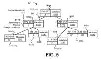
- FIG. 5depicts one embodiment of a forward index
- FIG. 6depicts one embodiment of a reverse index
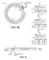
- FIG. 7Adepicts one embodiment of an append point within a physical storage space of a non-volatile storage device
- FIG. 7Bdepicts cyclic, sequential storage operations on a non-volatile storage device
- FIG. 8depicts one embodiment of a log-based data format
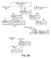
- FIGS. 9A-Edepict exemplary storage metadata comprising a separate inflight index for atomic storage operations
- FIG. 10depicts an incomplete atomic storage operation
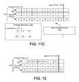
- FIGS. 11A-Cdepict exemplary persistent metadata flags for atomic storage operations
- FIG. 12depicts another exemplary persistent metadata flag for atomic storage operations
- FIGS. 13A-Cdepict exemplary persistent metadata flags for atomic storage operations
- FIG. 14is a flow diagram of one embodiment of a method for providing atomic storage operations on a non-volatile storage device
- FIG. 15is a flow diagram of another embodiment of a method for providing atomic storage operations on a non-volatile storage device
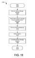
- FIG. 16is a flow diagram of another embodiment of a method for providing atomic storage operations on a non-volatile storage device.
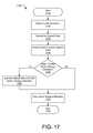
- FIG. 17is a flow diagram of one embodiment of a method for reconstructing storage metadata from an event log of sequential log-based data.
- modulesmay be implemented as a hardware circuit comprising custom VLSI circuits or gate arrays, off-the-shelf semiconductors such as logic chips, transistors, or other discrete components.
- a modulemay also be implemented in programmable hardware devices such as field programmable gate arrays, programmable array logic, programmable logic devices, or the like.
- Modulesmay also be implemented in software for execution by various types of processors.
- An identified module of executable codemay, for instance, comprise one or more physical or logical blocks of computer instructions which may, for instance, be organized as an object, procedure, or function. Nevertheless, the executables of an identified module need not be physically located together, but may comprise disparate instructions stored in different locations which, when joined logically together, comprise the module and achieve the stated purpose for the module.
- a module of executable codemay be a single instruction, or many instructions, and may even be distributed over several different code segments, among different programs, and across several memory devices.
- operational datamay be identified and illustrated herein within modules, and may be embodied in any suitable form and organized within any suitable type of data structure. The operational data may be collected as a single data set, or may be distributed over different locations including over different storage devices, and may exist, at least partially, merely as electronic signals on a system or network.
- the software portionsare stored on one or more computer readable media.
- Reference to a computer readable mediummay take any form capable of storing machine-readable instructions on a digital processing apparatus.
- a computer readable mediummay be embodied by a compact disk, digital-video disk, a magnetic tape, a Bernoulli drive, a magnetic disk, a punch card, flash memory, integrated circuits, or other digital processing apparatus memory device.
- the schematic flow chart diagrams included hereinare generally set forth as logical flow chart diagrams. As such, the depicted order and labeled steps are indicative of one embodiment of the presented method. Other steps and methods may be conceived that are equivalent in function, logic, or effect to one or more steps, or portions thereof, of the illustrated method. Additionally, the format and symbols employed are provided to explain the logical steps of the method and are understood not to limit the scope of the method. Although various arrow types and line types may be employed in the flow chart diagrams, they are understood not to limit the scope of the corresponding method. Indeed, some arrows or other connectors may be used to indicate only the logical flow of the method. For instance, an arrow may indicate a waiting or monitoring period of unspecified duration between enumerated steps of the depicted method. Additionally, the order in which a particular method occurs may or may not strictly adhere to the order of the corresponding steps shown.
- FIG. 1depicts one embodiment of a system 100 for reducing data loss.
- the system 100includes a host computing system 114 , a throughput management apparatus 122 , and a storage device 102 .
- the host computing system 114may be a computer such as a server, laptop, desktop, a mobile device, or other computing device known in the art.
- the host computing system 114typically includes components such as memory, processors, buses, and other components as known to those of skill in the art.
- the host computing system 114stores data in the storage device 102 and communicates data with the storage device 102 via a communications connection.
- the storage device 102may be internal to the host computing system 114 or external to the host computing system 114 .
- the communications connectionmay be a bus, a network, or other manner of connection allowing the transfer of data between the host computing system 114 and the storage device 102 .
- the storage device 102is connected to the host computing system 114 by a PCI connection such as PCI express (“PCI-e”).
- PCI-ePCI express
- the storage device 102may be a card that plugs into a PCI-e connection on the host computing system 114 .
- the storage device 102performs data storage operations such as reads, writes, erases, etc.
- a power connection and the communications connection for the storage device 102are part of the same physical connection between the host computing system 114 and the storage device 102 .
- the storage device 102may receive power over PCI, PCI-e, serial advanced technology attachment (“serial ATA” or “SATA”), parallel ATA (“PATA”), small computer system interface (“SCSI”), IEEE 1394 (“FireWire”), Fiber Channel, universal serial bus (“USB”), PCIe-AS, or another connection with the host computing system 114 .
- the storage device 102provides nonvolatile storage for the host computing system 114 .
- FIG. 1shows the storage device 102 as a nonvolatile non-volatile storage device 102 comprising a storage controller 104 , a write data pipeline 106 , a read data pipeline 108 , and nonvolatile non-volatile storage media 110 .
- the storage device 102may contain additional components that are not shown in order to provide a simpler view of the storage device 102 .
- the non-volatile storage media 110stores data such that the data is retained even when the storage device 102 is not powered.
- the non-volatile storage media 110comprises a solid-state storage media, such as flash memory, nano random access memory (“NRAM”), magneto-resistive RAM (“MRAM”), dynamic RAM (“DRAM”), phase change RAM (“PRAM”), Racetrack memory, Memristor memory, nanocrystal wire-based memory, silicon-oxide based sub-10 nanometer process memory, graphene memory, Silicon-Oxide-Nitride-Oxide-Silicon (“SONOS”), Resistive random-access memory (“RRAM”), programmable metallization cell (“PMC”), conductive-bridging RAM (“CBRAM”), and the like.
- NRAMnano random access memory
- MRAMmagneto-resistive RAM
- DRAMdynamic RAM
- PRAMphase change RAM
- Racetrack memoryMemristor memory
- nanocrystal wire-based memorysilicon-oxide based sub-10 nanometer
- the storage device 102includes non-volatile storage media 110
- the storage device 102may include magnetic media such as hard disks, tape, and the like, optical media, or other nonvolatile data storage media.
- the storage device 102also includes a storage controller 104 that coordinates the storage and retrieval of data in the non-volatile storage media 110 .
- the storage controller 104may use one or more indexes to locate and retrieve data, and perform other operations on data stored in the storage device 102 .
- the storage controller 104may include a groomer for performing data grooming operations such as garbage collection.
- the storage device 102implements a write data pipeline 106 and a read data pipeline 108 , an example of which is described in greater detail below.
- the write data pipeline 106may perform certain operations on data as the data is transferred from the host computing system 114 into the non-volatile storage media 110 . These operations may include, for example, error correction code (ECC) generation, encryption, compression, and others.
- ECCerror correction code
- the read data pipeline 108may perform similar and potentially inverse operations on data that is being read out of non-volatile storage media 110 and sent to the host computing system 114 .
- the host computing system 114includes one or more other components in addition to the storage device 102 , such as additional storage devices, graphics processors, network cards, and the like.
- additional storage devicessuch as additional storage devices, graphics processors, network cards, and the like.
- the componentsmay be internal or external to the host computing system 114 .
- some of the componentsmay be PCI or PCI-e cards that connect to the host computing system 114 and receive power through the host computing system 114 .
- the driver 118is an application program interface (“API”) and acts to translate commands and other data to a form suitable to be sent to a storage controller 104 .
- the driver 118includes one or more functions of the storage controller 104 .
- the driver 118may include all or a portion of the modules described below and may include one or more indexes or maps for the storage devices 106 .
- the driver 118 , one or more storage controllers 104 , and one or more storage devices 106 comprising the storage system 102have a storage interface 116 connection to a file system/file server and allocation traditionally done in a file system/file server is advantageously pushed down (i.e., offloaded) to the storage system 102 .
- a logical identifieris an identifier of a data unit that differs from a physical address where data of the data unit is stored.
- a data unitis any set of data that is logically grouped together.
- a data unitmay be a file, an object, a data segment of a redundant array of inexpensive/independent disks/drives (“RAID”) data stripe, or other data set used in data storage.
- the data unitmay be executable code, data, metadata, directories, indexes, any other type of data that may be stored in a memory device, or a combination thereof.
- the data unitmay be identified by a name, by a logical address, a physical address, an address range, or other convention for identifying data units.
- a logical identifierincludes data unit identifiers, such as a file name, an object identifier, an Mode, Universally Unique Identifier (“UUID”), Globally Unique Identifier (“GUID”), or other data unit label, and may also include a logical block address (“LBA”), cylinder/head/sector (“CHS”), or other lower level logical identifier.
- a logical identifiergenerally includes any logical label that can be mapped to a physical location.
- the storage device 106stores data in a sequential log-based format on the non-volatile storage media 110 .
- data of the data unitis read from one physical storage location, modified, and then written to a different physical storage location.
- the order and sequence of writing data to the data storage device 106may comprise an event log of the sequence of storage operations performed on the non-volatile storage device 102 . By traversing the event log (and/or replaying the sequence of storage operations), and storage metadata, such as a forward index can be constructed or reconstructed.
- logical identifiersIn a typical random access device, logical identifiers have almost a one-to-one correspondence to physical addresses of the random access device. This one-to-one mapping in a typical random access device (excluding a small number of physical addresses on the random access device reserved for bad block mapping) also correlates to a near one-to-one relationship between storage capacity associated with logical identifiers and physical capacity associated with physical addresses. For example, if a logical identifier is a logical block address (“LBA”), each logical block associated with an LBA has a fixed size. A corresponding physical block on the random access device is typically the same size as a logical block.
- LBAlogical block address
- LBAlogical identifiers
- This continuity of LBA to PBA mappingis generally depended upon and utilized by file systems to defragment the data stored on the data storage device. Similarly, some systems may use this continuity to locate the data on specific physical tracks to improve performance as is the case of a technique called “short stroking” the disk drive.
- the highly predictable LBA to PBA mappingis essential in certain applications to indirectly manage the storage of the data in the physical storage space through direct management of the logical address space.
- the storage system 102may be a log structured file system such that there is no “fixed” relationship or algorithm to determine the mapping of the LBA to the PBA, or in another embodiment, may be random access, but may be accessed by more than one client 110 or file server 114 /file system such that the logical identifiers allocated to each client 110 or file server 114 /file system represent a storage capacity much larger than the one-to-one relationship of logical to physical identifiers of typical systems.
- the storage system 102may also be thinly provisioned such that one or more clients 110 each has an allocated logical address range that is much larger than the storage capacity of the storage devices 106 in the storage system 102 .
- the storage system 102manages and allocates logical identifiers such that there is no pre-determined one-to-one or near one-to-one relationship between logical identifiers and physical identifiers.
- the system 100is advantageous because it allows more efficient management of storage capacity than typical storage systems. For example, for typical random access devices accessible by a number of clients 110 , if each client is allocated a certain amount storage space, the storage space typically will exist and be tied up in the allocations even if the actual amount of storage space occupied is much less.
- the system 100is also advantageous because the system 100 reduces complexity of standard thin provisioning systems connected to storage devices 106 .
- a standard thin provisioning systemhas a thin provisioning layer comprising a logical-to-logical mapping between logical identifiers in the logical address space and physical storage locations. The system 100 is more efficient because multiple layers of mapping are eliminated and thin provisioning (logical-to-physical mapping) is done at the lowest level.
- FIG. 2is a schematic block diagram illustrating one embodiment 200 of a non-volatile storage device controller 202 that includes a write data pipeline 106 and a read data pipeline 108 in a non-volatile storage device 102 in accordance with the present invention.
- the non-volatile storage device controller 202may include a number of storage controllers 0 -N 104 a - n , each controlling non-volatile storage media 110 . In the depicted embodiment, two non-volatile controllers are shown: non-volatile controller 0 104 a and storage controller N 104 n , and each controlling respective non-volatile storage media 110 a - n .
- storage controller 0 104 acontrols a data channel so that the attached non-volatile storage media 110 a stores data.
- Storage controller N 104 ncontrols an index metadata channel associated with the stored data and the associated non-volatile storage media 110 n stores index metadata.
- the non-volatile storage device controller 202includes a single non-volatile controller 104 a with a single non-volatile storage media 110 a .
- one or more non-volatile controllers 104 a - 104 n - 1coupled to their associated non-volatile storage media 110 a - 110 n - 1 , control data while at least one storage controller 104 n , coupled to its associated non-volatile storage media 110 n , controls index metadata.
- At least one non-volatile controller 104is a field-programmable gate array (“FPGA”) and controller functions are programmed into the FPGA.
- the FPGAis a Xilinx® FPGA.
- the storage controller 104comprises components specifically designed as a storage controller 104 , such as an application-specific integrated circuit (“ASIC”) or custom logic solution.
- ASICapplication-specific integrated circuit
- Each storage controller 104typically includes a write data pipeline 106 and a read data pipeline 108 , which are describe further in relation to FIG. 3 .
- at least one storage controller 104is made up of a combination FPGA, ASIC, and custom logic components.
- the non-volatile storage media 110is an array of non-volatile storage elements 216 , 218 , 220 , arranged in banks 214 , and accessed in parallel through a bi-directional storage input/output (“I/O”) bus 210 .
- the storage I/O bus 210in one embodiment, is capable of unidirectional communication at any one time. For example, when data is being written to the non-volatile storage media 110 , data cannot be read from the non-volatile storage media 110 . In another embodiment, data can flow both directions simultaneously.
- bi-directionalrefers to a data pathway that can have data flowing in only one direction at a time, but when data flowing one direction on the bi-directional data bus is stopped, data can flow in the opposite direction on the bi-directional data bus.
- a non-volatile storage element(e.g., SSS 0 . 0 216 a ) is typically configured as a chip (a package of one or more dies) or a die on a circuit board.
- a non-volatile storage element(e.g., 216 a ) operates independently or semi-independently of other non-volatile storage elements (e.g., 218 a ) even if these several elements are packaged together in a chip package, a stack of chip packages, or some other package element.
- a row of non-volatile storage elements 216 a , 216 b , 216 mis designated as a bank 214 .
- nthere may be “n” banks 214 a - n and “m” non-volatile storage elements 216 a - m , 218 a - m , 220 a - m per bank in an array of n ⁇ m non-volatile storage elements 216 , 218 , 220 in a non-volatile storage media 110 .
- a non-volatile storage media 110 aincludes twenty non-volatile storage elements 216 a - 216 m per bank 214 with eight banks 214 .
- the non-volatile storage media 110 aincludes twenty-four non-volatile storage elements 216 a - 216 m per bank 214 with eight banks 214 .
- one or more additional columns (P)may also be addressed and operated in parallel with other non-volatile storage elements 216 a , 216 b , 216 m for one or more rows.
- the added P columnsin one embodiment, store parity data for the portions of an ECC chunk (i.e., an ECC codeword) that span m storage elements for a particular bank.
- each non-volatile storage element 216 , 218 , 220is comprised of single-level cell (“SLC”) devices. In another embodiment, each non-volatile storage element 216 , 218 , 220 is comprised of multi-level cell (“MLC”) devices.
- SLCsingle-level cell
- MLCmulti-level cell
- non-volatile storage elements that share a common line 211 on the storage I/O bus 210 aare packaged together.
- a non-volatile storage element 216 , 218 , 220may have one or more dies per package with one or more packages stacked vertically and each die may be accessed independently.
- a non-volatile storage elemente.g., SSS 0 . 0 216 a
- SSS 0 . 0 216 amay have one or more virtual dies per die and one or more dies per package and one or more packages stacked vertically and each virtual die may be accessed independently.
- a non-volatile storage element SSS 0 . 0 216 amay have one or more virtual dies per die and one or more dies per package with some or all of the one or more dies stacked vertically and each virtual die may be accessed independently.
- two diesare stacked vertically with four stacks per group to form eight storage elements (e.g., SSS 0 . 0 -SSS 8 . 0 ) 216 a , 218 a . . . 220 a , each in a separate bank 214 a , 214 b . . . 214 n .
- 24 storage elementse.g., SSS 0 . 0 -SSS 0 . 24
- 216 a , 216 b , . . . 216 mform a logical bank 214 a so that each of the eight logical banks has 24 storage elements (e.g., SSS 0 .
- Datais sent to the non-volatile storage media 110 over the storage I/O bus 210 to all storage elements of a particular group of storage elements (SSS 0 . 0 -SSS 8 . 0 ) 216 a , 218 a , 220 a .
- the storage control bus 212 ais used to select a particular bank (e.g., Bank 0 214 a ) so that the data received over the storage I/O bus 210 connected to all banks 214 is written just to the selected bank 214 a.
- the storage I/O bus 210is comprised of one or more independent I/O buses (“IIOBa-m” comprising 210 a.a - m . . . 210 n.a - m ) wherein the non-volatile storage elements within each column share one of the independent I/O buses that are connected to each non-volatile storage element 216 , 218 , 220 in parallel.
- IIOBa-mindependent I/O buses
- a second independent I/O bus 210 a.b of the storage I/O bus 210 bmay be physically connected to a second non-volatile storage element 216 b , 218 b , 220 b of each bank 214 a - n .
- Each non-volatile storage element 216 a , 216 b , 216 m in a bank 214 a(a row of non-volatile storage elements as illustrated in FIG. 2 ) may be accessed simultaneously and/or in parallel.
- non-volatile storage elements 216 , 218 , 220comprise stacked packages of dies, all packages in a particular stack are physically connected to the same independent I/O bus.
- Simultaneouslyalso includes near simultaneous access where devices are accessed at slightly different intervals to avoid switching noise. Simultaneously is used in this context to be distinguished from a sequential or serial access wherein commands and/or data are sent individually one after the other.
- banks 214 a - nare independently selected using the storage control bus 212 .
- a bank 214is selected using a chip enable or chip select. Where both chip select and chip enable are available, the storage control bus 212 may select one package within a stack of packages. In other embodiments, other commands are used by the storage control bus 212 to individually select one package within a stack of packages.
- Non-volatile storage elements 216 , 218 , 220may also be selected through a combination of control signals and address information transmitted on storage I/O bus 210 and the storage control bus 212 .
- each non-volatile storage element 216 , 218 , 220is partitioned into erase blocks and each erase block is partitioned into pages.
- An erase block on a non-volatile storage element 216 , 218 220may be called a physical erase block or “PEB.”
- a typical pageis 2048 bytes (“2 kB”).
- a non-volatile storage elemente.g., SSS 0 . 0
- SSS 0 . 0includes two registers and can program two pages so that a two-register non-volatile storage element 216 , 218 , 220 has a capacity of 4 kB.
- a bank 214 of 20 non-volatile storage elements 216 a , 216 b , 216 mwould then have an 80 kB capacity of pages accessed with the same address going out the independent I/O buses of the storage I/O bus 210 .
- This group of pages in a bank 214 of non-volatile storage elements 216 a , 216 b , . . . 216 m of 80 kBmay be called a logical page or virtual page.
- an erase block of each storage element 216 a , 216 b , . . . 216 m of a bank 214 amay be grouped to form a logical erase block (which may also be called a virtual erase block).
- an erase block of pages within a non-volatile storage elementis erased when an erase command is received within the non-volatile storage element.
- a physical addressis sent on the storage I/O bus 210 and is followed by the packet.
- the physical addresscontains enough information for the non-volatile storage element 216 to direct the packet to the designated location within the page. Since all storage elements in a column of storage elements (e.g., SSS 0 . 0 -SSS N. 0 216 a , 218 a , . . .
- the bank 214 athat includes the non-volatile storage element SSS 0 . 0 216 a with the correct page where the data packet is to be written is selected by the storage control bus 212 a and other banks 214 b . . . 214 n of the non-volatile storage 110 a are deselected.
- a read command on the storage I/O bus 210requires a signal on the storage control bus 212 to select a single bank 214 a and the appropriate page within that bank 214 a .
- a read commandreads an entire page, and because there are multiple non-volatile storage elements 216 a , 216 b , . . . 216 m in parallel in a bank 214 a , an entire logical page is read with a read command. However, the read command may be broken into subcommands, as will be explained below with respect to bank interleave. Similarly, an entire logical page may be written to the non-volatile storage elements 216 a , 216 b , . . . 216 m of a bank 214 a in a write operation.
- An erase block erase commandmay be sent out to erase an erase block over the storage I/O bus 210 with a particular erase block address to erase a particular erase block.
- storage controller 104 amay send an erase block erase command over the parallel paths (independent I/O buses 210 a - n.a - m ) of the storage I/O bus 210 to erase a logical erase block, each with a particular erase block address to erase a particular erase block.
- a particular banke.g., Bank 0 214 a
- no particular banke.g., Bank 0 214 a
- the storage control bus 212or all of the banks are selected to enable erasure of similarly addressed erase blocks in all of the banks (Banks 1 -N 214 b - n ) in parallel.
- Other commandsmay also be sent to a particular location using a combination of the storage I/O bus 210 and the storage control bus 212 .
- One of skill in the artwill recognize other ways to select a particular storage location using the bi-directional storage I/O bus 210 and the storage control bus 212 .
- packetsare written sequentially to the non-volatile storage media 110 .
- storage controller 104 astreams packets to storage write buffers of a bank 214 a of storage elements 216 and, when the buffers are full, the packets are programmed to a designated logical page.
- Storage controller 104 athen refills the storage write buffers with packets and, when full, the packets are written to the next logical page.
- the next logical pagemay be in the same bank 214 a or another bank (e.g., 214 b ).
- This processcontinues, logical page after logical page, typically until a logical erase block is filled.
- the streamingmay continue across logical erase block boundaries with the process continuing, logical erase block after logical erase block.
- a read, modify, write operationdata packets associated with requested data are located and read in a read operation.
- Data segments of the modified requested data that have been modifiedare not written to the location from which they are read. Instead, the modified data segments are again converted to data packets and then written sequentially to the next available location in the logical page currently being written.
- the index entries for the respective data packetsare modified to point to the packets that contain the modified data segments.
- the entry or entries in the index for data packets associated with the same requested data that have not been modifiedwill include pointers to original location of the unmodified data packets.
- the original requested datais maintained, for example to maintain a previous version of the requested data, the original requested data will have pointers in the index to all data packets as originally written.
- the new requested datawill have pointers in the index to some of the original data packets and pointers to the modified data packets in the logical page that is currently being written.
- the indexincludes an entry for the original requested data mapped to a number of packets stored in the non-volatile storage media 110 .
- a new copy of the requested datais created and a new entry is created in the index mapping the new copy of the requested data to the original packets.
- the new copy of the requested datais also written to the non-volatile storage media 110 with its location mapped to the new entry in the index.
- the new copy of the requested data packetsmay be used to identify the packets within the original requested data that are referenced in case changes have been made in the original requested data that have not been propagated to the copy of the requested data and the index is lost or corrupted.
- sequentially writing packetsfacilitates a more even use of the non-volatile storage media 110 and allows the solid-storage device controller 202 to monitor storage hot spots and level usage of the various logical pages in the non-volatile storage media 110 .
- Sequentially writing packetsalso facilitates a powerful, efficient garbage collection system, which is described in detail below.
- One of skill in the artwill recognize other benefits of sequential storage of data packets.
- the non-volatile storage device controller 202also includes a data bus 204 , a local bus 206 , a buffer controller 208 , buffers 0 -N 222 a - n , a master controller 224 , a direct memory access (“DMA”) controller 226 , a memory controller 228 , a dynamic memory array 230 , a static random memory array 232 , a management controller 234 , a management bus 236 , a bridge 238 to a system bus 240 , and miscellaneous logic 242 , which are described below.
- DMAdirect memory access
- the system bus 240is coupled to one or more network interface cards (“NICs”) 244 , some of which may include remote DMA (“RDMA”) controllers 246 , one or more central processing unit (“CPU”) 248 , one or more external memory controllers 250 and associated external memory arrays 252 , one or more storage controllers 254 , peer controllers 256 , and application specific processors 258 , which are described below.
- NICsnetwork interface cards
- RDMAremote DMA
- CPUcentral processing unit
- external memory controllers 250 and associated external memory arrays 252one or more storage controllers 254
- peer controllers 256peer controllers 256
- application specific processors 258application specific processors
- the storage controller(s) 104communicate data to the non-volatile storage media 110 over a storage I/O bus 210 .
- the storage I/O bus 210is an array of busses, one for each column of storage elements 216 , 218 , 220 spanning the banks 214 .
- the term “storage I/O bus”may refer to one storage I/O bus 210 or an array of independent data busses wherein individual data busses of the array independently communicate different data relative to one another.
- each storage I/O bus 210 accessing a column of storage elementsmay include a logical-to-physical mapping for storage divisions (e.g., erase blocks) accessed in a column of storage elements 216 a , 218 a , 220 a .
- This mapping(or bad block remapping) allows a logical address mapped to a physical address of a storage division to be remapped to a different storage division if the first storage division fails, partially fails, is inaccessible, or has some other problem.
- Datamay also be communicated to the storage controller(s) 104 from a requesting device 155 through the system bus 240 , bridge 238 , local bus 206 , buffer(s) 222 , and finally over a data bus 204 .
- the data bus 204typically is connected to one or more buffers 222 a - n controlled with a buffer controller 208 .
- the buffer controller 208typically controls transfer of data from the local bus 206 to the buffers 222 and through the data bus 204 to the pipeline input buffer 306 and output buffer 330 .
- the buffer controller 208typically controls how data arriving from a requesting device can be temporarily stored in a buffer 222 and then transferred onto a data bus 204 , or vice versa, to account for different clock domains, to prevent data collisions, etc.
- the buffer controller 208typically works in conjunction with the master controller 224 to coordinate data flow. As data arrives, the data will arrive on the system bus 240 , be transferred to the local bus 206 through a bridge 238 .
- the datais transferred from the local bus 206 to one or more data buffers 222 as directed by the master controller 224 and the buffer controller 208 .
- the datathen flows out of the buffer(s) 222 to the data bus 204 , through a non-volatile controller 104 , and on to the non-volatile storage media 110 such as NAND flash or other storage media.
- data and associated out-of-band metadata (“metadata”) arriving with the datais communicated using one or more data channels comprising one or more storage controllers 104 a - 104 n - 1 and associated non-volatile storage media 110 a - 110 n - 1 while at least one channel (storage controller 104 n , non-volatile storage media 110 n ) is dedicated to in-band metadata, such as index information and other metadata generated internally to the non-volatile storage device 102 .
- the local bus 206is typically a bidirectional bus or set of busses that allows for communication of data and commands between devices internal to the non-volatile storage device controller 202 and between devices internal to the non-volatile storage device 102 and devices 244 - 258 connected to the system bus 240 .
- the bridge 238facilitates communication between the local bus 206 and system bus 240 .
- One of skill in the artwill recognize other embodiments such as ring structures or switched star configurations and functions of buses 240 , 206 , 204 , 210 and bridges 238 .
- the system bus 240is typically a bus of a host computing system 114 or other device in which the non-volatile storage device 102 is installed or connected.
- the system bus 240may be a PCI-e bus, a Serial Advanced Technology Attachment (“serial ATA”) bus, parallel ATA, or the like.
- the system bus 240is an external bus such as small computer system interface (“SCSI”), FireWire, Fiber Channel, USB, PCIe-AS, or the like.
- SCSIsmall computer system interface
- FireWireFireWire
- Fiber ChannelUSB
- PCIe-ASPCIe-AS
- the non-volatile storage device 102may be packaged to fit internally to a device or as an externally connected device.
- the non-volatile storage device controller 202includes a master controller 224 that controls higher-level functions within the non-volatile storage device 102 .
- the master controller 224controls data flow by interpreting object requests and other requests, directs creation of indexes to map object identifiers associated with data to physical locations of associated data, coordinating DMA requests, etc. Many of the functions described herein are controlled wholly or in part by the master controller 224 .
- the master controller 224uses embedded controller(s). In another embodiment, the master controller 224 uses local memory such as a dynamic memory array 230 (dynamic random access memory “DRAM”), a static memory array 232 (static random access memory “SRAM”), etc. In one embodiment, the local memory is controlled using the master controller 224 . In another embodiment, the master controller 224 accesses the local memory via a memory controller 228 . In another embodiment, the master controller 224 runs a Linux server and may support various common server interfaces, such as the World Wide Web, hyper-text markup language (“HTML”), etc. In another embodiment, the master controller 224 uses a nano-processor. The master controller 224 may be constructed using programmable or standard logic, or any combination of controller types listed above. One skilled in the art will recognize many embodiments for the master controller 224 .
- DRAMdynamic random access memory
- SRAMstatic memory array
- the local memoryis controlled using the master controller 224 .
- the master controller 224accesses the local memory via a memory controller 2
- the master controller 224divides the work load among internal controllers, such as the storage controllers 104 a - n .
- the master controller 224may divide an object to be written to the data storage devices (e.g., non-volatile storage media 110 a - n ) so that a portion of the object is stored on each of the attached data storage devices. This feature is a performance enhancement allowing quicker storage and access to an object.
- the master controller 224is implemented using an FPGA.
- the firmware within the master controller 224may be updated through the management bus 236 , the system bus 240 over a network connected to a NIC 244 or other device connected to the system bus 240 .
- the master controller 224which manages objects, emulates block storage such that a host computing system 114 or other device connected to the storage device/non-volatile storage device 102 views the storage device/non-volatile storage device 102 as a block storage device and sends data to specific physical addresses in the storage device/non-volatile storage device 102 .
- the master controller 224then divides up the blocks and stores the data blocks as it would objects.
- the master controller 224maps the blocks and physical address sent with the block to the actual locations determined by the master controller 224 . The mapping is stored in the object index.
- a block device application program interface(“API”) is provided in a driver in a computer such as the host computing system 114 , or other device wishing to use the storage device/non-volatile storage device 102 as a block storage device.
- APIapplication program interface
- the master controller 224coordinates with NIC controllers 244 and embedded RDMA controllers 246 to deliver just-in-time RDMA transfers of data and command sets.
- NIC controller 244may be hidden behind a non-transparent port to enable the use of custom drivers.
- a driver on a host computing system 114may have access to the computer network 116 through an I/O memory driver using a standard stack API and operating in conjunction with NICs 244 .
- the master controller 224is also a redundant array of independent drive (“RAID”) controller. Where the data storage device/non-volatile storage device 102 is networked with one or more other data storage devices/non-volatile storage devices 102 , the master controller 224 may be a RAID controller for single tier RAID, multi-tier RAID, progressive RAID, etc. The master controller 224 also allows some objects to be stored in a RAID array and other objects to be stored without RAID. In another embodiment, the master controller 224 may be a distributed RAID controller element. In another embodiment, the master controller 224 may comprise many RAID, distributed RAID, and other functions as described elsewhere.
- RAIDredundant array of independent drive
- the master controller 224controls storage of data in a RAID-like structure where parity information is stored in one or more storage elements 216 , 218 , 220 of a logical page where the parity information protects data stored in the other storage elements 216 , 218 , 220 of the same logical page.
- the master controller 224coordinates with single or redundant network managers (e.g., switches) to establish routing, to balance bandwidth utilization, failover, etc.
- the master controller 224coordinates with integrated application specific logic (via local bus 206 ) and associated driver software.
- the master controller 224coordinates with attached application specific processors 258 or logic (via the external system bus 240 ) and associated driver software.
- the master controller 224coordinates with remote application specific logic (via the computer network 116 ) and associated driver software.
- the master controller 224coordinates with the local bus 206 or external bus attached hard disk drive (“HDD”) storage controller.
- HDDhard disk drive
- the master controller 224communicates with one or more storage controllers 254 where the storage device/non-volatile storage device 102 may appear as a storage device connected through a SCSI bus, Internet SCSI (“iSCSI”), fiber channel, etc. Meanwhile the storage device/non-volatile storage device 102 may autonomously manage objects and may appear as an object file system or distributed object file system.
- the master controller 224may also be accessed by peer controllers 256 and/or application specific processors 258 .
- the master controller 224coordinates with an autonomous integrated management controller to periodically validate FPGA code and/or controller software, validate FPGA code while running (reset) and/or validate controller software during power on (reset), support external reset requests, support reset requests due to watchdog timeouts, and support voltage, current, power, temperature, and other environmental measurements and setting of threshold interrupts.
- the master controller 224manages garbage collection to free erase blocks for reuse.
- the master controller 224manages wear leveling.
- the master controller 224allows the data storage device/non-volatile storage device 102 to be partitioned into multiple logical devices and allows partition-based media encryption.
- the master controller 224supports a storage controller 104 with advanced, multi-bit ECC correction.
- a master controller 224in a storage controller 202 , or more specifically in a non-volatile storage device 102 .
- the non-volatile storage device controller 202includes a memory controller 228 , which controls a dynamic random memory array 230 and/or a static random memory array 232 .
- the memory controller 228may be independent or integrated with the master controller 224 .
- the memory controller 228typically controls volatile memory of some type, such as DRAM (dynamic random memory array 230 ) and SRAM (static random memory array 232 ).
- the memory controller 228also controls other memory types such as electrically erasable programmable read only memory (“EEPROM”), etc.
- EEPROMelectrically erasable programmable read only memory
- the memory controller 228controls two or more memory types and the memory controller 228 may include more than one controller.
- the memory controller 228controls as much SRAM 232 as is feasible and by DRAM 230 to supplement the SRAM 232 .
- the object indexis stored in memory 230 , 232 and then periodically offloaded to a channel of the non-volatile storage media 110 n or other non-volatile memory.
- the memory controller 228dynamic memory array 230
- static memory array 232static memory array
- the non-volatile storage device controller 202includes a DMA controller 226 that controls DMA operations between the storage device/non-volatile storage device 102 and one or more external memory controllers 250 and associated external memory arrays 252 and CPUs 248 .
- the external memory controllers 250 and external memory arrays 252are called external because they are external to the storage device/non-volatile storage device 102 .
- the DMA controller 226may also control RDMA operations with requesting devices through a NIC 244 and associated RDMA controller 246 .
- the non-volatile storage device controller 202includes a management controller 234 connected to a management bus 236 .
- the management controller 234manages environmental metrics and status of the storage device/non-volatile storage device 102 .
- the management controller 234may monitor device temperature, fan speed, power supply settings, etc. over the management bus 236 .
- the management controller 234may support the reading and programming of erasable programmable read only memory (“EEPROM”) for storage of FPGA code and controller software.
- EEPROMerasable programmable read only memory
- the management bus 236is connected to the various components within the storage device/non-volatile storage device 102 .
- the management controller 234may communicate alerts, interrupts, etc.
- the management bus 236is an Inter-Integrated Circuit (“I2C”) bus.
- I2CInter-Integrated Circuit
- the non-volatile storage device controller 202includes miscellaneous logic 242 that may be customized for a specific application.
- miscellaneous logic 242may be customized for a specific application.
- custom logicmay be included based on a particular application, customer requirement, storage requirement, etc.
- FIG. 3is a schematic block diagram illustrating one embodiment 300 of a storage controller 104 with a write data pipeline 106 , a read data pipeline 108 and a throughput management apparatus 122 in a non-volatile storage device 102 in accordance with the present invention.
- the embodiment 300includes a data bus 204 , a local bus 206 , and buffer control 208 , which are substantially similar to those described in relation to the non-volatile storage device controller 202 of FIG. 2 .
- the write data pipeline 106includes a packetizer 302 and an error-correcting code (“ECC”) generator 304 .
- ECCerror-correcting code
- the write data pipeline 106includes an input buffer 306 , a write synchronization buffer 308 , a write program module 310 , a compression module 312 , an encryption module 314 , a garbage collector bypass 316 (with a portion within the read data pipeline 108 ), a media encryption module 318 , and a write buffer 320 .
- the read data pipeline 108includes a read synchronization buffer 328 , an ECC correction module 322 , a depacketizer 324 , an alignment module 326 , and an output buffer 330 .
- the read data pipeline 108may include a media decryption module 332 , a portion of the garbage collector bypass 316 , a decryption module 334 , a decompression module 336 , and a read program module 338 .
- the storage controller 104may also include control and status registers 340 and control queues 342 , a bank interleave controller 344 , a synchronization buffer 346 , a storage bus controller 348 , and a multiplexer (“MUX”) 350 .
- MUXmultiplexer
- the write data pipeline 106includes a packetizer 302 that receives a data or metadata segment to be written to the non-volatile storage, either directly or indirectly through another write data pipeline 106 stage, and creates one or more packets sized for the non-volatile storage media 110 .
- the data or metadata segmentis typically part of a data structure such as an object, but may also include an entire data structure. In another embodiment, the data segment is part of a block of data, but may also include an entire block of data.
- a set of datasuch as a data structure is received from a computer such as the host computing system 114 , or other computer or device and is transmitted to the non-volatile storage device 102 in data segments streamed to the non-volatile storage device 102 .
- a data segmentmay also be known by another name, such as data parcel, but as referenced herein includes all or a portion of a data structure or data block.
- Each data structureis stored as one or more packets.
- Each data structuremay have one or more container packets.
- Each packetcontains a header.
- the headermay include a header type field. Type fields may include data, attribute, metadata, data segment delimiters (multi-packet), data structures, data linkages, and the like.
- the headermay also include information regarding the size of the packet, such as the number of bytes of data included in the packet. The length of the packet may be established by the packet type.
- the headermay include information that establishes the relationship of the packet to a data structure. An example might be the use of an offset in a data packet header to identify the location of the data segment within the data structure.
- One of skill in the artwill recognize other information that may be included in a header added to data by a packetizer 302 and other information that may be added to a data packet.
- Each packetincludes a header and possibly data from the data or metadata segment.
- the header of each packetincludes pertinent information to relate the packet to the data structure to which the packet belongs.
- the headermay include an object identifier or other data structure identifier and offset that indicate the data segment, object, data structure or data block from which the data packet was formed.
- the headermay also include a logical address used by the storage bus controller 348 to store the packet.
- the headermay also include information regarding the size of the packet, such as the number of bytes included in the packet.
- the headermay also include a sequence number that identifies where the data segment belongs with respect to other packets within the data structure when reconstructing the data segment or data structure.
- the headermay include a header type field.
- Type fieldsmay include data, data structure attributes, metadata, data segment delimiters (multi-packet), data structure types, data structure linkages, and the like.
- data segment delimitersmulti-packet
- data structure typesdata structure linkages, and the like.
- packetizer 302One of skill in the art will recognize other information that may be included in a header added to data or metadata by a packetizer 302 and other information that may be added to a packet.
- the write data pipeline 106includes an ECC generator 304 that that generates one or more error-correcting codes (“ECC”) for the one or more packets received from the packetizer 302 .
- ECCerror-correcting codes
- the ECC generator 304typically uses an error-correcting algorithm to generate ECC check bits, which are stored with the one or more data packets.
- the ECC codes generated by the ECC generator 304 together with the one or more data packets associated with the ECC codescomprise an ECC chunk.
- the ECC data stored with the one or more data packetsis used to detect and to correct errors introduced into the data through transmission and storage.
- packetsare streamed into the ECC generator 304 as un-encoded blocks of length N.
- a syndrome of length Sis calculated, appended, and output as an encoded block of length N+S.
- the value of N and Sare dependent upon the characteristics of the ECC algorithm, which is selected to achieve specific performance, efficiency, and robustness metrics.
- ECC algorithmsare not dynamically modified.
- the ECC data stored with the data packetsis robust enough to correct errors in more than two bits.
- the non-volatile storage media 110can be extended. For example, if flash memory is used as the storage medium in the non-volatile storage media 110 , the flash memory may be written approximately 100,000 times without error per erase cycle. This usage limit may be extended using a robust ECC algorithm. Having the ECC generator 304 and corresponding ECC correction module 322 onboard the non-volatile storage device 102 , the non-volatile storage device 102 can internally correct errors and has a longer useful life than if a less robust ECC algorithm is used, such as single bit correction.
- the ECC generator 304may use a less robust algorithm and may correct single-bit or double-bit errors.
- the non-volatile storage device 110may comprise less reliable storage such as multi-level cell (“MLC”) flash in order to increase capacity, which storage may not be sufficiently reliable without more robust ECC algorithms.
- MLCmulti-level cell
- the write pipeline 106includes an input buffer 306 that receives a data segment to be written to the non-volatile storage media 110 and stores the incoming data segments until the next stage of the write data pipeline 106 , such as the packetizer 302 (or other stage for a more complex write data pipeline 106 ) is ready to process the next data segment.
- the input buffer 306typically allows for discrepancies between the rate data segments are received and processed by the write data pipeline 106 using an appropriately sized data buffer.
- the input buffer 306also allows the data bus 204 to transfer data to the write data pipeline 106 at rates greater than can be sustained by the write data pipeline 106 in order to improve efficiency of operation of the data bus 204 .
- a buffering functionis performed elsewhere, such as in the non-volatile storage device 102 but outside the write data pipeline 106 , in the host computing system 114 , such as within a network interface card (“NIC”), or at another device, for example when using remote direct memory access (“RDMA”).
- NICnetwork interface card
- RDMAremote direct memory access
- the write data pipeline 106also includes a write synchronization buffer 308 that buffers packets received from the ECC generator 304 prior to writing the packets to the non-volatile storage media 110 .
- the write synchronization buffer 308is located at a boundary between a local clock domain and a non-volatile storage clock domain and provides buffering to account for the clock domain differences.
- synchronous non-volatile storage media 110may be used and synchronization buffers 308 328 may be eliminated.
- the write data pipeline 106also includes a media encryption module 318 that receives the one or more packets from the packetizer 302 , either directly or indirectly, and encrypts the one or more packets using an encryption key unique to the non-volatile storage device 102 prior to sending the packets to the ECC generator 304 .
- the entire packetis encrypted, including the headers.
- headersare not encrypted.
- encryption keyis understood to mean a secret encryption key that is managed externally from a storage controller 104 .
- the media encryption module 318 and corresponding media decryption module 332provide a level of security for data stored in the non-volatile storage media 110 .
- datais encrypted with the media encryption module 318
- the non-volatile storage media 110is connected to a different storage controller 104 , non-volatile storage device 102 , or server, the contents of the non-volatile storage media 110 typically could not be read without use of the same encryption key used during the write of the data to the non-volatile storage media 110 without significant effort.
- the non-volatile storage device 102does not store the encryption key in non-volatile storage and allows no external access to the encryption key.
- the encryption keyis provided to the storage controller 104 during initialization.
- the non-volatile storage device 102may use and store a non-secret cryptographic nonce that is used in conjunction with an encryption key. A different nonce may be stored with every packet. Data segments may be split between multiple packets with unique nonces for the purpose of improving protection by the encryption algorithm.
- the encryption keymay be received from a host computing system 114 , a server, key manager, or other device that manages the encryption key to be used by the storage controller 104 .
- the non-volatile storage media 110may have two or more partitions and the storage controller 104 behaves as though it was two or more storage controllers 104 , each operating on a single partition within the non-volatile storage media 110 .
- a unique media encryption keymay be used with each partition.
- the write data pipeline 106also includes an encryption module 314 that encrypts a data or metadata segment received from the input buffer 306 , either directly or indirectly, prior sending the data segment to the packetizer 302 , the data segment encrypted using an encryption key received in conjunction with the data segment.
- the encryption keys used by the encryption module 314 to encrypt datamay not be common to all data stored within the non-volatile storage device 102 but may vary on an per data structure basis and received in conjunction with receiving data segments as described below. For example, an encryption key for a data segment to be encrypted by the encryption module 314 may be received with the data segment or may be received as part of a command to write a data structure to which the data segment belongs.
- the solid-state storage device 102may use and store a non-secret cryptographic nonce in each data structure packet that is used in conjunction with the encryption key.
- a different noncemay be stored with every packet.
- Data segmentsmay be split between multiple packets with unique nonces for the purpose of improving protection by the encryption algorithm.
- the encryption keymay be received from a host computing system 114 , another computer, key manager, or other device that holds the encryption key to be used to encrypt the data segment.
- encryption keysare transferred to the storage controller 104 from one of a non-volatile storage device 102 , host computing system 114 , computer, or other external agent, which has the ability to execute industry standard methods to securely transfer and protect private and public keys.
- the encryption module 314encrypts a first packet with a first encryption key received in conjunction with the packet and encrypts a second packet with a second encryption key received in conjunction with the second packet. In another embodiment, the encryption module 314 encrypts a first packet with a first encryption key received in conjunction with the packet and passes a second data packet on to the next stage without encryption.
- the encryption module 314 included in the write data pipeline 106 of the non-volatile storage device 102allows data structure-by-data structure or segment-by-segment data encryption without a single file system or other external system to keep track of the different encryption keys used to store corresponding data structures or data segments.
- Each requesting device 155 or related key managerindependently manages encryption keys used to encrypt only the data structures or data segments sent by the requesting device 155 .
- the encryption module 314may encrypt the one or more packets using an encryption key unique to the non-volatile storage device 102 .
- the encryption module 314may perform this media encryption independently, or in addition to the encryption described above.
- the entire packetis encrypted, including the headers.
- headersare not encrypted.
- the media encryption by the encryption module 314provides a level of security for data stored in the non-volatile storage media 110 .
- non-volatile storage media 110is connected to a different storage controller 104 , non-volatile storage device 102 , or host computing system 114 , the contents of the non-volatile storage media 110 typically could not be read without use of the same encryption key used during the write of the data to the non-volatile storage media 110 without significant effort.
- the write data pipeline 106includes a compression module 312 that compresses the data for metadata segment prior to sending the data segment to the packetizer 302 .
- the compression module 312typically compresses a data or metadata segment using a compression routine known to those of skill in the art to reduce the storage size of the segment. For example, if a data segment includes a string of 512 zeros, the compression module 312 may replace the 512 zeros with code or token indicating the 512 zeros where the code is much more compact than the space taken by the 512 zeros.
- the compression module 312compresses a first segment with a first compression routine and passes along a second segment without compression. In another embodiment, the compression module 312 compresses a first segment with a first compression routine and compresses the second segment with a second compression routine. Having this flexibility within the non-volatile storage device 102 is beneficial so that computing systems 114 or other devices writing data to the non-volatile storage device 102 may each specify a compression routine or so that one can specify a compression routine while another specifies no compression. Selection of compression routines may also be selected according to default settings on a per data structure type or data structure class basis.
- a first data structure of a specific data structuremay be able to override default compression routine settings and a second data structure of the same data structure class and data structure type may use the default compression routine and a third data structure of the same data structure class and data structure type may use no compression.
- the write data pipeline 106includes a garbage collector bypass 316 that receives data segments from the read data pipeline 108 as part of a data bypass in a garbage collection system.
- a garbage collection systemalso referred to as a “groomer” or grooming operation
- groomertypically marks packets that are no longer valid, typically because the packet is marked for deletion or has been modified and the modified data is stored in a different location.
- the garbage collection systemdetermines that a particular section (e.g., an erase block) of storage may be recovered. This determination may be due to a lack of available storage capacity, the percentage of data marked as invalid reaching a threshold, a consolidation of valid data, an error detection rate for that section of storage reaching a threshold, or improving performance based on data distribution, etc. Numerous factors may be considered by a garbage collection algorithm to determine when a section of storage is to be recovered.
- the garbage collector bypass 316allows packets to be read into the read data pipeline 108 and then transferred directly to the write data pipeline 106 without being routed out of the storage controller 104 .
- the garbage collector bypass 316is part of an autonomous garbage collector system that operates within the non-volatile storage device 102 . This allows the non-volatile storage device 102 to manage data so that data is systematically spread throughout the non-volatile storage media 110 to improve performance, data reliability and to avoid overuse and underuse of any one location or area of the non-volatile storage media 110 and to lengthen the useful life of the non-volatile storage media 110 .
- the garbage collector bypass 316coordinates insertion of segments into the write data pipeline 106 with other segments being written by computing systems 114 or other devices.
- the garbage collector bypass 316is before the packetizer 302 in the write data pipeline 106 and after the depacketizer 324 in the read data pipeline 108 , but may also be located elsewhere in the read and write data pipelines 106 , 108 .
- the garbage collector bypass 316may be used during a flush of the write pipeline 108 to fill the remainder of the logical page in order to improve the efficiency of storage within the non-volatile storage media 110 and thereby reduce the frequency of garbage collection.
- Groomingmay comprise refreshing data stored on the non-volatile storage media 110 .
- Data stored on the non-volatile storage media 110may degrade over time.
- the storage controller 104may comprise a groomer that identifies “stale” data on the non-volatile storage device 102 (data that has not been modified and/or moved for a pre-determined time), and refreshes the stale data by re-writing the data to a different storage location.
- the garbage collection system, groomer, and/or garbage collection bypass 316may be temporarily disabled to allow data to be stored contiguously on physical storage locations of the non-volatile storage device 102 . Disabling the garbage collection system and/or bypass 316 may ensure that data in the write data pipeline 106 is not interleaved with other data. For example, and discussed below, garbage collection and/or the garbage collection bypass 316 may be disabled when storing data pertaining to an atomic storage request.
- the garbage collection and/or groomermay be restricted to a certain portion of the physical storage space of the non-volatile storage device.
- storage metadatasuch as the reverse index described below, may be periodically persisted to a non-volatile storage location.
- the garbage collection and/or groomingmay be restricted to operating on portions of the non-volatile storage media that correspond to the persisted storage metadata.
- the write data pipeline 106includes a write buffer 320 that buffers data for efficient write operations.
- the write buffer 320includes enough capacity for packets to fill at least one logical page in the non-volatile storage media 110 . This allows a write operation to send an entire logical page of data to the non-volatile storage media 110 without interruption.
- sizing the write buffer 320 of the write data pipeline 106 and buffers within the read data pipeline 108 to be the same capacity or larger than a storage write buffer within the non-volatile storage media 110writing and reading data is more efficient since a single write command may be crafted to send a full logical page of data to the non-volatile storage media 110 instead of multiple commands.
- the non-volatile storage media 110may be used for other read operations. This is advantageous because other non-volatile devices with a smaller write buffer or no write buffer may tie up the non-volatile storage when data is written to a storage write buffer and data flowing into the storage write buffer stalls. Read operations will be blocked until the entire storage write buffer is filled and programmed.
- Another approach for systems without a write buffer or a small write bufferis to flush the storage write buffer that is not full in order to enable reads. Again, this is inefficient because multiple write/program cycles are required to fill a page.
- a single write commandwhich includes numerous subcommands, can then be followed by a single program command to transfer the page of data from the storage write buffer in each non-volatile storage element 216 , 218 , 220 to the designated page within each non-volatile storage element 216 , 218 , 220 .
- This techniquehas the benefits of eliminating partial page programming, which is known to reduce data reliability and durability and freeing up the destination bank for reads and other commands while the buffer fills.
- the write buffer 320is a ping-pong buffer where one side of the buffer is filled and then designated for transfer at an appropriate time while the other side of the ping-pong buffer is being filled.
- the write buffer 320includes a first-in first-out (“FIFO”) register with a capacity of more than a logical page of data segments.
- FIFOfirst-in first-out
- the write buffer 320is sized smaller than a logical page so that less than a page of information could be written to a storage write buffer in the non-volatile storage media 110 .
- datais queued using the garbage collection system that needs to be moved from one location to another as part of the garbage collection process.
- the datacan be fed through the garbage collector bypass 316 to the write buffer 320 and then on to the storage write buffer in the non-volatile storage media 110 to fill the pages of a logical page prior to programming the data. In this way, a data stall in the write data pipeline 106 would not stall reading from the non-volatile storage device 102 .
- the write data pipeline 106includes a write program module 310 with one or more user-definable functions within the write data pipeline 106 .
- the write program module 310allows a user to customize the write data pipeline 106 .
- a usermay customize the write data pipeline 106 based on a particular data requirement or application.
- the storage controller 104is an FPGA
- the usermay program the write data pipeline 106 with custom commands and functions relatively easily.
- a usermay also use the write program module 310 to include custom functions with an ASIC, however, customizing an ASIC may be more difficult than with an FPGA.
- the write program module 310may include buffers and bypass mechanisms to allow a first data segment to execute in the write program module 310 while a second data segment may continue through the write data pipeline 106 .
- the write program module 310may include a processor core that can be programmed through software.
- write program module 310is shown between the input buffer 306 and the compression module 312 , however, the write program module 310 could be anywhere in the write data pipeline 106 and may be distributed among the various stages 302 - 320 . In addition, there may be multiple write program modules 310 distributed among the various states 302 - 320 that are programmed and operate independently. In addition, the order of the stages 302 - 320 may be altered. One of skill in the art will recognize workable alterations to the order of the stages 302 - 320 based on particular user requirements.
- the read data pipeline 108includes an ECC correction module 322 that determines if a data error exists in ECC blocks a requested packet received from the non-volatile storage media 110 by using ECC stored with each ECC block of the requested packet. The ECC correction module 322 then corrects any errors in the requested packet if any error exists and the errors are correctable using the ECC. For example, if the ECC can detect an error in six bits but can only correct three bit errors, the ECC correction module 322 corrects ECC blocks of the requested packet with up to three bits in error. The ECC correction module 322 corrects the bits in error by changing the bits in error to the correct one or zero state so that the requested data packet is identical to when it was written to the non-volatile storage media 110 and the ECC was generated for the packet.
- the ECC correction module 322determines that the requested packets contains more bits in error than the ECC can correct, the ECC correction module 322 cannot correct the errors in the corrupted ECC blocks of the requested packet and sends an interrupt.
- the ECC correction module 322sends an interrupt with a message indicating that the requested packet is in error.
- the messagemay include information that the ECC correction module 322 cannot correct the errors or the inability of the ECC correction module 322 to correct the errors may be implied.
- the ECC correction module 322sends the corrupted ECC blocks of the requested packet with the interrupt and/or the message.
- a corrupted ECC block or portion of a corrupted ECC block of the requested packet that cannot be corrected by the ECC correction module 322is read by the master controller 224 , corrected, and returned to the ECC correction module 322 for further processing by the read data pipeline 108 .
- a corrupted ECC block or portion of a corrupted ECC block of the requested packetis sent to the device requesting the data.
- the requesting device 155may correct the ECC block or replace the data using another copy, such as a backup or mirror copy, and then may use the replacement data of the requested data packet or return it to the read data pipeline 108 .
- the requesting device 155may use header information in the requested packet in error to identify data required to replace the corrupted requested packet or to replace the data structure to which the packet belongs.
- the storage controller 104stores data using some type of RAID and is able to recover the corrupted data.
- the ECC correction module 322sends an interrupt and/or message and the receiving device fails the read operation associated with the requested data packet.
- One of skill in the artwill recognize other options and actions to be taken as a result of the ECC correction module 322 determining that one or more ECC blocks of the requested packet are corrupted and that the ECC correction module 322 cannot correct the errors.
- the read data pipeline 108includes a depacketizer 324 that receives ECC blocks of the requested packet from the ECC correction module 322 , directly or indirectly, and checks and removes one or more packet headers.
- the depacketizer 324may validate the packet headers by checking packet identifiers, data length, data location, etc. within the headers.
- the headerincludes a hash code that can be used to validate that the packet delivered to the read data pipeline 108 is the requested packet.
- the depacketizer 324also removes the headers from the requested packet added by the packetizer 302 .
- the depacketizer 324may directed to not operate on certain packets but pass these forward without modification.
- An examplemight be a container label that is requested during the course of a rebuild process where the header information is required for index reconstruction. Further examples include the transfer of packets of various types destined for use within the non-volatile storage device 102 . In another embodiment, the depacketizer 324 operation may be packet type dependent.
- the read data pipeline 108includes an alignment module 326 that receives data from the depacketizer 324 and removes unwanted data.
- a read command sent to the non-volatile storage media 110retrieves a packet of data.
- a device requesting the datamay not require all data within the retrieved packet and the alignment module 326 removes the unwanted data. If all data within a retrieved page is requested data, the alignment module 326 does not remove any data.
- the alignment module 326re-formats the data as data segments of a data structure in a form compatible with a device requesting the data segment prior to forwarding the data segment to the next stage.
- the alignment module 326uses received data to format the data into data segments suitable to be sent to the requesting device 155 and joined to form a response. For example, data from a portion of a first data packet may be combined with data from a portion of a second data packet. If a data segment is larger than a data requested by the requesting device 155 , the alignment module 326 may discard the unwanted data.
- the read data pipeline 108includes a read synchronization buffer 328 that buffers one or more requested packets read from the non-volatile storage media 110 prior to processing by the read data pipeline 108 .
- the read synchronization buffer 328is at the boundary between the non-volatile storage clock domain and the local bus clock domain and provides buffering to account for the clock domain differences.
- the read data pipeline 108includes an output buffer 330 that receives requested packets from the alignment module 326 and stores the packets prior to transmission to the requesting device 155 .
- the output buffer 330accounts for differences between when data segments are received from stages of the read data pipeline 108 and when the data segments are transmitted to other parts of the storage controller 104 or to the requesting device 155 .
- the output buffer 330also allows the data bus 204 to receive data from the read data pipeline 108 at rates greater than can be sustained by the read data pipeline 108 in order to improve efficiency of operation of the data bus 204 .
- the read data pipeline 108includes a media decryption module 332 that receives one or more encrypted requested packets from the ECC correction module 322 and decrypts the one or more requested packets using the encryption key unique to the non-volatile storage device 102 prior to sending the one or more requested packets to the depacketizer 324 .
- the encryption key used to decrypt data by the media decryption module 332is identical to the encryption key used by the media encryption module 318 .
- the non-volatile storage media 110may have two or more partitions and the storage controller 104 behaves as though it was two or more storage controllers 104 each operating on a single partition within the non-volatile storage media 110 . In this embodiment, a unique media encryption key may be used with each partition.
- the read data pipeline 108includes a decryption module 334 that decrypts a data segment formatted by the depacketizer 324 prior to sending the data segment to the output buffer 330 .
- the data segmentmay be decrypted using an encryption key received in conjunction with the read request that initiates retrieval of the requested packet received by the read synchronization buffer 328 .
- the decryption module 334may decrypt a first packet with an encryption key received in conjunction with the read request for the first packet and then may decrypt a second packet with a different encryption key or may pass the second packet on to the next stage of the read data pipeline 108 without decryption.
- the nonceWhen the packet was stored with a non-secret cryptographic nonce, the nonce is used in conjunction with an encryption key to decrypt the data packet.
- the encryption keymay be received from a host computing system 114 , a client, key manager, or other device that manages the encryption key to be used by the storage controller 104 .
- the read data pipeline 108includes a decompression module 336 that decompresses a data segment formatted by the depacketizer 324 .
- the decompression module 336uses compression information stored in one or both of the packet header and the container label to select a complementary routine to that used to compress the data by the compression module 312 .
- the decompression routine used by the decompression module 336is dictated by the device requesting the data segment being decompressed.
- the decompression module 336selects a decompression routine according to default settings on a per data structure type or data structure class basis.
- a first packet of a first objectmay be able to override a default decompression routine and a second packet of a second data structure of the same data structure class and data structure type may use the default decompression routine and a third packet of a third data structure of the same data structure class and data structure type may use no decompression.
- the read data pipeline 108includes a read program module 338 that includes one or more user-definable functions within the read data pipeline 108 .
- the read program module 338has similar characteristics to the write program module 310 and allows a user to provide custom functions to the read data pipeline 108 .
- the read program module 338may be located as shown in FIG. 3 , may be located in another position within the read data pipeline 108 , or may include multiple parts in multiple locations within the read data pipeline 108 . Additionally, there may be multiple read program modules 338 within multiple locations within the read data pipeline 108 that operate independently.
- One of skill in the artwill recognize other forms of a read program module 338 within a read data pipeline 108 .
- the stages of the read data pipeline 108may be rearranged and one of skill in the art will recognize other orders of stages within the read data pipeline 108 .
- the storage controller 104includes control and status registers 340 and corresponding control queues 342 .
- the control and status registers 340 and control queues 342facilitate control and sequencing commands and subcommands associated with data processed in the write and read data pipelines 106 , 108 .
- a data segment in the packetizer 302may have one or more corresponding control commands or instructions in a control queue 342 associated with the ECC generator 304 .
- As the data segment is packetized, some of the instructions or commandsmay be executed within the packetizer 302 .
- Other commands or instructionsmay be passed to the next control queue 342 through the control and status registers 340 as the newly formed data packet created from the data segment is passed to the next stage.
- Commands or instructionsmay be simultaneously loaded into the control queues 342 for a packet being forwarded to the write data pipeline 106 with each pipeline stage pulling the appropriate command or instruction as the respective packet is executed by that stage.
- commands or instructionsmay be simultaneously loaded into the control queues 342 for a packet being requested from the read data pipeline 108 with each pipeline stage pulling the appropriate command or instruction as the respective packet is executed by that stage.
- One of skill in the artwill recognize other features and functions of control and status registers 340 and control queues 342 .
- the storage controller 104 and or non-volatile storage device 102may also include a bank interleave controller 344 , a synchronization buffer 346 , a storage bus controller 348 , and a multiplexer (“MUX”) 350 .
- a bank interleave controller 344may also include a bank interleave controller 344 , a synchronization buffer 346 , a storage bus controller 348 , and a multiplexer (“MUX”) 350 .
- MUXmultiplexer
- a storage layerprovides an interface through which storage clients perform persistent operations.
- the storage layermay simplify data storage operations for storage clients and expose enhanced storage features, such as atomicity, transactional support, recovery, and so on.
- FIG. 4depicts one embodiment of a system comprising a storage layer (SL) 430 that presents a logical address space 432 of the non-volatile storage device 402 to storage client applications 412 operating on a computing device 401 .
- the computing device 401may comprise a processor, non-volatile storage, memory, human-machine interface (HMI) components, communication interfaces (for communication via the network 420 ), and the like.
- HMIhuman-machine interface
- the non-volatile storage device 402may comprise a single non-volatile storage device, may comprise a plurality of non-volatile storage devices, a cluster of storage devices, or other suitable configuration.
- the storage layer 430may comprise a driver, a user-space application, or the like. In some embodiments, the storage layer 430 is implemented in conjunction with the driver 118 described above.
- the storage layer 430 and/or the storage clients 412may be embodied as instructions stored on a non-volatile storage device.
- the SL 430may maintain and present a logical address space to 432 to the storage clients 412 via one or more interfaces and/or APIs provided by the SL 430 (VSL interface 440 ).
- the storage clients 412may include, but are not limited to: operating systems, virtual operating systems (e.g., guest operating systems, hypervisors, etc.), file systems, database applications, server applications, general-purpose applications, and the like.
- one or more storage clients 412 operating on a remote computing device 1740access the SL 430 via a network 420 .
- the SL 430is configured to perform persistent storage operations on the non-volatile storage device 402 , which may comprise a non-volatile storage device as described above.
- the SL 430communicates with the non-volatile storage device 402 via a communication bus 420 , which may include, but is not limited to: a PCE-e bus, a network connection (e.g., Infiniband), a storage network, Fibre Channel Protocol (FCP) network, HyperSCSI, or the like.
- the storage operationsmay be configured according to the capabilities and/or configuration of the non-volatile storage device 402 . For example, if the non-volatile storage device 402 comprises a write-once, block-erasable device, the VSL 430 may be configured to perform storage operations accordingly (e.g., storage data on initialized or erased storage locations, etc.).
- the SL 430accesses storage metadata 434 to maintain associations between logical identifiers (e.g., blocks) in the logical address space 432 and physical storage locations on the non-volatile storage device 402 .
- a physical storage locationmay refer to any storage location of the non-volatile storage device 402 , which may include, but are not limited to: storage divisions, erase blocks, storage units, pages, logical pages, logical erase blocks, and so on.
- the SL 430maintains “any-to-any” assignments between logical identifiers in the logical address space 432 and physical storage locations on the non-volatile storage device 402 .
- the SL 430may cause data to be written or updated “out-of-place” on the non-volatile storage device 402 .
- datais stored sequentially and in a log-based format. Storing data “out-of-place” provides wear-leveling benefits and addresses “erase-and-program-once” properties of many non-volatile storage devices. Moreover, out-of-place writing (and writing data in logical storage locations as opposed to individual pages) addresses asymmetric properties of the non-volatile storage device 402 .
- Asymmetric propertiesrefers to the idea that different storage operations (read, write, erase) take very different amounts of time. For example, it may take ten times as long to program data on a non-volatile storage media 410 as it takes to read data from the solid-state storage element media 410 . Moreover, in some cases, data may only be programmed to physical storage locations that have first been initialized (e.g., erased). An erase operation may take ten times as long as a program operation (and by extension one hundred times as long as a read operation). Associations between logical identifiers in the logical address space 432 and physical storage locations on the nonvolatile storage device 402 are maintained in the storage metadata 434 .
- the SL 430causes data to be persisted on the non-volatile storage 402 in a sequential, log-based format.
- Sequential, log-based storagemay comprise persisting the order of storage operations performed on the non-volatile storage device 402 .
- datais stored with persistent metadata that is persisted on the non-volatile storage device 402 with the data itself.
- a sequence order of storage operations performedmay be maintained using sequence indicators (e.g., timestamps, sequence numbers, or other indicators) that are stored on the non-volatile storage device 402 and/or the current storage location (e.g., append point, discussed below) of the non-volatile storage device 402 .
- Persisting data in a sequential, log-based formatmay comprise persisting metadata on the non-volatile storage device 402 that describes the data.
- the persistent metadatamay be stored with the data itself (e.g., in the same program and/or storage operation and/or in the smallest write unit supported by the non-volatile storage device 402 ); the persistent metadata may, therefore, be guaranteed to be stored with the data it describes.
- datais stored in a container format (e.g., a packet, ECC codeword, etc.).
- Persistent metadatamay be included as part of the packet format of the data (e.g., as a header, footer, or other field within the packet). Alternatively, or in addition, portions of the persistent metadata may be stored separately from the data it describes.
- the persistent metadatadescribes the data and may include, but is not limited to: a logical identifier (or other identifier) of the data, security or access control parameters, sequence information (e.g., a sequence indicator), a persistent metadata flag (e.g., indicating inclusion in an atomic storage operation), a transaction identifier, or the like.
- the persistent metadatamay comprise sufficient information to reconstruct the storage metadata and/or replay the sequence of storage operations performed on the non-volatile storage device 402 .
- the sequential, log-based datamay comprise an “event log” of storage operations that are performed on the non-volatile storage device 402 .
- the SL 430may be capable of replaying a sequence of storage operations performed on the non-volatile storage device 402 by accessing the data stored on the non-volatile storage media 410 in a particular order that matches the order of the event log.
- the sequential, log-based data formatenables the SL 430 to reconstruct the storage metadata 434 , as well as other data, in the event of an invalid shutdown (or other failure condition). Examples of apparatus, systems, and methods for crash recovery and/or data integrity despite invalid shutdown conditions are described in U.S. Provisional Patent Application No.
- the non-volatile storage device 402comprises a secondary power source 407 (e.g., battery, capacitor, etc.) to power the storage controller 404 and/or non-volatile storage media 410 in the event of an invalid shutdown.
- a secondary power source 407e.g., battery, capacitor, etc.
- the non-volatile storage device 402(or controller 404 ) may, therefore, comprise a “protection domain” or “powercut safe domain” (defined by the secondary power source 407 ). Once data is transferred to within the protection domain, of the non-volatile storage device, it may be guaranteed to be persisted on the non-volatile storage media 410 .
- the storage controller 404may be capable of performing storage operations independent of the host computing device 401 .
- the sequential, log-based storage format implemented by the SL 430provides crash-recovery and/or data integrity for the data stored on the non-volatile storage 402 as well as the storage metadata 434 .
- the SL 430may expose the reconstructed storage metadata 434 to storage clients 412 .
- the storage clients 412may, therefore, delegate crash-recovery and/or data integrity to the SL 430 , which may significantly simplify the storage clients 412 and/or allow the storage clients 412 to operate more efficiently.
- a file system storage client 412may require crash-recovery and/or data integrity services for some of its metadata, such as I-node tables, file allocation tables, and so on.
- the storage client 412may have to implement these services itself, which may impose significant overhead and/or complexity on the storage client 412 .
- the storage client 412may be relieved from this overhead by delegating crash recovery and/or data integrity to the SL 430 .
- the SL 430stores data in a sequential, log-based format.
- the SL 430is capable of reconstructing the storage metadata 434 and/or identifying the “current” version of data using the sequential, log-based formatted data on the non-volatile storage device 402 .
- the SL 430provides access to the reconstructed storage metadata 434 and/or data via the SL interface 440 . Accordingly, after an invalid shutdown, a file system storage client 412 may access crash-recovered file system metadata and/or may ensure the integrity of file data accessed through the SL 430 .
- the logical address space 432may be “sparse” meaning the logical address space 432 is large enough that allocated/assigned logical identifiers are non-contiguous and separated by sections of one or more unallocated/unassigned addresses, and, as such, may comprise a logical capacity that exceeds the physical storage capacity of the non-volatile storage device 402 . Accordingly, the logical address space 432 may be defined independent of the non-volatile storage device 402 ; the logical address space 432 may present a larger address space than the physical storage capacity of the non-volatile storage device 402 , may present different storage location partitions and/or block sizes than provided by the non-volatile storage device 402 , and so on.
- Associations between the logical address space 432 and the non-volatile storage 402are managed by the VSL 430 (using the storage metadata 434 ).
- Storage clients 412may leverage the SL interface 440 , as opposed to a more limited block-storage layer and/or the other storage interface provided by a particular non-volatile storage device 402 .
- the logical address space 432may be very large, comprising a 64-bit address space referenced by 64-bit logical identifiers (LIDs).
- Each 64-bit logical identifier in the logical address space 432(e.g., 64-bit address) references a respective virtual storage location.
- a virtual storage locationrefers to a block of logical storage capacity (e.g., an allocation block).
- the SL 430may be configured to implement arbitrarily sized virtual storage locations; typical sizes range from 512 to 4086 bytes (or even 8 kb to 16 kb depending on the needs of the storage clients 412 ); the disclosure, however, is not limited in this regard.
- the logical address space 432(and the virtual storage locations therein) is independent of the physical storage capacity and/or storage partitioning of the non-volatile storage device 402 , the logical address space 432 may be tailored to the requirements of the storage clients 412 .
- the SL 430may manage allocations within the logical address space using storage metadata 434 .
- the SL 430maintains storage metadata 434 that tracks allocations of the logical address space 432 using a forward index.
- the SL 430may allocate ranges within the logical address space 432 for use by particular storage clients 412 .
- Logical identifiersmay be allocated for a particular storage client 412 to persist a storage entity.
- a storage entityrefers to any data or data structure in the logical address space 412 that is capable of being persisted to the non-volatile storage device 402 ; accordingly, a storage entity may include, but is not limited to: file system objects (e.g., files, streams, I-nodes, etc.), a database primitive (e.g., database table, extent, or the like), streams, persistent memory space, memory mapped files, or the like.
- a storage entitymay also be referred to as a Virtual Storage Unit (VSU).
- VSUVirtual Storage Unit
- a file system objectrefers to any data structure used by a file system including, but not limited to: a file, a stream, file attributes, file index, volume index, node table, or the like.
- allocating a logical identifierrefers to reserving a logical identifier for a particular use or storage client.
- a logical identifiermay refer to a set or range of the logical address space 432 (e.g., a set or range of virtual storage locations).
- the logical capacity of an allocated logical identifiermay be determined by the size of the virtual storage locations of the logical address space 432 .
- the logical address space 432may be configured to present virtual storage locations of any pre-determined size.
- the size of the virtual storage locationsmay be configured by one or more storage clients 412 , the SL 430 , or the like.
- an allocated logical identifiermay not necessarily be associated with and/or assigned to physical storage locations on the non-volatile storage device 402 until required.
- the SL 430allocates logical identifiers comprising large, contiguous ranges in the logical address space 432 .
- the availability of large, contiguous ranges in the logical address spaceis enabled by the large address space (e.g., 64-bit address space) presented by the SL 430 .
- a logical identifier allocated for a filemay be associated by the SL 430 with an address range of 2 ⁇ 32 contiguous virtual storage locations in the logical address space 432 for data of the file.
- the allocated logical identifiermay represent a logical capacity of two (2) terabytes.
- the physical storage capacity of the non-volatile storage device 402may be smaller than two (2) terabytes and/or may be sufficient to store only a small number of such files, such that if logical identifier allocations were to cause equivalent assignments in physical storage space, the SL 430 would quickly exhaust the capacity of the non-volatile storage device 402 .
- the SL 430is configured to allocate large, contiguous ranges within the logical address space 432 and to defer assigning physical storage locations on the non-volatile storage device 402 to the logical identifiers until necessary.
- the SL 430may support the use of “sparse” allocated logical ranges. For example, a storage client 412 may request that a first data segment be persisted at the “head” of an allocated logical identifier and a second data segment be persisted at the “tail” of an allocated logical identifier. The SL 430 may assign only those physical storage locations on the non-volatile storage device 402 that are needed to persist the first and second data segments. The SL 430 may not assign or reserve physical storage locations on the non-volatile storage device 402 for allocated logical identifiers that are not being used to persist data.
- the SL 430maintains storage metadata 434 to track allocations in the logical address space and to track assignments between logical identifiers in the logical address space 432 and physical storage locations on the non-volatile storage media 410 .
- the SL 430track both logical allocations and physical storage location assignments using a single metadata structure.
- the SL 430may be configured to track logical allocations in logical allocation metadata and to track assigned physical storage locations on the non-volatile storage media 410 using separate, physical reservation metadata.
- Storage clients 412may access the SL 430 via the SL interface 440 .
- storage clients 412may delegate certain functions to the SL.
- storage clients 412may leverage the sequential, log-based data format of the SL 430 to delegate crash recovery and/or data integrity functions to the SL 430 .
- storage clientsmay also delegate allocations in the logical address space 432 and/or physical storage reservations to the SL 430 .
- a storage client 412such as a file system, tracks the logical addresses and/or physical storage locations that are available for use.
- the logical storage locations available to the storage client 412may be limited to the physical storage capacity of the underlying non-volatile storage device (or partition thereof). Accordingly, the storage client 412 may maintain a set of logical addresses that “mirrors” the physical storage locations of the non-volatile storage device. For example, and as shown in FIG. 4 , a storage client 412 may identify one or more available logical block addresses (LBAs) for a new file.
- LBAslogical block addresses
- the storage client 412then performs block-level operations to store the file through, inter alia, a block storage layer (e.g., a block-device interface). If the underlying storage device provides a one-to-one mapping between logical block address and physical storage locations, as with conventional storage devices, the block storage layer performs appropriate LBA-to-physical address translations and implements the requested storage operations.
- a block storage layere.g., a block-device interface
- the underlying non-volatile storage devicedoes not support one-to-one mappings (e.g., the underlying storage device is a sequential, or write-out-of-place device, such as a non-volatile storage device, in accordance with embodiments of this disclosure)
- another redundant set of translationsis needed (e.g., a Flash Translation Layer, or other mapping).
- the redundant set of translations and the requirement that the storage client 412 maintain logical address allocationsmay represent a significant overhead for storage operations performed by the storage client 412 and may make allocating contiguous LBA ranges difficult or impossible without time-consuming “defragmentation” operations.
- storage clients 412delegate allocation functionality to the SL 430 .
- Storage clients 412may access the SL interface 440 to request logical ranges in the logical address space 432 .
- the SL 430tracks the allocation status of the logical address space 432 using the storage metadata 434 . If the SL 430 determines that the requested logical address range is unallocated, the SL 430 allocates the requested logical address range for the storage client 412 . If the requested range is allocated (or only a portion of the range is unallocated), the SL 430 may return an alternative range in the logical address space 430 and/or may return a failure.
- the SL 430may return an alternative range in the logical address space 430 that includes contiguous range of logical addresses. Having a contiguous range of logical addresses often simplifies the management of the storage entity associated with this range of logical addresses. Since the SL 430 uses the storage metadata 434 to maintain associations between the logical address space 432 and physical storage locations on the non-volatile storage device 402 , no redundant set of address translations is needed. Moreover, the SL 430 uses the storage metadata 434 to identify unallocated logical identifiers, which frees the storage client 412 from this overhead
- the SL 430makes allocations within the logical address space 432 as described above.
- the SL 430may access an index comprising allocated logical address ranges (e.g., forward index of FIG. 5 ) to identify unallocated logical identifiers, which are allocated to storage clients 412 upon request.
- the SL 430may maintain storage metadata 434 comprising a range-encoded tree data structure, as described above; entries in the tree may represent allocated logical identifiers in the logical address space 432 , and “holes” in the tree represent unallocated logical identifiers.
- the SL 430maintains an index of unallocated logical identifiers that can be allocated to storage clients (e.g., without searching a forward index).
- FIG. 5depicts one example of storage metadata and, in particular, a forward index 504 that maintains allocations of the logical address space of one or more non-volatile storage devices (e.g., storage devices 106 described above).
- the forward index 504may be further configured to maintain assignments between allocated logical identifiers and physical storage locations on a nonvolatile storage device.
- the forward index 504may be maintained by the SL 430 , a storage controller (e.g., storage controller 404 , described above), and/or a driver (e.g., driver 118 described above), or the like.
- the data structure 504is implemented as a range-encoded B-tree.
- the forward index 504may be implemented using and suitable data structure including, but not limited to: a tree, a B-tree, a range-encoded B-tree, a radix tree, a map, a content addressable map (CAM), a table, a hash table, or other suitable data structure (or combination of data structures).
- the forward index 504comprises a plurality of entries 505 (entries 505 A-G), each representing one or more logical identifiers in the logical address space.
- entries 505 A-Geach representing one or more logical identifiers in the logical address space.
- the entry 505 Breferences logical identifiers 515 (LIDs 072 - 083 ).
- Datamay be stored sequentially or “out-of place” on the non-volatile storage device and, as such, there may be no correspondence between logical identifiers and the physical storage locations.
- the forward index 504maintains assignments between allocated logical identifiers and physical storage locations (e.g., using physical storage location references 517 ).
- the reference 517 Bassigns the logical identifiers 515 (LIDs 072 - 083 ) to one or more physical storage locations of the non-volatile storage device.
- the references 517comprise a physical address on the non-volatile storage device.
- the references 517may correspond to a secondary data structure (e.g., a reverse index), or the like.
- the references 517may be updated in response to changes to the physical storage location of data (e.g., due to grooming operations, data refresh, modification, overwrite, or the like).
- one or more of the entries 505may represent logical identifiers that have been allocated to a storage client, but have not been assigned to any particular physical storage locations (e.g., the storage client has not caused data to be written to the logical identifiers).
- the physical storage location reference 517 of an unassigned entry 505may be marked as “null” or not assigned.
- the entries 505are arranged into a tree data structure by the edges 507 .
- the entries 505are indexed by logical identifier, which provides for fast and efficient entry 505 lookup.
- the entries 505are arranged in logical identifier order such that the entry 505 C references the “lowest” logical identifiers and 505 G references the “largest” logical identifiers.
- Particular entries 505are accessed by traversing the edges 507 of the forward index 504 .
- the forward index 504is balanced, such that all leaf entries 505 are of a similar depth within the tree.
- FIG. 5 exampledepicts entries 505 comprising numeric logical identifiers, however, the disclosure is not limited in this regard, and one of skill in the art will recognize that the entries 505 could comprise any suitable logical identifier representation, including, but not limited to: alpha-numerical characters, hexadecimal characters, binary values, text identifiers, hash codes, or the like.
- the entries 505 of the index 504may reference logical identifiers of variable size and/or length; a single entry 51205 may reference a plurality of logical identifiers (e.g., a set of logical identifiers, a logical identifier range, a noncontiguous set of logical identifiers, or the like).
- the entry 505 Brepresents a contiguous range of logical identifiers 072 - 083 .
- Other entries of the index 504may represent a noncontiguous set of logical identifiers; entry 505 G represents logical identifiers 454 - 477 and 535 - 598 , each assigned to respective physical storage locations by respective references 517 G and 527 G.
- the forward index 504may represent logical identifiers using any suitable technique; for example, the entry 505 D references logical identifier 178 and length 15 , which corresponds to a range of logical identifiers 178 - 192 .
- the entries 504comprise and/or reference metadata 519 , which may comprise metadata pertaining to the logical identifiers, such as age, size, logical identifier attributes (e.g., client identifier, data identifier, file name, group identifier), the underlying physical storage location(s), or the like.
- the metadata 519may be indexed by logical identifier (through association with the respective entries 505 ) and, as such, the metadata 519 may remain associated with entry 505 regardless of changes to the location of the underlying physical storage locations of the data.
- the index 504may be used to efficiently determine whether the non-volatile storage device comprises a particular logical identifier.
- a storage clientmay request allocation of a particular logical identifier. If the index 504 comprises an entry 505 that includes the requested logical identifiers, the logical identifier(s) associated with the request may be identified as being already allocated. If the logical identifiers are not in the index, they may be allocated to the requester by creating a new entry 505 in the index 504 .
- a storage clientrequests data of a particular logical identifier. The physical storage location of the data is determined by accessing the reference 517 to the physical storage location of the entry 505 comprising the logical identifier.
- a clientmodifies data pertaining to a logical identifier.
- a storage clientmodifies existing data of a particular logical identifier.
- the modified datais written sequentially to a new physical storage location on the non-volatile storage device, and the physical storage location reference 517 of the entry 505 in the index 504 is updated to reference the physical storage location of the new data.
- the obsolete datamay be marked as invalid for reclamation in a grooming operation.
- the forward index 504 of FIG. 5maintains a logical address space and, as such, is indexed by logical identifier.
- entries 505 in index 504may comprise references 517 to physical storage locations on a non-volatile storage device.
- the references 517may comprise physical addresses (or address ranges) of the physical storage locations.
- the references 517may be indirect (e.g., reference a secondary data structure, such as a reverse index).
- FIG. 6depicts one example of a reverse index 622 for maintaining metadata pertaining to physical storage locations of a non-volatile storage device.
- the reverse index 622is implemented as a table data structure.
- the disclosureis not limited in this regard, however, and could implement the reverse index 622 using any suitable data structure.
- the reverse index 622is implemented in the same data structure with the forward index 504 described above (e.g., portions and/or entries of the reverse index 622 may be included as leaf entries of the forward index 504 ).
- the index 622comprises a plurality of entries 620 (depicted as rows in the table data structure 622 ), each of which may comprise an entry ID 624 , a physical address 626 , a data length 628 associated with the data stored at the physical address 626 on the non-volatile storage media 410 (in this case the data is compressed), a valid tag 630 , a logical address 632 associated with the data, a data length 634 associated with the logical address 632 , and other miscellaneous data 636 .
- the reverse index 622may include an indicator of whether the physical address 626 stores dirty or clean data, or the like.
- the reverse index 622may be organized according to the configuration and/or layout of a particular non-volatile storage device. Accordingly, the reverse index 622 may be arranged by storage divisions (e.g., erase blocks), physical storage locations (e.g., pages), logical storage locations, or the like. In the FIG. 6 example, the reverse index 622 is arranged into a plurality of erase blocks ( 640 , 638 , and 642 ), each comprising a plurality of physical storage locations (e.g., pages, logical pages, or the like).
- the entry 620comprises metadata pertaining to the physical storage location(s) comprising data of the entry 505 F of FIG. 5 .
- the entry 620indicates that the physical storage location is within erase block n 638 .
- Erase block n 638is preceded by erase block n ⁇ 1 640 and followed by erase block n+1 642 . (The contents of erase blocks n ⁇ 1 and n+1 are not shown).
- the entry ID 624may be an address, a virtual link, or other data to associate entries in the reverse index 622 with entries in the forward index 504 (or other storage metadata).
- the physical address 626indicates a physical address on the non-volatile storage device (e.g., non-volatile storage media 410 ).
- the data length 628 associated with the physical address 626identifies a length of the data stored at the physical address 626 . Together the physical address 626 and data length 628 may be referred to as destination parameters 644 .
- the logical identifier 632 and data length 634may be referred to as source parameters 646 .
- the logical identifier 632associates the entry with a logical identifier of the logical address space.
- the logical identifier 632may be used to associate an entry in the reverse index 622 with an entry 505 of the forward index 504 .
- the data length 624refers to the length of the data in the logical address space (e.g., from the perspective of the storage client).
- the source parameter 646 data length 634may be different from the source parameter 644 data length 634 due to, inter alia, data compression, header overhead, encryption overhead, or the like.
- the data associated with the entry 620is highly compressible and was compressed from 64 blocks in the logical address space to 1 block on the non-volatile storage device.
- the valid tag 630indicates whether the data mapped to the entry 620 is valid. In this case, the data associated with the entry 620 is valid and is depicted in FIG. 6 as a “Y” in the row of the entry 620 .
- valid datarefers to data that is up-to-date and has not been deleted and/or made obsolete (overwritten or modified).
- the reverse index 622may track the validity status of each physical storage location of the non-volatile storage device.
- the forward index 504may comprise entries corresponding to valid data only. In the FIG. 6 example, entry “Q” 648 indicates that data associated with the entry 648 is invalid. Note that the forward index 504 does not include logical addresses associated with entry Q 648 .
- the entry Q 648may correspond to an obsolete version of the data of entry 505 C (overwritten by data now stored at entry “C”).
- the reverse index 622may maintain entries for invalid data so that valid and invalid data can be quickly distinguished for storage recovery (e.g., grooming).
- the forward index 504 and/or the reverse index 622may track dirty and clean data in a similar manner to distinguish dirty data from clean data when operating as a cache.
- the reverse index 622may omit the source parameters 646 .
- the reverse index 622may identify a logical address indirectly by including a physical address 626 associated with the data and the source parameters 646 could be identified from the stored data.
- the reverse index 622may also include other miscellaneous data 636 , such as a file name, object name, source data, storage client, security flags, atomicity flag, transaction identifier, or the like.
- miscellaneous data 636such as a file name, object name, source data, storage client, security flags, atomicity flag, transaction identifier, or the like.
- physical addresses 626are depicted in the reverse index 622 , in other embodiments, physical addresses 626 , or other destination parameters 644 , may be included in other locations, such as in the forward index 604 , an intermediate table or data structure, or the like.
- the reverse index 622may be arranged by erase block or erase region (or other storage division) so that traversing a section of the index allows a groomer to identify valid data in a particular storage division (e.g., erase block 638 ) and to quantify an amount of valid data, or conversely invalid data, therein.
- the groomermay select storage divisions for recovery based, in part, on the amount of valid and/or invalid data in each division.
- the groomer and/or garbage collection processesare restricted to operating within certain portions of the physical storage space.
- portions of the storage metadata 434may be periodically persisted on the non-volatile storage device 402 , and the garbage collector and/or groomer may be limited to operating on the physical storage locations corresponding to the persisted storage metadata 434 .
- storage metadata 434is persisted by relative age (e.g., sequence), with older portions being persisted, while more current portions are retained in volatile memory. Accordingly, the groomer and/or garbage collection systems may be restricted to operating in older portions of the physical address space and, as such, are less likely to affect data of an in process atomic storage request.
- the garbage collection system and/or groomermay continue to operate while an atomic storage request is serviced.
- the garbage collection system and/or groomermay access the storage metadata and/or inflight index (discussed below) to prevent interference with atomic storage operations.
- the non-volatile storage device 402may be configured to store data on the non-volatile storage media 410 in a sequential, log-based format.
- the contents of the non-volatile storage devicemay, therefore, comprise an ordered “event log” of storage operations on the non-volatile storage media 410 .
- the sequential ordering of storage operationsmay be maintained by appending data at an append point within the physical storage space of the non-volatile storage device 402 .
- sequence informationmay be maintained through persistent data stored on the non-volatile storage device 402 .
- each storage division on the storage devicemay comprise a respective indicator (e.g., timestamp, sequence number, or other indicator), to indicate an order of the storage division within the event log.
- FIG. 7Adepicts a physical storage space 700 of a non-volatile storage device.
- the physical storage space 700is arranged into storage divisions (e.g., erase blocks 712 ), each of which can be initialized (e.g., erased) in a single operation.
- Each storage divisioncomprises a plurality of physical storage locations (e.g., pages or logical pages) capable of storing data.
- Each physical storage locationmay be assigned a respective physical address ranging from zero (0) to N.
- Datais stored sequentially at an append point 720 .
- the append point 720moves sequentially through the physical storage space 700 .
- the append pointadvances sequentially to the next available physical storage location.
- an available physical storage locationrefers to a physical storage location that has been initialized and is ready to store data (e.g., has been erased).
- Some non-volatile storage media, such as non-volatile storage media 410can only be programmed once after erasure. Accordingly, as used herein, an available physical storage location may refer to a storage location that is in an initialized (or erased) state.
- the append point 720selects the next available physical storage location. In the FIG. 7 example, after storing data on the physical storage location 716 , the append point 720 may skip the unavailable storage division 713 , and continue at the next available location (e.g., physical storage location 717 of storage division 718 ).
- the append point 720After storing data on the “last” storage location (e.g., storage location N 718 of storage division 815 ), the append point 720 wraps back to the first division 712 (or the next available storage division if 712 is unavailable). Accordingly, the append point 720 may treat the physical address space 710 as a loop or cycle. As depicted in FIG. 7B , the append point 720 sequentially cycles through the storage locations 701 of the non-volatile storage device.
- storing data in a sequential, log-based formatmay comprise persisting metadata on the non-volatile storage device 402 that describes the data stored thereon.
- the persistent metadatamay comprise the logical identifier associated with the data and/or provide sequence information pertaining to the sequential ordering of storage operations performed on the non-volatile storage device.
- the sequential, log-based datamay represent an “event log” that tracks the sequence of storage operations performed on the non-volatile storage device 402 .
- FIG. 8depicts one example of a sequential, log-based data format (packet format 810 ).
- a data packet 810includes a data segment 812 comprising data of one or more logical identifiers.
- the data segment 812comprises compressed, encrypted, and/or whitened data.
- the data segment 812may be encoded in one or more error-correcting code data structure (e.g., ECC codewords).
- ECC codewordserror-correcting code data structure
- the data segment 812may be a predetermined size (e.g., a fixed “block” or “segment” size). Alternatively, the data segment 812 may be a variable size.
- the packet 810includes persistent metadata 814 that is stored on the non-volatile storage device.
- the persistent metadata 814is stored with the data segment 812 (e.g., as a packet header, footer, or the like).
- the persistent metadata 814may include a logical identifier indicator 815 that identifies the logical identifier(s) to which the data segment 812 pertains.
- the logical identifier indicator 815may be used to reconstruct the storage metadata, such as the forward index (e.g., forward index 504 ) and/or reverse index (e.g., reverse index 622 ).
- the persistent metadata 814may further comprise one or more metadata flags 817 . As discussed below, the flags 817 may be used to support atomic storage operations, transactions, or the like.
- the packet 810is associated with a sequence indicator 818 .
- the sequence indicator 818may be persisted on the storage location (e.g., page) with the packet 810 and/or on the storage division (e.g., erase block) of the packet 810 . Alternatively, the sequence indicator 818 may be persisted in a separate storage location.
- a sequence indicatoris applied when a storage division is made available for use (e.g., when erased, when the first or last storage location is programmed, or the like). The sequence indicator 818 may be used to determine the temporal sequential ordering of storage operations on the non-volatile storage device.
- the sequential, log-based format disclosed hereinenables the SL 430 to reconstruct the storage metadata 434 , as well as other data, in the event of an invalid shutdown (or other failure condition).
- the storage metadata 434(e.g., the forward index 504 of FIG. 5 ) maintains assignments between logical identifiers and physical storage locations on the non-volatile storage device. Accordingly, there may be no pre-determined mapping between logical identifiers and physical storage locations; data of a logical identifier may be stored on any arbitrary physical storage location of the non-volatile storage device. Moreover, since data is stored in sequentially and in a log-based format, when data is overwritten or modified, previous versions of the data may be retained (until recovered in a grooming operation).
- the letters A-Lrepresent data stored on physical storage locations of a non-volatile storage device.
- Data Ais initially stored at physical storage location 750 .
- the physical storage location reference 717 of the corresponding forward index entry 705is updated to reference the physical storage location 80 .
- a reverse index entry 722may be updated to indicate that the physical storage location 80 comprises valid data and/or to associate the physical storage location 750 with logical identifiers 205 - 212 (not shown). (For clarity, other portions of the forward index and/or reverse index are omitted from FIG. 7B .)
- the updated datamay not be stored in the original physical storage location 750 . Instead, the updated data A is stored sequentially (out-of-place) at storage location 751 (at the current position of the append point 720 ).
- the storage metadatais updated accordingly.
- the forward index entry 705is updated to associate the logical identifiers 205 - 212 with the physical storage location 81 comprising A.
- the entry 722 of the reverse indexis updated to mark physical storage location 80 as invalid and to indicate that the physical storage location 81 comprises valid data. Marking the physical storage location 80 as invalid may allow the storage location 80 to be reclaimed in a grooming and/or garbage collection operation, as described above.
- the data Ais further modified and/or overwritten with data A.
- the updated data Ais stored at the current append point 720 (physical storage location 752 ).
- the storage metadatais updated, as described above: the forward index entry 705 is updated to associate the entry with the physical storage location 752 , and a reverse index entry 724 is updated to indicate that the physical storage address 82 comprises valid data (and that the physical address 81 comprises invalid data).
- the “obsolete” versions A and Amay be retained on the non-volatile storage device until the corresponding physical storage locations 80 and/or 81 are reclaimed (e.g., erased) in a grooming operation.
- the data A, A, and Amay be stored in the sequential, log-based format (an “event-log” format) described above.
- Storage metadatasuch as the forward index 504 of FIG. 5 may be reconstructed from the sequential, log-based formatted data.
- the logical identifier indicator of the persistent metadata stored with data A, A, and/or Amay indicate that the data stored at the physical storage locations 80 , 81 , and 82 corresponds to logical identifiers 205 - 212 .
- a sequence indicator of the data A, A, and/or A (and/or the position of the append point 50 )indicates that the physical storage location 82 comprises the current, valid copy of the data.
- the forward index entry 705may be reconstructed to associate the logical identifiers 205 - 212 with the physical storage location 82 .
- the reverse index entries 722 , 723 , and/or 724may be reconstructed to indicate that the physical storage locations 750 and 751 comprise invalid data, and that the physical storage location 752 comprises valid data.
- Atomic storage operationsmay be limited to a relatively small, fixed-sized data (e.g., a single sector within a block storage device). Atomic storage operations may require a “copy on write” operation to ensure consistency (e.g., to allow the atomic storage operation to be rolled back, if necessary), which may significantly impact the performance of the atomic storage operations.
- support for atomic storage operationsmay typically be provided by a layer that maintains its own, separate metadata pertaining to atomic storage operations, resulting in duplicative effort, increased overhead, and/or decreased performance.
- the storage metadata 434is leveraged and/or extended to provide efficient atomic storage operations through the SL interface 440 . Consistency of the storage metadata 434 may be maintained by deferring updates until the one or more storage operations comprising the atomic storage request are complete. Metadata pertaining to storage operations that are “in process” (e.g., ongoing operations that are not yet complete) may be maintained in separate “inflight” metadata, described below. Accordingly, in certain embodiments, the state of the storage metadata 434 is maintained until the atomic storage operation successfully completes, obviating the need for extensive post-failure “roll back” operations.
- the sequential, log-based data formatprovides an “event log” of storage operations on the non-volatile storage device 402 .
- the sequential, log-based storageretains multiple copies of data (e.g., previous versions of the data) on the non-volatile storage device 402 .
- the previous versionsmay be retained until the data is marked as invalid in the storage metadata 434 and/or the data is recovered in a grooming operation.
- the storage metadata 434may be reconstructed from the sequential, log-based data stored on the non-volatile storage device 402 .
- the up-to-date version of datais identified based upon the location of the append point and/or sequence indicators associated with the data.
- data pertaining to an incomplete atomic storage requestmay be identified (and discarded) using persistent metadata associated with the data, as depicted in FIG. 8 .
- the SL 430provides atomic storage operations by storing data in a sequential, log-based format, storing data pertaining to an atomic storage request together with persistent metadata on the non-volatile storage device, and/or acknowledging completion of the atomic storage request when the one or more storage operations are complete.
- the logical identifiers of the atomic storage requestmay be noncontiguous. Completion of a storage request may comprise transferring data to a write buffer, a protection domain, a powercut safe domain, and/or storing the data on a non-volatile storage device 402 .
- the persistent metadatamay be stored with data of the atomic storage request in a single storage operation.
- the storage metadata 434may be preserved while an atomic storage operation is in process by deferring updates to the storage metadata 434 until the atomic storage operation is complete. Metadata pertaining to an atomic storage operation that is in progress may be maintained in a separate index (inflight index).
- a first persistent metadata flagidentifies data pertaining to the atomic storage request
- a second persistent metadata flagindicates completion of the atomic storage request.
- An incomplete atomic storage requestis identified when the non-volatile storage device 402 comprises the first flag, but not the second flag.
- the persistent metadata flagsmay comprise an identifier (e.g., transaction or atomic storage request identifier).
- Storage operations of an atomic storage requestmay be completed despite invalid shutdown conditions, such as a failure of a host computing device 401 , power loss or the like. Assignments between logical identifiers and physical storage locations may be preserved until the atomic storage operation completes. Metadata pertaining to in process atomic storage operations may be maintained in an inflight index, which may be separate from other storage metadata. The inflight index may be accessed to identify read and/or write hazards pertaining to the atomic storage request.
- FIG. 9Adepicts one example of storage metadata 434 that comprises a forward index 904 and a separate, inflight index 950 .
- the index 904is a range-encoded B-tree that tracks allocations of logical identifiers within the logical address space of a non-volatile storage device.
- the forward index 904may also track the available logical capacity 930 of the logical address space and/or may include an unallocated index (not shown) to track unallocated portions of the logical address space.
- An atomic storage request 901may comprise a request to store data atomically to a set of one or more noncontiguous, contiguous, or combination of contiguous and noncontiguous logical identifiers.
- the atomic storage request 901comprises atomically storing to two noncontiguous logical identifier ranges ( 072 - 120 and 291 - 347 ), portions of which overwrite existing data in the forward index 904 .
- the existing datais referenced by entries 905 B and 905 E of the forward index 904 .
- the entries 905 B and 905 Emay comprise references to physical storage locations of the data and/or may reference the physical storage locations 960 and 961 of the data using the entries 924 and 925 of a reverse index 922 (for clarity, only a portion of the reverse index 922 and reverse index entries are depicted).
- the atomic storage requestexpands the logical identifier range of 072 - 083 to 072 - 120 .
- Servicing the atomic storage requestmay, therefore, comprise allocating additional logical identifiers in the logical address space.
- the new logical identifiersmay be allocated in the forward index 904 (in an unassigned entry (not shown)), or, as depicted in FIGS. 9A-9C in the inflight data structure 950 .
- the storage metadata 434may be updated as data is stored on the non-volatile storage device 402 .
- the updatingmay comprise updating one or more entries in the forward index 904 to assign logical identifiers to updated physical storage locations.
- the updatingmay further comprise updating the reverse index 922 to invalidate previous versions of overwritten/modified data and to track the physical storage locations of the updated data. This updating changes the state of the storage metadata 434 , which may make it difficult to “roll back” a failed atomic storage operation.
- the updatesmay cause previous versions of the data to be removed from the non-volatile storage device 402 by a groomer, garbage collection system, or other process, such as cache manager or the like; as discussed above, storage locations comprising invalid data as indicated by absence from the forward index 904 and/or marking the data as invalid in the reverse index 922 , may be removed. Removal of the previous version of data overwritten by a data of an atomic storage request may make it difficult or impossible to roll back the atomic storage request in the event of a failure.
- the inflight data structure 950may provide additional advantages over tracking in-process storage operations using the forward index 904 alone. For example, as a storage request is performed, the inflight data structure 950 may be updated via an “exclusive” or “locked” operation. If these updates were performed in the forward index 904 (or other shared metadata), the lock may preclude other storage requests from being completed. Isolating these updates in a separate data structure may “free up” the storage metadata to service other, potentially concurrent, requests.
- the inflight index 950may track in-process operations that may be rolled back in the event of failure (e.g., atomic storage operations).
- isolating the in-process metadata within the inflight index 950allows the other metadata 904 to be maintained in a consistent state (until the storage request is fully complete), and may allow for more efficient rollback of failed and/or incomplete storage requests.
- the state of the storage metadata 434is preserved until completion of an atomic storage request.
- the progress of an atomic storage request(e.g., request 901 ) may be tracked in a separate data structure, such as an inflight index 950 .
- Modifications to the inflight index 950may be applied to the storage metadata (forward index 904 and/or reverse index 922 ) upon completion of the atomic storage request (and/or upon reaching a point after which the atomic storage operation is guaranteed to complete).
- the inflight index 950 depicted in FIG. 9Amay comprise a separate data structure from the forward index 904 .
- the disclosureis not limited in this regard; in other embodiments, the inflight index 950 may be implemented within the forward index 904 (using special-purpose entries in the index 904 ), as metadata entries of the forward index entries, or the like.
- the inflight index 950may comprise any suitable data structure (e.g., tree, B-tree, radix tree, map, etc.). In the FIG. 9A example, the inflight index 950 is implemented using a range encoded tree. The entries 906 in the inflight index 950 may be indexed by logical identifier, as described above.
- Entries 906 B and 906 Eare added to the inflight index 950 in response to the atomic storage request 901 .
- the entries 906 B and 906 Eidentify logical identifiers pertaining to the atomic storage operation.
- the atomic storage request 901comprises two noncontiguous logical identifier ranges.
- the inflight index 950comprises respective entries 906 B and 906 E for each logical identifier range.
- the disclosureis not limited in this regard, however, and could be adapted to generate entries each logical identifier, for sub-ranges of logical identifiers in the request, and so on.
- the inflight index 950is updated in response to completion of one or more portions of the atomic storage request 901 .
- FIG. 9Bdepicts the inflight index 950 after storing a first portion of the data of the atomic storage request 901 .
- the entry 906 Eindicates that the data corresponding to logical identifiers 291 - 347 has been successfully stored at physical storage locations 972 - 1028 .
- the physical storage locationsmay be referenced using a secondary datastructure, such as a separate reverse index or the like.
- the forward index 904 and reverse index 922remain unchanged.
- the inflight indexis further updated in response to completion of other portions of the atomic storage request 901 .
- FIG. 9Cdepicts the inflight index 950 as the atomic storage request is completed.
- the inflight index entry 906 Bis updated to assign physical storage locations to the logical identifiers 072 - 083 .
- the forward index 904 and/or reverse index 922remain unchanged.
- the storage metadata 434may be updated in response to detecting completion of the atomic storage request 901 and/or determining that the atomic storage request 901 will successfully complete (e.g., data of the atomic storage request has been received at a write data pipeline or write buffer of the non-volatile storage device 402 ).
- FIG. 9Ddepicts updated storage metadata 434 following completion of the atomic storage request 901 .
- the entries 906 B and 906 Emay be removed from the inflight index 950 .
- the reverse index 922may be updated to invalidate data overwritten and/or modified by the atomic storage request (e.g., invalidate entries 924 and 925 ) and to add entries 926 and 927 representing storage locations of the updated data.
- the entries 950 B and 950 E of the forward index 904are updated to assign the logical identifiers of the atomic storage request 901 to the updated physical storage locations 926 and 927 .
- the updatingmay further comprise expanding the entry 950 B from a logical identifier range of 072 - 83 to 072 - 120 .
- the forward index 904 and/or portions thereofmay be locked during the updating.
- the lockmay prevent potential read/write hazards due to concurrent storage requests.
- the inflight index 950is used to avoid write and/or read hazards.
- a storage request 902 pertaining to a logical identifier of an atomic storage requestmay be received after or concurrent with the atomic storage request 901 , but before completion of the atomic storage request 901 .
- the storage requestmay pertain to logical identifiers 072 - 083 that are to be overwritten by the atomic storage request 901 . If the request 902 is to read data of 072 - 083 , the request may pose a read hazard (e.g., read before write), since reading the physical storage location 924 of the entry 950 B will return obsolete data.
- a read hazarde.g., read before write
- the read hazardmay be identified in the inflight index 950 , which indicates that the target of the request 902 is in the process of being modified.
- the request 902may be delayed until completion or failure of the atomic storage request 901 (and removal of the in-process entry 906 B from the inflight index 950 ).
- a write hazardmay be detected and addressed similarly.
- the inflight index 950may also be used to prevent a subsequent storage request from writing data to the logical identifiers of the atomic storage request.
- the entry 906 B of the inflight index 950may be accessed to prevent another storage client from allocating logical identifiers 084 - 120 .
- datamay be stored on the non-volatile storage device 402 in an “event log;” data is stored in a sequential log-based format, wherein data is appended to the non-volatile storage media 410 at an append point which moves sequentially (and cyclically) through the physical storage space of the non-volatile storage device 402 .
- the storage metadata 434may be reconstructed from the contents of the non-volatile storage device 402 .
- This reconstructionis enabled by the sequential, log-based format of the data; data is stored in conjunction with persistent metadata that associates the data with one or more logical identifiers from which a forward and/or reverse index may be derived.
- valid datamay be distinguished from obsolete or invalid data based upon the ordering of storage operations (e.g., relative to the position of the append point and/or sequence identifiers associated with the data).
- Data A, B, Care stored on physical storage locations 1080 , 1081 , and 1082 respectively.
- Other data Dis subsequently stored within the physical storage space of a non-volatile storage device 1002 .
- the data A, B, and Cis modified (overwritten) in a subsequent atomic storage request.
- the atomic storage requeststores a portion of the updated data A at physical storage location 1090 and updated B 1091 , but a failure occurs (with the append point 1020 at physical storage location 1092 ) before the atomic storage operation is completed (before writing C at physical storage location 1092 ).
- the failuremay require the storage metadata (e.g., forward index and/or reverse index through power loss or data corruption) to be reconstructed.
- the forward indexmay be reconstructed from the “event log” of sequential log-based data on the non-volatile storage device.
- the event logis accessed from the last known append point 1020 , which corresponds to the most recent operations in the log.
- the append point 1020 locationis periodically stored on a non-volatile storage device.
- the append point 1020may be determined using sequence indicators associated with storage divisions (e.g., erase blocks) of the non-volatile storage device.
- the metadatais reconstructed by traversing the event log in a pre-determined order (e.g., from the most recent storage operations to older storage operations).
- FIG. 8illustrates an exemplary sequential log-based data format 810 comprising a data segment 812 and persistent metadata 814 .
- the persistent metadata 814may include a logical identifier indicator 815 that identifies the logical identifier(s) to which the data segment 812 is assigned.
- a sequence indicator 1018(included as part of the data format 1010 , on the same storage division (e.g., erase block), or the like), may be used to determine the relative order of the data 810 in the event log.
- the data A at 1090 and B 1091 of the failed atomic storage requestmay appear to comprise the most up-to-date versions of the data A and B (rendering obsolete the previous versions(s) of A at 1080 , and B at 1081 ).
- the atomic storage requestshould have been rolled back to preserve the original data A, B, and C. This may result in reconstructing invalid entries 1005 A and 1005 B in the forward index 1004 that associate the A and B logical identifiers with data of the failed atomic storage request (e.g. storage locations 1090 and/or 1091 ).
- the reverse index 1022may comprise entries 1024 and 1025 that improperly invalidate A data at 1080 and B data at 1081 , and entries 1027 and 1028 that improperly indicate that the data of the failed atomic storage request at 1090 and 1091 is valid.
- persistent indicatorsare used to track in-process storage requests on the non-volatile storage device and/or to account for loss of storage metadata.
- a persistent indicatorrefers to an indicator that is stored (persisted) on the non-volatile storage device with the data to which it pertains.
- the persistent indicatorsare persisted with the data (e.g., as a packet header associated with the data, or the like).
- the persistent indicatorsmay be stored with the data in a single storage operation and/or in the smallest write unit supported by the non-volatile storage device 102 . Accordingly, persistent storage indicators will be available when the storage metadata is reconstructed from the contents of the non-volatile storage device.
- the persistent indicatorsmay identify incomplete and/or failed atomic storage requests despite an invalid shutdown and/or loss of storage metadata 434 .
- the persistent metadata 814 of the sequential log-based data formatis used to identify failed atomic storage requests.
- the persistent metadata flag(s) 817may identify data 810 pertaining to an atomic storage request and/or indicate completion of an atomic storage request.
- the persistent metadata flag(s) 817may be stored with the data segment 812 in a single storage operation (e.g., single program operation, write buffer programming operation, or the like).
- data pertaining to an atomic storage operationis stored with a first persistent metadata flag 817 (e.g., a single bit “0”).
- Data that does not pertain to an atomic storage operation, or indicates completion of an atomic storage operationis stored with a second persistent metadata flag 817 (e.g., a single bit “1”).
- FIGS. 11A-Cillustrate the progression of persistent metadata flags in an exemplary atomic storage operation.
- the event log (sequential log-based data) 1103comprises data pertaining to logical identifiers 3 - 8 stored on respective physical storage locations 20 - 25 .
- the append point 1120is to store data at the next, sequential physical storage location 26 .
- a forward index 1104associates logical identifiers 4 , 6 , and 8 with respective physical storage locations as described above.
- An atomic storage request 1101is received to store data in association with a noncontiguous set of logical identifiers (LIDs 4 , 6 , and 8 ).
- an atomic storage request 1101is formed by aggregating one or more sub-requests. The sub-requests may be combined into a single atomic storage request that is implemented as a whole.
- data of the atomic storage request 1101is stored contiguously in the event log 1103 , such that data that does not pertain to the atomic storage request 1101 is not interleaved with data of the atomic storage request.
- the logical identifiers of the atomic storage request 1101may be noncontiguous, out of order, or the like. Accordingly, while data of the atomic storage request 1101 is being stored on event log 1103 , other data that does not pertain to the request 1101 , such as garbage collection bypass data, grooming data (e.g., data refresh), other data requests, and the like, may be suspended.
- FIG. 11Bdepicts the state of the storage metadata 114 , inflight index 1150 , and event log 1103 while the atomic storage request 1101 is in process.
- data of logical identifiers 4 and 6have been stored on the event log 1103 (e.g., programmed to a physical storage location, streamed to a program buffer, or the like).
- the inflight index 1150tracks the progress of the atomic storage request (e.g., assigns the logical identifiers 4 and 6 to the physical storage locations 26 and 27 comprising data of the atomic storage request 1101 ).
- the persistent metadata flag 1117 stored with the data on physical storage locations 26 and 27indicates that the physical storage locations 26 and 27 comprise data pertaining to an incomplete atomic storage operation (the persistent metadata flag 1117 is a “0” rather than a “1,” reading left to right from the first “0” the end of an atomic storage operation will be signaled by the last packet of the atomic storage operation having a “1” for the persistent metadata flag 1117 ).
- the persistent metadata flag 1117may be stored with the data on the physical storage locations 26 and 27 .
- the persistent metadata flags 1117may be used to identify data pertaining to the failed atomic storage request 1101 .
- storage metadatais reconstructed using the event log of sequential log-based data.
- the event log 1103 of FIG. 11Bis traversed in reverse sequence order (e.g., left to right)
- the first persistent metadata flag 1117will be a “0,” indicating that the data pertains to a failed atomic storage request.
- the data at storage location 27may, therefore, be invalidated and may not result in reconstructing invalid storage metadata 1134 as in the FIG. 10 example.
- the datamay continue to be invalidated or ignored, until a “1” flag is encountered at physical storage location 25 .
- this approachrelies on data of the atomic storage request 1101 being stored contiguously within the event log 1103 . If data comprising a “1” persistent metadata flag 1117 were interleaved with the atomic storage data (before completion of the atomic storage request 1101 ), the data at 26 and/or 27 could be misidentified as being valid (e.g., pertaining to a complete atomic storage request 1101 ).
- FIG. 11Cillustrates completion of the atomic storage request 1101 .
- the final storage operation of the atomic storage request 1101comprises a “1” flag indicating that the atomic storage request 1101 is complete.
- the forward index 1104is updated to assign the logical identifiers 4 , 6 , and 8 with updated physical storage locations 26 , 27 , and 28 .
- the inflight indexis updated (the entries representing logical identifiers 4 , 6 , and 8 are removed) to indicate that the atomic storage request 1101 is no longer in process (e.g., is complete).
- the storage metadata 1134could be correctly reconstructed.
- the first persistent metadata flag 1117 encounteredwould be the “1” flag on the physical storage location 28 , indicating that the data at physical storage locations 26 and 27 pertain to a successfully completed atomic storage request.
- the data of such an atomic storage requestmay be limited by storage boundaries of the non-volatile storage device (e.g., page boundaries, logical page boundaries, storage divisions, erase blocks, logical erase blocks, etc.).
- the size of the data for an atomic storage requestmay require that the atomic storage request wait until the append point is on a storage division with sufficient free space to fit the atomic storage request before reaching a logical erase block boundary. Accordingly, the size of an atomic storage request may be limited to a logical page size. Additionally, in some embodiments, atomic storage requests do not cross logical erase block boundaries.
- the persistent metadata flag 1117may comprise an identifier, which may allow data to be interleaved with atomic storage requests and/or allow atomic storage requests to be serviced concurrently.
- FIG. 12depicts one example of an event log 1203 comprising persistent metadata flags 1217 .
- the event log 1203comprises data pertaining to two atomic storage operations having respective identifiers ID 1 and ID 2 .
- ID 1corresponds to an atomic storage request pertaining to logical identifiers 4 , 5 , and 9 and ID 2 corresponds to an atomic storage request pertaining to logical identifiers 6 and 7 .
- the ID 1 _ 0 persistent metadata flag 1217 on physical storage locations 21 and 22identifies data pertaining to the atomic storage operation ID 1 that has not yet been completed.
- the persistent metadata flag 1217 ID 1 _ 1 on the physical storage location 26indicates successful completion of the atomic storage operation ID 1 .
- Another persistent metadata flag 1217 ID 2 _ 0identifies data pertaining to a different, interleaved atomic storage operation.
- the persistent metadata flag 1217 ID 2 _ 1 of physical storage location 24indicates successful completion of the atomic storage request ID 2 .
- Data that does not pertain to an atomic storage operationmay comprise a “1” persistent metadata flag 1217 or other, pre-determined identifier.
- FIGS. 13A-Cdepict another approach to providing atomic storage operations.
- a persistent indicator 1371may be stored on the non-volatile storage media 1370 .
- the indicator 1371identifies an atomic storage request and indicates that the atomic storage request is incomplete.
- the persistent indicator 1371may identify the atomic storage request using one or more logical identifiers, a logical identifier range, or other suitable identifier. In some embodiments, the indicator 1371 may identify the atomic storage request by its corresponding logical identifiers or other suitable identifier.
- Each data packet 1381 - 1385may include header information that identifies, inter alia, a logical identifier associated with the corresponding data segment.
- the header informationallows the storage metadata to be reconstructed from the data stored on the non-volatile storage media 1370 in the event of an invalid shutdown or other loss of storage metadata.
- data segments 1381 , 1382 , 1383 , and 1385pertain to the atomic storage operation of the indicator 1371
- data segment 1384pertains to a different, unrelated storage operation (since data 1384 does not include the indicator 1371 ).
- the persistent indicator 1372is stored on the non-volatile storage media 1370 in response to completion of the storage operations of the atomic storage request.
- the persistent indicator 1372identifies the atomic storage request and indicates that the atomic storage request is complete (e.g., indicates that all storage operations of the atomic storage request were successfully completed).
- the persistent indicator 1372may identify the atomic storage request as described above (e.g., by logical identifier, logical identifier range, or the like).
- the persistent indicators 1371 and 1372may be used to distinguish between complete and incomplete (e.g., failed) atomic storage requests without reference to the storage metadata.
- the persistent indicator 1371identifies an incomplete (e.g., open) atomic storage request.
- Data packets 1381 , 1382 , 1383 , and 1385 pertaining to the atomic storage requestmay be associated with the atomic storage operation using the header information thereof (e.g., by comparing logical identifiers of the data packets 1381 , 1382 , 1384 , and 1385 with logical identifiers or ranges, of the persistent indicator 1371 ).
- the indicator 1372is encountered, the atomic storage request and the corresponding data packets 1381 , 1382 , 1383 , and 1385 are verified as pertaining to a complete (e.g., “closed”) atomic storage request.
- invalid shutdownmay prevent the second indicator 1372 and/or one or more packets (e.g., packet 1385 ) from being stored on the non-volatile storage media 1370 .
- the non-volatile storage media 1370 in FIG. 13Bdoes not include the data packet 1385 and/or the persistent indicator 1372 .
- the atomic storage requestis identified using the persistent indicator 1371 .
- Data packets pertaining to the atomic storage requestare identified using header information as described above.
- the persistent indicator 1372is not on the non-volatile storage media 1370 .
- the atomic storage requestis identified as being incomplete (failed).
- the failed atomic storage requestmay be rolled back, as described above.
- data pertaining to the incomplete atomic storage requestmay be invalidated and/or need not be included in the reconstructed storage metadata.
- Invalidating the datamay comprise marking the data 1381 , 1382 , and 1383 as invalid in storage metadata, storing another persistent indicator, erasing the data, or the like.
- the data packet 1384 that is unrelated to the incomplete atomic storage request (based upon the header information thereof)is not invalidated.
- FIG. 13Cdepicts another example of persistent indicators.
- each data packet pertaining to the atomic storage requestincludes a persistent indicator 1373 identifying the atomic storage request.
- including the persistent indicator 1373 with the data to which it pertainsis done in such a manner that both the indicator 1373 and its associated data are written to the storage media in a single non-divisible write operation. In this manner, the data and its indicator 1373 are either successfully written together or not and so there is no chance that the media will reflect and inconsistent state regarding the atomic request.
- the indicator 1373may be included in the header (or other field) of the “first” packet 1381 and/or other, in-process packets 1382 , and 1383 of the atomic storage request. Like the indicator 1371 , the indicator 1373 identifies an in-process, incomplete atomic storage request (and indicates that the corresponding packet(s) are part of the request). A “last” packet 1385 of the request may include an indicator 1375 , which, like the indicator 1372 , indicates that the atomic storage request is complete. Omission of the indicator 1375 may allow an incomplete atomic storage operation to be identified and rolled back as described above. Indicator 1373 and 1375 may be the same type of indicator or comprise an encoding in accordance with a particular algorithm such that the presence of an indicator 1373 , 1375 or absence of an indicator communicate the status of a completed or interrupted atomic storage request.
- FIG. 14is a flow diagram of one embodiment of a method 1400 for storing data on a non-volatile storage device in an atomic storage operation.
- the method 1400may be implemented within and/or in conjunction of a non-volatile storage system, such the storage system 102 described above.
- steps of the method 1400may be implemented in a driver or other storage layer of a computing device.
- portions of the method 1400may be implemented as computer-readable instructions or modules) operating on a processor of a computing device (e.g., SL 430 and/or computing device 402 of FIG. 4 ).
- the instructions and/or modules of the method 1400may be stored on a non-transitory computer-readable storage medium.
- Step 1410may comprise initializing and/or allocating resources to manage the non-volatile storage device (e.g., non-volatile storage device 402 ), such as communications interfaces (e.g., bus, network, and so on), allocating volatile memory, accessing non-volatile storage media, and so on.
- the initializationmay further comprise presenting a logical address space to one or more storage client, initializing storage metadata, and so on.
- Step 1420comprises receiving a request to perform an atomic storage operation on the non-volatile storage device.
- the requestmay pertain to one or more noncontiguous sets or ranges of logical identifiers in a logical address space of the non-volatile storage device.
- the atomic storage requestmay be received via an interface (e.g., API) presented by a storage layer.
- Step 1430comprises storing data pertaining to the atomic storage request on the non-volatile storage device.
- the datamay be stored in connection with persistent metadata that identifies the data as pertaining to the atomic storage request.
- the persistent metadatamay be stored with the data in a single storage operation; for example, the persistent metadata may be included in a packet or other container comprising the data.
- the persistent metadatacomprises a flag (e.g., “0”).
- the persistent metadatamay comprise an atomic storage request identifier, or the like.
- Step 1430may comprise storing the data contiguously within an event log on the non-volatile storage device.
- the contiguous storagemay allow data pertaining to incomplete and/or failed atomic storage requests to be identified. Accordingly, step 1430 may comprise preventing other data that does not pertain to the atomic storage request from being interleaved with data of the atomic storage request.
- Step 1430may, therefore, comprise disabling a garbage collector and/or a garbage collector bypass of a write data pipeline or the like.
- step 1430further comprises maintaining the state of existing storage metadata. Accordingly, step 1430 may comprise tracking completion of the atomic storage request in an inflight index that is separate from a forward index of the storage metadata.
- Step 1440comprises updating storage metadata in response to completion of the atomic storage request.
- Step 1440may comprise updating a forward index to assign logical identifiers of the atomic storage request to the physical storage locations comprising the data of the atomic storage request.
- Step 1440may further comprise invalidating data overwritten and/or modified by the atomic storage request (e.g., marking obsolete data as invalid, removing references to obsolete data, and so on).
- step 1440further comprises storing a persistent metadata flag to indicate completion of the atomic storage request within the event log (e.g., on the sequential log based data stored on the non-volatile storage device).
- the persistent metadata flagmay be stored with a last packet of the atomic storage request. Alternatively, or in addition, the persistent metadata flag may be stored as a separate piece of data following a last packet of the atomic storage request.
- step 1450the flow terminates until a next atomic storage request is received.
- FIG. 15is a flow diagram 1500 of another embodiment of a method 1500 for storing data on a non-volatile storage device in an atomic storage operation. At steps 1510 the method 1500 starts and initialized, as described above.
- Step 1520comprises presenting a logical address space and/or maintaining storage metadata pertaining to the non-volatile storage device.
- the storage metadatamay include a forward index that tracks allocations of the logical address space. The forward index may also maintain assignments between logical identifiers and physical storage locations on the non-volatile storage device.
- the storage metadatamay further comprise a reverse index comprising metadata pertaining to physical storage locations on the non-volatile storage device.
- a request to perform an atomic storage operationis received, as described above.
- Step 1540comprises storing data of the atomic storage request in one or more storage operations, as described above.
- Step 1540may comprise storing a persistent metadata flag with the data that identifies the data as pertaining to the atomic storage request.
- the persistent metadata flagmay comprise a flag bit (“0” or “1”). Accordingly, step 1540 may comprise storing the data contiguously on the non-volatile storage media, preventing other data that does not pertain to the atomic storage request from being interleaved with the data of the atomic storage request.
- Step 1540may comprise disabling a groomer or garbage collection process and/or the garbage collection bypass described above.
- Step 1550comprises preserving the state of the storage metadata maintained at step 1520 while the storage operations of the atomic storage request are performed at step 1540 .
- Step 1550may comprise preventing previous versions of data overwritten and/or modified by the atomic storage request from being removed from the non-volatile storage device (e.g., marked as invalid).
- Step 1550may further comprise preserving existing assignments between logical identifiers and physical storage locations in the forward index.
- the storage metadatais preserved by maintaining metadata pertaining to the atomic storage operations in a separate inflight index.
- the inflight indexmay comprise assignments between logical identifiers of the atomic storage request and physical storage locations comprising data of the atomic storage request.
- Step 1552may further comprise leveraging the inflight index to prevent read and/or write hazards as described above.
- the inflight index of step 1552may also be used to prevent another storage client from allocating a logical identifier of the atomic storage operation.
- Step 1560comprises completing the one or more storage operations of the atomic storage request.
- Step 1560may comprise storing a persistent metadata flag with a final data segment of the atomic storage request to indicate that the atomic storage request is complete.
- the persistent metadata flagmay comprise a “1,” an identifier, or the like.
- Step 1562comprises acknowledging completion of the atomic storage request to a storage client or the like.
- the acknowledgement of step 1562may be sent asynchronously via a callback or other mechanism.
- the atomic storage requestmay be synchronous, and the acknowledgement of step 1562 may comprise returning from a synchronous function or method call.
- the acknowledgement of step 1562is provided as soon as it can be assured that the data of the atomic storage request will be persisted to the non-volatile storage device, but before the data is actually stored thereon.
- the acknowledgement of step 1562may be sent upon transferring data of the atomic storage request into a buffer of the non-volatile storage device, into a write data pipeline, transferring the data to a storage controller (e.g., within a protection domain of the storage controller 404 ), or the like.
- Step 1564comprises updating the storage metadata (e.g., storage metadata 434 ) to reflect completion of the atomic storage request.
- Step 1564may comprise removing one or more entries from an inflight index and/or updating the forward index in accordance with one or more entries in the inflight data structure.
- the updatingmay further comprise invalidating data overwritten and/or modified by the atomic storage request (e.g., in a reverse index, or the like).
- step 1570the flow 1500 ends until a next atomic storage request is received.
- FIG. 16is a flow diagram of one embodiment of a method 1600 for storing data on a non-volatile storage device in an atomic storage operation.
- the method 1600starts, is initialized, receives an atomic storage request, and stores data of the atomic storage request with persistent metadata flags as described above.
- Step 1640comprises preserving storage metadata during one or more storage operations of the atomic storage request, as described above.
- Step 1650comprises detecting a failure condition pertaining to the non-volatile storage device.
- the failure conditionmay be due to any number of reasons including, but not limited to: a hardware fault of a host computing device, a software fault of a host computing device, power loss, or the like.
- Step 1660comprises completing the atomic storage request despite the failure condition.
- Step 1660may comprise flushing a buffer of the non-volatile storage device to complete the atomic storage request, programming contents of a write buffer, or the like.
- the non-volatile storage devicemay operate independently of the host computing device and/or using a secondary power source.
- the secondary power sourcemay comprise a battery, capacitor, or other power storage device.
- the methodends at step 1670 .
- FIG. 17is a flow diagram of one embodiment of a method 1700 for reconstructing storage metadata from an event log of sequential log-based data. At step 1710 the method 1700 starts and is initialized as described above.
- Step 1720comprises detecting an invalid shutdown of the non-volatile storage device.
- Step 1720may comprise determining that storage metadata is not available (e.g., was not persisted during shutdown).
- step 1720may comprise determining that closure data (e.g., pre-determined data sequence) was not stored on the non-volatile storage device before shutdown.
- the method 1700reconstructs the storage metadata from the event log of storage operations persisted in the sequential log-based data stored on the non-volatile storage device.
- Step 1730comprises determining the current append point on the non-volatile storage device.
- the append pointmay be stored in a persistent storage location.
- the method 1700may determine the append point using sequence indicators on storage divisions of the non-volatile storage device.
- the append pointmay be identified as the location comprising the most current sequence indicator.
- the append pointis identified by progressively scanning the non-volatile storage device starting at a particular location (e.g., chip 0 , erase block 0 , page 0 , etc.) until the append point is found.
- Step 1740comprises accessing the event log sequentially from the append point.
- the access of step 1740may traverse the event log backwards from the append point (e.g., starting at the most current data at the append point and moving backwards through the sequence of storage operations in the event log).
- Step 1750comprises identifying failed atomic storage operation(s) based upon the traversal of the event log.
- datamay be stored in conjunction with persistent metadata flags that identify data as pertaining to an atomic storage operation.
- a persistent metadata flag “0”identifies data of an incomplete atomic storage operation and a persistent metadata flag “1” indicates completion of an atomic storage operation.
- step 1750identifies the data as pertaining to a failed atomic storage request and the flow continues to step 1760 .
- persistent metadata flagsmay comprise persistent indicators stored separately from the data and/or persistent metadata flags comprising an atomic storage request identifier.
- Step 1750may, therefore, comprise identifying data pertaining to an atomic storage request that has not been closed and/or for which no completion persistent indicator is found.
- Step 1760When data pertaining to a failed (or incomplete) atomic storage request is identified, the flow continues to step 1760 ; otherwise the flow continues to step 1770 .
- Step 1760comprises invalidating and/or ignoring the data pertaining to the failed atomic storage request.
- Step 1760may comprise omitting the physical storage locations associated with the failed atomic storage request from a forward index and/or marking the physical storage locations as invalid in a reverse index.
- Step 1770comprises reconstructing storage metadata from the sequential log-based data of the event log, as described above.
- Logical identifiers associated with the datamay be determined from persistent metadata stored with the data as part of the log-based data format. The most current version of data of a particular logical identifier is determined based upon the relative ordering of the data in the event log (e.g., based upon an offset of the data from the append point and/or a sequence indicator associated with the data).
Landscapes
- Engineering & Computer Science (AREA)
- Theoretical Computer Science (AREA)
- Physics & Mathematics (AREA)
- General Engineering & Computer Science (AREA)
- General Physics & Mathematics (AREA)
- Human Computer Interaction (AREA)
- Quality & Reliability (AREA)
- Computer Security & Cryptography (AREA)
- Information Retrieval, Db Structures And Fs Structures Therefor (AREA)
- Memory System Of A Hierarchy Structure (AREA)
- Techniques For Improving Reliability Of Storages (AREA)
Abstract
Description
Claims (19)
Priority Applications (2)
| Application Number | Priority Date | Filing Date | Title |
|---|---|---|---|
| US13/193,559US10013354B2 (en) | 2010-07-28 | 2011-07-28 | Apparatus, system, and method for atomic storage operations |
| US13/837,628US9910777B2 (en) | 2010-07-28 | 2013-03-15 | Enhanced integrity through atomic writes in cache |
Applications Claiming Priority (4)
| Application Number | Priority Date | Filing Date | Title |
|---|---|---|---|
| US36856410P | 2010-07-28 | 2010-07-28 | |
| US12/879,004US8578127B2 (en) | 2009-09-09 | 2010-09-09 | Apparatus, system, and method for allocating storage |
| US38281610P | 2010-09-14 | 2010-09-14 | |
| US13/193,559US10013354B2 (en) | 2010-07-28 | 2011-07-28 | Apparatus, system, and method for atomic storage operations |
Related Parent Applications (3)
| Application Number | Title | Priority Date | Filing Date |
|---|---|---|---|
| US12/879,004Continuation-In-PartUS8578127B2 (en) | 2006-12-06 | 2010-09-09 | Apparatus, system, and method for allocating storage |
| US12/879,004ContinuationUS8578127B2 (en) | 2006-12-06 | 2010-09-09 | Apparatus, system, and method for allocating storage |
| US13/837,628Continuation-In-PartUS9910777B2 (en) | 2010-07-28 | 2013-03-15 | Enhanced integrity through atomic writes in cache |
Related Child Applications (2)
| Application Number | Title | Priority Date | Filing Date |
|---|---|---|---|
| US13/837,628Continuation-In-PartUS9910777B2 (en) | 2010-07-28 | 2013-03-15 | Enhanced integrity through atomic writes in cache |
| US13/837,628ContinuationUS9910777B2 (en) | 2010-07-28 | 2013-03-15 | Enhanced integrity through atomic writes in cache |
Publications (3)
| Publication Number | Publication Date |
|---|---|
| US20120030408A1 US20120030408A1 (en) | 2012-02-02 |
| US20140237159A9 US20140237159A9 (en) | 2014-08-21 |
| US10013354B2true US10013354B2 (en) | 2018-07-03 |
Family
ID=45527876
Family Applications (2)
| Application Number | Title | Priority Date | Filing Date |
|---|---|---|---|
| US13/193,559Active2032-11-06US10013354B2 (en) | 2010-07-28 | 2011-07-28 | Apparatus, system, and method for atomic storage operations |
| US13/837,628Active2032-07-23US9910777B2 (en) | 2010-07-28 | 2013-03-15 | Enhanced integrity through atomic writes in cache |
Family Applications After (1)
| Application Number | Title | Priority Date | Filing Date |
|---|---|---|---|
| US13/837,628Active2032-07-23US9910777B2 (en) | 2010-07-28 | 2013-03-15 | Enhanced integrity through atomic writes in cache |
Country Status (3)
| Country | Link |
|---|---|
| US (2) | US10013354B2 (en) |
| EP (1) | EP2598996B1 (en) |
| WO (1) | WO2012016089A2 (en) |
Cited By (11)
| Publication number | Priority date | Publication date | Assignee | Title |
|---|---|---|---|---|
| US10296220B2 (en)* | 2011-12-22 | 2019-05-21 | Sandisk Technologies Llc | Systems, methods, and interfaces for vector input/output operations |
| US20200097418A1 (en)* | 2018-09-25 | 2020-03-26 | Micron Technology, Inc. | Isolation component |
| US11093331B2 (en)* | 2018-04-28 | 2021-08-17 | EMC IP Holding Company LLC | Method, device and computer program product for detecting incomplete write of data |
| US11157449B2 (en) | 2015-02-23 | 2021-10-26 | International Business Machines Corporation | Managing data in storage according to a log structure |
| US11573909B2 (en) | 2006-12-06 | 2023-02-07 | Unification Technologies Llc | Apparatus, system, and method for managing commands of solid-state storage using bank interleave |
| US11726851B2 (en)* | 2019-11-05 | 2023-08-15 | EMC IP Holding Company, LLC | Storage management system and method |
| US12019893B2 (en) | 2022-06-28 | 2024-06-25 | Western Digital Technologies, Inc. | Storage device pool management based on fragmentation levels |
| US12093568B1 (en) | 2022-04-21 | 2024-09-17 | Seagate Technology Llc | Segregated filesystem metadata operations using buffered atomic write interface |
| US12153810B2 (en) | 2022-06-27 | 2024-11-26 | Western Digital Technologies, Inc. | Storage device pool management based on storage device logical to physical (L2P) table information |
| US12287981B2 (en) | 2020-11-04 | 2025-04-29 | Samsung Electronics Co., Ltd. | Electronic device and storage management method using same |
| US12332844B2 (en)* | 2023-09-26 | 2025-06-17 | Samsung Electronics Co., Ltd. | File processing method, electronic apparatus and storage medium |
Families Citing this family (156)
| Publication number | Priority date | Publication date | Assignee | Title |
|---|---|---|---|---|
| CN102597910B (en) | 2009-09-09 | 2015-03-25 | 弗森-艾奥公司 | Apparatus, system, and method for power reduction management in a storage device |
| US9223514B2 (en) | 2009-09-09 | 2015-12-29 | SanDisk Technologies, Inc. | Erase suspend/resume for memory |
| WO2011143628A2 (en) | 2010-05-13 | 2011-11-17 | Fusion-Io, Inc. | Apparatus, system, and method for conditional and atomic storage operations |
| US8725934B2 (en)* | 2011-12-22 | 2014-05-13 | Fusion-Io, Inc. | Methods and appratuses for atomic storage operations |
| US10013354B2 (en) | 2010-07-28 | 2018-07-03 | Sandisk Technologies Llc | Apparatus, system, and method for atomic storage operations |
| US9055113B2 (en)* | 2010-08-20 | 2015-06-09 | Arbor Networks, Inc. | Method and system for monitoring flows in network traffic |
| US8984216B2 (en) | 2010-09-09 | 2015-03-17 | Fusion-Io, Llc | Apparatus, system, and method for managing lifetime of a storage device |
| US9773059B2 (en)* | 2010-11-09 | 2017-09-26 | Storagedna, Inc. | Tape data management |
| US10817421B2 (en) | 2010-12-13 | 2020-10-27 | Sandisk Technologies Llc | Persistent data structures |
| US9208071B2 (en) | 2010-12-13 | 2015-12-08 | SanDisk Technologies, Inc. | Apparatus, system, and method for accessing memory |
| US10817502B2 (en) | 2010-12-13 | 2020-10-27 | Sandisk Technologies Llc | Persistent memory management |
| US9218278B2 (en) | 2010-12-13 | 2015-12-22 | SanDisk Technologies, Inc. | Auto-commit memory |
| US8966191B2 (en) | 2011-03-18 | 2015-02-24 | Fusion-Io, Inc. | Logical interface for contextual storage |
| US20120324143A1 (en) | 2011-06-15 | 2012-12-20 | Data Design Corporation | Methods and apparatus for data access by a reprogrammable circuit module |
| US9417894B1 (en) | 2011-06-15 | 2016-08-16 | Ryft Systems, Inc. | Methods and apparatus for a tablet computer system incorporating a reprogrammable circuit module |
| US10133662B2 (en) | 2012-06-29 | 2018-11-20 | Sandisk Technologies Llc | Systems, methods, and interfaces for managing persistent data of atomic storage operations |
| US9628438B2 (en)* | 2012-04-06 | 2017-04-18 | Exablox | Consistent ring namespaces facilitating data storage and organization in network infrastructures |
| US9424271B2 (en)* | 2012-08-30 | 2016-08-23 | International Business Machines Corporation | Atomic incremental load for map-reduce systems on append-only file systems |
| US10318495B2 (en) | 2012-09-24 | 2019-06-11 | Sandisk Technologies Llc | Snapshots for a non-volatile device |
| US10509776B2 (en) | 2012-09-24 | 2019-12-17 | Sandisk Technologies Llc | Time sequence data management |
| KR20140039756A (en)* | 2012-09-25 | 2014-04-02 | 에스케이하이닉스 주식회사 | Data storage device and operating method thereof |
| US9424214B2 (en) | 2012-09-28 | 2016-08-23 | Mellanox Technologies Ltd. | Network interface controller with direct connection to host memory |
| US9288077B1 (en)* | 2012-09-28 | 2016-03-15 | Emc Corporation | Cluster file system with server block cache |
| US9448883B1 (en)* | 2012-12-04 | 2016-09-20 | Cadence Design Systems, Inc. | System and method for allocating data in memory array having regions of varying storage reliability |
| US9146688B2 (en) | 2012-12-05 | 2015-09-29 | SanDisk Technologies, Inc. | Advanced groomer for storage array |
| US9495288B2 (en) | 2013-01-22 | 2016-11-15 | Seagate Technology Llc | Variable-size flash translation layer |
| US9329991B2 (en) | 2013-01-22 | 2016-05-03 | Seagate Technology Llc | Translation layer partitioned between host and controller |
| US11966355B2 (en)* | 2013-03-10 | 2024-04-23 | Mellanox Technologies, Ltd. | Network adapter with a common queue for both networking and data manipulation work requests |
| US9535836B2 (en)* | 2013-03-13 | 2017-01-03 | Hewlett Packard Enterprise Development Lp | Non-volatile memory update tracking |
| US9720717B2 (en)* | 2013-03-14 | 2017-08-01 | Sandisk Technologies Llc | Virtualization support for storage devices |
| US9218279B2 (en) | 2013-03-15 | 2015-12-22 | Western Digital Technologies, Inc. | Atomic write command support in a solid state drive |
| US10102144B2 (en) | 2013-04-16 | 2018-10-16 | Sandisk Technologies Llc | Systems, methods and interfaces for data virtualization |
| US10558561B2 (en)* | 2013-04-16 | 2020-02-11 | Sandisk Technologies Llc | Systems and methods for storage metadata management |
| US9552382B2 (en) | 2013-04-23 | 2017-01-24 | Exablox Corporation | Reference counter integrity checking |
| US20140344503A1 (en)* | 2013-05-17 | 2014-11-20 | Hitachi, Ltd. | Methods and apparatus for atomic write processing |
| US9170938B1 (en) | 2013-05-17 | 2015-10-27 | Western Digital Technologies, Inc. | Method and system for atomically writing scattered information in a solid state storage device |
| US9514137B2 (en) | 2013-06-12 | 2016-12-06 | Exablox Corporation | Hybrid garbage collection |
| US9715521B2 (en) | 2013-06-19 | 2017-07-25 | Storagecraft Technology Corporation | Data scrubbing in cluster-based storage systems |
| US9934242B2 (en) | 2013-07-10 | 2018-04-03 | Exablox Corporation | Replication of data between mirrored data sites |
| KR20150015764A (en)* | 2013-08-01 | 2015-02-11 | 삼성전자주식회사 | Memory sub-system and computing system including the same |
| US10163510B1 (en)* | 2013-08-09 | 2018-12-25 | Ellis Robinson Giles | System and method for atomic persistence in storage class memory |
| US10223208B2 (en)* | 2013-08-13 | 2019-03-05 | Sandisk Technologies Llc | Annotated atomic write |
| US9632878B1 (en)* | 2013-09-20 | 2017-04-25 | Amazon Technologies, Inc. | Verification of database table partitions during backup |
| US9633051B1 (en) | 2013-09-20 | 2017-04-25 | Amazon Technologies, Inc. | Backup of partitioned database tables |
| US10248556B2 (en) | 2013-10-16 | 2019-04-02 | Exablox Corporation | Forward-only paged data storage management where virtual cursor moves in only one direction from header of a session to data field of the session |
| US10019320B2 (en)* | 2013-10-18 | 2018-07-10 | Sandisk Technologies Llc | Systems and methods for distributed atomic storage operations |
| US9213600B2 (en) | 2013-11-11 | 2015-12-15 | Seagate Technology Llc | Dynamic per-decoder control of log likelihood ratio and decoding parameters |
| US9985829B2 (en) | 2013-12-12 | 2018-05-29 | Exablox Corporation | Management and provisioning of cloud connected devices |
| WO2015112148A2 (en)* | 2014-01-23 | 2015-07-30 | Hewlett-Packard Development Company, L.P. | Atomically committing write requests |
| JP2017504924A (en) | 2014-02-04 | 2017-02-09 | エグザブロックス・コーポレーション | Content-based organization of the file system |
| US9875180B2 (en)* | 2014-02-24 | 2018-01-23 | Sandisk Technologies Llc | Systems and methods for managing storage compression operations |
| US10133488B2 (en)* | 2014-03-17 | 2018-11-20 | Primaryio, Inc. | Apparatus and method for cache provisioning, configuration for optimal application performance |
| US10146437B2 (en) | 2014-03-17 | 2018-12-04 | Primaryio, Inc. | Tier aware caching solution to increase application performance |
| US9471489B2 (en)* | 2014-03-28 | 2016-10-18 | National Taiwan University | Caching method and data storage system capable of prolonging service lifetime of a cache memory |
| US10382540B2 (en) | 2014-05-29 | 2019-08-13 | Sandisk Technologies Llc | Synchronizing storage state information |
| US9632953B2 (en)* | 2014-06-03 | 2017-04-25 | Qualcomm Incorporated | Providing input/output virtualization (IOV) by mapping transfer requests to shared transfer requests lists by IOV host controllers |
| US9881680B2 (en) | 2014-06-03 | 2018-01-30 | Qualcomm Incorporated | Multi-host power controller (MHPC) of a flash-memory-based storage device |
| US9690720B2 (en) | 2014-06-03 | 2017-06-27 | Qualcomm Incorporated | Providing command trapping using a request filter circuit in an input/output virtualization (IOV) host controller (HC) (IOV-HC) of a flash-memory-based storage device |
| GB2527529B (en) | 2014-06-24 | 2021-07-14 | Advanced Risc Mach Ltd | A device controller and method for performing a plurality of write transactions atomically within a non-volatile data storage device |
| US9652415B2 (en) | 2014-07-09 | 2017-05-16 | Sandisk Technologies Llc | Atomic non-volatile memory data transfer |
| US9904621B2 (en) | 2014-07-15 | 2018-02-27 | Sandisk Technologies Llc | Methods and systems for flash buffer sizing |
| US9645744B2 (en) | 2014-07-22 | 2017-05-09 | Sandisk Technologies Llc | Suspending and resuming non-volatile memory operations |
| WO2016053313A1 (en)* | 2014-09-30 | 2016-04-07 | Hewlett Packard Enterprise Development Lp | Page modification |
| US9952978B2 (en) | 2014-10-27 | 2018-04-24 | Sandisk Technologies, Llc | Method for improving mixed random performance in low queue depth workloads |
| US9753649B2 (en) | 2014-10-27 | 2017-09-05 | Sandisk Technologies Llc | Tracking intermix of writes and un-map commands across power cycles |
| US9817752B2 (en) | 2014-11-21 | 2017-11-14 | Sandisk Technologies Llc | Data integrity enhancement to protect against returning old versions of data |
| US9824007B2 (en) | 2014-11-21 | 2017-11-21 | Sandisk Technologies Llc | Data integrity enhancement to protect against returning old versions of data |
| US9471448B2 (en)* | 2014-12-10 | 2016-10-18 | Intel Corporation | Performing an atomic write operation across multiple storage devices |
| US9547552B2 (en)* | 2014-12-11 | 2017-01-17 | Netapp, Inc. | Data tracking for efficient recovery of a storage array |
| US9639566B2 (en) | 2014-12-18 | 2017-05-02 | Here Global B.V. | Method, apparatus and computer program product for improved storage of key-value pairs |
| US9647697B2 (en) | 2015-03-16 | 2017-05-09 | Sandisk Technologies Llc | Method and system for determining soft information offsets |
| US9645765B2 (en)* | 2015-04-09 | 2017-05-09 | Sandisk Technologies Llc | Reading and writing data at multiple, individual non-volatile memory portions in response to data transfer sent to single relative memory address |
| US9753653B2 (en) | 2015-04-14 | 2017-09-05 | Sandisk Technologies Llc | High-priority NAND operations management |
| US9864545B2 (en) | 2015-04-14 | 2018-01-09 | Sandisk Technologies Llc | Open erase block read automation |
| US10372529B2 (en) | 2015-04-20 | 2019-08-06 | Sandisk Technologies Llc | Iterative soft information correction and decoding |
| US9778878B2 (en) | 2015-04-22 | 2017-10-03 | Sandisk Technologies Llc | Method and system for limiting write command execution |
| US11042328B2 (en) | 2015-06-01 | 2021-06-22 | Samsung Electronics Co., Ltd. | Storage apparatus and method for autonomous space compaction |
| US10216418B2 (en)* | 2015-06-01 | 2019-02-26 | Samsung Electronics Co., Ltd. | Storage apparatus and method for autonomous space compaction |
| US9864688B1 (en)* | 2015-06-26 | 2018-01-09 | EMC IP Holding Company LLC | Discarding cached data before cache flush |
| US9870149B2 (en) | 2015-07-08 | 2018-01-16 | Sandisk Technologies Llc | Scheduling operations in non-volatile memory devices using preference values |
| US9715939B2 (en) | 2015-08-10 | 2017-07-25 | Sandisk Technologies Llc | Low read data storage management |
| US20170060924A1 (en) | 2015-08-26 | 2017-03-02 | Exablox Corporation | B-Tree Based Data Model for File Systems |
| US9996498B2 (en)* | 2015-09-08 | 2018-06-12 | Mellanox Technologies, Ltd. | Network memory |
| US10228990B2 (en) | 2015-11-12 | 2019-03-12 | Sandisk Technologies Llc | Variable-term error metrics adjustment |
| JP2017107318A (en) | 2015-12-08 | 2017-06-15 | 株式会社東芝 | Memory system, and information processing device and processing method |
| US10126970B2 (en) | 2015-12-11 | 2018-11-13 | Sandisk Technologies Llc | Paired metablocks in non-volatile storage device |
| US10803018B2 (en)* | 2015-12-16 | 2020-10-13 | International Business Machines Corporation | Compressed data rearrangement to optimize file compression |
| US9837146B2 (en) | 2016-01-08 | 2017-12-05 | Sandisk Technologies Llc | Memory system temperature management |
| KR102466412B1 (en)* | 2016-01-14 | 2022-11-15 | 삼성전자주식회사 | Storage device and operating method of storage device |
| US10169232B2 (en) | 2016-02-19 | 2019-01-01 | Seagate Technology Llc | Associative and atomic write-back caching system and method for storage subsystem |
| US10732856B2 (en) | 2016-03-03 | 2020-08-04 | Sandisk Technologies Llc | Erase health metric to rank memory portions |
| US10621058B2 (en)* | 2016-04-29 | 2020-04-14 | Netapp Inc. | Moving a consistency group having a replication relationship |
| US9846553B2 (en) | 2016-05-04 | 2017-12-19 | Exablox Corporation | Organization and management of key-value stores |
| US10120806B2 (en)* | 2016-06-27 | 2018-11-06 | Intel Corporation | Multi-level system memory with near memory scrubbing based on predicted far memory idle time |
| US10481830B2 (en) | 2016-07-25 | 2019-11-19 | Sandisk Technologies Llc | Selectively throttling host reads for read disturbs in non-volatile memory system |
| US11119910B2 (en) | 2016-09-27 | 2021-09-14 | Spin Memory, Inc. | Heuristics for selecting subsegments for entry in and entry out operations in an error cache system with coarse and fine grain segments |
| US11386010B2 (en) | 2016-09-27 | 2022-07-12 | Integrated Silicon Solution, (Cayman) Inc. | Circuit engine for managing memory meta-stability |
| US11119936B2 (en) | 2016-09-27 | 2021-09-14 | Spin Memory, Inc. | Error cache system with coarse and fine segments for power optimization |
| US10990465B2 (en) | 2016-09-27 | 2021-04-27 | Spin Memory, Inc. | MRAM noise mitigation for background operations by delaying verify timing |
| US11048633B2 (en) | 2016-09-27 | 2021-06-29 | Spin Memory, Inc. | Determining an inactive memory bank during an idle memory cycle to prevent error cache overflow |
| US10818331B2 (en) | 2016-09-27 | 2020-10-27 | Spin Memory, Inc. | Multi-chip module for MRAM devices with levels of dynamic redundancy registers |
| US10991410B2 (en)* | 2016-09-27 | 2021-04-27 | Spin Memory, Inc. | Bi-polar write scheme |
| US11010294B2 (en) | 2016-09-27 | 2021-05-18 | Spin Memory, Inc. | MRAM noise mitigation for write operations with simultaneous background operations |
| US11151042B2 (en) | 2016-09-27 | 2021-10-19 | Integrated Silicon Solution, (Cayman) Inc. | Error cache segmentation for power reduction |
| TWI616807B (en)* | 2016-11-17 | 2018-03-01 | 英屬維京群島商大心電子(英屬維京群島)股份有限公司 | Data writing method and storage controller |
| US11210134B2 (en)* | 2016-12-27 | 2021-12-28 | Western Digital Technologies, Inc. | Atomic execution unit for object storage |
| US10848405B2 (en)* | 2017-02-08 | 2020-11-24 | Red Hat Israel, Ltd. | Reporting progress of operation executing on unreachable host |
| US10459659B2 (en)* | 2017-03-31 | 2019-10-29 | Intel Corporation | Technologies for issuing commands on selected memory devices |
| US10097202B1 (en) | 2017-06-20 | 2018-10-09 | Samsung Electronics Co., Ltd. | SSD compression aware |
| US10715177B2 (en) | 2017-06-20 | 2020-07-14 | Samsung Electronics Co., Ltd. | Lossy compression drive |
| CN107544859B (en)* | 2017-07-12 | 2020-11-24 | 上海交通大学 | Checkpointing methods used to ensure data consistency on mixed memory systems |
| TWI641948B (en)* | 2017-07-27 | 2018-11-21 | 群聯電子股份有限公司 | Data storage method, memory control circuit unit and memory storage device |
| US10387272B2 (en) | 2017-08-31 | 2019-08-20 | International Business Machines Corporation | Restore current version of a track from a non-volatile storage into a new location in cache |
| US10719394B2 (en)* | 2017-10-25 | 2020-07-21 | Innogrit Technologies Co., Ltd. | Systems and methods for fast access of non-volatile storage devices |
| WO2019080015A1 (en)* | 2017-10-25 | 2019-05-02 | 华为技术有限公司 | Data reading and writing method and device, and storage server |
| KR102799075B1 (en) | 2019-02-27 | 2025-04-23 | 에스케이하이닉스 주식회사 | Controller, memory sysytem and operating method thereof |
| KR102421149B1 (en) | 2018-01-02 | 2022-07-14 | 에스케이하이닉스 주식회사 | Memory system and operating method thereof |
| KR102456173B1 (en)* | 2017-10-27 | 2022-10-18 | 에스케이하이닉스 주식회사 | Memory system and operating method thereof |
| US12118241B2 (en) | 2017-10-27 | 2024-10-15 | SK Hynix Inc. | Memory controller, memory system, and operating method thereof |
| US10684965B2 (en)* | 2017-11-08 | 2020-06-16 | Advanced Micro Devices, Inc. | Method to reduce write responses to improve bandwidth and efficiency |
| CN108108271B (en)* | 2017-12-25 | 2020-11-03 | 飞天诚信科技股份有限公司 | Method and device for realizing unified management of affairs and power failure protection |
| US10915271B2 (en)* | 2018-01-29 | 2021-02-09 | Micron Technology, Inc. | Memory controller with programmable atomic operations |
| US10599485B2 (en)* | 2018-01-31 | 2020-03-24 | Microsoft Technology Licensing, Llc | Index structure using atomic multiword update operations |
| US11036596B1 (en)* | 2018-02-18 | 2021-06-15 | Pure Storage, Inc. | System for delaying acknowledgements on open NAND locations until durability has been confirmed |
| US10754569B2 (en)* | 2018-09-06 | 2020-08-25 | Oracle International Corporation | Methods to reduce storage capacity |
| US11455292B2 (en)* | 2018-09-21 | 2022-09-27 | Microsoft Technology Licensing, Llc | Brokering persisted and unpersisted log records |
| US10866890B2 (en)* | 2018-11-07 | 2020-12-15 | Arm Limited | Method and apparatus for implementing lock-free data structures |
| JP2020086483A (en)* | 2018-11-15 | 2020-06-04 | 株式会社日立製作所 | Computer system and storage device control method |
| WO2020167496A1 (en)* | 2019-02-13 | 2020-08-20 | Spin Memory, Inc. | Multi-chip module for mram devices |
| US10860483B2 (en)* | 2019-04-30 | 2020-12-08 | EMC IP Holding Company LLC | Handling metadata corruption to avoid data unavailability |
| US10990304B2 (en)* | 2019-06-27 | 2021-04-27 | Western Digital Technologies, Inc. | Two-dimensional scalable versatile storage format for data storage devices |
| KR102717023B1 (en)* | 2019-08-22 | 2024-10-15 | 에스케이하이닉스 주식회사 | Data storage device and operating method thereof |
| FR3100901B1 (en)* | 2019-09-12 | 2021-08-27 | Stmicroelectronics Grand Ouest Sas | Memory protection system |
| KR102456176B1 (en) | 2020-05-21 | 2022-10-19 | 에스케이하이닉스 주식회사 | Memory controller and operating method thereof |
| US11573891B2 (en) | 2019-11-25 | 2023-02-07 | SK Hynix Inc. | Memory controller for scheduling commands based on response for receiving write command, storage device including the memory controller, and operating method of the memory controller and the storage device |
| KR102495910B1 (en) | 2020-04-13 | 2023-02-06 | 에스케이하이닉스 주식회사 | Storage device and operating method thereof |
| KR102435253B1 (en) | 2020-06-30 | 2022-08-24 | 에스케이하이닉스 주식회사 | Memory controller and operating method thereof |
| KR102406449B1 (en) | 2020-06-25 | 2022-06-08 | 에스케이하이닉스 주식회사 | Storage device and operating method thereof |
| US11755476B2 (en) | 2020-04-13 | 2023-09-12 | SK Hynix Inc. | Memory controller, storage device including the memory controller, and method of operating the memory controller and the storage device |
| US11119767B1 (en) | 2020-06-19 | 2021-09-14 | Apple Inc. | Atomic operation predictor to predict if an atomic operation will successfully complete and a store queue to selectively forward data based on the predictor |
| US11593141B2 (en)* | 2020-06-29 | 2023-02-28 | Dell Products L.P. | Atomic groups for configuring HCI systems |
| CN119292514A (en)* | 2020-07-02 | 2025-01-10 | 华为技术有限公司 | Method for processing data using an intermediate device, computer system, and intermediate device |
| US12019910B2 (en)* | 2020-08-06 | 2024-06-25 | Sk Hynix Nand Product Solutions Corp. | SSD managed host write atomicity with arbitrary transfer length |
| KR20220020143A (en) | 2020-08-11 | 2022-02-18 | 삼성전자주식회사 | Storage system performing overwrite, Host system controlling storage system and Operating method of storage system |
| EP3958136A1 (en)* | 2020-08-17 | 2022-02-23 | Nokia Technologies Oy | Dynamically reprogrammable topologically unique integrated circuit identification |
| US11914519B2 (en)* | 2021-01-22 | 2024-02-27 | Nyriad, Inc. | Affinity-based cache operation for a persistent storage device |
| US20210279007A1 (en)* | 2021-05-06 | 2021-09-09 | Intel Corporation | Device-initiated input/output assistance for computational non-volatile memory on disk-cached and tiered systems |
| CN113934649B (en)* | 2021-10-15 | 2025-08-08 | 石家庄通合电子科技股份有限公司 | Data power-off preservation method, device and electronic equipment |
| US12026379B2 (en)* | 2022-03-14 | 2024-07-02 | Western Digital Technologies, Inc. | Data storage device and method for host-initiated transactional handling for large data set atomicity across multiple memory commands |
| US12436693B2 (en) | 2022-07-15 | 2025-10-07 | Micron Technology, Inc. | External data processing for network-ready storage products having computational storage processors |
| US12379867B2 (en) | 2022-07-15 | 2025-08-05 | Micron Technology, Inc. | Network-ready storage products with cryptography based access control |
| US11868827B1 (en) | 2022-07-15 | 2024-01-09 | Micron Technology, Inc. | Network storage products with options for external processing |
| US11983434B2 (en) | 2022-07-15 | 2024-05-14 | Micron Technology, Inc. | Network-ready storage products with computational storage processors |
| US12050945B2 (en)* | 2022-07-15 | 2024-07-30 | Micron Technology, Inc. | Storage products with connectors to operate external network interfaces |
| US12153798B2 (en) | 2022-07-15 | 2024-11-26 | Micron Technology, Inc. | Network-ready storage products for implementations of internet appliances |
| US12238015B2 (en) | 2022-07-15 | 2025-02-25 | Micron Technology, Inc. | Message queue configuration to separate processing paths for control messages and data messages |
Citations (204)
| Publication number | Priority date | Publication date | Assignee | Title |
|---|---|---|---|---|
| GB123416A (en) | 1918-02-28 | 1919-02-27 | John Buchanan | Composite Valve for all Classes of Internal Combustion Engines. |
| US5193184A (en) | 1990-06-18 | 1993-03-09 | Storage Technology Corporation | Deleted data file space release system for a dynamically mapped virtual data storage subsystem |
| US5261068A (en) | 1990-05-25 | 1993-11-09 | Dell Usa L.P. | Dual path memory retrieval system for an interleaved dynamic RAM memory unit |
| US5325509A (en) | 1991-03-05 | 1994-06-28 | Zitel Corporation | Method of operating a cache memory including determining desirability of cache ahead or cache behind based on a number of available I/O operations |
| US5404485A (en) | 1993-03-08 | 1995-04-04 | M-Systems Flash Disk Pioneers Ltd. | Flash file system |
| US5414840A (en)* | 1992-06-25 | 1995-05-09 | Digital Equipment Corporation | Method and system for decreasing recovery time for failed atomic transactions by keeping copies of altered control structures in main memory |
| US5438671A (en) | 1991-07-19 | 1995-08-01 | Dell U.S.A., L.P. | Method and system for transferring compressed bytes of information between separate hard disk drive units |
| US5499367A (en) | 1991-11-15 | 1996-03-12 | Oracle Corporation | System for database integrity with multiple logs assigned to client subsets |
| US5504882A (en) | 1994-06-20 | 1996-04-02 | International Business Machines Corporation | Fault tolerant data storage subsystem employing hierarchically arranged controllers |
| US5535399A (en) | 1993-09-30 | 1996-07-09 | Quantum Corporation | Solid state disk drive unit having on-board backup non-volatile memory |
| US5553261A (en) | 1994-04-01 | 1996-09-03 | Intel Corporation | Method of performing clean-up of a solid state disk while executing a read command |
| US5594883A (en) | 1993-04-14 | 1997-01-14 | International Business Machines Corporation | Hierarchical data storage system employing contemporaneous transfer of designated data pages to long write and short read cycle memory |
| US5598370A (en) | 1993-02-24 | 1997-01-28 | International Business Machines Corporation | Nonvolatile memory with cluster-erase flash capability and solid state file apparatus using the same |
| US5651133A (en) | 1995-02-01 | 1997-07-22 | Hewlett-Packard Company | Methods for avoiding over-commitment of virtual capacity in a redundant hierarchic data storage system |
| US5682499A (en) | 1995-06-06 | 1997-10-28 | International Business Machines Corporation | Directory rebuild method and apparatus for maintaining and rebuilding directory information for compressed data on direct access storage device (DASD) |
| US5682497A (en) | 1993-09-28 | 1997-10-28 | Intel Corporation | Managing file structures for a flash memory file system in a computer |
| US5701434A (en) | 1995-03-16 | 1997-12-23 | Hitachi, Ltd. | Interleave memory controller with a common access queue |
| US5754563A (en) | 1995-09-11 | 1998-05-19 | Ecc Technologies, Inc. | Byte-parallel system for implementing reed-solomon error-correcting codes |
| US5802602A (en) | 1997-01-17 | 1998-09-01 | Intel Corporation | Method and apparatus for performing reads of related data from a set-associative cache memory |
| US5832515A (en) | 1996-09-12 | 1998-11-03 | Veritas Software | Log device layered transparently within a filesystem paradigm |
| US5845329A (en) | 1993-01-29 | 1998-12-01 | Sanyo Electric Co., Ltd. | Parallel computer |
| US5960462A (en) | 1996-09-26 | 1999-09-28 | Intel Corporation | Method and apparatus for analyzing a main memory configuration to program a memory controller |
| US6000019A (en) | 1995-06-06 | 1999-12-07 | Hewlett-Packard Company | SDRAM data allocation system and method utilizing dual bank storage and retrieval |
| US6014724A (en) | 1995-10-27 | 2000-01-11 | Scm Microsystems (U.S.) Inc. | Flash translation layer block indication map revision system and method |
| US6170039B1 (en) | 1997-05-16 | 2001-01-02 | Nec Corporation | Memory controller for interchanging memory against memory error in interleave memory system |
| US6170047B1 (en) | 1994-11-16 | 2001-01-02 | Interactive Silicon, Inc. | System and method for managing system memory and/or non-volatile memory using a memory controller with integrated compression and decompression capabilities |
| US6173381B1 (en) | 1994-11-16 | 2001-01-09 | Interactive Silicon, Inc. | Memory controller including embedded data compression and decompression engines |
| US6185654B1 (en) | 1998-07-17 | 2001-02-06 | Compaq Computer Corporation | Phantom resource memory address mapping system |
| US6236593B1 (en) | 1999-04-27 | 2001-05-22 | Samsung Electronics Co., Ltd. | Method for simultaneously programming plural flash memories having invalid blocks |
| US6256642B1 (en) | 1992-01-29 | 2001-07-03 | Microsoft Corporation | Method and system for file system management using a flash-erasable, programmable, read-only memory |
| US6311290B1 (en) | 1997-02-14 | 2001-10-30 | Intel Corporation | Methods of reliably allocating, de-allocating, re-allocating, and reclaiming objects in a symmetrically blocked nonvolatile memory having a bifurcated storage architecture |
| GB0123416D0 (en) | 2001-09-28 | 2001-11-21 | Memquest Ltd | Non-volatile memory control |
| US6330688B1 (en) | 1995-10-31 | 2001-12-11 | Intel Corporation | On chip error correction for devices in a solid state drive |
| US6336174B1 (en) | 1999-08-09 | 2002-01-01 | Maxtor Corporation | Hardware assisted memory backup system and method |
| WO2002001365A2 (en) | 2000-06-23 | 2002-01-03 | Intel Corporation | Non-volatile cache |
| US6385710B1 (en) | 1996-02-23 | 2002-05-07 | Sun Microsystems, Inc. | Multiple-mode external cache subsystem |
| US20020069317A1 (en) | 2000-12-01 | 2002-06-06 | Chow Yan Chiew | E-RAID system and method of operating the same |
| US6404647B1 (en) | 2000-08-24 | 2002-06-11 | Hewlett-Packard Co. | Solid-state mass memory storage device |
| US6412080B1 (en) | 1999-02-23 | 2002-06-25 | Microsoft Corporation | Lightweight persistent storage system for flash memory devices |
| US6418478B1 (en) | 1997-10-30 | 2002-07-09 | Commvault Systems, Inc. | Pipelined high speed data transfer mechanism |
| US20020103819A1 (en) | 2000-12-12 | 2002-08-01 | Fresher Information Corporation | Technique for stabilizing data in a non-log based information storage and retrieval system |
| US6480933B1 (en)* | 1998-11-06 | 2002-11-12 | Bull S.A. | Disk cache device and method for secure writing of hard disks in mass memory subsystems |
| US20020181134A1 (en) | 2001-06-04 | 2002-12-05 | Xerox Corporation | Secure data file erasure |
| US6507911B1 (en) | 1998-07-22 | 2003-01-14 | Entrust Technologies Limited | System and method for securely deleting plaintext data |
| US20030028726A1 (en) | 2001-08-06 | 2003-02-06 | Gaertner Mark A. | Synchronized mirrored data in a data storage device |
| US6523102B1 (en) | 2000-04-14 | 2003-02-18 | Interactive Silicon, Inc. | Parallel compression/decompression system and method for implementation of in-memory compressed cache improving storage density and access speed for industry standard memory subsystems and in-line memory modules |
| US6535997B1 (en)* | 1999-05-19 | 2003-03-18 | International Business Machines Corporation | Data integrity in smartcard transactions |
| US20030061296A1 (en) | 2001-09-24 | 2003-03-27 | International Business Machines Corporation | Memory semantic storage I/O |
| US6564285B1 (en) | 1994-06-03 | 2003-05-13 | Intel Corporation | Synchronous interface for a nonvolatile memory |
| US6587915B1 (en) | 1999-09-29 | 2003-07-01 | Samsung Electronics Co., Ltd. | Flash memory having data blocks, spare blocks, a map block and a header block and a method for controlling the same |
| US6601211B1 (en) | 1996-10-15 | 2003-07-29 | Micron Technology, Inc. | Write reduction in flash memory systems through ECC usage |
| US20030145230A1 (en) | 2002-01-31 | 2003-07-31 | Huimin Chiu | System for exchanging data utilizing remote direct memory access |
| US20030163630A1 (en) | 2002-02-27 | 2003-08-28 | Aasheim Jered Donald | Dynamic data structures for tracking data stored in a flash memory device |
| US6625685B1 (en) | 2000-09-20 | 2003-09-23 | Broadcom Corporation | Memory controller with programmable configuration |
| US6629112B1 (en) | 1998-12-31 | 2003-09-30 | Nortel Networks Limited | Resource management for CORBA-based applications |
| US20030198084A1 (en) | 2002-04-18 | 2003-10-23 | Hitachi, Ltd. | Nonvolatile semiconductor memory |
| US6658438B1 (en) | 2000-08-14 | 2003-12-02 | Matrix Semiconductor, Inc. | Method for deleting stored digital data from write-once memory device |
| US6671757B1 (en) | 2000-01-26 | 2003-12-30 | Fusionone, Inc. | Data transfer and synchronization system |
| US20040003002A1 (en) | 2002-06-26 | 2004-01-01 | Adelmann Todd Christopher | Systems and methods for storing information to allow users to manage files |
| US20040044840A1 (en) | 2002-08-29 | 2004-03-04 | Wanmo Wong | Dynamic volume management |
| US6715027B2 (en) | 2000-12-27 | 2004-03-30 | Electronics And Telecommunications Research Institute | Ranked cleaning policy and error recovery method for file systems using flash memory |
| US6725342B1 (en) | 2000-09-26 | 2004-04-20 | Intel Corporation | Non-volatile mass storage cache coherency apparatus |
| US6754774B2 (en) | 2001-07-06 | 2004-06-22 | Juniper Networks, Inc. | Streaming output engine facilitating data transfers between application engines and memory |
| US20040128470A1 (en) | 2002-12-27 | 2004-07-01 | Hetzler Steven Robert | Log-structured write cache for data storage devices and systems |
| US20040148360A1 (en) | 2003-01-24 | 2004-07-29 | Hewlett-Packard Development Company | Communication-link-attached persistent memory device |
| US6779088B1 (en) | 2000-10-24 | 2004-08-17 | International Business Machines Corporation | Virtual uncompressed cache size control in compressed memory systems |
| US6785785B2 (en) | 2000-01-25 | 2004-08-31 | Hewlett-Packard Development Company, L.P. | Method for supporting multi-level stripping of non-homogeneous memory to maximize concurrency |
| US20040186946A1 (en) | 2003-03-19 | 2004-09-23 | Jinaeon Lee | Flash file system |
| WO2004099989A2 (en) | 2003-05-07 | 2004-11-18 | International Business Machines Corporation | Distributed file serving architecture system |
| US20040268359A1 (en) | 2003-06-27 | 2004-12-30 | Hanes David H. | Computer-readable medium, method and computer system for processing input/output requests |
| US20040268064A1 (en) | 2003-06-26 | 2004-12-30 | Rudelic John C | Tracking Modifications to a memory |
| US20050002263A1 (en) | 2003-05-20 | 2005-01-06 | Yasuaki Iwase | Writing control method and writing control system of semiconductor storage device, and portable electronic apparatus |
| US20050015539A1 (en) | 2002-01-09 | 2005-01-20 | Takashi Horii | Memory system and memory card |
| US6865657B1 (en) | 2000-06-02 | 2005-03-08 | Sun Microsystems, Inc. | Garbage collector for a virtual heap |
| US6883079B1 (en) | 2000-09-01 | 2005-04-19 | Maxtor Corporation | Method and apparatus for using data compression as a means of increasing buffer bandwidth |
| US20050120177A1 (en) | 2000-06-27 | 2005-06-02 | Emc Corporation | Method and apparatus for identifying logical volumes in multiple element computer storage domains |
| US20050141313A1 (en) | 2003-12-30 | 2005-06-30 | Gorobets Sergey A. | Non-volatile memory and method with memory planes alignment |
| US6938133B2 (en) | 2001-09-28 | 2005-08-30 | Hewlett-Packard Development Company, L.P. | Memory latency and bandwidth optimizations |
| US6957158B1 (en) | 2002-12-23 | 2005-10-18 | Power Measurement Ltd. | High density random access memory in an intelligent electric device |
| US6959369B1 (en) | 2003-03-06 | 2005-10-25 | International Business Machines Corporation | Method, system, and program for data backup |
| US20050240713A1 (en) | 2004-04-22 | 2005-10-27 | V-Da Technology | Flash memory device with ATA/ATAPI/SCSI or proprietary programming interface on PCI express |
| US20050246510A1 (en) | 2003-11-13 | 2005-11-03 | Retnamma Manoj V | System and method for combining data streams in pipelined storage operations in a storage network |
| WO2005103878A2 (en) | 2004-04-26 | 2005-11-03 | Storewiz, Inc. | Method and system for compression of files for storage and operation on compressed files |
| US20050246487A1 (en) | 2004-05-03 | 2005-11-03 | Microsoft Corporation | Non-volatile memory cache performance improvement |
| US20050257017A1 (en) | 2004-05-14 | 2005-11-17 | Hideki Yagi | Method and apparatus to erase hidden memory in a memory card |
| US20050267882A1 (en) | 2004-06-01 | 2005-12-01 | Eric Aupperlee | Model for communication between manufacturing and enterprise levels |
| US6973551B1 (en) | 2002-12-30 | 2005-12-06 | Emc Corporation | Data storage system having atomic memory operation |
| US20050273476A1 (en) | 2004-05-18 | 2005-12-08 | Oracle International Corporation | Automated disk-oriented backups |
| US6981070B1 (en) | 2000-07-12 | 2005-12-27 | Shun Hang Luk | Network storage device having solid-state non-volatile memory |
| US20060004955A1 (en) | 2002-06-20 | 2006-01-05 | Rambus Inc. | Dynamic memory supporting simultaneous refresh and data-access transactions |
| US6996676B2 (en) | 2002-11-14 | 2006-02-07 | International Business Machines Corporation | System and method for implementing an adaptive replacement cache policy |
| US7010662B2 (en) | 2002-02-27 | 2006-03-07 | Microsoft Corporation | Dynamic data structures for tracking file system free space in a flash memory device |
| US20060075057A1 (en) | 2004-08-30 | 2006-04-06 | International Business Machines Corporation | Remote direct memory access system and method |
| US20060095659A1 (en) | 2004-10-29 | 2006-05-04 | Hitachi Global Storage Technologies Netherlands, B.V. | Hard disk drive with support for atomic transactions |
| US7058769B1 (en) | 2002-08-07 | 2006-06-06 | Nvidia Corporation | Method and system of improving disk access time by compression |
| US20060129778A1 (en) | 2004-12-09 | 2006-06-15 | Clark Thomas K | Apparatus, system, and method for managing storage space allocation |
| WO2006065626A1 (en) | 2004-12-14 | 2006-06-22 | Network Appliance, Inc. | Rendering disk data unrecoverable using encryption |
| US20060143396A1 (en) | 2004-12-29 | 2006-06-29 | Mason Cabot | Method for programmer-controlled cache line eviction policy |
| US20060149893A1 (en) | 2004-12-30 | 2006-07-06 | Barfuss Dale C | Data storage management for flash memory devices |
| US7076599B2 (en) | 2002-02-27 | 2006-07-11 | Microsoft Corporation | Transactional file system for flash memory |
| US20060153026A1 (en)* | 2003-06-23 | 2006-07-13 | Koninklijke Philips Electronics, N.V. | Device and method for recording information |
| US7082512B2 (en) | 2002-11-21 | 2006-07-25 | Microsoft Corporation | Dynamic data structures for tracking file system free space in a flash memory device |
| US7082495B2 (en) | 2002-06-27 | 2006-07-25 | Microsoft Corporation | Method and apparatus to reduce power consumption and improve read/write performance of hard disk drives using non-volatile memory |
| US7089391B2 (en) | 2000-04-14 | 2006-08-08 | Quickshift, Inc. | Managing a codec engine for memory compression/decompression operations using a data movement engine |
| US20060179263A1 (en) | 2005-02-04 | 2006-08-10 | Dong-Hyun Song | Flash memory device and associated data merge method |
| US20060184722A1 (en) | 2005-02-16 | 2006-08-17 | Sinclair Alan W | Direct data file storage implementation techniques in flash memories |
| US7096321B2 (en) | 2003-10-21 | 2006-08-22 | International Business Machines Corporation | Method and system for a cache replacement technique with adaptive skipping |
| US20060190552A1 (en) | 2005-02-24 | 2006-08-24 | Henze Richard H | Data retention system with a plurality of access protocols |
| US20060248387A1 (en) | 2005-04-15 | 2006-11-02 | Microsoft Corporation | In-line non volatile memory disk read cache and write buffer |
| US20060265636A1 (en) | 2005-05-19 | 2006-11-23 | Klaus Hummler | Optimized testing of on-chip error correction circuit |
| US20060294300A1 (en) | 2005-06-22 | 2006-12-28 | Seagate Technology Llc | Atomic cache transactions in a distributed storage system |
| US20070016699A1 (en) | 2005-07-14 | 2007-01-18 | Canon Kabushiki Kaisha | Memory control apparatus and method |
| US7173852B2 (en) | 2003-10-03 | 2007-02-06 | Sandisk Corporation | Corrected data storage and handling methods |
| US20070033327A1 (en) | 2005-08-03 | 2007-02-08 | Sinclair Alan W | Enhanced host interface |
| US20070033362A1 (en) | 2005-02-04 | 2007-02-08 | Sinclair Alan W | Mass data storage system |
| US7181572B2 (en) | 2002-12-02 | 2007-02-20 | Silverbrook Research Pty Ltd | Cache updating method and apparatus |
| US20070043900A1 (en) | 2005-08-20 | 2007-02-22 | Samsung Electronics Co., Ltd. | Flash memory management method and flash memory system |
| US20070043915A1 (en) | 2005-08-17 | 2007-02-22 | Sun Microsystems, Inc. | Conditional multistore synchronization mechanisms |
| US20070050571A1 (en) | 2005-09-01 | 2007-03-01 | Shuji Nakamura | Storage system, storage device, and control method thereof |
| US20070061508A1 (en) | 2005-09-13 | 2007-03-15 | Quantum Corporation | Data storage cartridge with built-in tamper-resistant clock |
| US7194740B1 (en) | 1999-05-28 | 2007-03-20 | Oracle International Corporation | System for extending an addressable range of memory |
| US20070083530A1 (en)* | 2005-10-10 | 2007-04-12 | Oracle International Corporation | Recoverable execution |
| US20070088666A1 (en) | 2003-11-18 | 2007-04-19 | Hiroshi Saito | File recording apparatus |
| US7219238B2 (en) | 2002-03-20 | 2007-05-15 | Seiko Epson Corporation | Data transfer control device, electronic instrument, and data transfer control method |
| US20070118713A1 (en) | 2005-11-22 | 2007-05-24 | Guterman Daniel C | Memory system for legacy hosts |
| US20070143560A1 (en) | 2005-12-21 | 2007-06-21 | Gorobets Sergey A | Non-volatile memories with memory allocation for a directly mapped file storage system |
| US20070143561A1 (en) | 2005-12-21 | 2007-06-21 | Gorobets Sergey A | Methods for adaptive file data handling in non-volatile memories with a directly mapped file storage system |
| US20070147356A1 (en) | 2005-12-22 | 2007-06-28 | Level 3 Communications, Inc. | Registration of multiple VoIP devices |
| US20070156998A1 (en) | 2005-12-21 | 2007-07-05 | Gorobets Sergey A | Methods for memory allocation in non-volatile memories with a directly mapped file storage system |
| US7243203B2 (en) | 2003-06-13 | 2007-07-10 | Sandisk 3D Llc | Pipeline circuit for low latency memory |
| US7246179B2 (en) | 2000-10-17 | 2007-07-17 | Microsoft Corporation | System and method for controlling mass storage class digital imaging devices |
| US20070169030A1 (en)* | 2005-12-07 | 2007-07-19 | Microsoft Corporation | Compiler support for optimizing decomposed software transactional memory operations |
| US7257690B1 (en) | 2004-10-15 | 2007-08-14 | Veritas Operating Corporation | Log-structured temporal shadow store |
| US20070208790A1 (en) | 2006-03-06 | 2007-09-06 | Reuter James M | Distributed data-storage system |
| US7275135B2 (en) | 2001-08-31 | 2007-09-25 | Intel Corporation | Hardware updated metadata for non-volatile mass storage cache |
| US20070233937A1 (en) | 2006-03-31 | 2007-10-04 | Coulson Richard L | Reliability of write operations to a non-volatile memory |
| US20070260608A1 (en) | 2006-05-02 | 2007-11-08 | Ben Hertzberg | System and method for allocating and deallocating memory within transactional code |
| US20070266037A1 (en) | 2004-11-05 | 2007-11-15 | Data Robotics Incorporated | Filesystem-Aware Block Storage System, Apparatus, and Method |
| US20070276994A1 (en) | 2006-05-23 | 2007-11-29 | Jason Caulkins | Methods for managing data writes and reads to a hybrid solid-state disk drive |
| US7305520B2 (en) | 2004-01-30 | 2007-12-04 | Hewlett-Packard Development Company, L.P. | Storage system with capability to allocate virtual storage segments among a plurality of controllers |
| US20070294474A1 (en) | 2006-06-20 | 2007-12-20 | Microsoft Corporation | Efficiently synchronizing with separated disk caches |
| US20070300008A1 (en) | 2006-06-23 | 2007-12-27 | Microsoft Corporation | Flash management techniques |
| US20080005220A1 (en)* | 2004-11-29 | 2008-01-03 | Fujitsu Limited | Distributed transaction processing method, distributed transaction processing system, transaction management device, and computer product |
| US20080010395A1 (en) | 2006-07-06 | 2008-01-10 | Nokia Corporation | Performance optimization in solid-state media |
| US20080046443A1 (en) | 2006-08-18 | 2008-02-21 | Fachan Neal T | Systems and methods for providing nonlinear journaling |
| US20080052477A1 (en) | 2006-08-23 | 2008-02-28 | Lg Electronics, Inc. | Controlling access to non-volatile memory |
| US7340566B2 (en) | 2002-10-21 | 2008-03-04 | Microsoft Corporation | System and method for initializing a memory device from block oriented NAND flash |
| US7340558B2 (en) | 2000-11-22 | 2008-03-04 | Silicon Image, Inc. | Multisection memory bank system |
| US20080126507A1 (en) | 2006-08-31 | 2008-05-29 | Keith Iain Wilkinson | Shared memory message switch and cache |
| US20080141043A1 (en) | 2006-12-06 | 2008-06-12 | David Flynn | Apparatus, system, and method for managing data using a data pipeline |
| US20080140737A1 (en) | 2006-12-08 | 2008-06-12 | Apple Computer, Inc. | Dynamic memory management |
| US7395384B2 (en) | 2004-07-21 | 2008-07-01 | Sandisk Corproation | Method and apparatus for maintaining data on non-volatile memory systems |
| US20080163220A1 (en)* | 2006-12-28 | 2008-07-03 | Cheng Wang | Efficient and consistent software transactional memory |
| US7398348B2 (en) | 2004-08-24 | 2008-07-08 | Sandisk 3D Llc | Method and apparatus for using a one-time or few-time programmable memory with a host device designed for erasable/rewritable memory |
| US20080195798A1 (en) | 2000-01-06 | 2008-08-14 | Super Talent Electronics, Inc. | Non-Volatile Memory Based Computer Systems and Methods Thereof |
| US7415575B1 (en) | 2005-12-08 | 2008-08-19 | Nvidia, Corporation | Shared cache with client-specific replacement policy |
| US20080228992A1 (en) | 2007-03-01 | 2008-09-18 | Douglas Dumitru | System, method and apparatus for accelerating fast block devices |
| US20080243966A1 (en) | 2007-04-02 | 2008-10-02 | Croisettier Ramanakumari M | System and method for managing temporary storage space of a database management system |
| US20080263259A1 (en) | 2007-04-23 | 2008-10-23 | Microsoft Corporation | Hints model for optimization of storage devices connected to host and write optimization schema for storage devices |
| US20080263305A1 (en) | 2007-04-19 | 2008-10-23 | Microsoft Corporation | Remove-on-delete technologies for solid state drive optimization |
| US20080263569A1 (en) | 2007-04-19 | 2008-10-23 | Microsoft Corporation | Composite solid state drive identification and optimization technologies |
| US20080288819A1 (en)* | 2007-05-14 | 2008-11-20 | International Business Machines Corporation | Computing System with Transactional Memory Using Millicode Assists |
| US20080320253A1 (en)* | 2007-06-19 | 2008-12-25 | Andrew Tomlin | Memory device with circuitry for writing data of an atomic transaction |
| US20080320209A1 (en) | 2000-01-06 | 2008-12-25 | Super Talent Electronics, Inc. | High Performance and Endurance Non-volatile Memory Based Storage Systems |
| US7487320B2 (en) | 2004-12-15 | 2009-02-03 | International Business Machines Corporation | Apparatus and system for dynamically allocating main memory among a plurality of applications |
| US7516267B2 (en) | 2005-11-03 | 2009-04-07 | Intel Corporation | Recovering from a non-volatile memory failure |
| US7529905B2 (en) | 2005-10-13 | 2009-05-05 | Sandisk Corporation | Method of storing transformed units of data in a memory system having fixed sized storage blocks |
| US20090125700A1 (en) | 2007-09-11 | 2009-05-14 | Michael Kisel | Processing system having memory partitioning |
| US20090150605A1 (en)* | 2007-12-06 | 2009-06-11 | David Flynn | Apparatus, system, and method for converting a storage request into an append data storage command |
| US20090150599A1 (en) | 2005-04-21 | 2009-06-11 | Bennett Jon C R | Method and system for storage of data in non-volatile media |
| US7552271B2 (en) | 2005-08-03 | 2009-06-23 | Sandisk Corporation | Nonvolatile memory with block management |
| US20090222596A1 (en) | 2007-12-06 | 2009-09-03 | David Flynn | Apparatus, system, and method for coordinating storage requests in a multi-processor/multi-thread environment |
| US20090248763A1 (en) | 2004-10-15 | 2009-10-01 | Vijayan Rajan | System and method for reclaiming unused space from a thinly provisioned data container |
| US20090287887A1 (en) | 2008-05-14 | 2009-11-19 | Hitachi, Ltd. | Storage system and method of managing a storage system using a management apparatus |
| US20090292861A1 (en) | 2008-05-23 | 2009-11-26 | Netapp, Inc. | Use of rdma to access non-volatile solid-state memory in a network storage system |
| US20100005255A1 (en) | 2008-07-01 | 2010-01-07 | Shyam Kaushik | Method for providing atomicity for host write input/outputs (I/Os) in a continuous data protection (CDP)-enabled volume using intent log |
| US20100005228A1 (en) | 2008-07-07 | 2010-01-07 | Kabushiki Kaisha Toshiba | Data control apparatus, storage system, and computer program product |
| US20100082529A1 (en) | 2008-05-08 | 2010-04-01 | Riverbed Technology, Inc. | Log Structured Content Addressable Deduplicating Storage |
| US7725628B1 (en) | 2004-04-20 | 2010-05-25 | Lexar Media, Inc. | Direct secondary device interface by a host |
| US20100153660A1 (en) | 2008-12-17 | 2010-06-17 | Menahem Lasser | Ruggedized memory device |
| US7743210B1 (en) | 2005-04-29 | 2010-06-22 | Netapp, Inc. | System and method for implementing atomic cross-stripe write operations in a striped volume set |
| US20100211737A1 (en) | 2006-12-06 | 2010-08-19 | David Flynn | Apparatus, system, and method for data block usage information synchronization for a non-volatile storage volume |
| US20100262767A1 (en) | 2009-04-08 | 2010-10-14 | Google Inc. | Data storage device |
| US20100262758A1 (en) | 2009-04-08 | 2010-10-14 | Google Inc. | Data storage device |
| US20100262979A1 (en) | 2009-04-08 | 2010-10-14 | Google Inc. | Circular command queues for communication between a host and a data storage device |
| US20110066792A1 (en) | 2008-02-10 | 2011-03-17 | Rambus Inc. | Segmentation Of Flash Memory For Partial Volatile Storage |
| US7930326B2 (en) | 2000-08-18 | 2011-04-19 | Network Appliance, Inc. | Space allocation in a write anywhere file system |
| US20110119446A1 (en) | 2009-11-13 | 2011-05-19 | International Business Machines Corporation | Conditional load and store in a shared cache |
| US7970770B2 (en) | 2004-04-30 | 2011-06-28 | Netapp, Inc. | Extension of write anywhere file layout write allocation |
| US20110208915A1 (en) | 2010-02-24 | 2011-08-25 | Bannon Peter J | Fused Store Exclusive/Memory Barrier Operation |
| US20110296133A1 (en) | 2010-05-13 | 2011-12-01 | Fusion-Io, Inc. | Apparatus, system, and method for conditional and atomic storage operations |
| US20110320733A1 (en) | 2010-06-04 | 2011-12-29 | Steven Ted Sanford | Cache management and acceleration of storage media |
| US20120030408A1 (en) | 2010-07-28 | 2012-02-02 | Fusion-Io, Inc. | Apparatus, system, and method for atomic storage operations |
| US20120059978A1 (en) | 2010-09-07 | 2012-03-08 | Daniel L Rosenband | Storage array controller for flash-based storage devices |
| US20120110108A1 (en) | 2010-10-28 | 2012-05-03 | Xiaozhou Li | Computer System with Cooperative Cache |
| US8205060B2 (en) | 2008-12-16 | 2012-06-19 | Sandisk Il Ltd. | Discardable files |
| US20120297140A1 (en) | 2011-05-17 | 2012-11-22 | William Wu | Expandable data cache |
| US20120320209A1 (en) | 2010-01-13 | 2012-12-20 | Magna Electronics Inc. | Vehicular camera and method for periodic calibration of vehicular camera |
| US8417901B2 (en) | 2009-09-29 | 2013-04-09 | Silicon Motion, Inc. | Combining write commands to overlapping addresses or to a specific page |
| US20130155855A1 (en) | 2010-08-09 | 2013-06-20 | Nokia Siemens Networks Oy | Increasing Efficiency of Admission Control in a Network |
| US8489820B1 (en) | 2008-03-18 | 2013-07-16 | Netapp, Inc | Speculative copying of data from main buffer cache to solid-state secondary cache of a storage server |
| US8607028B2 (en) | 2008-12-30 | 2013-12-10 | Micron Technology, Inc. | Enhanced addressability for serial non-volatile memory |
| US8904091B1 (en) | 2011-12-22 | 2014-12-02 | Western Digital Technologies, Inc. | High performance media transport manager architecture for data storage systems |
| US9015209B2 (en) | 2008-12-16 | 2015-04-21 | Sandisk Il Ltd. | Download management of discardable files |
Family Cites Families (2)
| Publication number | Priority date | Publication date | Assignee | Title |
|---|---|---|---|---|
| USRE20533E (en) | 1937-10-19 | Screen plate fob paper making | ||
| US7176953B2 (en) | 2001-08-22 | 2007-02-13 | Polaroid Corporation | Thermal response correction system |
- 2011
- 2011-07-28USUS13/193,559patent/US10013354B2/enactiveActive
- 2011-07-28EPEP11813216.6Apatent/EP2598996B1/enactiveActive
- 2011-07-28WOPCT/US2011/045801patent/WO2012016089A2/enactiveApplication Filing
- 2013
- 2013-03-15USUS13/837,628patent/US9910777B2/enactiveActive
Patent Citations (248)
| Publication number | Priority date | Publication date | Assignee | Title |
|---|---|---|---|---|
| GB123416A (en) | 1918-02-28 | 1919-02-27 | John Buchanan | Composite Valve for all Classes of Internal Combustion Engines. |
| US5261068A (en) | 1990-05-25 | 1993-11-09 | Dell Usa L.P. | Dual path memory retrieval system for an interleaved dynamic RAM memory unit |
| US5193184A (en) | 1990-06-18 | 1993-03-09 | Storage Technology Corporation | Deleted data file space release system for a dynamically mapped virtual data storage subsystem |
| US5325509A (en) | 1991-03-05 | 1994-06-28 | Zitel Corporation | Method of operating a cache memory including determining desirability of cache ahead or cache behind based on a number of available I/O operations |
| US5438671A (en) | 1991-07-19 | 1995-08-01 | Dell U.S.A., L.P. | Method and system for transferring compressed bytes of information between separate hard disk drive units |
| US5499367A (en) | 1991-11-15 | 1996-03-12 | Oracle Corporation | System for database integrity with multiple logs assigned to client subsets |
| US6256642B1 (en) | 1992-01-29 | 2001-07-03 | Microsoft Corporation | Method and system for file system management using a flash-erasable, programmable, read-only memory |
| US5414840A (en)* | 1992-06-25 | 1995-05-09 | Digital Equipment Corporation | Method and system for decreasing recovery time for failed atomic transactions by keeping copies of altered control structures in main memory |
| US5845329A (en) | 1993-01-29 | 1998-12-01 | Sanyo Electric Co., Ltd. | Parallel computer |
| US5598370A (en) | 1993-02-24 | 1997-01-28 | International Business Machines Corporation | Nonvolatile memory with cluster-erase flash capability and solid state file apparatus using the same |
| US5404485A (en) | 1993-03-08 | 1995-04-04 | M-Systems Flash Disk Pioneers Ltd. | Flash file system |
| US5594883A (en) | 1993-04-14 | 1997-01-14 | International Business Machines Corporation | Hierarchical data storage system employing contemporaneous transfer of designated data pages to long write and short read cycle memory |
| US5682497A (en) | 1993-09-28 | 1997-10-28 | Intel Corporation | Managing file structures for a flash memory file system in a computer |
| US5535399A (en) | 1993-09-30 | 1996-07-09 | Quantum Corporation | Solid state disk drive unit having on-board backup non-volatile memory |
| US5553261A (en) | 1994-04-01 | 1996-09-03 | Intel Corporation | Method of performing clean-up of a solid state disk while executing a read command |
| US6564285B1 (en) | 1994-06-03 | 2003-05-13 | Intel Corporation | Synchronous interface for a nonvolatile memory |
| US5504882A (en) | 1994-06-20 | 1996-04-02 | International Business Machines Corporation | Fault tolerant data storage subsystem employing hierarchically arranged controllers |
| US6370631B1 (en) | 1994-11-16 | 2002-04-09 | Interactive Silicon, Inc. | Memory controller including compression/decompression capabilities for improved data access |
| US6170047B1 (en) | 1994-11-16 | 2001-01-02 | Interactive Silicon, Inc. | System and method for managing system memory and/or non-volatile memory using a memory controller with integrated compression and decompression capabilities |
| US6173381B1 (en) | 1994-11-16 | 2001-01-09 | Interactive Silicon, Inc. | Memory controller including embedded data compression and decompression engines |
| US5651133A (en) | 1995-02-01 | 1997-07-22 | Hewlett-Packard Company | Methods for avoiding over-commitment of virtual capacity in a redundant hierarchic data storage system |
| US5701434A (en) | 1995-03-16 | 1997-12-23 | Hitachi, Ltd. | Interleave memory controller with a common access queue |
| US6000019A (en) | 1995-06-06 | 1999-12-07 | Hewlett-Packard Company | SDRAM data allocation system and method utilizing dual bank storage and retrieval |
| US5682499A (en) | 1995-06-06 | 1997-10-28 | International Business Machines Corporation | Directory rebuild method and apparatus for maintaining and rebuilding directory information for compressed data on direct access storage device (DASD) |
| US5754563A (en) | 1995-09-11 | 1998-05-19 | Ecc Technologies, Inc. | Byte-parallel system for implementing reed-solomon error-correcting codes |
| US6014724A (en) | 1995-10-27 | 2000-01-11 | Scm Microsystems (U.S.) Inc. | Flash translation layer block indication map revision system and method |
| US6330688B1 (en) | 1995-10-31 | 2001-12-11 | Intel Corporation | On chip error correction for devices in a solid state drive |
| US6385710B1 (en) | 1996-02-23 | 2002-05-07 | Sun Microsystems, Inc. | Multiple-mode external cache subsystem |
| US5832515A (en) | 1996-09-12 | 1998-11-03 | Veritas Software | Log device layered transparently within a filesystem paradigm |
| US5960462A (en) | 1996-09-26 | 1999-09-28 | Intel Corporation | Method and apparatus for analyzing a main memory configuration to program a memory controller |
| US6356986B1 (en) | 1996-09-26 | 2002-03-12 | Intel Corporation | Method and apparatus for analyzing a main memory configuration |
| US6601211B1 (en) | 1996-10-15 | 2003-07-29 | Micron Technology, Inc. | Write reduction in flash memory systems through ECC usage |
| US5802602A (en) | 1997-01-17 | 1998-09-01 | Intel Corporation | Method and apparatus for performing reads of related data from a set-associative cache memory |
| US6311290B1 (en) | 1997-02-14 | 2001-10-30 | Intel Corporation | Methods of reliably allocating, de-allocating, re-allocating, and reclaiming objects in a symmetrically blocked nonvolatile memory having a bifurcated storage architecture |
| US6170039B1 (en) | 1997-05-16 | 2001-01-02 | Nec Corporation | Memory controller for interchanging memory against memory error in interleave memory system |
| US6418478B1 (en) | 1997-10-30 | 2002-07-09 | Commvault Systems, Inc. | Pipelined high speed data transfer mechanism |
| US6185654B1 (en) | 1998-07-17 | 2001-02-06 | Compaq Computer Corporation | Phantom resource memory address mapping system |
| US6507911B1 (en) | 1998-07-22 | 2003-01-14 | Entrust Technologies Limited | System and method for securely deleting plaintext data |
| US6480933B1 (en)* | 1998-11-06 | 2002-11-12 | Bull S.A. | Disk cache device and method for secure writing of hard disks in mass memory subsystems |
| US6629112B1 (en) | 1998-12-31 | 2003-09-30 | Nortel Networks Limited | Resource management for CORBA-based applications |
| US6412080B1 (en) | 1999-02-23 | 2002-06-25 | Microsoft Corporation | Lightweight persistent storage system for flash memory devices |
| US6236593B1 (en) | 1999-04-27 | 2001-05-22 | Samsung Electronics Co., Ltd. | Method for simultaneously programming plural flash memories having invalid blocks |
| US6535997B1 (en)* | 1999-05-19 | 2003-03-18 | International Business Machines Corporation | Data integrity in smartcard transactions |
| US7194740B1 (en) | 1999-05-28 | 2007-03-20 | Oracle International Corporation | System for extending an addressable range of memory |
| US6336174B1 (en) | 1999-08-09 | 2002-01-01 | Maxtor Corporation | Hardware assisted memory backup system and method |
| US6587915B1 (en) | 1999-09-29 | 2003-07-01 | Samsung Electronics Co., Ltd. | Flash memory having data blocks, spare blocks, a map block and a header block and a method for controlling the same |
| US20080320209A1 (en) | 2000-01-06 | 2008-12-25 | Super Talent Electronics, Inc. | High Performance and Endurance Non-volatile Memory Based Storage Systems |
| US20080195798A1 (en) | 2000-01-06 | 2008-08-14 | Super Talent Electronics, Inc. | Non-Volatile Memory Based Computer Systems and Methods Thereof |
| US20050027951A1 (en) | 2000-01-25 | 2005-02-03 | Piccirillo Gary J. | Method for supporting multi-level striping of non-homogeneous memory to maximize concurrency |
| US6785785B2 (en) | 2000-01-25 | 2004-08-31 | Hewlett-Packard Development Company, L.P. | Method for supporting multi-level stripping of non-homogeneous memory to maximize concurrency |
| US7010652B2 (en) | 2000-01-25 | 2006-03-07 | Hewlett-Packard Development Company, L.P. | Method for supporting multi-level striping of non-homogeneous memory to maximize concurrency |
| US6671757B1 (en) | 2000-01-26 | 2003-12-30 | Fusionone, Inc. | Data transfer and synchronization system |
| US6523102B1 (en) | 2000-04-14 | 2003-02-18 | Interactive Silicon, Inc. | Parallel compression/decompression system and method for implementation of in-memory compressed cache improving storage density and access speed for industry standard memory subsystems and in-line memory modules |
| US7089391B2 (en) | 2000-04-14 | 2006-08-08 | Quickshift, Inc. | Managing a codec engine for memory compression/decompression operations using a data movement engine |
| US6865657B1 (en) | 2000-06-02 | 2005-03-08 | Sun Microsystems, Inc. | Garbage collector for a virtual heap |
| WO2002001365A2 (en) | 2000-06-23 | 2002-01-03 | Intel Corporation | Non-volatile cache |
| US20050120177A1 (en) | 2000-06-27 | 2005-06-02 | Emc Corporation | Method and apparatus for identifying logical volumes in multiple element computer storage domains |
| US6981070B1 (en) | 2000-07-12 | 2005-12-27 | Shun Hang Luk | Network storage device having solid-state non-volatile memory |
| US6658438B1 (en) | 2000-08-14 | 2003-12-02 | Matrix Semiconductor, Inc. | Method for deleting stored digital data from write-once memory device |
| US7930326B2 (en) | 2000-08-18 | 2011-04-19 | Network Appliance, Inc. | Space allocation in a write anywhere file system |
| US6404647B1 (en) | 2000-08-24 | 2002-06-11 | Hewlett-Packard Co. | Solid-state mass memory storage device |
| US6883079B1 (en) | 2000-09-01 | 2005-04-19 | Maxtor Corporation | Method and apparatus for using data compression as a means of increasing buffer bandwidth |
| US6877076B1 (en) | 2000-09-20 | 2005-04-05 | Broadcom Corporation | Memory controller with programmable configuration |
| US6625685B1 (en) | 2000-09-20 | 2003-09-23 | Broadcom Corporation | Memory controller with programmable configuration |
| US6725342B1 (en) | 2000-09-26 | 2004-04-20 | Intel Corporation | Non-volatile mass storage cache coherency apparatus |
| US7246179B2 (en) | 2000-10-17 | 2007-07-17 | Microsoft Corporation | System and method for controlling mass storage class digital imaging devices |
| US6779088B1 (en) | 2000-10-24 | 2004-08-17 | International Business Machines Corporation | Virtual uncompressed cache size control in compressed memory systems |
| US7340558B2 (en) | 2000-11-22 | 2008-03-04 | Silicon Image, Inc. | Multisection memory bank system |
| US20020069318A1 (en) | 2000-12-01 | 2002-06-06 | Chow Yan Chiew | Real time application accelerator and method of operating the same |
| US20020069317A1 (en) | 2000-12-01 | 2002-06-06 | Chow Yan Chiew | E-RAID system and method of operating the same |
| US20020103819A1 (en) | 2000-12-12 | 2002-08-01 | Fresher Information Corporation | Technique for stabilizing data in a non-log based information storage and retrieval system |
| US6715027B2 (en) | 2000-12-27 | 2004-03-30 | Electronics And Telecommunications Research Institute | Ranked cleaning policy and error recovery method for file systems using flash memory |
| US20020181134A1 (en) | 2001-06-04 | 2002-12-05 | Xerox Corporation | Secure data file erasure |
| US6880049B2 (en) | 2001-07-06 | 2005-04-12 | Juniper Networks, Inc. | Sharing a second tier cache memory in a multi-processor |
| US6754774B2 (en) | 2001-07-06 | 2004-06-22 | Juniper Networks, Inc. | Streaming output engine facilitating data transfers between application engines and memory |
| US20030028726A1 (en) | 2001-08-06 | 2003-02-06 | Gaertner Mark A. | Synchronized mirrored data in a data storage device |
| US7275135B2 (en) | 2001-08-31 | 2007-09-25 | Intel Corporation | Hardware updated metadata for non-volatile mass storage cache |
| US20030061296A1 (en) | 2001-09-24 | 2003-03-27 | International Business Machines Corporation | Memory semantic storage I/O |
| US6751155B2 (en) | 2001-09-28 | 2004-06-15 | Lexar Media, Inc. | Non-volatile memory control |
| US7215580B2 (en) | 2001-09-28 | 2007-05-08 | Lexar Media, Inc. | Non-volatile memory control |
| GB0123416D0 (en) | 2001-09-28 | 2001-11-21 | Memquest Ltd | Non-volatile memory control |
| US7194577B2 (en) | 2001-09-28 | 2007-03-20 | Hewlett-Packard Development Company, L.P. | Memory latency and bandwidth optimizations |
| US20070274150A1 (en) | 2001-09-28 | 2007-11-29 | Lexar Media, Inc. | Non-volatile memory control |
| US6938133B2 (en) | 2001-09-28 | 2005-08-30 | Hewlett-Packard Development Company, L.P. | Memory latency and bandwidth optimizations |
| US20050193166A1 (en) | 2001-09-28 | 2005-09-01 | Johnson Jerome J. | Memory latency and bandwidth optimizations |
| US20070198770A1 (en) | 2002-01-09 | 2007-08-23 | Takashi Horii | Memory system and memory card |
| US20050015539A1 (en) | 2002-01-09 | 2005-01-20 | Takashi Horii | Memory system and memory card |
| US20030145230A1 (en) | 2002-01-31 | 2003-07-31 | Huimin Chiu | System for exchanging data utilizing remote direct memory access |
| US20030163630A1 (en) | 2002-02-27 | 2003-08-28 | Aasheim Jered Donald | Dynamic data structures for tracking data stored in a flash memory device |
| US7010662B2 (en) | 2002-02-27 | 2006-03-07 | Microsoft Corporation | Dynamic data structures for tracking file system free space in a flash memory device |
| US7076599B2 (en) | 2002-02-27 | 2006-07-11 | Microsoft Corporation | Transactional file system for flash memory |
| US7219238B2 (en) | 2002-03-20 | 2007-05-15 | Seiko Epson Corporation | Data transfer control device, electronic instrument, and data transfer control method |
| US6775185B2 (en) | 2002-04-18 | 2004-08-10 | Renesas Technology Corp. | Nonvolatile semiconductor memory |
| US20030198084A1 (en) | 2002-04-18 | 2003-10-23 | Hitachi, Ltd. | Nonvolatile semiconductor memory |
| US20060004955A1 (en) | 2002-06-20 | 2006-01-05 | Rambus Inc. | Dynamic memory supporting simultaneous refresh and data-access transactions |
| US7043599B1 (en) | 2002-06-20 | 2006-05-09 | Rambus Inc. | Dynamic memory supporting simultaneous refresh and data-access transactions |
| US20040003002A1 (en) | 2002-06-26 | 2004-01-01 | Adelmann Todd Christopher | Systems and methods for storing information to allow users to manage files |
| US7082495B2 (en) | 2002-06-27 | 2006-07-25 | Microsoft Corporation | Method and apparatus to reduce power consumption and improve read/write performance of hard disk drives using non-volatile memory |
| US7058769B1 (en) | 2002-08-07 | 2006-06-06 | Nvidia Corporation | Method and system of improving disk access time by compression |
| US20040044840A1 (en) | 2002-08-29 | 2004-03-04 | Wanmo Wong | Dynamic volume management |
| US7340566B2 (en) | 2002-10-21 | 2008-03-04 | Microsoft Corporation | System and method for initializing a memory device from block oriented NAND flash |
| US7167953B2 (en) | 2002-11-14 | 2007-01-23 | International Business Machines Corporation | System and method for adaptively managing pages in a memory |
| US6996676B2 (en) | 2002-11-14 | 2006-02-07 | International Business Machines Corporation | System and method for implementing an adaptive replacement cache policy |
| US7082512B2 (en) | 2002-11-21 | 2006-07-25 | Microsoft Corporation | Dynamic data structures for tracking file system free space in a flash memory device |
| US7093101B2 (en) | 2002-11-21 | 2006-08-15 | Microsoft Corporation | Dynamic data structures for tracking file system free space in a flash memory device |
| US7181572B2 (en) | 2002-12-02 | 2007-02-20 | Silverbrook Research Pty Ltd | Cache updating method and apparatus |
| US6957158B1 (en) | 2002-12-23 | 2005-10-18 | Power Measurement Ltd. | High density random access memory in an intelligent electric device |
| US20040128470A1 (en) | 2002-12-27 | 2004-07-01 | Hetzler Steven Robert | Log-structured write cache for data storage devices and systems |
| US6973551B1 (en) | 2002-12-30 | 2005-12-06 | Emc Corporation | Data storage system having atomic memory operation |
| US20040148360A1 (en) | 2003-01-24 | 2004-07-29 | Hewlett-Packard Development Company | Communication-link-attached persistent memory device |
| US6959369B1 (en) | 2003-03-06 | 2005-10-25 | International Business Machines Corporation | Method, system, and program for data backup |
| US20040186946A1 (en) | 2003-03-19 | 2004-09-23 | Jinaeon Lee | Flash file system |
| US7610348B2 (en) | 2003-05-07 | 2009-10-27 | International Business Machines | Distributed file serving architecture system with metadata storage virtualization and data access at the data server connection speed |
| CN1771495A (en) | 2003-05-07 | 2006-05-10 | 国际商业机器公司 | Distributed File Service Architecture System |
| US20100095059A1 (en) | 2003-05-07 | 2010-04-15 | International Business Machines Corporation | Distributed file serving architecture system with metadata storage virtualization and data access at the data server connection speed |
| WO2004099989A2 (en) | 2003-05-07 | 2004-11-18 | International Business Machines Corporation | Distributed file serving architecture system |
| US20050002263A1 (en) | 2003-05-20 | 2005-01-06 | Yasuaki Iwase | Writing control method and writing control system of semiconductor storage device, and portable electronic apparatus |
| US7050337B2 (en) | 2003-05-20 | 2006-05-23 | Sharp Kabushiki Kaisha | Writing control method and writing control system of semiconductor storage device, and portable electronic apparatus |
| US7243203B2 (en) | 2003-06-13 | 2007-07-10 | Sandisk 3D Llc | Pipeline circuit for low latency memory |
| US20060153026A1 (en)* | 2003-06-23 | 2006-07-13 | Koninklijke Philips Electronics, N.V. | Device and method for recording information |
| US20040268064A1 (en) | 2003-06-26 | 2004-12-30 | Rudelic John C | Tracking Modifications to a memory |
| US20040268359A1 (en) | 2003-06-27 | 2004-12-30 | Hanes David H. | Computer-readable medium, method and computer system for processing input/output requests |
| US7173852B2 (en) | 2003-10-03 | 2007-02-06 | Sandisk Corporation | Corrected data storage and handling methods |
| US7096321B2 (en) | 2003-10-21 | 2006-08-22 | International Business Machines Corporation | Method and system for a cache replacement technique with adaptive skipping |
| US20050246510A1 (en) | 2003-11-13 | 2005-11-03 | Retnamma Manoj V | System and method for combining data streams in pipelined storage operations in a storage network |
| US20070088666A1 (en) | 2003-11-18 | 2007-04-19 | Hiroshi Saito | File recording apparatus |
| US20050141313A1 (en) | 2003-12-30 | 2005-06-30 | Gorobets Sergey A. | Non-volatile memory and method with memory planes alignment |
| US7305520B2 (en) | 2004-01-30 | 2007-12-04 | Hewlett-Packard Development Company, L.P. | Storage system with capability to allocate virtual storage segments among a plurality of controllers |
| US7725628B1 (en) | 2004-04-20 | 2010-05-25 | Lexar Media, Inc. | Direct secondary device interface by a host |
| US20100205335A1 (en) | 2004-04-20 | 2010-08-12 | Lexar Media Inc. | Direct secondary device interface by a host |
| US20050240713A1 (en) | 2004-04-22 | 2005-10-27 | V-Da Technology | Flash memory device with ATA/ATAPI/SCSI or proprietary programming interface on PCI express |
| WO2005103878A2 (en) | 2004-04-26 | 2005-11-03 | Storewiz, Inc. | Method and system for compression of files for storage and operation on compressed files |
| US7970770B2 (en) | 2004-04-30 | 2011-06-28 | Netapp, Inc. | Extension of write anywhere file layout write allocation |
| US20110225364A1 (en) | 2004-04-30 | 2011-09-15 | Edwards John K | Extension of write anywhere file layout write allocation |
| US7644239B2 (en) | 2004-05-03 | 2010-01-05 | Microsoft Corporation | Non-volatile memory cache performance improvement |
| US20050246487A1 (en) | 2004-05-03 | 2005-11-03 | Microsoft Corporation | Non-volatile memory cache performance improvement |
| US20050257017A1 (en) | 2004-05-14 | 2005-11-17 | Hideki Yagi | Method and apparatus to erase hidden memory in a memory card |
| US20050273476A1 (en) | 2004-05-18 | 2005-12-08 | Oracle International Corporation | Automated disk-oriented backups |
| US20050267882A1 (en) | 2004-06-01 | 2005-12-01 | Eric Aupperlee | Model for communication between manufacturing and enterprise levels |
| US7395384B2 (en) | 2004-07-21 | 2008-07-01 | Sandisk Corproation | Method and apparatus for maintaining data on non-volatile memory systems |
| US7398348B2 (en) | 2004-08-24 | 2008-07-08 | Sandisk 3D Llc | Method and apparatus for using a one-time or few-time programmable memory with a host device designed for erasable/rewritable memory |
| US20060075057A1 (en) | 2004-08-30 | 2006-04-06 | International Business Machines Corporation | Remote direct memory access system and method |
| US7603532B2 (en) | 2004-10-15 | 2009-10-13 | Netapp, Inc. | System and method for reclaiming unused space from a thinly provisioned data container |
| US20090248763A1 (en) | 2004-10-15 | 2009-10-01 | Vijayan Rajan | System and method for reclaiming unused space from a thinly provisioned data container |
| US7257690B1 (en) | 2004-10-15 | 2007-08-14 | Veritas Operating Corporation | Log-structured temporal shadow store |
| US7310711B2 (en)* | 2004-10-29 | 2007-12-18 | Hitachi Global Storage Technologies Netherlands B.V. | Hard disk drive with support for atomic transactions |
| US20060095659A1 (en) | 2004-10-29 | 2006-05-04 | Hitachi Global Storage Technologies Netherlands, B.V. | Hard disk drive with support for atomic transactions |
| US20070266037A1 (en) | 2004-11-05 | 2007-11-15 | Data Robotics Incorporated | Filesystem-Aware Block Storage System, Apparatus, and Method |
| US7873782B2 (en) | 2004-11-05 | 2011-01-18 | Data Robotics, Inc. | Filesystem-aware block storage system, apparatus, and method |
| US20080005220A1 (en)* | 2004-11-29 | 2008-01-03 | Fujitsu Limited | Distributed transaction processing method, distributed transaction processing system, transaction management device, and computer product |
| US20060129778A1 (en) | 2004-12-09 | 2006-06-15 | Clark Thomas K | Apparatus, system, and method for managing storage space allocation |
| WO2006065626A1 (en) | 2004-12-14 | 2006-06-22 | Network Appliance, Inc. | Rendering disk data unrecoverable using encryption |
| US7487320B2 (en) | 2004-12-15 | 2009-02-03 | International Business Machines Corporation | Apparatus and system for dynamically allocating main memory among a plurality of applications |
| US20060143396A1 (en) | 2004-12-29 | 2006-06-29 | Mason Cabot | Method for programmer-controlled cache line eviction policy |
| US20060149893A1 (en) | 2004-12-30 | 2006-07-06 | Barfuss Dale C | Data storage management for flash memory devices |
| US20070033362A1 (en) | 2005-02-04 | 2007-02-08 | Sinclair Alan W | Mass data storage system |
| US20060179263A1 (en) | 2005-02-04 | 2006-08-10 | Dong-Hyun Song | Flash memory device and associated data merge method |
| US20060184722A1 (en) | 2005-02-16 | 2006-08-17 | Sinclair Alan W | Direct data file storage implementation techniques in flash memories |
| US20060190552A1 (en) | 2005-02-24 | 2006-08-24 | Henze Richard H | Data retention system with a plurality of access protocols |
| US20060248387A1 (en) | 2005-04-15 | 2006-11-02 | Microsoft Corporation | In-line non volatile memory disk read cache and write buffer |
| US20090150599A1 (en) | 2005-04-21 | 2009-06-11 | Bennett Jon C R | Method and system for storage of data in non-volatile media |
| US7743210B1 (en) | 2005-04-29 | 2010-06-22 | Netapp, Inc. | System and method for implementing atomic cross-stripe write operations in a striped volume set |
| US20060265636A1 (en) | 2005-05-19 | 2006-11-23 | Klaus Hummler | Optimized testing of on-chip error correction circuit |
| US20060294300A1 (en) | 2005-06-22 | 2006-12-28 | Seagate Technology Llc | Atomic cache transactions in a distributed storage system |
| US20070016699A1 (en) | 2005-07-14 | 2007-01-18 | Canon Kabushiki Kaisha | Memory control apparatus and method |
| US7552271B2 (en) | 2005-08-03 | 2009-06-23 | Sandisk Corporation | Nonvolatile memory with block management |
| US7450420B2 (en) | 2005-08-03 | 2008-11-11 | Sandisk Corporation | Reclaiming data storage capacity in flash memories |
| US20070033325A1 (en) | 2005-08-03 | 2007-02-08 | Sinclair Alan W | Non-volatile memory with scheduled reclaim operations |
| US20070033327A1 (en) | 2005-08-03 | 2007-02-08 | Sinclair Alan W | Enhanced host interface |
| US20070033326A1 (en) | 2005-08-03 | 2007-02-08 | Sinclair Alan W | Enhanced host interfacing methods |
| US20070043915A1 (en) | 2005-08-17 | 2007-02-22 | Sun Microsystems, Inc. | Conditional multistore synchronization mechanisms |
| US20070043900A1 (en) | 2005-08-20 | 2007-02-22 | Samsung Electronics Co., Ltd. | Flash memory management method and flash memory system |
| US20070050571A1 (en) | 2005-09-01 | 2007-03-01 | Shuji Nakamura | Storage system, storage device, and control method thereof |
| US20070061508A1 (en) | 2005-09-13 | 2007-03-15 | Quantum Corporation | Data storage cartridge with built-in tamper-resistant clock |
| US20070083530A1 (en)* | 2005-10-10 | 2007-04-12 | Oracle International Corporation | Recoverable execution |
| US7529905B2 (en) | 2005-10-13 | 2009-05-05 | Sandisk Corporation | Method of storing transformed units of data in a memory system having fixed sized storage blocks |
| US7516267B2 (en) | 2005-11-03 | 2009-04-07 | Intel Corporation | Recovering from a non-volatile memory failure |
| US20070118713A1 (en) | 2005-11-22 | 2007-05-24 | Guterman Daniel C | Memory system for legacy hosts |
| US20070169030A1 (en)* | 2005-12-07 | 2007-07-19 | Microsoft Corporation | Compiler support for optimizing decomposed software transactional memory operations |
| US7415575B1 (en) | 2005-12-08 | 2008-08-19 | Nvidia, Corporation | Shared cache with client-specific replacement policy |
| US20070143561A1 (en) | 2005-12-21 | 2007-06-21 | Gorobets Sergey A | Methods for adaptive file data handling in non-volatile memories with a directly mapped file storage system |
| US20070143560A1 (en) | 2005-12-21 | 2007-06-21 | Gorobets Sergey A | Non-volatile memories with memory allocation for a directly mapped file storage system |
| US20070156998A1 (en) | 2005-12-21 | 2007-07-05 | Gorobets Sergey A | Methods for memory allocation in non-volatile memories with a directly mapped file storage system |
| US20070147356A1 (en) | 2005-12-22 | 2007-06-28 | Level 3 Communications, Inc. | Registration of multiple VoIP devices |
| US20070208790A1 (en) | 2006-03-06 | 2007-09-06 | Reuter James M | Distributed data-storage system |
| US20070233937A1 (en) | 2006-03-31 | 2007-10-04 | Coulson Richard L | Reliability of write operations to a non-volatile memory |
| US20070260608A1 (en) | 2006-05-02 | 2007-11-08 | Ben Hertzberg | System and method for allocating and deallocating memory within transactional code |
| US20070276994A1 (en) | 2006-05-23 | 2007-11-29 | Jason Caulkins | Methods for managing data writes and reads to a hybrid solid-state disk drive |
| US20070294474A1 (en) | 2006-06-20 | 2007-12-20 | Microsoft Corporation | Efficiently synchronizing with separated disk caches |
| US20070300008A1 (en) | 2006-06-23 | 2007-12-27 | Microsoft Corporation | Flash management techniques |
| US20080010395A1 (en) | 2006-07-06 | 2008-01-10 | Nokia Corporation | Performance optimization in solid-state media |
| US20080046443A1 (en) | 2006-08-18 | 2008-02-21 | Fachan Neal T | Systems and methods for providing nonlinear journaling |
| US20080052477A1 (en) | 2006-08-23 | 2008-02-28 | Lg Electronics, Inc. | Controlling access to non-volatile memory |
| US20080126507A1 (en) | 2006-08-31 | 2008-05-29 | Keith Iain Wilkinson | Shared memory message switch and cache |
| US20090132760A1 (en)* | 2006-12-06 | 2009-05-21 | David Flynn | Apparatus, system, and method for solid-state storage as cache for high-capacity, non-volatile storage |
| US20080141043A1 (en) | 2006-12-06 | 2008-06-12 | David Flynn | Apparatus, system, and method for managing data using a data pipeline |
| US20100211737A1 (en) | 2006-12-06 | 2010-08-19 | David Flynn | Apparatus, system, and method for data block usage information synchronization for a non-volatile storage volume |
| US20080140737A1 (en) | 2006-12-08 | 2008-06-12 | Apple Computer, Inc. | Dynamic memory management |
| US20080163220A1 (en)* | 2006-12-28 | 2008-07-03 | Cheng Wang | Efficient and consistent software transactional memory |
| US20080228992A1 (en) | 2007-03-01 | 2008-09-18 | Douglas Dumitru | System, method and apparatus for accelerating fast block devices |
| US20130166829A1 (en) | 2007-03-01 | 2013-06-27 | Douglas Dumitru | Fast Block Device and Methodology |
| US20080243966A1 (en) | 2007-04-02 | 2008-10-02 | Croisettier Ramanakumari M | System and method for managing temporary storage space of a database management system |
| WO2008130799A1 (en) | 2007-04-19 | 2008-10-30 | Microsoft Corporation | Remove-on-delete technologies for solid state drive optimization |
| US20080263305A1 (en) | 2007-04-19 | 2008-10-23 | Microsoft Corporation | Remove-on-delete technologies for solid state drive optimization |
| US20080263569A1 (en) | 2007-04-19 | 2008-10-23 | Microsoft Corporation | Composite solid state drive identification and optimization technologies |
| US20080263259A1 (en) | 2007-04-23 | 2008-10-23 | Microsoft Corporation | Hints model for optimization of storage devices connected to host and write optimization schema for storage devices |
| US20080288819A1 (en)* | 2007-05-14 | 2008-11-20 | International Business Machines Corporation | Computing System with Transactional Memory Using Millicode Assists |
| US20080320253A1 (en)* | 2007-06-19 | 2008-12-25 | Andrew Tomlin | Memory device with circuitry for writing data of an atomic transaction |
| US20090125700A1 (en) | 2007-09-11 | 2009-05-14 | Michael Kisel | Processing system having memory partitioning |
| US20090222596A1 (en) | 2007-12-06 | 2009-09-03 | David Flynn | Apparatus, system, and method for coordinating storage requests in a multi-processor/multi-thread environment |
| US20090150605A1 (en)* | 2007-12-06 | 2009-06-11 | David Flynn | Apparatus, system, and method for converting a storage request into an append data storage command |
| US20110066792A1 (en) | 2008-02-10 | 2011-03-17 | Rambus Inc. | Segmentation Of Flash Memory For Partial Volatile Storage |
| US8489820B1 (en) | 2008-03-18 | 2013-07-16 | Netapp, Inc | Speculative copying of data from main buffer cache to solid-state secondary cache of a storage server |
| US20100082529A1 (en) | 2008-05-08 | 2010-04-01 | Riverbed Technology, Inc. | Log Structured Content Addressable Deduplicating Storage |
| US20090287887A1 (en) | 2008-05-14 | 2009-11-19 | Hitachi, Ltd. | Storage system and method of managing a storage system using a management apparatus |
| US20090292861A1 (en) | 2008-05-23 | 2009-11-26 | Netapp, Inc. | Use of rdma to access non-volatile solid-state memory in a network storage system |
| US20100005255A1 (en) | 2008-07-01 | 2010-01-07 | Shyam Kaushik | Method for providing atomicity for host write input/outputs (I/Os) in a continuous data protection (CDP)-enabled volume using intent log |
| US20100005228A1 (en) | 2008-07-07 | 2010-01-07 | Kabushiki Kaisha Toshiba | Data control apparatus, storage system, and computer program product |
| US8205060B2 (en) | 2008-12-16 | 2012-06-19 | Sandisk Il Ltd. | Discardable files |
| US9015209B2 (en) | 2008-12-16 | 2015-04-21 | Sandisk Il Ltd. | Download management of discardable files |
| US20100153660A1 (en) | 2008-12-17 | 2010-06-17 | Menahem Lasser | Ruggedized memory device |
| US8607028B2 (en) | 2008-12-30 | 2013-12-10 | Micron Technology, Inc. | Enhanced addressability for serial non-volatile memory |
| US20100262979A1 (en) | 2009-04-08 | 2010-10-14 | Google Inc. | Circular command queues for communication between a host and a data storage device |
| US20100262759A1 (en) | 2009-04-08 | 2010-10-14 | Google Inc. | Data storage device |
| US20100262761A1 (en) | 2009-04-08 | 2010-10-14 | Google Inc. | Partitioning a flash memory data storage device |
| US20100262740A1 (en) | 2009-04-08 | 2010-10-14 | Google Inc. | Multiple command queues having separate interrupts |
| US20100262762A1 (en) | 2009-04-08 | 2010-10-14 | Google Inc. | Raid configuration in a flash memory data storage device |
| US20100262894A1 (en) | 2009-04-08 | 2010-10-14 | Google Inc. | Error correction for a data storage device |
| US20100262767A1 (en) | 2009-04-08 | 2010-10-14 | Google Inc. | Data storage device |
| US20100262760A1 (en) | 2009-04-08 | 2010-10-14 | Google Inc. | Command processor for a data storage device |
| US20100262758A1 (en) | 2009-04-08 | 2010-10-14 | Google Inc. | Data storage device |
| US20100262757A1 (en) | 2009-04-08 | 2010-10-14 | Google Inc. | Data storage device |
| US20100262766A1 (en) | 2009-04-08 | 2010-10-14 | Google Inc. | Garbage collection for failure prediction and repartitioning |
| US20100262738A1 (en) | 2009-04-08 | 2010-10-14 | Google Inc. | Command and interrupt grouping for a data storage device |
| US20100262773A1 (en) | 2009-04-08 | 2010-10-14 | Google Inc. | Data striping in a flash memory data storage device |
| US8417901B2 (en) | 2009-09-29 | 2013-04-09 | Silicon Motion, Inc. | Combining write commands to overlapping addresses or to a specific page |
| US20110119446A1 (en) | 2009-11-13 | 2011-05-19 | International Business Machines Corporation | Conditional load and store in a shared cache |
| US20120320209A1 (en) | 2010-01-13 | 2012-12-20 | Magna Electronics Inc. | Vehicular camera and method for periodic calibration of vehicular camera |
| WO2011106394A2 (en) | 2010-02-23 | 2011-09-01 | Fusion-Io, Inc. | Apparatus, system, and method for data block usage information synchronization for a non-volatile storage volume |
| US20110208915A1 (en) | 2010-02-24 | 2011-08-25 | Bannon Peter J | Fused Store Exclusive/Memory Barrier Operation |
| US20110296133A1 (en) | 2010-05-13 | 2011-12-01 | Fusion-Io, Inc. | Apparatus, system, and method for conditional and atomic storage operations |
| US20110320733A1 (en) | 2010-06-04 | 2011-12-29 | Steven Ted Sanford | Cache management and acceleration of storage media |
| US20120030408A1 (en) | 2010-07-28 | 2012-02-02 | Fusion-Io, Inc. | Apparatus, system, and method for atomic storage operations |
| US20130155855A1 (en) | 2010-08-09 | 2013-06-20 | Nokia Siemens Networks Oy | Increasing Efficiency of Admission Control in a Network |
| US20120059978A1 (en) | 2010-09-07 | 2012-03-08 | Daniel L Rosenband | Storage array controller for flash-based storage devices |
| US20120110108A1 (en) | 2010-10-28 | 2012-05-03 | Xiaozhou Li | Computer System with Cooperative Cache |
| US20120297140A1 (en) | 2011-05-17 | 2012-11-22 | William Wu | Expandable data cache |
| US8904091B1 (en) | 2011-12-22 | 2014-12-02 | Western Digital Technologies, Inc. | High performance media transport manager architecture for data storage systems |
Non-Patent Citations (98)
| Title |
|---|
| Actel, "Actel Fusion FPGAs Supporting Intelligent Peripheral Management Interface (IPMI) Applications," http://www.actel.com/documents/Fusion_IPMI_AN.pdf, Oct. 1, 2006, visited Mar. 11, 2010. |
| Adaptec, "Understanding Read and Write Caching," <http://ask.adaptec.com/app/answers/detail/a_id/2046/˜/understanding-read-and-write-caching>, 2 pgs. Published Mar. 12, 2001. |
| Anonymous, "Method for Fault Tolerance in Nonvolatile Storage", http://ip.com, IP.com No. IPCOM000042269D, 2005. |
| Ari, "Performance Boosting and Workload Isolation in Storage Area Networks with SanCache," Hewlett Packard Laboratories, Proceedings of the 23rd IEEE / 14th NASA Goddard Conference on Mass Storage Systems and Technologies (MSST 2006), May 2006, pp. 263-27. |
| Arpaci-Dusseau, "Removing the Costs of Indirection in Flash-based SSDs with Nameless Writes," Jun. 2010, HotStorage'10, Boston, MA. |
| Asine, "ASPMC-660 Rugged IDE Flash Drive PMC Module", http://www.asinegroup.com/products/aspmc660.html, copyright 2002, visited Nov. 8, 2009. |
| Barrall et al., U.S. Appl. No. 60/625,495, "Dynamically Expandable and Contractible Fault-Tolerant Storage System Permitting Variously Sized Storage Devices and Method," filed Nov. 5, 2004. |
| Barrall et al., U.S. Appl. No. 60/718,768, "Dynamically Adaptable Fault-Tolerant Storage System," filed Sep. 20, 2005. |
| Batwara, et al., Non-Final Office Action dated May 21, 2015 for U.S. Appl. No. 13/725,728. |
| Batwara, et al., Notice of Allowance dated Oct. 19, 2015 for U.S. Appl. No. 13/725,728. |
| BiTMICRO, "BiTMICRO Introduces E-Disk PMC Flash Disk Module at Military & Aerospace Electronics East 2004," http://www.bitmicro.com/press.sub, published May 18, 2004, visited Mar. 8, 2011. |
| Brandon, Jr., Daniel, Ph.D., "Sparse Matrices in CS Education," Christian Brothers University, 650 East Parkway South, Memphis, Tennessee 38104, 2009, pp. 93-98, May 2009. |
| Chao, Chia, et al. Mime: a high performance parallel storage device with strong recovery guarantees. Technical Report HPL-CSP-92-9, Hewlett-Packard Laboratories, 1992.* |
| Coburn, Joel, "NV-Heaps: Making Persistent Objects Fast and Safe with Next-Generation, Non-Volatile Memories," Department of Computer Science and Engineering, University of California, San Diego, ASPLOS '11, Mar. 5-11, 2011, Newport Beach, California, ACM 978-1-4503-0266-1/11/03, Mar. 5, 2011. |
| Dan, "Implementing MLC NAND Flash for Cost-Effective, High-Capacity Memory," M-Systems, White Paper, 91-SR-014-02-8L, Rev 1.1, Sep. 2003. |
| ELNEC, "NAND Flash Memories and Programming NAND Flash Memories Using ELNEC Device Programmers, Application Note," published Mar. 1, 2007. |
| European Patent Office, Office Action, EP Application No. 07865345.8, dated Nov. 17, 2010. |
| European Patent Office, Supplementary Search Report for EP 11 81 3216, dated Nov. 7, 2013. |
| Final Office Action for U.S. Appl. No. 13/539,235, filed Jun. 29, 2012, and mailed from the USPTO dated Nov. 9, 2015, 20 pgs. |
| Flynn, et al., Final Office Action dated May 31, 2016 for U.S. Appl. No. 13/837,628. |
| Flynn, et al., Non-Final Office Action dated Jan. 12, 2017 for U.S. Appl. No. 13/837,628. |
| Flynn, et al., Non-Final Office Action dated Oct. 19, 2015 for U.S. Appl. No. 13/837,628. |
| Flynn, et al., Notice of Allowance dated Oct. 25, 2017 for U.S. Appl. No. 13/837,628. |
| Flynn, et al., Office Action dated Jul. 25, 2017 for U.S. Appl. No. 14/994,452. |
| Gal, Eran, et al., "A Transactional Flash File System for Microcontrollers," School of Computer Science, Tel-Aviv University, USENIX Association, 2005 USENIX Annual Technical Conference, pp. 89-104. |
| Ganger, Gregory R., et al. "Soft updates: a solution to the metadata update problem in file systems." ACM Transactions on Computer Systems (TOCS)18.2 (2000): 127-153.* |
| Garfinkel, "One Big File Is Not Enough: A Critical Evaluation of the Dominant Free-Space Sanitization Technique," 6th Workshop on Privacy Enhancing Technologies. Cambridge, United Kingdom, published Jun. 1, 2006. |
| Gutmann, "Secure Deletion of Data from Magnetic and Solid-State Memory", Usenix, 14 pages, San Jose, CA, published Jul. 1, 1996. |
| IEEE Dictionary. "Atomic transaction". 7th ed. Published in 2000. Last updated Feb. 27, 2007.* |
| International Bureau, International Report on Patentability for PCT/US2011/036539, dated Nov. 22, 2012. |
| International Bureau, International Search Report for PCT/US2011/045801, dated Apr. 6, 2012. |
| Kawaguchi, Atsuo, et al., "A Flash-Memory Based File System," Advanced Research Laboratory, Hitachi, Ltd., 1995. |
| Macko et al. "Tracking Back References in a Write-Anywhere File System" Proceedings of the 8th USENIX Conference on File and Storage Technologies, (2010), 3 pages. |
| Mesnier, "Object-Based Storage," IEEE Communications Magazine, Aug. 2003, pp. 84-90. |
| Micron Technology, Inc., "NAND Flash 101: An Introduction to NAND Flash and How to Design It In to Your Next Product (TN-29-19)," http://www.micron.com/˜/media/Documents/Products/Technical%20Note/NAND%20Flash/145tn2919_nand_101.pdf, 2006, visited May 10, 2010. |
| Morgenstern, David, "Is There a Flash Memory RAID in your Future?", http://www.eweek.com-eWeek, Ziff Davis Enterprise Holdings Inc., Nov. 8, 2006, visited Mar. 18, 2010. |
| Morgenstern, David, "Is There a Flash Memory RAID in your Future?", http://www.eweek.com—eWeek, Ziff Davis Enterprise Holdings Inc., Nov. 8, 2006, visited Mar. 18, 2010. |
| Non-Final Office Action for U.S. Appl. No. 13/837,628, filed Mar. 15, 2013, and mailed from the USPTO dated Oct. 19, 2015, 47 pgs. |
| Novell, "File System Primer", http://wiki.novell.com/index.php/File_System_Primer, 2006, visited Oct. 18, 2006. |
| Plank, "A Tutorial on Reed-Solomon Coding for Fault Tolerance in RAID-like System," Department of Computer Science, University of Tennessee, pp. 995-1012, Sep. 1997. |
| Porter, Donald E., et al., "Operating System Transactions," Department of Computer Sciences, The University of Texas at Austin, SOSP '09, Oct. 11-14, 2009, Big Sky, Montana, ACM 978-1-60558-752-3/09/10, Oct. 2009. |
| Randal, Paul S. "Understanding Logging and Recovery in SQL Server". Published Feb. 2009. <http://technet.microsoft.com/en-us/magazine/2009.02.logging.aspx>.* |
| Rosenblum, Mendel, "The Design and Implementation of a Log-structured File System," 1992. |
| Rosenblum, Mendel, and John K. Ousterhout. "The design and implementation of a log-structured file system." ACM Transactions on Computer Systems (TOCS) 10.1 (1992): 26-52.* |
| Rosenblum, Mendel. "The Design and Implementation of a Log-Structured File System." Published 1991. <http://www.cs.berkeley.edu/˜brewer/cs262/LFS.pdf>.* |
| Russinovich, Mark E. "Windows Internals, Fifth Edition". Chapters 11-12: "Common Log File System", "NTFS Design Goals and Features". Published Jun. 17, 2009.* |
| Samsung Electronics, "Introduction to Samsung's Linux Flash File System-RFS Application Note", Version 1.0, Nov. 2006. |
| Samsung Electronics, "Introduction to Samsung's Linux Flash File System—RFS Application Note", Version 1.0, Nov. 2006. |
| Sears, Russell, et al., "Stasis: Flexible Transactional Storage," University of California, Berkeley, USENIX Association, OSDI '06: 7th USENIX Symposium on Operating Systems Design and Implementation, pp. 29-44, Nov. 6, 2006. |
| Seltzer, Margo I. "Transaction Support in a Log-Structured File System". Data Engineering, 1993. Proceedings. Ninth International Conference on. IEEE, 1993.* |
| Seltzer, Margo I., "Transaction Support in a Log-Structured File System," Harvard University Division of Applied Sciences, 1993. |
| Seltzer, Margo Ilene, "File System Performance and Transaction Support," A.B. (Harvard/Radcliffe College) 1983, A dissertation submitted in partial satisfaction of the requirements of the degree of Doctor of Philosophy in Computer Science in the Graduate Division of the University of California at Berkeley, 1992. |
| Seltzer, Margo, et al., "Transaction Support in Read Optimized and Write Optimized File Systems," Department of Electrical Engineering and Computer Science, University of California Berkeley, California 94720, Proceedings of the 16th VLDB Conference, Brisbane, Australia, 1990. |
| Spansion, "Data Management Software (DMS) for AMD Simultaneous Read/Write Flash Memory Devices", published Jul. 7, 2003. |
| Spillane, Richard P., et al., "Enabling Transactional File Access via Lightweight Kernel Extensions," Appears in the Proceedings of the 7th USENIX Conference on File and Storage Technologies (FAST '09), Stony Brook University, IBM T. J. Watson Research Center, Feb. 25, 2009. |
| State Intellectual Property Office, Office Action, CN Application No. 200780050970.0, dated Jan. 5, 2012. |
| State Intellectual Property Office, Office Action, CN Application No. 200780050970.0, dated Jun. 29, 2011. |
| State Intellectual Property Office, Office Action, CN Application No. 200780050970.0, dated Oct. 28, 2010. |
| State Intellectual Property Office, Office Action, CN Application No. 200780050983.8, dated May 18, 2011. |
| State Intellectual Property Office, Office Action, CN Application No. 200780051020.X, dated Jul. 6, 2011. |
| State Intellectual Property Office, Office Action, CN Application No. 200780051020.X, dated Nov. 11, 2010. |
| State Intellectual Property Office, Office Action, CN Application No. 200780051020.X, dated Nov. 7, 2011. |
| Tal, "NAND vs. NOR Flash Technology," M-Systems, www2.electronicproducts.com/PrintArticle.aspx?ArticleURL=FEBMSY1.feb2002.html, visited Nov. 22, 2010. |
| Terry et al., U.S. Appl. No. 60/797,127, "Filesystem-aware Block Storage System, Apparatus, and Method," filed May 3, 2006. |
| United States Patent Office, Final Office Action, U.S. Appl. No. 11/952,109, dated Nov. 29, 2011. |
| United States Patent Office, Final Office Action, U.S. Appl. No. 14/087,297, dated Nov. 26, 2014. |
| United States Patent Office, Non-Final Office Action, U.S. Appl. No. 13/107,820, dated Feb. 22, 2013. |
| United States Patent Office, Non-Final Office Action, U.S. Appl. No. 13/335,922, dated Aug. 29, 2013. |
| United States Patent Office, Non-Final Office Action, U.S. Appl. No. 13/539,235, dated Feb. 13, 2015. |
| United States Patent Office, Non-Final Office Action, U.S. Appl. No. 13/725,728, dated Dec. 21, 2012. |
| United States Patent Office, Non-Final Office Action, U.S. Appl. No. 14/087,297, dated Aug. 14, 2014. |
| United States Patent Office, Non-Final Office Action, U.S. Appl. No. 14/087,297, dated Mar. 11, 2015. |
| United States Patent Office, Office Action, U.S. Appl. No. 11/952,109, dated May 1, 2012. |
| United States Patent Office, Office Action, U.S. Appl. No. 11/952,113, dated Dec. 15, 2010. |
| United States Patent Office, Office Action, U.S. Appl. No. 11/952,113, dated Mar. 6, 2012. |
| United States Patent Office, U.S. Appl. No. 60/912,728, published as U.S. Application Publication No. 20080263305 dated Oct. 23, 2008. |
| Van Hensbergen, "Dynamic Policy Disk Caching for Storage Networking," IBM Research Division, RC24123 (W0611-189), Nov. 2006. |
| Volos, Haris, et al., "Mnemosyne: Lightweight Persistent Memory," Computer Sciences Department, University of Wisconsin-Madison, Skype Limited, ASPLOS '11, Mar. 5-11, 2011, Newport Beach, California, ACM 978-1-4503-0266-1/11/03, Mar. 5, 2011. |
| Volos, Haris, et al., "Mnemosyne: Lightweight Persistent Memory," Computer Sciences Department, University of Wisconsin—Madison, Skype Limited, ASPLOS '11, Mar. 5-11, 2011, Newport Beach, California, ACM 978-1-4503-0266-1/11/03, Mar. 5, 2011. |
| Weissel, Andreas. "Revisiting Log-Structured File Systems for Low-Power Portable Storage". Published Mar. 2005. <https://www4.cs.fau.de/˜weissel/Publications/Papers/IWSSPS05.pdf>.* |
| Wikipedia. "Journaling File System". Published on Jul. 4, 2009.* |
| Wikipedia. "Transaction log". Published on Jul. 4, 2009.* |
| WIPO, International Preliminary Report on Patentability for PCT/US2007/025048, dated Jun. 10, 2009. |
| WIPO, International Preliminary Report on Patentability for PCT/US2007/059048, dated Oct. 20, 2009. |
| WIPO, International Preliminary Report on Patentability for PCT/US2007/086687, dated Mar. 18, 2009. |
| WIPO, International Preliminary Report on Patentability for PCT/US2007/086688, dated Mar. 16, 2009. |
| WIPO, International Preliminary Report on Patentability for PCT/US2007/086691, dated Feb. 16, 2009. |
| WIPO, International Preliminary Report on Patentability for PCT/US2007/086701, dated Mar. 16, 2009. |
| WIPO, International Search Report and Written Opinion for PCT/US11/65927, dated Aug. 28, 2012. |
| WIPO, International Search Report and Written Opinion for PCT/US2007/025048, dated May 27, 2008. |
| WIPO, International Search Report and Written Opinion for PCT/US2007/059048, dated Aug. 25, 2008. |
| WIPO, International Search Report and Written Opinion for PCT/US2007/086687, dated Sep. 5, 2008. |
| WIPO, International Search Report and Written Opinion for PCT/US2007/086691, dated May 8, 2008. |
| WIPO, International Search Report and Written Opinion for PCT/US2007/086701, dated Jun. 5, 2008. |
| WIPO, International Search Report and Written Opinion for PCT/US2011/025885, dated Sep. 28, 2011. |
| Wright, Charles P., "Extending ACID Semantics to the File System," IBM T. J. Watson Research Center, Stony Brook University, ACM Transactions on Storage, vol. 3, No. 2, May 2007, pp. 1-40. |
| Wu, Michael, et al., "eNVy: A Non-Volatile, Main Memory Storage System," Department of Electrical and Computer Engineering, Department of Computer Science, Rice University, ASPLOS VI-10/94 San Jose, California, 1994, ACM 0-89791-660-3/94/0010, pp. 86-97, 1994. |
| Yehuda, et al.,Atomicity of Restful Radosgw Operations, The Ceph Blog, Nov. 7, 2011, (Nov. 7, 2011), XP055148638, Retrieved from the Internet: URL:http://ceph.com/dev-notes/atomicity-of-restful-radosgw-operations/, [retrieved on Feb. 23, 2016], 3 pgs. |
Cited By (17)
| Publication number | Priority date | Publication date | Assignee | Title |
|---|---|---|---|---|
| US11573909B2 (en) | 2006-12-06 | 2023-02-07 | Unification Technologies Llc | Apparatus, system, and method for managing commands of solid-state storage using bank interleave |
| US11960412B2 (en) | 2006-12-06 | 2024-04-16 | Unification Technologies Llc | Systems and methods for identifying storage resources that are not in use |
| US11847066B2 (en) | 2006-12-06 | 2023-12-19 | Unification Technologies Llc | Apparatus, system, and method for managing commands of solid-state storage using bank interleave |
| US11640359B2 (en) | 2006-12-06 | 2023-05-02 | Unification Technologies Llc | Systems and methods for identifying storage resources that are not in use |
| US10296220B2 (en)* | 2011-12-22 | 2019-05-21 | Sandisk Technologies Llc | Systems, methods, and interfaces for vector input/output operations |
| US11182212B2 (en)* | 2011-12-22 | 2021-11-23 | Sandisk Technologies Llc | Systems, methods, and interfaces for vector input/output operations |
| US11157449B2 (en) | 2015-02-23 | 2021-10-26 | International Business Machines Corporation | Managing data in storage according to a log structure |
| US11093331B2 (en)* | 2018-04-28 | 2021-08-17 | EMC IP Holding Company LLC | Method, device and computer program product for detecting incomplete write of data |
| US11609867B2 (en)* | 2018-09-25 | 2023-03-21 | Micron Technology, Inc. | Isolation component |
| US10877908B2 (en)* | 2018-09-25 | 2020-12-29 | Micron Technology, Inc. | Isolation component |
| US20200097418A1 (en)* | 2018-09-25 | 2020-03-26 | Micron Technology, Inc. | Isolation component |
| US11726851B2 (en)* | 2019-11-05 | 2023-08-15 | EMC IP Holding Company, LLC | Storage management system and method |
| US12287981B2 (en) | 2020-11-04 | 2025-04-29 | Samsung Electronics Co., Ltd. | Electronic device and storage management method using same |
| US12093568B1 (en) | 2022-04-21 | 2024-09-17 | Seagate Technology Llc | Segregated filesystem metadata operations using buffered atomic write interface |
| US12153810B2 (en) | 2022-06-27 | 2024-11-26 | Western Digital Technologies, Inc. | Storage device pool management based on storage device logical to physical (L2P) table information |
| US12019893B2 (en) | 2022-06-28 | 2024-06-25 | Western Digital Technologies, Inc. | Storage device pool management based on fragmentation levels |
| US12332844B2 (en)* | 2023-09-26 | 2025-06-17 | Samsung Electronics Co., Ltd. | File processing method, electronic apparatus and storage medium |
Also Published As
| Publication number | Publication date |
|---|---|
| EP2598996A2 (en) | 2013-06-05 |
| US20140237159A9 (en) | 2014-08-21 |
| US9910777B2 (en) | 2018-03-06 |
| US20120030408A1 (en) | 2012-02-02 |
| WO2012016089A3 (en) | 2012-05-31 |
| CN103098034A (en) | 2013-05-08 |
| EP2598996B1 (en) | 2019-07-10 |
| US20130205097A1 (en) | 2013-08-08 |
| EP2598996A4 (en) | 2013-12-18 |
| WO2012016089A2 (en) | 2012-02-02 |
Similar Documents
| Publication | Publication Date | Title |
|---|---|---|
| US10013354B2 (en) | Apparatus, system, and method for atomic storage operations | |
| US8725934B2 (en) | Methods and appratuses for atomic storage operations | |
| US8898376B2 (en) | Apparatus, system, and method for grouping data stored on an array of solid-state storage elements | |
| US20190073296A1 (en) | Systems and Methods for Persistent Address Space Management | |
| US8782344B2 (en) | Systems and methods for managing cache admission | |
| EP2802991B1 (en) | Systems and methods for managing cache admission | |
| US9251052B2 (en) | Systems and methods for profiling a non-volatile cache having a logical-to-physical translation layer | |
| US9424184B2 (en) | Apparatus, systems, and methods for nameless writes | |
| US9606914B2 (en) | Apparatus, system, and method for allocating storage | |
| US10102117B2 (en) | Systems and methods for cache and storage device coordination | |
| US9442844B2 (en) | Apparatus, system, and method for a storage layer | |
| US20130205114A1 (en) | Object-based memory storage | |
| CN103098034B (en) | The apparatus and method of operation are stored for condition and atom |
Legal Events
| Date | Code | Title | Description |
|---|---|---|---|
| AS | Assignment | Owner name:FUSION-IO, INC., UTAH Free format text:ASSIGNMENT OF ASSIGNORS INTEREST;ASSIGNORS:FLYNN, DAVID;UPHOFF, STEPHAN;OUYANG, XIANGYONG;AND OTHERS;SIGNING DATES FROM 20110818 TO 20111004;REEL/FRAME:027037/0037 | |
| AS | Assignment | Owner name:INTELLECTUAL PROPERTY HOLDINGS 2 LLC, DELAWARE Free format text:ASSIGNMENT OF ASSIGNORS INTEREST;ASSIGNOR:FUSION-IO, INC.;REEL/FRAME:033389/0511 Effective date:20140722 | |
| AS | Assignment | Owner name:FUSION-IO, INC., UTAH Free format text:SECURITY INTEREST;ASSIGNOR:INTELLIGENT INTELLECTUAL PROPERTY HOLDINGS 2 LLC;REEL/FRAME:033410/0158 Effective date:20140723 | |
| AS | Assignment | Owner name:INTELLIGENT INTELLECTUAL PROPERTY HOLDINGS 2 LLC, Free format text:ASSIGNMENT OF ASSIGNORS INTEREST;ASSIGNOR:FUSION-IO, INC.;REEL/FRAME:033419/0748 Effective date:20140722 | |
| AS | Assignment | Owner name:SANDISK TECHNOLOGIES, INC., TEXAS Free format text:ASSIGNMENT OF ASSIGNORS INTEREST;ASSIGNOR:LONGITUDE ENTERPRISE FLASH SARL;REEL/FRAME:038324/0628 Effective date:20160318 | |
| AS | Assignment | Owner name:LONGITUDE ENTERPRISE FLASH S.A.R.L., LUXEMBOURG Free format text:ASSIGNMENT OF ASSIGNORS INTEREST;ASSIGNOR:PS12 LUXCO S.A.R.L.;REEL/FRAME:038362/0604 Effective date:20141107 Owner name:PS12 LUXCO S.A.R.L., LUXEMBOURG Free format text:ASSIGNMENT OF ASSIGNORS INTEREST;ASSIGNOR:INTELLIGENT INTELLECTUAL PROPERTY HOLDINGS 2 LLC;REEL/FRAME:038362/0575 Effective date:20141107 | |
| AS | Assignment | Owner name:SANDISK CORPORATION, CALIFORNIA Free format text:RELEASE BY SECURED PARTY;ASSIGNOR:FUSION-IO, INC.;REEL/FRAME:038748/0880 Effective date:20160421 | |
| AS | Assignment | Owner name:SANDISK TECHNOLOGIES LLC, TEXAS Free format text:CHANGE OF NAME;ASSIGNOR:SANDISK TECHNOLOGIES INC;REEL/FRAME:038807/0807 Effective date:20160516 | |
| FEPP | Fee payment procedure | Free format text:ENTITY STATUS SET TO UNDISCOUNTED (ORIGINAL EVENT CODE: BIG.); ENTITY STATUS OF PATENT OWNER: LARGE ENTITY | |
| STCF | Information on status: patent grant | Free format text:PATENTED CASE | |
| MAFP | Maintenance fee payment | Free format text:PAYMENT OF MAINTENANCE FEE, 4TH YEAR, LARGE ENTITY (ORIGINAL EVENT CODE: M1551); ENTITY STATUS OF PATENT OWNER: LARGE ENTITY Year of fee payment:4 | |
| AS | Assignment | Owner name:SANDISK TECHNOLOGIES, INC., CALIFORNIA Free format text:ASSIGNMENT OF ASSIGNORS INTEREST;ASSIGNOR:SANDISK TECHNOLOGIES LLC;REEL/FRAME:069796/0423 Effective date:20241227 | |
| AS | Assignment | Owner name:SANDISK TECHNOLOGIES, INC., CALIFORNIA Free format text:PARTIAL RELEASE OF SECURITY INTERESTS;ASSIGNOR:JPMORGAN CHASE BANK, N.A., AS AGENT;REEL/FRAME:071382/0001 Effective date:20250424 Owner name:JPMORGAN CHASE BANK, N.A., AS COLLATERAL AGENT, ILLINOIS Free format text:SECURITY AGREEMENT;ASSIGNOR:SANDISK TECHNOLOGIES, INC.;REEL/FRAME:071050/0001 Effective date:20250424 |