US10010666B2 - Balloon catheter method for reducing restenosis via irreversible electroporation - Google Patents
Balloon catheter method for reducing restenosis via irreversible electroporationDownload PDFInfo
- Publication number
- US10010666B2 US10010666B2US14/313,647US201414313647AUS10010666B2US 10010666 B2US10010666 B2US 10010666B2US 201414313647 AUS201414313647 AUS 201414313647AUS 10010666 B2US10010666 B2US 10010666B2
- Authority
- US
- United States
- Prior art keywords
- balloon
- electrode
- electrical
- electrodes
- pulses
- Prior art date
- Legal status (The legal status is an assumption and is not a legal conclusion. Google has not performed a legal analysis and makes no representation as to the accuracy of the status listed.)
- Active, expires
Links
- 238000000034methodMethods0.000titleclaimsabstractdescription114
- 238000004520electroporationMethods0.000titleclaimsabstractdescription112
- 230000002427irreversible effectEffects0.000titleclaimsabstractdescription54
- 208000037803restenosisDiseases0.000titleabstractdescription41
- 210000004027cellAnatomy0.000claimsabstractdescription46
- 210000005167vascular cellAnatomy0.000claimsabstractdescription9
- 230000005684electric fieldEffects0.000claimsdescription54
- 238000011282treatmentMethods0.000claimsdescription26
- 210000004204blood vesselAnatomy0.000claimsdescription19
- 230000002792vascularEffects0.000claimsdescription17
- 239000003814drugSubstances0.000claimsdescription16
- 239000004020conductorSubstances0.000claimsdescription15
- 229940079593drugDrugs0.000claimsdescription13
- 238000003780insertionMethods0.000claimsdescription8
- 230000037431insertionEffects0.000claimsdescription8
- 238000002399angioplastyMethods0.000abstractdescription42
- 210000001367arteryAnatomy0.000abstractdescription39
- 208000014674injuryDiseases0.000abstractdescription17
- 230000008692neointimal formationEffects0.000abstractdescription16
- 230000008733traumaEffects0.000abstractdescription12
- 238000001356surgical procedureMethods0.000abstractdescription8
- 238000002679ablationMethods0.000description49
- 210000004509vascular smooth muscle cellAnatomy0.000description42
- 241001465754MetazoaSpecies0.000description35
- 230000000694effectsEffects0.000description33
- 230000006378damageEffects0.000description30
- 210000001519tissueAnatomy0.000description29
- 208000031481Pathologic ConstrictionDiseases0.000description27
- 230000003511endothelial effectEffects0.000description25
- 230000003902lesionEffects0.000description22
- 208000037804stenosisDiseases0.000description22
- 210000004231tunica mediaAnatomy0.000description18
- 210000001715carotid arteryAnatomy0.000description17
- 210000001168carotid artery commonAnatomy0.000description17
- 206010028980NeoplasmDiseases0.000description16
- 230000002441reversible effectEffects0.000description15
- 230000009467reductionEffects0.000description14
- 230000002966stenotic effectEffects0.000description14
- 230000003685thermal hair damageEffects0.000description14
- 241000700159RattusSpecies0.000description13
- 230000036961partial effectEffects0.000description13
- 210000000329smooth muscle myocyteAnatomy0.000description13
- 210000002889endothelial cellAnatomy0.000description12
- 201000011510cancerDiseases0.000description11
- 210000003739neckAnatomy0.000description11
- 230000037361pathwayEffects0.000description11
- 230000008602contractionEffects0.000description10
- 238000001727in vivoMethods0.000description10
- 239000000463materialSubstances0.000description10
- 230000001413cellular effectEffects0.000description9
- 230000004087circulationEffects0.000description9
- 230000007423decreaseEffects0.000description9
- 230000008569processEffects0.000description9
- WSFSSNUMVMOOMR-UHFFFAOYSA-NFormaldehydeChemical compoundO=CWSFSSNUMVMOOMR-UHFFFAOYSA-N0.000description8
- 210000000170cell membraneAnatomy0.000description8
- 239000012528membraneSubstances0.000description8
- 102000010834Extracellular Matrix ProteinsHuman genes0.000description7
- 108010037362Extracellular Matrix ProteinsProteins0.000description7
- 208000034827NeointimaDiseases0.000description7
- 208000007536ThrombosisDiseases0.000description7
- 238000004458analytical methodMethods0.000description7
- 238000010171animal modelMethods0.000description7
- 230000015572biosynthetic processEffects0.000description7
- 210000002744extracellular matrixAnatomy0.000description7
- 230000001965increasing effectEffects0.000description7
- 238000001361intraarterial administrationMethods0.000description7
- 230000002829reductive effectEffects0.000description7
- 102000008186CollagenHuman genes0.000description6
- 108010035532CollagenProteins0.000description6
- 208000027418Wounds and injuryDiseases0.000description6
- 230000008901benefitEffects0.000description6
- 210000004369bloodAnatomy0.000description6
- 239000008280bloodSubstances0.000description6
- 229920001436collagenPolymers0.000description6
- 238000005516engineering processMethods0.000description6
- 239000012530fluidSubstances0.000description6
- HLXZNVUGXRDIFK-UHFFFAOYSA-Nnickel titaniumChemical compound[Ti].[Ti].[Ti].[Ti].[Ti].[Ti].[Ti].[Ti].[Ti].[Ti].[Ti].[Ni].[Ni].[Ni].[Ni].[Ni].[Ni].[Ni].[Ni].[Ni].[Ni].[Ni].[Ni].[Ni].[Ni]HLXZNVUGXRDIFK-UHFFFAOYSA-N0.000description6
- 229910001000nickel titaniumInorganic materials0.000description6
- 230000000144pharmacologic effectEffects0.000description6
- 230000035755proliferationEffects0.000description6
- 108090000623proteins and genesProteins0.000description6
- 102000004169proteins and genesHuman genes0.000description6
- 239000000523sampleSubstances0.000description6
- 102000016942ElastinHuman genes0.000description5
- 108010014258ElastinProteins0.000description5
- 238000002725brachytherapyMethods0.000description5
- 210000000269carotid artery externalAnatomy0.000description5
- 210000004351coronary vesselAnatomy0.000description5
- 238000013461designMethods0.000description5
- 229920002549elastinPolymers0.000description5
- 238000002474experimental methodMethods0.000description5
- PCHJSUWPFVWCPO-UHFFFAOYSA-NgoldChemical compound[Au]PCHJSUWPFVWCPO-UHFFFAOYSA-N0.000description5
- 239000010931goldSubstances0.000description5
- 229910052737goldInorganic materials0.000description5
- 238000002847impedance measurementMethods0.000description5
- 210000004185liverAnatomy0.000description5
- 238000005259measurementMethods0.000description5
- 210000003205muscleAnatomy0.000description5
- 238000002428photodynamic therapyMethods0.000description5
- 239000011148porous materialSubstances0.000description5
- 238000001959radiotherapyMethods0.000description5
- 201000001320AtherosclerosisDiseases0.000description4
- RYGMFSIKBFXOCR-UHFFFAOYSA-NCopperChemical compound[Cu]RYGMFSIKBFXOCR-UHFFFAOYSA-N0.000description4
- WZUVPPKBWHMQCE-UHFFFAOYSA-NHaematoxylinChemical compoundC12=CC(O)=C(O)C=C2CC2(O)C1C1=CC=C(O)C(O)=C1OC2WZUVPPKBWHMQCE-UHFFFAOYSA-N0.000description4
- 102100031573Hematopoietic progenitor cell antigen CD34Human genes0.000description4
- 101000777663Homo sapiens Hematopoietic progenitor cell antigen CD34Proteins0.000description4
- 241000283973Oryctolagus cuniculusSpecies0.000description4
- 239000000853adhesiveSubstances0.000description4
- 230000001070adhesive effectEffects0.000description4
- 230000017531blood circulationEffects0.000description4
- 230000008859changeEffects0.000description4
- 210000002808connective tissueAnatomy0.000description4
- 229910052802copperInorganic materials0.000description4
- 239000010949copperSubstances0.000description4
- 238000002593electrical impedance tomographyMethods0.000description4
- 238000010438heat treatmentMethods0.000description4
- 230000007774longtermEffects0.000description4
- 238000004519manufacturing processMethods0.000description4
- 239000002184metalSubstances0.000description4
- 229910052751metalInorganic materials0.000description4
- 230000007170pathologyEffects0.000description4
- DHRLEVQXOMLTIM-UHFFFAOYSA-Nphosphoric acid;trioxomolybdenumChemical compoundO=[Mo](=O)=O.O=[Mo](=O)=O.O=[Mo](=O)=O.O=[Mo](=O)=O.O=[Mo](=O)=O.O=[Mo](=O)=O.O=[Mo](=O)=O.O=[Mo](=O)=O.O=[Mo](=O)=O.O=[Mo](=O)=O.O=[Mo](=O)=O.O=[Mo](=O)=O.OP(O)(O)=ODHRLEVQXOMLTIM-UHFFFAOYSA-N0.000description4
- 230000002265preventionEffects0.000description4
- 238000007634remodelingMethods0.000description4
- 210000002027skeletal muscleAnatomy0.000description4
- 230000036262stenosisEffects0.000description4
- 230000001225therapeutic effectEffects0.000description4
- 200000000007Arterial diseaseDiseases0.000description3
- 239000004677NylonSubstances0.000description3
- BQCADISMDOOEFD-UHFFFAOYSA-NSilverChemical compound[Ag]BQCADISMDOOEFD-UHFFFAOYSA-N0.000description3
- 210000004004carotid artery internalAnatomy0.000description3
- 239000003795chemical substances by applicationSubstances0.000description3
- 238000004891communicationMethods0.000description3
- 208000029078coronary artery diseaseDiseases0.000description3
- 230000003247decreasing effectEffects0.000description3
- 210000004177elastic tissueAnatomy0.000description3
- 210000003038endotheliumAnatomy0.000description3
- 230000036541healthEffects0.000description3
- 238000002347injectionMethods0.000description3
- 239000007924injectionSubstances0.000description3
- 230000007246mechanismEffects0.000description3
- 230000004048modificationEffects0.000description3
- 238000012986modificationMethods0.000description3
- 239000012811non-conductive materialSubstances0.000description3
- 229920001778nylonPolymers0.000description3
- 230000002093peripheral effectEffects0.000description3
- 230000008823permeabilizationEffects0.000description3
- 239000004033plasticSubstances0.000description3
- 230000008929regenerationEffects0.000description3
- 238000011069regeneration methodMethods0.000description3
- 238000011160researchMethods0.000description3
- 231100000241scarToxicity0.000description3
- 229910052709silverInorganic materials0.000description3
- 239000004332silverSubstances0.000description3
- 210000003491skinAnatomy0.000description3
- 238000012453sprague-dawley rat modelMethods0.000description3
- 238000010186stainingMethods0.000description3
- 238000002560therapeutic procedureMethods0.000description3
- 230000002110toxicologic effectEffects0.000description3
- 231100000027toxicologyToxicity0.000description3
- 206010002329AneurysmDiseases0.000description2
- 206010016654FibrosisDiseases0.000description2
- 241000282412HomoSpecies0.000description2
- 102100024616Platelet endothelial cell adhesion moleculeHuman genes0.000description2
- 239000004952PolyamideSubstances0.000description2
- 241000283984RodentiaSpecies0.000description2
- 108010019530Vascular Endothelial Growth FactorsProteins0.000description2
- 230000036982action potentialEffects0.000description2
- 230000004913activationEffects0.000description2
- 230000006907apoptotic processEffects0.000description2
- 230000015556catabolic processEffects0.000description2
- 230000030833cell deathEffects0.000description2
- 230000004663cell proliferationEffects0.000description2
- 238000007887coronary angioplastyMethods0.000description2
- 230000007547defectEffects0.000description2
- 238000004925denaturationMethods0.000description2
- 230000036425denaturationEffects0.000description2
- 238000009826distributionMethods0.000description2
- YQGOJNYOYNNSMM-UHFFFAOYSA-NeosinChemical compound[Na+].OC(=O)C1=CC=CC=C1C1=C2C=C(Br)C(=O)C(Br)=C2OC2=C(Br)C(O)=C(Br)C=C21YQGOJNYOYNNSMM-UHFFFAOYSA-N0.000description2
- 230000000763evoking effectEffects0.000description2
- 239000000835fiberSubstances0.000description2
- 230000004761fibrosisEffects0.000description2
- 230000006870functionEffects0.000description2
- 238000001415gene therapyMethods0.000description2
- 206010020718hyperplasiaDiseases0.000description2
- 210000003090iliac arteryAnatomy0.000description2
- 238000012744immunostainingMethods0.000description2
- 230000002934lysing effectEffects0.000description2
- 239000012188paraffin waxSubstances0.000description2
- 230000035699permeabilityEffects0.000description2
- DDBREPKUVSBGFI-UHFFFAOYSA-NphenobarbitalChemical compoundC=1C=CC=CC=1C1(CC)C(=O)NC(=O)NC1=ODDBREPKUVSBGFI-UHFFFAOYSA-N0.000description2
- 229960002695phenobarbitalDrugs0.000description2
- 229920002647polyamidePolymers0.000description2
- 210000001147pulmonary arteryAnatomy0.000description2
- 238000011084recoveryMethods0.000description2
- 230000007115recruitmentEffects0.000description2
- 210000002254renal arteryAnatomy0.000description2
- 230000004044responseEffects0.000description2
- 238000012552reviewMethods0.000description2
- 239000012781shape memory materialSubstances0.000description2
- 230000008961swellingEffects0.000description2
- 229940124597therapeutic agentDrugs0.000description2
- 238000012546transferMethods0.000description2
- 230000001960triggered effectEffects0.000description2
- 230000002747voluntary effectEffects0.000description2
- 238000003466weldingMethods0.000description2
- 206010060965Arterial stenosisDiseases0.000description1
- 241000282472Canis lupus familiarisSpecies0.000description1
- 206010007687Carotid artery stenosisDiseases0.000description1
- 208000001778Coronary OcclusionDiseases0.000description1
- 206010011086Coronary artery occlusionDiseases0.000description1
- 206010056489Coronary artery restenosisDiseases0.000description1
- 206010059866Drug resistanceDiseases0.000description1
- 239000004593EpoxySubstances0.000description1
- 206010016717FistulaDiseases0.000description1
- 101500025336Homo sapiens Heparin-binding EGF-like growth factorProteins0.000description1
- 206010020751HypersensitivityDiseases0.000description1
- 206010061218InflammationDiseases0.000description1
- 206010022562Intermittent claudicationDiseases0.000description1
- YQEZLKZALYSWHR-UHFFFAOYSA-NKetamineChemical compoundC=1C=CC=C(Cl)C=1C1(NC)CCCCC1=OYQEZLKZALYSWHR-UHFFFAOYSA-N0.000description1
- 108090001090LectinsProteins0.000description1
- 102000004856LectinsHuman genes0.000description1
- 241000124008MammaliaSpecies0.000description1
- 241000699660Mus musculusSpecies0.000description1
- 206010028851NecrosisDiseases0.000description1
- 208000012868OvergrowthDiseases0.000description1
- 229930012538PaclitaxelNatural products0.000description1
- 206010033885ParaparesisDiseases0.000description1
- 206010033892ParaplegiaDiseases0.000description1
- 238000012228RNA interference-mediated gene silencingMethods0.000description1
- 206010039491SarcomaDiseases0.000description1
- FAPWRFPIFSIZLT-UHFFFAOYSA-MSodium chlorideChemical compound[Na+].[Cl-]FAPWRFPIFSIZLT-UHFFFAOYSA-M0.000description1
- 229910000831SteelInorganic materials0.000description1
- 102000004094Stromal Interaction Molecule 1Human genes0.000description1
- 108090000532Stromal Interaction Molecule 1Proteins0.000description1
- 238000000692Student's t-testMethods0.000description1
- 108010073929Vascular Endothelial Growth Factor AProteins0.000description1
- 108700005077Viral GenesProteins0.000description1
- 238000009825accumulationMethods0.000description1
- 230000006978adaptationEffects0.000description1
- 208000030961allergic reactionDiseases0.000description1
- 229910045601alloyInorganic materials0.000description1
- 239000000956alloySubstances0.000description1
- 210000003484anatomyAnatomy0.000description1
- 230000033115angiogenesisEffects0.000description1
- 238000002583angiographyMethods0.000description1
- 230000004219arterial functionEffects0.000description1
- 230000027746artery morphogenesisEffects0.000description1
- 230000003143atherosclerotic effectEffects0.000description1
- QVGXLLKOCUKJST-UHFFFAOYSA-Natomic oxygenChemical compound[O]QVGXLLKOCUKJST-UHFFFAOYSA-N0.000description1
- 230000002146bilateral effectEffects0.000description1
- 210000000013bile ductAnatomy0.000description1
- 210000003445biliary tractAnatomy0.000description1
- 239000011230binding agentSubstances0.000description1
- 230000000740bleeding effectEffects0.000description1
- 210000001124body fluidAnatomy0.000description1
- 208000006170carotid stenosisDiseases0.000description1
- 238000004113cell cultureMethods0.000description1
- 239000006285cell suspensionSubstances0.000description1
- 230000006790cellular biosynthetic processEffects0.000description1
- 210000003850cellular structureAnatomy0.000description1
- 230000007213cerebrovascular eventEffects0.000description1
- 239000012829chemotherapy agentSubstances0.000description1
- 230000001684chronic effectEffects0.000description1
- 208000024980claudicationDiseases0.000description1
- 230000035602clottingEffects0.000description1
- 239000011248coating agentSubstances0.000description1
- 238000000576coating methodMethods0.000description1
- 230000001010compromised effectEffects0.000description1
- 238000010276constructionMethods0.000description1
- 238000005520cutting processMethods0.000description1
- 231100000433cytotoxicToxicity0.000description1
- 230000001472cytotoxic effectEffects0.000description1
- 230000034994deathEffects0.000description1
- 230000003111delayed effectEffects0.000description1
- 238000000502dialysisMethods0.000description1
- 238000002224dissectionMethods0.000description1
- 239000007772electrode materialSubstances0.000description1
- 238000013156embolectomyMethods0.000description1
- 230000008713feedback mechanismEffects0.000description1
- 210000001105femoral arteryAnatomy0.000description1
- 230000003890fistulaEffects0.000description1
- 230000002496gastric effectEffects0.000description1
- 230000009368gene silencing by RNAEffects0.000description1
- 238000010353genetic engineeringMethods0.000description1
- 239000002654heat shrinkable materialSubstances0.000description1
- 238000003384imaging methodMethods0.000description1
- 239000007943implantSubstances0.000description1
- 208000015181infectious diseaseDiseases0.000description1
- 230000004054inflammatory processEffects0.000description1
- 238000007689inspectionMethods0.000description1
- 238000009413insulationMethods0.000description1
- 238000013152interventional procedureMethods0.000description1
- 208000003243intestinal obstructionDiseases0.000description1
- 230000003834intracellular effectEffects0.000description1
- 238000010255intramuscular injectionMethods0.000description1
- 239000007927intramuscular injectionSubstances0.000description1
- 230000037427ion transportEffects0.000description1
- 150000002500ionsChemical class0.000description1
- 230000001788irregularEffects0.000description1
- 238000002955isolationMethods0.000description1
- 239000002523lectinSubstances0.000description1
- 230000000670limiting effectEffects0.000description1
- 210000003141lower extremityAnatomy0.000description1
- 238000013178mathematical modelMethods0.000description1
- 239000002609mediumSubstances0.000description1
- 239000007769metal materialSubstances0.000description1
- 150000002739metalsChemical class0.000description1
- 239000000203mixtureSubstances0.000description1
- 238000012544monitoring processMethods0.000description1
- 238000013425morphometryMethods0.000description1
- 230000002107myocardial effectEffects0.000description1
- 208000010125myocardial infarctionDiseases0.000description1
- 208000031225myocardial ischemiaDiseases0.000description1
- 230000017074necrotic cell deathEffects0.000description1
- 235000015097nutrientsNutrition0.000description1
- 210000000056organAnatomy0.000description1
- 230000003204osmotic effectEffects0.000description1
- 229910052760oxygenInorganic materials0.000description1
- 239000001301oxygenSubstances0.000description1
- 229960001592paclitaxelDrugs0.000description1
- 238000007427paired t-testMethods0.000description1
- 239000002245particleSubstances0.000description1
- 230000001575pathological effectEffects0.000description1
- 230000007310pathophysiologyEffects0.000description1
- 230000007505plaque formationEffects0.000description1
- 229920000728polyesterPolymers0.000description1
- 229920000139polyethylene terephthalatePolymers0.000description1
- 239000005020polyethylene terephthalateSubstances0.000description1
- 210000003137popliteal arteryAnatomy0.000description1
- FGIUAXJPYTZDNR-UHFFFAOYSA-Npotassium nitrateChemical compound[K+].[O-][N+]([O-])=OFGIUAXJPYTZDNR-UHFFFAOYSA-N0.000description1
- 230000003449preventive effectEffects0.000description1
- 230000001681protective effectEffects0.000description1
- 210000003492pulmonary veinAnatomy0.000description1
- 230000005855radiationEffects0.000description1
- 238000007674radiofrequency ablationMethods0.000description1
- 230000003252repetitive effectEffects0.000description1
- 230000000717retained effectEffects0.000description1
- 230000035939shockEffects0.000description1
- 210000002460smooth muscleAnatomy0.000description1
- 230000026799smooth muscle cell apoptotic processEffects0.000description1
- 238000005476solderingMethods0.000description1
- 239000010935stainless steelSubstances0.000description1
- 229910001220stainless steelInorganic materials0.000description1
- 239000010959steelSubstances0.000description1
- 230000004936stimulating effectEffects0.000description1
- 239000004575stoneSubstances0.000description1
- 238000007920subcutaneous administrationMethods0.000description1
- 238000004781supercoolingMethods0.000description1
- 239000013589supplementSubstances0.000description1
- 230000004083survival effectEffects0.000description1
- 238000012353t testMethods0.000description1
- 230000008685targetingEffects0.000description1
- RCINICONZNJXQF-MZXODVADSA-NtaxolChemical compoundO([C@@H]1[C@@]2(C[C@@H](C(C)=C(C2(C)C)[C@H](C([C@]2(C)[C@@H](O)C[C@H]3OC[C@]3([C@H]21)OC(C)=O)=O)OC(=O)C)OC(=O)[C@H](O)[C@@H](NC(=O)C=1C=CC=CC=1)C=1C=CC=CC=1)O)C(=O)C1=CC=CC=C1RCINICONZNJXQF-MZXODVADSA-N0.000description1
- 238000012360testing methodMethods0.000description1
- 238000007669thermal treatmentMethods0.000description1
- 230000008719thickeningEffects0.000description1
- 239000002407tissue scaffoldSubstances0.000description1
- 238000011830transgenic mouse modelMethods0.000description1
- 230000001052transient effectEffects0.000description1
- 230000032258transportEffects0.000description1
- 210000004881tumor cellAnatomy0.000description1
- 208000019553vascular diseaseDiseases0.000description1
- 210000005166vasculatureAnatomy0.000description1
- 210000003462veinAnatomy0.000description1
- BPICBUSOMSTKRF-UHFFFAOYSA-NxylazineChemical compoundCC1=CC=CC(C)=C1NC1=NCCCS1BPICBUSOMSTKRF-UHFFFAOYSA-N0.000description1
- 229960001600xylazineDrugs0.000description1
Images


Classifications
- A—HUMAN NECESSITIES
- A61—MEDICAL OR VETERINARY SCIENCE; HYGIENE
- A61M—DEVICES FOR INTRODUCING MEDIA INTO, OR ONTO, THE BODY; DEVICES FOR TRANSDUCING BODY MEDIA OR FOR TAKING MEDIA FROM THE BODY; DEVICES FOR PRODUCING OR ENDING SLEEP OR STUPOR
- A61M5/00—Devices for bringing media into the body in a subcutaneous, intra-vascular or intramuscular way; Accessories therefor, e.g. filling or cleaning devices, arm-rests
- A61M5/14—Infusion devices, e.g. infusing by gravity; Blood infusion; Accessories therefor
- A—HUMAN NECESSITIES
- A61—MEDICAL OR VETERINARY SCIENCE; HYGIENE
- A61B—DIAGNOSIS; SURGERY; IDENTIFICATION
- A61B18/00—Surgical instruments, devices or methods for transferring non-mechanical forms of energy to or from the body
- A61B18/04—Surgical instruments, devices or methods for transferring non-mechanical forms of energy to or from the body by heating
- A61B18/12—Surgical instruments, devices or methods for transferring non-mechanical forms of energy to or from the body by heating by passing a current through the tissue to be heated, e.g. high-frequency current
- A61B18/14—Probes or electrodes therefor
- A61B18/1492—Probes or electrodes therefor having a flexible, catheter-like structure, e.g. for heart ablation
- A—HUMAN NECESSITIES
- A61—MEDICAL OR VETERINARY SCIENCE; HYGIENE
- A61N—ELECTROTHERAPY; MAGNETOTHERAPY; RADIATION THERAPY; ULTRASOUND THERAPY
- A61N1/00—Electrotherapy; Circuits therefor
- A61N1/18—Applying electric currents by contact electrodes
- A61N1/32—Applying electric currents by contact electrodes alternating or intermittent currents
- A61N1/327—Applying electric currents by contact electrodes alternating or intermittent currents for enhancing the absorption properties of tissue, e.g. by electroporation
- A—HUMAN NECESSITIES
- A61—MEDICAL OR VETERINARY SCIENCE; HYGIENE
- A61B—DIAGNOSIS; SURGERY; IDENTIFICATION
- A61B17/00—Surgical instruments, devices or methods
- A61B17/22—Implements for squeezing-off ulcers or the like on inner organs of the body; Implements for scraping-out cavities of body organs, e.g. bones; for invasive removal or destruction of calculus using mechanical vibrations; for removing obstructions in blood vessels, not otherwise provided for
- A61B2017/22038—Implements for squeezing-off ulcers or the like on inner organs of the body; Implements for scraping-out cavities of body organs, e.g. bones; for invasive removal or destruction of calculus using mechanical vibrations; for removing obstructions in blood vessels, not otherwise provided for with a guide wire
- A—HUMAN NECESSITIES
- A61—MEDICAL OR VETERINARY SCIENCE; HYGIENE
- A61B—DIAGNOSIS; SURGERY; IDENTIFICATION
- A61B18/00—Surgical instruments, devices or methods for transferring non-mechanical forms of energy to or from the body
- A61B2018/00053—Mechanical features of the instrument of device
- A61B2018/00166—Multiple lumina
- A—HUMAN NECESSITIES
- A61—MEDICAL OR VETERINARY SCIENCE; HYGIENE
- A61B—DIAGNOSIS; SURGERY; IDENTIFICATION
- A61B18/00—Surgical instruments, devices or methods for transferring non-mechanical forms of energy to or from the body
- A61B2018/00053—Mechanical features of the instrument of device
- A61B2018/00214—Expandable means emitting energy, e.g. by elements carried thereon
- A61B2018/0022—Balloons
- A—HUMAN NECESSITIES
- A61—MEDICAL OR VETERINARY SCIENCE; HYGIENE
- A61B—DIAGNOSIS; SURGERY; IDENTIFICATION
- A61B18/00—Surgical instruments, devices or methods for transferring non-mechanical forms of energy to or from the body
- A61B2018/00315—Surgical instruments, devices or methods for transferring non-mechanical forms of energy to or from the body for treatment of particular body parts
- A61B2018/00345—Vascular system
- A61B2018/00404—Blood vessels other than those in or around the heart
- A61B2018/0041—Removal of thrombosis
- A—HUMAN NECESSITIES
- A61—MEDICAL OR VETERINARY SCIENCE; HYGIENE
- A61B—DIAGNOSIS; SURGERY; IDENTIFICATION
- A61B18/00—Surgical instruments, devices or methods for transferring non-mechanical forms of energy to or from the body
- A61B2018/00571—Surgical instruments, devices or methods for transferring non-mechanical forms of energy to or from the body for achieving a particular surgical effect
- A61B2018/00613—Irreversible electroporation
- A—HUMAN NECESSITIES
- A61—MEDICAL OR VETERINARY SCIENCE; HYGIENE
- A61B—DIAGNOSIS; SURGERY; IDENTIFICATION
- A61B18/00—Surgical instruments, devices or methods for transferring non-mechanical forms of energy to or from the body
- A61B18/04—Surgical instruments, devices or methods for transferring non-mechanical forms of energy to or from the body by heating
- A61B18/12—Surgical instruments, devices or methods for transferring non-mechanical forms of energy to or from the body by heating by passing a current through the tissue to be heated, e.g. high-frequency current
- A61B18/14—Probes or electrodes therefor
- A61B2018/1405—Electrodes having a specific shape
- A61B2018/1435—Spiral
Definitions
- the present inventionrelates to a medical device and method for the prevention of vascular re-stenosis using electroporation. More particularly, the present invention relates to a balloon catheter device with electrodes for electroporating the inner wall of a vascular structure to prevent re-stenosis.
- a balloon catheteris inserted into a vessel and advanced to the site of the stenosis or lesion where the balloon is inflated against the lesion. Pressure applied to the stenosis by the surface of inflated balloon compresses the lesion, pushing it radially outward and widening or restoring the luminal diameter of the vessel.
- Various forms of PTAhave been used to treat peripheral arterial stenosis, coronary lesions and other non-vascular tubular structures such as biliary ducts.
- re-stenosisa re-narrowing of the vessel lumen, usually occurs within three to six months after the angioplasty procedure. Studies have demonstrated a re-stenosis rate after angioplasty in up to 50% of patients treated. Although the use of stents has reduced the re-stenosis rate to approximately 30% of the procedures, re-stenosis remains a significant clinical problem, particularly for those patients whose general health is not conducive to repeat interventional procedures.
- the main cause of re-stenosis following angioplasty proceduresis due to vessel wall trauma created during the procedure.
- Evidencehas shown that scar tissue forms as endothelial cells that line the inner wall of the blood vessel re-generate in response to the vessel wall injury created during angioplasty.
- An overgrowth of endothelial cells triggered by the traumaleads to a re-narrowing of the vessel and eventual re-stenosis of the treated area.
- Cutting wire balloon cathetersalso known in the art, have been used to “score” a stenotic lesion in a more controlled, precise manner.
- drug-eluting stentswhich are intended to reduce the occurrence of re-stenosis even further.
- These types of stentsare coated with a drug designed to suppress growth of scar tissue along the inner vessel wall over an extended period of time. The drug is slowly released or eluted, thus reducing the occurrence and extent of re-stenosis when compared with bare stents.
- drug-eluting stentsinclude an increased risk in some patient populations of localized blood clots after the drug has been completely eluted, usually after six or more months. Clot formation in the coronary system can lead to heart attack and death.
- Other problemsinclude stent fracture and other known risks associated with long-term implants.
- a catheter device for insertion into a vessel which device is used for reducing neotima or reducing the occurrence of restenosisis disclosed.
- the present inventioncan utilize basic structural configurations of a balloon catheter device modified to incorporate electrodes which can be electrically connected to a power source for the administration of electrical pulses which can provide for irreversible electroporation.
- a device of the inventionincludes a basic balloon catheter configuration having a first electrode positioned at a distal end of the catheter.
- a second electrodeis positioned at a point relative to the first electrode so as to allow electrical current to flow between the first and second electrodes and through vascular tissue.
- the deviceincludes a power source and electrical connections from the power source to the electrodes.
- the power sourceprovides electrical pulses to the electrodes for durations, voltages, current amounts and combinations thereof so as to provide sufficient electrical flow to substantially all of the vascular cells in the area of an artery (which has been subjected to trauma) to irreversible electroporation (IRE) which is preferably done before neointima occurs.
- IREirreversible electroporation
- the catheteris a balloon catheter and the electrodes may encircle the catheter in a spiral configuration.
- the first and second electrodesare designed for use following a by-pass surgery or alternatively are designed for use following angioplasty with a balloon angioplasty device which may be the same device to which the electrodes are connected.
- the system of the inventionmay be comprised of two separate catheter devices wherein a first catheter device is a balloon catheter which is used for carrying out balloon angioplasty and a second catheter which is specific for use in the IRE.
- the system of the inventionis designed for use wherein the IRE is carried out using a voltage, and a current within defined ranges over a defined period of time and in the absence of drug being delivered into the vascular cells.
- the devicecomprises an electrical power source which provides electrical pulses which provide voltage, current and are provided for a duration so as to avoid thermal damage to a target area and surrounding tissues while obtaining the IRE on the target area.
- the power sourceis designed to emit pulses wherein the pulses have a duration from 50 to 200 microseconds and the device may be designed for carrying out the IRE immediately following balloon angioplasty or alternatively the IRE may be carried out immediately prior to balloon angioplastly.
- the system of the inventionincludes an electrical power source which is specifically designed for carrying out the IRE so as to reduce restenosis or neointimal and avoid thermal damages.
- the power sourcemay be designed to deliver a range of different voltages, currents and duration of pulses as well as number of pulses.
- the systemmay be designed to provide for pulse durations from about 50 to 200 microseconds and may administer a current in a range of from about 2,000 V/cm to about 6,000 V/cm.
- the power sourcemay provide between 2 and 25 pulses upon activation and may be designed to provide a specific number of pulses which are at a specific known duration and with a specific amount of current.
- the power sourcemay be designed upon activation to provide 10 pulses for 100 microseconds each providing a current of 3,800 V/cm ⁇ 50%, ⁇ 25%, ⁇ 10%, ⁇ 5%.
- a method of reducing, attenuating or eliminating the intimal formation on a patient that has undergone a surgical procedure in a target area of an arteryis disclosed.
- the methodfirst involves diagnosing a subject which may be a human subject suffering from coronary artery disease and specifically identifying a target area of an artery in the subject which is partially blocked by plaque.
- a procedureis performed whereby blockage in the target area is moved or removed from the artery so as to increase blood flow through the target area of the artery.
- This procedurecan be balloon angioplasty whereby the plaque is forced away from the area of flow or can involve by-pass surgery whereby the blocked area of the artery is completely removed.
- vascular cells in the area subjected to trauma by the angioplasty or surgeryare subjected to irreversible electroporation (IRE).
- the IREmay be carried out (1) before, (2) at substantially the same time, or (3) just after the procedure (e.g. angioplasty) is carried out, but is carried out before restenosis occurs to obtain the best results.
- the IREmay be carried out by the use of electrodes which are present on or near the balloon portion of the balloon catheter used in the angioplasty.
- the IREis carried out using a voltage and current within defined ranges over a defined period of time. Further, the IRE is carried out in the absence of a drug being delivered to the vascular cells in a manner which would effect the growth of the cells.
- the IREis not carried out in order to provide for reversible electroporation of substantially all of the cells.
- Reversible electroporationis carried out when the pores of the cells are temporarily opened and after the procedure go back to normal size and the cells survive. Others carry out electroporation in a manner so as to prevent excessive cell lysing (see U.S. Pat. Nos. 6,865,416 and 6,342,247). With irreversible electroporation the pores of the cells are opened and are opened to a degree that they do not return to normal size and the cells die, so excessive lysing of cells is desired. Thus, irreversible electroporation requires more voltage, current or time in order to obtain the desired result as compared to reversible electroporation.
- the amount of current used and the time it is appliedmust be controlled in accordance with the invention in order to avoid thermal damage.
- the result sought per the present inventionis to have substantially all of the vascular cells of the targeted area of the artery ablated or killed but to not raise the temperature of that area sufficiently to cause thermal damage and denature proteins. By avoiding thermal damage the structure of the artery and surrounding tissue remains in place. However, due to the irreversible electroporation the vascular cells are killed and as such do not form scar tissue (neointimal) in the area thereby reducing or avoiding restenosis.
- the methodology of the inventionmay involve carrying out the IRE at substantially the same time the balloon angioplasty or by-pass surgery is carried out. It would be possible to carry out the IRE prior to angioplasty or by-pass surgery or other trauma event or carry out the IRE at substantially immediately after the balloon angioplasty or by-pass surgery or other trauma event is carried out.
- the timing of carrying out the IRE relative to the timing of the trauma eventis important in order to avoid the occurrence of restenosis and avoid as much as possible the artery being blocked with respect to blood flow.
- the parameters of the IREin terms of voltage/current/pulse duration are important. These parameters are important so as to go beyond reversible electroporation and obtaining irreversible electroporation. Further, the parameters are important so as to avoid thermal damage. It is undesirable to heat the area in that too much heat can cause denaturation of the proteins. Denaturation of the proteins results in breakdown of those proteins which thereafter can result in structural breakdown of the vessel which is undesirable. Thus, the method of the invention is intended to go beyond reversible electroporation to obtain irreversible electroporation but not obtain thermal damage.
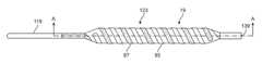
- FIG. 1Ais a plan view of an embodiment of an electroporation balloon catheter of the present invention with a balloon and electrode assembly at the distal portion of the catheter.
- FIG. 1Billustrates an enlarged partial plan view and a cross-sectional view of the catheter shaft of FIG. 1A .
- FIG. 2depicts a plan view of the balloon and electrode assembly of the electroporation balloon catheter of the present invention.
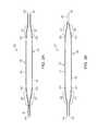
- FIG. 3Ais a plan view of a first longitudinal electrode of the electrode assembly.
- FIG. 3Bis a plan view of a second longitudinal electrode of the electrode assembly.
- FIG. 4Aillustrates a plan view of the electrode assembly comprising the first and second longitudinal electrodes.
- FIG. 4Bdepicts end views of the electrode assembly taken from lines A-A and B-B of FIG. 4A .
- FIGS. 5A and 5Bdepict partial cross-sectional views of the proximal section of the balloon and electrode assembly taken along lines A-A of FIG. 2 .
- FIGS. 6A and 6Bdepict partial cross-sectional views of the distal section of the balloon and electrode assembly taken along lines B-B of FIG. 2 .
- FIGS. 7A and 7Billustrate end views of the balloon and electrode assembly taken along lines C-C and D-D of FIG. 1A .
- FIG. 8Aillustrates a plan view of the combined balloon/electrode assembly in an expanded position.
- FIG. 8Billustrates a plan view of the combined balloon/electrode assembly shown in a collapsed position.
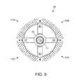
- FIG. 9shows an end view of the balloon electrode assembly taken along lines D-D of FIG. 1 illustrating the electrical current generated between the electrodes.
- FIG. 10is a plan view of another embodiment of an electroporation balloon catheter of the present invention with a balloon and electrode assembly at the distal portion of the catheter.
- FIG. 11illustrates an enlarged cross-sectional view of the catheter shaft of FIG. 10 taken along lines A-A.
- FIG. 12is a plan view of the balloon and electrode assembly of the electroporation balloon catheter of FIG. 10 .
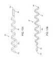
- FIG. 13Ais a plan view of a first spiral electrode of the electrode assembly of FIG. 10 .
- FIG. 13Bis a plan view of the second spiral electrode of the electrode assembly of FIG. 10 .
- FIG. 14illustrates a plan view of a spiral electrode assembly comprising the first and second spiral electrodes.
- FIG. 15Ais a partial longitudinal cross-sectional view of the distal portion of the electroporation catheter taken along lines A-A of FIG. 12 illustrating the electrodes, shaft and balloon.
- FIG. 15Bis a partial longitudinal cross-sectional view of the distal portion of the electroporation catheter taken along lines A-A of FIG. 12 after 90 degree rotation from FIG. 15A .
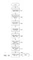
- FIG. 16is a flowchart representing the steps of one method of the invention.
- FIG. 17A-Edepicts the steps in the method of treatment of restenosis within a vessel.
- FIG. 18A-Dillustrate other embodiments of the electrode configurations of the electrode balloon catheter of the current invention.
- FIGS. 19-23relate to Example 1.
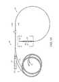
- FIG. 19includes FIG. 19A which is a schematic drawing and FIG. 19B which is a photograph of a custom made electrode clamp employed to induce irreversible electroporation of the carotid artery.
- FIG. 19Bshows a photograph where the clamp is used for clamping the carotid artery, where the distance between electrodes was approximately 0.3 mm
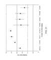
- FIG. 20shows a graph of examples of conductance of the arterial wall during repetitive direct current pulses. Conductance is measured only during the 100 microseconds pulses and here it is displayed without the 100 ms intervals between pulses. Two cases are shown: a trial in which successful irreversible electroporation was achieved and a case in which the voltage pulses apparently were not able to cause electroporation
- FIG. 21Ais an actual photograph of a right common carotid artery. This slide is an example of the appearance of a normal right carotid artery. (L—Intra-arterial lumen; TM—Tunica media).
- FIG. 21Bis an actual photograph of a left common carotid artery 28 days after intimal damage, showing high neointima to media ratio.
- LIntra-arterial lumen
- TMNeurointimal Formation
- FIG. 21Cis an actual photograph of a left common carotid artery 28 days after intimal damage in an IRE treated rat, showing the scarcity of neointimal formation compared with FIG. 21B (L—Intra-arterial lumen; Arrow—minimal neointimal formation).
- FIG. 22Ais an actual photograph of a right common carotid artery. This slide is an example of the appearance of a normal control endothelial layer (L—Intra-arterial lumen; TM—Tunica media; Arrow—Endothelial layer).
- LIntra-arterial lumen
- TMTeunica media
- ArrowEndothelial layer
- FIG. 22Bis an actual photograph of a left common carotid artery, 28 days after intimal damage and IRE. This slide shows the overall preserved appearance of the endothelial layer.
- AIntra-arterial lumen artifact
- TMTumor media
- ArrowEndothelial layer
- FIG. 22Cis an actual photograph of a left common carotid artery, 28 days after intimal damage. This slide shows the damaged and irregular endothelial layer in the control group. (L Intra-arterial lumen; NI—Neointimal Formation; Arrow —irregular endothelial layer).
- FIG. 23is a Table showing results obtained on 8 animal models.
- FIGS. 24-32relate to Example 2.
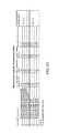
- FIG. 24is a Table showing the eight different electroporation parameters used in this study. Groups differ in the magnitude of the applied electric field, the number of the pulses and their frequency. All pulses were square pulses, 100 ⁇ s in length. Frequency of 10 Hz was used for the 10-pulse protocols, and was reduced to 4 Hz for 45 or 90 pulse protocols to prevent significant heating.
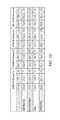
- FIG. 25is a Table showing data of the four different 10-pulse protocols. All data are shown as average with standard deviation, and include the percentage of IRE values compared with control.
- Cell numberis the average number of VSMC nuclei identified in the Tunica Media. Concentration is the ratio between the number of cells and the area of the Tunica Media (10 ⁇ 3 mm 2 ). Area is the total area of the Tunica Media (10 ⁇ 1 mm 2 ), and the thickness is the thickness of the Tunica Media based on five different measurements in each section in micrometers.
- FIG. 26is a Table showing data for the four different protocols with more than 10 pulses. All data are shown in the same manner as in FIG. 25 .
- FIG. 27is a bar graph showing the ablation effect due to different NTIRE protocols. The reduction in five of the groups was statistically significant (P ⁇ 0.001, bars marked with an asterisk). Ablation effect is shown as the percentage of VSMC cells in the treated artery compared with the right carotid artery of the same animal
- FIG. 28is an actual photograph showing complete ablation of VSMC population one week following NTIRE with 90 pulses of 1,750 V/cm (right picture) compared with right carotid artery of the same animal that was used as a control (left picture). Note the complete absence of VSMC cells compared with notable repopulation of the endothelial layer with endothelial cells.
- FIG. 29is a bar graph showing the effect on the sub-layer of the Tunica Media. Inner most, middle and outer sub-layers are in the first, second and third positions, left to right, respectively. Ablation effect is shown as the percentage of VSMC cells in the sub-layer compared with the same sub-layer in the right carotid artery of the same animal. Note the relative sparing of the inner most VSMC cells in all five groups, compared with the complete ablation of VSMC in the outer layers with 1750 V/cm (second and third groups in FIG. 29 ).
- FIG. 30shows three actual photographs taken at magnification ( ⁇ 40) of the effect of NTIRE on blood vessels after one week.
- Top pictureshows a control artery
- middle pictureshows a partial effect due to 45 pulses of 875 V/cm (Group 6)
- lower pictureshows a complete ablation of the arterial VSMC population.
- all surviving VSMCare located in the innermost layer of the Tunica Media.
- the lower pictureshows the repopulation of the endothelial layer with endothelial cells, compared with total absence of VSMC.
- FIG. 31is a graph showing the conductance change during NTIRE application.
- X-axisshows the eight study groups.
- Y-axisshows the change as the ratio between the conductance value measured at the last electroporation pulse and the value at the first pulse.
- Groups 3 and 4(875 ⁇ 10 and 437.5 ⁇ 10, respectively) show no change in conductivity, which correlates well with the no ablation effect (see FIG. 28 ).
- Group 2 (1,750 ⁇ 10)shows partial reduction in conductivity, correlating well with minor ablation effect.
- FIG. 32shows six actual photographs of tissues subjected to histology staining.
- Left columnshows control arteries and right column shows IRE-treated arteries.
- Top rowEMG stain showing undamaged elastic fibers in IRE-treated arteries (elastic Van Gieson, ⁇ 40).
- Middle rowMasson Trichrome stain showing mild fibrosis in the perivascular area with dominance of collagen fibers in the Tunica Media of the IRE-treated Arteries (Masson Trichrome, ⁇ 40).
- Lower rowNegative staining of both arteries with CD34 antibodies at higher magnification ( ⁇ 60). Note the similar morphology and distribution of the endothelial cells.
- a target areaincludes a plurality of such target area
- reference to “restenosis”includes reference to one or more areas of restenosis and equivalents thereof known to those skilled in the art, and so forth.
- Electroporationis defined as a phenomenon that makes cell membranes permeable by exposing them to certain electric pulses. As a function of the electrical parameters, electroporation pulses can have two different effects on the permeability of the cell membrane.
- the permeabilization of the cell membranecan be reversible or irreversible as a function of the electrical parameters used.
- Reversible electroporationis the process by which the cellular membranes are made temporarily permeable. The cell membrane will reseal a certain time after the pulses cease, and the cell will survive.
- Reversible electroporationis most commonly used for the introduction of therapeutic or genetic material into the cell. Irreversible electroporation, also creates pores in the cell membrane but these pores do not reseal, resulting in cell death.
- Irreversible electroporationhas recently been discovered as a viable alternative for the ablation of undesired tissue. See, in particular, PCT Application No. PCT/US04/43477, filed Dec. 21, 2004.
- An important advantage of irreversible electroporation, as described in the above reference application,is that the undesired tissue can be destroyed without creating a thermal effect.
- tissueis ablated with thermal effects, not only are the cells destroyed, but the elastin, collagen and other extra-cellular matrix components (tissue scaffolding) of blood vessels are also destroyed. This thermal mode of damage detrimentally affects the tissue, that is, it destroys the vasculature structure and bile ducts, and produces collateral damage.
- Irreversible and reversible electroporation without thermal effect to ablate tissueoffers many advantages.
- One advantageis that it does not result in thermal damage to target tissue or other tissue surrounding the target tissue.
- Another advantageis that it only ablates cells and does not damage blood vessel structure itself. Accordingly, irreversible electroporation may be used to treat the inner wall of a blood vessel during or immediately following balloon angioplasty to prevent the re-growth of endothelial cells.
- Human arteries and veinsare comprised of three layers; the intima which is the thinnest and innermost layer; the media which is the thickest and middle layer; and an outer adventitia layer comprised of connective tissue.
- the medial layeris comprised mainly of smooth muscle cells which play a prominent role in re-stenosis of previously treated vessels. It is believed that in reaction to the vessel wall trauma associated with balloon angioplasty, the smooth muscle cells within the medial layer proliferate causing a thickening of the overall vessel wall and consequently, a reduction in the luminal diameter of the vessel. This is also known as hyperplasia of the smooth muscle cells.
- smooth muscle cells of the vesselare selectively destroyed without damage to the non-cellular tissue of the vessel.
- irreversible electroporationis a non-thermal treatment modality
- adjacent structuresare not damaged by the electrical field.
- the connective non-cellular tissue of the vesselcollagen, elastin and other extra-cellular components
- the treated vessel wallis gradually repopulated with endothelial cells that regenerate over a period of time but do proliferate or thicken into a stenotic lesion.
- the electroporation catheter of the current inventionmay be used to treat native stenotic lesions as well as stenoses or strictures of other bodily organs.
- Target treatment areasmay include claudication of peripheral arteries, stenotic buildup in dialysis fistulas and grafts, carotid artery stenosis and renal artery strictures as well as venous lesions.
- non-vessel lumensincluding but not limited to biliary tract blockages, bowel obstructions, gastric outflow strictures as well as any other bodily lumen narrowing or occlusion.
- a method of treating stenotic lesionswherein an electrical field ablates vessel wall cells to prevent re-growth of the lesion after angioplasty or other treatment.
- an electrical fieldablates vessel wall cells to prevent re-growth of the lesion after angioplasty or other treatment.
- the method described hereinmay be used in lieu of drug-eluting stents which have demonstrated only limited success in preventing stent re-stenosis.
- the electrical parametersmay be set to create an electrical field that temporarily or reversibly electroporate cellular structures.
- the smooth muscle cells comprising the target lesionwill temporarily permiablize, allowing the transport of a drug into the intracellular structure.
- Drugsmay include anti-stenotic agents that may further prevent smooth cell proliferation or cytotoxic drugs, such as a chemotherapy agent if the stricture is caused by a cancerous growth.
- Some examples of devices which could be modified to obtain the basic objects of the inventioninclude the balloon catheter device of U.S. Pat. No. 7,150,723 teaching a medical device including guidewire and balloon catheter for curing a coronary artery.
- Another catheter device which might be modified to utilize the aspects of the inventionis the device of U.S. Pat. No. 7,273,487 disclosing a balloon catheter having a multi-layered shaft with variable flexibility.
- Still another balloon catheter deviceis taught within U.S. Pat. No. 7,351,214 disclosing a steerable balloon catheter.
- Yet another deviceis taught within U.S. Pat. No. 7,481,800 disclosing a triple lumen stone balloon catheter and method.
- the present inventionis not specific to any of these embodiments and other embodiments can be used to provide various catheter configurations which include first and second electrodes connected to a power source which provides to the electrodes a sufficient amount of electrical energy to carry out irreversible electroporation on substantially all of the cells in the vessel target area without subjecting the target area or surrounding area to thermal damage.
- Irreversible Electroporationis a non-thermal, non-pharmacological cell ablation method.
- IREutilizes a sequence of electrical pulses that produce permanent damage to tissue within a few seconds. Examples provided here show that the left carotid arteries of 8 rats underwent in vivo intimal damage using 2 Fogarty angioplasty catheters. The procedure was immediately followed by IRE ablation in 4 rats, while the remaining 4 were used as the control group.
- the IRE ablationwas performed using a sequence of 10 direct current pulses of 3800 V/cm, 100 ⁇ s each, at a frequency of 10 pulses per second, applied across the blood vessel between two parallel electrodes.
- the electrical conductance of the treated tissuewas measured during the electroporation to provide real time feedback of the process.
- Left carotid arterieswere excised and fixated after a 28-day follow-up period.
- Neointimal formationwas evaluated histologically.
- the use of IREwas successful in 3 out of 4 animals in a way that is consistent with the measurements of blood vessel electrical properties.
- the integrity of the endothelial layerwas recovered in the IRE-treated animals, compared with control.
- the present inventionshows that the in vivo results of attenuation of neointimal formation using IRE.
- the inventionprovides a method which uses IRE to attenuate neointimal formation after angioplasty damage in a mammal such as a human and provides a method of treating coronary artery restenosis after balloon angioplasty.
- FIG. 1Aillustrates a plan view of an embodiment of the electroporation balloon catheter 10 of the current invention.
- Catheter 10is comprised of a hub 13 , a flexible catheter shaft 15 extending distally from hub 13 to an expandable member such as a balloon 19 and terminating at catheter distal tip 17 .
- Hub 13includes a port opening 21 in communication with a shaft lumen (not shown) for the injection and aspiration of fluid to inflate and deflate the balloon 19 during use.
- Shaft 15extends from hub 13 distally through the interior of balloon 19 before terminating in distal tip 17 .
- Balloon 19is coaxially arranged around catheter shaft 15 near the distal end and is shown in an expanded state.
- catheter 10may also include a side-arm extension on hub 13 with an opening to allow the insertion of a guidewire to facilitate tracking through the vessel. Extending from hub 13 are electrical cable wires 9 which terminate in connectors 11 . Connectors 11 are connected to an electrical generator or electrical power source (not shown) to provide an electrical current to a first and second longitudinal electrodes 25 and 27 , which are positioned in a longitudinal arrangement around the outer surface of balloon 19 .
- FIG. 1Bincludes the exploded partial plan view from “A” of FIG. 1A and an enlarged cross-sectional view of the shaft 15 taken along lines B-B of FIG. 1A .
- shaft 15is comprised of an electrically conductive tubing 110 with a through lumen 41 , an insulating layer 112 coaxially surrounding tubing 110 and an outer insulative layer 116 coaxially surrounding the inner insulating layer 112 . Wedged between the inner and outer insulating layers 112 and 116 , is positioned an electrically conducting wire 114 .
- Inner electrically conductive tubingis preferably comprised of a flexible nitinol shaft or other electrically conductive material to provide a pathway for the electrical current from the electrical generator to the distal end portion of the catheter when in use. It may be dimensioned with appropriate inner diameter and outer diameter. Both the inner and outer insulating layers 112 and 116 are thin layers of appropriate thickness and are made of a non-conductive material such as nylon, polyamide, PET or other plastic material.
- the electrically conductive wire 114is comprised of an electrically conductive material such as nitinol or copper and may be dimensioned at 0.004′′ thick by 0.015′′ wide.
- the inner and outer insulative layers which block electrical currentensure that the electrical current path of the inner electrically conductive tubing 110 remains isolated from the current path of the electrically conductive wire 114 .
- the catheter 10may include a separate lumen for insertion of a guidewire to assist in advancing the catheter to the target site.
- FIG. 2depicts an enlarged plan view of the distal portion of the preferred embodiment of the electroporation balloon catheter of FIG. 1A in an inflated state.
- Balloon 19is coaxially arranged around catheter shaft 15 near the distal end of the shaft.
- Expanded balloon 19includes a balloon body 35 portion of constant cross-sectional diameter, proximal 32 and distal 34 cone portions which taper inwardly away from the balloon body 35 , and proximal 37 and distal 39 neck portions of reduced diameter relative to the balloon body 35 .
- Neck portions 37 and 39are bonded to the outer surface of the catheter shaft 15 using adhesive or other bonding methods known in the art.
- electrode assembly 26which is comprised of first and second longitudinal electrodes 25 and 27 . The two longitudinal electrodes overlap to form a cage with a series of legs arranged to be in contact with the surface of the balloon when inflated.
- first and second longitudinal electrodes 25 and 27are shown prior to assembly with the balloon.
- the electrodesare comprised of suitable electrically conductive material including but not limited stainless steel, gold, silver and other metals including shape-memory materials such as nitinol.
- Nitinolis an alloy with super-elastic characteristics which enables it to return to a pre-determined expanded shape upon release from a constrained position.
- FIG. 3Awhich depicts the unassembled first longitudinal electrode 25 which includes a proximal collar 40 with lumen 49 through which is located catheter shaft 15 when assembled.
- Flexible first and second electrode legs 44 and 42extend from collar 40 in a distal direction to leg end portions 48 and 46 respectively.
- the legs 44 and 42take on the general profile of the expanded balloon shape as can be seen by tapered portions 51 , 52 , 53 and 54 which correspond with the proximal and distal balloon cone sections 32 and 34 .
- a plurality of electrically insulative elements 105 and 107covers portions of the first longitudinal electrode 25 .
- the electrically insulating elements 105 and 107may be of a PET, polyamide or other similar material in the form a tubular structure or heat-shrinkable material. As shown in FIG.
- insulative element 105covers the proximal collar 40 and proximal tapering portions 51 and 52 of electrode legs 44 and 42 .
- the insulating element 105terminates at a point on the electrode legs 44 and 42 that correspond with the junction of the proximal balloon cone and body (reference FIGS. 2A and 2B ).
- insulative element 107covers the distal portions of legs 44 and 42 and extend proximally from distal leg ends 48 and 46 , taper portions 53 and 54 to a point on the legs 44 and 42 that correspond with the junction of the distal balloon cone and balloon body.
- the arrangement of the insulative elements over the legs 44 and 42create an active electrode portion 45 and 47 through which electrical current will freely pass.
- FIG. 3Billustrates the unassembled second longitudinal electrode 27 , which is comprised of a distal collar 55 including lumen 65 through which the distal portion of catheter shaft 15 is positioned when assembled. Extending proximally from collar 55 are a first electrode leg 57 and second electrode leg 59 which terminate in proximal leg ends 61 and 63 respectively. Electrode legs 57 and 59 take on the general profile of the expanded balloon shape as can be seen by proximal tapered portions 69 and 70 which correspond with the proximal balloon cone section 32 . Distal tapered portions 67 and 68 correspond with the distal balloon cone section 34 . Proximal and distal outer insulative layers 101 and 103 cover portions of longitudinal electrode 27 . As shown in FIG.
- distal insulative layer 103covers the distal collar 55 and tapered portions 67 and 68 .
- Distal insulative layer 103terminates at a point on the legs 57 and 59 which correspond with the junction of the distal balloon cone and balloon body (reference FIGS. 2A and 2B ).
- proximal outer insulative layer 101covers the proximal portions of legs 57 and 59 and extends from proximal leg ends 61 and 63 , tapered portions 69 and 70 to a point on the legs 57 and 59 that correspond with the junction of the proximal balloon cone and balloon body.
- the straight, un-insulated portion of legs 57 and 59are the active electrode portions 77 and 79 . While the insulated portions of electrode 27 will not conduct electrical current, the active electrode portions 77 and 79 of longitudinal electrode 27 will generate a therapeutic electrical field when electrical energy from the electrical generator is applied to the assembly.
- first and second longitudinal electrodes 25 and 27are in an overlapping arrangement relative to each other as shown in FIG. 4A , which illustrates the electrode assembly 26 with second longitudinal electrode 27 rotated 90 degrees clockwise from the view in FIG. 3B .
- Second longitudinal electrode 27is positioned in an overlapping relationship with first longitudinal electrode 25 such that collar 55 of second electrode 27 extends distally beyond the leg ends 48 and 46 of first electrode 25 .
- collar 40 of first electrode 25extends proximally of leg ends 61 and 63 of second longitudinal electrode 27 .
- the active electrode portions 45 , 47 , 77 and 79 of both electrodes 25 and 27are in alignment with each other relative to the longitudinal axis of the electrode assembly 26 and together form an active electrode region 115 .
- the electrode assembly 26 of FIG. 4Ais held together as a single unit at the proximal 40 and distal 55 collars. Specifically, distal portions of legs 44 and 42 of electrode 25 are immovably attached to the outer surface of collar 55 of second longitudinal electrode 27 . Conversely, proximal sections of legs 57 and 59 of electrode 27 are immovably attached to the outer surface of collar 40 of first longitudinal electrode 25 . Various methods known in the art such as welding, bonding, or application of adhesive may be used to form the attachment between the collars and legs.
- FIG. 4Billustrate end views of the electrode assembly 26 taken from line A-A and B-B of FIG. 4A .
- proximal collar 40is shown with through lumen 49 and surrounding outer insulative layer 105 .
- Outwardly tapering sections 51 and 52 with insulative layer 105 of first longitudinal electrode 25are shown extending distally from collar 40 to reach a larger constant diameter of legs 44 and 42 .
- the proximal most ends 61 and 63 of second electrode 27are shown bonded to the outer surface of collar 40 /insulative layer 105 at weld joints 73 and 75 respectively.
- Outwardly tapering sections 69 and 70extend horizontally and distally from collar 40 to reach a larger constant diameter of legs 57 and 59 respectively.
- a partial view of distal collar 55 of second longitudinal electrode 27 with insulative layer 103is also shown.
- Detail B-B of FIG. 4Aillustrates an end view of electrode assembly 26 taken along line B-B in FIG. 4A .
- Distal collar 55is shown with through lumen 65 and outer insulative layer 103 .
- a partial view of proximal collar 40which is of a smaller diameter than distal collar 55 , is shown within lumen 65 .
- Outwardly tapering sections 67 and 68 of conducting element 27are shown extending from collar 55 to reach a larger constant diameter of legs 57 and 59 .
- the distal ends 48 and 46 of first longitudinal electrode 25are shown bonded to the collar 55 of weld joints 62 and 64 respectively. Other attachment methods may be used to create joints 62 and 64 , as is known in the art.
- Outwardly tapering sections 53 and 54 of electrode 25are shown extending vertically and proximally from collar 55 to reach a larger constant diameter of legs 44 and 42 respectively.
- first and second longitudinal electrodes 25 and 27each may carry an opposite polarity electrical charge.
- first electrode 25may carry a negative electrical charge and second electrode 27 may carry a positive electrical charge.
- an electrical fieldis created between active electrode zones 115 of the first and second electrodes 25 and 27 which are of opposite polarity.
- an electrical currentmay be created between positively charged leg 57 of second electrode 27 and negatively charged leg 44 of first electrode 25 .
- an electrical currentmay be created between legs 44 and 59 , between legs 59 and 42 , and between legs 42 and 57 .
- the resulting electrical field created by the application of electrical energy of opposite polarities to the legs of the first and secondcreates a substantially 360 degree electrical field zone surrounding the balloon, which when inflated is in contact with the inner wall of the vessel. Consequentially, the entire circumference of the inner wall of the target vessel is subject to a therapeutic electrical field.
- the electrical fieldis restricted to the active electrode portions 45 , 47 , 77 , and 79 of the longitudinal electrodes 25 and 27 because these portions are not insulated.
- the un-insulated portions of electrodes 25 and 27correspond to the constant diameter body portion of the balloon.
- Electrodes 25 and 27that correspond to the proximal and distal balloon cones 32 , 34 and necks 37 , 39 are insulated and accordingly will not generate and electrical field. Only the vessel wall is treated; any blood present within the vessel lumen is not impacted by the treatment as no electrical field is generated from the insulated portions of the device.
- FIGS. 5A and 5Billustrate details of the two electrical pathways of electrical current to the active electrode zone 115 (reference FIG. 4A ).
- FIG. 5Aillustrates an enlarged cross-sectional partial view of proximal section electrode assembly 26 showing the electrical connection between the wire 114 and the second electrode 27 , which in one embodiment may be a positive electrical pathway.
- Catheter shaft lumen 41is formed by electrically conductive shaft tubing 110 , which includes an outer insulative layer 112 , to which collar 40 and proximal balloon neck 37 are attached.
- electrically conductive wire 114Positioned on the surface of insulated shaft 110 is electrically conductive wire 114 , which is positioned between insulative layer 112 of the shaft and outer insulative layer 116 to ensure isolation of the positive and negative electrical pathways.
- electrically conductive wire 114extends outwardly and distally over collar 40 and over electrode leg 57 .
- the wireis positioned between electrically insulative layer 101 of electrode leg 57 and an outermost insulating layer 116 .
- Layer 116which extend from hub 13 of catheter 10 (reference FIG. 1A ) and over the distal portion of electrode assembly 26 , not only ensures that wire 114 is electrically insulated from conductive shaft tubing 110 , but also serves to encompasses the various individual component pieces comprising the distal portion of assembly 26 .
- insulation layer 101has been removed from the distal portion of leg 57 so as to allow for a direct electrical connection between wire 114 and leg 57 of electrode 27 .
- Wire 114is attached directly to leg 57 by bonding, welding, soldering or other known means at attachment zone 141 .
- the positive polarity electrical currentis passed from the generator to the electroporation device 10 , electrical energy is transmitted through the shaft by way of the wire 114 , to the leg 57 at the un-insulated attachment zone 141 and to the remaining portions of second electrode 27 (reference FIG. 3B ).
- the active electrode portions 77 and 79 of legs 57 and 59 (reference FIG. 4A ) of longitudinal electrode 27is energized with positive polarity.
- FIG. 5Bdepicts the proximal section details of the electroporation catheter 10 rotated longitudinally 90 degrees from the FIG. 5A orientation.
- This cross-sectional viewillustrates the second electrical pathway, which in one embodiment is a negative polarity current.
- Negative electrical current originating from an electrical generatoris transmitted through the electrically conductive shaft tubing 110 to collar 40 of electrically conductive element 25 .
- shaft 110includes outer insulative layer 112 for the majority of the shaft length, the layer 112 is removed allowing for direct attachment between shaft 110 and collar 40 at region 111 .
- Region 111may include a weld bond. The resulting contact region 111 creates an electrical current pathway between the generator and longitudinal electrode 25 .
- the distal portion of electrode assembly 26is illustrated in two enlarged, cross-sectional partial views of FIG. 6 .
- the second enlarged viewis shown at a 90 degree longitudinal rotation from the first view.
- Electrically conductive shaft 110is shown with outer insulative layer 112 which extends through the electrode assembly 26 to a distal tip end 17 .
- Coaxially arranged around the insulated shaft 110 / 112is the distal neck 39 of balloon 19 .
- Collar 55 of longitudinal electrode 27also coaxially surrounds shaft 110 .
- Collar 55is proximate to but not in contact with insulated shaft 110 / 112 .
- an annular gap 66can be made to exist between the two components.
- Annular gap 66extends from collar 55 proximal edge 104 to collar distal edge 108 .
- the purpose of gap 66is to allow electrode assembly 26 to slide freely over shaft 110 as it foreshortens and lengthens during balloon expansion and deflation, as will be explained in more detail with reference to FIG. 8 .
- Also shown in the first view of FIG. 6are inwardly bowing leg portions 53 and 54 of legs 44 and 42 . Insulated legs 44 and 42 are attached to insulated collar 55 at attachment regions 81 and 83 respectively. Adhesive or other known attachment mechanisms may be used to form the connection. Due to the insulative layers 103 of collar 55 and insulative layer 103 of legs 44 and 42 , attachment regions 81 and 83 are not electrically conductive and no direct electrical current pathway exists between collar 55 and electrode assembly 25 .
- FIG. 7illustrates end views of the balloon 19 /electrode assembly 26 taken along lines C-C and D-D of FIG. 1A .
- proximal balloon cone 32 of balloon 19is shown in an inflated position.
- Electrode legs 42extend in a vertical over the surface of balloon 19 .
- Electrically conductive shaft tubing 110surrounds shaft lumen 41 .
- Collar 40is in electrical connection with shaft 110 by weld region 111 .
- Collar 40is coaxially surrounded by electrode assembly insulative layer 101 which electrically isolates collar 40 from wire 114 .
- Outer insulative layer 116coaxially surrounds the shaft assembly and electrically conductive wire 114 .
- Also shownis an end view of insulative layer 116 as it extends over leg ends 61 and 63 .
- Detail D-D of FIG. 7depicts an end view of the catheter assembly taken along lines D-D of FIG. 1A .
- the distal tip 17 of shaft 19is positioned within lumen 65 of collar 55 which is also shown as annular gap 66 .
- Electrode legs 57 and 59extend from collar 55 in a horizontal direction over the surface of balloon 19 . Ends 48 and 46 of electrode legs 44 respectively are attached to collar 55 at weld joints 64 and 62 .
- FIG. 8A-Billustrates the longitudinal movement of electrode assembly 26 relative to the catheter shaft 19 during use.
- FIG. 8Adepicts catheter 10 with balloon 19 inflated.
- Assembly 26is positioned in a surrounding relationship over inflated balloon 35 .
- Legs 44 and 47are shown with proximal taper portions 51 and 52 bowing radially outward and away from shaft 15 .
- Distal taper portions 53 and 54are also in an expanded state.
- the electrode assembly 26is comprised of shape memory material such as nitinol which returns to a pre-determined shape upon release. As such, assembly 26 may retain its expanded profile as shown in 8 A even if the balloon is not inflated.
- the distal edge 108 of collar 55is positioned a distance L 1 from the catheter distal tip 17 .
- electrode assembly 26In a constrained state, as shown in FIG. 8B , electrode assembly 26 is in a collapsed position around shaft 15 and balloon 19 . Legs 44 , 47 , 57 and 59 (not visible) become linear in profile with all tapering portions 51 , 52 , 53 and 54 flattening out so that they are positioned parallel with the shaft. When the assembly is collapsed, collar 55 slides in a distal direction. Movement of the electrode assembly 26 relative to the shaft 19 and balloon 25 occurs because the distal portion assembly 26 is not attached to shaft 15 at collar 55 . When electrode assembly 26 is completely collapsed, the leading edge 108 of collar 55 is positioned a distance L 2 away from catheter distal tip 17 . Total distal movement of the assembly collar 55 is for a length of L 1 -L 2 . More specifically, catheter 10 is typically inserted into a target vessel through a sheath or other introducer device.
- FIG. 9illustrates the electrical current flow pattern from an end view of the electroporation catheter device 10 .
- Electrical energywill be transmitted from an electrical generator through shaft tubing 110 to electrode legs 42 and 44 of electrode assembly 25 as previously described.
- this electrical pathwayis of a positive polarity as indicated by the “+” signs in FIG. 9 .
- Electrical energy of a negative polaritymay be transmitted through wire 114 to longitudinal electrode assembly 27 through wire 114 to leg 59 connection 111 .
- this second electrical pathwayis of a negative polarity as indicated by the “ ⁇ ” signs in FIG. 9 .
- the electrodescan be electrically energized one pair at a time and selectively switched to cover all four pairs.
- all electrodesare simultaneously energized, causing electrical current to flow from positive polarity legs to negative polarity legs.
- electrical currentwill flow from leg 44 with a positive polarity to leg 59 with a negative polarity, creating an electrical field zone 168 .
- Electrical current from leg 59will also flow to negative polarity leg 57 , creating an electrical field zone 174 .
- positive polarity leg 42will transmit electrical current to both negative polarity legs 57 and 59 , creating electrical fields 172 and 170 .
- the flow of electrical currentwill be restricted to the un-insulated portions of the electrode legs, which correspond with maximum diameter of the inflated balloon 19 .
- the resulting combined electrical fields created by the application of electrical energy of opposite polarities to the electrode legs 44 , 59 , 42 and 57create a substantially 360 degree electrical field zone surrounding the balloon body 35 .
- this combined electrical field zoneextends radially outward and into the inner wall of the vessel. In this manner, the entire circumference of the inner wall of the target vessel is subject to a therapeutic electrical field.
- Catheter 121is comprised of a hub 13 , a catheter shaft 119 extending distally to a balloon 19 and terminating at a catheter open distal end 139 , which is sized to pass a guidewire.
- Balloon 19is coaxially arranged around catheter shaft 119 near the distal end and is shown in an expanded state.
- Hub 3may include port opening 13 and side-arm extension opening 12 to allow the insertion of a guidewire and injection of fluid to inflate the balloon 19 .
- Extending from hub 3are electrical cable wires 9 which terminate in connectors 11 .
- Connectors 11are connected to an electrical generator (not shown) to provide an electrical current to the spiral electrode assembly 123 which is coaxially arrangement over balloon 19 .
- FIG. 11represents a cross-sectional view of the catheter shaft 119 taken along lines A-A of FIG. 10 .
- Shaft 119which in one embodiment has a sufficient outer diameter so that it may include four lumens.
- Guidewire lumen 125may be approximately 0.039′′ in diameter and in communication with side arm extension opening 1 to accept a standard guidewire which is used for tracking device 121 to the target location within a vessel.
- Inflation/deflation lumen 131is in communication with hub opening 21 for injection and withdrawal of fluid to and from the balloon 35 interior.
- First and second electrode wire lumens 127 and 129are configured to contain electrode wires 133 and 135 respectively. Wires 133 and 135 are electrically insulated from each other by inner shaft septum 137 , which is comprised of a plastic or other non-conductive material.
- FIG. 12illustrates an enlarged plan view of the distal end section of the electroporation balloon catheter 121 which is shown inflated.
- Catheter shaft 119extends into and through balloon 35 , terminating at open distal tip 139 .
- spiral electrode assembly 123Helically surrounding the balloon surface is spiral electrode assembly 123 , which is comprised of a first and second spiral electrode 85 and 87 .
- first spiral electrode element 85is of a positive polarity and second electrode 87 is of a negative polarity.
- Spiral electrode 85is connected to first electrode wire 133 and spiral electrode 87 is connected to second electrode wire 135 .
- First spiral electrode 85shown in FIG. 13A , is comprised of a distal collar 89 containing a lumen 144 , a spiral shaped body 91 of an expanded diameter relative to the collar 89 and a proximal tail 93 .
- a second spiral electrode 87is shown in FIG. 13B .
- Second spiral electrode 87is comprised of a proximal collar 95 with through lumen 146 , a spiral shaped body 97 of an expanded diameter relative to collar 95 , and a distal tail 99 .
- the spiral shaped bodies 91 and 97are formed of a series of helical turns 148 .
- the two spiral electrodes 85 and 87may be assembled together in an overlapping relationship on the same longitudinal axis to form a double helix was shown in FIG. 13C .
- the plurality of helical turns 148 of the first spiral electrode 85are positioned adjacent to corresponding helical turns 148 of the second spiral electrode 87 .
- Electrode 85 and 87may be comprised of any conductive material known in the art.
- the electrodesmay be formed of a nitinol tube which has been laser cut and memory set to the desired spiral profile.
- electrodes 85 and 87may be comprised of a conductive ink which is applied in the desired pattern to the exterior balloon surface.
- the conductive inkmay be comprised of an adhesive binder material loaded with silver particles. Other conductive materials such as gold or steel may also be used.
- the conductive inkmay be applied in the desired pattern to the balloon surface using a pen-like applicator and a rotating lathe type fixture. The application of conductive ink may be between 0.001′′ and 0.002′′ in thickness.
- FIG. 15Aillustrates an enlarged cross-sectional view of the spiral electrode assembly 123 positioned on the outer surface of the balloon.
- the cross-sectional viewis taken along lines A-A of FIG. 12 .
- Shaft 119is includes a guidewire lumen 125 and an inflation lumen 131 .
- the guidewire lumen 125extends from catheter hub 3 through shaft 119 exiting at open distal end 139 .
- the inflation lumen 131also extends from catheter hub 13 (reference FIG. 10 ) but terminates within balloon interior 23 at inflation lumen dead end 29 .
- a fluid or other inflation mediumis injected into hub 13 through hub opening 21 , directed distally within inflation lumen 131 and into the balloon interior 23 through inflation lumen side port 31 . This fluid path is also used for withdrawing fluid to deflate the balloon prior to withdrawal of the device from the target vessel.
- First spiral electrode 85is positioned over balloon 19 with distal electrode collar 89 coaxially surrounding distal balloon neck 39 .
- first spiral electrode 85is of a positive polarity. Extending proximally from electrode collar 89 , electrode section 91 a partially surrounds balloon cone 34 and comprises the beginning of the first helical turn. The spiral electrode 85 pattern continues proximally along the surface of balloon body 35 , as illustrated by electrode cross-sections 91 b , 91 c , 91 d , 91 e and 91 f . The proximal tail 93 of the first electrode spiral is not visible, but is positioned adjacent to proximal balloon cone 32 .
- a second or negative spiral electrode 87includes a proximal collar 95 that coaxially surrounds balloon proximal neck 37 . Extending distally from collar 95 , electrode section 97 a partially surrounds proximal balloon cone 32 and comprises the beginning of the spiral pattern. The negative electrode spiral pattern continues proximally along the surface of the balloon body 35 , as illustrated by electrode cross-sections 97 b , 97 c , 97 d , 97 e and 97 f . The distal tail 99 of negative spiral electrode is not visible, but is positioned adjacent to the balloon cone 34 .
- the resulting surface pattern of the combined spiral electrodes 85 and 87is a double helix configuration with alternating polarity electrodes positioned along the balloon surface.
- electrical current of opposite polarityis applied to electrodes 85 and 87 , an electrical field is generated between the positive spiral electrode 85 and the negative spiral electrode. With the electrical current flowing from positive to negative, an electrical field is created between each set of helical turns.
- electrical currentwill flow from 91 a to 97 f , from 91 b to 97 e and from 91 c to 97 d .
- the effect of this electrical field patternis that the majority of the balloon surface is within the active electrical field. This is advantageous in that since the electrical field encompasses substantially the entire balloon surface, the resulting ablation zone will uniformly encompass the vessel wall area corresponding to the balloon surface.
- FIG. 15Billustrates an enlarged cross-sectional view of the spiral electrode assembly 123 positioned on the outer surface of the balloon 35 and represent a 90 degree rotation of the cross-sectional view of FIG. 15A .
- Electrically conductive wires 133 and 135originate within cable connectors 11 and extend distally within cable lines 9 and enter shaft lumens 127 and 129 through hub 3 . Both wires are comprised of an electrically conductive material such as silver, gold, copper or other metal.
- wires 133 and 135have a flat profile with dimensions of approximately 0.004′′ thick and 0.015′′ wide. In another embodiment the wires may be circular in cross-sectional diameter.
- An insulative outer layermay surrounds the bare wire. The insulative layer may be of a plastic material such as nylon.
- Each wirehas a dedicated lumen within shaft 119 , as shown in FIG. 15B .
- Electrically conductive wire 133is coaxially arranged within lumen 127 and.
- Electrically conductive wire 135is coaxially arranged with lumen 129 .
- the separate, dedicated wire lumens 127 and 129provide additional assurance that the electrically conductive wire 133 and 135 which are of opposite polarity when charged, are electrically isolated from each other for the entire length of the catheter shaft.
- Both lumens 127 and 129terminate within shaft 119 body forming closed ended lumens so that the electrically conductive wire elements 53 and 55 and lumens 65 and 66 are not exposed to air or bodily fluids which may compromise the electrical field.
- Electrode wire 133exits electrode wire lumen 127 at side port exit 150 just proximal to electrode collar 95 .
- electrically conductive wire 127is attached to the outer surface of collar 95 , whereby completing the electrical pathway between the electrical generator and the spiral electrode 123 .
- Wire 133is attached to the spiral electrode collar 95 using either a conductive epoxy or other attachment method known in the art.
- electrode wire 135exits wire lumen 129 at a side port exit 152 just distal to the electrode collar 89 .
- electrically conductive wire 129Upon exit, electrically conductive wire 129 is attached to the outer surface of collar 89 , whereby establishing the electrical pathway to the spiral electrode 85 .
- electrically conductive wire 135may exit wire lumen 129 within the balloon interior 45 .
- the insulated wire 135is sandwiched between the distal balloon neck 39 and the outer surface of catheter shaft 119 , exiting from the distal end of balloon neck 39 to make contact with electrically conductive collar 89 .
- FIG. 18Aillustrates an alternative embodiment of the balloon electrode assembly 401 comprising two electrodes 403 and 405 of opposite polarity.
- Proximal electrode 403covers the proximal neck, cone and a portion of the body of the balloon 407 and in one embodiment is comprised of a conductive ink coating. Other metallic materials may be used to manufacture the electrodes.
- Distal electrode 405covers the distal neck, cone and a portion of the balloon 407 body.
- the exposed balloon body portion 409represents the active electrode zone.
- the electrode materialis selected so as to be ultrasonically or fluoroscopically visible allowing the user to position the active electrode zone 409 within the lesion based on the location of the proximal electrode leading edge 411 and the distal electrode tailing edge 413 .
- balloon electrode assembly 421may include two or more electrode rings 423 and 425 of opposite polarity. Rings 423 and 425 may be attached to the outer or inner surface of balloon 427 , or may be embedded within the balloon wall. This embodiment, with the smaller active electrode zone 429 , may be advantageous when treating smaller length lesions.
- the embodiments of both FIG. 18A and FIG. 18Bare also advantageous in that these designs are easy to manufacture.
- the balloon electrode assembly 431may be comprised of a mesh or woven layer which includes electrodes as shown in FIG. 18C .
- Balloon electrode assemblyincludes helically wound strands 433 , 435 and 429 covering the surface of balloon 437 .
- Electrode strands 433 and 435circumferentially surround balloon 437 and are positioned adjacent to and parallel to each other at an angle of approximately 65 degrees relative to the longitudinal axis of the balloon.
- Strands 433 and 435may be of a conductive material such as metallic wire.
- Strand 433may be of a positive polarity and strand 435 may be negative.
- Strand 439is positioned at an opposite angle to strands 433 and 435 and runs circumferentially in a helical pattern around the balloon surface.
- Stand 439may be comprised of a non-conductive material including high strength polyester, nylon or other material so as to increase the overall strength of the balloon. In operation, electrical current will flow from the positively strand 433 to adjacent negatively charged strand 435 creating a tubular ablation zone extending radially outward from the balloon body.
- FIG. 18Dillustrates an embodiment of an electroporation balloon catheter 441 in which a series of opposite polarity prongs 447 and 449 are present in an alternating pattern across the balloon body 451 .
- Electrode 443is comprised of a plurality of distally extending prongs 447 which may be of a positive polarity. Interspaced between each positive polarity prong 447 are negatively charged proximally extending prongs 449 of electrode 445 .
- the alternating positive and negative polarity electrode prongscreate a ablation zone extending radially outward from the balloon body.
- the method of using the electroporation balloon catheter of the current invention to prevent re-stenosis of a vesselwill now be described with reference to FIGS. 16 and 17A -E.
- accessis gained to the vessel using techniques known in the art such as the Seldinger needle/guidewire access technique as shown in step 201 of FIG. 16 .
- the electroporation balloon catheteris inserted into the vessel and advanced to the target lesion ( 203 ).
- the cathetermay be inserted directly through an introducer sheath or may be inserted and advanced over a guidewire to the target vessel lesion.
- a direct percutaneous stick or cut down proceduremay be used to access the target area such as a biliary duct.
- FIG. 17Aillustrates electrode catheter 10 of FIG. 1A in position within the lumen 503 of a vessel 501 to be treated prior to angioplasty.
- Vessel 501comprises vessel wall 507 and endothelial inner layer 509 .
- the stenotic region 505which extends into the vessel lumen narrowing the luminal diameter in this area.
- Electrode balloon catheter device 10in shown in an unexpanded state within the vessel 507 lumen 503 with the electrode assembly 26 positioned adjacent to the stenotic region 505 .
- the longitudinal electrode assembly embodiment 10 of FIG. 1is shown, any of the described catheter embodiments may used with this method.
- electrical connectors 11 of the catheter 10are connected to an electrical generator ( 205 ). This completes an electrical circuit between the electrodes and the generator. This step may be performed at any time prior to applying the electrical pulses to the device.
- Treatment protocol parameterssuch as pulse width, number of pulses and voltage are set using the generator interface ( 207 ). Typical ranges include but are not limited to a voltage level of between 100-3000 volts, a pulse duration of between 20-100 ⁇ sec, and between 10 and ⁇ 500 total pulses.
- the electrical fieldwill either produce irreversible or reversible electroporation of the smooth muscle cells comprising the inner vessel wall or endothelium 509 .
- ten electrical pulses of 3500 V/cm at a frequency of 10 Hzmay be used.
- 90 electrical pulses of 1750 V/cm at a frequency of 1 Hzmay be used. These ranges ensure that damage caused by Joule heating is avoided.
- conductance of the electrical currentmay be measured during the procedure to monitoring clinical endpoints.
- a successful treatmentmay be identified by changes in conductance during the applied pulses and an overall decrease in conductance. Measuring conductance will make it possible to calibrate the current, voltage, and pulse duration parameters to avoid thermal damage and obtain IRE. The conductance changes when the cells are porated.
- the balloon 19is then inflated to dilate the vessel lumen 503 and restore the vessel patency ( 209 ).
- the electrode assembly 26 surrounding the balloonis moved into contact with the stenotic region 505 of vessel wall 507 as shown in FIG. 17B .
- the stenotic lesion 505is pushed radially outward by the force of the balloon enlarging the vessel lumen 501 .
- the active electrode region of the electrode assembly 26is aligned and in contact with the area of the vessel wall 507 that was forced outwardly.
- electrode collar 55slides proximally along the distal portion of the catheter shaft 19 as the balloon 19 expands, which causes electrode legs 44 , 47 , 42 and 59 (not shown) to move radially outward relative to the longitudinal axis of the shaft 19 .
- the exposed, un-insulated portions of the plurality of electrode legscome into contact with the endothelial layer 509 of stenotic lesion 505 .
- electrical pulses of a predetermined pulse width and voltageare applied across the electrodes. Pulses are applied while the balloon remains inflated ( 211 ). This provides not only contact between the electrodes and vessel wall, but also ensures that blood is not present in the electrical field.
- the conductivity of bloodis known to be higher than the vessel wall. Accordingly, the treatment may be compromised if a significant amount of blood was present in the target area of the vessel since the electrical current would be directed to the bloodstream rather than the vessel wall.
- an electrical field gradientis generated between opposite polarity electrodes of sufficient strength to non-thermally electroporate the smooth muscle cells in the target vessel wall 501 .
- the generated electrical fieldis represented in FIG. 17C by 505 lines which extend from the expanded balloon 19 through the endothelial layer 509 into the stenotic region 505 of the vessel wall 507 forming a tubular shaped ablation zone corresponding to the interior vessel wall segment being treated.
- electrical pulsesare administered within the irreversible parameter ranges, permanent pore formation occurs in the cellular membrane, resulting ablation of the smooth muscle cells 509 of the vessel wall. This is the area that is most susceptible to endothelial proliferation due to vessel wall trauma caused by the balloon.
- the electrical generator treatment parametersare set to deliver electrical pulses within the reversible range therapeutic agents may be injected through the catheter lumen to the target lesion site.
- the agentwill be transported to the smooth muscle cell interior through the transient cellular membrane openings. The membrane openings will then close retaining the therapeutic agent within the cell interior.
- Anti-restenosis drugssuch as Paclitaxel and Vasculast as well as other agents known in the field may be introduced into the cell.
- the balloon catheter 10is deflated, causing distal collar 55 to move distally along the catheter shaft 19 .
- the plurality of electrodes legscollapse against the deflating balloon 19 as shown in FIG. 17D .
- the devicecan then be removed from the patient ( 213 ).
- Cell death of the smooth muscle cellswill occur within twenty-four hours of the electroporation treatment as illustrated by the absence of the endothelial layer 509 directly adjacent to the stenotic lesion 505 in FIG. 17D .
- the destroyed smooth muscle cellsare subsequently removed by natural body processes ( 215 ).
- FIG. 17Eillustrates the re-growth of a normal endothelial layer pattern across the stenotic region 505 . Endothelial proliferation, which is triggered within hours of standard balloon angioplasty, is absent in the vessel treated with irreversible electroporation.
- the treatmentdoes not damage blood, blood vessel connective tissue or other non-cellular or non-living materials such as the catheter itself.
- the application of energymay be delivered to the vessel wall without damaging the balloon or other components of the catheter that might be damaged by temperatures created by a thermal therapy such as radiofrequency, laser, microwave or cryoplasty.
- Conductancewas measured during IRE pulses and was used to monitor the successful use of the electroporation device.
- Successful IREwas assigned to those cases in which significant conductance increase was observed during applied pulses, as depicted in the case shown in FIG. 2 .
- IREwas successful in 3 of the 4 animals. There were no changes in conductance during the pulses applied to the fourth animal and this was considered to indicate unsuccessful IRE (see also FIG. 2 ).
- a constant observation in all successful IRE caseswas that, despite conductance increased during each pulse, the overall conductance for the whole sequence decreased.
- FIG. 3Examples of the endothelial layer in the different animals are shown in FIG. 3 . Endothelial layer seems to have well recovered in the IRE-treated animals compared with control group animals. Endothelial integrity was similar in the IRE-treated group to its appearance in the unharmed right common carotid artery ( FIG. 4 ).
- Atherosclerosis, arterial remodeling and restenosis following angioplastyare complex processes, in which the arterial wall in general, and the vascular smooth muscle cells in particular, play a role.
- Arterial RemodelingMechanisms and Clinical Implications,” Circulation. 102, 2000: 1186-1191; Davies, et al. “Pathobiology of intimal hyperplasia,” Br J. Surg. 81, 1994: 1254-69; Lusis, et al. “Atherosclerosis,” Nature. 407, 2000: 233-241.
- mice expressing human diphtheria toxin receptor on all VSMCsshowed that apoptosis of 50-70% of the VSMC population in normal arteries induced no endothelial loss, inflammation, reactive proliferation, thrombosis, remodeling or plaque formation.
- results provided hereshow that by selectively destroying the VSMC population without affecting the extracellular matrix, the specific non-thermal IRE ablation method described here significantly reduces the potential ability of neointimal formation, without significant damage to arterial function and overall structure.
- IRE methodologyis different from and has advantages over these other methods for reducing restenosis.
- the nature of the IRE mechanism aloneis to produce only nanoscale defects in the cell membrane.
- IREdoes not affect connective tissue, the extracellular matrix, nor does it denaturizes proteins.
- IREand electroporation in general, produces nano-scale defects in the cell membrane and thereby facilitates unimpeded ion transport across the membrane.
- successful IREresults in immediate changes in the passive electrical properties of the tissue that can be measured and employed as a feedback mechanism for real time control of the technique.
- such strategyhas been described previously for individual cells [Huang et al. “Micro-electroporation: improving the efficiency and understanding of electrical permeabilization of cells,” Biomed. Microdevices.
- results provided hereshow a failure to induce IRE in one of the animals. This may have been caused by not applying the electrodes properly to the artery so that the resulting electrical contact was not good enough over the artery. Direct short-circuiting of the electrodes or through plasma or saline solution does not seem plausible because it would have caused larger conductivity than the measured conductivity during the pulses ( FIG. 2 ).
- IREIRE depends on parameters such as electric field magnitude, pulses length and frequency.
- the reason for choosing the particular electrical parameters used in this studyare consistent with the mode of application of IRE of the present invention. These are electrical parameters that were assessed to be high enough to ensure irreversible electroporation [Davalos, et al. “Tissue Ablation with Irreversible Electroporation,” Ann Biomed. Eng. 33, 2005: 223-231; Edd, et al. “In vivo results of a new focal tissue ablation technique: irreversible electroporation.” IEEE Trans Biomed Eng. 53, 2006: 1409-15; Miller, et al. “Cancer Cells Ablation with Irreversible Electroporation,” Technol Cancer Res Treat.
- the inventionprovides in vivo, long-term results of a new non-thermal, non-pharmacological strategy to attenuate neointimal formation following intimal damage
- the inventionprovides for the treatment of restenosis following coronary angioplasty and the delivery of that treatment with real time control.
- the method of the inventioncan be used in preventing and/or ablating coronary and peripheral restenosis process, while also playing a role in attenuating atherosclerotic processes in clinically important locations, such as coronary, carotid and renal arteries.
- Sprague-Dawley ratswere used to compare NTIRE protocols. Each animal had NTIRE applied to its left common carotid using custom-made electrodes. The right carotid artery was used as control. Electric pulses of 100 microseconds were used. Eight IRE protocols were compared: 1-4) 10 pulses at a frequency of 10 Hz with electric fields of 3500, 1750, 875 and 437.5 V/cm and 5-8) 45 and 90 pulses at a frequency of 1 Hz with electric fields of 1750 and 875 V/cm. Animals were euthanized after one week. Histological analysis included VSMC counting and morphometry of 152 sections.
- NTIREis a promising, efficient and simple novel technology for VMSC ablation. It enables ablation within seconds without causing damage to extra-cellular structures, thus preserving the arterial scaffold and enabling endothelial regeneration. This study provides scientific information for future anti-restenosis experiments utilizing NTIRE.
- Ketamin and Xylazine90 mg/Kg and 10 mg/Kg, respectively.
- the left common carotid artery of each animalwas exposed and a custom made electrode clamp with two parallel disk electrodes was applied on the left common carotid artery as previously described.
- NTIREwas performed by applying short electric pulses between the electrodes using a high voltage pulse generator intended for electroporation procedures (ECM 830, Harvard Apparatus, Holliston, M A). Current and voltage were recorded by means of special oscilloscope probes (current probe was AP015 and high voltage probe was ADP305, both from LeCroy Corp.). From these two signals conductance (defined as current/voltage) was obtained for each pulse (mean value of the last 10 ⁇ s of the pulse).
- the procedurewas repeated in three successive locations along the common carotid artery, thus treating approximately 1.5 cm of the left common carotid artery.
- the skin incisionwas sutured closed and the animals were kept alive for a follow-up period of 7 days.
- All pulseswere 100 ⁇ s in length.
- the number of pulses, the applied electric field, and the frequency of the pulsesdiffered between the groups as summarized in FIG. 24 .
- VSMC concentrationwas calculated by dividing the total number of nuclei by the measured area of the Tunica Media. The paired t-test method was used to evaluate the statistical difference between the measured areas of the control versus IRE-treated groups.
- Results of all eight groupsare summarized in FIGS. 25 and 26 .
- Best NTIRE ablation resultswere achieved in Groups 1 and 7 ( FIG. 24 ).
- Group 1had 89 ⁇ 16% reduction in the number of VSMC compared with control (24 ⁇ 34 vs. 208 ⁇ 40, P ⁇ 0.001) and
- Group 7had 94 ⁇ 9% reduction in the number of VSMC compared with control (13 ⁇ 21 vs. 213 ⁇ 33, P ⁇ 0.001).
- An example of complete ablation of the entire arterial wallis shown in FIGS. 28 and 30 .
- Electric conductance changed during the application of NTIRE( FIG. 31 ).
- the conductance measured during the last pulsewas lower compared with conductance measured during the first pulse in all groups except Groups 3 & 4 (two groups with no significant NTIRE ablation effect).
- conductancewas reduced by 31 ⁇ 6% and 32 ⁇ 20% for Groups 1 and 7, respectively.
- NTIREis not the first method to address the challenge of VSMC ablation.
- cryoplastyFava M, Loyola S, Polydorou A, et al. Cryoplasty for Femoropopliteal Arterial Disease: Late Angiographic Results of Initial Human Experience. J Vasc Intery Radiol. 2004; 15(11):1239-1243
- brachytherapyLeon M, Teirstein P, Moses J, et al. Localized Intracoronary Gamma-Radiation Therapy to Inhibit the Recurrence of Restenosis after Stenting.
- the non-pharmacological naturecan overcome biological phenomena such as cellular adaptation or acquired drug-resistance, thus achieving higher local efficiency.
- the non pharmacologic naturealso guarantees an accurate local effect that depends entirely on electric field distribution and does not induce collateral damage to adjacent structures.
- PCIpercutaneous intervention
- the complete endothelial regeneration observed in this reportcan be attributed to two properties of NTIRE.
- the ultra short duration of the modalityenabled immediate repopulation of the endothelium by either endothelial cells from adjacent non treated areas, or by adherence of progenitor endothelial cells from the circulation.
- the non-thermal nature of this modalityminimized the insult to extra cellular components of the endothelial layer, probably creating a more comfortable environment for cellular regeneration.
- Endovascular NTIREhas clinical potential for both the prevention and the treatment of restenosis following angioplasty. Due to its short duration and high efficiency NTIRE can become a preventive treatment immediately before stent deployment. It might also prove to be a valuable tool for the effective treatment of in-stent restenosis several weeks following the angioplasty.
Landscapes
- Health & Medical Sciences (AREA)
- Life Sciences & Earth Sciences (AREA)
- Engineering & Computer Science (AREA)
- General Health & Medical Sciences (AREA)
- Biomedical Technology (AREA)
- Animal Behavior & Ethology (AREA)
- Public Health (AREA)
- Veterinary Medicine (AREA)
- Surgery (AREA)
- Nuclear Medicine, Radiotherapy & Molecular Imaging (AREA)
- Heart & Thoracic Surgery (AREA)
- Molecular Biology (AREA)
- Medical Informatics (AREA)
- Physics & Mathematics (AREA)
- Plasma & Fusion (AREA)
- Otolaryngology (AREA)
- Radiology & Medical Imaging (AREA)
- Biophysics (AREA)
- Cardiology (AREA)
- Vascular Medicine (AREA)
- Anesthesiology (AREA)
- Hematology (AREA)
- Media Introduction/Drainage Providing Device (AREA)
- Micro-Organisms Or Cultivation Processes Thereof (AREA)
- Surgical Instruments (AREA)
Abstract
Description
Claims (18)
Priority Applications (2)
| Application Number | Priority Date | Filing Date | Title |
|---|---|---|---|
| US14/313,647US10010666B2 (en) | 2008-03-27 | 2014-06-24 | Balloon catheter method for reducing restenosis via irreversible electroporation |
| US15/988,408US10668208B2 (en) | 2008-03-27 | 2018-05-24 | Balloon catheter method for reducing restenosis via irreversible electroporation |
Applications Claiming Priority (4)
| Application Number | Priority Date | Filing Date | Title |
|---|---|---|---|
| US4011008P | 2008-03-27 | 2008-03-27 | |
| US15636809P | 2009-02-27 | 2009-02-27 | |
| US12/413,357US20090247933A1 (en) | 2008-03-27 | 2009-03-27 | Balloon catheter method for reducing restenosis via irreversible electroporation |
| US14/313,647US10010666B2 (en) | 2008-03-27 | 2014-06-24 | Balloon catheter method for reducing restenosis via irreversible electroporation |
Related Parent Applications (1)
| Application Number | Title | Priority Date | Filing Date |
|---|---|---|---|
| US12/413,357ContinuationUS20090247933A1 (en) | 2008-03-27 | 2009-03-27 | Balloon catheter method for reducing restenosis via irreversible electroporation |
Related Child Applications (1)
| Application Number | Title | Priority Date | Filing Date |
|---|---|---|---|
| US15/988,408ContinuationUS10668208B2 (en) | 2008-03-27 | 2018-05-24 | Balloon catheter method for reducing restenosis via irreversible electroporation |
Publications (2)
| Publication Number | Publication Date |
|---|---|
| US20140309579A1 US20140309579A1 (en) | 2014-10-16 |
| US10010666B2true US10010666B2 (en) | 2018-07-03 |
Family
ID=41114350
Family Applications (5)
| Application Number | Title | Priority Date | Filing Date |
|---|---|---|---|
| US12/413,357AbandonedUS20090247933A1 (en) | 2008-03-27 | 2009-03-27 | Balloon catheter method for reducing restenosis via irreversible electroporation |
| US12/413,332AbandonedUS20090248012A1 (en) | 2008-03-27 | 2009-03-27 | Irreversible electroporation device and method for attenuating neointimal |
| US13/928,231AbandonedUS20140163551A1 (en) | 2008-03-27 | 2013-06-26 | Irreversible electroporation device and method for attenuating neointimal formation |
| US14/313,647Active2030-03-08US10010666B2 (en) | 2008-03-27 | 2014-06-24 | Balloon catheter method for reducing restenosis via irreversible electroporation |
| US15/988,408ActiveUS10668208B2 (en) | 2008-03-27 | 2018-05-24 | Balloon catheter method for reducing restenosis via irreversible electroporation |
Family Applications Before (3)
| Application Number | Title | Priority Date | Filing Date |
|---|---|---|---|
| US12/413,357AbandonedUS20090247933A1 (en) | 2008-03-27 | 2009-03-27 | Balloon catheter method for reducing restenosis via irreversible electroporation |
| US12/413,332AbandonedUS20090248012A1 (en) | 2008-03-27 | 2009-03-27 | Irreversible electroporation device and method for attenuating neointimal |
| US13/928,231AbandonedUS20140163551A1 (en) | 2008-03-27 | 2013-06-26 | Irreversible electroporation device and method for attenuating neointimal formation |
Family Applications After (1)
| Application Number | Title | Priority Date | Filing Date |
|---|---|---|---|
| US15/988,408ActiveUS10668208B2 (en) | 2008-03-27 | 2018-05-24 | Balloon catheter method for reducing restenosis via irreversible electroporation |
Country Status (2)
| Country | Link |
|---|---|
| US (5) | US20090247933A1 (en) |
| WO (2) | WO2009121017A1 (en) |
Cited By (21)
| Publication number | Priority date | Publication date | Assignee | Title |
|---|---|---|---|---|
| US20190160222A1 (en)* | 2008-03-27 | 2019-05-30 | The Regents Of The University Of California | Balloon catheter method for reducing restenosis via irreversible electroporation |
| US10702337B2 (en) | 2016-06-27 | 2020-07-07 | Galary, Inc. | Methods, apparatuses, and systems for the treatment of pulmonary disorders |
| US10779882B2 (en) | 2009-10-28 | 2020-09-22 | Ethicon Endo-Surgery, Inc. | Electrical ablation devices |
| EP3831442A1 (en) | 2019-12-03 | 2021-06-09 | Biosense Webster (Israel) Ltd | Using reversible electroporation on cardiac tissue |
| US11033321B2 (en)* | 2003-12-24 | 2021-06-15 | The Regents Of The University Of California | Tissue ablation with irreversible electroporation |
| US11284918B2 (en) | 2012-05-14 | 2022-03-29 | Cilag GmbH Inlernational | Apparatus for introducing a steerable camera assembly into a patient |
| US11337749B2 (en) | 2015-10-07 | 2022-05-24 | Mayo Foundation For Medical Education And Research | Electroporation for obesity or diabetes treatment |
| US11399834B2 (en) | 2008-07-14 | 2022-08-02 | Cilag Gmbh International | Tissue apposition clip application methods |
| US11484191B2 (en) | 2013-02-27 | 2022-11-01 | Cilag Gmbh International | System for performing a minimally invasive surgical procedure |
| US11707629B2 (en) | 2009-05-28 | 2023-07-25 | Angiodynamics, Inc. | System and method for synchronizing energy delivery to the cardiac rhythm |
| US11723710B2 (en) | 2016-11-17 | 2023-08-15 | Angiodynamics, Inc. | Techniques for irreversible electroporation using a single-pole tine-style internal device communicating with an external surface electrode |
| US11779395B2 (en) | 2011-09-28 | 2023-10-10 | Angiodynamics, Inc. | Multiple treatment zone ablation probe |
| US11931096B2 (en) | 2010-10-13 | 2024-03-19 | Angiodynamics, Inc. | System and method for electrically ablating tissue of a patient |
| US11957405B2 (en) | 2013-06-13 | 2024-04-16 | Angiodynamics, Inc. | Methods of sterilization and treating infection using irreversible electroporation |
| US12102376B2 (en) | 2012-02-08 | 2024-10-01 | Angiodynamics, Inc. | System and method for increasing a target zone for electrical ablation |
| US12114911B2 (en) | 2014-08-28 | 2024-10-15 | Angiodynamics, Inc. | System and method for ablating a tissue site by electroporation with real-time pulse monitoring |
| US12137972B2 (en) | 2016-11-30 | 2024-11-12 | Traceless Biopsy, Llc | Biopsy tract ablation system for tumor seeding prevention and cauterization |
| US12186011B2 (en) | 2019-10-21 | 2025-01-07 | Endogenex, Inc. | Devices, systems, and methods for pulsed electric field treatment of the duodenum |
| US12201349B2 (en) | 2009-04-03 | 2025-01-21 | Angiodynamics, Inc. | Congestive obstruction pulmonary disease (COPD) |
| US12396742B1 (en) | 2024-02-08 | 2025-08-26 | IV-X Medical, LLC | Intravascular lithotripsy system |
| US12403305B2 (en) | 2016-06-27 | 2025-09-02 | Galvanize Therapeutics, Inc. | Immunostimulation in the treatment of viral infection |
Families Citing this family (308)
| Publication number | Priority date | Publication date | Assignee | Title |
|---|---|---|---|---|
| US6702811B2 (en) | 1999-04-05 | 2004-03-09 | Medtronic, Inc. | Ablation catheter assembly with radially decreasing helix and method of use |
| US20140018880A1 (en) | 2002-04-08 | 2014-01-16 | Medtronic Ardian Luxembourg S.A.R.L. | Methods for monopolar renal neuromodulation |
| US7756583B2 (en) | 2002-04-08 | 2010-07-13 | Ardian, Inc. | Methods and apparatus for intravascularly-induced neuromodulation |
| US7617005B2 (en) | 2002-04-08 | 2009-11-10 | Ardian, Inc. | Methods and apparatus for thermally-induced renal neuromodulation |
| US8150519B2 (en) | 2002-04-08 | 2012-04-03 | Ardian, Inc. | Methods and apparatus for bilateral renal neuromodulation |
| US7653438B2 (en) | 2002-04-08 | 2010-01-26 | Ardian, Inc. | Methods and apparatus for renal neuromodulation |
| US8347891B2 (en) | 2002-04-08 | 2013-01-08 | Medtronic Ardian Luxembourg S.A.R.L. | Methods and apparatus for performing a non-continuous circumferential treatment of a body lumen |
| US8774913B2 (en) | 2002-04-08 | 2014-07-08 | Medtronic Ardian Luxembourg S.A.R.L. | Methods and apparatus for intravasculary-induced neuromodulation |
| US8774922B2 (en) | 2002-04-08 | 2014-07-08 | Medtronic Ardian Luxembourg S.A.R.L. | Catheter apparatuses having expandable balloons for renal neuromodulation and associated systems and methods |
| DE202004021953U1 (en) | 2003-09-12 | 2013-06-19 | Vessix Vascular, Inc. | Selectable eccentric remodeling and / or ablation of atherosclerotic material |
| US9713730B2 (en) | 2004-09-10 | 2017-07-25 | Boston Scientific Scimed, Inc. | Apparatus and method for treatment of in-stent restenosis |
| US8396548B2 (en) | 2008-11-14 | 2013-03-12 | Vessix Vascular, Inc. | Selective drug delivery in a lumen |
| US8019435B2 (en) | 2006-05-02 | 2011-09-13 | Boston Scientific Scimed, Inc. | Control of arterial smooth muscle tone |
| EP2455036B1 (en) | 2006-10-18 | 2015-07-15 | Vessix Vascular, Inc. | Tuned RF energy and electrical tissue characterization for selective treatment of target tissues |
| EP2076198A4 (en) | 2006-10-18 | 2009-12-09 | Minnow Medical Inc | Inducing desirable temperature effects on body tissue |
| JP5559539B2 (en) | 2006-10-18 | 2014-07-23 | べシックス・バスキュラー・インコーポレイテッド | System that induces desirable temperature effects on body tissue |
| US7655004B2 (en) | 2007-02-15 | 2010-02-02 | Ethicon Endo-Surgery, Inc. | Electroporation ablation apparatus, system, and method |
| US8496653B2 (en) | 2007-04-23 | 2013-07-30 | Boston Scientific Scimed, Inc. | Thrombus removal |
| US8262655B2 (en) | 2007-11-21 | 2012-09-11 | Ethicon Endo-Surgery, Inc. | Bipolar forceps |
| US8579897B2 (en) | 2007-11-21 | 2013-11-12 | Ethicon Endo-Surgery, Inc. | Bipolar forceps |
| US8568410B2 (en) | 2007-08-31 | 2013-10-29 | Ethicon Endo-Surgery, Inc. | Electrical ablation surgical instruments |
| US8480657B2 (en) | 2007-10-31 | 2013-07-09 | Ethicon Endo-Surgery, Inc. | Detachable distal overtube section and methods for forming a sealable opening in the wall of an organ |
| US20090112059A1 (en) | 2007-10-31 | 2009-04-30 | Nobis Rudolph H | Apparatus and methods for closing a gastrotomy |
| US8262680B2 (en) | 2008-03-10 | 2012-09-11 | Ethicon Endo-Surgery, Inc. | Anastomotic device |
| US20100004623A1 (en)* | 2008-03-27 | 2010-01-07 | Angiodynamics, Inc. | Method for Treatment of Complications Associated with Arteriovenous Grafts and Fistulas Using Electroporation |
| US10272178B2 (en) | 2008-04-29 | 2019-04-30 | Virginia Tech Intellectual Properties Inc. | Methods for blood-brain barrier disruption using electrical energy |
| US10245098B2 (en) | 2008-04-29 | 2019-04-02 | Virginia Tech Intellectual Properties, Inc. | Acute blood-brain barrier disruption using electrical energy based therapy |
| US11272979B2 (en) | 2008-04-29 | 2022-03-15 | Virginia Tech Intellectual Properties, Inc. | System and method for estimating tissue heating of a target ablation zone for electrical-energy based therapies |
| US8926606B2 (en) | 2009-04-09 | 2015-01-06 | Virginia Tech Intellectual Properties, Inc. | Integration of very short electric pulses for minimally to noninvasive electroporation |
| US9198733B2 (en) | 2008-04-29 | 2015-12-01 | Virginia Tech Intellectual Properties, Inc. | Treatment planning for electroporation-based therapies |
| US10238447B2 (en) | 2008-04-29 | 2019-03-26 | Virginia Tech Intellectual Properties, Inc. | System and method for ablating a tissue site by electroporation with real-time monitoring of treatment progress |
| US11254926B2 (en) | 2008-04-29 | 2022-02-22 | Virginia Tech Intellectual Properties, Inc. | Devices and methods for high frequency electroporation |
| US9283051B2 (en) | 2008-04-29 | 2016-03-15 | Virginia Tech Intellectual Properties, Inc. | System and method for estimating a treatment volume for administering electrical-energy based therapies |
| US9598691B2 (en)* | 2008-04-29 | 2017-03-21 | Virginia Tech Intellectual Properties, Inc. | Irreversible electroporation to create tissue scaffolds |
| US8992517B2 (en) | 2008-04-29 | 2015-03-31 | Virginia Tech Intellectual Properties Inc. | Irreversible electroporation to treat aberrant cell masses |
| US10117707B2 (en) | 2008-04-29 | 2018-11-06 | Virginia Tech Intellectual Properties, Inc. | System and method for estimating tissue heating of a target ablation zone for electrical-energy based therapies |
| US10702326B2 (en) | 2011-07-15 | 2020-07-07 | Virginia Tech Intellectual Properties, Inc. | Device and method for electroporation based treatment of stenosis of a tubular body part |
| US9867652B2 (en) | 2008-04-29 | 2018-01-16 | Virginia Tech Intellectual Properties, Inc. | Irreversible electroporation using tissue vasculature to treat aberrant cell masses or create tissue scaffolds |
| WO2009137410A1 (en) | 2008-05-06 | 2009-11-12 | Corindus Ltd. | Catheter system |
| US20100036294A1 (en) | 2008-05-07 | 2010-02-11 | Robert Mantell | Radially-Firing Electrohydraulic Lithotripsy Probe |
| US8317806B2 (en) | 2008-05-30 | 2012-11-27 | Ethicon Endo-Surgery, Inc. | Endoscopic suturing tension controlling and indication devices |
| US8771260B2 (en) | 2008-05-30 | 2014-07-08 | Ethicon Endo-Surgery, Inc. | Actuating and articulating surgical device |
| US8679003B2 (en) | 2008-05-30 | 2014-03-25 | Ethicon Endo-Surgery, Inc. | Surgical device and endoscope including same |
| US8906035B2 (en) | 2008-06-04 | 2014-12-09 | Ethicon Endo-Surgery, Inc. | Endoscopic drop off bag |
| US8403926B2 (en) | 2008-06-05 | 2013-03-26 | Ethicon Endo-Surgery, Inc. | Manually articulating devices |
| WO2009152352A2 (en) | 2008-06-13 | 2009-12-17 | Aspen Medtech, Inc. | Shockwave balloon catheter system |
| US10702293B2 (en) | 2008-06-13 | 2020-07-07 | Shockwave Medical, Inc. | Two-stage method for treating calcified lesions within the wall of a blood vessel |
| US9072534B2 (en) | 2008-06-13 | 2015-07-07 | Shockwave Medical, Inc. | Non-cavitation shockwave balloon catheter system |
| US8361112B2 (en) | 2008-06-27 | 2013-01-29 | Ethicon Endo-Surgery, Inc. | Surgical suture arrangement |
| US8262563B2 (en) | 2008-07-14 | 2012-09-11 | Ethicon Endo-Surgery, Inc. | Endoscopic translumenal articulatable steerable overtube |
| US8211125B2 (en) | 2008-08-15 | 2012-07-03 | Ethicon Endo-Surgery, Inc. | Sterile appliance delivery device for endoscopic procedures |
| US8529563B2 (en) | 2008-08-25 | 2013-09-10 | Ethicon Endo-Surgery, Inc. | Electrical ablation devices |
| US8241204B2 (en) | 2008-08-29 | 2012-08-14 | Ethicon Endo-Surgery, Inc. | Articulating end cap |
| US8480689B2 (en) | 2008-09-02 | 2013-07-09 | Ethicon Endo-Surgery, Inc. | Suturing device |
| US8409200B2 (en) | 2008-09-03 | 2013-04-02 | Ethicon Endo-Surgery, Inc. | Surgical grasping device |
| US8114119B2 (en) | 2008-09-09 | 2012-02-14 | Ethicon Endo-Surgery, Inc. | Surgical grasping device |
| US8337394B2 (en) | 2008-10-01 | 2012-12-25 | Ethicon Endo-Surgery, Inc. | Overtube with expandable tip |
| US9180280B2 (en) | 2008-11-04 | 2015-11-10 | Shockwave Medical, Inc. | Drug delivery shockwave balloon catheter system |
| US9044618B2 (en) | 2008-11-05 | 2015-06-02 | Shockwave Medical, Inc. | Shockwave valvuloplasty catheter system |
| WO2013154775A1 (en)* | 2012-04-10 | 2013-10-17 | Covidien Lp | Energy delivery device and methods of manufacturing |
| US10987494B2 (en) | 2008-11-11 | 2021-04-27 | Covidien Lp | Pleated or folded catheter-mounted balloon |
| US9795442B2 (en) | 2008-11-11 | 2017-10-24 | Shifamed Holdings, Llc | Ablation catheters |
| US11376061B2 (en)* | 2008-11-11 | 2022-07-05 | Covidien Lp | Energy delivery device and methods of use |
| EP2355737B1 (en) | 2008-11-17 | 2021-08-11 | Boston Scientific Scimed, Inc. | Selective accumulation of energy without knowledge of tissue topography |
| US8157834B2 (en) | 2008-11-25 | 2012-04-17 | Ethicon Endo-Surgery, Inc. | Rotational coupling device for surgical instrument with flexible actuators |
| US8828031B2 (en) | 2009-01-12 | 2014-09-09 | Ethicon Endo-Surgery, Inc. | Apparatus for forming an anastomosis |
| US8361066B2 (en) | 2009-01-12 | 2013-01-29 | Ethicon Endo-Surgery, Inc. | Electrical ablation devices |
| US9226772B2 (en) | 2009-01-30 | 2016-01-05 | Ethicon Endo-Surgery, Inc. | Surgical device |
| US8252057B2 (en) | 2009-01-30 | 2012-08-28 | Ethicon Endo-Surgery, Inc. | Surgical access device |
| EP2408509B1 (en) | 2009-03-18 | 2023-08-09 | Corindus, Inc. | Remote catheter system with steerable catheter |
| US11638603B2 (en) | 2009-04-09 | 2023-05-02 | Virginia Tech Intellectual Properties, Inc. | Selective modulation of intracellular effects of cells using pulsed electric fields |
| US11382681B2 (en) | 2009-04-09 | 2022-07-12 | Virginia Tech Intellectual Properties, Inc. | Device and methods for delivery of high frequency electrical pulses for non-thermal ablation |
| US9962229B2 (en) | 2009-10-12 | 2018-05-08 | Corindus, Inc. | System and method for navigating a guide wire |
| US11998266B2 (en) | 2009-10-12 | 2024-06-04 | Otsuka Medical Devices Co., Ltd | Intravascular energy delivery |
| EP2488245B1 (en) | 2009-10-12 | 2019-02-20 | Corindus, Inc. | Catheter system with percutaneous device movement algorithm |
| WO2011055143A2 (en)* | 2009-11-04 | 2011-05-12 | Emcision Limited | Lumenal remodelling device and methods |
| US8608652B2 (en) | 2009-11-05 | 2013-12-17 | Ethicon Endo-Surgery, Inc. | Vaginal entry surgical devices, kit, system, and method |
| US8496574B2 (en) | 2009-12-17 | 2013-07-30 | Ethicon Endo-Surgery, Inc. | Selectively positionable camera for surgical guide tube assembly |
| US8353487B2 (en) | 2009-12-17 | 2013-01-15 | Ethicon Endo-Surgery, Inc. | User interface support devices for endoscopic surgical instruments |
| US8506564B2 (en) | 2009-12-18 | 2013-08-13 | Ethicon Endo-Surgery, Inc. | Surgical instrument comprising an electrode |
| US9028483B2 (en) | 2009-12-18 | 2015-05-12 | Ethicon Endo-Surgery, Inc. | Surgical instrument comprising an electrode |
| US20110160514A1 (en)* | 2009-12-31 | 2011-06-30 | Ethicon Endo-Surgery, Inc. | Electrical ablation devices |
| WO2011085210A1 (en)* | 2010-01-07 | 2011-07-14 | Dtherapeutics, Llc | Single injection systems and methods to obtain parallel tissue conductances within luminal organs |
| US9005198B2 (en) | 2010-01-29 | 2015-04-14 | Ethicon Endo-Surgery, Inc. | Surgical instrument comprising an electrode |
| US20110202052A1 (en)* | 2010-02-12 | 2011-08-18 | Daniel Gelbart | System for treating benign prostatic hyperplasia |
| WO2011126580A2 (en) | 2010-04-09 | 2011-10-13 | Minnow Medical, Inc. | Power generating and control apparatus for the treatment of tissue |
| EP2558016A2 (en)* | 2010-04-14 | 2013-02-20 | Boston Scientific Scimed, Inc. | Renal artery denervation apparatus employing helical shaping arrangement |
| US9192790B2 (en) | 2010-04-14 | 2015-11-24 | Boston Scientific Scimed, Inc. | Focused ultrasonic renal denervation |
| US9237961B2 (en)* | 2010-04-23 | 2016-01-19 | Medtronic Vascular, Inc. | Stent delivery system for detecting wall apposition of the stent during deployment |
| AU2011252976A1 (en)* | 2010-05-12 | 2012-11-08 | Shifamed Holdings, Llc | Low profile electrode assembly |
| WO2011150200A2 (en)* | 2010-05-26 | 2011-12-01 | University Of Miami | Non occluding firing catheter for prolonged drug delivery |
| US8473067B2 (en) | 2010-06-11 | 2013-06-25 | Boston Scientific Scimed, Inc. | Renal denervation and stimulation employing wireless vascular energy transfer arrangement |
| WO2012009445A1 (en)* | 2010-07-13 | 2012-01-19 | Zoll Medical Corporation | Deposit ablation within and external to circulatory systems |
| US9433459B2 (en) | 2010-07-13 | 2016-09-06 | Zoll Medical Corporation | Deposit ablation within and external to circulatory systems |
| US9084609B2 (en) | 2010-07-30 | 2015-07-21 | Boston Scientific Scime, Inc. | Spiral balloon catheter for renal nerve ablation |
| US9463062B2 (en) | 2010-07-30 | 2016-10-11 | Boston Scientific Scimed, Inc. | Cooled conductive balloon RF catheter for renal nerve ablation |
| US9155589B2 (en) | 2010-07-30 | 2015-10-13 | Boston Scientific Scimed, Inc. | Sequential activation RF electrode set for renal nerve ablation |
| US9358365B2 (en) | 2010-07-30 | 2016-06-07 | Boston Scientific Scimed, Inc. | Precision electrode movement control for renal nerve ablation |
| US9408661B2 (en) | 2010-07-30 | 2016-08-09 | Patrick A. Haverkost | RF electrodes on multiple flexible wires for renal nerve ablation |
| US9833293B2 (en) | 2010-09-17 | 2017-12-05 | Corindus, Inc. | Robotic catheter system |
| US8974451B2 (en) | 2010-10-25 | 2015-03-10 | Boston Scientific Scimed, Inc. | Renal nerve ablation using conductive fluid jet and RF energy |
| KR101912960B1 (en) | 2010-10-25 | 2018-10-29 | 메드트로닉 아르디언 룩셈부르크 에스에이알엘 | Catheter Appratuses having Multi-Electrode Arrays for Renal Neuromodulation and Associated Systems and Methods |
| US9220558B2 (en) | 2010-10-27 | 2015-12-29 | Boston Scientific Scimed, Inc. | RF renal denervation catheter with multiple independent electrodes |
| US9028485B2 (en) | 2010-11-15 | 2015-05-12 | Boston Scientific Scimed, Inc. | Self-expanding cooling electrode for renal nerve ablation |
| US9089350B2 (en) | 2010-11-16 | 2015-07-28 | Boston Scientific Scimed, Inc. | Renal denervation catheter with RF electrode and integral contrast dye injection arrangement |
| US9668811B2 (en) | 2010-11-16 | 2017-06-06 | Boston Scientific Scimed, Inc. | Minimally invasive access for renal nerve ablation |
| US9326751B2 (en) | 2010-11-17 | 2016-05-03 | Boston Scientific Scimed, Inc. | Catheter guidance of external energy for renal denervation |
| US9060761B2 (en) | 2010-11-18 | 2015-06-23 | Boston Scientific Scime, Inc. | Catheter-focused magnetic field induced renal nerve ablation |
| US9023034B2 (en) | 2010-11-22 | 2015-05-05 | Boston Scientific Scimed, Inc. | Renal ablation electrode with force-activatable conduction apparatus |
| US9192435B2 (en) | 2010-11-22 | 2015-11-24 | Boston Scientific Scimed, Inc. | Renal denervation catheter with cooled RF electrode |
| US20120157993A1 (en) | 2010-12-15 | 2012-06-21 | Jenson Mark L | Bipolar Off-Wall Electrode Device for Renal Nerve Ablation |
| WO2012088149A2 (en) | 2010-12-20 | 2012-06-28 | Virginia Tech Intellectual Properties, Inc. | High-frequency electroporation for cancer therapy |
| US9220561B2 (en) | 2011-01-19 | 2015-12-29 | Boston Scientific Scimed, Inc. | Guide-compatible large-electrode catheter for renal nerve ablation with reduced arterial injury |
| US10092291B2 (en) | 2011-01-25 | 2018-10-09 | Ethicon Endo-Surgery, Inc. | Surgical instrument with selectively rigidizable features |
| US9233241B2 (en) | 2011-02-28 | 2016-01-12 | Ethicon Endo-Surgery, Inc. | Electrical ablation devices and methods |
| US9314620B2 (en) | 2011-02-28 | 2016-04-19 | Ethicon Endo-Surgery, Inc. | Electrical ablation devices and methods |
| US9254169B2 (en) | 2011-02-28 | 2016-02-09 | Ethicon Endo-Surgery, Inc. | Electrical ablation devices and methods |
| US9049987B2 (en) | 2011-03-17 | 2015-06-09 | Ethicon Endo-Surgery, Inc. | Hand held surgical device for manipulating an internal magnet assembly within a patient |
| JP5759615B2 (en) | 2011-04-08 | 2015-08-05 | コヴィディエン リミテッド パートナーシップ | Iontophoretic catheter system and method for renal sympathetic denervation and iontophoretic drug delivery |
| WO2012148969A2 (en) | 2011-04-25 | 2012-11-01 | Brian Kelly | Apparatus and methods related to constrained deployment of cryogenic balloons for limited cryogenic ablation of vessel walls |
| EP2709547B1 (en)* | 2011-05-19 | 2015-07-22 | Cimpax Aps | An electrosurgical pencil and a kit of parts comprising an electrosurgical pencil |
| CN103813745B (en) | 2011-07-20 | 2016-06-29 | 波士顿科学西美德公司 | In order to visualize, be directed at and to melt transcutaneous device and the method for nerve |
| EP2734264B1 (en) | 2011-07-22 | 2018-11-21 | Boston Scientific Scimed, Inc. | Nerve modulation system with a nerve modulation element positionable in a helical guide |
| US20130030430A1 (en) | 2011-07-29 | 2013-01-31 | Stewart Mark T | Intracardiac tools and methods for delivery of electroporation therapies |
| US11311332B2 (en) | 2011-08-23 | 2022-04-26 | Magneto Thrombectomy Solutions Ltd. | Thrombectomy devices |
| US9022948B2 (en)* | 2011-08-26 | 2015-05-05 | Symap Holding Limited | System and method for locating and identifying the functional nerves innervating the wall of arteries |
| CN106823131B (en)* | 2011-09-30 | 2019-12-20 | 柯惠有限合伙公司 | Energy transfer device and method of use |
| WO2013055826A1 (en) | 2011-10-10 | 2013-04-18 | Boston Scientific Scimed, Inc. | Medical devices including ablation electrodes |
| EP2765940B1 (en) | 2011-10-11 | 2015-08-26 | Boston Scientific Scimed, Inc. | Off-wall electrode device for nerve modulation |
| US9420955B2 (en) | 2011-10-11 | 2016-08-23 | Boston Scientific Scimed, Inc. | Intravascular temperature monitoring system and method |
| US9364284B2 (en) | 2011-10-12 | 2016-06-14 | Boston Scientific Scimed, Inc. | Method of making an off-wall spacer cage |
| US9162046B2 (en) | 2011-10-18 | 2015-10-20 | Boston Scientific Scimed, Inc. | Deflectable medical devices |
| EP2768568B1 (en) | 2011-10-18 | 2020-05-06 | Boston Scientific Scimed, Inc. | Integrated crossing balloon catheter |
| US8951251B2 (en) | 2011-11-08 | 2015-02-10 | Boston Scientific Scimed, Inc. | Ostial renal nerve ablation |
| US8574247B2 (en) | 2011-11-08 | 2013-11-05 | Shockwave Medical, Inc. | Shock wave valvuloplasty device with moveable shock wave generator |
| WO2013074813A1 (en) | 2011-11-15 | 2013-05-23 | Boston Scientific Scimed, Inc. | Device and methods for renal nerve modulation monitoring |
| US9119632B2 (en) | 2011-11-21 | 2015-09-01 | Boston Scientific Scimed, Inc. | Deflectable renal nerve ablation catheter |
| JP6441679B2 (en) | 2011-12-09 | 2018-12-19 | メタベンション インコーポレイテッド | Therapeutic neuromodulation of the liver system |
| US9265969B2 (en) | 2011-12-21 | 2016-02-23 | Cardiac Pacemakers, Inc. | Methods for modulating cell function |
| US9028472B2 (en) | 2011-12-23 | 2015-05-12 | Vessix Vascular, Inc. | Methods and apparatuses for remodeling tissue of or adjacent to a body passage |
| EP2797534A1 (en) | 2011-12-28 | 2014-11-05 | Boston Scientific Scimed, Inc. | Device and methods for nerve modulation using a novel ablation catheter with polymeric ablative elements |
| US9050106B2 (en) | 2011-12-29 | 2015-06-09 | Boston Scientific Scimed, Inc. | Off-wall electrode device and methods for nerve modulation |
| US8986199B2 (en) | 2012-02-17 | 2015-03-24 | Ethicon Endo-Surgery, Inc. | Apparatus and methods for cleaning the lens of an endoscope |
| US10610294B2 (en) | 2012-04-22 | 2020-04-07 | Newuro, B.V. | Devices and methods for transurethral bladder partitioning |
| EP2841154B1 (en) | 2012-04-22 | 2022-06-08 | NewUro, B.V. | Bladder tissue modification for overactive bladder disorders |
| US9883906B2 (en) | 2012-04-22 | 2018-02-06 | Newuro, B.V. | Bladder tissue modification for overactive bladder disorders |
| US10660703B2 (en) | 2012-05-08 | 2020-05-26 | Boston Scientific Scimed, Inc. | Renal nerve modulation devices |
| CN107374723B (en) | 2012-05-11 | 2020-08-28 | 美敦力Af卢森堡有限责任公司 | Catheter apparatus |
| KR101415900B1 (en)* | 2012-05-18 | 2014-07-08 | 신경민 | Reiterating type bipolar electrode for high frequency thermotherapy |
| US9642673B2 (en) | 2012-06-27 | 2017-05-09 | Shockwave Medical, Inc. | Shock wave balloon catheter with multiple shock wave sources |
| US9078662B2 (en) | 2012-07-03 | 2015-07-14 | Ethicon Endo-Surgery, Inc. | Endoscopic cap electrode and method for using the same |
| US9545290B2 (en) | 2012-07-30 | 2017-01-17 | Ethicon Endo-Surgery, Inc. | Needle probe guide |
| US10314649B2 (en) | 2012-08-02 | 2019-06-11 | Ethicon Endo-Surgery, Inc. | Flexible expandable electrode and method of intraluminal delivery of pulsed power |
| US9572623B2 (en) | 2012-08-02 | 2017-02-21 | Ethicon Endo-Surgery, Inc. | Reusable electrode and disposable sheath |
| CA2881184C (en) | 2012-08-06 | 2019-06-04 | Shockwave Medical, Inc. | Shockwave catheter |
| AU2013300176B2 (en) | 2012-08-06 | 2017-08-17 | Shockwave Medical, Inc. | Low profile electrodes for an angioplasty shock wave catheter |
| US9554815B2 (en) | 2012-08-08 | 2017-01-31 | Shockwave Medical, Inc. | Shockwave valvuloplasty with multiple balloons |
| US9277957B2 (en) | 2012-08-15 | 2016-03-08 | Ethicon Endo-Surgery, Inc. | Electrosurgical devices and methods |
| US9138249B2 (en) | 2012-08-17 | 2015-09-22 | Shockwave Medical, Inc. | Shock wave catheter system with arc preconditioning |
| US10321946B2 (en) | 2012-08-24 | 2019-06-18 | Boston Scientific Scimed, Inc. | Renal nerve modulation devices with weeping RF ablation balloons |
| US9113911B2 (en) | 2012-09-06 | 2015-08-25 | Medtronic Ablation Frontiers Llc | Ablation device and method for electroporating tissue cells |
| US9522012B2 (en) | 2012-09-13 | 2016-12-20 | Shockwave Medical, Inc. | Shockwave catheter system with energy control |
| US9333000B2 (en) | 2012-09-13 | 2016-05-10 | Shockwave Medical, Inc. | Shockwave catheter system with energy control |
| CN104780859B (en) | 2012-09-17 | 2017-07-25 | 波士顿科学西美德公司 | Self-positioning electrode systems and methods for renal neuromodulation |
| US10398464B2 (en) | 2012-09-21 | 2019-09-03 | Boston Scientific Scimed, Inc. | System for nerve modulation and innocuous thermal gradient nerve block |
| US10549127B2 (en) | 2012-09-21 | 2020-02-04 | Boston Scientific Scimed, Inc. | Self-cooling ultrasound ablation catheter |
| EP2903569B1 (en)* | 2012-10-01 | 2020-12-16 | QMax, LLC | Helical balloon catheter |
| CN104869930B (en) | 2012-10-10 | 2020-12-25 | 波士顿科学国际有限公司 | Renal neuromodulation apparatus and methods |
| US9095321B2 (en) | 2012-11-21 | 2015-08-04 | Medtronic Ardian Luxembourg S.A.R.L. | Cryotherapeutic devices having integral multi-helical balloons and methods of making the same |
| WO2014106258A1 (en)* | 2012-12-31 | 2014-07-03 | Cold Plasma Medical Technologies, Inc. | Cold plasma electroporation of medication and associated methods |
| WO2014143571A1 (en) | 2013-03-11 | 2014-09-18 | Boston Scientific Scimed, Inc. | Medical devices for modulating nerves |
| CA3075128C (en) | 2013-03-11 | 2022-07-19 | Northgate Technologies Inc. | Unfocused electrohydraulic lithotripter |
| WO2014163987A1 (en) | 2013-03-11 | 2014-10-09 | Boston Scientific Scimed, Inc. | Medical devices for modulating nerves |
| US9808311B2 (en) | 2013-03-13 | 2017-11-07 | Boston Scientific Scimed, Inc. | Deflectable medical devices |
| US10265122B2 (en) | 2013-03-15 | 2019-04-23 | Boston Scientific Scimed, Inc. | Nerve ablation devices and related methods of use |
| CN105228546B (en) | 2013-03-15 | 2017-11-14 | 波士顿科学国际有限公司 | Medical devices and methods for treating hypertension utilizing impedance compensation |
| US9179974B2 (en) | 2013-03-15 | 2015-11-10 | Medtronic Ardian Luxembourg S.A.R.L. | Helical push wire electrode |
| EP2967734B1 (en) | 2013-03-15 | 2019-05-15 | Boston Scientific Scimed, Inc. | Methods and apparatuses for remodeling tissue of or adjacent to a body passage |
| US10098694B2 (en) | 2013-04-08 | 2018-10-16 | Apama Medical, Inc. | Tissue ablation and monitoring thereof |
| US10349824B2 (en) | 2013-04-08 | 2019-07-16 | Apama Medical, Inc. | Tissue mapping and visualization systems |
| US10390879B2 (en) | 2013-05-20 | 2019-08-27 | Mayo Foundation For Medical Education And Research | Devices and methods for ablation of tissue |
| AU2014274903B2 (en) | 2013-06-05 | 2019-03-07 | Medtronic Ireland Manufacturing Unlimited Company | Modulation of targeted nerve fibers |
| CN105473091B (en)* | 2013-06-21 | 2020-01-21 | 波士顿科学国际有限公司 | Renal denervation balloon catheter with co-movable electrode supports |
| CN105473092B (en) | 2013-06-21 | 2019-05-17 | 波士顿科学国际有限公司 | The medical instrument for renal nerve ablation with rotatable shaft |
| US9707036B2 (en) | 2013-06-25 | 2017-07-18 | Boston Scientific Scimed, Inc. | Devices and methods for nerve modulation using localized indifferent electrodes |
| CN105358084B (en) | 2013-07-01 | 2018-11-09 | 波士顿科学国际有限公司 | Medical instrument for renal nerve ablation |
| US10413357B2 (en) | 2013-07-11 | 2019-09-17 | Boston Scientific Scimed, Inc. | Medical device with stretchable electrode assemblies |
| CN105377169B (en) | 2013-07-11 | 2019-04-19 | 波士顿科学国际有限公司 | Devices and methods for neuromodulation |
| US9925001B2 (en) | 2013-07-19 | 2018-03-27 | Boston Scientific Scimed, Inc. | Spiral bipolar electrode renal denervation balloon |
| US10695124B2 (en) | 2013-07-22 | 2020-06-30 | Boston Scientific Scimed, Inc. | Renal nerve ablation catheter having twist balloon |
| US10342609B2 (en) | 2013-07-22 | 2019-07-09 | Boston Scientific Scimed, Inc. | Medical devices for renal nerve ablation |
| CN105473093B (en) | 2013-08-22 | 2019-02-05 | 波士顿科学国际有限公司 | Flexible circuit with improved adhesion to renal neuromodulation balloon |
| US9895194B2 (en) | 2013-09-04 | 2018-02-20 | Boston Scientific Scimed, Inc. | Radio frequency (RF) balloon catheter having flushing and cooling capability |
| US20150073515A1 (en) | 2013-09-09 | 2015-03-12 | Medtronic Ardian Luxembourg S.a.r.I. | Neuromodulation Catheter Devices and Systems Having Energy Delivering Thermocouple Assemblies and Associated Methods |
| EP3043733A1 (en) | 2013-09-13 | 2016-07-20 | Boston Scientific Scimed, Inc. | Ablation balloon with vapor deposited cover layer |
| US11246654B2 (en) | 2013-10-14 | 2022-02-15 | Boston Scientific Scimed, Inc. | Flexible renal nerve ablation devices and related methods of use and manufacture |
| EP3057488B1 (en) | 2013-10-14 | 2018-05-16 | Boston Scientific Scimed, Inc. | High resolution cardiac mapping electrode array catheter |
| US9770606B2 (en) | 2013-10-15 | 2017-09-26 | Boston Scientific Scimed, Inc. | Ultrasound ablation catheter with cooling infusion and centering basket |
| US9962223B2 (en) | 2013-10-15 | 2018-05-08 | Boston Scientific Scimed, Inc. | Medical device balloon |
| EP3057521B1 (en) | 2013-10-18 | 2020-03-25 | Boston Scientific Scimed, Inc. | Balloon catheters with flexible conducting wires |
| CN105658163B (en) | 2013-10-25 | 2020-08-18 | 波士顿科学国际有限公司 | Embedded thermocouple in denervation flexible circuit |
| US20160287324A1 (en)* | 2013-11-22 | 2016-10-06 | The General Hosptial Corporation | Methods and devices for treating and preventing conditions of tubular body structures |
| EP3091922B1 (en) | 2014-01-06 | 2018-10-17 | Boston Scientific Scimed, Inc. | Tear resistant flex circuit assembly |
| US11000679B2 (en) | 2014-02-04 | 2021-05-11 | Boston Scientific Scimed, Inc. | Balloon protection and rewrapping devices and related methods of use |
| CN106572881B (en) | 2014-02-04 | 2019-07-26 | 波士顿科学国际有限公司 | Alternative placement of thermal sensors on bipolar electrodes |
| CN106232043B (en) | 2014-04-24 | 2019-07-23 | 美敦力阿迪安卢森堡有限公司 | Nerve modulation conduit and relevant system and method with braiding axle |
| US10918840B2 (en) | 2014-05-06 | 2021-02-16 | Hydra Vascular Llc | Drug device electroporation system |
| US10709490B2 (en) | 2014-05-07 | 2020-07-14 | Medtronic Ardian Luxembourg S.A.R.L. | Catheter assemblies comprising a direct heating element for renal neuromodulation and associated systems and methods |
| US9730715B2 (en) | 2014-05-08 | 2017-08-15 | Shockwave Medical, Inc. | Shock wave guide wire |
| WO2015175570A1 (en) | 2014-05-12 | 2015-11-19 | Virginia Tech Intellectual Properties, Inc. | Selective modulation of intracellular effects of cells using pulsed electric fields |
| US20150359510A1 (en)* | 2014-06-17 | 2015-12-17 | Koninklijke Philips N.V. | Design and method for intravascular catheter |
| US20160058502A1 (en)* | 2014-08-27 | 2016-03-03 | Boston Scientific Scimed, Inc. | Devices for damaging nerves and related methods of use |
| US10383683B2 (en)* | 2014-10-20 | 2019-08-20 | Asahi Medical Technologies, Inc. | Redirecting delivery catheter and methods of use thereof |
| CA2969129A1 (en) | 2014-12-03 | 2016-06-09 | Metavention, Inc. | Systems and methods for modulating nerves or other tissue |
| WO2016090270A1 (en) | 2014-12-05 | 2016-06-09 | Corindus, Inc. | System and method for navigating a guide wire |
| US10694972B2 (en) | 2014-12-15 | 2020-06-30 | Virginia Tech Intellectual Properties, Inc. | Devices, systems, and methods for real-time monitoring of electrophysical effects during tissue treatment |
| US9974946B2 (en)* | 2015-04-07 | 2018-05-22 | NeuroTronik IP Holding (Jersey) Limited | Inflatable intravascular electrode supports for neuromodulation |
| US20180236220A1 (en)* | 2015-01-14 | 2018-08-23 | NeuroTronik IP Holding (Jersey) Limited | Inflatable intravascular electrode supports for neuromodulation |
| CN115737104A (en)* | 2015-03-31 | 2023-03-07 | 昂科赛克医疗公司 | Systems and methods for improved tissue sensing-based electroporation |
| CN107921258B (en) | 2015-08-06 | 2021-09-07 | 美敦力公司 | Cardiac pulse field ablation |
| US20180360531A1 (en) | 2015-10-27 | 2018-12-20 | Mayo Foundation For Medical Education And Research | Devices and methods for ablation of tissue |
| EP3373801A4 (en)* | 2015-11-11 | 2019-06-12 | University of Utah Research Foundation | ENDOENTERIAL BALLOON COIL |
| EP4302713A3 (en) | 2015-11-16 | 2024-03-13 | Boston Scientific Scimed, Inc. | Energy delivery devices |
| WO2017087195A1 (en) | 2015-11-18 | 2017-05-26 | Shockwave Medical, Inc. | Shock wave electrodes |
| US10226265B2 (en) | 2016-04-25 | 2019-03-12 | Shockwave Medical, Inc. | Shock wave device with polarity switching |
| US10524859B2 (en) | 2016-06-07 | 2020-01-07 | Metavention, Inc. | Therapeutic tissue modulation devices and methods |
| AU2017339980B2 (en) | 2016-10-06 | 2022-08-18 | Shockwave Medical, Inc. | Aortic leaflet repair using shock wave applicators |
| US10485609B2 (en)* | 2016-10-18 | 2019-11-26 | Acclarent, Inc. | Dilation balloon with RF energy delivery feature |
| JP6811319B2 (en) | 2016-10-26 | 2021-01-13 | ボストン サイエンティフィック サイムド,インコーポレイテッドBoston Scientific Scimed,Inc. | Stenosis prevention and ablation transfer system |
| US10357264B2 (en) | 2016-12-06 | 2019-07-23 | Shockwave Medical, Inc. | Shock wave balloon catheter with insertable electrodes |
| US12029475B2 (en) | 2017-03-22 | 2024-07-09 | Magneto Thrombectomy Solutions Ltd. | Thrombectomy using both electrostatic and suction forces |
| US10441300B2 (en) | 2017-04-19 | 2019-10-15 | Shockwave Medical, Inc. | Drug delivery shock wave balloon catheter system |
| US11020135B1 (en) | 2017-04-25 | 2021-06-01 | Shockwave Medical, Inc. | Shock wave device for treating vascular plaques |
| EP3634284A1 (en) | 2017-06-06 | 2020-04-15 | Cardiac Pacemakers, Inc. | Ablation delivery using a catheter having a semi-permeable inflatable balloon structure |
| US10966737B2 (en) | 2017-06-19 | 2021-04-06 | Shockwave Medical, Inc. | Device and method for generating forward directed shock waves |
| SE542514C2 (en) | 2017-07-28 | 2020-05-26 | Scandinavian Chemotech Ab | A pulse generating device for delivery of electrical pulses to a desired tissue of a mammal |
| US11045648B2 (en) | 2017-11-14 | 2021-06-29 | Boston Scientific Scimed, Inc. | Irreversible electroporation through a combination of substance injection and electrical field application |
| US10709462B2 (en) | 2017-11-17 | 2020-07-14 | Shockwave Medical, Inc. | Low profile electrodes for a shock wave catheter |
| EP3713507B1 (en) | 2017-11-23 | 2023-08-02 | Magneto Thrombectomy Solutions Ltd. | Tubular thrombectomy devices |
| US11607537B2 (en) | 2017-12-05 | 2023-03-21 | Virginia Tech Intellectual Properties, Inc. | Method for treating neurological disorders, including tumors, with electroporation |
| DK3731771T3 (en)* | 2017-12-26 | 2023-08-28 | Galvanize Therapeutics Inc | V462033DK00 |
| CN111615371B (en) | 2018-01-23 | 2024-02-27 | 波士顿科学国际有限公司 | Enhanced needle array and treatment for tumor ablation |
| US11925405B2 (en) | 2018-03-13 | 2024-03-12 | Virginia Tech Intellectual Properties, Inc. | Treatment planning system for immunotherapy enhancement via non-thermal ablation |
| US11311329B2 (en) | 2018-03-13 | 2022-04-26 | Virginia Tech Intellectual Properties, Inc. | Treatment planning for immunotherapy based treatments using non-thermal ablation techniques |
| US12390262B2 (en) | 2018-03-13 | 2025-08-19 | Virginia Tech Intellectual Properties, Inc. | Treatment planning system for immunotherapy enhancement via non-thermal ablation |
| US11103262B2 (en) | 2018-03-14 | 2021-08-31 | Boston Scientific Scimed, Inc. | Balloon-based intravascular ultrasound system for treatment of vascular lesions |
| US11076973B2 (en)* | 2018-04-10 | 2021-08-03 | Spica Medical Technologies Llc | Intragastric helical prosthesis for treating obesity |
| US11819229B2 (en) | 2019-06-19 | 2023-11-21 | Boston Scientific Scimed, Inc. | Balloon surface photoacoustic pressure wave generation to disrupt vascular lesions |
| WO2019243992A1 (en)* | 2018-06-20 | 2019-12-26 | Magneto Thrombectomy Solutions Ltd. | Various thrombectomy devices |
| EP3809988B1 (en) | 2018-06-21 | 2023-06-07 | Shockwave Medical, Inc. | System for treating occlusions in body lumens |
| WO2020086361A1 (en) | 2018-10-24 | 2020-04-30 | Boston Scientific Scimed, Inc. | Photoacoustic pressure wave generation for intravascular calcification disruption |
| US11826092B2 (en)* | 2018-10-25 | 2023-11-28 | Medtronic Vascular, Inc. | Cavitation guidewire |
| US11266425B2 (en) | 2018-10-25 | 2022-03-08 | Medtronic Vascular, Inc. | Cavitation catheter |
| US11395697B2 (en) | 2018-11-14 | 2022-07-26 | Medtronic, Inc. | Devices and methods for preparing a valve for a transcatheter valve replacement procedure |
| US11071860B2 (en) | 2019-02-06 | 2021-07-27 | Oncosec Medical Incorporated | Systems and methods for detecting fault conditions in electroporation therapy |
| JP7401555B2 (en) | 2019-03-15 | 2023-12-19 | ボストン サイエンティフィック サイムド,インコーポレイテッド | Time-multiplexed waveforms for selective cell ablation |
| US20220211426A1 (en)* | 2019-05-17 | 2022-07-07 | Mayo Foundation For Medical Education And Research | Catheters that deliver pulsed electrical field for targeted cellular ablation |
| US11717139B2 (en) | 2019-06-19 | 2023-08-08 | Bolt Medical, Inc. | Plasma creation via nonaqueous optical breakdown of laser pulse energy for breakup of vascular calcium |
| US12402946B2 (en) | 2019-06-19 | 2025-09-02 | Boston Scientific Scimed, Inc. | Breakdown of laser pulse energy for breakup of vascular calcium |
| US11660427B2 (en) | 2019-06-24 | 2023-05-30 | Boston Scientific Scimed, Inc. | Superheating system for inertial impulse generation to disrupt vascular lesions |
| US12280223B2 (en) | 2019-06-26 | 2025-04-22 | Boston Scientific Scimed, Inc. | Focusing element for plasma system to disrupt vascular lesions |
| US11950835B2 (en) | 2019-06-28 | 2024-04-09 | Virginia Tech Intellectual Properties, Inc. | Cycled pulsing to mitigate thermal damage for multi-electrode irreversible electroporation therapy |
| US12214189B2 (en) | 2019-07-24 | 2025-02-04 | Virginia Tech Intellectual Properties, Inc. | Fourier analysis spectroscopy for monitoring tissue impedance changes and treatment outcome during electroporation-based-therapies |
| WO2021061523A1 (en) | 2019-09-24 | 2021-04-01 | Shockwave Medical, Inc. | System for treating thrombus in body lumens |
| WO2021061451A1 (en) | 2019-09-24 | 2021-04-01 | Shockwave Medical, Inc. | Lesion crossing shock wave catheter |
| EP4512350A3 (en)* | 2019-09-24 | 2025-05-07 | Shockwave Medical, Inc. | Low profile electrodes for a shock wave catheter |
| CN114945338A (en) | 2019-10-15 | 2022-08-26 | 波士顿科学国际有限公司 | Control system and user interface for an ablation system |
| US11583339B2 (en) | 2019-10-31 | 2023-02-21 | Bolt Medical, Inc. | Asymmetrical balloon for intravascular lithotripsy device and method |
| US12102384B2 (en) | 2019-11-13 | 2024-10-01 | Bolt Medical, Inc. | Dynamic intravascular lithotripsy device with movable energy guide |
| US12274497B2 (en) | 2019-12-18 | 2025-04-15 | Bolt Medical, Inc. | Multiplexer for laser-driven intravascular lithotripsy device |
| US11672599B2 (en) | 2020-03-09 | 2023-06-13 | Bolt Medical, Inc. | Acoustic performance monitoring system and method within intravascular lithotripsy device |
| US20210290286A1 (en) | 2020-03-18 | 2021-09-23 | Bolt Medical, Inc. | Optical analyzer assembly and method for intravascular lithotripsy device |
| US11992260B2 (en) | 2020-03-31 | 2024-05-28 | Boston Scientific Scimed, Inc. | Smart probe identification for ablation modalities |
| US11707323B2 (en) | 2020-04-03 | 2023-07-25 | Bolt Medical, Inc. | Electrical analyzer assembly for intravascular lithotripsy device |
| US20210307815A1 (en)* | 2020-04-07 | 2021-10-07 | Biosense Webster (Israel) Ltd. | Basket Catheter with Solid Conducting Spines as Electrodes for IRE |
| US20210330372A1 (en)* | 2020-04-22 | 2021-10-28 | Biosense Webster (Israel) Ltd. | Ablation of a hard-to-access region |
| CN115666712A (en)* | 2020-06-02 | 2023-01-31 | 诺沃库勒有限责任公司 | Implantable array for providing a field of tumor therapy |
| US12295654B2 (en) | 2020-06-03 | 2025-05-13 | Boston Scientific Scimed, Inc. | System and method for maintaining balloon integrity within intravascular lithotripsy device with plasma generator |
| US12207870B2 (en) | 2020-06-15 | 2025-01-28 | Boston Scientific Scimed, Inc. | Spectroscopic tissue identification for balloon intravascular lithotripsy guidance |
| US12076071B2 (en) | 2020-08-14 | 2024-09-03 | Kardium Inc. | Systems and methods for treating tissue with pulsed field ablation |
| US11992232B2 (en) | 2020-10-27 | 2024-05-28 | Shockwave Medical, Inc. | System for treating thrombus in body lumens |
| US20220133402A1 (en)* | 2020-10-30 | 2022-05-05 | Biosense Webster (Israel) Ltd. | Balloon Catheter with Split Electrodes |
| US12232755B2 (en) | 2020-12-11 | 2025-02-25 | Shockwave Medical, Inc. | Lesion crossing shock wave catheter |
| US12016610B2 (en) | 2020-12-11 | 2024-06-25 | Bolt Medical, Inc. | Catheter system for valvuloplasty procedure |
| US11672585B2 (en) | 2021-01-12 | 2023-06-13 | Bolt Medical, Inc. | Balloon assembly for valvuloplasty catheter system |
| EP4277548B1 (en) | 2021-01-12 | 2025-06-04 | Bolt Medical, Inc. | Balloon assembly for valvuloplasty catheter system |
| CR20230475A (en)* | 2021-04-07 | 2024-01-19 | Btl Medical Dev A S | Pulsed field ablation device and method |
| US11648057B2 (en) | 2021-05-10 | 2023-05-16 | Bolt Medical, Inc. | Optical analyzer assembly with safety shutdown system for intravascular lithotripsy device |
| CN113995501A (en)* | 2021-05-25 | 2022-02-01 | 圣犹达医疗用品心脏病学部门有限公司 | System and method for electroporation device incorporating basket and balloon |
| US11806075B2 (en) | 2021-06-07 | 2023-11-07 | Bolt Medical, Inc. | Active alignment system and method for laser optical coupling |
| EP4366637B1 (en)* | 2021-07-06 | 2025-06-25 | BTL Medical Development A.S. | Pulsed field ablation device |
| US12089861B2 (en) | 2021-08-05 | 2024-09-17 | Nextern Innovation, Llc | Intravascular lithotripsy system and device |
| US12023098B2 (en) | 2021-10-05 | 2024-07-02 | Shockwave Medical, Inc. | Lesion crossing shock wave catheter |
| CR20240179A (en) | 2021-10-19 | 2024-06-12 | Shockwave Medical Inc | Intravascular lithotripsy catheter with interfering shock waves |
| US11839391B2 (en) | 2021-12-14 | 2023-12-12 | Bolt Medical, Inc. | Optical emitter housing assembly for intravascular lithotripsy device |
| US20230277234A1 (en)* | 2022-03-01 | 2023-09-07 | Olympus Medical Systems Corp. | Ablation device and treatment method for cholecystitis |
| EP4543340A1 (en)* | 2022-06-22 | 2025-04-30 | Mayo Foundation for Medical Education and Research | Methods and tools for myocardial tissue |
| DE102022115568A1 (en)* | 2022-06-22 | 2023-12-28 | Rheinisch-Westfälische Technische Hochschule Aachen, Körperschaft des öffentlichen Rechts | Catheter for local treatment of tumor tissue in intravascular and intraluminal spaces |
| IL319700A (en) | 2022-10-05 | 2025-05-01 | Btl Medical Dev A S | Pulsed field ablation device and method |
| US12290268B2 (en) | 2023-03-31 | 2025-05-06 | Shockwave Medical, Inc. | Shockwave catheters for treating rhinosinusitis |
| US12035932B1 (en) | 2023-04-21 | 2024-07-16 | Shockwave Medical, Inc. | Intravascular lithotripsy catheter with slotted emitter bands |
| WO2024238569A1 (en)* | 2023-05-15 | 2024-11-21 | Nfinium Vascular Technologies Llc | Improved temporary vascular scaffold with adjunctive energy delivery |
| US12220141B2 (en) | 2023-06-29 | 2025-02-11 | Shockwave Medical, Inc. | Catheter system with independently controllable bubble and arc generation |
| US12426904B2 (en) | 2023-11-17 | 2025-09-30 | Shockwave Medical, Inc. | Intravascular lithotripsy catheter with oscillating impactor |
| US12402899B2 (en) | 2023-11-30 | 2025-09-02 | Shockwave Medical, Inc. | Systems, devices, and methods for generating shock waves in a forward direction |
| CN117883178A (en)* | 2024-01-17 | 2024-04-16 | 天津市鹰泰利安康医疗科技有限责任公司 | Foam cell ablation device based on irreversible electroporation and application |
| US12433620B2 (en) | 2024-02-23 | 2025-10-07 | Shockwave Medical, Inc. | Locus emitter shock wave catheter devices with increased longevity and higher sonic output |
| US12178458B1 (en) | 2024-05-16 | 2024-12-31 | Shockwave Medical, Inc. | Guidewireless shock wave catheters |
Citations (142)
| Publication number | Priority date | Publication date | Assignee | Title |
|---|---|---|---|---|
| US1653819A (en) | 1926-08-07 | 1927-12-27 | Northcott Ephraim | Electrotherapeutical apparatus |
| DE863111C (en) | 1951-07-03 | 1953-01-15 | Walter Hallegger | Instrument for transcutaneous and subcutaneous heating and iontophoresis and method of its use |
| US4016886A (en) | 1974-11-26 | 1977-04-12 | The United States Of America As Represented By The United States Energy Research And Development Administration | Method for localizing heating in tumor tissue |
| US4224949A (en)* | 1977-11-17 | 1980-09-30 | Cornell Research Foundation, Inc. | Method and electrical resistance probe for detection of estrus in bovine |
| US4226246A (en) | 1977-05-27 | 1980-10-07 | Carba Societe Anonyme | Apparatus for maintaining the negative potential of human, animal, and plant cells |
| US4262672A (en) | 1978-01-02 | 1981-04-21 | Horst Kief | Acupuncture instrument |
| US4304239A (en)* | 1980-03-07 | 1981-12-08 | The Kendall Company | Esophageal probe with balloon electrode |
| US4407943A (en) | 1976-12-16 | 1983-10-04 | Millipore Corporation | Immobilized antibody or antigen for immunoassay |
| US4810963A (en) | 1984-04-03 | 1989-03-07 | Public Health Laboratory Service Board | Method for investigating the condition of a bacterial suspension through frequency profile of electrical admittance |
| US4822470A (en)* | 1987-10-09 | 1989-04-18 | Baylor College Of Medicine | Method of and apparatus for cell poration and cell fusion using radiofrequency electrical pulses |
| US4907601A (en) | 1988-06-15 | 1990-03-13 | Etama Ag | Electrotherapy arrangement |
| EP0378132A2 (en) | 1989-01-09 | 1990-07-18 | S.L. Cit Ionofor | A device for the administration of medication by iontopheresis for local - regional treatment. |
| US4946793A (en) | 1986-05-09 | 1990-08-07 | Electropore, Inc. | Impedance matching for instrumentation which electrically alters vesicle membranes |
| US5019034A (en) | 1988-01-21 | 1991-05-28 | Massachusetts Institute Of Technology | Control of transport of molecules across tissue using electroporation |
| DE4000893A1 (en) | 1990-01-15 | 1991-07-18 | Bosch Gmbh Robert | Multichannel appts. for electro-simulation - provides several current circuits for patient with electrodes applying pulse signals |
| US5052391A (en) | 1990-10-22 | 1991-10-01 | R.F.P., Inc. | High frequency high intensity transcutaneous electrical nerve stimulator and method of treatment |
| US5058605A (en) | 1989-02-22 | 1991-10-22 | Ceske Vysoke Uceni Technicke | Method and device for the controlled local, non-invasive application of dc pulses to human and animal tissues |
| US5098843A (en) | 1987-06-04 | 1992-03-24 | Calvin Noel M | Apparatus for the high efficiency transformation of living cells |
| US5134070A (en) | 1990-06-04 | 1992-07-28 | Casnig Dael R | Method and device for cell cultivation on electrodes |
| US5173158A (en) | 1991-07-22 | 1992-12-22 | Schmukler Robert E | Apparatus and methods for electroporation and electrofusion |
| US5193537A (en) | 1990-06-12 | 1993-03-16 | Zmd Corporation | Method and apparatus for transcutaneous electrical cardiac pacing |
| US5273525A (en) | 1992-08-13 | 1993-12-28 | Btx Inc. | Injection and electroporation apparatus for drug and gene delivery |
| US5318563A (en) | 1992-06-04 | 1994-06-07 | Valley Forge Scientific Corporation | Bipolar RF generator |
| US5328451A (en) | 1991-08-15 | 1994-07-12 | Board Of Regents, The University Of Texas System | Iontophoretic device and method for killing bacteria and other microbes |
| US5389069A (en) | 1988-01-21 | 1995-02-14 | Massachusetts Institute Of Technology | Method and apparatus for in vivo electroporation of remote cells and tissue |
| US5403311A (en) | 1993-03-29 | 1995-04-04 | Boston Scientific Corporation | Electro-coagulation and ablation and other electrotherapeutic treatments of body tissue |
| US5425752A (en) | 1991-11-25 | 1995-06-20 | Vu'nguyen; Dung D. | Method of direct electrical myostimulation using acupuncture needles |
| US5439440A (en) | 1993-04-01 | 1995-08-08 | Genetronics, Inc. | Electroporation system with voltage control feedback for clinical applications |
| US5458625A (en) | 1994-05-04 | 1995-10-17 | Kendall; Donald E. | Transcutaneous nerve stimulation device and method for using same |
| US5533999A (en) | 1993-08-23 | 1996-07-09 | Refractec, Inc. | Method and apparatus for modifications of visual acuity by thermal means |
| US5536240A (en) | 1992-08-12 | 1996-07-16 | Vidamed, Inc. | Medical probe device and method |
| US5575811A (en) | 1993-07-08 | 1996-11-19 | Urologix, Inc. | Benign prostatic hyperplasia treatment catheter with urethral cooling |
| WO1996039531A1 (en) | 1995-06-06 | 1996-12-12 | Massachusetts Institute Of Technology | Delivery of nucleotides into organisms by electroporation |
| US5626146A (en) | 1992-12-18 | 1997-05-06 | British Technology Group Limited | Electrical impedance tomography |
| US5634899A (en) | 1993-08-20 | 1997-06-03 | Cortrak Medical, Inc. | Simultaneous cardiac pacing and local drug delivery method |
| US5653684A (en) | 1992-06-26 | 1997-08-05 | Schneider (Usa), Inc. | Catheter with expandable wire mesh tip |
| US5674267A (en) | 1993-03-30 | 1997-10-07 | Centre National De La Recherche Scientifique | Electric pulse applicator using pairs of needle electrodes for the treatment of biological tissue |
| US5702359A (en) | 1995-06-06 | 1997-12-30 | Genetronics, Inc. | Needle electrodes for mediated delivery of drugs and genes |
| US5720921A (en) | 1995-03-10 | 1998-02-24 | Entremed, Inc. | Flow electroporation chamber and method |
| US5778894A (en) | 1996-04-18 | 1998-07-14 | Elizabeth Arden Co. | Method for reducing human body cellulite by treatment with pulsed electromagnetic energy |
| US5782882A (en) | 1995-11-30 | 1998-07-21 | Hewlett-Packard Company | System and method for administering transcutaneous cardiac pacing with transcutaneous electrical nerve stimulation |
| US5807306A (en) | 1992-11-09 | 1998-09-15 | Cortrak Medical, Inc. | Polymer matrix drug delivery apparatus |
| US5810762A (en) | 1995-04-10 | 1998-09-22 | Genetronics, Inc. | Electroporation system with voltage control feedback for clinical applications |
| US5836905A (en) | 1994-06-20 | 1998-11-17 | Lemelson; Jerome H. | Apparatus and methods for gene therapy |
| US5843026A (en) | 1992-08-12 | 1998-12-01 | Vidamed, Inc. | BPH ablation method and apparatus |
| US5873849A (en) | 1997-04-24 | 1999-02-23 | Ichor Medical Systems, Inc. | Electrodes and electrode arrays for generating electroporation inducing electrical fields |
| US5919142A (en) | 1995-06-22 | 1999-07-06 | Btg International Limited | Electrical impedance tomography method and apparatus |
| US5947889A (en) | 1995-01-17 | 1999-09-07 | Hehrlein; Christoph | Balloon catheter used to prevent re-stenosis after angioplasty and process for producing a balloon catheter |
| US5983131A (en) | 1995-08-11 | 1999-11-09 | Massachusetts Institute Of Technology | Apparatus and method for electroporation of tissue |
| US5991697A (en) | 1996-12-31 | 1999-11-23 | The Regents Of The University Of California | Method and apparatus for optical Doppler tomographic imaging of fluid flow velocity in highly scattering media |
| US5999847A (en) | 1997-10-21 | 1999-12-07 | Elstrom; John A. | Apparatus and method for delivery of surgical and therapeutic agents |
| US6009347A (en) | 1998-01-27 | 1999-12-28 | Genetronics, Inc. | Electroporation apparatus with connective electrode template |
| US6010613A (en) | 1995-12-08 | 2000-01-04 | Cyto Pulse Sciences, Inc. | Method of treating materials with pulsed electrical fields |
| US6016452A (en) | 1996-03-19 | 2000-01-18 | Kasevich; Raymond S. | Dynamic heating method and radio frequency thermal treatment |
| US6041252A (en) | 1995-06-07 | 2000-03-21 | Ichor Medical Systems Inc. | Drug delivery system and method |
| WO2000020554A1 (en) | 1998-10-08 | 2000-04-13 | Astrazeneca Ab | Microfabricated cell injector |
| US6055453A (en) | 1997-08-01 | 2000-04-25 | Genetronics, Inc. | Apparatus for addressing needle array electrodes for electroporation therapy |
| US6085115A (en) | 1997-05-22 | 2000-07-04 | Massachusetts Institite Of Technology | Biopotential measurement including electroporation of tissue surface |
| US6090016A (en) | 1998-11-18 | 2000-07-18 | Kuo; Hai Pin | Collapsible treader with enhanced stability |
| US6102885A (en) | 1996-08-08 | 2000-08-15 | Bass; Lawrence S. | Device for suction-assisted lipectomy and method of using same |
| US6106521A (en) | 1996-08-16 | 2000-08-22 | United States Surgical Corporation | Apparatus for thermal treatment of tissue |
| US6109270A (en) | 1997-02-04 | 2000-08-29 | The United States Of America As Represented By The Administrator Of The National Aeronautics And Space Administration | Multimodality instrument for tissue characterization |
| US6122599A (en) | 1998-02-13 | 2000-09-19 | Mehta; Shailesh | Apparatus and method for analyzing particles |
| US6132419A (en) | 1992-05-22 | 2000-10-17 | Genetronics, Inc. | Electroporetic gene and drug therapy |
| US6152923A (en) | 1999-04-28 | 2000-11-28 | Sherwood Services Ag | Multi-contact forceps and method of sealing, coagulating, cauterizing and/or cutting vessels and tissue |
| US6159163A (en) | 1998-05-07 | 2000-12-12 | Cedars-Sinai Medical Center | System for attenuating pain during bone marrow aspiration and method |
| WO2001007584A1 (en) | 1999-07-21 | 2001-02-01 | The Regents Of The University Of California | Controlled electroporation and mass transfer across cell membranes |
| WO2001007585A1 (en) | 1999-07-21 | 2001-02-01 | The Regents Of The University Of California | Electrical impedance tomography to control electroporation |
| WO2001007583A1 (en) | 1999-07-21 | 2001-02-01 | The Regents Of The University Of California | Cell/tissue analysis via controlled electroporation |
| US6208893B1 (en) | 1998-01-27 | 2001-03-27 | Genetronics, Inc. | Electroporation apparatus with connective electrode template |
| US6212433B1 (en) | 1998-07-28 | 2001-04-03 | Radiotherapeutics Corporation | Method for treating tumors near the surface of an organ |
| US6210402B1 (en) | 1995-11-22 | 2001-04-03 | Arthrocare Corporation | Methods for electrosurgical dermatological treatment |
| US6216034B1 (en) | 1997-08-01 | 2001-04-10 | Genetronics, Inc. | Method of programming an array of needle electrodes for electroporation therapy of tissue |
| US6219577B1 (en) | 1998-04-14 | 2001-04-17 | Global Vascular Concepts, Inc. | Iontophoresis, electroporation and combination catheters for local drug delivery to arteries and other body tissues |
| US6241702B1 (en) | 1992-08-12 | 2001-06-05 | Vidamed, Inc. | Radio frequency ablation device for treatment of the prostate |
| US6261831B1 (en) | 1999-03-26 | 2001-07-17 | The United States Of America As Represented By The Secretary Of The Air Force | Ultra-wide band RF-enhanced chemotherapy for cancer treatmeat |
| WO2001081533A1 (en) | 2000-04-21 | 2001-11-01 | Igea S.R.L. | Electroporation device and method, where amplitude of the electric pulse or pulses is automatically set according to pre-pulse measurement of electric properties of the sample |
| US20010044596A1 (en)* | 2000-05-10 | 2001-11-22 | Ali Jaafar | Apparatus and method for treatment of vascular restenosis by electroporation |
| US6326177B1 (en) | 1999-08-04 | 2001-12-04 | Eastern Virginia Medical School Of The Medical College Of Hampton Roads | Method and apparatus for intracellular electro-manipulation |
| US20020010491A1 (en) | 1999-08-04 | 2002-01-24 | Schoenbach Karl H. | Method and apparatus for intracellular electro-manipulation |
| US6347247B1 (en) | 1998-05-08 | 2002-02-12 | Genetronics Inc. | Electrically induced vessel vasodilation |
| US6349233B1 (en) | 1993-02-22 | 2002-02-19 | Angeion Corporation | Neuro-stimulation to control pain during cardioversion defibrillation |
| US6351674B2 (en) | 1998-11-23 | 2002-02-26 | Synaptic Corporation | Method for inducing electroanesthesia using high frequency, high intensity transcutaneous electrical nerve stimulation |
| US20020055731A1 (en) | 1997-10-24 | 2002-05-09 | Anthony Atala | Methods for promoting cell transfection in vivo |
| US20020077676A1 (en) | 1999-04-09 | 2002-06-20 | Schroeppel Edward A. | Implantable device and method for the electrical treatment of cancer |
| US20020077314A1 (en) | 1991-07-03 | 2002-06-20 | Rudolf E. Falk | Use of hyaluronic acid and forms to prevent arterial restenosis |
| US20020099323A1 (en) | 1998-07-13 | 2002-07-25 | Nagendu B. Dev | Skin and muscle-targeted gene therapy by pulsed electrical field |
| US20020138117A1 (en) | 2000-06-21 | 2002-09-26 | Son Young Tae | Apparatus and method for selectively removing a body fat mass in human body |
| US6470211B1 (en) | 1997-06-03 | 2002-10-22 | Uab Research Foundation | Method and apparatus for treating cardiac arrhythmia |
| US6493592B1 (en) | 1999-12-01 | 2002-12-10 | Vertis Neuroscience, Inc. | Percutaneous electrical therapy system with electrode position maintenance |
| US20020193831A1 (en) | 2001-04-26 | 2002-12-19 | Smith Edward Dewey | Method and apparatus for the treatment of cosmetic skin conditions |
| US6500173B2 (en) | 1992-01-07 | 2002-12-31 | Ronald A. Underwood | Methods for electrosurgical spine surgery |
| US20030009110A1 (en) | 2001-07-06 | 2003-01-09 | Hosheng Tu | Device for tumor diagnosis and methods thereof |
| US6526320B2 (en) | 1998-11-16 | 2003-02-25 | United States Surgical Corporation | Apparatus for thermal treatment of tissue |
| US20030060856A1 (en) | 2001-08-13 | 2003-03-27 | Victor Chornenky | Apparatus and method for treatment of benign prostatic hyperplasia |
| US20030088199A1 (en) | 1999-10-01 | 2003-05-08 | Toshikuni Kawaji | Analgesic and anti-inflammatory patches for external use containing 4-biphenylylylacetic acid |
| US20030130711A1 (en) | 2001-09-28 | 2003-07-10 | Pearson Robert M. | Impedance controlled tissue ablation apparatus and method |
| US6607529B1 (en) | 1995-06-19 | 2003-08-19 | Medtronic Vidamed, Inc. | Electrosurgical device |
| US6611706B2 (en) | 1998-11-09 | 2003-08-26 | Transpharma Ltd. | Monopolar and bipolar current application for transdermal drug delivery and analyte extraction |
| US6613211B1 (en) | 1999-08-27 | 2003-09-02 | Aclara Biosciences, Inc. | Capillary electrokinesis based cellular assays |
| US20030170898A1 (en) | 2001-12-04 | 2003-09-11 | Gundersen Martin A. | Method for intracellular modifications within living cells using pulsed electric fields |
| US6627421B1 (en) | 1999-04-13 | 2003-09-30 | Imarx Therapeutics, Inc. | Methods and systems for applying multi-mode energy to biological samples |
| US20030208200A1 (en) | 2002-05-03 | 2003-11-06 | Palanker Daniel V. | Method and apparatus for plasma-mediated thermo-electrical ablation |
| US6653091B1 (en) | 1998-09-30 | 2003-11-25 | Cyngnus, Inc. | Method and device for predicting physiological values |
| US20030225360A1 (en) | 2002-03-11 | 2003-12-04 | Jonathan Eppstein | Transdermal drug delivery patch system, method of making same and method of using same |
| US20030233091A1 (en)* | 2002-06-14 | 2003-12-18 | Whayne James G. | Vacuum coagulation probes |
| US6669691B1 (en) | 2000-07-18 | 2003-12-30 | Scimed Life Systems, Inc. | Epicardial myocardial revascularization and denervation methods and apparatus |
| US20040019371A1 (en) | 2001-02-08 | 2004-01-29 | Ali Jaafar | Apparatus and method for reducing subcutaneous fat deposits, virtual face lift and body sculpturing by electroporation |
| US6692493B2 (en) | 1998-02-11 | 2004-02-17 | Cosman Company, Inc. | Method for performing intraurethral radio-frequency urethral enlargement |
| US6697670B2 (en) | 2001-08-17 | 2004-02-24 | Minnesota Medical Physics, Llc | Apparatus and method for reducing subcutaneous fat deposits by electroporation with improved comfort of patients |
| US6702808B1 (en) | 2000-09-28 | 2004-03-09 | Syneron Medical Ltd. | Device and method for treating skin |
| US20040059389A1 (en) | 2002-08-13 | 2004-03-25 | Chornenky Victor I. | Apparatus and method for the treatment of benign prostatic hyperplasia |
| WO2004037341A2 (en) | 2002-05-07 | 2004-05-06 | Schroeppel Edward A | Method and device for treating concer with electrical therapy in conjunction with chemotherapeutic agents and radiation therapy |
| US20040146877A1 (en) | 2001-04-12 | 2004-07-29 | Diss James K.J. | Diagnosis and treatment of cancer:I |
| US20040153057A1 (en) | 1998-11-20 | 2004-08-05 | Arthrocare Corporation | Electrosurgical apparatus and methods for ablating tissue |
| US6795728B2 (en) | 2001-08-17 | 2004-09-21 | Minnesota Medical Physics, Llc | Apparatus and method for reducing subcutaneous fat deposits by electroporation |
| US20040187875A1 (en) | 2001-05-01 | 2004-09-30 | He Sheng Ding | Method and apparatus for altering conduction properties along pathways in the heart and in vessels in conductive communication with the heart. |
| US6801804B2 (en) | 2002-05-03 | 2004-10-05 | Aciont, Inc. | Device and method for monitoring and controlling electrical resistance at a tissue site undergoing iontophoresis |
| US20040243107A1 (en) | 2001-10-01 | 2004-12-02 | Macoviak John A | Methods and devices for treating atrial fibrilation |
| US20040267189A1 (en) | 2001-10-24 | 2004-12-30 | Daniela Mavor | Device and method for controlled delivery of active substance into the skin |
| US20050043726A1 (en) | 2001-03-07 | 2005-02-24 | Mchale Anthony Patrick | Device II |
| US20050049541A1 (en) | 2001-10-12 | 2005-03-03 | Francine Behar | Device for medicine delivery by intraocular iontophoresis or electroporation |
| EP0935482B1 (en) | 1996-07-18 | 2005-05-04 | Radinvent AB | An apparatus for treating tumoral diseases (cancer) |
| US6912417B1 (en) | 2002-04-05 | 2005-06-28 | Ichor Medical Systmes, Inc. | Method and apparatus for delivery of therapeutic agents |
| US20050165393A1 (en) | 1996-12-31 | 2005-07-28 | Eppstein Jonathan A. | Microporation of tissue for delivery of bioactive agents |
| US20050171574A1 (en) | 2003-12-24 | 2005-08-04 | The Regents Of The University Of California | Electroporation to interrupt blood flow |
| US6927049B2 (en) | 1999-07-21 | 2005-08-09 | The Regents Of The University Of California | Cell viability detection using electrical measurements |
| US6962587B2 (en) | 2000-07-25 | 2005-11-08 | Rita Medical Systems, Inc. | Method for detecting and treating tumors using localized impedance measurement |
| US20050261672A1 (en) | 2004-05-18 | 2005-11-24 | Mark Deem | Systems and methods for selective denervation of heart dysrhythmias |
| US6972014B2 (en) | 2003-01-04 | 2005-12-06 | Endocare, Inc. | Open system heat exchange catheters and methods of use |
| US20050288730A1 (en) | 2002-04-08 | 2005-12-29 | Mark Deem | Methods and apparatus for renal neuromodulation |
| US20060015147A1 (en) | 1998-03-31 | 2006-01-19 | Aditus Medical Ab. | Apparatus for controlling the generation of electric fields |
| US20060025760A1 (en) | 2002-05-06 | 2006-02-02 | Podhajsky Ronald J | Blood detector for controlling anesu and method therefor |
| US20060079883A1 (en) | 2004-10-13 | 2006-04-13 | Ahmed Elmouelhi | Transurethral needle ablation system |
| US7053063B2 (en) | 1999-07-21 | 2006-05-30 | The Regents Of The University Of California | Controlled electroporation and mass transfer across cell membranes in tissue |
| US20060212078A1 (en) | 2002-04-08 | 2006-09-21 | Ardian, Inc. | Methods and apparatus for treating congestive heart failure |
| US20060264752A1 (en) | 2005-04-27 | 2006-11-23 | The Regents Of The University Of California | Electroporation controlled with real time imaging |
| US20060293730A1 (en) | 2005-06-24 | 2006-12-28 | Boris Rubinsky | Methods and systems for treating restenosis sites using electroporation |
| US20070083239A1 (en) | 2005-09-23 | 2007-04-12 | Denise Demarais | Methods and apparatus for inducing, monitoring and controlling renal neuromodulation |
| US7211083B2 (en) | 2003-03-17 | 2007-05-01 | Minnesota Medical Physics, Llc | Apparatus and method for hair removal by electroporation |
| US20070282407A1 (en)* | 2002-04-08 | 2007-12-06 | Ardina, Inc. | Methods and apparatus for thermally-induced renal neuromodulation |
| US20080052786A1 (en) | 2006-08-24 | 2008-02-28 | Pei-Cheng Lin | Animal Model of Prostate Cancer and Use Thereof |
Family Cites Families (2)
| Publication number | Priority date | Publication date | Assignee | Title |
|---|---|---|---|---|
| US6012885A (en)* | 1998-10-09 | 2000-01-11 | Dzn, Incorporated | Cargo chock |
| WO2009121017A1 (en)* | 2008-03-27 | 2009-10-01 | The Regents Of The University Of California | Balloon catheter for reducing restenosis via irreversible electroporation |
- 2009
- 2009-03-27WOPCT/US2009/038661patent/WO2009121017A1/enactiveApplication Filing
- 2009-03-27WOPCT/US2009/038647patent/WO2009121009A2/enactiveApplication Filing
- 2009-03-27USUS12/413,357patent/US20090247933A1/ennot_activeAbandoned
- 2009-03-27USUS12/413,332patent/US20090248012A1/ennot_activeAbandoned
- 2013
- 2013-06-26USUS13/928,231patent/US20140163551A1/ennot_activeAbandoned
- 2014
- 2014-06-24USUS14/313,647patent/US10010666B2/enactiveActive
- 2018
- 2018-05-24USUS15/988,408patent/US10668208B2/enactiveActive
Patent Citations (166)
| Publication number | Priority date | Publication date | Assignee | Title |
|---|---|---|---|---|
| US1653819A (en) | 1926-08-07 | 1927-12-27 | Northcott Ephraim | Electrotherapeutical apparatus |
| DE863111C (en) | 1951-07-03 | 1953-01-15 | Walter Hallegger | Instrument for transcutaneous and subcutaneous heating and iontophoresis and method of its use |
| US4016886A (en) | 1974-11-26 | 1977-04-12 | The United States Of America As Represented By The United States Energy Research And Development Administration | Method for localizing heating in tumor tissue |
| US4407943A (en) | 1976-12-16 | 1983-10-04 | Millipore Corporation | Immobilized antibody or antigen for immunoassay |
| US4226246A (en) | 1977-05-27 | 1980-10-07 | Carba Societe Anonyme | Apparatus for maintaining the negative potential of human, animal, and plant cells |
| US4224949A (en)* | 1977-11-17 | 1980-09-30 | Cornell Research Foundation, Inc. | Method and electrical resistance probe for detection of estrus in bovine |
| US4262672A (en) | 1978-01-02 | 1981-04-21 | Horst Kief | Acupuncture instrument |
| US4304239A (en)* | 1980-03-07 | 1981-12-08 | The Kendall Company | Esophageal probe with balloon electrode |
| US4810963A (en) | 1984-04-03 | 1989-03-07 | Public Health Laboratory Service Board | Method for investigating the condition of a bacterial suspension through frequency profile of electrical admittance |
| US4946793A (en) | 1986-05-09 | 1990-08-07 | Electropore, Inc. | Impedance matching for instrumentation which electrically alters vesicle membranes |
| US5098843A (en) | 1987-06-04 | 1992-03-24 | Calvin Noel M | Apparatus for the high efficiency transformation of living cells |
| US4822470A (en)* | 1987-10-09 | 1989-04-18 | Baylor College Of Medicine | Method of and apparatus for cell poration and cell fusion using radiofrequency electrical pulses |
| US5389069A (en) | 1988-01-21 | 1995-02-14 | Massachusetts Institute Of Technology | Method and apparatus for in vivo electroporation of remote cells and tissue |
| US5019034B1 (en) | 1988-01-21 | 1995-08-15 | Massachusetts Inst Technology | Control of transport of molecules across tissue using electroporation |
| US5019034A (en) | 1988-01-21 | 1991-05-28 | Massachusetts Institute Of Technology | Control of transport of molecules across tissue using electroporation |
| US4907601A (en) | 1988-06-15 | 1990-03-13 | Etama Ag | Electrotherapy arrangement |
| EP0378132A2 (en) | 1989-01-09 | 1990-07-18 | S.L. Cit Ionofor | A device for the administration of medication by iontopheresis for local - regional treatment. |
| US5058605A (en) | 1989-02-22 | 1991-10-22 | Ceske Vysoke Uceni Technicke | Method and device for the controlled local, non-invasive application of dc pulses to human and animal tissues |
| DE4000893A1 (en) | 1990-01-15 | 1991-07-18 | Bosch Gmbh Robert | Multichannel appts. for electro-simulation - provides several current circuits for patient with electrodes applying pulse signals |
| US5134070A (en) | 1990-06-04 | 1992-07-28 | Casnig Dael R | Method and device for cell cultivation on electrodes |
| US5193537A (en) | 1990-06-12 | 1993-03-16 | Zmd Corporation | Method and apparatus for transcutaneous electrical cardiac pacing |
| US5052391A (en) | 1990-10-22 | 1991-10-01 | R.F.P., Inc. | High frequency high intensity transcutaneous electrical nerve stimulator and method of treatment |
| US20020077314A1 (en) | 1991-07-03 | 2002-06-20 | Rudolf E. Falk | Use of hyaluronic acid and forms to prevent arterial restenosis |
| US5173158A (en) | 1991-07-22 | 1992-12-22 | Schmukler Robert E | Apparatus and methods for electroporation and electrofusion |
| US5283194A (en) | 1991-07-22 | 1994-02-01 | Schmukler Robert E | Apparatus and methods for electroporation and electrofusion |
| US5328451A (en) | 1991-08-15 | 1994-07-12 | Board Of Regents, The University Of Texas System | Iontophoretic device and method for killing bacteria and other microbes |
| US5425752A (en) | 1991-11-25 | 1995-06-20 | Vu'nguyen; Dung D. | Method of direct electrical myostimulation using acupuncture needles |
| US6500173B2 (en) | 1992-01-07 | 2002-12-31 | Ronald A. Underwood | Methods for electrosurgical spine surgery |
| US6132419A (en) | 1992-05-22 | 2000-10-17 | Genetronics, Inc. | Electroporetic gene and drug therapy |
| US5318563A (en) | 1992-06-04 | 1994-06-07 | Valley Forge Scientific Corporation | Bipolar RF generator |
| US5653684A (en) | 1992-06-26 | 1997-08-05 | Schneider (Usa), Inc. | Catheter with expandable wire mesh tip |
| US6241702B1 (en) | 1992-08-12 | 2001-06-05 | Vidamed, Inc. | Radio frequency ablation device for treatment of the prostate |
| US5536240A (en) | 1992-08-12 | 1996-07-16 | Vidamed, Inc. | Medical probe device and method |
| US5800378A (en) | 1992-08-12 | 1998-09-01 | Vidamed, Inc. | Medical probe device and method |
| US5843026A (en) | 1992-08-12 | 1998-12-01 | Vidamed, Inc. | BPH ablation method and apparatus |
| US5273525A (en) | 1992-08-13 | 1993-12-28 | Btx Inc. | Injection and electroporation apparatus for drug and gene delivery |
| US5807306A (en) | 1992-11-09 | 1998-09-15 | Cortrak Medical, Inc. | Polymer matrix drug delivery apparatus |
| US5626146A (en) | 1992-12-18 | 1997-05-06 | British Technology Group Limited | Electrical impedance tomography |
| US6349233B1 (en) | 1993-02-22 | 2002-02-19 | Angeion Corporation | Neuro-stimulation to control pain during cardioversion defibrillation |
| US5403311A (en) | 1993-03-29 | 1995-04-04 | Boston Scientific Corporation | Electro-coagulation and ablation and other electrotherapeutic treatments of body tissue |
| US5674267A (en) | 1993-03-30 | 1997-10-07 | Centre National De La Recherche Scientifique | Electric pulse applicator using pairs of needle electrodes for the treatment of biological tissue |
| US5439440A (en) | 1993-04-01 | 1995-08-08 | Genetronics, Inc. | Electroporation system with voltage control feedback for clinical applications |
| US5575811A (en) | 1993-07-08 | 1996-11-19 | Urologix, Inc. | Benign prostatic hyperplasia treatment catheter with urethral cooling |
| US5634899A (en) | 1993-08-20 | 1997-06-03 | Cortrak Medical, Inc. | Simultaneous cardiac pacing and local drug delivery method |
| US5533999A (en) | 1993-08-23 | 1996-07-09 | Refractec, Inc. | Method and apparatus for modifications of visual acuity by thermal means |
| US5458625A (en) | 1994-05-04 | 1995-10-17 | Kendall; Donald E. | Transcutaneous nerve stimulation device and method for using same |
| US5836905A (en) | 1994-06-20 | 1998-11-17 | Lemelson; Jerome H. | Apparatus and methods for gene therapy |
| US5947889A (en) | 1995-01-17 | 1999-09-07 | Hehrlein; Christoph | Balloon catheter used to prevent re-stenosis after angioplasty and process for producing a balloon catheter |
| US5720921A (en) | 1995-03-10 | 1998-02-24 | Entremed, Inc. | Flow electroporation chamber and method |
| US5810762A (en) | 1995-04-10 | 1998-09-22 | Genetronics, Inc. | Electroporation system with voltage control feedback for clinical applications |
| US5702359A (en) | 1995-06-06 | 1997-12-30 | Genetronics, Inc. | Needle electrodes for mediated delivery of drugs and genes |
| WO1996039531A1 (en) | 1995-06-06 | 1996-12-12 | Massachusetts Institute Of Technology | Delivery of nucleotides into organisms by electroporation |
| US6041252A (en) | 1995-06-07 | 2000-03-21 | Ichor Medical Systems Inc. | Drug delivery system and method |
| US6607529B1 (en) | 1995-06-19 | 2003-08-19 | Medtronic Vidamed, Inc. | Electrosurgical device |
| US5919142A (en) | 1995-06-22 | 1999-07-06 | Btg International Limited | Electrical impedance tomography method and apparatus |
| US5983131A (en) | 1995-08-11 | 1999-11-09 | Massachusetts Institute Of Technology | Apparatus and method for electroporation of tissue |
| US6210402B1 (en) | 1995-11-22 | 2001-04-03 | Arthrocare Corporation | Methods for electrosurgical dermatological treatment |
| US5782882A (en) | 1995-11-30 | 1998-07-21 | Hewlett-Packard Company | System and method for administering transcutaneous cardiac pacing with transcutaneous electrical nerve stimulation |
| US6010613A (en) | 1995-12-08 | 2000-01-04 | Cyto Pulse Sciences, Inc. | Method of treating materials with pulsed electrical fields |
| US6016452A (en) | 1996-03-19 | 2000-01-18 | Kasevich; Raymond S. | Dynamic heating method and radio frequency thermal treatment |
| US5778894A (en) | 1996-04-18 | 1998-07-14 | Elizabeth Arden Co. | Method for reducing human body cellulite by treatment with pulsed electromagnetic energy |
| EP0935482B1 (en) | 1996-07-18 | 2005-05-04 | Radinvent AB | An apparatus for treating tumoral diseases (cancer) |
| US6102885A (en) | 1996-08-08 | 2000-08-15 | Bass; Lawrence S. | Device for suction-assisted lipectomy and method of using same |
| US6106521A (en) | 1996-08-16 | 2000-08-22 | United States Surgical Corporation | Apparatus for thermal treatment of tissue |
| US5991697A (en) | 1996-12-31 | 1999-11-23 | The Regents Of The University Of California | Method and apparatus for optical Doppler tomographic imaging of fluid flow velocity in highly scattering media |
| US20050165393A1 (en) | 1996-12-31 | 2005-07-28 | Eppstein Jonathan A. | Microporation of tissue for delivery of bioactive agents |
| US6109270A (en) | 1997-02-04 | 2000-08-29 | The United States Of America As Represented By The Administrator Of The National Aeronautics And Space Administration | Multimodality instrument for tissue characterization |
| US5873849A (en) | 1997-04-24 | 1999-02-23 | Ichor Medical Systems, Inc. | Electrodes and electrode arrays for generating electroporation inducing electrical fields |
| US6278895B1 (en) | 1997-04-24 | 2001-08-21 | Ichor Medical Systems, Inc. | Electrodes and electrode arrays for generating electroporation inducing electrical fields |
| US6085115A (en) | 1997-05-22 | 2000-07-04 | Massachusetts Institite Of Technology | Biopotential measurement including electroporation of tissue surface |
| US6470211B1 (en) | 1997-06-03 | 2002-10-22 | Uab Research Foundation | Method and apparatus for treating cardiac arrhythmia |
| US6055453A (en) | 1997-08-01 | 2000-04-25 | Genetronics, Inc. | Apparatus for addressing needle array electrodes for electroporation therapy |
| US6216034B1 (en) | 1997-08-01 | 2001-04-10 | Genetronics, Inc. | Method of programming an array of needle electrodes for electroporation therapy of tissue |
| US6068650A (en) | 1997-08-01 | 2000-05-30 | Gentronics Inc. | Method of Selectively applying needle array configurations |
| US5999847A (en) | 1997-10-21 | 1999-12-07 | Elstrom; John A. | Apparatus and method for delivery of surgical and therapeutic agents |
| US20020055731A1 (en) | 1997-10-24 | 2002-05-09 | Anthony Atala | Methods for promoting cell transfection in vivo |
| US6009347A (en) | 1998-01-27 | 1999-12-28 | Genetronics, Inc. | Electroporation apparatus with connective electrode template |
| US6208893B1 (en) | 1998-01-27 | 2001-03-27 | Genetronics, Inc. | Electroporation apparatus with connective electrode template |
| US6692493B2 (en) | 1998-02-11 | 2004-02-17 | Cosman Company, Inc. | Method for performing intraurethral radio-frequency urethral enlargement |
| US6122599A (en) | 1998-02-13 | 2000-09-19 | Mehta; Shailesh | Apparatus and method for analyzing particles |
| US20060015147A1 (en) | 1998-03-31 | 2006-01-19 | Aditus Medical Ab. | Apparatus for controlling the generation of electric fields |
| US20070118069A1 (en) | 1998-03-31 | 2007-05-24 | Aditus Medical Ab | Apparatus for controlling the generation of electric fields |
| US6219577B1 (en) | 1998-04-14 | 2001-04-17 | Global Vascular Concepts, Inc. | Iontophoresis, electroporation and combination catheters for local drug delivery to arteries and other body tissues |
| US6159163A (en) | 1998-05-07 | 2000-12-12 | Cedars-Sinai Medical Center | System for attenuating pain during bone marrow aspiration and method |
| US6347247B1 (en) | 1998-05-08 | 2002-02-12 | Genetronics Inc. | Electrically induced vessel vasodilation |
| US6865416B2 (en) | 1998-05-08 | 2005-03-08 | Genetronics, Inc. | Electrically induced vessel vasodilation |
| US20020099323A1 (en) | 1998-07-13 | 2002-07-25 | Nagendu B. Dev | Skin and muscle-targeted gene therapy by pulsed electrical field |
| US6697669B2 (en) | 1998-07-13 | 2004-02-24 | Genetronics, Inc. | Skin and muscle-targeted gene therapy by pulsed electrical field |
| US6212433B1 (en) | 1998-07-28 | 2001-04-03 | Radiotherapeutics Corporation | Method for treating tumors near the surface of an organ |
| US6653091B1 (en) | 1998-09-30 | 2003-11-25 | Cyngnus, Inc. | Method and device for predicting physiological values |
| WO2000020554A1 (en) | 1998-10-08 | 2000-04-13 | Astrazeneca Ab | Microfabricated cell injector |
| US6611706B2 (en) | 1998-11-09 | 2003-08-26 | Transpharma Ltd. | Monopolar and bipolar current application for transdermal drug delivery and analyte extraction |
| US6526320B2 (en) | 1998-11-16 | 2003-02-25 | United States Surgical Corporation | Apparatus for thermal treatment of tissue |
| US6090016A (en) | 1998-11-18 | 2000-07-18 | Kuo; Hai Pin | Collapsible treader with enhanced stability |
| US20040153057A1 (en) | 1998-11-20 | 2004-08-05 | Arthrocare Corporation | Electrosurgical apparatus and methods for ablating tissue |
| US6351674B2 (en) | 1998-11-23 | 2002-02-26 | Synaptic Corporation | Method for inducing electroanesthesia using high frequency, high intensity transcutaneous electrical nerve stimulation |
| US6261831B1 (en) | 1999-03-26 | 2001-07-17 | The United States Of America As Represented By The Secretary Of The Air Force | Ultra-wide band RF-enhanced chemotherapy for cancer treatmeat |
| US20020077676A1 (en) | 1999-04-09 | 2002-06-20 | Schroeppel Edward A. | Implantable device and method for the electrical treatment of cancer |
| US6627421B1 (en) | 1999-04-13 | 2003-09-30 | Imarx Therapeutics, Inc. | Methods and systems for applying multi-mode energy to biological samples |
| US6152923A (en) | 1999-04-28 | 2000-11-28 | Sherwood Services Ag | Multi-contact forceps and method of sealing, coagulating, cauterizing and/or cutting vessels and tissue |
| US6927049B2 (en) | 1999-07-21 | 2005-08-09 | The Regents Of The University Of California | Cell viability detection using electrical measurements |
| US6482619B1 (en) | 1999-07-21 | 2002-11-19 | The Regents Of The University Of California | Cell/tissue analysis via controlled electroporation |
| US6300108B1 (en) | 1999-07-21 | 2001-10-09 | The Regents Of The University Of California | Controlled electroporation and mass transfer across cell membranes |
| US7053063B2 (en) | 1999-07-21 | 2006-05-30 | The Regents Of The University Of California | Controlled electroporation and mass transfer across cell membranes in tissue |
| US6403348B1 (en) | 1999-07-21 | 2002-06-11 | The Regents Of The University Of California | Controlled electroporation and mass transfer across cell membranes |
| US6562604B2 (en) | 1999-07-21 | 2003-05-13 | The Regents Of The University Of California | Controlled electroporation and mass transfer across cell membranes |
| US20060121610A1 (en) | 1999-07-21 | 2006-06-08 | The Regents Of The University Of California | Controlled electroporation and mass transfer across cell membranes |
| WO2001007584A1 (en) | 1999-07-21 | 2001-02-01 | The Regents Of The University Of California | Controlled electroporation and mass transfer across cell membranes |
| WO2001007583A1 (en) | 1999-07-21 | 2001-02-01 | The Regents Of The University Of California | Cell/tissue analysis via controlled electroporation |
| US6387671B1 (en) | 1999-07-21 | 2002-05-14 | The Regents Of The University Of California | Electrical impedance tomography to control electroporation |
| WO2001007585A1 (en) | 1999-07-21 | 2001-02-01 | The Regents Of The University Of California | Electrical impedance tomography to control electroporation |
| US20020010491A1 (en) | 1999-08-04 | 2002-01-24 | Schoenbach Karl H. | Method and apparatus for intracellular electro-manipulation |
| US6326177B1 (en) | 1999-08-04 | 2001-12-04 | Eastern Virginia Medical School Of The Medical College Of Hampton Roads | Method and apparatus for intracellular electro-manipulation |
| US6613211B1 (en) | 1999-08-27 | 2003-09-02 | Aclara Biosciences, Inc. | Capillary electrokinesis based cellular assays |
| US20030088199A1 (en) | 1999-10-01 | 2003-05-08 | Toshikuni Kawaji | Analgesic and anti-inflammatory patches for external use containing 4-biphenylylylacetic acid |
| US6493592B1 (en) | 1999-12-01 | 2002-12-10 | Vertis Neuroscience, Inc. | Percutaneous electrical therapy system with electrode position maintenance |
| WO2001081533A1 (en) | 2000-04-21 | 2001-11-01 | Igea S.R.L. | Electroporation device and method, where amplitude of the electric pulse or pulses is automatically set according to pre-pulse measurement of electric properties of the sample |
| US20010044596A1 (en)* | 2000-05-10 | 2001-11-22 | Ali Jaafar | Apparatus and method for treatment of vascular restenosis by electroporation |
| US20020138117A1 (en) | 2000-06-21 | 2002-09-26 | Son Young Tae | Apparatus and method for selectively removing a body fat mass in human body |
| US6669691B1 (en) | 2000-07-18 | 2003-12-30 | Scimed Life Systems, Inc. | Epicardial myocardial revascularization and denervation methods and apparatus |
| US6962587B2 (en) | 2000-07-25 | 2005-11-08 | Rita Medical Systems, Inc. | Method for detecting and treating tumors using localized impedance measurement |
| US20050182462A1 (en) | 2000-08-17 | 2005-08-18 | Chornenky Victor I. | Apparatus and method for reducing subcutaneous fat deposits, virtual face lift and body sculpturing by electroporation |
| US6702808B1 (en) | 2000-09-28 | 2004-03-09 | Syneron Medical Ltd. | Device and method for treating skin |
| US20040019371A1 (en) | 2001-02-08 | 2004-01-29 | Ali Jaafar | Apparatus and method for reducing subcutaneous fat deposits, virtual face lift and body sculpturing by electroporation |
| US6892099B2 (en) | 2001-02-08 | 2005-05-10 | Minnesota Medical Physics, Llc | Apparatus and method for reducing subcutaneous fat deposits, virtual face lift and body sculpturing by electroporation |
| US20050043726A1 (en) | 2001-03-07 | 2005-02-24 | Mchale Anthony Patrick | Device II |
| US20040146877A1 (en) | 2001-04-12 | 2004-07-29 | Diss James K.J. | Diagnosis and treatment of cancer:I |
| US20020193831A1 (en) | 2001-04-26 | 2002-12-19 | Smith Edward Dewey | Method and apparatus for the treatment of cosmetic skin conditions |
| US20040187875A1 (en) | 2001-05-01 | 2004-09-30 | He Sheng Ding | Method and apparatus for altering conduction properties along pathways in the heart and in vessels in conductive communication with the heart. |
| US20030009110A1 (en) | 2001-07-06 | 2003-01-09 | Hosheng Tu | Device for tumor diagnosis and methods thereof |
| US6994706B2 (en) | 2001-08-13 | 2006-02-07 | Minnesota Medical Physics, Llc | Apparatus and method for treatment of benign prostatic hyperplasia |
| US20060217703A1 (en) | 2001-08-13 | 2006-09-28 | Chornenky Victor I | Apparatus and method for treatment of benign prostatic hyperplasia |
| US20030060856A1 (en) | 2001-08-13 | 2003-03-27 | Victor Chornenky | Apparatus and method for treatment of benign prostatic hyperplasia |
| US6795728B2 (en) | 2001-08-17 | 2004-09-21 | Minnesota Medical Physics, Llc | Apparatus and method for reducing subcutaneous fat deposits by electroporation |
| US6697670B2 (en) | 2001-08-17 | 2004-02-24 | Minnesota Medical Physics, Llc | Apparatus and method for reducing subcutaneous fat deposits by electroporation with improved comfort of patients |
| US20030130711A1 (en) | 2001-09-28 | 2003-07-10 | Pearson Robert M. | Impedance controlled tissue ablation apparatus and method |
| US20040243107A1 (en) | 2001-10-01 | 2004-12-02 | Macoviak John A | Methods and devices for treating atrial fibrilation |
| US20050049541A1 (en) | 2001-10-12 | 2005-03-03 | Francine Behar | Device for medicine delivery by intraocular iontophoresis or electroporation |
| US20040267189A1 (en) | 2001-10-24 | 2004-12-30 | Daniela Mavor | Device and method for controlled delivery of active substance into the skin |
| US20030170898A1 (en) | 2001-12-04 | 2003-09-11 | Gundersen Martin A. | Method for intracellular modifications within living cells using pulsed electric fields |
| US20030225360A1 (en) | 2002-03-11 | 2003-12-04 | Jonathan Eppstein | Transdermal drug delivery patch system, method of making same and method of using same |
| US6912417B1 (en) | 2002-04-05 | 2005-06-28 | Ichor Medical Systmes, Inc. | Method and apparatus for delivery of therapeutic agents |
| US20050288730A1 (en) | 2002-04-08 | 2005-12-29 | Mark Deem | Methods and apparatus for renal neuromodulation |
| US20070282407A1 (en)* | 2002-04-08 | 2007-12-06 | Ardina, Inc. | Methods and apparatus for thermally-induced renal neuromodulation |
| US20060212078A1 (en) | 2002-04-08 | 2006-09-21 | Ardian, Inc. | Methods and apparatus for treating congestive heart failure |
| US20030208200A1 (en) | 2002-05-03 | 2003-11-06 | Palanker Daniel V. | Method and apparatus for plasma-mediated thermo-electrical ablation |
| US6801804B2 (en) | 2002-05-03 | 2004-10-05 | Aciont, Inc. | Device and method for monitoring and controlling electrical resistance at a tissue site undergoing iontophoresis |
| US20060025760A1 (en) | 2002-05-06 | 2006-02-02 | Podhajsky Ronald J | Blood detector for controlling anesu and method therefor |
| WO2004037341A2 (en) | 2002-05-07 | 2004-05-06 | Schroeppel Edward A | Method and device for treating concer with electrical therapy in conjunction with chemotherapeutic agents and radiation therapy |
| US20030233091A1 (en)* | 2002-06-14 | 2003-12-18 | Whayne James G. | Vacuum coagulation probes |
| US7063698B2 (en) | 2002-06-14 | 2006-06-20 | Ncontact Surgical, Inc. | Vacuum coagulation probes |
| US7130697B2 (en) | 2002-08-13 | 2006-10-31 | Minnesota Medical Physics Llc | Apparatus and method for the treatment of benign prostatic hyperplasia |
| US20040059389A1 (en) | 2002-08-13 | 2004-03-25 | Chornenky Victor I. | Apparatus and method for the treatment of benign prostatic hyperplasia |
| US6972014B2 (en) | 2003-01-04 | 2005-12-06 | Endocare, Inc. | Open system heat exchange catheters and methods of use |
| US7211083B2 (en) | 2003-03-17 | 2007-05-01 | Minnesota Medical Physics, Llc | Apparatus and method for hair removal by electroporation |
| US7267676B2 (en) | 2003-03-17 | 2007-09-11 | Minnesota Medical Physics Llc | Method for hair removal by electroporation |
| US20070043345A1 (en) | 2003-12-24 | 2007-02-22 | Rafael Davalos | Tissue ablation with irreversible electroporation |
| US20050171523A1 (en) | 2003-12-24 | 2005-08-04 | The Regents Of The University Of California | Irreversible electroporation to control bleeding |
| US20050171574A1 (en) | 2003-12-24 | 2005-08-04 | The Regents Of The University Of California | Electroporation to interrupt blood flow |
| US20050261672A1 (en) | 2004-05-18 | 2005-11-24 | Mark Deem | Systems and methods for selective denervation of heart dysrhythmias |
| US20060079883A1 (en) | 2004-10-13 | 2006-04-13 | Ahmed Elmouelhi | Transurethral needle ablation system |
| US20060264752A1 (en) | 2005-04-27 | 2006-11-23 | The Regents Of The University Of California | Electroporation controlled with real time imaging |
| US20060293730A1 (en) | 2005-06-24 | 2006-12-28 | Boris Rubinsky | Methods and systems for treating restenosis sites using electroporation |
| US20080021371A1 (en) | 2005-06-24 | 2008-01-24 | Boris Rubinsky | Methods and systems for treating restenosis using electroporation |
| US20070083239A1 (en) | 2005-09-23 | 2007-04-12 | Denise Demarais | Methods and apparatus for inducing, monitoring and controlling renal neuromodulation |
| US20080052786A1 (en) | 2006-08-24 | 2008-02-28 | Pei-Cheng Lin | Animal Model of Prostate Cancer and Use Thereof |
Non-Patent Citations (94)
| Title |
|---|
| "TUNA-Suggested Local Anesthesia Guidelines." Published by VidaMed, Inc. (1 page) (2001). |
| "TUNA—Suggested Local Anesthesia Guidelines." Published by VidaMed, Inc. (1 page) (2001). |
| Amasha, et al., Quantitative Assessment of Impedance Tomography for Temperature Measurements in Microwave Hyperthermia, Clin. Phys. Physiol. Meas., 1998, Suppl. A, 49-53. |
| Andreason, Electroporation as a Technique for the Transfer of Macromolecules into Mammalian Cell Lines, J. Tiss. Cult. Meth., 15:56-62, 1993. |
| Baker, et al., Calcium-Dependent Exocytosis in Bovine Adrenal Medullary Cells with Leaky Plasma Membranes, Nature, vol. 276, pp. 620-622, 1978. |
| Barber, Electrical Impedance Tomography Applied Potential Tomography, Advances in Biomedical Engineering, Beneken and Thevenin, eds., IOS Press, 1993, pp. 165-173. |
| Beebe, S.J., et al., Nanosecond pulsed electric field (nsPEF) effects on cells and tissues: apoptosis induction and tumor growth inhibition. PPPS-2001 Pulsed Power Plasma Science 2001, 28th IEEE International Conference on Plasma Science and 13th IEEE International Pulsed Power Conference, Digest of Technical Papers (Cat. No. 01CH37251). IEEE, Part vol. 1, 2001, pp. 211-215, vol. I, Piscataway, NJ, USA. |
| Beneken and Thevenia (eds) IOS Press pp. 165-173 (1993). |
| Blad, et al., Impedance Spectra of Tumour Tissue in Comparison with Normal Tissue; a Possible Clinical Application for Electrical Impedance Tomography, Physiol. Meas. 17 (1996) A105-A115. |
| Bown, S.G., Phototherapy of tumors. World J. Surgery, 1983. 7: p. 700-9. |
| BPH Management Strategies: Improving Patient Satisfaction, Urology Times, May 2001, vol. 29, Supplement 1. |
| Brown, et al., Blood Flow Imaging Using Electrical Impedance Tomography, Clin. Phys. Physiol. Meas., 1992, vol. 13, Suppl. A, 175-179. |
| Chandrasekar, et al., Transurethral Needle Ablation of the Prostate (TUNA)-a Propsective Study, Six Year Follow Up, (Abstract), Presented at 2001 National Meeting, Anaheim, CA, Jun. 5, 2001, p. 1210. |
| Chandrasekar, et al., Transurethral Needle Ablation of the Prostate (TUNA)—a Propsective Study, Six Year Follow Up, (Abstract), Presented at 2001 National Meeting, Anaheim, CA, Jun. 5, 2001, p. 1210. |
| Coates, C.W.,et al., "The Electrical Discharge of the Electric Eel, Electrophorous Electricus," Zoologica, 1937, 22(1), pp. 1-32. |
| Cook, et al., ACT3: A High-Speed, High-Precision Electrical Impedance Tomograph, IEEE Transactions on Biomedical Engineering, vol. 41, No. 8, Aug. 1994, pp. 713,722. |
| Cowley, Good News for Boomers, Newsweek, Dec. 30, 1996/Jan. 6, 1997, p. 1. |
| Cox, et al., Surgical Treatment of Atrial Fibrillation: A Review, Europace (2004) 5, S20-S-29. |
| Crowley, Electrical Breakdown of Biomolecular Lipid Membranes as an Electromechanical Instability, Biophysical Journal, vol. 13, pp. 711-724, 1973. |
| Davalos, et al ., Theoretical Analysis of the Thermal Effects During In Vivo Tissue Electroporation, Bioelectrochemistry, vol. 61, pp. 99-107, 2003. |
| Davalos, et al., A Feasibility Study for Electrical Impedance Tomography as a Means to Monitor T issue Electroporation for Molecular Medicine, IEEE Transactions on Biomedical Engineering, vol. 49, No. 4, Apr. 2002, pp. 400-403. |
| Davalos, et al., Tissue Ablation with Irreversible Electroporation, Annals of Biomedical Engineering, vol. 33, No. 2, Feb. 2005, pp. 223-231. |
| Davalos, Real-Time Imaging for Molecular Medicine through Electrical Impedance Tomography of Electroporation, Dissertation for Ph.D. in Engineering-Mechanical Engineering, Graduate Division of University of California, Berkeley, 2002, pp. 1-237. |
| Dean, Nonviral Gene Transfer to Skeletal, Smooth, and Cardiac Muscle in Living Animals, Am J. Physiol Cell Physiol 289: 233-245, 2005. |
| Dev, et al., Medical Applications of Electroporation, IEEE Transactions of Plasma Science, vol. 28, No. 1, pp. 206-223, Feb. 2000. |
| Dev, et al., Sustained Local Delivery of Heparin to the Rabbit Arterial Wall with an Electroporation Catheter, Catheterization and Cardiovascular Diagnosis, Nov. 1998, vol. 45, No. 3, pp. 337-343. |
| Duraiswami, et al., Boundary Element Techniques for Efficient 2-D and 3-D Electrical Impedance Tomography, Chemical Engineering Science, vol. 52, No. 13, pp. 2185-2196, 1997. |
| Duraiswami, et al., Efficient 2D and 3D Electrical Impedance Tomography Using Dual Reciprocity Boundary Element Techniques, Engineering Analysis with Boundary Elements 22, (1998) 13-31. |
| Duraiswami, et al., Solution of Electrical Impedance Tomography Equations Using Boundary Element Methods, Boundary Element Technology XII, 1997, pp. 226-237. |
| Edd, J., et al., In-Vivo Results of a New Focal Tissue Ablation Technique: Irreversible Electroporaton, IEEE Trans. Biomed. Eng. 53 (2006) p. 1409-1415. |
| Erez, et al., Controlled Destruction and Temperature Distributions in Biological Tissues Subjected to Monoactive Electrocoagulation, Transactions of the ASME: Journal of Mechanical Design, vol. 102, Feb. 1980, pp. 42-49. |
| Foster, R.S., et al., "Production of Prostatic Lesions in Canines Using Transrectally Administered High-Intensity Focused Ultrasound". Eur. Urol., 1993. 23: 330-336. |
| Fox, et al., Sampling Conductivity Images via MCMC, Mathematics Department, Auckland University, New Zealand, May 1997. |
| Gauger, et al., A Study of Dielectric Membrane Breakdown in the Fucus Egg, J. Membrane Biol., vol. 48, No. 3, pp. 249-264, 1979. |
| Gehl, et al., In Vivo Electroporation of Skeletal Muscle: Threshold, Efficacy and Relation to Electric Field Distribution, Biochimica et Biphysica Acta 1428, 1999, pp. 233-240. |
| Gençer, et al., Electrical Impedance Tomography: Induced-Current Imaging Achieved with a Multiple Coil System, IEEE Transactions on Biomedical Engineering, vol. 43, No. 2, Feb. 1996, pp. 139-149. |
| Gilbert, et al., Novel Electrode Designs for Electrochemotherapy, Biochimica et Biophysica Acta 1334, 1997, pp. 9-14. |
| Gilbert, et al., The Use of Ultrasound Imaging for Monitoring Cryosurgery, Proceedings 6th Annual Conference, IEEE Engineering in Medicine and Biology, 107-111, 1984. |
| Glidewell, et al., The Use of Magnetic Resonance Imaging Data and the Inclusion of Anisotropic Regions in Electrical Impedance Tomography, Biomed, Sci. Instrum. 1993; 29: 251-7. |
| Gothelf, et al., Electrochemotherapy: Results of Cancer Treatment Using Enhanced Delivery of Bleomycin by Electroporation, Cancer Treatment Reviews 2003: 29: 371-387. |
| Griffiths, et al., A Dual-Frequency Electrical Impedance Tomography System, Phys. Med. Biol., 1989, vol. 34, No. 10, pp. 1465-1476. |
| Griffiths, The Importance of Phase Measurement in Electrical Impedance Tomography, Phys. Med. Biol., 1987, vol. 32, No. 11, pp. 1435-1444. |
| Griffiths, Tissue Spectroscopy with Electrical Impedance Tomography: Computer Simulations, IEEE Transactions on Biomedical Engineering, vol. 42, No. 9, Sep. 1995, pp. 948-954. |
| Gumerov, et al., The Dipole Approximation Method and Its Coupling with the Regular Boundary Element Method for Efficient Electrical Impedance Tomography, Boundary Element Technology XIII, 1999, 10 pp. |
| Hapala, Breaking the Barrier: Methods for Reversible Permeabilization of Cellular Membranes, Critical Reviews in Biotechnology, 17(2): 105-122, 1997. |
| Heller, et al., Clinical Applications of Electrochemotherapy, Advanced Drug Delivery Reviews, vol. 35, pp. 119-129, 1999. |
| Ho, et al., Electroporation of Cell Membranes: A Review, Critical Reviews in Biotechnology, 16(4): 349-362, 1996. |
| Holder, et al., Assessment and Calibration of a Low-Frequency System for Electrical Impedance Tomography (EIT), Optimized for Use in Imaging Brain Function in Ambulant Human Subjects, Annals of the New York Academy of Science, vol. 873, Issue 1, Electrical BI, pp. 512-519, 1999. |
| Huang, et al., Micro-Electroporation: Improving the Efficiency and Understanding of Electrical Permeabilization of Cells, Biomedical Microdevices, vol. 2, pp. 145-150, 1999. |
| Hughes, et al., An Analysis of Studies Comparing Electrical Impedance Tomography with X-Ray Videofluoroscopy in the Assessment of Swallowing, Physiol. Meas. 15, 1994, pp. A199-A209. |
| Issa, et al., The TUNA Procedure for BPH: Review of the Technology: The TUNA Procedure for BPH: Basic Procedure and Clinical Results, Reprinted from Infections in Urology, Jul./Aug. 1998 and Sep./Oct. 1998, pp. 1-16. |
| Ivanu{hacek over (s)}a, et al., MRI Macromolecular Contrast Agents as Indicators of Changed Tumor Blood Flow, Radiol. Oncol. 2001; 35(2): 139-47. |
| Jaroszeski, et al., In Vivo Gene Delivery by Electroporation, Advanced Drug Delivery Review, vol. 35, pp. 131-137, 1999. |
| Kinosita, et al., Hemolysis of Human Erythrocytes by a Transient Electric Field, Proc. Natl. Acad. Sci. USA, vol. 74, No. 5, pp. 1923-1927, 1977. |
| Liu, et al., Measurement of Pharyngeal Transit Time by Electrical Impedance Tomography, Clin. Phys. Physiol. Meas., 1992, vol. 13, Suppl. A, pp. 197-200. |
| Lundqvist, et al., Altering the Biochemical State of Individual Cultured Cells and Organelles with Ultramicroelectrodes, Proc. Natl. Acad. Sci. USA, vol. 95, pp. 10356-10360, Sep. 1998. |
| Lurquin, Gene Transfer by Electroporation, Molecular Biotechnology, vol. 7, 1997, pp. 5-35. |
| Lynn, et al., A New Method for the Generation and Use of Focused Ultrasound in Experimental Biology, The Journal of General Physiology, vol. 26, 179-193, 1942. |
| Maor et al., "The Effect of Irreversible Electroporation on Blood Vessels" Technology in Cancer Research and Treatment, 6(4):307-312 (2007). |
| Miklav{hacek over (c)}i{hacek over (c)} , et al., A Validated Model of an in Vivo Electric Field Distribution in Tissues for Electrochemotherapy and for DNA Electrotransfer for Gene Therapy, Biochimica et Biophysica Acta 1523 (2000), pp. 73-83. |
| Miklav{hacek over (c)}i{hacek over (c)} , et al., The Importance of Electric Field Distribution for Effective in Vivo Electroporation of Tissues, Biophysical Journal, vol. 74, May 1998, pp. 2152-2158. |
| Miller, L., et al., Cancer cells ablation with irreversible electroporation, Technology in Cancer Research and Treatment 4 (2005) 699-706. |
| Mir, et al., Effective Treatment of Cutaneous and Subcutaneous Malignant Tumours by Electrochemotherapy, British Journal of Cancer, vol. 77, No. 12, pp. 2336-2342, 1998. |
| Mir, et al., Electrochemotherapy Potentiation of Antitumour Effect of Bleomycin by Local Electric Pulses, European Journal of Cancer, vol. 27, No. 1, pp. 68-72, 1991. |
| Mir, et al., Electrochemotherapy, a Novel Antitumor Treatment: First Clinical Trial, C.R. Acad. Sci. Paris, Ser. III, vol. 313, pp. 613-618, 1991. |
| Mir, L.M. and Orlowski, S., The basis of electrochemotherapy, in Electrochemotherapy, electrogenetherapy, and transdermal drug delivery: electrically mediated delivery of molecules to cells, M.J. Jaroszeski, R. Heller, R. Gilbert, Editors, 2000, Humana Press, p. 99-118. |
| Mir, L.M., et al., Electric Pulse-Mediated Gene Delivery to Various Animal Tissues, in Advances in Genetics, Academic Press, 2005, p. 83-114. |
| Mir, Therapeutic Perspectives of In Vivo Cell Electropermeabilization, Bioelectrochemistry, vol. 53, pp. 1-10, 2000. |
| Narayan, et al., Establishment and Characterization of a Human Primary Prostatic Adenocarcinoma Cell Line (ND-1), The Journal of Urology, vol. 148, 1600-1604, Nov. 1992. |
| Naslund, Cost-Effectiveness of Minimally Invasive Treatments and Transurethral Resection (TURP) in Benign Prostatic Hyperplasia (BPH), (Abstract), Presented at 2001 AUA National Meeting,, Anaheim, CA, Jun. 5, 2001, p. 1213. |
| Naslund, Michael J., Transurethral Needle Ablation of the Prostate, Urology, vol. 50, No. 2, Aug. 1997, pp. 167-172. |
| Neumann, et al., Gene Transfer into Mouse Lyoma Cells by Electroporation in High Electric Fields, J. Embo., vol. 1, No. 7, pp. 841-845, 1982. |
| Neumann, et al., Permeability Changes Induced by Electric Impulses in Vesicular Membranes, J. Membrane Biol., vol. 10, pp. 279-290, 1972. |
| Okino, et al., Effects of High-Voltage Electrical Impulse and an Anticancer Drug on In Vivo Growing Tumors, Japanese Journal of Cancer Research, vol. 78, pp. 1319-1321, 1987. |
| Onik, et al., Sonographic Monitoring of Hepatic Cryosurgery in an Experimental Animal Model, AJR American J. of Roentgenology, vol. 144, pp. 1043-1047, May 1985. |
| Onik, et al., Ultrasonic Characteristics of Frozen Liver, Cryobiology, vol. 21, pp. 321-328, 1984. |
| Organ, L.W., Electrophysiological principles of radiofrequency lesion making, Apply. Neurophysiol., 1976. 39: p. 69-76. |
| Pinñero, et al., Apoptotic and Necrotic Cell Death are Both Induced by Electroporation in HL60 Human Promyeloid Leukaemia Cells, Apoptosis, vol. 2, No. 3, 330-336, Aug. 1997. |
| Precision Office TUNA System, "When Patient Satisfaction is Your Goal", 11 pages, 2001. |
| Rols, M.P., et al., Highly Efficient Transfection of Mammalian Cells by Electric Field Pulses: Application to Large Volumes of Cell Culture by Using a Flow System, Eur. J. Biochem. 1992, 206, pp. 115-121. |
| Rubinsky, B., ed, Cryosurgery. Annu Rev. Biomed. Eng. vol. 2 2000. 157-187. |
| Schmukler, Impedance Spectroscopy of Biological Cells, downloaded from IEEE Xplore website, 2009, p. 74a. |
| Sersa, et al., Reduced Blood Flow and Oxygenation in SA-1 Tumours after Electrochemotherapy with Cisplatin, British Journal of Cancer, 87, 1047-1054, 2002. |
| Sersa, et al., Tumour Blood Flow Modifying Effects of Electrochemotherapy: a Potential Vascular Targeted Mechanism, Radiol. Oncol., 37(1): 43-8, 2003. |
| Sharma, et al., Poloxamer 188 Decreases Susceptibility of Artificial Lipid Membranes to Electroporation, Biophysical Journal, vol. 71, No. 6, pp. 3229-3241, Dec. 1996. |
| Shiina, S., et al, Percutaneous ethanol injection therapy for hepatocellular carcinoma: results in 146 patients. AJR, 1993, 160: p. 1023-8. |
| Thompson, et al., To determine whether the temperature of 2% lignocaine gel affects the initial discomfort which may be associated with its instillation into the male urethra, BJU International (1999), 84, 1035-1037. |
| Vidamed, Inc., Transurethral Needle Ablation (TUNA): Highlights from Worldwide Clinical Studies, Vidamed's Office TUNA System, 4 pages, 2001. |
| Weaver, Electroporation: A General Phenomenon for Manipulating Cells and Tissues, Journal of Cellular Biochemistry, 51: 426-435, 1993. |
| Weaver, et al., Theory of Electroporation: A Review, Bioelectrochemistry and Bioenergetics, vol. 41, pp. 136-160, 1996. |
| Zimmermann, et al., Dielectric Breakdown of Cell Membranes, Biophysical Journal, vol. 14, No. 11, pp. 881-899, 1974. |
| Zlotta, et al., Long-Term Evaluation of Transurethral Needle Ablation of the Prostate (TUNA) for Treatment of Benign Prostatic Hyperplasia (BPH): Clinical Outcome After 5 Years. (Abstract) Presented at 2001 AUA National Meeting, Anaheim, CA-Jun. 5, 2001, p. 1204. |
| Zlotta, et al., Long-Term Evaluation of Transurethral Needle Ablation of the Prostate (TUNA) for Treatment of Benign Prostatic Hyperplasia (BPH): Clinical Outcome After 5 Years. (Abstract) Presented at 2001 AUA National Meeting, Anaheim, CA—Jun. 5, 2001, p. 1204. |
| Zlotta, et al., Possible Mechanisms of Action of Transurethral Needle Ablation of the Prostate on Benign Prostatic Hyperplasia Symptoms: a Neurohistochemical Study, Reprinted from Journal of Urology, vol. 157, No. 3, Mar. 1997, pp. 894-899. |
Cited By (28)
| Publication number | Priority date | Publication date | Assignee | Title |
|---|---|---|---|---|
| US11033321B2 (en)* | 2003-12-24 | 2021-06-15 | The Regents Of The University Of California | Tissue ablation with irreversible electroporation |
| US10668208B2 (en)* | 2008-03-27 | 2020-06-02 | The Regents Of The University Of California | Balloon catheter method for reducing restenosis via irreversible electroporation |
| US20190160222A1 (en)* | 2008-03-27 | 2019-05-30 | The Regents Of The University Of California | Balloon catheter method for reducing restenosis via irreversible electroporation |
| US11399834B2 (en) | 2008-07-14 | 2022-08-02 | Cilag Gmbh International | Tissue apposition clip application methods |
| US12201349B2 (en) | 2009-04-03 | 2025-01-21 | Angiodynamics, Inc. | Congestive obstruction pulmonary disease (COPD) |
| US11707629B2 (en) | 2009-05-28 | 2023-07-25 | Angiodynamics, Inc. | System and method for synchronizing energy delivery to the cardiac rhythm |
| US10779882B2 (en) | 2009-10-28 | 2020-09-22 | Ethicon Endo-Surgery, Inc. | Electrical ablation devices |
| US11931096B2 (en) | 2010-10-13 | 2024-03-19 | Angiodynamics, Inc. | System and method for electrically ablating tissue of a patient |
| US11779395B2 (en) | 2011-09-28 | 2023-10-10 | Angiodynamics, Inc. | Multiple treatment zone ablation probe |
| US12102376B2 (en) | 2012-02-08 | 2024-10-01 | Angiodynamics, Inc. | System and method for increasing a target zone for electrical ablation |
| US11284918B2 (en) | 2012-05-14 | 2022-03-29 | Cilag GmbH Inlernational | Apparatus for introducing a steerable camera assembly into a patient |
| US11484191B2 (en) | 2013-02-27 | 2022-11-01 | Cilag Gmbh International | System for performing a minimally invasive surgical procedure |
| US11957405B2 (en) | 2013-06-13 | 2024-04-16 | Angiodynamics, Inc. | Methods of sterilization and treating infection using irreversible electroporation |
| US12114911B2 (en) | 2014-08-28 | 2024-10-15 | Angiodynamics, Inc. | System and method for ablating a tissue site by electroporation with real-time pulse monitoring |
| US11337749B2 (en) | 2015-10-07 | 2022-05-24 | Mayo Foundation For Medical Education And Research | Electroporation for obesity or diabetes treatment |
| US12426948B2 (en) | 2015-10-07 | 2025-09-30 | Mayo Foundation For Medical Education And Research | Electroporation for obesity or diabetes treatment |
| US12239365B2 (en) | 2015-10-07 | 2025-03-04 | Mayo Foundation For Medical Education And Research | Electroporation for obesity or diabetes treatment |
| US10702337B2 (en) | 2016-06-27 | 2020-07-07 | Galary, Inc. | Methods, apparatuses, and systems for the treatment of pulmonary disorders |
| US10939958B2 (en) | 2016-06-27 | 2021-03-09 | Galary, Inc. | Methods, apparatuses, and systems for the treatment of pulmonary disorders |
| US11369433B2 (en) | 2016-06-27 | 2022-06-28 | Galvanize Therapeutics, Inc. | Methods, apparatuses, and systems for the treatment of pulmonary disorders |
| US12349967B2 (en) | 2016-06-27 | 2025-07-08 | Galvanize Therapeutics, Inc. | Methods, apparatuses, and systems for the treatment of pulmonary disorders |
| US12403305B2 (en) | 2016-06-27 | 2025-09-02 | Galvanize Therapeutics, Inc. | Immunostimulation in the treatment of viral infection |
| US11723710B2 (en) | 2016-11-17 | 2023-08-15 | Angiodynamics, Inc. | Techniques for irreversible electroporation using a single-pole tine-style internal device communicating with an external surface electrode |
| US12137972B2 (en) | 2016-11-30 | 2024-11-12 | Traceless Biopsy, Llc | Biopsy tract ablation system for tumor seeding prevention and cauterization |
| US12186011B2 (en) | 2019-10-21 | 2025-01-07 | Endogenex, Inc. | Devices, systems, and methods for pulsed electric field treatment of the duodenum |
| EP3831442A1 (en) | 2019-12-03 | 2021-06-09 | Biosense Webster (Israel) Ltd | Using reversible electroporation on cardiac tissue |
| US12396742B1 (en) | 2024-02-08 | 2025-08-26 | IV-X Medical, LLC | Intravascular lithotripsy system |
| US12402901B2 (en) | 2024-02-08 | 2025-09-02 | IV-X Medical, LLC | Intravascular lithotripsy catheter |
Also Published As
| Publication number | Publication date |
|---|---|
| WO2009121009A3 (en) | 2010-01-07 |
| US20140309579A1 (en) | 2014-10-16 |
| US20190160222A1 (en) | 2019-05-30 |
| US20090248012A1 (en) | 2009-10-01 |
| US10668208B2 (en) | 2020-06-02 |
| WO2009121017A1 (en) | 2009-10-01 |
| WO2009121009A2 (en) | 2009-10-01 |
| US20140163551A1 (en) | 2014-06-12 |
| US20090247933A1 (en) | 2009-10-01 |
Similar Documents
| Publication | Publication Date | Title |
|---|---|---|
| US10668208B2 (en) | Balloon catheter method for reducing restenosis via irreversible electroporation | |
| US11944332B2 (en) | Electrically enhanced retrieval of material from vessel lumens | |
| Maor et al. | Irreversible electroporation attenuates neointimal formation after angioplasty | |
| EP3941366B1 (en) | Electrically enhanced retrieval of material from vessel lumens | |
| JP6441679B2 (en) | Therapeutic neuromodulation of the liver system | |
| JP6165707B2 (en) | System, apparatus and method for cauterizing vessel wall from inside | |
| US20100004623A1 (en) | Method for Treatment of Complications Associated with Arteriovenous Grafts and Fistulas Using Electroporation | |
| CA2633666A1 (en) | Methods and apparatus for pulsed electric field neuromodulation via an intra-to-extravascular approach | |
| CN102551878A (en) | Treatment of atrial fibrillation using high-frequency pacing and ablation of renal nerves | |
| JP2014155802A (en) | Inducing desirable temperature effects on body tissue | |
| US20160058503A1 (en) | Methods for modulating renal nerve tissue and associated systems and devices | |
| US11963713B2 (en) | Medical treatment system | |
| EP3723633B1 (en) | Device for electrically enhanced retrieval of material from vessel lumens | |
| Kourounis et al. | Irreversible electroporation (Nanoknife® treatment) in the field of hepatobiliary surgery: Current status and future perspectives | |
| US20110160647A1 (en) | Angioplasty Balloon Catheter with Active Delivery Medicament(s) Using Ultrasonic Means | |
| US11752312B2 (en) | Drug device electroporation angioplasty system | |
| Daemen | Current technologies: an introduction | |
| Maor | Fundamental study on the effects of irreversible electroporation pulses on blood vessels with application to medical treatment |
Legal Events
| Date | Code | Title | Description |
|---|---|---|---|
| AS | Assignment | Owner name:THE REGENTS OF THE UNIVERSITY OF CALIFORNIA, CALIF Free format text:ASSIGNMENT OF ASSIGNORS INTEREST;ASSIGNORS:RUBINSKY, BORIS;MAOR, ELAD;IVORRA, ANTONI;SIGNING DATES FROM 20140825 TO 20140826;REEL/FRAME:033929/0626 Owner name:ANGIODYNAMICS, INC., NEW YORK Free format text:ASSIGNMENT OF ASSIGNORS INTEREST;ASSIGNORS:MITCHELL, JAMES J.;HAMILTON, WILLIAM C.;SIGNING DATES FROM 20140706 TO 20140708;REEL/FRAME:033929/0772 | |
| AS | Assignment | Owner name:JPMORGAN CHASE BANK, N.A., AS ADMINISTRATIVE AGENT, ILLINOIS Free format text:SECURITY INTEREST;ASSIGNOR:ANGIODYNAMICS, INC.;REEL/FRAME:040613/0049 Effective date:20161107 Owner name:JPMORGAN CHASE BANK, N.A., AS ADMINISTRATIVE AGENT Free format text:SECURITY INTEREST;ASSIGNOR:ANGIODYNAMICS, INC.;REEL/FRAME:040613/0049 Effective date:20161107 | |
| STCF | Information on status: patent grant | Free format text:PATENTED CASE | |
| AS | Assignment | Owner name:JPMORGAN CHASE BANK, N.A., AS ADMINISTRATIVE AGENT Free format text:CONFIRMATORY GRANT OF SECURITY INTEREST IN UNITED STATES PATENTS;ASSIGNOR:ANGIODYNAMICS, INC.;REEL/FRAME:049371/0657 Effective date:20190603 Owner name:JPMORGAN CHASE BANK, N.A., AS ADMINISTRATIVE AGENT, ILLINOIS Free format text:CONFIRMATORY GRANT OF SECURITY INTEREST IN UNITED STATES PATENTS;ASSIGNOR:ANGIODYNAMICS, INC.;REEL/FRAME:049371/0657 Effective date:20190603 | |
| MAFP | Maintenance fee payment | Free format text:PAYMENT OF MAINTENANCE FEE, 4TH YEAR, LARGE ENTITY (ORIGINAL EVENT CODE: M1551); ENTITY STATUS OF PATENT OWNER: LARGE ENTITY Year of fee payment:4 | |
| AS | Assignment | Owner name:JPMORGAN CHASE BANK, N.A., AS ADMINISTRATIVE AGENT, ILLINOIS Free format text:SECURITY INTEREST;ASSIGNOR:ANGIODYNAMICS, INC.;REEL/FRAME:061360/0668 Effective date:20220830 Owner name:ANGIODYNAMICS, INC., NEW YORK Free format text:RELEASE BY SECURED PARTY;ASSIGNOR:JPMORGAN CHASE BANK, N.A., AS ADMINISTRATIVE AGENT;REEL/FRAME:061363/0446 Effective date:20220830 | |
| AS | Assignment | Owner name:ANGIODYNAMICS, INC., NEW YORK Free format text:RELEASE BY SECURED PARTY;ASSIGNOR:JPMORGAN CHASE BANK, N.A., AS ADMINISTRATIVE AGENT;REEL/FRAME:063940/0362 Effective date:20230608 |