US10010398B2 - Filter device, system, and method - Google Patents
Filter device, system, and methodDownload PDFInfo
- Publication number
- US10010398B2 US10010398B2US14/503,860US201414503860AUS10010398B2US 10010398 B2US10010398 B2US 10010398B2US 201414503860 AUS201414503860 AUS 201414503860AUS 10010398 B2US10010398 B2US 10010398B2
- Authority
- US
- United States
- Prior art keywords
- filter
- struts
- hub
- wire loops
- loops
- Prior art date
- Legal status (The legal status is an assumption and is not a legal conclusion. Google has not performed a legal analysis and makes no representation as to the accuracy of the status listed.)
- Active, expires
Links
- 238000000034methodMethods0.000titleclaimsdescription14
- 230000007246mechanismEffects0.000claimsabstractdescription29
- 208000007536ThrombosisDiseases0.000claimsdescription4
- 239000012781shape memory materialSubstances0.000claims1
- 210000004204blood vesselAnatomy0.000description11
- 239000000463materialSubstances0.000description11
- 238000001914filtrationMethods0.000description5
- 230000007704transitionEffects0.000description5
- 229910001566austeniteInorganic materials0.000description4
- 230000036760body temperatureEffects0.000description4
- 229910001000nickel titaniumInorganic materials0.000description4
- 229910045601alloyInorganic materials0.000description3
- 239000000956alloySubstances0.000description3
- 230000008901benefitEffects0.000description3
- 210000003111iliac veinAnatomy0.000description3
- 229910000734martensiteInorganic materials0.000description3
- HLXZNVUGXRDIFK-UHFFFAOYSA-Nnickel titaniumChemical compound[Ti].[Ti].[Ti].[Ti].[Ti].[Ti].[Ti].[Ti].[Ti].[Ti].[Ti].[Ni].[Ni].[Ni].[Ni].[Ni].[Ni].[Ni].[Ni].[Ni].[Ni].[Ni].[Ni].[Ni].[Ni]HLXZNVUGXRDIFK-UHFFFAOYSA-N0.000description3
- 210000002796renal veinAnatomy0.000description3
- 229910001285shape-memory alloyInorganic materials0.000description3
- 210000001631vena cava inferiorAnatomy0.000description3
- 238000005275alloyingMethods0.000description2
- 210000003484anatomyAnatomy0.000description2
- 239000008280bloodSubstances0.000description2
- 210000004369bloodAnatomy0.000description2
- 230000017531blood circulationEffects0.000description2
- 238000002788crimpingMethods0.000description2
- 208000014674injuryDiseases0.000description2
- 210000003734kidneyAnatomy0.000description2
- 230000002093peripheral effectEffects0.000description2
- 230000008733traumaEffects0.000description2
- 210000005166vasculatureAnatomy0.000description2
- 238000003466weldingMethods0.000description2
- 208000005189EmbolismDiseases0.000description1
- 229910000640Fe alloyInorganic materials0.000description1
- 208000010378Pulmonary EmbolismDiseases0.000description1
- 239000000654additiveSubstances0.000description1
- 239000000560biocompatible materialSubstances0.000description1
- 230000008859changeEffects0.000description1
- IUXLMVJVLRVTOH-UHFFFAOYSA-Nchromium cobalt iron molybdenum nickelChemical compound[Cr].[Fe].[Co].[Ni].[Mo]IUXLMVJVLRVTOH-UHFFFAOYSA-N0.000description1
- 229910017052cobaltInorganic materials0.000description1
- 239000010941cobaltSubstances0.000description1
- GUTLYIVDDKVIGB-UHFFFAOYSA-Ncobalt atomChemical compound[Co]GUTLYIVDDKVIGB-UHFFFAOYSA-N0.000description1
- 230000001010compromised effectEffects0.000description1
- 230000007797corrosionEffects0.000description1
- 238000005260corrosionMethods0.000description1
- 230000008878couplingEffects0.000description1
- 238000010168coupling processMethods0.000description1
- 238000005859coupling reactionMethods0.000description1
- 230000001419dependent effectEffects0.000description1
- 238000006073displacement reactionMethods0.000description1
- 230000005489elastic deformationEffects0.000description1
- 230000010102embolizationEffects0.000description1
- 210000003191femoral veinAnatomy0.000description1
- 230000006870functionEffects0.000description1
- KHYBPSFKEHXSLX-UHFFFAOYSA-NiminotitaniumChemical compound[Ti]=NKHYBPSFKEHXSLX-UHFFFAOYSA-N0.000description1
- 239000007943implantSubstances0.000description1
- 238000002513implantationMethods0.000description1
- 230000006872improvementEffects0.000description1
- 210000004072lungAnatomy0.000description1
- 230000002934lysing effectEffects0.000description1
- 230000004048modificationEffects0.000description1
- 238000012986modificationMethods0.000description1
- 230000000399orthopedic effectEffects0.000description1
- 230000002062proliferating effectEffects0.000description1
- 210000001147pulmonary arteryAnatomy0.000description1
- 230000004044responseEffects0.000description1
- 229910001220stainless steelInorganic materials0.000description1
- 238000001356surgical procedureMethods0.000description1
- 230000009466transformationEffects0.000description1
Images


Classifications
- A—HUMAN NECESSITIES
- A61—MEDICAL OR VETERINARY SCIENCE; HYGIENE
- A61F—FILTERS IMPLANTABLE INTO BLOOD VESSELS; PROSTHESES; DEVICES PROVIDING PATENCY TO, OR PREVENTING COLLAPSING OF, TUBULAR STRUCTURES OF THE BODY, e.g. STENTS; ORTHOPAEDIC, NURSING OR CONTRACEPTIVE DEVICES; FOMENTATION; TREATMENT OR PROTECTION OF EYES OR EARS; BANDAGES, DRESSINGS OR ABSORBENT PADS; FIRST-AID KITS
- A61F2/00—Filters implantable into blood vessels; Prostheses, i.e. artificial substitutes or replacements for parts of the body; Appliances for connecting them with the body; Devices providing patency to, or preventing collapsing of, tubular structures of the body, e.g. stents
- A61F2/01—Filters implantable into blood vessels
- A61F2/0103—With centering means
- A—HUMAN NECESSITIES
- A61—MEDICAL OR VETERINARY SCIENCE; HYGIENE
- A61F—FILTERS IMPLANTABLE INTO BLOOD VESSELS; PROSTHESES; DEVICES PROVIDING PATENCY TO, OR PREVENTING COLLAPSING OF, TUBULAR STRUCTURES OF THE BODY, e.g. STENTS; ORTHOPAEDIC, NURSING OR CONTRACEPTIVE DEVICES; FOMENTATION; TREATMENT OR PROTECTION OF EYES OR EARS; BANDAGES, DRESSINGS OR ABSORBENT PADS; FIRST-AID KITS
- A61F2/00—Filters implantable into blood vessels; Prostheses, i.e. artificial substitutes or replacements for parts of the body; Appliances for connecting them with the body; Devices providing patency to, or preventing collapsing of, tubular structures of the body, e.g. stents
- A61F2/01—Filters implantable into blood vessels
- A61F2/0105—Open ended, i.e. legs gathered only at one side
- A—HUMAN NECESSITIES
- A61—MEDICAL OR VETERINARY SCIENCE; HYGIENE
- A61F—FILTERS IMPLANTABLE INTO BLOOD VESSELS; PROSTHESES; DEVICES PROVIDING PATENCY TO, OR PREVENTING COLLAPSING OF, TUBULAR STRUCTURES OF THE BODY, e.g. STENTS; ORTHOPAEDIC, NURSING OR CONTRACEPTIVE DEVICES; FOMENTATION; TREATMENT OR PROTECTION OF EYES OR EARS; BANDAGES, DRESSINGS OR ABSORBENT PADS; FIRST-AID KITS
- A61F2/00—Filters implantable into blood vessels; Prostheses, i.e. artificial substitutes or replacements for parts of the body; Appliances for connecting them with the body; Devices providing patency to, or preventing collapsing of, tubular structures of the body, e.g. stents
- A61F2/01—Filters implantable into blood vessels
- A61F2/011—Instruments for their placement or removal
- A61F2002/011—
- A—HUMAN NECESSITIES
- A61—MEDICAL OR VETERINARY SCIENCE; HYGIENE
- A61F—FILTERS IMPLANTABLE INTO BLOOD VESSELS; PROSTHESES; DEVICES PROVIDING PATENCY TO, OR PREVENTING COLLAPSING OF, TUBULAR STRUCTURES OF THE BODY, e.g. STENTS; ORTHOPAEDIC, NURSING OR CONTRACEPTIVE DEVICES; FOMENTATION; TREATMENT OR PROTECTION OF EYES OR EARS; BANDAGES, DRESSINGS OR ABSORBENT PADS; FIRST-AID KITS
- A61F2210/00—Particular material properties of prostheses classified in groups A61F2/00 - A61F2/26 or A61F2/82 or A61F9/00 or A61F11/00 or subgroups thereof
- A61F2210/0014—Particular material properties of prostheses classified in groups A61F2/00 - A61F2/26 or A61F2/82 or A61F9/00 or A61F11/00 or subgroups thereof using shape memory or superelastic materials, e.g. nitinol
- A—HUMAN NECESSITIES
- A61—MEDICAL OR VETERINARY SCIENCE; HYGIENE
- A61F—FILTERS IMPLANTABLE INTO BLOOD VESSELS; PROSTHESES; DEVICES PROVIDING PATENCY TO, OR PREVENTING COLLAPSING OF, TUBULAR STRUCTURES OF THE BODY, e.g. STENTS; ORTHOPAEDIC, NURSING OR CONTRACEPTIVE DEVICES; FOMENTATION; TREATMENT OR PROTECTION OF EYES OR EARS; BANDAGES, DRESSINGS OR ABSORBENT PADS; FIRST-AID KITS
- A61F2220/00—Fixations or connections for prostheses classified in groups A61F2/00 - A61F2/26 or A61F2/82 or A61F9/00 or A61F11/00 or subgroups thereof
- A61F2220/0008—Fixation appliances for connecting prostheses to the body
- A61F2220/0016—Fixation appliances for connecting prostheses to the body with sharp anchoring protrusions, e.g. barbs, pins, spikes
Definitions
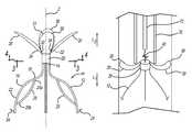
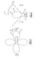
- the diameter of the hub 20is defined by the size of a bundle containing the filter struts 12 on the primary side or the loops 30 on the secondary side.
- the struts 12 and loops 30are both connected within the hub 20 and combine to define the diameter of the hub 20 , but the struts 12 and loops 30 do not necessarily overlap each other along the longitudinal axis Z.
- the diameter of the hub 20is determined by the point along the axis Z that has the greatest lateral buildup of struts 12 , loops 30 , or both.
- the number of struts 12 and loops 30can vary according to different embodiments, so the diameter of the hub 20 can change as the quantities of the struts 12 and loops 30 increase or decrease.
- the diameter of the hub 20corresponds to a cross-section that accommodates the larger one of the cross-sections of the strut or loop bundles.
- the anchor hooks 24 of the filter struts 12 and the apexes 36 of the loops 30are in engagement with the vessel wall.
- the anchor hooks 24 of the filter struts 12have anchored the filter 10 at the location of deployment in the vessel, preventing the filter 10 from moving with the blood flow through the vessel.
- the loops 30reduce the risk of tilting by keeping the hub 20 centered within the body vessel.
- the filter 10is supported by the plurality of struts 12 and the plurality of loops 30 that are spaced axially along the length of the filter 10 by offset Az ( FIG. 7 ).
- the filter 10With the filter 10 received within the sleeve 70 , the filter 10 , snaring mechanism 72 , and sleeve 70 can be retracted from the body.
Landscapes
- Health & Medical Sciences (AREA)
- Cardiology (AREA)
- Oral & Maxillofacial Surgery (AREA)
- Transplantation (AREA)
- Engineering & Computer Science (AREA)
- Biomedical Technology (AREA)
- Heart & Thoracic Surgery (AREA)
- Vascular Medicine (AREA)
- Life Sciences & Earth Sciences (AREA)
- Animal Behavior & Ethology (AREA)
- General Health & Medical Sciences (AREA)
- Public Health (AREA)
- Veterinary Medicine (AREA)
- Prostheses (AREA)
- Surgical Instruments (AREA)
Abstract
Description
Claims (15)
Priority Applications (1)
| Application Number | Priority Date | Filing Date | Title |
|---|---|---|---|
| US14/503,860US10010398B2 (en) | 2013-10-01 | 2014-10-01 | Filter device, system, and method |
Applications Claiming Priority (2)
| Application Number | Priority Date | Filing Date | Title |
|---|---|---|---|
| US201361885210P | 2013-10-01 | 2013-10-01 | |
| US14/503,860US10010398B2 (en) | 2013-10-01 | 2014-10-01 | Filter device, system, and method |
Publications (2)
| Publication Number | Publication Date |
|---|---|
| US20150094754A1 US20150094754A1 (en) | 2015-04-02 |
| US10010398B2true US10010398B2 (en) | 2018-07-03 |
Family
ID=52740873
Family Applications (1)
| Application Number | Title | Priority Date | Filing Date |
|---|---|---|---|
| US14/503,860Active2036-01-24US10010398B2 (en) | 2013-10-01 | 2014-10-01 | Filter device, system, and method |
Country Status (1)
| Country | Link |
|---|---|
| US (1) | US10010398B2 (en) |
Families Citing this family (2)
| Publication number | Priority date | Publication date | Assignee | Title |
|---|---|---|---|---|
| CN109998733A (en)* | 2019-04-19 | 2019-07-12 | 肖亮 | A kind of straight barrel type Metal Cutting sheath |
| CN113662704B (en)* | 2021-10-25 | 2022-02-15 | 深圳麦普奇医疗科技有限公司 | Vena cava filter catcher |
Citations (116)
| Publication number | Priority date | Publication date | Assignee | Title |
|---|---|---|---|---|
| US4425908A (en) | 1981-10-22 | 1984-01-17 | Beth Israel Hospital | Blood clot filter |
| US5133733A (en)* | 1989-11-28 | 1992-07-28 | William Cook Europe A/S | Collapsible filter for introduction in a blood vessel of a patient |
| US5324304A (en)* | 1992-06-18 | 1994-06-28 | William Cook Europe A/S | Introduction catheter set for a collapsible self-expandable implant |
| US5344427A (en)* | 1992-08-07 | 1994-09-06 | Celsa L.G. (Societe Anonyme) | Filter with triangular fingers |
| US5634942A (en)* | 1994-04-21 | 1997-06-03 | B. Braun Celsa | Assembly comprising a blood filter for temporary or definitive use and a device for implanting it |
| US5853420A (en)* | 1994-04-21 | 1998-12-29 | B. Braun Celsa | Assembly comprising a blood filter for temporary or definitive use and device for implanting it, corresponding filter and method of implanting such a filter |
| US6126673A (en) | 1993-10-01 | 2000-10-03 | Boston Scientific Corporation | Vena cava filter |
| US20020116024A1 (en)* | 2001-02-20 | 2002-08-22 | Uresil Corporation | Blood clot filtering system |
| US20020193828A1 (en)* | 2001-06-14 | 2002-12-19 | Cook Incorporated | Endovascular filter |
| US20030109897A1 (en)* | 2000-02-08 | 2003-06-12 | Scimed Life Systems, Inc. | Recoilable thrombosis filtering device and method |
| US20040073252A1 (en)* | 2001-02-20 | 2004-04-15 | Mark Goldberg | Blood clot filtering system |
| WO2004049953A1 (en) | 2002-12-02 | 2004-06-17 | Aquatic Remote Biopsy Pty Ltd | Fish biopsy device |
| US20040193209A1 (en)* | 2002-09-12 | 2004-09-30 | Dusan Pavcnik | Retrievable filter |
| US20040230220A1 (en)* | 2003-02-11 | 2004-11-18 | Cook Incorporated | Removable vena cava filter |
| US20050165442A1 (en)* | 2004-01-22 | 2005-07-28 | Thinnes John H.Jr. | Vein filter |
| WO2005072645A1 (en) | 2004-01-22 | 2005-08-11 | Rex Medical, L.P. | Vein filter |
| US20050222604A1 (en)* | 2004-03-31 | 2005-10-06 | Cook Incorporated | Self centering delivery catheter |
| WO2005102213A1 (en) | 2004-04-16 | 2005-11-03 | Cook, Inc. | Removable vena cava filter having primary struts for enhanced retrieval and delivery |
| WO2005102212A1 (en) | 2004-04-16 | 2005-11-03 | Cook, Inc. | Removable vena cava filter with anchoring feature for reduced trauma |
| WO2005102211A1 (en) | 2004-04-16 | 2005-11-03 | Cook, Inc. | Removable vena cava filter |
| WO2005102214A1 (en) | 2004-04-16 | 2005-11-03 | Cook, Inc. | Removable vena cava filter having inwardly positioned anchoring hooks in collapsed configuration |
| WO2005102210A1 (en) | 2004-04-16 | 2005-11-03 | Cook, Inc. | Removable vena cava filter for reduced trauma in collapsed configuration |
| US20050267514A1 (en) | 2004-04-16 | 2005-12-01 | Osborne Thomas A | Removable vena cava filter |
| US20050288704A1 (en)* | 2004-06-25 | 2005-12-29 | Angiodynamics, Inc. | Retrievable blood clot filter |
| US20060058832A1 (en)* | 2002-12-12 | 2006-03-16 | Andreas Melzer | Vessel filter |
| US20060069406A1 (en) | 2004-09-27 | 2006-03-30 | Per Hendriksen | Removable vena cava filter comprising struts having axial bends |
| US20060079928A1 (en)* | 2004-09-29 | 2006-04-13 | Angiodynamics, Inc. | Permanent blood clot filter with capability of being retrieved |
| US20060178695A1 (en)* | 2005-02-04 | 2006-08-10 | Decant Leonard J Jr | Vascular filter with sensing capability |
| US7128752B2 (en) | 2002-12-23 | 2006-10-31 | Syntheon, Llc | Emboli and thrombi filter device and method of using the same |
| US7150756B2 (en) | 1999-04-01 | 2006-12-19 | Scion Cardio-Vascular, Inc | Radiopaque locking frame, filter and flexible end |
| US7169166B2 (en) | 2000-05-30 | 2007-01-30 | Zuli Holdings, Ltd. | Active arterial embolization filter |
| US20070032816A1 (en)* | 2005-04-04 | 2007-02-08 | B.Braun Medical | Removable Filter Head |
| US7179275B2 (en) | 2001-06-18 | 2007-02-20 | Rex Medical, L.P. | Vein filter |
| US7179274B2 (en) | 2000-07-11 | 2007-02-20 | Rafael Medical Technologies Inc. | Intravascular filter |
| US7214237B2 (en) | 2001-03-12 | 2007-05-08 | Don Michael T Anthony | Vascular filter with improved strength and flexibility |
| US7226464B2 (en) | 2001-03-01 | 2007-06-05 | Scimed Life Systems, Inc. | Intravascular filter retrieval device having an actuatable dilator tip |
| US7229462B2 (en) | 1999-07-30 | 2007-06-12 | Angioguard, Inc. | Vascular filter system for carotid endarterectomy |
| US7229464B2 (en) | 2000-10-05 | 2007-06-12 | Scimed Life Systems, Inc. | Filter delivery and retrieval device |
| US7229463B2 (en) | 1999-07-30 | 2007-06-12 | Angioguard, Inc. | Vascular filter system for cardiopulmonary bypass |
| US7244267B2 (en) | 2001-06-29 | 2007-07-17 | Advanced Cardiovascular Systems, Inc. | Filter device for embolic protection systems |
| US20070173885A1 (en)* | 2006-01-20 | 2007-07-26 | Angiodynamics, Inc. | Retrievable blood clot filter |
| US20070198050A1 (en)* | 2006-02-22 | 2007-08-23 | Phase One Medica, Llc | Medical implant device |
| US7261731B2 (en) | 2000-10-20 | 2007-08-28 | Angiodynamics, Inc. | Convertible blood clot filter |
| US20070203520A1 (en)* | 1995-06-07 | 2007-08-30 | Dennis Griffin | Endovascular filter |
| US7306619B1 (en) | 2001-08-30 | 2007-12-11 | Advanced Cardiovascular Systems, Inc. | Self furling umbrella frame for carotid filter |
| US7314477B1 (en) | 1998-09-25 | 2008-01-01 | C.R. Bard Inc. | Removable embolus blood clot filter and filter delivery unit |
| US7323002B2 (en) | 2001-06-12 | 2008-01-29 | Cordis Corporation | Emboli extraction catheter and vascular filter system |
| US7399308B2 (en) | 1999-02-12 | 2008-07-15 | Cordis Corporation | Vascular filter system |
| US20080221609A1 (en)* | 2004-01-22 | 2008-09-11 | Mcguckin James F | Vein filter |
| US7479153B2 (en) | 2001-01-16 | 2009-01-20 | Boston Scientific Scimed, Inc. | Endovascular guidewire filter and methods of use |
| US7479151B2 (en) | 2002-08-05 | 2009-01-20 | Gardia Medical Ltd. | Embolism filter with self-deployable guidewire stop |
| US7481823B2 (en) | 2002-10-25 | 2009-01-27 | Boston Scientific Scimed, Inc. | Multiple membrane embolic protection filter |
| US7491215B2 (en) | 1999-05-07 | 2009-02-17 | Salviac Limited | Filter element for embolic protection device |
| US7491216B2 (en) | 1997-11-07 | 2009-02-17 | Salviac Limited | Filter element with retractable guidewire tip |
| US20090076585A1 (en)* | 2007-09-14 | 2009-03-19 | William Cook Europe | Device for loading a self-expandable prosthesis into a sheath |
| US7534251B2 (en) | 2003-02-11 | 2009-05-19 | Boston Scientific Scimed, Inc. | Retrievable IVC filter |
| US7575584B2 (en) | 2003-11-18 | 2009-08-18 | Boston Scientific Scimed, Inc. | Intravascular filter with bioabsorbable centering element |
| US7585309B2 (en) | 2002-05-16 | 2009-09-08 | Boston Scientific Scimed, Inc. | Aortic filter |
| US7618433B2 (en) | 1999-02-24 | 2009-11-17 | Boston Scientific Scimed, Inc. | Intravascular filter and method |
| US7648518B2 (en) | 2001-10-18 | 2010-01-19 | Incept Llc | Vascular embolic filter devices and methods of use therefor |
| US7686825B2 (en) | 2004-03-25 | 2010-03-30 | Hauser David L | Vascular filter device |
| US7704267B2 (en) | 2004-08-04 | 2010-04-27 | C. R. Bard, Inc. | Non-entangling vena cava filter |
| US7717935B2 (en) | 1999-11-15 | 2010-05-18 | Boston Scientific Scimed, Inc. | Guidewire filter and methods of use |
| US7722635B2 (en) | 2004-06-25 | 2010-05-25 | Angiodynamics, Inc. | Blood clot filter |
| US7731722B2 (en) | 2003-07-31 | 2010-06-08 | Vance Products Incorporated | Ureteral backstop filter and retrieval device |
| US7749246B2 (en) | 2004-09-27 | 2010-07-06 | Rex Medical, L.P. | Vein filter |
| US7758606B2 (en) | 2000-06-30 | 2010-07-20 | Medtronic, Inc. | Intravascular filter with debris entrapment mechanism |
| US7785343B2 (en) | 2005-01-03 | 2010-08-31 | Crux Biomedical, Inc. | Coated endoluminal filter |
| US7794472B2 (en) | 2004-08-11 | 2010-09-14 | Boston Scientific Scimed, Inc. | Single wire intravascular filter |
| US7803171B1 (en) | 2004-06-14 | 2010-09-28 | Uflacker Renan P | Retrievable inferior vena cava filter |
| US7806906B2 (en) | 2001-03-12 | 2010-10-05 | Don Michael T Anthony | Vascular filter with improved strength and flexibility |
| US7862578B2 (en) | 1999-08-03 | 2011-01-04 | Boston Scientific Scimed, Inc. | Guided filter with support wire and methods of use |
| US7875051B2 (en) | 2003-01-28 | 2011-01-25 | Boston Scientific Scimed, Inc. | Embolic protection filter having an improved filter frame |
| US7879065B2 (en) | 2004-03-19 | 2011-02-01 | Advanced Cardiovascular Systems, Inc. | Locking component for an embolic filter assembly |
| US7879063B2 (en) | 2000-01-13 | 2011-02-01 | Boston Scientific Cupertino Corp. | Deployable recoverable vascular filter and methods of use |
| US7887561B2 (en) | 2001-06-18 | 2011-02-15 | Rex Medical, L.P. | Multiple access vein filter |
| US7896898B2 (en) | 2003-07-30 | 2011-03-01 | Boston Scientific Scimed, Inc. | Self-centering blood clot filter |
| US7959645B2 (en) | 2004-11-03 | 2011-06-14 | Boston Scientific Scimed, Inc. | Retrievable vena cava filter |
| US7967838B2 (en) | 2005-05-12 | 2011-06-28 | C. R. Bard, Inc. | Removable embolus blood clot filter |
| US7993362B2 (en) | 2005-02-16 | 2011-08-09 | Boston Scientific Scimed, Inc. | Filter with positioning and retrieval devices and methods |
| US7998164B2 (en) | 2005-03-11 | 2011-08-16 | Boston Scientific Scimed, Inc. | Intravascular filter with centering member |
| US8025675B2 (en) | 2008-08-14 | 2011-09-27 | Cook Medical Technologies Llc | Temporary filter device |
| US8029529B1 (en) | 2005-01-19 | 2011-10-04 | C. R. Bard, Inc. | Retrievable filter |
| US8043323B2 (en) | 2006-10-18 | 2011-10-25 | Inspiremd Ltd. | In vivo filter assembly |
| US8048103B2 (en) | 2003-11-06 | 2011-11-01 | Boston Scientific Scimed, Inc. | Flattened tip filter wire design |
| US8052713B2 (en) | 1999-07-30 | 2011-11-08 | Incept, Llc | Vascular filter having articulation region and methods of use in the ascending aorta |
| US8057507B2 (en) | 2009-01-16 | 2011-11-15 | Novate Medical Limited | Vascular filter |
| US8062328B2 (en) | 2007-09-07 | 2011-11-22 | Merit Medical Systems, Inc. | Percutaneous permanent retrievable vascular filter |
| US8062324B2 (en) | 2006-05-08 | 2011-11-22 | S.M.T. Research And Development Ltd. | Device and method for vascular filter |
| US8062327B2 (en) | 2005-08-09 | 2011-11-22 | C. R. Bard, Inc. | Embolus blood clot filter and delivery system |
| US8070769B2 (en) | 2002-05-06 | 2011-12-06 | Boston Scientific Scimed, Inc. | Inverted embolic protection filter |
| US8080033B2 (en) | 2002-10-25 | 2011-12-20 | Boston Scientific Scimed, Inc. | Staged release of IVC filter legs |
| US8092485B2 (en) | 2006-12-12 | 2012-01-10 | C. R. Bard, Inc. | Recoverable inferior vena cava filter |
| US8092484B2 (en) | 2005-12-30 | 2012-01-10 | C.R. Bard, Inc. | Embolus blood clot filter with post delivery actuation |
| US8092486B2 (en) | 2002-03-12 | 2012-01-10 | Tyco Healthcare Group Lp | Everted filter device |
| US8100936B2 (en)* | 2004-01-22 | 2012-01-24 | Rex Medical, L.P. | Vein filter |
| US8133253B2 (en) | 2004-08-20 | 2012-03-13 | Cordis Corporation | Vascular filter with sleeve |
| US8152833B2 (en) | 2006-02-22 | 2012-04-10 | Tyco Healthcare Group Lp | Embolic protection systems having radiopaque filter mesh |
| US8162970B2 (en) | 2006-07-19 | 2012-04-24 | Novate Medical Limited | Vascular filter |
| US8162972B2 (en) | 2004-01-22 | 2012-04-24 | Rex Medical, Lp | Vein filter |
| EP2459119A1 (en) | 2009-07-29 | 2012-06-06 | C.R. Bard Inc. | Tubular filter |
| US8231649B2 (en) | 2004-01-20 | 2012-07-31 | Boston Scientific Scimed, Inc. | Retrievable blood clot filter with retractable anchoring members |
| US8231650B2 (en) | 2002-10-17 | 2012-07-31 | W. L. Gore & Associates, Inc. | Embolic filter frame having looped support strut elements |
| US8246648B2 (en) | 2008-11-10 | 2012-08-21 | Cook Medical Technologies Llc | Removable vena cava filter with improved leg |
| US8252017B2 (en) | 2005-10-18 | 2012-08-28 | Cook Medical Technologies Llc | Invertible filter for embolic protection |
| US8273099B2 (en) | 2000-01-26 | 2012-09-25 | Boston Scientific Scimed, Inc. | Thrombus filter with break-away anchor members |
| US8277479B2 (en) | 2006-06-26 | 2012-10-02 | Boston Scientific Scimed, Inc. | Self-opening filter with wire actuation |
| US8282668B2 (en) | 2001-06-18 | 2012-10-09 | Rex Medical, L.P. | Vein filter |
| US8317819B2 (en) | 1999-08-27 | 2012-11-27 | Covidien Lp | Slideable vascular filter |
| US8317818B2 (en) | 2005-12-30 | 2012-11-27 | C.R. Bard, Inc. | Removable blood clot filter with edge for cutting through the endothelium |
| US8333785B2 (en) | 2006-05-02 | 2012-12-18 | C. R. Bard, Inc. | IVC filter with translating hooks |
| EP2536461A2 (en) | 2010-02-18 | 2012-12-26 | Bio2Medical, Inc. | Vena cava filter catheter and method |
| US8353926B2 (en) | 2004-04-15 | 2013-01-15 | Cordis Corporation | Long-term retrievable medical filter |
| US8361103B2 (en) | 2003-02-07 | 2013-01-29 | Karla Weaver | Low profile IVC filter |
| US9034006B2 (en)* | 2005-12-01 | 2015-05-19 | Atritech, Inc. | Method and apparatus for retrieving an embolized implant |
| US20150305849A1 (en)* | 2012-11-21 | 2015-10-29 | B. Braun Medical Sas | Vein filter |
- 2014
- 2014-10-01USUS14/503,860patent/US10010398B2/enactiveActive
Patent Citations (152)
| Publication number | Priority date | Publication date | Assignee | Title |
|---|---|---|---|---|
| US4425908A (en) | 1981-10-22 | 1984-01-17 | Beth Israel Hospital | Blood clot filter |
| US5133733A (en)* | 1989-11-28 | 1992-07-28 | William Cook Europe A/S | Collapsible filter for introduction in a blood vessel of a patient |
| US5324304A (en)* | 1992-06-18 | 1994-06-28 | William Cook Europe A/S | Introduction catheter set for a collapsible self-expandable implant |
| US5344427A (en)* | 1992-08-07 | 1994-09-06 | Celsa L.G. (Societe Anonyme) | Filter with triangular fingers |
| US6126673A (en) | 1993-10-01 | 2000-10-03 | Boston Scientific Corporation | Vena cava filter |
| US6391045B1 (en) | 1993-10-01 | 2002-05-21 | Boston Scientific Corporation | Vena cava filter |
| US5634942A (en)* | 1994-04-21 | 1997-06-03 | B. Braun Celsa | Assembly comprising a blood filter for temporary or definitive use and a device for implanting it |
| US5853420A (en)* | 1994-04-21 | 1998-12-29 | B. Braun Celsa | Assembly comprising a blood filter for temporary or definitive use and device for implanting it, corresponding filter and method of implanting such a filter |
| US20070203520A1 (en)* | 1995-06-07 | 2007-08-30 | Dennis Griffin | Endovascular filter |
| US8328842B2 (en) | 1997-11-07 | 2012-12-11 | Salviac Limited | Filter element with retractable guidewire tip |
| US7901427B2 (en) | 1997-11-07 | 2011-03-08 | Salviac Limited | Filter element with retractable guidewire tip |
| US7491216B2 (en) | 1997-11-07 | 2009-02-17 | Salviac Limited | Filter element with retractable guidewire tip |
| US8133251B2 (en) | 1998-09-25 | 2012-03-13 | C.R. Bard, Inc. | Removeable embolus blood clot filter and filter delivery unit |
| US7314477B1 (en) | 1998-09-25 | 2008-01-01 | C.R. Bard Inc. | Removable embolus blood clot filter and filter delivery unit |
| US7399308B2 (en) | 1999-02-12 | 2008-07-15 | Cordis Corporation | Vascular filter system |
| US8303618B2 (en) | 1999-02-24 | 2012-11-06 | Boston Scientific Scimed, Inc. | Intravascular filter and method |
| US7618433B2 (en) | 1999-02-24 | 2009-11-17 | Boston Scientific Scimed, Inc. | Intravascular filter and method |
| US7150756B2 (en) | 1999-04-01 | 2006-12-19 | Scion Cardio-Vascular, Inc | Radiopaque locking frame, filter and flexible end |
| US7491215B2 (en) | 1999-05-07 | 2009-02-17 | Salviac Limited | Filter element for embolic protection device |
| US8052713B2 (en) | 1999-07-30 | 2011-11-08 | Incept, Llc | Vascular filter having articulation region and methods of use in the ascending aorta |
| US7229463B2 (en) | 1999-07-30 | 2007-06-12 | Angioguard, Inc. | Vascular filter system for cardiopulmonary bypass |
| US7229462B2 (en) | 1999-07-30 | 2007-06-12 | Angioguard, Inc. | Vascular filter system for carotid endarterectomy |
| US8231651B2 (en) | 1999-08-03 | 2012-07-31 | Boston Scientific Scimed, Inc. | Guided filter with support wire and methods of use |
| US7862578B2 (en) | 1999-08-03 | 2011-01-04 | Boston Scientific Scimed, Inc. | Guided filter with support wire and methods of use |
| US8317819B2 (en) | 1999-08-27 | 2012-11-27 | Covidien Lp | Slideable vascular filter |
| US7931665B2 (en) | 1999-11-15 | 2011-04-26 | Boston Scientific Scimed, Inc. | Guidewire filter and methods of use |
| US7717935B2 (en) | 1999-11-15 | 2010-05-18 | Boston Scientific Scimed, Inc. | Guidewire filter and methods of use |
| US7879063B2 (en) | 2000-01-13 | 2011-02-01 | Boston Scientific Cupertino Corp. | Deployable recoverable vascular filter and methods of use |
| US8273099B2 (en) | 2000-01-26 | 2012-09-25 | Boston Scientific Scimed, Inc. | Thrombus filter with break-away anchor members |
| US20030109897A1 (en)* | 2000-02-08 | 2003-06-12 | Scimed Life Systems, Inc. | Recoilable thrombosis filtering device and method |
| US20050131452A1 (en)* | 2000-02-08 | 2005-06-16 | Walak Steven E. | Recoilable thrombosis filtering device and method |
| US6872217B2 (en)* | 2000-02-08 | 2005-03-29 | Scimed Life Systems, Inc. | Recoilable thrombosis filtering device and method |
| US7169166B2 (en) | 2000-05-30 | 2007-01-30 | Zuli Holdings, Ltd. | Active arterial embolization filter |
| US7758606B2 (en) | 2000-06-30 | 2010-07-20 | Medtronic, Inc. | Intravascular filter with debris entrapment mechanism |
| US8092487B2 (en) | 2000-06-30 | 2012-01-10 | Medtronic, Inc. | Intravascular filter with debris entrapment mechanism |
| US7179274B2 (en) | 2000-07-11 | 2007-02-20 | Rafael Medical Technologies Inc. | Intravascular filter |
| US7229464B2 (en) | 2000-10-05 | 2007-06-12 | Scimed Life Systems, Inc. | Filter delivery and retrieval device |
| US7261731B2 (en) | 2000-10-20 | 2007-08-28 | Angiodynamics, Inc. | Convertible blood clot filter |
| US7479153B2 (en) | 2001-01-16 | 2009-01-20 | Boston Scientific Scimed, Inc. | Endovascular guidewire filter and methods of use |
| US20040073252A1 (en)* | 2001-02-20 | 2004-04-15 | Mark Goldberg | Blood clot filtering system |
| US20020116024A1 (en)* | 2001-02-20 | 2002-08-22 | Uresil Corporation | Blood clot filtering system |
| US7226464B2 (en) | 2001-03-01 | 2007-06-05 | Scimed Life Systems, Inc. | Intravascular filter retrieval device having an actuatable dilator tip |
| US7806906B2 (en) | 2001-03-12 | 2010-10-05 | Don Michael T Anthony | Vascular filter with improved strength and flexibility |
| US7214237B2 (en) | 2001-03-12 | 2007-05-08 | Don Michael T Anthony | Vascular filter with improved strength and flexibility |
| US7323002B2 (en) | 2001-06-12 | 2008-01-29 | Cordis Corporation | Emboli extraction catheter and vascular filter system |
| US20020193828A1 (en)* | 2001-06-14 | 2002-12-19 | Cook Incorporated | Endovascular filter |
| US7179275B2 (en) | 2001-06-18 | 2007-02-20 | Rex Medical, L.P. | Vein filter |
| US8282668B2 (en) | 2001-06-18 | 2012-10-09 | Rex Medical, L.P. | Vein filter |
| US7887561B2 (en) | 2001-06-18 | 2011-02-15 | Rex Medical, L.P. | Multiple access vein filter |
| US7244267B2 (en) | 2001-06-29 | 2007-07-17 | Advanced Cardiovascular Systems, Inc. | Filter device for embolic protection systems |
| US7959646B2 (en) | 2001-06-29 | 2011-06-14 | Abbott Cardiovascular Systems Inc. | Filter device for embolic protection systems |
| US7306619B1 (en) | 2001-08-30 | 2007-12-11 | Advanced Cardiovascular Systems, Inc. | Self furling umbrella frame for carotid filter |
| US7648518B2 (en) | 2001-10-18 | 2010-01-19 | Incept Llc | Vascular embolic filter devices and methods of use therefor |
| US8092486B2 (en) | 2002-03-12 | 2012-01-10 | Tyco Healthcare Group Lp | Everted filter device |
| US8070769B2 (en) | 2002-05-06 | 2011-12-06 | Boston Scientific Scimed, Inc. | Inverted embolic protection filter |
| US7585309B2 (en) | 2002-05-16 | 2009-09-08 | Boston Scientific Scimed, Inc. | Aortic filter |
| US7479151B2 (en) | 2002-08-05 | 2009-01-20 | Gardia Medical Ltd. | Embolism filter with self-deployable guidewire stop |
| US20040193209A1 (en)* | 2002-09-12 | 2004-09-30 | Dusan Pavcnik | Retrievable filter |
| US8231650B2 (en) | 2002-10-17 | 2012-07-31 | W. L. Gore & Associates, Inc. | Embolic filter frame having looped support strut elements |
| US8080033B2 (en) | 2002-10-25 | 2011-12-20 | Boston Scientific Scimed, Inc. | Staged release of IVC filter legs |
| US7481823B2 (en) | 2002-10-25 | 2009-01-27 | Boston Scientific Scimed, Inc. | Multiple membrane embolic protection filter |
| WO2004049953A1 (en) | 2002-12-02 | 2004-06-17 | Aquatic Remote Biopsy Pty Ltd | Fish biopsy device |
| US20060058832A1 (en)* | 2002-12-12 | 2006-03-16 | Andreas Melzer | Vessel filter |
| US7766932B2 (en) | 2002-12-12 | 2010-08-03 | Amris Patente Gmbh | Vessel filter |
| US7128752B2 (en) | 2002-12-23 | 2006-10-31 | Syntheon, Llc | Emboli and thrombi filter device and method of using the same |
| US7972355B2 (en) | 2002-12-23 | 2011-07-05 | Boston Scientific Scimed, Inc. | Emboli and thrombi filter device and method of using the same |
| US7875051B2 (en) | 2003-01-28 | 2011-01-25 | Boston Scientific Scimed, Inc. | Embolic protection filter having an improved filter frame |
| US8361103B2 (en) | 2003-02-07 | 2013-01-29 | Karla Weaver | Low profile IVC filter |
| US7534251B2 (en) | 2003-02-11 | 2009-05-19 | Boston Scientific Scimed, Inc. | Retrievable IVC filter |
| US7763045B2 (en) | 2003-02-11 | 2010-07-27 | Cook Incorporated | Removable vena cava filter |
| US20040230220A1 (en)* | 2003-02-11 | 2004-11-18 | Cook Incorporated | Removable vena cava filter |
| US8246650B2 (en) | 2003-02-11 | 2012-08-21 | Cook Medical Technologies Llc | Removable vena cava filter |
| US7896898B2 (en) | 2003-07-30 | 2011-03-01 | Boston Scientific Scimed, Inc. | Self-centering blood clot filter |
| US7731722B2 (en) | 2003-07-31 | 2010-06-08 | Vance Products Incorporated | Ureteral backstop filter and retrieval device |
| US8048103B2 (en) | 2003-11-06 | 2011-11-01 | Boston Scientific Scimed, Inc. | Flattened tip filter wire design |
| US7575584B2 (en) | 2003-11-18 | 2009-08-18 | Boston Scientific Scimed, Inc. | Intravascular filter with bioabsorbable centering element |
| US8231649B2 (en) | 2004-01-20 | 2012-07-31 | Boston Scientific Scimed, Inc. | Retrievable blood clot filter with retractable anchoring members |
| US7704266B2 (en)* | 2004-01-22 | 2010-04-27 | Rex Medical, L.P. | Vein filter |
| US8211140B2 (en) | 2004-01-22 | 2012-07-03 | Rex Medical, L.P. | Vein filter |
| WO2005072645A1 (en) | 2004-01-22 | 2005-08-11 | Rex Medical, L.P. | Vein filter |
| US7338512B2 (en) | 2004-01-22 | 2008-03-04 | Rex Medical, L.P. | Vein filter |
| US20050165442A1 (en)* | 2004-01-22 | 2005-07-28 | Thinnes John H.Jr. | Vein filter |
| US8162972B2 (en) | 2004-01-22 | 2012-04-24 | Rex Medical, Lp | Vein filter |
| US8062326B2 (en)* | 2004-01-22 | 2011-11-22 | Rex Medical, L.P. | Vein filter |
| US20080221609A1 (en)* | 2004-01-22 | 2008-09-11 | Mcguckin James F | Vein filter |
| US8100936B2 (en)* | 2004-01-22 | 2012-01-24 | Rex Medical, L.P. | Vein filter |
| US7879065B2 (en) | 2004-03-19 | 2011-02-01 | Advanced Cardiovascular Systems, Inc. | Locking component for an embolic filter assembly |
| US7686825B2 (en) | 2004-03-25 | 2010-03-30 | Hauser David L | Vascular filter device |
| US20050222604A1 (en)* | 2004-03-31 | 2005-10-06 | Cook Incorporated | Self centering delivery catheter |
| US8353926B2 (en) | 2004-04-15 | 2013-01-15 | Cordis Corporation | Long-term retrievable medical filter |
| US7625390B2 (en) | 2004-04-16 | 2009-12-01 | Cook Incorporated | Removable vena cava filter |
| WO2005102213A1 (en) | 2004-04-16 | 2005-11-03 | Cook, Inc. | Removable vena cava filter having primary struts for enhanced retrieval and delivery |
| US20050267514A1 (en) | 2004-04-16 | 2005-12-01 | Osborne Thomas A | Removable vena cava filter |
| US8246651B2 (en) | 2004-04-16 | 2012-08-21 | Cook Medical Technologies Llc | Removable vena cava filter for reduced trauma in collapsed configuration |
| US20050267513A1 (en) | 2004-04-16 | 2005-12-01 | Osborne Thomas A | Removable vena cava filter having primary struts for enhanced retrieval and delivery |
| WO2005102211A1 (en) | 2004-04-16 | 2005-11-03 | Cook, Inc. | Removable vena cava filter |
| US20050251199A1 (en)* | 2004-04-16 | 2005-11-10 | Osborne Thomas A | Removable vena cava filter with anchoring feature for reduced trauma |
| WO2005102212A1 (en) | 2004-04-16 | 2005-11-03 | Cook, Inc. | Removable vena cava filter with anchoring feature for reduced trauma |
| US7699867B2 (en) | 2004-04-16 | 2010-04-20 | Cook Incorporated | Removable vena cava filter for reduced trauma in collapsed configuration |
| WO2005102210A1 (en) | 2004-04-16 | 2005-11-03 | Cook, Inc. | Removable vena cava filter for reduced trauma in collapsed configuration |
| US8043322B2 (en) | 2004-04-16 | 2011-10-25 | Cook Medical Technologies Llc | Removable vena cava filter having inwardly positioned anchoring hooks in collapsed configuration |
| WO2005102214A1 (en) | 2004-04-16 | 2005-11-03 | Cook, Inc. | Removable vena cava filter having inwardly positioned anchoring hooks in collapsed configuration |
| US7972353B2 (en) | 2004-04-16 | 2011-07-05 | Cook Medical Technologies Llc | Removable vena cava filter with anchoring feature for reduced trauma |
| US8105349B2 (en) | 2004-04-16 | 2012-01-31 | Cook Medical Technologies Llc | Removable vena cava filter having primary struts for enhanced retrieval and delivery |
| US7803171B1 (en) | 2004-06-14 | 2010-09-28 | Uflacker Renan P | Retrievable inferior vena cava filter |
| US20050288704A1 (en)* | 2004-06-25 | 2005-12-29 | Angiodynamics, Inc. | Retrievable blood clot filter |
| US8118828B2 (en) | 2004-06-25 | 2012-02-21 | Angiodynamics, Inc. | Retrievable blood clot filter and method of retrieving |
| US7722635B2 (en) | 2004-06-25 | 2010-05-25 | Angiodynamics, Inc. | Blood clot filter |
| US7544202B2 (en) | 2004-06-25 | 2009-06-09 | Angiodynamics, Inc. | Retrievable blood clot filter |
| US7704267B2 (en) | 2004-08-04 | 2010-04-27 | C. R. Bard, Inc. | Non-entangling vena cava filter |
| US7794472B2 (en) | 2004-08-11 | 2010-09-14 | Boston Scientific Scimed, Inc. | Single wire intravascular filter |
| US8133253B2 (en) | 2004-08-20 | 2012-03-13 | Cordis Corporation | Vascular filter with sleeve |
| US8167901B2 (en) | 2004-09-27 | 2012-05-01 | Cook Medical Technologies Llc | Removable vena cava filter comprising struts having axial bends |
| WO2006036867A1 (en) | 2004-09-27 | 2006-04-06 | Cook, Inc. | Removable vena cava filter comprising struts having axial beds |
| US7909847B2 (en) | 2004-09-27 | 2011-03-22 | Rex Medical, L.P. | Vein filter |
| US7749246B2 (en) | 2004-09-27 | 2010-07-06 | Rex Medical, L.P. | Vein filter |
| US20060069406A1 (en) | 2004-09-27 | 2006-03-30 | Per Hendriksen | Removable vena cava filter comprising struts having axial bends |
| US7279000B2 (en) | 2004-09-29 | 2007-10-09 | Angiodynamics Inc | Permanent blood clot filter with capability of being retrieved |
| US20060079928A1 (en)* | 2004-09-29 | 2006-04-13 | Angiodynamics, Inc. | Permanent blood clot filter with capability of being retrieved |
| US7959645B2 (en) | 2004-11-03 | 2011-06-14 | Boston Scientific Scimed, Inc. | Retrievable vena cava filter |
| US7785343B2 (en) | 2005-01-03 | 2010-08-31 | Crux Biomedical, Inc. | Coated endoluminal filter |
| US7854747B2 (en) | 2005-01-03 | 2010-12-21 | Crux Biomedical, Inc. | Endoluminal filter |
| US8226679B2 (en) | 2005-01-03 | 2012-07-24 | Crux Biomedical, Inc. | Spiral shaped filter |
| US8029529B1 (en) | 2005-01-19 | 2011-10-04 | C. R. Bard, Inc. | Retrievable filter |
| US8267954B2 (en) | 2005-02-04 | 2012-09-18 | C. R. Bard, Inc. | Vascular filter with sensing capability |
| US20060178695A1 (en)* | 2005-02-04 | 2006-08-10 | Decant Leonard J Jr | Vascular filter with sensing capability |
| US7993362B2 (en) | 2005-02-16 | 2011-08-09 | Boston Scientific Scimed, Inc. | Filter with positioning and retrieval devices and methods |
| US7998164B2 (en) | 2005-03-11 | 2011-08-16 | Boston Scientific Scimed, Inc. | Intravascular filter with centering member |
| US20070032816A1 (en)* | 2005-04-04 | 2007-02-08 | B.Braun Medical | Removable Filter Head |
| US7967838B2 (en) | 2005-05-12 | 2011-06-28 | C. R. Bard, Inc. | Removable embolus blood clot filter |
| US8062327B2 (en) | 2005-08-09 | 2011-11-22 | C. R. Bard, Inc. | Embolus blood clot filter and delivery system |
| US8252017B2 (en) | 2005-10-18 | 2012-08-28 | Cook Medical Technologies Llc | Invertible filter for embolic protection |
| US9034006B2 (en)* | 2005-12-01 | 2015-05-19 | Atritech, Inc. | Method and apparatus for retrieving an embolized implant |
| US8092484B2 (en) | 2005-12-30 | 2012-01-10 | C.R. Bard, Inc. | Embolus blood clot filter with post delivery actuation |
| US8317818B2 (en) | 2005-12-30 | 2012-11-27 | C.R. Bard, Inc. | Removable blood clot filter with edge for cutting through the endothelium |
| US20070173885A1 (en)* | 2006-01-20 | 2007-07-26 | Angiodynamics, Inc. | Retrievable blood clot filter |
| US8152833B2 (en) | 2006-02-22 | 2012-04-10 | Tyco Healthcare Group Lp | Embolic protection systems having radiopaque filter mesh |
| US20070198050A1 (en)* | 2006-02-22 | 2007-08-23 | Phase One Medica, Llc | Medical implant device |
| US8333785B2 (en) | 2006-05-02 | 2012-12-18 | C. R. Bard, Inc. | IVC filter with translating hooks |
| US8062324B2 (en) | 2006-05-08 | 2011-11-22 | S.M.T. Research And Development Ltd. | Device and method for vascular filter |
| US8277479B2 (en) | 2006-06-26 | 2012-10-02 | Boston Scientific Scimed, Inc. | Self-opening filter with wire actuation |
| US8162970B2 (en) | 2006-07-19 | 2012-04-24 | Novate Medical Limited | Vascular filter |
| US8043323B2 (en) | 2006-10-18 | 2011-10-25 | Inspiremd Ltd. | In vivo filter assembly |
| US8092485B2 (en) | 2006-12-12 | 2012-01-10 | C. R. Bard, Inc. | Recoverable inferior vena cava filter |
| US8062328B2 (en) | 2007-09-07 | 2011-11-22 | Merit Medical Systems, Inc. | Percutaneous permanent retrievable vascular filter |
| US20090076585A1 (en)* | 2007-09-14 | 2009-03-19 | William Cook Europe | Device for loading a self-expandable prosthesis into a sheath |
| US8025675B2 (en) | 2008-08-14 | 2011-09-27 | Cook Medical Technologies Llc | Temporary filter device |
| US8246648B2 (en) | 2008-11-10 | 2012-08-21 | Cook Medical Technologies Llc | Removable vena cava filter with improved leg |
| US8057507B2 (en) | 2009-01-16 | 2011-11-15 | Novate Medical Limited | Vascular filter |
| EP2459119A1 (en) | 2009-07-29 | 2012-06-06 | C.R. Bard Inc. | Tubular filter |
| EP2536461A2 (en) | 2010-02-18 | 2012-12-26 | Bio2Medical, Inc. | Vena cava filter catheter and method |
| US20150305849A1 (en)* | 2012-11-21 | 2015-10-29 | B. Braun Medical Sas | Vein filter |
Also Published As
| Publication number | Publication date |
|---|---|
| US20150094754A1 (en) | 2015-04-02 |
Similar Documents
| Publication | Publication Date | Title |
|---|---|---|
| US9980803B2 (en) | Medical device retrieval system and method | |
| US6214025B1 (en) | Self-centering, self-expanding and retrievable vena cava filter | |
| US6273900B1 (en) | Blood clot filtering | |
| US8043322B2 (en) | Removable vena cava filter having inwardly positioned anchoring hooks in collapsed configuration | |
| JP4898986B2 (en) | Removable vena cava filter with anchor shape to reduce damage | |
| US7625390B2 (en) | Removable vena cava filter | |
| US8246651B2 (en) | Removable vena cava filter for reduced trauma in collapsed configuration | |
| JP4898988B2 (en) | Retrievable vena cava filter with primary struts to enhance retrieval and delivery performance | |
| US20060100660A1 (en) | Blood clot filter configured for a wire guide | |
| US20060015137A1 (en) | Retrievable intravascular filter with bendable anchoring members | |
| JP2007532267A5 (en) | ||
| JP2007532270A5 (en) | ||
| EP2777602B1 (en) | Removable vena cava filter having primary and secondary struts | |
| US9788932B2 (en) | Vascular filter | |
| US10010398B2 (en) | Filter device, system, and method | |
| US9308073B2 (en) | Vena cava filter with dual retrieval | |
| AU2005235302B2 (en) | Removable vena cava filter |
Legal Events
| Date | Code | Title | Description |
|---|---|---|---|
| AS | Assignment | Owner name:COOK INCORPORATED, INDIANA Free format text:ASSIGNMENT OF ASSIGNORS INTEREST;ASSIGNORS:TRELOAR, THOMAS ADAM;COOK, LESLIE;STRADER, JOHN TYLER;AND OTHERS;SIGNING DATES FROM 20131102 TO 20131115;REEL/FRAME:034057/0261 Owner name:COOK MEDICAL TECHNOLOGIES LLC, INDIANA Free format text:ASSIGNMENT OF ASSIGNORS INTEREST;ASSIGNOR:COOK INCORPORATED;REEL/FRAME:034057/0385 Effective date:20131121 Owner name:COOK MEDICAL TECHNOLOGIES LLC, INDIANA Free format text:ASSIGNMENT OF ASSIGNORS INTEREST;ASSIGNOR:SABIN CORPORATION;REEL/FRAME:034057/0586 Effective date:20131028 Owner name:SABIN CORPORATION, INDIANA Free format text:ASSIGNMENT OF ASSIGNORS INTEREST;ASSIGNOR:PATTERSON, DON;REEL/FRAME:034057/0537 Effective date:20131028 | |
| STCF | Information on status: patent grant | Free format text:PATENTED CASE | |
| MAFP | Maintenance fee payment | Free format text:PAYMENT OF MAINTENANCE FEE, 4TH YEAR, LARGE ENTITY (ORIGINAL EVENT CODE: M1551); ENTITY STATUS OF PATENT OWNER: LARGE ENTITY Year of fee payment:4 | |
| AS | Assignment | Owner name:WILMINGTON TRUST, NATIONAL ASSOCIATION, AS COLLATERAL AGENT, DELAWARE Free format text:SECURITY INTEREST;ASSIGNOR:COOK MEDICAL TECHNOLOGIES LLC;REEL/FRAME:066700/0277 Effective date:20240227 |