US10010394B2 - Pelvic floor treatments and related tools and implants - Google Patents
Pelvic floor treatments and related tools and implantsDownload PDFInfo
- Publication number
- US10010394B2 US10010394B2US15/149,692US201615149692AUS10010394B2US 10010394 B2US10010394 B2US 10010394B2US 201615149692 AUS201615149692 AUS 201615149692AUS 10010394 B2US10010394 B2US 10010394B2
- Authority
- US
- United States
- Prior art keywords
- sheath
- shaft
- tissue
- distal
- proximal
- Prior art date
- Legal status (The legal status is an assumption and is not a legal conclusion. Google has not performed a legal analysis and makes no representation as to the accuracy of the status listed.)
- Expired - Fee Related
Links
Images


Classifications
- A—HUMAN NECESSITIES
- A61—MEDICAL OR VETERINARY SCIENCE; HYGIENE
- A61F—FILTERS IMPLANTABLE INTO BLOOD VESSELS; PROSTHESES; DEVICES PROVIDING PATENCY TO, OR PREVENTING COLLAPSING OF, TUBULAR STRUCTURES OF THE BODY, e.g. STENTS; ORTHOPAEDIC, NURSING OR CONTRACEPTIVE DEVICES; FOMENTATION; TREATMENT OR PROTECTION OF EYES OR EARS; BANDAGES, DRESSINGS OR ABSORBENT PADS; FIRST-AID KITS
- A61F2/00—Filters implantable into blood vessels; Prostheses, i.e. artificial substitutes or replacements for parts of the body; Appliances for connecting them with the body; Devices providing patency to, or preventing collapsing of, tubular structures of the body, e.g. stents
- A61F2/0063—Implantable repair or support meshes, e.g. hernia meshes
- A—HUMAN NECESSITIES
- A61—MEDICAL OR VETERINARY SCIENCE; HYGIENE
- A61B—DIAGNOSIS; SURGERY; IDENTIFICATION
- A61B17/00—Surgical instruments, devices or methods
- A61B17/00234—Surgical instruments, devices or methods for minimally invasive surgery
- A—HUMAN NECESSITIES
- A61—MEDICAL OR VETERINARY SCIENCE; HYGIENE
- A61B—DIAGNOSIS; SURGERY; IDENTIFICATION
- A61B17/00—Surgical instruments, devices or methods
- A61B17/04—Surgical instruments, devices or methods for suturing wounds; Holders or packages for needles or suture materials
- A61B17/0401—Suture anchors, buttons or pledgets, i.e. means for attaching sutures to bone, cartilage or soft tissue; Instruments for applying or removing suture anchors
- A—HUMAN NECESSITIES
- A61—MEDICAL OR VETERINARY SCIENCE; HYGIENE
- A61F—FILTERS IMPLANTABLE INTO BLOOD VESSELS; PROSTHESES; DEVICES PROVIDING PATENCY TO, OR PREVENTING COLLAPSING OF, TUBULAR STRUCTURES OF THE BODY, e.g. STENTS; ORTHOPAEDIC, NURSING OR CONTRACEPTIVE DEVICES; FOMENTATION; TREATMENT OR PROTECTION OF EYES OR EARS; BANDAGES, DRESSINGS OR ABSORBENT PADS; FIRST-AID KITS
- A61F2/00—Filters implantable into blood vessels; Prostheses, i.e. artificial substitutes or replacements for parts of the body; Appliances for connecting them with the body; Devices providing patency to, or preventing collapsing of, tubular structures of the body, e.g. stents
- A61F2/0004—Closure means for urethra or rectum, i.e. anti-incontinence devices or support slings against pelvic prolapse
- A61F2/0031—Closure means for urethra or rectum, i.e. anti-incontinence devices or support slings against pelvic prolapse for constricting the lumen; Support slings for the urethra
- A61F2/0036—Closure means for urethra or rectum, i.e. anti-incontinence devices or support slings against pelvic prolapse for constricting the lumen; Support slings for the urethra implantable
- A61F2/0045—Support slings
- A—HUMAN NECESSITIES
- A61—MEDICAL OR VETERINARY SCIENCE; HYGIENE
- A61B—DIAGNOSIS; SURGERY; IDENTIFICATION
- A61B17/00—Surgical instruments, devices or methods
- A61B17/34—Trocars; Puncturing needles
- A61B17/3468—Trocars; Puncturing needles for implanting or removing devices, e.g. prostheses, implants, seeds, wires
- A—HUMAN NECESSITIES
- A61—MEDICAL OR VETERINARY SCIENCE; HYGIENE
- A61B—DIAGNOSIS; SURGERY; IDENTIFICATION
- A61B17/00—Surgical instruments, devices or methods
- A61B2017/00743—Type of operation; Specification of treatment sites
- A61B2017/00805—Treatment of female stress urinary incontinence
- A—HUMAN NECESSITIES
- A61—MEDICAL OR VETERINARY SCIENCE; HYGIENE
- A61B—DIAGNOSIS; SURGERY; IDENTIFICATION
- A61B17/00—Surgical instruments, devices or methods
- A61B17/04—Surgical instruments, devices or methods for suturing wounds; Holders or packages for needles or suture materials
- A61B17/0401—Suture anchors, buttons or pledgets, i.e. means for attaching sutures to bone, cartilage or soft tissue; Instruments for applying or removing suture anchors
- A61B2017/0409—Instruments for applying suture anchors
- A—HUMAN NECESSITIES
- A61—MEDICAL OR VETERINARY SCIENCE; HYGIENE
- A61B—DIAGNOSIS; SURGERY; IDENTIFICATION
- A61B17/00—Surgical instruments, devices or methods
- A61B17/04—Surgical instruments, devices or methods for suturing wounds; Holders or packages for needles or suture materials
- A61B17/0401—Suture anchors, buttons or pledgets, i.e. means for attaching sutures to bone, cartilage or soft tissue; Instruments for applying or removing suture anchors
- A61B2017/0412—Suture anchors, buttons or pledgets, i.e. means for attaching sutures to bone, cartilage or soft tissue; Instruments for applying or removing suture anchors having anchoring barbs or pins extending outwardly from suture anchor body
- A—HUMAN NECESSITIES
- A61—MEDICAL OR VETERINARY SCIENCE; HYGIENE
- A61B—DIAGNOSIS; SURGERY; IDENTIFICATION
- A61B17/00—Surgical instruments, devices or methods
- A61B17/04—Surgical instruments, devices or methods for suturing wounds; Holders or packages for needles or suture materials
- A61B17/0401—Suture anchors, buttons or pledgets, i.e. means for attaching sutures to bone, cartilage or soft tissue; Instruments for applying or removing suture anchors
- A61B2017/0427—Suture anchors, buttons or pledgets, i.e. means for attaching sutures to bone, cartilage or soft tissue; Instruments for applying or removing suture anchors having anchoring barbs or pins extending outwardly from the anchor body
- A—HUMAN NECESSITIES
- A61—MEDICAL OR VETERINARY SCIENCE; HYGIENE
- A61B—DIAGNOSIS; SURGERY; IDENTIFICATION
- A61B17/00—Surgical instruments, devices or methods
- A61B17/04—Surgical instruments, devices or methods for suturing wounds; Holders or packages for needles or suture materials
- A61B17/0401—Suture anchors, buttons or pledgets, i.e. means for attaching sutures to bone, cartilage or soft tissue; Instruments for applying or removing suture anchors
- A61B2017/0464—Suture anchors, buttons or pledgets, i.e. means for attaching sutures to bone, cartilage or soft tissue; Instruments for applying or removing suture anchors for soft tissue
- A—HUMAN NECESSITIES
- A61—MEDICAL OR VETERINARY SCIENCE; HYGIENE
- A61B—DIAGNOSIS; SURGERY; IDENTIFICATION
- A61B90/00—Instruments, implements or accessories specially adapted for surgery or diagnosis and not covered by any of the groups A61B1/00 - A61B50/00, e.g. for luxation treatment or for protecting wound edges
- A61B90/08—Accessories or related features not otherwise provided for
- A61B2090/0801—Prevention of accidental cutting or pricking
- A61B2090/08021—Prevention of accidental cutting or pricking of the patient or his organs
- A—HUMAN NECESSITIES
- A61—MEDICAL OR VETERINARY SCIENCE; HYGIENE
- A61F—FILTERS IMPLANTABLE INTO BLOOD VESSELS; PROSTHESES; DEVICES PROVIDING PATENCY TO, OR PREVENTING COLLAPSING OF, TUBULAR STRUCTURES OF THE BODY, e.g. STENTS; ORTHOPAEDIC, NURSING OR CONTRACEPTIVE DEVICES; FOMENTATION; TREATMENT OR PROTECTION OF EYES OR EARS; BANDAGES, DRESSINGS OR ABSORBENT PADS; FIRST-AID KITS
- A61F2/00—Filters implantable into blood vessels; Prostheses, i.e. artificial substitutes or replacements for parts of the body; Appliances for connecting them with the body; Devices providing patency to, or preventing collapsing of, tubular structures of the body, e.g. stents
- A61F2/0063—Implantable repair or support meshes, e.g. hernia meshes
- A61F2002/0072—Delivery tools therefor
Definitions
- the inventionrelates to apparatus and methods for implanting a surgical implant, e.g., a pelvic implant for treating pelvic conditions.
- the methodsinclude an implant to support tissue.
- conditionsinclude conditions of the female or male anatomy, and specifically include treatments of pelvic conditions such as female or male urinary and fecal incontinence, and treatment of female vaginal prolapse conditions including enterocele, rectocele, cystocele, vault prolapse, conditions of the pelvic floor, and any of these conditions in combination.
- Biological implants for supporting tissue, to treat medical conditionsare generally known and used to treat various ailments.
- Various conditions of female and male pelvic anatomycan be treated by supportive implants.
- pelvic prolapse conditionsincluding vaginal prolapse, can be caused by the weakening or breakdown of various parts of the pelvic support system such as the pelvic floor or tissue surrounding the vagina.
- weakened tissuescan result in fecal incontinence, urinary incontinence, and levator avulsion and other conditions of the pelvic floor.
- structuressuch as the uterus, rectum, bladder, urethra, small intestine, levator and muscle of the pelvic floor, and vagina, may begin to fall out of their normal positions.
- Pelvic conditionssuch as these, as well as other conditions of biologic tissue, can be treated by placement of synthetic or biological implants to support weakened or affected tissues.
- the inventioninvolves implants, systems, kits, and method, for placing a surgical implant for supporting tissue.
- Embodiments of the inventioninvolve the use of a tool (sometimes referred to as an “insertion tool” or “introducer tool”) that includes a shaft and a sheath that engages the shaft in a “covered” and an “uncovered” configuration, relative to the distal shaft end.
- a sheathincludes a hollow member such as a tube made of hard or flexible plastic, having a shape that can at least partially surround a portion of or a total length of a shaft of an introducer tool.
- the sheathcovers and can protect the distal end of the shaft, as well as a tissue fastener that can be engaged with the distal shaft end; in an uncovered configuration the sheath, still engaged with the shaft, does not cover the distal end or an engaged tissue fastener but allows the tissue fastener to contact and become fixed to tissue.
- the sheathe.g., tube or tubing
- the sheathcan exhibit a profile that allows the introduction and placement of a fixation element (e.g., tissue fastener, or tissue engager such as a self-fixating tip, etc.) into the limited space available during a surgical procedure.
- the tubingprevents the fixation element and device from catching on pelvic tissue. Additionally, the tubing protects the physician's glove from catching and tearing. The tubing also helps to keep the fixation element in place on the insertion tool.
- Both ends of a sheathcan be open.
- the first endcan be open to allow entry of the shaft (distal end) of the insertion tool (e.g., fixation device).
- a sheath in the form of a tube or tubingcan includes a depth-limiting feature, which refers to a feature that can limit the depth into which a tissue fastener such as a self-fixating tip can penetrate tissue.
- the depth-limiting featurecan act to prevent inadvertent over-insertion of the fixation element in the fixation site.
- the second end of the tubeis open to allow exposure of the distal end of the tool shaft (e.g., tip) for placement of at tissue fastener.
- a distal end of a shaftmay be of a configuration to engage a tissue fastener, e.g., rounded, slotted, domed, blunted, or the like to prevent injury or puncturing of nearby organs.
- a tissue fastenere.g., rounded, slotted, domed, blunted, or the like to prevent injury or puncturing of nearby organs.
- the insertion toolsallow fixation of a tissue fastener when the distal end of a tool shaft (e.g., needle tip), which is engaged with a tissue fastener, is exposed from the sheath (e.g., tubing). This exposure is possible by interaction between the tubing and needle.
- the interactionmay be mechanical (e.g., involving a mechanism built into the handle, shaft, or sheath) or manual (e.g., movement of the sheath by the user).
- Either of the shaft or sheathmay be static while the other moves or, in an alternative embodiment, both components may move.
- a pin, button, spring, or triggermay be used to initiate the exposure of the needle tip and fixation element.
- the present disclosureidentifies pelvic implants, components of implants, related devices, systems and kits containing these, and methods of using these for treating pelvic conditions such as incontinence (various forms such as fecal incontinence, stress urinary incontinence, urge incontinence, mixed incontinence, etc.), vaginal prolapse (including various forms such as enterocele, cystocele, rectocele, apical or vault prolapse, uterine descent, etc.), conditions of the pelvic floor and result from weakness or trauma of pelvic floor muscles such as the levator (“levator ani”) or coccygeus muscle (collectively the pelvic floor), and other conditions caused by muscle and ligament weakness.
- Exemplary methodscan involve treatment of vaginal prolapse, including anterior prolapse, posterior prolapse, or vault prolapse.
- a methodcan be transvaginal, involving a single incision in the vaginal tissue, with no external incision.
- tissue fastenerthat is designed to secure an extension portion of an implant to tissue.
- tissue fastenermay be in the form of a soft tissue anchor, a self-fixating tip, fixation element, etc., which can be inserted into soft tissue or connected to soft tissue, and remain in or contacted with the tissue to support the implant.
- An implantcan be one that is useful in supporting tissue, e.g., pelvic tissue such as the urethra, rectum, pelvic muscle (e.g., levator ani), rectum, etc.
- An implantcan include features including a support portion for supporting tissue, an extension portion to connect tissue internally to tissue, and optional features such as: an adjusting engagement (one-way or two-way); combinations of a one-way and a two-way adjusting engagement present on a single implant segment (e.g., extension portion piece or segment or scaffold portion piece or segment); scaffold portions as described; multiple pieces (see PCT/US08/009066, filed Jul.
- Exemplary embodiments of implants and methodscan involve the use of an extension portion piece that includes a mesh portion and a non-mesh portion.
- an implant and method of implanting an implantmay further involve a grommet management tool, an adjusting tool, or both.
- One embodiment of the inventionincludes a system that repairs prolapse without external needle passes.
- the systemincludes an implant that can be implanted through a single, transvaginal incision.
- the implantcan treat posterior or anterior prolapse by affixing elements of the implant at the sacrospinous ligament, coccygeus muscle, or both.
- the implantcan be placed, secured, and adjusted transvaginally via a single vaginal incision.
- this systemcan be implanted in the body without external trans-gluteal needle passes and is, thus, less invasive.
- the systemgenerally comprises fixation arms, a center graft, a delivery device, and/or a locking system.
- the inventionmay be used in pelvic treatments such as fecal incontinence, male and female urinary incontinence, and post-prostatectomy repairs.
- the inventionmay be used in other surgical treatments where tissue anchoring is involved, such as grafts, hernia repair, and shoulder repair.
- the inventionrelates to a surgical insertion tool useful for implanting a pelvic implant.
- the toolincludes a handle; a shaft having a proximal shaft end attached to the handle, and a distal shaft end; and a sheath that engages the shaft and allows at least two configurations: a covered configuration in which the sheath covers the distal shaft end, and an uncovered configuration in which the sheath covers a portion of the shaft and does not cover the distal shaft end.
- the inventionin another aspect relates to a tool comprising a sheath, as described, in combination with an extension portion of an implant.
- the extension portionincludes a tissue fastener at a distal end, and the tissue fastener is capable of engaging a distal end of the shaft.
- the inventionin another aspect relates to method of implanting an implant in a patient.
- the methodincludes: providing a combination of tool that works with a sheath, as described, and an implant, the implant including an extension portion having a tissue fastener at a distal shaft end; engaging the tissue fastener with the distal shaft end, placing the sheath over the shaft and engaged tissue fastener with the sheath in a covered configuration that covers the distal shaft end and engaged tissue fastener, inserting the shaft and engaged tissue fastener into a patient, with the sheath placed over the shaft in the covered configuration, moving the sheath to an uncovered configuration that uncovers the tissue fastener, and fastening the tissue fastener to tissue.
- FIGS. 1A and 1Billustrate a side, cut-away view of an example of an insertion tool as described.
- FIG. 1Cillustrates a side view of an example of an insertion tool as described.
- FIG. 1Dillustrates a side view of an example of an insertion tool as described.
- FIG. 1Eillustrates a closer side view of a distal end of the insertion tool of FIG. 1D .
- FIG. 1Fillustrates an end view of a distal end of the insertion tool of FIG. 1D .
- FIGS. 2A and 2Billustrate side cut-away views of an example of a handle of an insertion tool, including a stop mechanism.
- FIGS. 3A and 3Billustrate a side view and a top view, respectively, of an example of a sheath as described.
- FIG. 4illustrates an exemplary implant piece as described.
- FIGS. 5A and 5Billustrate exemplary extension portion pieces, as described.
- FIGS. 6A and 6Billustrate exemplary grommet-management tools, as described.
- FIGS. 7A, 7B, 8A, and 8Billustrate exemplary adjusting tools, as described.
- FIG. 9illustrates an exemplary kit, as described.
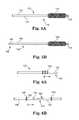
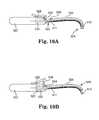
- FIGS. 10A and 10Billustrate side, cut-away views of an example of an insertion tool as described.
- the inventioninvolves surgical tools, instruments, assemblies, implantable articles for supporting tissue, and kits and systems that include combinations of these.
- examplesinclude tools, instruments, assemblies, and articles for treating pelvic floor disorders such as fecal or urinary incontinence, including stress urinary incontinence (SUI), vaginal prolapse (e.g., anterior or posterior), conditions of the pelvic floor relating to, e.g., muscle of the levator, etc.
- a surgical implantcan be used to treat a pelvic condition by surgically placing a pelvic implant to treat a condition such as prolapse (e.g., vaginal or otherwise), incontinence (male or female), etc.
- an implantcan be implanted in a male or a female patient to treat a condition such as urge incontinence; stress urinary incontinence; mixed incontinence; overflow incontinence; functional incontinence; fecal incontinence; prolapse (e.g. vaginal or uterine); enterocele (e.g. of the uterus); rectocele; cystocele; anatomic hypermobility; conditions of the pelvic floor caused by weakness or trauma of pelvic floor muscles such as the levator (“levator ani”) or coccygeus muscle (collectively the pelvic floor); other conditions caused by muscle and ligament weakness; and combinations of these.
- a conditionsuch as urge incontinence; stress urinary incontinence; mixed incontinence; overflow incontinence; functional incontinence; fecal incontinence; prolapse (e.g. vaginal or uterine); enterocele (e.g. of the uterus); rectocele; cysto
- an insertion toolthat includes a handle, a shaft, and a sheath that can cover at least a portion of the sheath.
- An exemplary insertion toolcan include a handle and a shaft that includes a proximal shaft end attached to the handle, and a distal shaft end.
- a sheathis a separate piece that can engage the shaft in at least two configurations: a covered configuration and an uncovered configuration. In the covered configuration, a sheath covers the distal shaft end, e.g., in a manner that protects and shields the distal shaft end and an optional tissue fastener that may be engaged with the distal shaft end.
- the sheathdoes not cover the distal shaft end and allows the distal shaft end and a tissue fastener that may be engaged with the distal shaft end to engage tissue.
- the sheathcan also cover (completely or partially) the proximal shaft end and a length of shaft between the proximal shaft end and the distal shaft end.
- Tool 10includes handle 2 , shaft 4 , and sheath 6 .
- Shaft 4is a solid needle shaft that includes proximal shaft end 8 attached to distal handle end 12 , and distal shaft end 14 , designed to engage a tissue fasteners.
- Recess 16is a space located at distal end 12 of handle 2 , extending longitudinally into handle 2 .
- the recessis an open space between shaft 4 and a portion of distal handle end 12 , that can receive a proximal end of shaft 6 or a portion thereof.
- recess 16is the annular space between the outer cylindrical surface of shaft 4 and the inner cylindrical surface 16 a of distal end 12 of handle 2 .
- Recess 16is sized to allow a proximal end (e.g., illustrated as a hollow cylinder) of sheath 6 to fit and become located within recess 16 , at different depths, for both covered and uncovered configurations.
- the size of a recesscan include a length (along the longitudinal distance of the handle, designated “L”) and a width or diameter (along the width of the handle).
- Another relevant lengthis length d, which is the distance from a stopping mechanism (pin 22 ) to the end of recess 16 , which is surface 15 ; this distance, d (see FIG. 1A ), is the same as the length of shaft distal end that is uncovered in an “uncovered” configuration (see FIG. 1B ).
- This distancealso relates to a maximum depth that the shaft distal end can penetrate into tissue, because the distal end of the sheath will prevent further penetration.
- a diameter of a recesscan be sufficient to allow entry of a proximal end of a sheath, and can be slightly larger than the diameter of the sheath.
- a useful diametermay be, e.g., from 0.5 to 1.0 centimeter.
- a length (L) of a recess in a handle into which a sheath can entermay be sufficient to allow the sheath to change from a covered to an uncovered configuration by entry or by further entry into the handle, i.e., movement of the sheath along the shaft in the direction toward the handle.
- the lengthca be, e.g., from 1.5 to 3.5 centimeters, such as from 2.0 to 3.0 centimeters.
- lever 20is biased by spring 24 to place pin 22 at a location within recess 16 to contact a surface at a proximal end of sheath 6 , to thereby limit movement of sheath 6 into recess 16 , toward handle 2 .
- FIG. 1Ashows sheath 6 in a covered configuration. In this covered configuration, a distal end of sheath 6 extends to cover and enclose distal shaft end 14 .
- FIG. 1Bshows sheath 6 in an uncovered configuration. In this uncovered configuration the distal end of sheath 6 does not enclose distal shaft end 14 but leaves distal shaft end 14 uncovered.
- the uncovered configurationis achieved, starting from the covered configuration, by moving sheath 6 in a proximal direction (shown by arrow A) to slide sheath 6 toward handle 2 , and allowing the proximal end of sheath 6 to become located deeper within recess 16 .
- FIGS. 2A and 2Binclude details of structure of a distal handle end including a recess, a proximal shaft end, a sheath, and a mechanical stop that engages the sheath.
- tool 40includes handle 42 , shaft 44 , and sheath 46 (e.g., in the form of a plastic tube).
- Shaft 44is a solid needle shaft that includes proximal shaft end 48 attached to distal handle end 52 .
- Recess 56is a space located at distal end 52 of handle 42 , extending longitudinally into handle 42 and sized to allow a proximal end of sheath 46 to fit and become located within recess 56 .
- Lever 60is biased by spring 64 to place pins (proximal pin 62 and distal pin 63 ) (e.g., “extensions”) at a location within recess 56 and in engagement with sheath 46 to limit movement of sheath 46 into or out of recess 56 .
- a distal surface 61 of proximal pin 62contacts a proximal end surface 54 of sheath 46 , while distal pin 63 engages aperture 59 located at the proximal end of sheath 46 .
- Proximal pin 62extends through aperture 53 of distal end 52 of handle 42
- distal pin 62extends through aperture 55 of distal end 52 of handle 42 .
- FIG. 2Ashows sheath 46 in a covered configuration.
- a distal end of sheath 46extends to cover a distal shaft end (not shown) of shaft 44 .
- sheath 46extends only partway into recess 56 ; pins 62 and 63 engage surface 54 and aperture 59 of the proximal end of shaft 46 to prevent movement of sheath 46 in a distal or a proximal direction relative to shaft 44 .
- FIG. 2Bshows sheath 46 in an uncovered configuration in which the distal end (not shown) of sheath 46 does not enclose the distal shaft end of shaft 44 (not shown) but leaves the distal shaft end uncovered.
- the uncovered configurationis achieved, starting from the covered configuration, by moving sheath 46 in a proximal direction (shown by arrow A), to slide sheath 46 toward handle 42 and allow the proximal end of sheath 46 to become located deeper within recess 56 as illustrated at FIG. 2B .
- the insertion tool of FIGS. 1A, 1B, 2A, and 2Binvolve a stopping mechanism located on a handle that associates with the sheath.
- a stopping mechanismmay be located somewhere other than the handle, e.g., along the shaft an insertion tool, or as another alternative a tool may not include or require a stopping mechanism.
- FIG. 1CAn example of an insertion tool that does not require a stopping mechanism at a handle is shown at FIG. 1C .
- Insertion tool 80includes handle 82 , shaft 84 , and sheath 86 having proximal end 87 and distal end 89 .
- Shaft 84is a solid needle shaft that includes proximal shaft end 81 attached to distal handle end 83 , and distal shaft end 91 , shown in engagement with tissue fastener 90 , which is located at a distal end of mesh extension portion 88 .
- Extension portion 88may be integrally or otherwise connected to an implant, e.g., a support portion of an implant, or may be a separate piece of an implant.
- Thumb surface 85is located at proximal end 87 of sheath 86 and allows a user to manipulate sheath 86 using a thumb, while holding handle 82 , e.g., move sheath 86 from a covered to an uncovered configuration.
- An optional stopping mechanismmay be located at the shaft, if desired.
- the stopping mechanismmay include a surface located on shaft 84 , such as an extension, that engages a surface on sheath 86 ; when engagement of the surfaces prevents movement of sheath 86 relative to shaft 84 , and disengagement of the surfaces allows movement of sheath 86 relative to shaft 84 .
- insertion tool 92includes handle 97 , shaft 96 , and sheath 95 having proximal end 93 and distal end 105 .
- Shaft 96is a solid needle shaft that includes a proximal shaft end attached to a distal handle end, and a distal shaft end, shown in engagement with tissue fastener 107 , which is located at a distal end of mesh extension portion 111 .
- Extension portion 111may be integrally or otherwise connected to an implant, e.g., a support portion of an implant, or may be a separate piece of an implant.
- a component of a mechanical stopis stop 98 , extending distally from handle 97 , which can engage a surface at the proximal end of sheath 95 .
- proximal end 93 of sheath 95can be deflected toward shaft 95 to avoid contact with stop 98 (e.g., by pressure using a user's thumb); the proximal end of sheath 95 can then move into space 99 between shaft 95 and stop 98 to allow sheath 95 to move in direction A and convert sheath 95 from a covered configuration (as illustrated) to an uncovered configuration.
- Another optional mechanical stop, surface (e.g., bump) 101 located at shaft 95cooperates with a surface (e.g., depression) 103 in sheath 95 . This stop too can be removed by deflecting proximal sheath end 93 in a direction that disengages surface 101 from depression 103 , allowing sheath 95 to move in direction A.
- a sheathcan be made of a rigid, semi-rigid, or non-rigid material that is flexible or inflexible. Examples of general types of materials are those often used with surgical tools, such as metals, ceramics, and plastics or other polymeric materials.
- a sheathcan be sufficiently flexible and optionally elastic to allow the sheath to be placed along a desired length of the shaft, including the curve.
- Certain preferred materialscan be polymeric materials that can be formed into a sheath (e.g., a cylindrical tube having two open ends) to produce a flexible yet self-supporting sheath.
- a preferred sheathcan be flexible in that the sheath can bend to a degree, such as to allow placement onto a curved shaft, and then remain bent if necessary to conform to a curvature of a tool shaft.
- a preferred sheathcan be self-supporting, meaning that if one end of the sheath is supported, the sheath does not substantially fold or bend under the force of the sheath's its own weight.
- Polymeric materials that can be useful to produce a sheath, optionally but not necessarily a flexible yet self-supporting sheathcan be polymers that include polyolefins such as polyethylene (e.g., low density polyethylene), polypropylene, polyacrylates, polymethacrylates, polyesters, urethanes, silicones, and the like.
- polyethylenee.g., low density polyethylene
- polypropylenepolypropylene
- polyacrylatese.g., polymethacrylates
- polyesterse.g., urethanes, silicones, and the like.
- a sheathcan exhibit shape and dimension to allow the sheath to cover a shaft of an insertion tool.
- Certain embodiments of sheathscan include a continuous tube of a length that is approximately the length of the shaft between a distal shaft end and a proximal shaft end at an attachment to a handle, not including a length of the shaft that is contained in a recess of the handle. Exemplary lengths of a sheath will depend on the use of the insertion tool.
- a length of a sheathcan be, e.g., from about 15 to 28 centimeters, e.g., from about 18 to 24 centimeters.
- a length of a sheathcan be, e.g., from about 8 to 15 centimeters, e.g., from about 9 to 13 centimeters. If the sheath includes a curve the length includes the full length including the length of curved portion (arclength) in a straightened condition.
- the diameter of a sheathsuch as a semi-rigid tube can be sufficient to allow the hollow interior of the tube to cover a combination of a shaft of an insertion tool and extension portion of an implant, e.g., an inner diameter of a sheath may be from 0.5 to 1.2 centimeters, such as from 0.5 to 0.8 centimeters. According to certain embodiments of sheaths, a diameter at a distal sheath end may gradually reduce, moving distally (see FIG. 1E ).
- the thickness of a sidewall of a sheathcan be consistent along the length of the sheath, and in certain preferred embodiments can be sufficient to result in a sheath that is self-supporting.
- a sidewall thickness that will be useful to achieve these functionscan depend on the sidewall material.
- a useful sidewall thickness for a sheath made of a polymeric material such as a polyolefinmay be in the range from 0.3 to 1.5 millimeter.
- a proximal end of a sheathcan optionally include an aperture in a sidewall that can be used to engage a mechanical stop such as a pin or an extension, to inhibit movement of the sheath along the length of the insertion tool shaft.
- FIG. 3Ashows a side view of sheath 70 having proximal end 72 , distal end 74 , sidewall 76 , and aperture 78 .
- sheath 70is a continuous self-supporting tube made, e.g., of a polymeric material such as polyethylene.
- the tubeis constructed of a solid polymer having openings (end apertures) at each of the proximal and distal ends, and sidewall aperture 78 within the sidewall at proximal end 72 .
- the length of sheath 70 measured from the opposing ends and including the length of the arc of the curveis sufficient to cover a needle of a tool that can reach a posterior pelvic location through a vaginal incision, e.g., from 20 to 22 centimeters. For reaching a different location, e.g., an obturator, through a vaginal incision, the length can be different, e.g., shorter.
- the inside diameter of the sheathis sufficient to enclose a solid needle shaft and a mesh material of an elongate extension portion, e.g., from 0.5 to 1.0 centimeters.
- Sidewall aperture 78is dimensioned to accept a pin, extension, or other mechanical stop useful to limit movement of the sheath relative to an insertion tool shaft, when the pin, extension, or mechanical stop engages sidewall aperture 78 .
- a sheathcan include a distal end that covers a tissue fastener, and also optionally exhibits a reduced profile for easing insertion of the sheath distal end through tissue.
- a sheath distal endcan be tapered to reduce a cross-sectional dimension such as diameter.
- FIGS. 1D, 1E, and 1Fillustrate a tapered sheath distal end. Referring to FIGS. 1E (side cross section) and 1 F (end view), sheath distal end 105 includes a tapered profile embodied as a diameter that decreases along the length of the sheath distal end, moving distally.
- the tapered distal endcan preferably include an opening that allows a tissue fastener to pass through the reduced-diameter distal end, such as by allowing passage of lateral extensions of a self-fixating tip.
- FIG. 1Fshows lateral slots 117 that allow lateral extensions 118 to pass through distal end 115 .
- a tool as describedcan be used to place an implant in a patient.
- General steps of using a tool as describedcan include engaging a tissue fastener of an implant with a distal shaft end (e.g., 14 ) and placing a sheath (e.g., 6 , 46 ) over the shaft and engaged tissue fastener.
- a sheathe.g., 6 , 46
- extension portion of the implante.g., an extension portion piece
- the shaft of the insertion toolwill be covered at least in part by the sheath, i.e., will be located within the sheath. See, e.g., FIGS.
- the assembly of the tool with sheath and engaged tissue fastenercan be inserted into a patient in the covered configuration with the distal sheath end covering the distal shaft end and engaged tissue fastener. Once inside, the position of the sheath can be changed from the covered to an uncovered configuration to expose the tissue fastener at the distal shaft end.
- an uncovered configurationas an example, a length of from 0.3 to 1.5 centimeters of the distal end of the shaft can be uncovered, such as from 0.8 to 1.5 centimeters (this measurement can be done either with an engaged tissue fastener, in which the length of the tissue fastener is included, or without an engaged tissue fastener).
- This change in configurationscan optionally be performed in conjunction with a movement of a mechanical stop, e.g., at the handle, along the shaft, or at any selected location of the tool.
- the exposed tissue fastenercan be fastened to (e.g., fixated to, inserted into, or otherwise engaged to) tissue, and the tool including the sheath can be removed.
- Exemplary implants that can be used for placement by an insertion tool as describedcan be useful for supporting any tissue of a living body, including but not limited to pelvic tissue.
- an implantcan include a tissue support portion that can be used to support pelvic tissue such as a urethra (which includes the bladder neck), bladder, rectum, vaginal tissue (Level 1, Level 2, Level 3, or combinations of these), pelvic floor tissue (e.g., levator muscle tissue), etc.
- the tissue support portionis typically placed in contact with and attached to tissue to be supported, such as by attachment using one or more sutures.
- An implantcan additionally include one or more extension portion attached or attachable to the tissue support portion.
- An extension portionmay be a portion referred to as a “scaffold” portion, which can be attached to a tissue support portion or another extension portion.
- a tissue fastener, dilator, or connector, etc.can be included at an end of an extension portion.
- the tissue support portioncan be designed to support a specific type of pelvic tissue such as the urethra, bladder (including the bladder neck), vaginal tissue (anterior, posterior, apical, etc.), rectum, tissue of the pelvic floor such as levator muscle, etc.
- the tissue support portioncan be sized and shaped to contact the desired tissue when installed, e.g., as a “sling” or “hammock,” to contact and support pelvic tissue.
- Extension portionsare pieces of material, generally elongate or otherwise extended from a tissue support portion, or in the case of a scaffold portion from another extension portion. Embodiments of extension portions can be useful to either pass through or attach to tissue of the pelvic region to thereby provide support for the tissue support portion and the supported tissue.
- One or multiple (e.g., one, two, four, or six) extension portionscan extend from a tissue support portion for attachment to tissue in the pelvic region, such as by extending to an internal anchoring point (or “fixation point”) (for attachment by bone anchor, tissue fastener, etc. as described), or through a tissue path to an external incision.
- An implantcan optionally include a scaffold portion (which can be considered a type of extension portion) that can be extended internally within a patient and secured to tissue of a pelvic region or to a location of the implant.
- a scaffold portioncan be used to support a tissue support portion or another extension portion attached to the scaffold portion, e.g., along a length of the scaffold portion and between two ends of the scaffold portion.
- a scaffold portioncan have two ends. Either end can be attached internally to tissue of the pelvic region, or to the implant, such as to a tissue support portion, another extension portion, or another scaffold portion.
- An end of a scaffold portioncan be securely (non-adjustably) attached to a tissue support portion or another extension portion, such as by a suture, rivet, staple, etc.; may be integrally formed with the tissue support portion or extension portion; or may be adjustably attached to a tissue support portion or an extension portion using an adjusting engagement.
- a scaffold portionmay also optionally include an adjusting engagement along the length of the scaffold portion.
- a “multi-piece” implantrefers to an implant that includes one or more “support portion piece,” and one or multiple “extension portion piece” (which may be a “scaffold portion piece”) as separate pieces of the implant.
- An extension portion piece or scaffold portion piececan be separate from a support portion piece, and can be connected through one or multiple adjusting engagements.
- the support portion pieceincludes a tissue support portion.
- Exemplary implantscan be made of materials and may be generally shaped and sized with certain individual features that may be found in previous implants, but can be modified to include features as described herein such as a scaffold portion, an adjusting engagement, any of the various tissue fasteners described herein, multi-piece construction, etc., and can be adapted for use according to methods described herein, e.g., involving tools that incorporate a sheath.
- An implantcan have features described in the following exemplary documents: U.S. patent application Ser. No. 10/834,943, filed Apr. 30, 2004; U.S. patent application Ser. No. 10/306,179, filed Nov. 27, 2002; U.S. patent application Ser. No. 11/347,063, filed Feb. 3, 2006; U.S. patent application Ser. No.
- PCT/US2007/004015entitled “SURGICAL ARTICLES AND METHODS FOR TREATING PELVIC CONDITIONS,” filed Feb. 16, 2007; International Publication No. WO 2008/013867 entitled “SURGICAL ARTICLES AND METHODS FOR TREATING PELVIC CONDITIONS,” published Jan. 31, 2008; International Application No. PCT/US2008/08006 entitled “SURGICAL ARTICLES AND METHODS FOR TREATING PELVIC CONDITIONS,” filed Jun. 27, 2008; International Application No. PCT/US2008/09066 entitled “PELVIC FLOOR TREATMENTS AND RELATED TOOLS AND IMPLANTS,” filed Jul. 25, 2008; and International Application No.
- Examples of commercial implantsinclude those sold by American Medical Systems, Inc., of Minnetonka Minn., under the trade names Apogee®, Perigee®, and ElevateTM for use in treating pelvic prolapse (including vaginal vault prolapse, cystocele, enterocele, etc.), and Sparc®, Bioarc®, Monarc®, and MiniArcTM for treating urinary incontinence. Implants useful according to the present description can include one or more features of these commercial implants.
- An implantmay include portions, pieces, or segments, that are synthetic of biological material (e.g., porcine, cadaveric, etc.).
- Extension portions and scaffold portions(made of a single piece or of more than one piece) may be, e.g., a synthetic mesh such as a polypropylene mesh.
- a tissue support portionmay be synthetic (e.g., a polypropylene mesh) or biologic.
- portion of implantor “implant portion” refers generally to any piece, segment, or portion (e.g., extension portion or scaffold portion) of an implant.
- segment of implant(or “implant segment”) refers to an elongate length of implant material, such as a length of an elongate section of an extension portion or a scaffold portion.)
- implants for treating vaginal prolapsecan include a central support portion and from two to four to six extension portions, and may take the form of an integral piece of mesh or other implant material, or multiple pieces of mesh or other implant material attached in a modular fashion. See, e.g., Assignee's copending U.S. patent application Ser. Nos. 11/398,369; 10/834,943; 11/243,802; 10/840,646; PCT/2006/028828; among others.
- implants for treating vaginal prolapseusing any one or a combination of devices or methods as described herein can be implants described in Assignee's copending International Patent Application No. PCT/US2007/014120, entitled “SURGICAL IMPLANTS, TOOLS, AND METHODS FOR TREATING PELVIC CONDITIONS,” filed Jun. 15, 2007, and International Application No. PCT/US2008/09066 entitled “PELVIC FLOOR TREATMENTS AND RELATED TOOLS AND IMPLANTS,” filed Jul. 25, 2008, the entirety of which is incorporated herein by reference.
- an implantcan include pieces or portions that are adjustably connected together by an adjusting engagement, which may be either a one-way adjusting engagement or a two-way adjusting engagement, to allow a portion or a segment of an implant to be moved relative to another portion or segment, and adjusted as to length, tension, or positioning.
- an extension portion piececan be attached to a support portion piece at an adjusting engagement to allow adjustment of a length of extension portion.
- a scaffold portion or scaffold portion piececan be attached to a support portion piece or to an extension portion at an adjusting engagement to allow adjustment of length or tension of a scaffold portion.
- Some adjusting engagementscan allow free two-way movement of one piece relative to another piece (e.g., a “two-way” adjusting engagement).
- This type of adjusting engagementallows easy movement of a segment of implant in two directions through an adjusting engagement.
- the force needed to move the segment of implant in one directionis substantially equal to the force needed to move the segment in the opposite direction, and, preferably, the two-way adjusting engagement does not substantially hinder the movement of a segment of implant through the adjusting engagement with frictional surfaces such as extensions (e.g., “teeth”) extending into an aperture through which the segment of implant is moved.
- a two-way adjusting engagementmay include an open (smooth) aperture that may be circular, oval, elongate such as in the form of a slit or slot, etc.
- the aperturemay optionally be reinforced by a reinforcement of a shape that is similar to the aperture, such as by a fabric or a polymeric material such as a grommet (e.g., a “loose grommet” or “eyelet”), which may be circular, or may be of another shape.
- the reinforcemente.g., grommet
- the reinforcementdefines a reinforced aperture through which a segment of implant can pass relatively freely and with the same resistance two different directions.
- adjusting engagementsmay allow for one-way adjustment such as shortening of a length of the extension portion or scaffold portion. These adjusting engagements can be referred to as “one-way” adjusting engagements, and allow adjustment of a length of an implant portion in one direction and not in an opposite direction.
- An exemplary one-way adjusting engagementcan include an aperture through which a segment of implant can extend, and one or multiple surfaces (e.g., extensions or teeth) that frictionally engage the segment of implant, e.g., by extending into or toward the aperture or otherwise contacting the segment of implant to inhibit movement of the segment of implant relative to the adjusting engagement.
- the one-way engagementcan preferentially allow movement of the segment of implant through the aperture in one direction while inhibiting movement of the segment of implant in an opposing direction.
- Still other embodiments of adjusting engagementsmay allow for two-way adjustment of a length of extension portion in one configuration (an “open” configuration), and further include a structure or mechanism that can be switched, activated, moved, removed, closed, or opened, to secure a frictional adjusting engagement at a selected location to prevent movement in either direction.
- a tissue fastener at one end of an extension portion piececan placed at tissue as desired (and “fixed” or “secured”) and a second (loose) end of the extension portion piece can be passed through an adjusting engagement, e.g., a two-way adjusting engagement.
- the engagementis adjusted to place the support portion piece at a desired position (length) of the extension portion piece.
- a second adjusting engagemente.g., a one-way grommet, is slid onto the loose end of the extension portion piece and slid along the extension portion piece to a location at the two-way adjusting engagement.
- the one-way adjusting engagementmoves easily along the extension portion piece in the direction toward two-way adjusting engagement, and does not move easily in the opposite direction.
- Implants as describedcan include a tissue fastener (also referred to herein as a “fixation element”) at a distal end of an extension portion, which is the end not attached to a tissue support portion or other portion or segment of an implant.
- a tissue fasteneralso referred to herein as a “fixation element”
- distalas used herein may be used to refer to an end of a structure that is “away from” a different structure, such as a distal end of an extension portion that is the end away from a connection to a tissue support portion.
- distalmay also (based on arbitrary selection) generally refer to a location that is relatively more posterior to a patient, and relatively farther away from a surgeon performing a method as described; “proximal” generally refers to a location that is relatively more anterior to a patient, and relatively closer to a surgeon performing a method as described. Any other convention, such as an opposite convention, could alternately be used to refer to features of devices and methods as described.)
- a tissue fastenercan be of various types, including, as examples, a self-fixating tip that is inserted into soft tissue and frictionally retained; soft tissue anchors; biologic adhesive; a soft tissue clamp that can generally include opposing, optionally biased, jaws that close to grab tissue; and opposing male and female connector elements that engage to secure an end of an extension portion to tissue.
- An implantmay also have extension portions that do not include a tissue fastener at a distal end, for example if the distal end is designed to be secured to tissue by other methods (e.g., suturing), or is intended to pass through an external incision, in which case the extension portion may include a connector, dilator, or dilating connector, which connects to an elongate tool that can be used to either push or pull the connector, dilator, or dilating connector through a tissue path to an external incision.
- a tissue fastenerat a distal end, for example if the distal end is designed to be secured to tissue by other methods (e.g., suturing), or is intended to pass through an external incision, in which case the extension portion may include a connector, dilator, or dilating connector, which connects to an elongate tool that can be used to either push or pull the connector, dilator, or dilating connector through a tissue path to an external incision.
- a tissue fastenercan be placed at and secured (or “fixated” or “fixed”) within internal tissue of the pelvic region to support the implant and pelvic tissue that is supported by the implant.
- a tissue fastenercan be placed at muscle tissue of an obturator foramen (e.g., obturator internus muscle), tissue of an arcus tendineus or surrounding an arcus tendineus, tissue of a sacrospinous ligament, tissue in a region of a sacrospinous ligament, tissue of a coccyx region, tissue of a region of an ischial spine, tissue of coccygeous muscle, tissue of iliococcygeous muscle, tissue of a uterosacral ligament, tissue of levator muscle, or at other tissue of the pelvic region.
- an obturator foramene.g., obturator internus muscle
- tissue of an arcus tendineus or surrounding an arcus tendineustissue of a sacrospinous ligament
- a tissue fasteneris a self-fixating tip.
- a “self-fixating tip” in generalcan be a structure (sometimes referred to as a soft tissue anchor) connected to an extension portion that can be implanted into tissue (e.g., muscle tissue, tendon tissue, or ligament tissue) in a manner that will maintain the position of the self-fixating tip and support the attached implant.
- Exemplary self-fixating tipscan also be designed to engage an end of an insertion tool (e.g., elongate needle, elongate tube, etc.) so the insertion tool can be used to push the self-fixating tip through and into tissue for implantation, preferably also through an incision to reach the interior of the pelvic region.
- the self-fixating tipmay engage the insertion tool at an internal channel of the self-fixating tip, at an external location such as at a base, or at a lateral extension, as desired.
- Exemplary self-fixating tipscan include one or more lateral extensions that allow the self-fixating tip to be inserted into soft tissue and to become effectively anchored in the tissue.
- a lateral extensionmay be moveable or fixed.
- the size of the self-fixating tip and optional lateral extensionscan be useful to penetrate and become anchored into the tissue.
- Exemplary self-fixating tipsare described in Assignee's copending international patent application PCTUS2007/004015, filed Feb. 16, 2007, titled Surgical Articles and Methods for Treating Pelvic Conditions, the entirety of which is incorporated herein by reference. Other structures may also be useful.
- a self-fixating tipcan have structure that includes a base having a proximal base end and a distal base end.
- the proximal base endcan be connected (directly or indirectly, such as by a connective suture) to a distal end of an extension portion (also meaning, as used herein, a scaffold portion).
- the baseextends from the proximal base end to the distal base end and can optionally include an internal channel extending from the proximal base end at least partially along a length of the base toward the distal base end.
- the optional internal channelcan be designed to interact with (i.e., engage) a distal end of an insertion tool to allow the insertion tool to be used to place the self-fixating tip at a location within pelvic tissue of the patient.
- Embodiments of self-fixating tipsalso include one or more lateral extension extending laterally (e.g., radially) from the base, such as from a location between the proximal end and the distal end, from a location at the distal base end, or from a location at the proximal base end.
- a self-fixating tipcan be made out of any useful material, generally including materials that can be molded or formed to a desired structure and connected to or attached to an end of an extension portion of an implant.
- Useful materialscan include plastics such as polyethylene, polypropylene, and other thermoplastic or thermoformable materials, as well as metals, ceramics, and other types of biocompatible and optionally bioabsorbable or bioresorbable materials.
- Exemplary bioabsorbable materialsinclude, e.g., polyglycolic acid (PGA), polylactide (PLA), copolymers of PGA and PLA.
- tissue fastenerscan be various, and can include types of fixed or moveable structures capable of securing an implant extension portion or an implant scaffold portion to soft tissue.
- the tissue fastenercan be designed to removably engage an end of a shaft of an insertion tool, while also being attached to an end of an extension portion, and also capable of being covered by a sheath when engaged at the end of the shaft.
- tissue fastenersmay include those sometimes referred to as soft tissue anchors and a self-fixating tips, and also include spring-biased fasteners that can be inserted into tissue or that may grasp and hold tissue, fasteners that include a male component that engages a female component (e.g., within tissue), or that involve extensions (tines or teeth) that can be extended from a delivery tool to splay laterally into soft tissue.
- an extension portion piececan include a segment (referred to herein as a “mesh portion,” but not necessarily of mesh) having a tissue fastener at one end.
- the extension portion piececan be configured to engage a support portion piece in a manner that allows the mesh portion to provide a structure that includes an extension portion having an adjustable length.
- An end of the extension portion piececan be placed through an adjusting engagement of a support portion piece, and the end of the support portion piece that includes the tissue fastener forms an extension portion between tissue (with which the tissue fastener becomes engaged) and the support portion piece (to which the extension portion is engaged at the adjustable engagement).
- Embodiments of extension portion pieces used with methods and implants described hereinmay also include a non-mesh portion.
- a non-mesh portionmay be, for example a suture, a set of sutures, a tape, or processed (e.g., melted or compressed) mesh.
- a non-mesh portioncan facilitate placement or movement of an extension portion piece relative to a support portion piece, e.g., through an adjusting engagement.
- a mesh of an extension portion piecemay be unwieldy for placing into an adjusting engagement such as a small-diameter grommet, small-dimension slot, toothed-slot, etc.
- a non-mesh portioncan allow easier placement (threading) of an end of an extension portion piece through an aperture of an adjusting engagement by providing a less wieldy, integral (non-mesh), more easily managed end.
- a non-mesh tapefor example, may be more easily inserted into a slot or a toothed-slot of a one-way or a two-way adjusting engagement.
- a cylindrical non-mesh portionsuch as a flexible yet rigid plastic “rod” may be more easily inserted into a round aperture such as an aperture of a grommet, compared to a loose end of a mesh material.
- a non-mesh portionmay allow for easier adjustment of the extension portion piece within an adjusting element.
- a non-meshcan exhibit reduced cross section, and friction compared to a mesh material. Additionally, an extension portion piece made of a full length of mesh material can undesirably engage tissue that can stick to mesh and become lodged in an adjusting element.
- a non-mesh portioncan be less prone to sticking to tissue during use.
- Mesh and non-mesh portions of an extension portion piececan be dimensioned to allow the mesh portion to engage an adjusting engagement when adjusted to a desired length and when a distal end tissue fastener is fastened to tissue as desired.
- a non-mesh portioncan be of a length to allow manipulation and adjustment of the extension portion piece. Exemplary lengths of a total extension portion piece can be in the range from 4 to 10 inches, including a mesh portion and a non-mesh portion (if present).
- a mesh portioncan be, for example, from 1 to 4 inches in length and a non-mesh portion (e.g., polymeric rod, suture, etc.) can be, for example, from 3.5 to 5.5 inches in length.
- a non-mesh portione.g., polymeric rod, suture, etc.
- FIG. 4illustrates one example of a useful implant ( 231 ), having certain features described herein.
- Support portion piece 205can be placed, e.g., to treat anterior vaginal prolapse.
- Implant 200includes support portion piece 205 having two-way apertures (e.g., grommets or openings) 204 and 206 .
- Extension portion pieces(not shown) can be threaded loosely through each of apertures 204 and 206 , respectively, to allow substantially free two-way movement of each extension portion piece through each aperture ( 204 , 206 ), for adjustment.
- Tissue fasteners 216can be placed at opposing obturator foramen of a patient, while support portion piece 205 is placed to support vaginal tissue.
- Posterior tissue support extension 226is optional and may be place to support posterior vaginal tissue.
- Adjusting engagements 204 and 206may be one-way adjusting engagements (e.g., grommets) or two-way adjusting engagements (e.g., grommets).
- Extension portion piecesmay include a length that is entirely mesh, or may include a mesh portion and a non-mesh portion, FIGS. 5A and 5B or otherwise described herein.
- a grommet management tool as illustrated at either of FIGS. 6A and 6B , or as otherwise described herein,can be used to place a grommet on each non-mesh portion of such extension portion pieces.
- An adjusting toolmay be used to adjust position of an adjusting engagement.
- Mark 217 on implant 231includes a centerline mark and an orientation mark.
- the markis on one side of the implant, e.g., to identify a top surface of the implant relative to a bottom surface.
- the centerline mark 217 aruns vertical (as illustrated), which is from an anterior to a posterior location on the implant, and is located to mark the centerline of the implant piece.
- a portion of the mark, 217 b , perpendicular to centerline mark 217 aindicates a particular side of the implant, which as illustrated is a patient-left-side of the implant. This may be useful, for example, to confirm correct orientation of the implant such as that the correct side of the implant is being placed upward.
- Exemplary dimensions of an implant as shown at FIG. 4can be: length A, from 5 to 7 centimeters, e.g., from 5.5 to 6.5 centimeters; length B, from 10 to 12 centimeters, e.g., from 10.5 to 11.5 centimeters; length C, from 5.5 to 7.5 centimeters, e.g., from 6 to 7 centimeters; length D, from 3.5 to 5.5 centimeters, e.g., from 4 to 5 centimeters; length E, from 2 to 4 centimeters, e.g., from 2.5 to 3.5 centimeters; and length F, from 4 to 6 centimeters, e.g., from 4.5 to 5.5 centimeters.
- FIG. 5Aillustrates an example of an extension portion piece (alternately referred to herein as a “fixation arm”) that includes a mesh portion and a non-mesh portion.
- Extension portion piece 110includes mesh portion 114 and non-mesh portion 112 , in the form of two sutures 113 .
- Tissue fastenere.g., a self-fixating tip
- Sutures 113are attached to a proximal end of mesh portion 114 , such as by knots.
- Non-mesh portion 112is illustrated to be in the form of two sutures, but may alternately by more or fewer sutures, such as one suture, or three sutures, optionally tied or braided. Still alternate forms of non-mesh portion 112 may be a polymeric tape, a narrow fabric, or the like, any of which can be selected to be easily threaded through an aperture of a desired adjusting engagement.
- FIG. 5Billustrates another example of an extension portion piece (alternately referred to herein as a “fixation arm”) that includes a mesh portion and a non-mesh portion.
- Extension portion piece 100includes mesh portion 104 and non-mesh portion 102 .
- Tissue fastener (e.g., self-fixating tip) 106is attached to a distal end of mesh portion 104 .
- Polymeric (e.g., polypropylene) rod 102is attached to (preferably integral to) a proximal end of mesh portion 104 .
- Polymeric rod 102can be formed by any method and may be integrally attached to mesh portion 104 , or attached by any technique.
- polymeric rod 102may be prepared by starting with a length of mesh material that is integral to mesh portion 104 .
- the length of meshcan be heat treated at a desired melting temperature (according to the type of polymer of the mesh) to melt the mesh into a polymeric rod having stiff yet flexible mechanical properties.
- a desired heat-treating temperaturemay be in the range from 450 to 520 degrees Fahrenheit.
- Polymeric rod 102can be of useful dimensions, such as a length in the range of about 3.5 to 5.5 inches and a width dimension (e.g., diameter) useful to engage a dilator, e.g., about 1/16 of an inch, or from about 1 to 4 millimeters.
- proximal end 109 of polymeric rod 102can be shaped to accept or matingly engage an end of a grommet-management tool, such as a polymeric rod, that can facilitate placement of a grommet or other adjusting engagement onto a proximal end of a non-mesh portion of an extension portion piece.
- a grommet-management toolsuch as a polymeric rod
- a user of an extension portion piecesuch as extension portion piece 100 , may place a grommet (e.g., a one-way grommet) onto a proximal end of a non-mesh portion by hand, using fingers. This can be clumsy, especially in potentially confined or deep locations of a pelvic region.
- a grommet management toolholds one or multiple grommets.
- An end of the grommet management toolcan engage a proximal end of a non-mesh portion of an extension portion piece in a manner to allow the end of the grommet management tool to align and mate against the proximal end of the extension portion piece. Once the ends are engaged, a grommet can slide from the grommet management tool, directly onto the proximal end of the non-mesh portion of the extension portion piece.
- a grommet management toolmay contain a single grommet, or multiple grommets, and can be used to transfer the one or multiple grommets onto multiple different extension portion pieces of a single or multiple pelvic implants.
- a grommet management toolcan ensure that control of a grommet (or other adjusting engagement) and a location of a grommet are not lost during a surgical procedure, and a grommet can be prevented from becoming a free-standing, separate piece with the potential of becoming lost during a surgical procedure.
- FIG. 6Aillustrates grommet management tool 120 , which is a rod, such as a polymeric (e.g., polypropylene) rod with a diameter that matches a diameter of polymeric rod 102 .
- One-way (alternately two-way) grommets 124are aligned along a length of grommet management tool 120 .
- Distal end 124includes channel or bore 122 that is complementary to cylindrical extension 108 at proximal end 109 of extension portion piece 100 . These complementary surfaces can be engaged to allow transfer of a grommet from tool 120 to polymeric rod 102 .
- non-mesh portion 102 of extension portion piece 100can be passed through an adjusting engagement of an implant.
- the implant and extension portion piececan be manipulated and placed as desired, such as at locations within a pelvic region.
- Channel 122 of grommet management tool 120can be placed over cylindrical extension 108 , and a grommet 124 can be slid in direction B (see FIG. 6 A) and transferred from grommet management tool 120 onto proximal end 109 of extension portion piece 100 .
- One-way grommets 124move easily along an extension portion piece in direction B, and are inhibited from moving in a direction opposite of direction B when placed on a mesh portion such as mesh portion 104 .
- grommet 124can slide to engage mesh portion 104 , and contact the adjusting engagement of the tissue support portion or support portion piece to secure a relative position of mesh portion 104 to the tissue support portion or support portion piece, e.g., to fix a length of an extension portion of mesh portion 104 .
- a grommet management tool such as tool 120can be made of a plastic, metal, or other useful material.
- a grommet management toolcan be prepared in the same manner used to make a polymeric rod non-mesh portion 102 , such as by melting a length of mesh and molding to form a polymeric rod. Other methods can also be used, such as by extruding, injecting molding, etc.
- the engagement between distal end 124 of grommet management tool 120 , and proximal end 109 of non-mesh portion 102includes complementary cylindrical surfaces.
- Other engagementscan also be useful, such as complementary conical surfaces, square surfaces, etc.
- a feature of a non-mesh portion of an extension portion piece, or of a grommet management toolmay include a feature that allows a one-way grommet to pass only if the one-way grommet is correctly oriented for movement in a desired direction.
- An example of this featurecan be a shoulder or notch located at a proximal end of a non-mesh portion of an extension portion piece (or, alternately, at a distal end of a grommet management tool).
- grommet management tool 130engages proximal end 132 of an extension portion piece.
- the engagementincludes complementary conical surfaces 134 to allow alignment and mating between the two ends.
- Notch 140 and shoulder 142allow one-way grommet 136 to transfer from tool 130 onto non-mesh portion 132 , because grommet 136 is oriented in a direction to allow movement in direction C and inhibit movement in a direction opposite of direction C.
- Notch 140 and shoulder 142prevent one-way grommet 138 from transferring onto non-mesh portion 132 .
- Grommet 138is oriented in a direction to allow movement in the direction opposite of direction C and not in direction C.
- Teeth 139 of grommet 138would engage shoulder 142 and stop grommet 138 from moving past shoulder 142 in direction C.
- Notch 140 and shoulder 142are illustrated to be located on non-mesh portion 132 , but alternately could be included on grommet management tool 130 .
- a system as describedalso includes an insertion tool that generally includes a handle and a shaft.
- the shaftcan be a solid structure such as a solid needle that is optionally curved in two or three dimensions.
- the distal end of the needlecan include a surface that engages a tissue fastener by fitting inside a channel in a base of the tissue fastener, e.g., as with embodiments of self-fixating tips.
- a shaftcan include a hollow center such as that of a trocar, or a moveable mechanism that can engage a self-fixating tip by grasping or other mechanical engagements.
- insertion toolsmay generally be useful to engage and place a tissue fastener secured to an extension portion (or, as described herein, a scaffold portion) of an implant as described.
- Various types of insertion toolsare known, and these types of tools and modifications thereof can be used according to the present description to install an implant.
- useful insertion toolsinclude those types of tool that generally include a thin elongate shaft (e.g., needle); a handle attached to one end (a proximal end) of the shaft; and an optional distal end (or “tip”) of the shaft adapted to engage a tissue fastener connected to extension portion (including a scaffold portion).
- the needlecan facilitate placement of the distal end of the extension or scaffold portion at a desired anatomical location that may be internal or through a tissue path to an external incision.
- Exemplary insertion tools for treatment of incontinence and vaginal prolapseare described, e.g., in U.S. patent application Ser. Nos. 10/834,943, 10/306,179; 11/347,553; 11/398,368; 10/840,646; PCT application number 2006/028828; and PCT application number 2006/0260618; each of which is incorporated herein in its entirety by reference.
- Tools described in these patent documentsare designed for placement of an implant in a pelvic region for the treatment of prolapse, male or female incontinence, etc.
- Exemplary insertion toolscan be similar to or can include features of tools described in the above-referenced patent documents.
- those insertion toolsmay be modified, such as to allow the insertion tool to be used to place a self-fixating tip through a vaginal or a medial incision, to engage tissue within the pelvic region.
- the insertion toolcan be designed, shaped, and sized, to include an elongate shaft that may be straight or that may be curved in two or three dimensions, that can be inserted through a vaginal incision (for female anatomy) or through a perineal incision (for male anatomy), and extend from that incision to or through pelvic tissue for placement of a distal end of an extension portion.
- An adjusting toolcan be an elongate tool that includes a distal end that engages an adjusting mechanism, to manipulate and optionally cause movement of the adjusting mechanism relative to a portion of implant.
- FIGS. 7A and 7Bshow side and top views of adjusting tool 170 , useful for moving an adjusting engagement such as a grommet along a length of a segment of an implant such as a segment of an extension portion or a scaffold portion.
- Tool 170includes elongate shaft 172 and distal end 174 .
- Slot 176 at distal end 174can be slid past a segment of implant to place a segment of implant at a location within aperture 179 .
- Aperture 179is defined in part by opposing arms 178 (illustrated to be curved, but optionally straight, angled, etc.) that extend laterally and optionally distally from a distal end of shaft 172 , to define aperture 179 and slot 176 .
- Bottom surfaces of arms 178can be used to apply pressure to an adjusting engagement (e.g., grommet) located on the segment of implant, and move the grommet, preferably in a direction along the segment of implant to adjust a length of an extension portion or scaffold portion.
- Slot 176is optional, and distal end 174 could alternately include a closed aperture through which a portion of implant could be threaded place distal end 174 in contact with an adjustable engagement.
- a slotmay define an opening that is in the range from 0.5 to 1.2 centimeters, e.g., from 0.5 to 1.0 centimeter.
- An aperturemay have the same or similar dimensions, or may be the same width or wider than the slot, such as having a diameter in the range from 0.5 to 1.2, e.g., 0.5 to 1.0 centimeter.
- Surfaces for engaging an adjusting engagementmay correspond to a size of surfaces of the adjusting engagement, such as having surfaces that match surfaces of a flange of a grommet.
- FIGS. 8A and 8BAnother embodiment of adjusting tool is shown at FIGS. 8A and 8B .
- This embodiment of adjusting tool 170includes features of tool 170 as illustrated at FIGS. 7A and 7B , and also includes an optional second set of arms around aperture 179 , located in alignment with arms 178 .
- FIGS. 8A and 8Bshow side and top views of this embodiment of adjusting tool 170 .
- this embodiment of tool 170includes a second set of arms, 184 , that are aligned with arms 178 and that define additional length of aperture 179 .
- optional arms 186are structured to prevent tissue from becoming lodged inside of an adjusting engagement (e.g. a grommet) during movement of grommet 32 in a direction N along a segment of implant.
- an adjusting engagemente.g. a grommet
- tissuemay come into contact with the mesh or the grommet and (absent arms 186 ) can tend to be forced into the aperture of the grommet.
- Arms 186become located on the side of the grommet that moves into tissue, and deflect and block tissue from entering an aperture of the grommet.
- second arms 186can be used to move a two-way grommet in a direction opposite of the direction of movement provided by arms 178 ; i.e., this embodiment of an adjusting tool allows for a two-way grommet to be moved in two different directions (distally, and proximally) along an implant segment.
- slots 176 and 184 at distal end 174can be slid over a segment of implant to place a segment of implant at a location within aperture 179 (defined by and between sets of arms 178 and 186 ).
- FIG. 10Ashows that bottom surfaces 182 of arms 186 can deflect and block tissue from entering an aperture of adjusting engagement 192 , which may be, e.g., a one-way or a two-way grommet used to adjust the location of implant portion 190 relative to implant segment 198 , which includes tissue fastener 196 placed within tissue 194 .
- embodiments of implants as describedcan be implanted according to methods that include placement of a tissue support portion of an implant at a location to support pelvic tissue, and placement of a tissue fastener attached to an extension portion of an implant (e.g., an extension portion piece), including optional use of an insertion tool that includes a sheath as described.
- a methodmay include steps such as engaging a tissue fastener with the distal shaft end, placing a sheath over the shaft and engaged tissue fastener, and inserting the shaft and engaged tissue fastener into a patient with the sheath placed over the shaft in the covered configuration.
- the sheathmay engage an optional mechanical stop to maintain the position of the sheath in the covered configuration.
- the mechanical stopmay be removed to allow the sheath to move (e.g., slide in a proximal direction along the shaft) to an uncovered configuration that uncovers the tissue fastener.
- the tissue fastenercan then be fastened to tissue of a patient, e.g., soft tissue of a pelvic region. If the tissue fastener is a self-fixating tip, the self-fixating tip can be fastened to the soft tissue by using the handle and shaft to push the self-fixating to into the soft tissue.
- tissue fastenerfastens to tissue by another mechanism, such as by mechanical grasping, optionally using a shaft that opens or closes a grasping mechanism of the tissue fastener, then the tissue fastener can be caused to engage tissue by manipulation of an actuator or other actuating mechanism to secure the tissue fastener to tissue.
- One or more extension portions and optional scaffold portionsare placed (by use of an insertion tool with a sheath, or otherwise) for use in supporting the tissue support portion.
- a tissue fastener at a distal end of an extension portioncan be placed at internal tissue of the pelvic region such as muscle, ligament, tendon, fascia, bone, etc.
- an extension portionmay include a connector, for connecting to a tool that pulls the connector and extension portion through a tissue path leading to an external incision (e.g., at an external perirectal region, or through an obturator foramen and to an external incision at an inner thigh).
- an extension portionmay not include a connector or a self-fixating tip but may be connected to tissue or led through a tissue path internal to the patient, or may be passed through a tissue path and an external incision.
- a tissue fastener at a distal end of a scaffold portioncan be connected to internal tissue of the pelvic region such as muscle, ligament, tendon, fascia, bone, etc.
- an end of a scaffold portioncan also be attached to a tissue support portion or an extension portion of an implant.
- An extension portion or a support portion piececan be attached to the scaffold portion at a location between the ends of the scaffold portion.
- Embodiments of methodscan be performed using a medial incision such as through a vaginal incision (for female anatomy) or perineal incision (for male anatomy), and by use of an insertion tool (e.g., any insertion tool described herein) that engages a distal end of the extension portion (such as by engaging a tissue fastener) and passes the distal end to a desired location within a pelvic region of a patient.
- a medial incisionsuch as through a vaginal incision (for female anatomy) or perineal incision (for male anatomy)
- an insertion toole.g., any insertion tool described herein
- An end of an extension portion or scaffold portioncan be attached to any desired tissue of the pelvic region, or passed through a desired tissue path to an external incision.
- a tissue fastenercan be attached at the end of the extension or scaffold portion.
- the tissue fastenercan be attached to any desired tissue, for example soft tissue such as a muscle (e.g., of the obturator foramen, obturator internus, obturator externus, levator ani, coccygeous, iliococcygeous); ligament such as the sacrospinous ligament or surrounding tissue; tendon such as the arcus tendineus or surrounding tissue (e.g., a region of the arcus tendineus, see WO 2007/016083, published Feb. 8, 2007, and entitled “Methods and Symptoms for Treatment of Prolapse,” the entirety of which is incorporated herein by reference); including tissue at or near an ischial spine, e.g., at a region of an ischial spine.
- soft tissuesuch as a muscle (e.g., of the obturator foramen, obturator internus, obturator externus, levator ani, coccygeous, iliococc
- Kit 500includes support portion piece 502 , two extension portion pieces 504 (each shown to have a mesh portion and a non-mesh portion), sheath 520 for use with insertion tool 510 , insertion tool 530 , optional adjusting tool 506 , and optional grommet management tool 508 .
- Sheath 520is in the form of a self-supporting polymeric (e.g., polypropylene) tube having proximal end 522 , distal end 524 , and sidewall aperture 526 .
- Insertion tool 510can be as described, e.g., as illustrated at FIGS. 1A, 1B, 1C, 1D, 2A, and 2B .
- insertion tool 510includes handle 507 , including recess 532 , and lever 528 including pin (mechanical stop) 530 .
- a distal end of shaft 511 of insertion tool 510engages tissue fasteners 512 , of extension portion pieces 504 , e.g., for placing tissue fasteners 512 at a posterior location of a pelvic region such as at a sacrospinous ligament.
- Aperture 526 of sheath 520engages pin 530 when sheath 520 covers shaft 511 in a covered engagement, wherein proximal end 522 partially enters recess 532 . In an uncovered engagement, proximal end 522 extends further into recess 532 to uncover the distal end of shaft 511 .
- Extension portion pieces 504include a mesh-portion and a non-mesh portion, but entirely mesh extension portion pieces could be used.
- Optional adjusting tool 506can be as described, e.g., as illustrated at FIGS. 7A and 7B , or 8 A and 8 B.
- Optional grommet management tool 508can be as described, e.g., as illustrated at FIG. 6A or 6B . End 514 of grommet management tool 508 can matingly engage ends 516 of non-mesh portions of extension portion pieces 504 , such as at cylindrical bores (shown in shadow).
- Insertion tool 530includes a handle and a shaft, the distal end of the shaft being capable of engaging tissue fasteners 513 of implant support portion piece 502 , to allow insertion tool 530 to place tissue fasteners 513 transvaginally, at an anterior location of the pelvic region, e.g., each at an opposite location of an obturator foramen.
- Support portion piece 502can be designed to support posterior vaginal tissue, anterior vaginal tissue, vaginal vault tissue, or another pelvic tissue, and can include optional features such as additional extension portions or scaffold portions or additional adjusting engagements (not shown).
- support portion piece 502can comprise a support portion piece or implant as described or illustrated herein.
- Apertures 518can be one-way adjusting engagements or two-way adjusting engagements.
- insertion tool, 510 , extension portion piece 504 , and sheath 520can be used by initially placing tissue fastener 512 in contact with distal end 515 of tool 510 .
- sheath 520can then be placed over shaft 511 and extension portion piece 504 (each is within sheath 520 ).
- Proximal end 522 of sheath 520contacts pin 530 , preventing proximal end 522 from fully entering recess 532 of handle 507 .
- the covered configurationcan be used for inserting a tool, with engaged tissue fastener and extension portion (e.g., extension portion piece), into a patient, e.g., through a transvaginal or other incision, to place tissue fastener 512 at a location in the body near a fixation site.
- tissue fastener and extension portione.g., extension portion piece
- FIG. 10Billustrates the uncovered configuration wherein distal end 524 of sheath 520 does not cover tissue fastener 512 engaged with distal end 515 of shaft 511 of insertion tool 510 ; pin 530 has been moved from engaging proximal end 522 , and proximal end 522 has been moved into recess 532 .
- tissue fastener 512can engage tissue at a fixation site.
- An example of a method as described herein for treating vaginal prolapsecan include placing a tissue support portion at tissue of the anterior or posterior vagina or vaginal vault, and fixing one and optionally two posterior extension portions extending from the tissue support portion to a sacrospinous ligament, then securing two anterior extension portions to opposing obturator foramen. Placement of one or all of the extension portions may be performed using an insertion tool that incorporates the use of a sheath as described herein.
- An example of a system according to the present descriptionincluding an implant and insertion tool for treating vaginal prolapse, can be as follows.
- the systemcan be used to treat or repair vaginal prolapse without external needle passes, by use of a single, transvaginal incision.
- One embodiment of this type of systemcan be useful to treat posterior vaginal prolapse by placement of extension portions of an implant at locations that include a sacrospinous ligament, a coccygeus muscle, or both.
- the implantcan be implanted, fixated, and adjusted, as desired, transvaginally, via a single vaginal incision. Unlike other similar systems and methods this described embodiment can be implanted in the body without external trans-gluteal needle passes and is, thus, less invasive.
- the systemgenerally includes fixation arms (extension portion pieces) (e.g., as illustrated at FIG. 5B , a center graft (a support portion piece) (e.g., as illustrated at FIG. 4 ), a delivery device (insertion tool) (e.g., as illustrated at FIG. 1A, 1B, 1C, 1D, 2A , or 2 B), and adjusting engagements.
- fixation armsextension portion pieces
- center grafte.g., as illustrated at FIG. 4
- a delivery deviceinsertion tool
- adjusting engagementse.g., as illustrated at FIG. 1A, 1B, 1C, 1D, 2A , or 2 B
- These tools and implant piecescan be part of a system as shown at FIG. 9 .
- a fixation armcan fixate to an internal fixation site, guide the center graft within the body, and aid in internal adjustment of the center graft.
- Each fixation armgenerally includes a stem (non-mesh portion), a mesh segment (mesh portion), and a fixation element (tissue fastener).
- Components of a fixation armcan be made of polypropylene or any material now known to or yet developed by a person skilled in the art.
- FIG. 5Bshows an example of a fixation arm that includes a solid polymeric stem ( 102 ).
- a distal end of stem 102can be over-molded on an end (proximal end) of mesh segment 104 .
- stem 102 and mesh segment 104can be made of a single piece of polymeric material.
- a fixation element ( 106 )can be over-molded on another (distal) end or portion of mesh segment 104 .
- a proximal end of the stem ( 109 )can be used by a physician during surgery to guide placement of and manipulate, relative to each other: loose eyelet (e.g., a one-way adjusting grommet) of the center graft, the locking eyelet holder (e.g., a grommet management tool), the locking eyelets (e.g., one-way adjusting grommet), and the accessory tool (adjusting tool).
- loose eyelete.g., a one-way adjusting grommet
- the locking eyelet holdere.g., a grommet management tool
- the locking eyeletse.g., one-way adjusting grommet
- accessory tooladjusting tool
- the stemcan allow the loose eyelets of the center graft and the locking eyelets to be transferred into the body of a patient without encountering tissue-catching issues; e.g., a stem may extend from an incision after placement of a fixation arm, and the stem may be threaded through the loose eyelet outside of the body and away from the confined surgical site.
- the mesh segment (mesh portion) of the fixation armcan allow free passage of a loose eyelet while permitting at least one locking eyelet to move in one direction to secure the loose eyelet in place.
- the fixation elementcan allow strong acute fixation in the sacrospinous ligament or any other soft tissue.
- the center graftgenerally comprises a graft portion (e.g., mesh or biologic material) and optional loose eyelets.
- the graft portioncan be made of extra-light polypropylene (ELPP), a porcine graft, any material now known to or yet developed by a person skilled in the art for use in biological implants, or combinations of materials.
- ELPPextra-light polypropylene
- One loose eyeletcan be over-molded on a side of the graft portion and another loose eyelet can be over-molded on another or opposite side of the graft portion.
- the loose eyeletscan be used to allow a physician to translate the center graft into and out of the body for proper positioning. In one embodiment, the positioning and repositioning of the center graft is accomplished on the stem prior to being secured with the locking eyelets.
- portions of the mesh armscan have one or more rolls or folds disposed along a length thereof that are sutured prior to system implantation and held together, e.g., by sutures, staples, adhesive, or another fastener. If the implant is too tight, a physician or other medical staff can cut the sutures holding the rolls or folds together in vivo to increase a length of one or more of the mesh arms. The increased length loosens the center graft.
- the locking systemgenerally includes the locking eyelets (e.g., one-way adjusting grommets), an optional locking eyelet holder (grommet management tool), loose eyelets (e.g., two-way adjusting grommets), and an optional accessory tool (e.g., adjusting tool). All components of the locking system can be made of polypropylene, or any material now known to or yet developed by a person skilled in the art.
- the locking eyeletcan be a one-way tensioning device that, once engaged with the mesh segment of the fixation arm, permits only increased tensioning of the center graft.
- the locking eyeletcan associate with a loose eyelet of the center graft to fixate the center graft on the mesh segment of the fixation arm.
- the locking eyeletcan feature generally inwardly radiating teeth that can be oriented at an angle to allow translation along the fixation arm in one or both directions along the stem of the fixation arm and to prevent translation in a direction toward the stem of the fixation arm once engaged with the mesh segment (e.g., mesh portion).
- the locking eyelet holdercapable of being manipulated by a physician or other medical staff, keeps the locking eyelets correctly oriented and can mate with an end of the fixation arm to translate the locking eyelets when necessary. Loose eyelets can be over-molded on the center graft.
- Each loose eyeletcan be loaded on the proximal end of the stem of the fixation arm and can be translated on the fixation arm for proper positioning of the center graft.
- the accessory toolcan aide a physician or other medical staff when translating the loose eyelets of the center graft and the locking eyelets on the fixation arm.
- the accessory toolcan be especially helpful in small body cavities or hard-to-reach locations within a patient, such as but not necessarily in a pelvic region.
- the delivery devicegenerally includes a shaft such as a solid needle, and a handle.
- the needlegenerally comprises a solid length of shaft and a tip at the distal end, wherein the tip engages a fixation element (e.g., tissue fastener, such as a self-fixating tip).
- the needlecan transport the fixation element of the fixation arm to a desired fixation site (e.g., at soft tissue of a pelvic region) and can perform placement of the fixation element in soft tissue or tissue selected by the physician or other medical staff.
- the followingcan be a method of implantation of the above system, for treating vaginal prolapse. This method can be performed with an insertion tool that involves a sheath as described, or without a sheath:
- step 21Repeat step 20 to load one locking eyelet on the other fixation arm.
- Embodiment of methods that incorporate these stepscan treat cystocele, rectocele, enterocele, vault prolapse, and/or any pelvic dysfunction relating to rectal, vaginal, or bladder issues.
- Embodiments of fixation elementscan be over-molded on the free end of each mesh arm.
- the fixation elementcan have a bore to receive the needle of a delivery device.
- the fixation element or the needlecan dilate the tissue.
- the fixation elementcan then be attached at a location at a posterior pelvic region, such as any of a: sacrospinous ligament, coccygeus muscle, iliococcygeus muscle, arcus tendineus (white line), fascia at the ischial spine, puborectalis muscle, piriformis muscle, fascia at the obturator canal, or any location on the levator ani.
- Other fixation sitesare also considered to be within the spirit and scope of the invention and the above list should not be considered limiting.
- Embodiments of delivery devicescan generally include a shaft (e.g., a solid needles shaft), a handle, and a distal tip at the end of the shaft that engages a fixation element.
- the needlecan provide transport of the fixation element of the center graft to the target fixation site and can perform placement of the fixation element in tissue.
- the needlecan have many possible shapes, depending where the fixation element is intended to fixate. For example, three-dimensionally curved helical-shaped needles can be used near the white line. Two-dimensionally curved sickle-shaped needles can be used near the sacrospinous ligament area.
- the needlecan have a sliding component that pushes the needle and the fixation element into the tissue.
- the sliding componentcan be a needle-sub-needle combination with the sub-needle having a smaller diameter cross-section than the needle.
- the sub-needlecan be disposed in a cavity in the needle or it can be disposed adjacent to and travel generally parallel with a longitudinal axis of the needle.
- An actuatorcan be disposed on the needle to move the sub-needle between a retracted position and an extended position, with the extended position being used for placement of the fixation element.
- the sliding componentcan also be disposed on a finger tool as well.
- the finger toolincludes a receptacle having a shape adapted to receive a finger or thumb of a physician.
- a needle or upright member having enough rigidity for successful placement of the fixation elementcan be disposed to and extend generally away from the receptacle.
- the fixation elementcan then be disposed on (engage) a free end of the upright member (e.g., needle).
- the upright membercan having any size and shape necessary for fixating the fixation element into the tissue.
- the upright membercan be generally straight, curved, hooked, or angled.
- the systemcan include support of the apical portion of the vagina.
- the inferior aspect of the center graftcan fixate at the sacrospinous ligament.
- the shape of the center graftcan be modified to accommodate the new fixation site and to optimize structural support of the anterior vaginal compartment.
- FIG. 1Another embodiment of a system generally can include a center graft, fixating arms, a delivery system (insertion tool) including a sheath, a latch-and-release mechanism for engaging the sheath with the insertion tool, and optional accessory tool or grommet management tool.
- a delivery systeminsertion tool
- a latch-and-release mechanismfor engaging the sheath with the insertion tool
- optional accessory tool or grommet management tooloptional accessory tool or grommet management tool.
- Edges of a center graftcan be made of any material now known to or yet developed by a person skilled in the art. Edges of the center graft can be curved to reduce curling under tension. The shape of the center graft can be tailored for centering and orientation.
- the center graftgenerally comprises a superior aspect (sometimes referred to as an anterior portion), an inferior aspect (sometimes referred to as a posterior portion), and optionally a graft tail.
- the superior aspectcan fixate through extension portions at the obturator internus muscle.
- the superior aspectcan include fixation elements, one on each side.
- the inferior aspectcan fixate through extension portions at or near the sacrospinous ligament.
- the inferior aspectcan preferably include locking eyelets, one on each side.
- the locking eyeletcan associate with a loose eyelet of the center graft to fixate the center graft on the mesh segment of the fixation arm.
- the locking eyeletcan feature teeth that can be oriented at an angle to allow translation along the fixation arm and to prevent translation in the opposite direction once engaged with the mesh segment of the fixation arm.
- the graft tailcan be trimmed without negatively affecting its load-bearing portion.
- the angle of the inferior attachment tabcan approximate the angle between the mesh orientation and the sacrospinous ligament attachment point.
- the delivery systemgenerally comprises an inferior delivery device (insertion tool) and a superior delivery device (insertion tool).
- the inferior delivery devicegenerally comprises a needle, a sheath, a handle, and optional a latching-and-release mechanism (e.g., as does tool 510 , with shaft 520 , of FIG. 9 ).
- the needleis used to transport and fixate the fixation element of a fixation arm to the sacrospinous ligament or any other desired fixation site.
- a superior delivery devicemay include a sheath, or may include a needle without a sheath (as does tool 530 of FIG. 9 .
- a sheathcan perform at least three functions. First, a sheath can shield the fixation arm (including the tissue fastener) during delivery to minimize the possible inconvenience of the fixation element (tissue fastener) falling off or the fixation element getting caught on tissue. Second, a sheath can protect the physician's glove and finger from snagging on the fixation element during delivery. Third, a sheath can provide a hard stop against over-insertion of the fixation element into the tissue.
- the handle of an insertion tool adapted for use in conjunction with a sheathcan feature a latch-and-release mechanism, which includes a mechanical stop, to hold the sheath secure to the handle of the inferior delivery device and to prevent premature exposure of the fixation element during deployment deep inside the pelvis.
- the latch-and-release mechanismreleases the sheath prior to fixation element insertion into soft tissue (e.g., sacrospinous ligament, coccygeus muscle, levator ani muscle, obturator foramen, etc.).
- Soft tissuee.g., sacrospinous ligament, coccygeus muscle, levator ani muscle, obturator foramen, etc.
- a sheath in conjunction with a latch- and release mechanism (and optional handle recess)can also control the depth of fixation element insertion into soft tissue.
- the latch-and-release mechanismcan be a lever generally comprising a rigid bar and a fulcrum. (Other options located on an insertion tool handle, shaft, or elsewhere, are also possible, as will be appreciated.)
- the rigid barcan feature a thumb-engaging portion and a sheath engaging portion (e.g., mechanical stop, pin, or “trigger-latch”) at opposite ends from one another. At rest, the sheath-engaging portion engages or abuts with the sheath to hold the sheath secure to the handle. When the thumb-engaging portion is depressed, the rigid bar can pivot on the fulcrum causing the sheath-engaging portion to disengage with the sheath.
- An example of an inferior delivery needleincluding a sheath, can include one or more features such as: a leading edge of trigger latch is angled, allowing the sheath to raise the trigger latch as the sheath presses against the trigger latch during a locking procedure; when the sheath reaches a desired locking position, the latch drops down to engage an aperture in a sidewall at a proximal end of the sheath, restricting the sheath from moving forward or backward; depth limiting stop (e.g., a length of a recess in a handle) limits the sheath from retracting too far into the handle, thus limiting the length of needle tip exposed past the sheath and inserted into the tissue; the distance from the latch stop to the depth limiting stop (e.g., approximately distance d of FIGS. 1A and 1B ) is the desired depth limiting distance.
- a leading edge of trigger latchis angled, allowing the sheath to raise the trigger latch as the sheath presses against the trigger latch during a locking
- a superior insertion toolcan include a needle (such as a solid metal needle) and preferably a handle; the superior insertion tool can optionally include a sheath.
- the needlecan be used to transport and fixate the fixation elements of the center graft to the obturator internus muscle.
- the needlecan be curved to allow for direct approach to the muscle.
- the needlecan feature a flat surface on its tip that corresponds to a surface of a fixation element, to prevent rotation of the fixation element and to control orientation of the fixation element (e.g., and tines or extension portions of the fixation element) with respect to the muscle fiber.
- the followingcan be a method of implantation of the above system, including an inferior insertion tool that works in conjunction with a sheath, and a superior insertion tool that does not require a sheath:
- a fixation element of the center graftonto the needle tip of the superior delivery device (e.g., a fixation element 513 of an implant, and delivery device 530 , illustrated at FIG. 9 ).
- Various embodiments disclosed hereincan be combined with neuromuscular stimulation to treat pelvic prolapse and any pain/discomfort associated with it or post-cancer or other reconstructive surgery.
Landscapes
- Health & Medical Sciences (AREA)
- Life Sciences & Earth Sciences (AREA)
- Surgery (AREA)
- General Health & Medical Sciences (AREA)
- Public Health (AREA)
- Biomedical Technology (AREA)
- Heart & Thoracic Surgery (AREA)
- Engineering & Computer Science (AREA)
- Animal Behavior & Ethology (AREA)
- Veterinary Medicine (AREA)
- Urology & Nephrology (AREA)
- Molecular Biology (AREA)
- Nuclear Medicine, Radiotherapy & Molecular Imaging (AREA)
- Medical Informatics (AREA)
- Cardiology (AREA)
- Oral & Maxillofacial Surgery (AREA)
- Transplantation (AREA)
- Vascular Medicine (AREA)
- Rheumatology (AREA)
- Prostheses (AREA)
- Surgical Instruments (AREA)
Abstract
Description
Claims (16)
Priority Applications (1)
| Application Number | Priority Date | Filing Date | Title |
|---|---|---|---|
| US15/149,692US10010394B2 (en) | 2007-09-21 | 2016-05-09 | Pelvic floor treatments and related tools and implants |
Applications Claiming Priority (6)
| Application Number | Priority Date | Filing Date | Title |
|---|---|---|---|
| US97431407P | 2007-09-21 | 2007-09-21 | |
| US1226007P | 2007-12-07 | 2007-12-07 | |
| PCT/US2008/010926WO2009038781A1 (en) | 2007-09-21 | 2008-09-19 | Pelvic floor treatments and related tools and implants |
| US67892310A | 2010-03-18 | 2010-03-18 | |
| US14/263,184US9333065B2 (en) | 2007-09-21 | 2014-04-28 | Pelvic floor treatments and related tools and implants |
| US15/149,692US10010394B2 (en) | 2007-09-21 | 2016-05-09 | Pelvic floor treatments and related tools and implants |
Related Parent Applications (1)
| Application Number | Title | Priority Date | Filing Date |
|---|---|---|---|
| US14/263,184ContinuationUS9333065B2 (en) | 2007-09-21 | 2014-04-28 | Pelvic floor treatments and related tools and implants |
Publications (2)
| Publication Number | Publication Date |
|---|---|
| US20160287368A1 US20160287368A1 (en) | 2016-10-06 |
| US10010394B2true US10010394B2 (en) | 2018-07-03 |
Family
ID=39967107
Family Applications (3)
| Application Number | Title | Priority Date | Filing Date |
|---|---|---|---|
| US12/678,923Active2030-06-22US8708885B2 (en) | 2007-09-21 | 2008-09-19 | Pelvic floor treatments and related tools and implants |
| US14/263,184Expired - Fee RelatedUS9333065B2 (en) | 2007-09-21 | 2014-04-28 | Pelvic floor treatments and related tools and implants |
| US15/149,692Expired - Fee RelatedUS10010394B2 (en) | 2007-09-21 | 2016-05-09 | Pelvic floor treatments and related tools and implants |
Family Applications Before (2)
| Application Number | Title | Priority Date | Filing Date |
|---|---|---|---|
| US12/678,923Active2030-06-22US8708885B2 (en) | 2007-09-21 | 2008-09-19 | Pelvic floor treatments and related tools and implants |
| US14/263,184Expired - Fee RelatedUS9333065B2 (en) | 2007-09-21 | 2014-04-28 | Pelvic floor treatments and related tools and implants |
Country Status (10)
| Country | Link |
|---|---|
| US (3) | US8708885B2 (en) |
| EP (1) | EP2194913A1 (en) |
| JP (1) | JP5313251B2 (en) |
| KR (1) | KR101547488B1 (en) |
| CN (2) | CN104138278B (en) |
| AU (1) | AU2008302768B2 (en) |
| BR (1) | BRPI0817018A2 (en) |
| CA (1) | CA2698558C (en) |
| HK (1) | HK1203341A1 (en) |
| WO (1) | WO2009038781A1 (en) |
Families Citing this family (63)
| Publication number | Priority date | Publication date | Assignee | Title |
|---|---|---|---|---|
| FR2811218B1 (en) | 2000-07-05 | 2003-02-28 | Patrice Suslian | IMPLANTABLE DEVICE FOR CORRECTING URINARY INCONTINENCE |
| US20060205995A1 (en) | 2000-10-12 | 2006-09-14 | Gyne Ideas Limited | Apparatus and method for treating female urinary incontinence |
| US8167785B2 (en) | 2000-10-12 | 2012-05-01 | Coloplast A/S | Urethral support system |
| GB0025068D0 (en) | 2000-10-12 | 2000-11-29 | Browning Healthcare Ltd | Apparatus and method for treating female urinary incontinence |
| GB0108088D0 (en) | 2001-03-30 | 2001-05-23 | Browning Healthcare Ltd | Surgical implant |
| CA2492630C (en) | 2002-08-02 | 2009-01-13 | C.R. Bard, Inc. | Self anchoring sling and introducer system |
| GB0307082D0 (en) | 2003-03-27 | 2003-04-30 | Gyne Ideas Ltd | Drug delivery device and method |
| GB0411360D0 (en) | 2004-05-21 | 2004-06-23 | Mpathy Medical Devices Ltd | Implant |
| CA2908132C (en) | 2006-02-16 | 2018-12-11 | Ams Research Corporation | Surgical articles and methods for treating pelvic conditions |
| CA2644983C (en) | 2006-03-16 | 2015-09-29 | Boston Scientific Limited | System and method for treating tissue wall prolapse |
| EP2926765A3 (en) | 2006-06-08 | 2015-12-23 | AMS Research Corporation | Apparatus for levator distension repair |
| US20130190783A1 (en)* | 2007-03-15 | 2013-07-25 | Insighlra Medical, Inc. | Fibrotic band interrupter and implant introducing device |
| AU2008236731B2 (en) | 2007-04-04 | 2013-09-19 | Ajay Rane | Kit for levator avulsion repair |
| US9974636B2 (en) | 2007-06-29 | 2018-05-22 | Boston Scientific Scimed, Inc. | Surgical articles and methods for treating pelvic conditions |
| JP5599707B2 (en) | 2007-07-27 | 2014-10-01 | エーエムエス リサーチ コーポレイション | Pelvic floor treatment and related instruments and implants |
| EP2265214A4 (en)* | 2007-12-14 | 2015-07-22 | Vonyoon Entpr Llc | Endoscopic mesh delivery system with integral mesh stabilizer and vaginal probe |
| EP2098172B1 (en) | 2008-03-04 | 2017-02-22 | Arthrex, Inc. | System for meniscal repair using suture implant cinch construct |
| CA2724604C (en) | 2008-05-29 | 2017-10-10 | Ams Research Corporation | Minimally invasive levator avulsion repair |
| US9028509B2 (en)* | 2008-12-05 | 2015-05-12 | Boston Scientific Scimed, Inc. | Insertion device for delivery of a mesh carrier |
| US8449573B2 (en) | 2008-12-05 | 2013-05-28 | Boston Scientific Scimed, Inc. | Insertion device and method for delivery of a mesh carrier |
| AU2010339436B2 (en)* | 2009-12-30 | 2015-01-15 | Boston Scientific Scimed, Inc. | Systems, implants, tools, and methods for treatments of pelvic conditions |
| US9345473B2 (en)* | 2009-12-30 | 2016-05-24 | Astora Women's Health, Llc | Implantable sling systems and methods |
| EP2536445A1 (en) | 2010-02-16 | 2012-12-26 | AMS Research Corporation | Bioabsorbable mesh for surgical implants |
| WO2011106419A1 (en) | 2010-02-23 | 2011-09-01 | Ams Research Corporation | Surgical articles and methods |
| US9138305B2 (en)* | 2010-06-24 | 2015-09-22 | Boston Scientific Scimed, Inc. | Implants and methods of securing the same |
| US8911348B2 (en) | 2010-09-02 | 2014-12-16 | Boston Scientific Scimed, Inc. | Pelvic implants and methods of implanting the same |
| BR112013008254A2 (en) | 2010-10-06 | 2017-12-12 | Ams Res Corp | implant configured for transvaginal insertion in a female patient to treat a pelvic disorder, and method for surgically implanting a mesh in a female patient |
| US9271754B2 (en) | 2010-12-16 | 2016-03-01 | Boston Scientific Scimed, Inc. | Movable curved needle for delivering implants and methods of delivering implants |
| KR20140043889A (en)* | 2011-03-03 | 2014-04-11 | 엔도 파마슈티컬즈, 인크. | Systems and methods for treating urinary incontinence |
| EP2683325A2 (en) | 2011-03-10 | 2014-01-15 | Boston Scientific Scimed, Inc. | A multi-arm inside-out tool for delivering implants and methods thereof |
| US20120316384A1 (en)* | 2011-06-10 | 2012-12-13 | Arnold Kelly B | Method for treatment of pelvic organ prolapse conditions |
| US9345472B2 (en)* | 2011-09-02 | 2016-05-24 | Boston Scientific Scimed, Inc. | Multi-arm tool for delivering implants and methods thereof |
| US9168120B2 (en) | 2011-09-09 | 2015-10-27 | Boston Scientific Scimed, Inc. | Medical device and methods of delivering the medical device |
| US9155603B2 (en) | 2011-09-23 | 2015-10-13 | Boston Scientific Scimed, Inc. | Medical device for delivery of bodily implants |
| US8556970B2 (en) | 2011-09-28 | 2013-10-15 | Depuy Mitek, Llc | Graft introducer |
| US9517058B2 (en) | 2011-12-21 | 2016-12-13 | Pop Medical Solutions Ltd. | System and method for pelvic floor repair |
| CN104203120A (en)* | 2012-03-23 | 2014-12-10 | 泰尔茂株式会社 | Puncture instrument and puncture device |
| US9855126B2 (en)* | 2013-01-04 | 2018-01-02 | Boston Scientific Scimed, Inc. | Implant tissue fixation system and method |
| WO2014109775A1 (en)* | 2013-01-14 | 2014-07-17 | Empire Technology Development, Llc | Trans-urethral sling delivery device |
| US9522057B2 (en) | 2013-03-14 | 2016-12-20 | Ethicon, Inc. | Delivery systems for the placement of surgical implants and methods of use |
| WO2014162423A1 (en)* | 2013-04-01 | 2014-10-09 | テルモ株式会社 | Medical device |
| WO2014162424A1 (en)* | 2013-04-01 | 2014-10-09 | テルモ株式会社 | Tube assembly |
| US9480516B2 (en)* | 2013-09-09 | 2016-11-01 | Globus Medical, Inc. | Percutaneous bone screw device and method |
| US10098664B2 (en) | 2014-05-07 | 2018-10-16 | Pop Medical Solutions Ltd. | System and method for pelvic floor procedures |
| US9980746B2 (en)* | 2014-05-29 | 2018-05-29 | Boston Scientific Scimed, Inc. | Locking member for a medical assembly delivery device |
| CN106714699A (en) | 2014-06-10 | 2017-05-24 | 泊普医疗解决方案有限公司 | Tissue repair device and method |
| WO2016002835A1 (en)* | 2014-07-03 | 2016-01-07 | オリンパス株式会社 | Medical puncture device |
| US10219829B2 (en)* | 2014-09-12 | 2019-03-05 | Boston Scientific Scimed, Inc. | Reusable delivery devices |
| EP3383281B1 (en) | 2015-12-04 | 2024-01-24 | Crossroads Extremity Systems, LLC | Devices for anchoring tissue |
| EP3292884B1 (en)* | 2016-09-12 | 2019-09-04 | BIOTRONIK SE & Co. KG | Modified implantation tool tip configuration for the improved installation of leadless pacemakers with short tine-based anchors |
| CN106377340B (en)* | 2016-11-17 | 2018-08-21 | 上海市第五人民医院 | A kind of adjustable urinary incontinence suspender |
| US10485599B2 (en)* | 2016-12-06 | 2019-11-26 | Matthew Songer | Surgical cable passer instrument and methods |
| JP6890661B2 (en) | 2016-12-15 | 2021-06-18 | フェムセレクト リミテッド | Fixing device and fixing method for accurate positioning and insertion of anchor device |
| CN108236533B (en)* | 2016-12-26 | 2024-09-24 | 先健科技(深圳)有限公司 | Conveying system |
| RU2645118C1 (en)* | 2017-05-24 | 2018-02-15 | Игорь Иванович Комраков | System for surgical repair of frontal and apical units of pelvic floor in women |
| US11141145B2 (en)* | 2017-08-25 | 2021-10-12 | Edwards Lifesciences Corporation | Devices and methods for securing a tissue anchor |
| EP3697337A1 (en)* | 2017-10-20 | 2020-08-26 | LifeCell Corporation | Tissue products with variations in mechanical properties and methods of treatment |
| CN108210111A (en)* | 2018-02-14 | 2018-06-29 | 南京畅丰生物科技有限公司 | Repair mesh sheet fixing device in basin bottom |
| CN111741788B (en)* | 2018-03-02 | 2023-04-14 | 泰尔茂株式会社 | Guide wire and medical instrument |
| US11259810B2 (en)* | 2018-06-18 | 2022-03-01 | Xiros Limited | Device, assembly and method for use in tendon repair |
| EP4623838A2 (en)* | 2020-03-16 | 2025-10-01 | Smith & Nephew Inc. | Depth penetration limiter for a tissue repair device |
| CN111557700A (en)* | 2020-06-15 | 2020-08-21 | 朱兰 | Puncture bidirectional guiding and suturing device for pelvic floor reconstruction |
| CN113520492B (en)* | 2021-07-21 | 2025-09-16 | 上海佐心医疗科技有限公司 | Implant delivery system and implant |
Citations (224)
| Publication number | Priority date | Publication date | Assignee | Title |
|---|---|---|---|---|
| DE2305815A1 (en) | 1973-02-07 | 1974-08-08 | Kurt Seuberth | DEVICE FOR SEPARATING SURGICAL FEEDS |
| US4523379A (en)* | 1984-05-02 | 1985-06-18 | Tekna | Knife with retractable sheath |
| SU1225547A1 (en) | 1984-08-03 | 1986-04-23 | Московский Городской Ордена Ленина И Ордена Трудового Красного Знамени Научно-Исследовательский Институт Скорой Помощи Им.Н.В.Склифосовского | Surgical instrument |
| US4632100A (en) | 1985-08-29 | 1986-12-30 | Marlowe E. Goble | Suture anchor assembly |
| SU1342486A1 (en) | 1982-06-29 | 1987-10-07 | М.А. Мороз | Needle holder |
| US4932962A (en) | 1989-05-16 | 1990-06-12 | Inbae Yoon | Suture devices particularly useful in endoscopic surgery and methods of suturing |
| US5013316A (en) | 1990-03-26 | 1991-05-07 | Marlowe Goble E | Soft tissue anchor system |
| US5013292A (en) | 1989-02-24 | 1991-05-07 | R. Laborie Medical Corporation | Surgical correction of female urinary stress incontinence and kit therefor |
| US5053043A (en) | 1990-09-28 | 1991-10-01 | Vance Products Incorporated | Suture guide and method of placing sutures through a severed duct |
| US5085661A (en) | 1990-10-29 | 1992-02-04 | Gerald Moss | Surgical fastener implantation device |
| US5112344A (en) | 1988-10-04 | 1992-05-12 | Petros Peter E | Surgical instrument and method of utilization of such |
| US5149329A (en) | 1990-12-12 | 1992-09-22 | Wayne State University | Surgical suture carrier and method for urinary bladder neck suspension |
| US5152749A (en)* | 1991-06-28 | 1992-10-06 | American Medical Systems, Inc. | Instrument placement apparatus |
| US5188636A (en) | 1992-05-07 | 1993-02-23 | Ethicon, Inc. | Purse string suture instrument |
| US5203864A (en) | 1991-04-05 | 1993-04-20 | Phillips Edward H | Surgical fastener system |
| WO1993010715A2 (en) | 1991-12-03 | 1993-06-10 | Vesitec Medical, Inc. | Surgical treatment of stress urinary incontinence |
| US5234438A (en) | 1991-04-16 | 1993-08-10 | Neal Semrad | Process and device for creating new tunnels in tissue |
| WO1993019678A2 (en) | 1991-12-03 | 1993-10-14 | Vesitec Medical, Inc. | Surgical treatment of stress urinary incontinence |
| US5256133A (en) | 1990-09-05 | 1993-10-26 | Spitz Robert M | Device for correcting stress urinary incontinence |
| US5268001A (en) | 1990-09-25 | 1993-12-07 | Innovasive Devices, Inc. | Bone fastener |
| GB2268690A (en) | 1992-07-15 | 1994-01-19 | Lopez Francisco Garcia | Vaginal autosuture device |
| US5281237A (en) | 1992-09-25 | 1994-01-25 | Gimpelson Richard J | Surgical stitching device and method of use |
| DE4220283C2 (en) | 1992-06-20 | 1994-05-19 | Singer Spezialnadelfab | Surgical needle-thread combination |
| US5328077A (en) | 1992-11-19 | 1994-07-12 | Lou Ek Seng | Method and apparatus for treating female urinary incontinence |
| US5330492A (en)* | 1992-10-21 | 1994-07-19 | Dlh Concepts, Inc. | Safety scalpel |
| US5337736A (en) | 1992-09-30 | 1994-08-16 | Reddy Pratap K | Method of using a laparoscopic retractor |
| US5354292A (en) | 1993-03-02 | 1994-10-11 | Braeuer Harry L | Surgical mesh introduce with bone screw applicator for the repair of an inguinal hernia |
| US5368595A (en) | 1990-09-06 | 1994-11-29 | United States Surgical Corporation | Implant assist apparatus |
| US5370650A (en) | 1992-02-24 | 1994-12-06 | United States Surgical Corporation | Articulating mesh deployment apparatus |
| EP0643945A2 (en) | 1993-08-20 | 1995-03-22 | United States Surgical Corporation | Apparatus and method for applying and adjusting an anchoring device |
| US5403328A (en) | 1992-04-22 | 1995-04-04 | United States Surgical Corporation | Surgical apparatus and method for suturing body tissue |
| EP0650703A1 (en) | 1993-07-06 | 1995-05-03 | Antoine Jean Henri Robert | Adjustable periurethral sphincter |
| US5439467A (en) | 1991-12-03 | 1995-08-08 | Vesica Medical, Inc. | Suture passer |
| US5474518A (en) | 1992-10-05 | 1995-12-12 | Farrer Velazquez; Francisco | Corrective device of urinary incontinence in women |
| US5474543A (en) | 1993-05-17 | 1995-12-12 | Mckay; Hunter A. | Single needle apparatus and method for performing retropublic urethropexy |
| US5507754A (en)* | 1993-08-20 | 1996-04-16 | United States Surgical Corporation | Apparatus and method for applying and adjusting an anchoring device |
| US5520700A (en) | 1992-11-13 | 1996-05-28 | Technion Research & Development Foundation, Ltd. | Stapler device particularly useful in medical suturing |
| US5520703A (en) | 1993-06-07 | 1996-05-28 | Essig; Mitchell N. | Laparoscopic deschamp and associated suturing technique |
| US5527342A (en) | 1993-12-14 | 1996-06-18 | Pietrzak; William S. | Method and apparatus for securing soft tissues, tendons and ligaments to bone |
| US5584860A (en) | 1995-02-15 | 1996-12-17 | Mitek Surgical Products, Inc. | Suture anchor loader and driver |
| US5591206A (en) | 1993-09-30 | 1997-01-07 | Moufarr+E,Gra E+Ee Ge; Richard | Method and device for closing wounds |
| US5591163A (en) | 1995-06-14 | 1997-01-07 | Incont, Inc. | Apparatus and method for laparoscopic urethropexy |
| WO1997016121A1 (en) | 1995-10-31 | 1997-05-09 | Karl Christopher Texler | Surgical instruments |
| WO1997030638A1 (en) | 1996-02-23 | 1997-08-28 | Influence, Inc. | Non-linear anchor inserter device and bone anchors |
| US5674247A (en) | 1994-12-14 | 1997-10-07 | Influence Inc. | Staple and tread assembly particularly for use in power-driven staplers for medical suturing |
| US5683349A (en) | 1993-02-22 | 1997-11-04 | Valleylab Inc | Laparoscopic dissection tension retractor device and method |
| US5690655A (en) | 1994-09-28 | 1997-11-25 | Innovasive Devices, Inc. | Suture tensioning device |
| US5697931A (en) | 1995-06-14 | 1997-12-16 | Incont, Inc. | Apparatus and method for laparoscopic urethopexy |
| WO1997047244A1 (en) | 1996-06-12 | 1997-12-18 | Mitek Surgical Products, Inc. | Apparatus and method for binding a first layer of material to a second layer of material |
| US5725529A (en) | 1990-09-25 | 1998-03-10 | Innovasive Devices, Inc. | Bone fastener |
| US5725541A (en) | 1996-01-22 | 1998-03-10 | The Anspach Effort, Inc. | Soft tissue fastener device |
| US5741282A (en) | 1996-01-22 | 1998-04-21 | The Anspach Effort, Inc. | Soft tissue fastener device |
| WO1998019606A1 (en) | 1996-11-08 | 1998-05-14 | Boston Scientific Corporation | Transvaginal anchor implantation device |
| US5782862A (en) | 1996-07-01 | 1998-07-21 | Bonutti; Peter M. | Suture anchor inserter assembly and method |
| WO1998035616A1 (en) | 1997-02-13 | 1998-08-20 | Boston Scientific Ireland Limited, Barbados Head Office | Percutaneous and hiatal devices and methods for use in minimally invasive pelvic surgery |
| WO1998035606A2 (en) | 1997-02-13 | 1998-08-20 | Boston Scientific Ireland Limited, Barbados Head Office | Method and apparatus for minimally invasive pelvic surgery |
| WO1998046142A1 (en) | 1997-04-14 | 1998-10-22 | Ethicon, Inc. | Needle assembly and method for passing suture |
| US5899909A (en) | 1994-08-30 | 1999-05-04 | Medscand Medical Ab | Surgical instrument for treating female urinary incontinence |
| WO1999037216A1 (en) | 1998-01-27 | 1999-07-29 | Scimed Life Systems, Inc. | Protective sheath for transvaginal anchor implantation device |
| WO1999037217A1 (en) | 1998-01-27 | 1999-07-29 | Scimed Life Systems, Inc. | Bone anchor with implantation device |
| US5944732A (en) | 1997-08-27 | 1999-08-31 | Medical Components, Inc. | Subcutaneous tunnelling device and methods of forming a subcutaneous tunnel |
| US5954057A (en) | 1997-02-12 | 1999-09-21 | Li Medical Technologies, Inc. | Soft tissue suspension clip, clip assembly, emplacement tool and method |
| US5980558A (en) | 1997-09-30 | 1999-11-09 | Biomet Inc. | Suture anchor system |
| WO1999058074A2 (en) | 1998-05-12 | 1999-11-18 | Scimed Life Systems, Inc. | Manual bone anchor placement devices |
| WO1999059477A1 (en) | 1998-05-21 | 1999-11-25 | Walshe Christopher J | A tissue anchor system |
| US5997554A (en) | 1995-06-14 | 1999-12-07 | Medworks Corporation | Surgical template and surgical method employing same |
| US6030393A (en) | 1998-09-15 | 2000-02-29 | Corlew; Earvin L. | Needle and procedure for relieving urinary incontinence |
| US6042583A (en) | 1995-06-14 | 2000-03-28 | Medworks Corporation | Bone anchor-insertion tool and surgical method employing same |
| US6048351A (en) | 1992-09-04 | 2000-04-11 | Scimed Life Systems, Inc. | Transvaginal suturing system |
| WO2000030556A1 (en) | 1998-11-23 | 2000-06-02 | Springboard Medical Ventures, Llc | Systems for securing sutures, grafts and soft tissue to bone and periosteum |
| WO2000040158A2 (en) | 1999-01-08 | 2000-07-13 | Influence Medical Technologies, Ltd. | Surgical tack |
| US6099551A (en) | 1998-03-12 | 2000-08-08 | Shelhigh, Inc. | Pericardial strip and stapler assembly for dividing and sealing visceral tissues and method of use thereof |
| US6099538A (en) | 1999-02-02 | 2000-08-08 | T.A.G. Medical Products | Set of surgical tools and surgical method for connecting soft bone parts to one another or to connective tissue |
| WO2000057796A1 (en) | 1999-03-31 | 2000-10-05 | Rosenblatt Peter L | Systems and methods for soft tissue reconstruction |
| WO2000074594A1 (en) | 1999-06-09 | 2000-12-14 | Ethicon, Inc. | Surgical instrument for treating female urinary incontinence |
| WO2000074613A1 (en) | 1999-06-09 | 2000-12-14 | Ethicon, Inc. | Visually-directed surgical instrument and method for treating female urinary incontinence |
| WO2000074633A2 (en) | 1999-06-09 | 2000-12-14 | Ethicon, Inc. | Method and apparatus for adjusting flexible areal polymer implants |
| DE20016866U1 (en) | 2000-09-30 | 2000-12-14 | Wendt, Adalbert, 50127 Bergheim | Tool to unlock a lock cylinder |
| US6168611B1 (en) | 1999-09-08 | 2001-01-02 | Syed Rizvi | Suturing needle assemblies and methods of use thereof |
| GB2353220A (en) | 1999-10-22 | 2001-02-21 | George Kaladelfos | A surgical instrument and method of treating female urinary incontinence |
| US20010000533A1 (en) | 1997-03-18 | 2001-04-26 | Kovac S. Robert | Transvaginal bone anchor implantation device |
| US6264676B1 (en) | 1996-11-08 | 2001-07-24 | Scimed Life Systems, Inc. | Protective sheath for transvaginal anchor implantation devices |
| US20010018549A1 (en) | 2000-01-21 | 2001-08-30 | Victor Scetbon | Percutaneous device and method for treating urinary stress incontinence in women using a sub-urethral tape |
| US20010027321A1 (en) | 1998-01-27 | 2001-10-04 | Gellman Barry N. | Bone anchor placement device with recessed anchor mount |
| US20010041895A1 (en) | 1992-11-13 | 2001-11-15 | Mordechay Beyar | Bone anchor |
| US6322492B1 (en) | 1997-03-18 | 2001-11-27 | American Medical Systems, Inc. | Transvaginal method for securing a bone anchor |
| US6328744B1 (en) | 1999-06-04 | 2001-12-11 | American Medical Systems, Inc. | Bone suturing device |
| US20010053916A1 (en) | 2000-06-05 | 2001-12-20 | Rioux Robert F. | Methods and devices for the treatment of urinary incontinence |
| US20020007222A1 (en) | 2000-04-11 | 2002-01-17 | Ashvin Desai | Method and apparatus for supporting a body organ |
| US20020028980A1 (en) | 2000-09-07 | 2002-03-07 | American Medical Systems | Implantable article and method |
| US20020038119A1 (en) | 2000-09-26 | 2002-03-28 | Scimed Life Systems, Inc. | Handle assembly for surgical instrument and method of making the assembly |
| US20020038132A1 (en) | 1999-12-10 | 2002-03-28 | Scimed Life Systems, Inc. | Detachable covering for an implantable medical device |
| WO2002030293A1 (en) | 2000-10-12 | 2002-04-18 | Gyne Ideas Limited | Apparatus and method for treating female urinary incontinence |
| WO2002032284A2 (en) | 2000-10-18 | 2002-04-25 | Ethicon, Inc. | Apparatus and method for treating female urinary incontinence |
| WO2002034124A2 (en) | 2000-10-20 | 2002-05-02 | Ethicon Gmbh | System with a surgical needle and a handle |
| US6382214B1 (en) | 1998-04-24 | 2002-05-07 | American Medical Systems, Inc. | Methods and apparatus for correction of urinary and gynecological pathologies including treatment of male incontinence and female cystocele |
| US20020058959A1 (en) | 2000-11-15 | 2002-05-16 | Gellman Barry N. | Treating urinary incontinence |
| WO2002039890A2 (en) | 2000-11-20 | 2002-05-23 | Ethicon, Inc. | Surgical instrument and method for treating female urinary incontinence |
| US20020068948A1 (en) | 2000-05-01 | 2002-06-06 | Johan Stormby | Aiming device for surgical instrument and method for use for treating female urinary incontinence |
| US6406423B1 (en) | 2000-01-21 | 2002-06-18 | Sofradim Production | Method for surgical treatment of urinary incontinence and device for carrying out said method |
| US6406480B1 (en) | 1992-11-13 | 2002-06-18 | American Med Syst | Bone anchor inserter with retractable shield |
| US20020077526A1 (en) | 1999-06-09 | 2002-06-20 | Kammerer Gene W. | Surgical instrument and method for treating female urinary incontinence |
| US20020091373A1 (en) | 2000-09-26 | 2002-07-11 | Yitzhak Berger | Surgical apparatus and methods for delivery of a sling in the treatment of female urinary incontinence |
| US6423072B1 (en) | 1999-05-19 | 2002-07-23 | Stephen M. Zappala | Bone anchor delivery device with an articulating head |
| WO2002058563A1 (en) | 2001-01-23 | 2002-08-01 | American Medical Systems, Inc. | Implantable sling |
| US20020107525A1 (en) | 2001-02-02 | 2002-08-08 | American Medical Systems, Inc. | Powered bone screw device |
| US20020128681A1 (en) | 2000-11-27 | 2002-09-12 | Scimed Life Systems, Inc. | Distal protection device and method |
| WO2002069781A2 (en) | 2000-11-22 | 2002-09-12 | Ethicon, Inc. | Improved surgical instrument and method for treating female urinary incontinence |
| US6451024B1 (en) | 1995-06-14 | 2002-09-17 | Dexterity Surgical, Inc. | Surgical method for treating urinary incontinence, and apparatus for use in same |
| US6454778B2 (en) | 1998-03-20 | 2002-09-24 | Scimed Life Systems, Inc. | Endoscopic suture systems |
| US20020147382A1 (en) | 2001-01-23 | 2002-10-10 | Neisz Johann J. | Surgical articles and methods |
| US20020151909A1 (en) | 2001-03-09 | 2002-10-17 | Gellman Barry N. | System for implanting an implant and method thereof |
| US20020161382A1 (en) | 2001-03-29 | 2002-10-31 | Neisz Johann J. | Implant inserted without bone anchors |
| US6491703B1 (en) | 1995-10-09 | 2002-12-10 | Ethicon, Inc. | Surgical instrument for treating female urinary incontinence |
| US20020188169A1 (en) | 1999-06-09 | 2002-12-12 | Kammerer Gene W. | Surgical instrument and method for treating female urinary incontinence |
| US20030004395A1 (en) | 2000-10-05 | 2003-01-02 | Sofradim Production | Suburethral support assembly in treatment of female urinary stress incontinence |
| WO2003013392A1 (en) | 2001-08-03 | 2003-02-20 | Aesculap Ag & Co. Kg | Incontinence strip for treating urinary incontinence |
| WO2003017848A1 (en) | 2001-08-23 | 2003-03-06 | Ethicon Gmbh | System with a surgical needle and a handle |
| US6530943B1 (en) | 1999-12-15 | 2003-03-11 | Ethicon, Gmbh | Surgical needle for implanting a tape |
| US20030065402A1 (en) | 2001-10-03 | 2003-04-03 | Ameican Medical Systems | Implantable article |
| WO2003034939A1 (en) | 2001-10-22 | 2003-05-01 | Johnson & Johnson International | Mini sub-urethral/cervical support |
| WO2003034891A2 (en) | 2001-10-22 | 2003-05-01 | T.A.G. Medical Products Ltd. | Biological vessel suspending assembly and method |
| WO2003047435A1 (en) | 2001-12-03 | 2003-06-12 | Ethicon Gmbh | Surgical auxiliary instrument |
| WO2003068107A1 (en) | 2002-02-14 | 2003-08-21 | Ethicon, Inc. | Surgical instrument and method for treating organ prolapse conditions |
| US20030171644A1 (en) | 2002-03-07 | 2003-09-11 | Anderson Kimberly A. | Transobturator surgical articles and methods |
| WO2003075792A1 (en) | 2002-03-07 | 2003-09-18 | Ams Research Corporation | Transobturator surgical articles and methods |
| DE10211360A1 (en) | 2002-03-14 | 2003-10-09 | Ethicon Gmbh | Implantate band and surgical needle system to support female urethra has distal end region of needle narrower than implantate band |
| WO2003086205A2 (en) | 2002-04-11 | 2003-10-23 | Gyne Ideas Limited | Apparatus and method for treating female urinary incontinence |
| US6641525B2 (en) | 2001-01-23 | 2003-11-04 | Ams Research Corporation | Sling assembly with secure and convenient attachment |
| WO2003092546A2 (en) | 2002-04-30 | 2003-11-13 | Cook Urological Inc. | Sling for supporting tissue |
| US20030212305A1 (en) | 2002-03-07 | 2003-11-13 | Anderson Kimberly A. | Transobturator surgical articles and methods |
| US6652450B2 (en) | 2001-01-23 | 2003-11-25 | American Medical Systems, Inc. | Implantable article and method for treating urinary incontinence using means for repositioning the implantable article |
| WO2003096929A1 (en) | 2002-05-15 | 2003-11-27 | American Medical Systems, Inc. | Improved pelvic health implants and methods |
| WO2003096928A1 (en) | 2002-05-22 | 2003-11-27 | Sofradim Production | Suburethral support assembly for the treatment of female stress urinary incontinence |
| US20030225424A1 (en) | 1998-11-23 | 2003-12-04 | Benderev Theodore V. | System for securing sutures, grafts and soft tissue to bone and periosteum |
| WO2004012579A2 (en) | 2002-08-02 | 2004-02-12 | C.R. Bard, Inc. | Self anchoring sling and introducer system |
| WO2004016196A2 (en) | 2002-08-14 | 2004-02-26 | Boston Scientific Limited | Systems, methods and devices relating to delivery of medical implants |
| US6702827B1 (en) | 2000-10-06 | 2004-03-09 | American Medical Systems | Sling adjustment and tensioning accessory |
| WO2004034912A1 (en) | 2002-10-17 | 2004-04-29 | Ams Research Corporation | Surgical instruments |
| US20040087970A1 (en) | 2001-03-09 | 2004-05-06 | Chu Michael S.H. | Systems, methods and devices relating to delivery of medical implants |
| FR2852813A1 (en) | 2003-03-28 | 2004-10-01 | Analytic Biosurgical Solutions | Reinforcement band placing device for treating cystocele, has cutting unit, cutting body of introducer into two parts by traction exerted on traction unit, having two openings in cavity for passage of cutting tool |
| US20040225181A1 (en) | 2003-04-25 | 2004-11-11 | Scimed Life Systems, Inc. | Systems and methods for sling delivery and placement |
| US20050004576A1 (en) | 1998-11-23 | 2005-01-06 | Benderev Theodore V. | System for securing sutures, grafts and soft tissue to bone and periosteum |
| US6845082B2 (en) | 1999-12-03 | 2005-01-18 | Ciena Corporation | Peak to average power ratio reduction in communication systems |
| WO2005046511A2 (en) | 2003-11-17 | 2005-05-26 | Prolapse Inc. | Pelvic implant with anchoring frame |
| WO2005048850A2 (en) | 2003-11-17 | 2005-06-02 | Scimed Life Systems, Inc. | Systems and methods relating to associating a medical implant with a delivery device |
| US20050131391A1 (en)* | 2001-03-09 | 2005-06-16 | Scimed Life Systems, Inc. | Systems, methods and devices relating to delivery of medical implants |
| US20050131393A1 (en) | 2001-03-09 | 2005-06-16 | Scimed Life Systems, Inc. | Systems, methods and devices relating to delivery of medical implants |
| US6908473B2 (en) | 2000-04-14 | 2005-06-21 | Jeffry B. Skiba | Tissue anchoring devices, biological vessel suspending devices and systems and methods utilizing same |
| US6932759B2 (en) | 1999-06-09 | 2005-08-23 | Gene W. Kammerer | Surgical instrument and method for treating female urinary incontinence |
| WO2005079702A1 (en) | 2004-02-19 | 2005-09-01 | Ams Research Corporation | Prolapse repair |
| US20050199249A1 (en) | 2004-03-15 | 2005-09-15 | Karram Mickey M. | Apparatus and method for incision-free vaginal prolapse repair |
| US20050245787A1 (en) | 2004-04-30 | 2005-11-03 | Ams Research Corporation | Method and apparatus for treating pelvic organ prolapse |
| US20050250977A1 (en) | 2004-05-07 | 2005-11-10 | Ams Research Corporation | Method and apparatus for cystocele repair |
| US20050256530A1 (en) | 2002-08-13 | 2005-11-17 | Petros Peter E | Anchoring device and its implementation |
| US20050256366A1 (en) | 2004-05-06 | 2005-11-17 | Chu Michael S H | Systems and methods employing a push tube for delivering a urethral sling |
| US20050278037A1 (en) | 2004-06-11 | 2005-12-15 | Analytic Biosurgical Solutions-Abiss | Implant for the treatment of cystocele and rectocele |
| US20050277806A1 (en) | 2004-06-10 | 2005-12-15 | Cristalli Bernard G R | Prosthetic implant for sub-urethral support, an instrument, an insertion kit, and a surgical method for implanting it |
| US20050283189A1 (en) | 1999-03-31 | 2005-12-22 | Rosenblatt Peter L | Systems and methods for soft tissue reconstruction |
| WO2005122954A1 (en) | 2004-06-14 | 2005-12-29 | Boston Scientific Scimed, Inc. | Systems, methods and devices relating to implantable supportive slings |
| WO2006007189A1 (en) | 2004-06-25 | 2006-01-19 | Ethicon, Inc. | Applicator and method for deploying a surgical fastener |
| WO2006007190A1 (en) | 2004-06-25 | 2006-01-19 | Ethicon, Inc. | Soft tissue fastener having integral biasing section |
| WO2006031879A1 (en) | 2004-09-15 | 2006-03-23 | Ethicon, Inc | System and method for surgical implant |
| US7025772B2 (en) | 2001-03-09 | 2006-04-11 | Scimed Life Systems, Inc. | System for implanting an implant and method thereof |
| US20060089524A1 (en) | 2004-10-25 | 2006-04-27 | Chu Michael S H | Systems and methods for sling delivery and placement |
| US20060122457A1 (en) | 2004-10-05 | 2006-06-08 | Kovac S R | Method for supporting vaginal cuff |
| WO2006069078A2 (en) | 2004-12-20 | 2006-06-29 | Rosenblatt Peter L | Treatment of anal incontinence |
| US20060195010A1 (en) | 2005-02-04 | 2006-08-31 | Arnal Kevin R | Surgical implants and related methods and systems |
| US20060195007A1 (en) | 2002-03-07 | 2006-08-31 | Anderson Kimberly A | Transobturator surgical articles and methods |
| US20060205995A1 (en) | 2000-10-12 | 2006-09-14 | Gyne Ideas Limited | Apparatus and method for treating female urinary incontinence |
| US20060217589A1 (en) | 2005-03-22 | 2006-09-28 | Wan Shaw P | Pubovaginal sling implanter and procedure for the usage |
| US20060229596A1 (en) | 2005-04-06 | 2006-10-12 | Boston Scientific Scimed, Inc. | Systems, devices, and methods for treating pelvic floor disorders |
| US20060260618A1 (en) | 2005-04-05 | 2006-11-23 | Hodroff Marc A | Articles, devices, and methods for pelvic surgery |
| US20060276871A1 (en)* | 2005-05-20 | 2006-12-07 | Exploramed Nc2, Inc. | Devices, systems and methods for treating benign prostatic hyperplasia and other conditions |
| US20060287571A1 (en) | 2005-02-04 | 2006-12-21 | Christian Gozzi | Transobturator methods for installing sling to treat incontinence, and related devices |
| EP1342450B1 (en) | 2002-03-08 | 2007-01-10 | Cl Medical | Surgical instrument and tape for treating female urinary stress incontinence |
| US20070015953A1 (en) | 2005-07-13 | 2007-01-18 | Boston Scientific Scimed, Inc. | Snap fit sling anchor system and related methods |
| WO2007014241A1 (en) | 2005-07-25 | 2007-02-01 | Boston Scientific Scimed, Inc. | Pelvic floor repair system |
| WO2007016083A1 (en) | 2005-07-26 | 2007-02-08 | Ams Research Corporation | Methods and systems for treatment of prolapse |
| WO2007016698A2 (en) | 2005-08-04 | 2007-02-08 | C.R. Bard, Inc. | Pelvic implant systems and methods |
| WO2007027592A1 (en) | 2005-08-29 | 2007-03-08 | Ams Research Corporation | System for positioning support mesh in a patient |
| US20070078295A1 (en) | 2003-04-03 | 2007-04-05 | Susanne Landgrebe | Surgical implant system for treating female urinary incontinence |
| WO2007059306A1 (en) | 2005-11-16 | 2007-05-24 | Boston Scientific Scimed, Inc. | Device for minimally invasive pelvic surgery |
| WO2007059199A2 (en) | 2005-11-14 | 2007-05-24 | C.R. Bard, Inc. | Sling anchor system |
| US7229404B2 (en) | 2002-08-30 | 2007-06-12 | Bernard Bouffier | Surgical prosthesis-forming device used to implant an organ support in a mammal |
| US7229453B2 (en) | 2001-01-23 | 2007-06-12 | Ams Research Corporation | Pelvic floor implant system and method of assembly |
| US20070173864A1 (en) | 2006-01-13 | 2007-07-26 | Boston Scientific Scimed, Inc. | Placing fixation devices |
| US7261723B2 (en) | 2003-11-12 | 2007-08-28 | Ethicon, Inc. | Surgical instrument and method for the treatment of urinary incontinence |
| WO2007097994A2 (en) | 2006-02-16 | 2007-08-30 | Ams Research Corporation | Surgical articles and methods for treating pelvic conditions |
| US7297102B2 (en) | 2004-07-28 | 2007-11-20 | Ethicon, Inc. | Minimally invasive medical implant and insertion device and method for using the same |
| WO2007137226A2 (en) | 2006-05-19 | 2007-11-29 | Ams Research Corporation | Method and articles for treatment of stress urinary incontinence |
| US7303525B2 (en) | 2003-08-22 | 2007-12-04 | Ams Research Corporation | Surgical article and methods for treating female urinary incontinence |
| WO2007146784A2 (en) | 2006-06-08 | 2007-12-21 | Ams Research Corporation | Method and apparatus for levator distension repair |
| WO2007149593A2 (en) | 2006-06-22 | 2007-12-27 | Ams Research Corporation | Adjustable tension incontinence sling assemblies |
| WO2007149348A2 (en) | 2006-06-16 | 2007-12-27 | Ams Research Corporation | Surgical implants and tools for treating pelvic conditions |
| WO2008013867A1 (en) | 2006-07-25 | 2008-01-31 | Ams Research Corporation | Surgical articles and methods for treating pelvic conditions |
| US20080039678A1 (en) | 2004-05-07 | 2008-02-14 | Ams Research Corporation | Method and Apparatus for Treatment of Vaginal Anterior Repairs |
| US7347812B2 (en) | 2003-09-22 | 2008-03-25 | Ams Research Corporation | Prolapse repair |
| US20080082105A1 (en) | 2006-10-03 | 2008-04-03 | Boston Scientific Scimed, Inc. | Systems, devices and methods for treating pelvic floor disorders |
| US7357773B2 (en) | 2002-03-07 | 2008-04-15 | Ams Research Corporation | Handle and surgical article |
| US7371245B2 (en) | 2002-08-02 | 2008-05-13 | C R Bard, Inc | Transobturator introducer system for sling suspension system |
| WO2008057261A2 (en) | 2006-10-26 | 2008-05-15 | Ams Research Corporation | Surgical articles for treating pelvic conditions |
| US7393320B2 (en) | 2005-04-29 | 2008-07-01 | Ams Research Corporation | Pelvic floor health articles and procedures |
| US7410460B2 (en) | 1998-11-23 | 2008-08-12 | Benderev Theodore V | System for securing sutures, grafts and soft tissue to bone and periosteum |
| WO2008124056A1 (en) | 2007-04-04 | 2008-10-16 | Ams Research Corporation | Kit for levator avulsion repair |
| US20080300607A1 (en) | 2005-12-28 | 2008-12-04 | C.R. Bard, Inc. | Apparatus and Method for Introducing Implants |
| US20090012592A1 (en) | 2006-07-10 | 2009-01-08 | Ams Research Corporation | Tissue anchor |
| WO2009005714A2 (en) | 2007-06-29 | 2009-01-08 | Ams Research Corporation | Surgical articles and methods for treating pelvic conditions |
| WO2009011852A1 (en) | 2007-07-16 | 2009-01-22 | Ams Research Corporation | Surgical devices and methods for treating pelvic conditions |
| WO2009017680A2 (en) | 2007-07-27 | 2009-02-05 | Ams Research Corporation | Pelvic floor treatments and related tools and implants |
| US7494495B2 (en) | 2003-03-28 | 2009-02-24 | Coloplast A/S | Method and implant for curing cystocele |
| US20090156891A1 (en) | 2007-12-12 | 2009-06-18 | Ams Research Corporation | Prolapse and Perineal Repair Concepts |
| US20090182190A1 (en) | 2008-01-11 | 2009-07-16 | Ams Research Corporation | Surgical Tools and Methods for Treating Incontinence and Related Pelvic Conditions |
| US20090221867A1 (en) | 2005-11-11 | 2009-09-03 | Ams Research Corporation | Integral Sling Connection System and Method |
| US7588598B2 (en) | 2003-03-28 | 2009-09-15 | Coloplast A/S | Implant for treating rectocele and a device for putting said implant into place |
| US20090240104A1 (en) | 2007-10-26 | 2009-09-24 | Ams Research Corporation | Surgical Articles and Methods for Treating Pelvic Conditions |
| US7686759B2 (en) | 2001-12-19 | 2010-03-30 | Boston Scientific Scimed, Inc. | Sling assemblies for treating urinary incontinence and methods related thereto |
| US20100105979A1 (en) | 2008-10-27 | 2010-04-29 | Ams Research Corporation | Surgical Needle and Anchor System with Retractable Features |
| US20100168595A1 (en) | 2008-12-31 | 2010-07-01 | Industrial Technology Research Institute | Baseline drift canceling method and device |
| US7753839B2 (en) | 2002-05-07 | 2010-07-13 | Ams Research Corporation | Male urethral prosthesis with tensioning member |
| WO2010093421A2 (en) | 2009-02-10 | 2010-08-19 | Ams Research Corporation | Surgical articles and methods for treating urinary incontinence |
| US7828715B2 (en) | 2006-06-29 | 2010-11-09 | Ams Research Corporation | Method of treating anal incontinence |
| US7909753B1 (en) | 2005-10-05 | 2011-03-22 | Ams Research Corporation | Connector for mesh support insertion |
| US20110082328A1 (en) | 2007-01-03 | 2011-04-07 | Christian Gozzi | Methods for installing sling to treat fecal incontinence, and related devices |
Family Cites Families (4)
| Publication number | Priority date | Publication date | Assignee | Title |
|---|---|---|---|---|
| DE9103556U1 (en)* | 1991-03-22 | 1991-06-27 | TRW Repa GmbH, 7077 Alfdorf | Lock for vehicle seat belts |
| US5948000A (en)* | 1996-10-03 | 1999-09-07 | United States Surgical Corporation | System for suture anchor placement |
| US8864650B2 (en) | 2005-06-21 | 2014-10-21 | Ams Research Corporation | Methods and apparatus for securing a urethral sling to a pubic bone |
| US8388513B2 (en) | 2006-01-10 | 2013-03-05 | Roger D. Beyer | Apparatus for posterior pelvic floor repair |
- 2008
- 2008-09-19EPEP08832443Apatent/EP2194913A1/ennot_activeWithdrawn
- 2008-09-19JPJP2010525842Apatent/JP5313251B2/ennot_activeExpired - Fee Related
- 2008-09-19WOPCT/US2008/010926patent/WO2009038781A1/enactiveApplication Filing
- 2008-09-19CACA2698558Apatent/CA2698558C/ennot_activeExpired - Fee Related
- 2008-09-19USUS12/678,923patent/US8708885B2/enactiveActive
- 2008-09-19AUAU2008302768Apatent/AU2008302768B2/ennot_activeCeased
- 2008-09-19CNCN201410325401.4Apatent/CN104138278B/ennot_activeExpired - Fee Related
- 2008-09-19CNCN200880113558.3Apatent/CN101842060B/ennot_activeExpired - Fee Related
- 2008-09-19BRBRPI0817018patent/BRPI0817018A2/ennot_activeApplication Discontinuation
- 2008-09-19KRKR1020107006499Apatent/KR101547488B1/ennot_activeExpired - Fee Related
- 2014
- 2014-04-28USUS14/263,184patent/US9333065B2/ennot_activeExpired - Fee Related
- 2015
- 2015-04-22HKHK15103914.0Apatent/HK1203341A1/enunknown
- 2016
- 2016-05-09USUS15/149,692patent/US10010394B2/ennot_activeExpired - Fee Related
Patent Citations (346)
| Publication number | Priority date | Publication date | Assignee | Title |
|---|---|---|---|---|
| DE2305815A1 (en) | 1973-02-07 | 1974-08-08 | Kurt Seuberth | DEVICE FOR SEPARATING SURGICAL FEEDS |
| SU1342486A1 (en) | 1982-06-29 | 1987-10-07 | М.А. Мороз | Needle holder |
| US4523379A (en)* | 1984-05-02 | 1985-06-18 | Tekna | Knife with retractable sheath |
| SU1225547A1 (en) | 1984-08-03 | 1986-04-23 | Московский Городской Ордена Ленина И Ордена Трудового Красного Знамени Научно-Исследовательский Институт Скорой Помощи Им.Н.В.Склифосовского | Surgical instrument |
| US4632100A (en) | 1985-08-29 | 1986-12-30 | Marlowe E. Goble | Suture anchor assembly |
| US5112344A (en) | 1988-10-04 | 1992-05-12 | Petros Peter E | Surgical instrument and method of utilization of such |
| US5013292A (en) | 1989-02-24 | 1991-05-07 | R. Laborie Medical Corporation | Surgical correction of female urinary stress incontinence and kit therefor |
| US4932962A (en) | 1989-05-16 | 1990-06-12 | Inbae Yoon | Suture devices particularly useful in endoscopic surgery and methods of suturing |
| US5013316A (en) | 1990-03-26 | 1991-05-07 | Marlowe Goble E | Soft tissue anchor system |
| US5256133A (en) | 1990-09-05 | 1993-10-26 | Spitz Robert M | Device for correcting stress urinary incontinence |
| US5368595A (en) | 1990-09-06 | 1994-11-29 | United States Surgical Corporation | Implant assist apparatus |
| US5725529A (en) | 1990-09-25 | 1998-03-10 | Innovasive Devices, Inc. | Bone fastener |
| US5268001A (en) | 1990-09-25 | 1993-12-07 | Innovasive Devices, Inc. | Bone fastener |
| US5053043A (en) | 1990-09-28 | 1991-10-01 | Vance Products Incorporated | Suture guide and method of placing sutures through a severed duct |
| US5085661A (en) | 1990-10-29 | 1992-02-04 | Gerald Moss | Surgical fastener implantation device |
| US5149329A (en) | 1990-12-12 | 1992-09-22 | Wayne State University | Surgical suture carrier and method for urinary bladder neck suspension |
| US5376097A (en) | 1991-04-05 | 1994-12-27 | Phillips; Edward H. | Surgical fastener system |
| US5203864A (en) | 1991-04-05 | 1993-04-20 | Phillips Edward H | Surgical fastener system |
| US5234438A (en) | 1991-04-16 | 1993-08-10 | Neal Semrad | Process and device for creating new tunnels in tissue |
| US5152749A (en)* | 1991-06-28 | 1992-10-06 | American Medical Systems, Inc. | Instrument placement apparatus |
| US5544664A (en) | 1991-12-03 | 1996-08-13 | Benderev; Theodore V. | Method of advancing a suture through tissue |
| US5582188A (en) | 1991-12-03 | 1996-12-10 | Benderev; Theodore V. | Method of tensioning a suspended tissue mass |
| US5611515A (en) | 1991-12-03 | 1997-03-18 | Boston Scientic Corporation | Bladder neck suspension procedure |
| US5439467A (en) | 1991-12-03 | 1995-08-08 | Vesica Medical, Inc. | Suture passer |
| WO1993010715A2 (en) | 1991-12-03 | 1993-06-10 | Vesitec Medical, Inc. | Surgical treatment of stress urinary incontinence |
| US6056688A (en) | 1991-12-03 | 2000-05-02 | Boston Scientific Technology, Inc. | Device and method for transvaginally suspending the bladder neck |
| WO1993019678A2 (en) | 1991-12-03 | 1993-10-14 | Vesitec Medical, Inc. | Surgical treatment of stress urinary incontinence |
| US5370650A (en) | 1992-02-24 | 1994-12-06 | United States Surgical Corporation | Articulating mesh deployment apparatus |
| US5403328A (en) | 1992-04-22 | 1995-04-04 | United States Surgical Corporation | Surgical apparatus and method for suturing body tissue |
| US5188636A (en) | 1992-05-07 | 1993-02-23 | Ethicon, Inc. | Purse string suture instrument |
| DE4220283C2 (en) | 1992-06-20 | 1994-05-19 | Singer Spezialnadelfab | Surgical needle-thread combination |
| GB2268690A (en) | 1992-07-15 | 1994-01-19 | Lopez Francisco Garcia | Vaginal autosuture device |
| US6048351A (en) | 1992-09-04 | 2000-04-11 | Scimed Life Systems, Inc. | Transvaginal suturing system |
| US5281237A (en) | 1992-09-25 | 1994-01-25 | Gimpelson Richard J | Surgical stitching device and method of use |
| US5337736A (en) | 1992-09-30 | 1994-08-16 | Reddy Pratap K | Method of using a laparoscopic retractor |
| US5474518A (en) | 1992-10-05 | 1995-12-12 | Farrer Velazquez; Francisco | Corrective device of urinary incontinence in women |
| US5330492A (en)* | 1992-10-21 | 1994-07-19 | Dlh Concepts, Inc. | Safety scalpel |
| US20020095181A1 (en) | 1992-11-13 | 2002-07-18 | Mordechay Beyar | Medical sling procedures and anchor insertion methods and devices |
| US20020050277A1 (en) | 1992-11-13 | 2002-05-02 | Mordechay Beyar | Medical sling procedures and anchor insertion methods and devices |
| US6746455B2 (en) | 1992-11-13 | 2004-06-08 | Ams Research Corporation | Bone anchor inserter with retractable shield |
| US5520700A (en) | 1992-11-13 | 1996-05-28 | Technion Research & Development Foundation, Ltd. | Stapler device particularly useful in medical suturing |
| US20010041895A1 (en) | 1992-11-13 | 2001-11-15 | Mordechay Beyar | Bone anchor |
| US6334446B1 (en) | 1992-11-13 | 2002-01-01 | American Medical Systems, Inc. | Medical sling procedures and anchor insertion methods and devices |
| US20020035369A1 (en) | 1992-11-13 | 2002-03-21 | Mordechay Beyar | Bone anchor inserter with retractable shield |
| US6592610B2 (en) | 1992-11-13 | 2003-07-15 | Ams Research Corporation | Medical sling procedures and anchor insertion methods and devices |
| US5972000A (en) | 1992-11-13 | 1999-10-26 | Influence Medical Technologies, Ltd. | Non-linear anchor inserter device and bone anchors |
| US6406480B1 (en) | 1992-11-13 | 2002-06-18 | American Med Syst | Bone anchor inserter with retractable shield |
| US20020095163A1 (en) | 1992-11-13 | 2002-07-18 | Mordechay Beyar | Medical sling procedures and anchor insertion methods and devices |
| US20020095064A1 (en) | 1992-11-13 | 2002-07-18 | Mordechay Beyar | Medical sling procedures and anchor insertion methods and devices |
| US6635058B2 (en) | 1992-11-13 | 2003-10-21 | Ams Research Corporation | Bone anchor |
| US5328077A (en) | 1992-11-19 | 1994-07-12 | Lou Ek Seng | Method and apparatus for treating female urinary incontinence |
| US5683349A (en) | 1993-02-22 | 1997-11-04 | Valleylab Inc | Laparoscopic dissection tension retractor device and method |
| US5354292A (en) | 1993-03-02 | 1994-10-11 | Braeuer Harry L | Surgical mesh introduce with bone screw applicator for the repair of an inguinal hernia |
| US5474543A (en) | 1993-05-17 | 1995-12-12 | Mckay; Hunter A. | Single needle apparatus and method for performing retropublic urethropexy |
| US5520703A (en) | 1993-06-07 | 1996-05-28 | Essig; Mitchell N. | Laparoscopic deschamp and associated suturing technique |
| EP0650703A1 (en) | 1993-07-06 | 1995-05-03 | Antoine Jean Henri Robert | Adjustable periurethral sphincter |
| EP0643945A2 (en) | 1993-08-20 | 1995-03-22 | United States Surgical Corporation | Apparatus and method for applying and adjusting an anchoring device |
| US5507754A (en)* | 1993-08-20 | 1996-04-16 | United States Surgical Corporation | Apparatus and method for applying and adjusting an anchoring device |
| US5562689A (en) | 1993-08-20 | 1996-10-08 | United States Surgical Corporation | Apparatus and method for applying and adjusting an anchoring device |
| US5591206A (en) | 1993-09-30 | 1997-01-07 | Moufarr+E,Gra E+Ee Ge; Richard | Method and device for closing wounds |
| US5527342A (en) | 1993-12-14 | 1996-06-18 | Pietrzak; William S. | Method and apparatus for securing soft tissues, tendons and ligaments to bone |
| US5899909A (en) | 1994-08-30 | 1999-05-04 | Medscand Medical Ab | Surgical instrument for treating female urinary incontinence |
| US5690655A (en) | 1994-09-28 | 1997-11-25 | Innovasive Devices, Inc. | Suture tensioning device |
| US5674247A (en) | 1994-12-14 | 1997-10-07 | Influence Inc. | Staple and tread assembly particularly for use in power-driven staplers for medical suturing |
| US5873891A (en) | 1994-12-14 | 1999-02-23 | Influence Medical Technologies, Ltd. | Staple and thread assembly particularly for use in power-driven staplers for medical suturing |
| US5584860A (en) | 1995-02-15 | 1996-12-17 | Mitek Surgical Products, Inc. | Suture anchor loader and driver |
| US6042583A (en) | 1995-06-14 | 2000-03-28 | Medworks Corporation | Bone anchor-insertion tool and surgical method employing same |
| US5591163A (en) | 1995-06-14 | 1997-01-07 | Incont, Inc. | Apparatus and method for laparoscopic urethropexy |
| US6451024B1 (en) | 1995-06-14 | 2002-09-17 | Dexterity Surgical, Inc. | Surgical method for treating urinary incontinence, and apparatus for use in same |
| US5997554A (en) | 1995-06-14 | 1999-12-07 | Medworks Corporation | Surgical template and surgical method employing same |
| US5697931A (en) | 1995-06-14 | 1997-12-16 | Incont, Inc. | Apparatus and method for laparoscopic urethopexy |
| US6491703B1 (en) | 1995-10-09 | 2002-12-10 | Ethicon, Inc. | Surgical instrument for treating female urinary incontinence |
| WO1997016121A1 (en) | 1995-10-31 | 1997-05-09 | Karl Christopher Texler | Surgical instruments |
| US5741282A (en) | 1996-01-22 | 1998-04-21 | The Anspach Effort, Inc. | Soft tissue fastener device |
| US5725541A (en) | 1996-01-22 | 1998-03-10 | The Anspach Effort, Inc. | Soft tissue fastener device |
| WO1997030638A1 (en) | 1996-02-23 | 1997-08-28 | Influence, Inc. | Non-linear anchor inserter device and bone anchors |
| WO1997047244A1 (en) | 1996-06-12 | 1997-12-18 | Mitek Surgical Products, Inc. | Apparatus and method for binding a first layer of material to a second layer of material |
| US5782862A (en) | 1996-07-01 | 1998-07-21 | Bonutti; Peter M. | Suture anchor inserter assembly and method |
| WO1998019606A1 (en) | 1996-11-08 | 1998-05-14 | Boston Scientific Corporation | Transvaginal anchor implantation device |
| US6319272B1 (en) | 1996-11-08 | 2001-11-20 | Boston Scientific Corporation | Transvaginal anchor implantation device and method of use |
| US6053935A (en) | 1996-11-08 | 2000-04-25 | Boston Scientific Corporation | Transvaginal anchor implantation device |
| US6264676B1 (en) | 1996-11-08 | 2001-07-24 | Scimed Life Systems, Inc. | Protective sheath for transvaginal anchor implantation devices |
| US6440154B2 (en) | 1996-11-08 | 2002-08-27 | Scimed Life Systems, Inc. | Protective sheath for transvaginal anchor implantation device |
| US5954057A (en) | 1997-02-12 | 1999-09-21 | Li Medical Technologies, Inc. | Soft tissue suspension clip, clip assembly, emplacement tool and method |
| US7621865B2 (en) | 1997-02-13 | 2009-11-24 | Boston Scientific Scimed, Inc. | Systems, devices, and methods for minimally invasive pelvic surgery |
| US6752814B2 (en) | 1997-02-13 | 2004-06-22 | Scimed Life Systems, Inc. | Devices for minimally invasive pelvic surgery |
| US7691052B2 (en) | 1997-02-13 | 2010-04-06 | Boston Scientific Scimed, Inc. | Devices for minimally invasive pelvic surgery |
| US7614999B2 (en) | 1997-02-13 | 2009-11-10 | Boston Scientific Scimed, Inc. | Systems, devices, and methods for minimally invasive pelvic surgery |
| WO1998035616A1 (en) | 1997-02-13 | 1998-08-20 | Boston Scientific Ireland Limited, Barbados Head Office | Percutaneous and hiatal devices and methods for use in minimally invasive pelvic surgery |
| US20070010830A1 (en) | 1997-02-13 | 2007-01-11 | Boston Scientific Scimed, Inc. | Systems, devices, and methods for minimally invasive pelvic surgery |
| US20020055748A1 (en) | 1997-02-13 | 2002-05-09 | Gellman Barry N. | Devices for minimally invasive pelvic surgery |
| US6423080B1 (en) | 1997-02-13 | 2002-07-23 | Scimed Life Systems, Inc. | Percutaneous and hiatal devices and methods for use in minimally invasive pelvic surgery |
| WO1998035606A2 (en) | 1997-02-13 | 1998-08-20 | Boston Scientific Ireland Limited, Barbados Head Office | Method and apparatus for minimally invasive pelvic surgery |
| US7691050B2 (en) | 1997-02-13 | 2010-04-06 | Boston Scientific Scimed, Inc. | Devices for minimally invasive pelvic surgery |
| US7413540B2 (en) | 1997-02-13 | 2008-08-19 | Boston Scientific Scimed, Inc. | Devices for minimally invasive pelvic surgery |
| US6322492B1 (en) | 1997-03-18 | 2001-11-27 | American Medical Systems, Inc. | Transvaginal method for securing a bone anchor |
| US20010000533A1 (en) | 1997-03-18 | 2001-04-26 | Kovac S. Robert | Transvaginal bone anchor implantation device |
| US6599235B2 (en) | 1997-03-18 | 2003-07-29 | American Medical Systems Inc. | Transvaginal bone anchor implantation device |
| WO1998046142A1 (en) | 1997-04-14 | 1998-10-22 | Ethicon, Inc. | Needle assembly and method for passing suture |
| US5944732A (en) | 1997-08-27 | 1999-08-31 | Medical Components, Inc. | Subcutaneous tunnelling device and methods of forming a subcutaneous tunnel |
| US5980558A (en) | 1997-09-30 | 1999-11-09 | Biomet Inc. | Suture anchor system |
| US20010027321A1 (en) | 1998-01-27 | 2001-10-04 | Gellman Barry N. | Bone anchor placement device with recessed anchor mount |
| WO1999037216A1 (en) | 1998-01-27 | 1999-07-29 | Scimed Life Systems, Inc. | Protective sheath for transvaginal anchor implantation device |
| WO1999037217A1 (en) | 1998-01-27 | 1999-07-29 | Scimed Life Systems, Inc. | Bone anchor with implantation device |
| US6099551A (en) | 1998-03-12 | 2000-08-08 | Shelhigh, Inc. | Pericardial strip and stapler assembly for dividing and sealing visceral tissues and method of use thereof |
| US6454778B2 (en) | 1998-03-20 | 2002-09-24 | Scimed Life Systems, Inc. | Endoscopic suture systems |
| US6502578B2 (en) | 1998-04-24 | 2003-01-07 | Ams Research Corporation | Method and apparatus for correction for gynecological pathologies including treatment of female cystocele |
| US6382214B1 (en) | 1998-04-24 | 2002-05-07 | American Medical Systems, Inc. | Methods and apparatus for correction of urinary and gynecological pathologies including treatment of male incontinence and female cystocele |
| US20030023136A1 (en) | 1998-04-24 | 2003-01-30 | Shlomo Raz | Methods and apparatus for correction of urinary and gynecological pathologies, including treatment of male incontinence, and female cystocele |
| US20050004426A1 (en) | 1998-04-24 | 2005-01-06 | Shlomo Raz | Methods and apparatus for correction of urinary and gynecological pathologies, including treatment of male incontinence, and female cystocele |
| US6241736B1 (en) | 1998-05-12 | 2001-06-05 | Scimed Life Systems, Inc. | Manual bone anchor placement devices |
| WO1999058074A2 (en) | 1998-05-12 | 1999-11-18 | Scimed Life Systems, Inc. | Manual bone anchor placement devices |
| US6506190B1 (en) | 1998-05-21 | 2003-01-14 | Christopher J. Walshe | Tissue anchor system |
| WO1999059477A1 (en) | 1998-05-21 | 1999-11-25 | Walshe Christopher J | A tissue anchor system |
| US6030393A (en) | 1998-09-15 | 2000-02-29 | Corlew; Earvin L. | Needle and procedure for relieving urinary incontinence |
| US20030225424A1 (en) | 1998-11-23 | 2003-12-04 | Benderev Theodore V. | System for securing sutures, grafts and soft tissue to bone and periosteum |
| WO2000030556A1 (en) | 1998-11-23 | 2000-06-02 | Springboard Medical Ventures, Llc | Systems for securing sutures, grafts and soft tissue to bone and periosteum |
| US7387634B2 (en) | 1998-11-23 | 2008-06-17 | Benderev Theodore V | System for securing sutures, grafts and soft tissue to bone and periosteum |
| US20050004576A1 (en) | 1998-11-23 | 2005-01-06 | Benderev Theodore V. | System for securing sutures, grafts and soft tissue to bone and periosteum |
| US7410460B2 (en) | 1998-11-23 | 2008-08-12 | Benderev Theodore V | System for securing sutures, grafts and soft tissue to bone and periosteum |
| WO2000040158A2 (en) | 1999-01-08 | 2000-07-13 | Influence Medical Technologies, Ltd. | Surgical tack |
| US6544273B1 (en) | 1999-01-08 | 2003-04-08 | Ams Research Corporation | Tack device with shield |
| US6730110B1 (en) | 1999-01-08 | 2004-05-04 | Ams Research Corporation | Tack device |
| US20040193215A1 (en) | 1999-01-08 | 2004-09-30 | Boaz Harari | Tack device |
| US7226408B2 (en) | 1999-01-08 | 2007-06-05 | Ams Research Corporation | Tack device with shield |
| US6099538A (en) | 1999-02-02 | 2000-08-08 | T.A.G. Medical Products | Set of surgical tools and surgical method for connecting soft bone parts to one another or to connective tissue |
| US20050283189A1 (en) | 1999-03-31 | 2005-12-22 | Rosenblatt Peter L | Systems and methods for soft tissue reconstruction |
| WO2000057796A1 (en) | 1999-03-31 | 2000-10-05 | Rosenblatt Peter L | Systems and methods for soft tissue reconstruction |
| US6423072B1 (en) | 1999-05-19 | 2002-07-23 | Stephen M. Zappala | Bone anchor delivery device with an articulating head |
| US6328744B1 (en) | 1999-06-04 | 2001-12-11 | American Medical Systems, Inc. | Bone suturing device |
| US7121997B2 (en) | 1999-06-09 | 2006-10-17 | Ethicon, Inc. | Surgical instrument and method for treating female urinary incontinence |
| US7226407B2 (en) | 1999-06-09 | 2007-06-05 | Ethicon, Inc. | Surgical instrument and method for treating female urinary incontinence |
| US20020077526A1 (en) | 1999-06-09 | 2002-06-20 | Kammerer Gene W. | Surgical instrument and method for treating female urinary incontinence |
| WO2000074594A1 (en) | 1999-06-09 | 2000-12-14 | Ethicon, Inc. | Surgical instrument for treating female urinary incontinence |
| WO2000074613A1 (en) | 1999-06-09 | 2000-12-14 | Ethicon, Inc. | Visually-directed surgical instrument and method for treating female urinary incontinence |
| WO2000074633A2 (en) | 1999-06-09 | 2000-12-14 | Ethicon, Inc. | Method and apparatus for adjusting flexible areal polymer implants |
| US7083637B1 (en) | 1999-06-09 | 2006-08-01 | Tannhauser Robert J | Method and apparatus for adjusting flexible areal polymer implants |
| US6908425B2 (en) | 1999-06-09 | 2005-06-21 | Ethicon Inc. | Surgical instrument and method for treating female urinary incontinence |
| US6932759B2 (en) | 1999-06-09 | 2005-08-23 | Gene W. Kammerer | Surgical instrument and method for treating female urinary incontinence |
| US6475139B1 (en) | 1999-06-09 | 2002-11-05 | Ethicon, Inc. | Visually-directed surgical instrument and method for treating female urinary incontinence |
| US20030023138A1 (en) | 1999-06-09 | 2003-01-30 | Luscombe Brian H. | Surgical instrument and method for treating female urinary incontinence |
| US20010049467A1 (en) | 1999-06-09 | 2001-12-06 | Jorn Lehe | Surgical instrument and method for treating female urinary incontinence |
| US20020188169A1 (en) | 1999-06-09 | 2002-12-12 | Kammerer Gene W. | Surgical instrument and method for treating female urinary incontinence |
| US6273852B1 (en) | 1999-06-09 | 2001-08-14 | Ethicon, Inc. | Surgical instrument and method for treating female urinary incontinence |
| US7547316B2 (en) | 1999-06-09 | 2009-06-16 | Ethicon, Inc. | Method and apparatus for adjusting flexible areal polymer implants |
| US6168611B1 (en) | 1999-09-08 | 2001-01-02 | Syed Rizvi | Suturing needle assemblies and methods of use thereof |
| GB2353220A (en) | 1999-10-22 | 2001-02-21 | George Kaladelfos | A surgical instrument and method of treating female urinary incontinence |
| EP1093758A1 (en) | 1999-10-22 | 2001-04-25 | Kaladelfos, George | Suture insertion device for the treatment of urinary stress incontinence |
| US6845082B2 (en) | 1999-12-03 | 2005-01-18 | Ciena Corporation | Peak to average power ratio reduction in communication systems |
| US20020038132A1 (en) | 1999-12-10 | 2002-03-28 | Scimed Life Systems, Inc. | Detachable covering for an implantable medical device |
| US6530943B1 (en) | 1999-12-15 | 2003-03-11 | Ethicon, Gmbh | Surgical needle for implanting a tape |
| US6478727B2 (en) | 2000-01-21 | 2002-11-12 | Sofradim Production | Percutaneous device and method for treating urinary stress incontinence in women using a sub-urethral tape |
| US6406423B1 (en) | 2000-01-21 | 2002-06-18 | Sofradim Production | Method for surgical treatment of urinary incontinence and device for carrying out said method |
| US20030036676A1 (en) | 2000-01-21 | 2003-02-20 | Sofradim Production | Percutaneous device and method for treating urinary stress incontinence in women using a sub-urethral tape |
| US20010018549A1 (en) | 2000-01-21 | 2001-08-30 | Victor Scetbon | Percutaneous device and method for treating urinary stress incontinence in women using a sub-urethral tape |
| US7131943B2 (en) | 2000-03-09 | 2006-11-07 | Ethicon, Inc. | Surgical instrument and method for treating organ prolapse conditions |
| US20040267088A1 (en) | 2000-03-09 | 2004-12-30 | Kammerer Gene W | Surgical instrument and method for treating organ prolapse conditions |
| US20020007222A1 (en) | 2000-04-11 | 2002-01-17 | Ashvin Desai | Method and apparatus for supporting a body organ |
| US6908473B2 (en) | 2000-04-14 | 2005-06-21 | Jeffry B. Skiba | Tissue anchoring devices, biological vessel suspending devices and systems and methods utilizing same |
| US20020068948A1 (en) | 2000-05-01 | 2002-06-06 | Johan Stormby | Aiming device for surgical instrument and method for use for treating female urinary incontinence |
| US6596001B2 (en) | 2000-05-01 | 2003-07-22 | Ethicon, Inc. | Aiming device for surgical instrument and method for use for treating female urinary incontinence |
| US7527633B2 (en) | 2000-06-05 | 2009-05-05 | Boston Scientific Scimed Inc. | Methods and devices for the treatment of urinary incontinence |
| US20010053916A1 (en) | 2000-06-05 | 2001-12-20 | Rioux Robert F. | Methods and devices for the treatment of urinary incontinence |
| US6592515B2 (en) | 2000-09-07 | 2003-07-15 | Ams Research Corporation | Implantable article and method |
| US7517313B2 (en) | 2000-09-07 | 2009-04-14 | Ams Research Corporation | Implantable article and method |
| US20020028980A1 (en) | 2000-09-07 | 2002-03-07 | American Medical Systems | Implantable article and method |
| US6884212B2 (en) | 2000-09-07 | 2005-04-26 | Ams Research Corporation | Implantable article and method |
| US6638210B2 (en) | 2000-09-26 | 2003-10-28 | Ethicon, Inc. | Surgical apparatus and methods for delivery of a sling in the treatment of female urinary incontinence |
| US20020091373A1 (en) | 2000-09-26 | 2002-07-11 | Yitzhak Berger | Surgical apparatus and methods for delivery of a sling in the treatment of female urinary incontinence |
| US20020038119A1 (en) | 2000-09-26 | 2002-03-28 | Scimed Life Systems, Inc. | Handle assembly for surgical instrument and method of making the assembly |
| DE20016866U1 (en) | 2000-09-30 | 2000-12-14 | Wendt, Adalbert, 50127 Bergheim | Tool to unlock a lock cylinder |
| US6685629B2 (en) | 2000-10-05 | 2004-02-03 | Sofradim Production | Suburethral support assembly in treatment of female urinary stress incontinence |
| US20030004395A1 (en) | 2000-10-05 | 2003-01-02 | Sofradim Production | Suburethral support assembly in treatment of female urinary stress incontinence |
| US6702827B1 (en) | 2000-10-06 | 2004-03-09 | American Medical Systems | Sling adjustment and tensioning accessory |
| WO2002030293A1 (en) | 2000-10-12 | 2002-04-18 | Gyne Ideas Limited | Apparatus and method for treating female urinary incontinence |
| US20060205995A1 (en) | 2000-10-12 | 2006-09-14 | Gyne Ideas Limited | Apparatus and method for treating female urinary incontinence |
| WO2002032284A2 (en) | 2000-10-18 | 2002-04-25 | Ethicon, Inc. | Apparatus and method for treating female urinary incontinence |
| WO2002034124A2 (en) | 2000-10-20 | 2002-05-02 | Ethicon Gmbh | System with a surgical needle and a handle |
| US7014607B2 (en) | 2000-11-15 | 2006-03-21 | Boston Scientific Scimed, Inc. | Treating urinary incontinence |
| US20020058959A1 (en) | 2000-11-15 | 2002-05-16 | Gellman Barry N. | Treating urinary incontinence |
| US6689047B2 (en) | 2000-11-15 | 2004-02-10 | Scimed Life Systems, Inc. | Treating urinary incontinence |
| WO2002039890A2 (en) | 2000-11-20 | 2002-05-23 | Ethicon, Inc. | Surgical instrument and method for treating female urinary incontinence |
| WO2002069781A2 (en) | 2000-11-22 | 2002-09-12 | Ethicon, Inc. | Improved surgical instrument and method for treating female urinary incontinence |
| US20020128681A1 (en) | 2000-11-27 | 2002-09-12 | Scimed Life Systems, Inc. | Distal protection device and method |
| WO2002058563A1 (en) | 2001-01-23 | 2002-08-01 | American Medical Systems, Inc. | Implantable sling |
| US20030050530A1 (en) | 2001-01-23 | 2003-03-13 | Neisz Johann J. | Surgical articles and methods |
| CA2404459C (en) | 2001-01-23 | 2005-08-30 | American Medical Systems, Inc. | Surgical sling delivery system |
| US6641525B2 (en) | 2001-01-23 | 2003-11-04 | Ams Research Corporation | Sling assembly with secure and convenient attachment |
| US20040015057A1 (en) | 2001-01-23 | 2004-01-22 | Ams Research Corporation | Sling assembly with secure and convenient attachment |
| US6612977B2 (en) | 2001-01-23 | 2003-09-02 | American Medical Systems Inc. | Sling delivery system and method of use |
| US6971986B2 (en) | 2001-01-23 | 2005-12-06 | American Medical Systems, Inc. | Sling delivery system and method of use |
| US7291104B2 (en) | 2001-01-23 | 2007-11-06 | American Medical Systems Inc. | Surgical articles and methods |
| US7267645B2 (en) | 2001-01-23 | 2007-09-11 | American Medical Systems Inc. | Surgical instrument and method |
| US7229453B2 (en) | 2001-01-23 | 2007-06-12 | Ams Research Corporation | Pelvic floor implant system and method of assembly |
| WO2002062237A1 (en) | 2001-01-23 | 2002-08-15 | American Medical Systems, Inc. | Surgical sling delivery system |
| US6652450B2 (en) | 2001-01-23 | 2003-11-25 | American Medical Systems, Inc. | Implantable article and method for treating urinary incontinence using means for repositioning the implantable article |
| US6802807B2 (en) | 2001-01-23 | 2004-10-12 | American Medical Systems, Inc. | Surgical instrument and method |
| US7762942B2 (en) | 2001-01-23 | 2010-07-27 | Ams Research Corporation | Implantable article for the treatment of incontinence |
| US20020147382A1 (en) | 2001-01-23 | 2002-10-10 | Neisz Johann J. | Surgical articles and methods |
| US7112171B2 (en) | 2001-01-23 | 2006-09-26 | Ams Research Corporation | Sling assembly with secure and convenient attachment |
| AU2002241673B2 (en) | 2001-01-23 | 2005-08-11 | American Medical Systems, Inc. | Surgical sling delivery system |
| US20030045774A1 (en) | 2001-01-23 | 2003-03-06 | Staskin David R. | Sling delivery system and method of use |
| US7048682B2 (en) | 2001-01-23 | 2006-05-23 | American Medical Systems, Inc. | Surgical articles and methods |
| US7087059B2 (en) | 2001-02-02 | 2006-08-08 | Ams Research Corporation | Powered bone screw device |
| US6602260B2 (en) | 2001-02-02 | 2003-08-05 | Ams Research Corporation | Powered bone screw device |
| US20020107525A1 (en) | 2001-02-02 | 2002-08-08 | American Medical Systems, Inc. | Powered bone screw device |
| US7235043B2 (en) | 2001-03-09 | 2007-06-26 | Boston Scientific Scimed Inc. | System for implanting an implant and method thereof |
| US7364541B2 (en) | 2001-03-09 | 2008-04-29 | Boston Scientific Scimed, Inc. | Systems, methods and devices relating to delivery of medical implants |
| US20030009181A1 (en) | 2001-03-09 | 2003-01-09 | Gellman Barry N. | System for implanting an implant and method thereof |
| US20020156487A1 (en) | 2001-03-09 | 2002-10-24 | Gellman Barry N. | System for implanting an implant and method thereof |
| US20020151909A1 (en) | 2001-03-09 | 2002-10-17 | Gellman Barry N. | System for implanting an implant and method thereof |
| US20050131391A1 (en)* | 2001-03-09 | 2005-06-16 | Scimed Life Systems, Inc. | Systems, methods and devices relating to delivery of medical implants |
| US7025772B2 (en) | 2001-03-09 | 2006-04-11 | Scimed Life Systems, Inc. | System for implanting an implant and method thereof |
| US6936052B2 (en) | 2001-03-09 | 2005-08-30 | Boston Scientific Scimed, Inc. | System for implanting an implant and method thereof |
| US20050131393A1 (en) | 2001-03-09 | 2005-06-16 | Scimed Life Systems, Inc. | Systems, methods and devices relating to delivery of medical implants |
| US6991597B2 (en) | 2001-03-09 | 2006-01-31 | Boston Scientific Scimed, Inc. | System for implanting an implant and method thereof |
| US20020156488A1 (en) | 2001-03-09 | 2002-10-24 | Gellman Barry N. | System for implanting an implant and method thereof |
| US20040087970A1 (en) | 2001-03-09 | 2004-05-06 | Chu Michael S.H. | Systems, methods and devices relating to delivery of medical implants |
| US20020161382A1 (en) | 2001-03-29 | 2002-10-31 | Neisz Johann J. | Implant inserted without bone anchors |
| US7223229B2 (en) | 2001-07-27 | 2007-05-29 | Ams Research Corporation | Surgical instruments |
| US7407480B2 (en) | 2001-07-27 | 2008-08-05 | Ams Research Corporation | Method and apparatus for correction of urinary and gynecological pathologies, including treatment of incontinence cystocele |
| US20080140218A1 (en) | 2001-07-27 | 2008-06-12 | Ams Research Corporation | Pelvic health implants and methods |
| US20040039453A1 (en) | 2001-07-27 | 2004-02-26 | Anderson Kimberly A. | Pelvic health implants and methods |
| US20080103351A1 (en) | 2001-07-27 | 2008-05-01 | Montpetit Karen P | Pelvic health implants and methods |
| US7037255B2 (en) | 2001-07-27 | 2006-05-02 | Ams Research Corporation | Surgical instruments for addressing pelvic disorders |
| WO2003013392A1 (en) | 2001-08-03 | 2003-02-20 | Aesculap Ag & Co. Kg | Incontinence strip for treating urinary incontinence |
| US7351196B2 (en) | 2001-08-03 | 2008-04-01 | Aesculap Ag & Co. Kg | Incontinence strip for treating urinary incontinence |
| WO2003017848A1 (en) | 2001-08-23 | 2003-03-06 | Ethicon Gmbh | System with a surgical needle and a handle |
| US20030065402A1 (en) | 2001-10-03 | 2003-04-03 | Ameican Medical Systems | Implantable article |
| US6673010B2 (en) | 2001-10-22 | 2004-01-06 | T. A. G. Medical Products Ltd. | Biological vessel suspending assembly and systems and methods utilizing same |
| WO2003034891A2 (en) | 2001-10-22 | 2003-05-01 | T.A.G. Medical Products Ltd. | Biological vessel suspending assembly and method |
| WO2003034939A1 (en) | 2001-10-22 | 2003-05-01 | Johnson & Johnson International | Mini sub-urethral/cervical support |
| WO2003047435A1 (en) | 2001-12-03 | 2003-06-12 | Ethicon Gmbh | Surgical auxiliary instrument |
| US7686759B2 (en) | 2001-12-19 | 2010-03-30 | Boston Scientific Scimed, Inc. | Sling assemblies for treating urinary incontinence and methods related thereto |
| WO2003068107A1 (en) | 2002-02-14 | 2003-08-21 | Ethicon, Inc. | Surgical instrument and method for treating organ prolapse conditions |
| US20030212305A1 (en) | 2002-03-07 | 2003-11-13 | Anderson Kimberly A. | Transobturator surgical articles and methods |
| US6911003B2 (en) | 2002-03-07 | 2005-06-28 | Ams Research Corporation | Transobturator surgical articles and methods |
| WO2003075792A1 (en) | 2002-03-07 | 2003-09-18 | Ams Research Corporation | Transobturator surgical articles and methods |
| US7070556B2 (en) | 2002-03-07 | 2006-07-04 | Ams Research Corporation | Transobturator surgical articles and methods |
| US7686760B2 (en) | 2002-03-07 | 2010-03-30 | Ams Research Corporation | Transobturator surgical articles and methods |
| US20030171644A1 (en) | 2002-03-07 | 2003-09-11 | Anderson Kimberly A. | Transobturator surgical articles and methods |
| US20030176875A1 (en) | 2002-03-07 | 2003-09-18 | Anderson Kimberly A. | Transobturator surgical articles and methods |
| US20060195007A1 (en) | 2002-03-07 | 2006-08-31 | Anderson Kimberly A | Transobturator surgical articles and methods |
| US7357773B2 (en) | 2002-03-07 | 2008-04-15 | Ams Research Corporation | Handle and surgical article |
| EP1342450B1 (en) | 2002-03-08 | 2007-01-10 | Cl Medical | Surgical instrument and tape for treating female urinary stress incontinence |
| DE10211360A1 (en) | 2002-03-14 | 2003-10-09 | Ethicon Gmbh | Implantate band and surgical needle system to support female urethra has distal end region of needle narrower than implantate band |
| US20060058578A1 (en) | 2002-04-11 | 2006-03-16 | Gyne Ideas Limited | Apparatus and method for treating female urinary incontinence |
| WO2003086205A2 (en) | 2002-04-11 | 2003-10-23 | Gyne Ideas Limited | Apparatus and method for treating female urinary incontinence |
| WO2003092546A2 (en) | 2002-04-30 | 2003-11-13 | Cook Urological Inc. | Sling for supporting tissue |
| US7753839B2 (en) | 2002-05-07 | 2010-07-13 | Ams Research Corporation | Male urethral prosthesis with tensioning member |
| WO2003096929A1 (en) | 2002-05-15 | 2003-11-27 | American Medical Systems, Inc. | Improved pelvic health implants and methods |
| WO2003096928A1 (en) | 2002-05-22 | 2003-11-27 | Sofradim Production | Suburethral support assembly for the treatment of female stress urinary incontinence |
| US7371245B2 (en) | 2002-08-02 | 2008-05-13 | C R Bard, Inc | Transobturator introducer system for sling suspension system |
| WO2004012579A2 (en) | 2002-08-02 | 2004-02-12 | C.R. Bard, Inc. | Self anchoring sling and introducer system |
| US20050256530A1 (en) | 2002-08-13 | 2005-11-17 | Petros Peter E | Anchoring device and its implementation |
| WO2004016196A2 (en) | 2002-08-14 | 2004-02-26 | Boston Scientific Limited | Systems, methods and devices relating to delivery of medical implants |
| US7229404B2 (en) | 2002-08-30 | 2007-06-12 | Bernard Bouffier | Surgical prosthesis-forming device used to implant an organ support in a mammal |
| WO2004034912A1 (en) | 2002-10-17 | 2004-04-29 | Ams Research Corporation | Surgical instruments |
| US20050000523A1 (en) | 2003-03-28 | 2005-01-06 | Analytic Biosurgical Solutions- Abiss | Introducer and perforator guide for placing a tape in the human body |
| FR2852813A1 (en) | 2003-03-28 | 2004-10-01 | Analytic Biosurgical Solutions | Reinforcement band placing device for treating cystocele, has cutting unit, cutting body of introducer into two parts by traction exerted on traction unit, having two openings in cavity for passage of cutting tool |
| US7588598B2 (en) | 2003-03-28 | 2009-09-15 | Coloplast A/S | Implant for treating rectocele and a device for putting said implant into place |
| US7494495B2 (en) | 2003-03-28 | 2009-02-24 | Coloplast A/S | Method and implant for curing cystocele |
| US20070078295A1 (en) | 2003-04-03 | 2007-04-05 | Susanne Landgrebe | Surgical implant system for treating female urinary incontinence |
| US20040225181A1 (en) | 2003-04-25 | 2004-11-11 | Scimed Life Systems, Inc. | Systems and methods for sling delivery and placement |
| US7303525B2 (en) | 2003-08-22 | 2007-12-04 | Ams Research Corporation | Surgical article and methods for treating female urinary incontinence |
| US7347812B2 (en) | 2003-09-22 | 2008-03-25 | Ams Research Corporation | Prolapse repair |
| US7261723B2 (en) | 2003-11-12 | 2007-08-28 | Ethicon, Inc. | Surgical instrument and method for the treatment of urinary incontinence |
| WO2005046511A2 (en) | 2003-11-17 | 2005-05-26 | Prolapse Inc. | Pelvic implant with anchoring frame |
| WO2005048850A2 (en) | 2003-11-17 | 2005-06-02 | Scimed Life Systems, Inc. | Systems and methods relating to associating a medical implant with a delivery device |
| WO2005079702A1 (en) | 2004-02-19 | 2005-09-01 | Ams Research Corporation | Prolapse repair |
| US20050199249A1 (en) | 2004-03-15 | 2005-09-15 | Karram Mickey M. | Apparatus and method for incision-free vaginal prolapse repair |
| US20090137864A1 (en) | 2004-04-30 | 2009-05-28 | Cox James E | Method and apparatus for treating pelvic organ prolapse |
| US20050245787A1 (en) | 2004-04-30 | 2005-11-03 | Ams Research Corporation | Method and apparatus for treating pelvic organ prolapse |
| US7500945B2 (en) | 2004-04-30 | 2009-03-10 | Ams Research Corporation | Method and apparatus for treating pelvic organ prolapse |
| US20050256366A1 (en) | 2004-05-06 | 2005-11-17 | Chu Michael S H | Systems and methods employing a push tube for delivering a urethral sling |
| US7351197B2 (en) | 2004-05-07 | 2008-04-01 | Ams Research Corporation | Method and apparatus for cystocele repair |
| US20080039678A1 (en) | 2004-05-07 | 2008-02-14 | Ams Research Corporation | Method and Apparatus for Treatment of Vaginal Anterior Repairs |
| US20050250977A1 (en) | 2004-05-07 | 2005-11-10 | Ams Research Corporation | Method and apparatus for cystocele repair |
| US20050277806A1 (en) | 2004-06-10 | 2005-12-15 | Cristalli Bernard G R | Prosthetic implant for sub-urethral support, an instrument, an insertion kit, and a surgical method for implanting it |
| US20050278037A1 (en) | 2004-06-11 | 2005-12-15 | Analytic Biosurgical Solutions-Abiss | Implant for the treatment of cystocele and rectocele |
| WO2005122954A1 (en) | 2004-06-14 | 2005-12-29 | Boston Scientific Scimed, Inc. | Systems, methods and devices relating to implantable supportive slings |
| US20060089525A1 (en) | 2004-06-14 | 2006-04-27 | Boston Scientific Scimed, Inc. | Systems, methods and devices relating to implantable supportive slings |
| WO2006007190A1 (en) | 2004-06-25 | 2006-01-19 | Ethicon, Inc. | Soft tissue fastener having integral biasing section |
| WO2006007189A1 (en) | 2004-06-25 | 2006-01-19 | Ethicon, Inc. | Applicator and method for deploying a surgical fastener |
| US7297102B2 (en) | 2004-07-28 | 2007-11-20 | Ethicon, Inc. | Minimally invasive medical implant and insertion device and method for using the same |
| US7601118B2 (en) | 2004-07-28 | 2009-10-13 | Ethicon, Inc. | Minimally invasive medical implant and insertion device and method for using the same |
| WO2006031879A1 (en) | 2004-09-15 | 2006-03-23 | Ethicon, Inc | System and method for surgical implant |
| US7527588B2 (en) | 2004-09-15 | 2009-05-05 | Ethicon, Inc. | System and method for surgical implant placement |
| US20060122457A1 (en) | 2004-10-05 | 2006-06-08 | Kovac S R | Method for supporting vaginal cuff |
| US20060089524A1 (en) | 2004-10-25 | 2006-04-27 | Chu Michael S H | Systems and methods for sling delivery and placement |
| WO2006069078A2 (en) | 2004-12-20 | 2006-06-29 | Rosenblatt Peter L | Treatment of anal incontinence |
| US7422557B2 (en) | 2005-02-04 | 2008-09-09 | Ams Research Corporation | Needle design for male transobturator sling |
| US20060195010A1 (en) | 2005-02-04 | 2006-08-31 | Arnal Kevin R | Surgical implants and related methods and systems |
| US7722528B2 (en) | 2005-02-04 | 2010-05-25 | Ams Research Corporation | Surgical implants and related methods and systems |
| US20060195011A1 (en) | 2005-02-04 | 2006-08-31 | Arnal Kevin R | Pelvic implants and related methods |
| US20060287571A1 (en) | 2005-02-04 | 2006-12-21 | Christian Gozzi | Transobturator methods for installing sling to treat incontinence, and related devices |
| US20060235262A1 (en) | 2005-02-04 | 2006-10-19 | Arnal Kevin R | Needle design for male transobturator sling |
| US7905825B2 (en) | 2005-02-04 | 2011-03-15 | AMS Research Foundation | Pelvic implants and related methods |
| US7914437B2 (en) | 2005-02-04 | 2011-03-29 | Ams Research Corporation | Transobturator methods for installing sling to treat incontinence, and related devices |
| US20060217589A1 (en) | 2005-03-22 | 2006-09-28 | Wan Shaw P | Pubovaginal sling implanter and procedure for the usage |
| US7740576B2 (en) | 2005-04-05 | 2010-06-22 | Ams Research Corporation | Articles, devices, and methods for pelvic surgery |
| US20060260618A1 (en) | 2005-04-05 | 2006-11-23 | Hodroff Marc A | Articles, devices, and methods for pelvic surgery |
| US20060229596A1 (en) | 2005-04-06 | 2006-10-12 | Boston Scientific Scimed, Inc. | Systems, devices, and methods for treating pelvic floor disorders |
| WO2006108145A1 (en) | 2005-04-06 | 2006-10-12 | Boston Scientific Scimed, Inc. | Systems, devices, and methods for treating pelvic floor disorders |
| US20060229493A1 (en) | 2005-04-06 | 2006-10-12 | Boston Scientific Scimed, Inc. | Systems, devices, and methods for sub-urethral support |
| US7393320B2 (en) | 2005-04-29 | 2008-07-01 | Ams Research Corporation | Pelvic floor health articles and procedures |
| US20060276871A1 (en)* | 2005-05-20 | 2006-12-07 | Exploramed Nc2, Inc. | Devices, systems and methods for treating benign prostatic hyperplasia and other conditions |
| US20070015953A1 (en) | 2005-07-13 | 2007-01-18 | Boston Scientific Scimed, Inc. | Snap fit sling anchor system and related methods |
| WO2007014241A1 (en) | 2005-07-25 | 2007-02-01 | Boston Scientific Scimed, Inc. | Pelvic floor repair system |
| WO2007016083A1 (en) | 2005-07-26 | 2007-02-08 | Ams Research Corporation | Methods and systems for treatment of prolapse |
| WO2007016698A2 (en) | 2005-08-04 | 2007-02-08 | C.R. Bard, Inc. | Pelvic implant systems and methods |
| US20080207989A1 (en) | 2005-08-29 | 2008-08-28 | Ams Research Corporation | System For Positioning Support Mesh in a Patient |
| WO2007027592A1 (en) | 2005-08-29 | 2007-03-08 | Ams Research Corporation | System for positioning support mesh in a patient |
| US7909753B1 (en) | 2005-10-05 | 2011-03-22 | Ams Research Corporation | Connector for mesh support insertion |
| US20090221867A1 (en) | 2005-11-11 | 2009-09-03 | Ams Research Corporation | Integral Sling Connection System and Method |
| WO2007059199A2 (en) | 2005-11-14 | 2007-05-24 | C.R. Bard, Inc. | Sling anchor system |
| US20090221868A1 (en) | 2005-11-14 | 2009-09-03 | Evans Douglas G | Sling anchor system |
| US7637860B2 (en) | 2005-11-16 | 2009-12-29 | Boston Scientific Scimed, Inc. | Devices for minimally invasive pelvic surgery |
| WO2007059306A1 (en) | 2005-11-16 | 2007-05-24 | Boston Scientific Scimed, Inc. | Device for minimally invasive pelvic surgery |
| US20080300607A1 (en) | 2005-12-28 | 2008-12-04 | C.R. Bard, Inc. | Apparatus and Method for Introducing Implants |
| US20070173864A1 (en) | 2006-01-13 | 2007-07-26 | Boston Scientific Scimed, Inc. | Placing fixation devices |
| US20100256442A1 (en) | 2006-02-16 | 2010-10-07 | Ogdahl Jason W | Surgical Articles and Methods for Treating Pelvic Conditions |
| WO2007097994A2 (en) | 2006-02-16 | 2007-08-30 | Ams Research Corporation | Surgical articles and methods for treating pelvic conditions |
| WO2007137226A2 (en) | 2006-05-19 | 2007-11-29 | Ams Research Corporation | Method and articles for treatment of stress urinary incontinence |
| WO2007146784A2 (en) | 2006-06-08 | 2007-12-21 | Ams Research Corporation | Method and apparatus for levator distension repair |
| US20100152528A1 (en) | 2006-06-08 | 2010-06-17 | Ams Research Corporation | Method and apparatus for levator distension repair |
| WO2007149348A2 (en) | 2006-06-16 | 2007-12-27 | Ams Research Corporation | Surgical implants and tools for treating pelvic conditions |
| WO2007149593A2 (en) | 2006-06-22 | 2007-12-27 | Ams Research Corporation | Adjustable tension incontinence sling assemblies |
| US7828715B2 (en) | 2006-06-29 | 2010-11-09 | Ams Research Corporation | Method of treating anal incontinence |
| US20090012592A1 (en) | 2006-07-10 | 2009-01-08 | Ams Research Corporation | Tissue anchor |
| WO2008013867A1 (en) | 2006-07-25 | 2008-01-31 | Ams Research Corporation | Surgical articles and methods for treating pelvic conditions |
| US20100261952A1 (en) | 2006-07-25 | 2010-10-14 | Karen Pilney Montpetit | Surgical articles and methods for treating pelvic conditions |
| US20080082105A1 (en) | 2006-10-03 | 2008-04-03 | Boston Scientific Scimed, Inc. | Systems, devices and methods for treating pelvic floor disorders |
| WO2008057261A2 (en) | 2006-10-26 | 2008-05-15 | Ams Research Corporation | Surgical articles for treating pelvic conditions |
| US20110034759A1 (en) | 2006-10-26 | 2011-02-10 | Ogdahl Jason W | Surgical articles and methods for treating pelvic conditions |
| US20110082328A1 (en) | 2007-01-03 | 2011-04-07 | Christian Gozzi | Methods for installing sling to treat fecal incontinence, and related devices |
| WO2008124056A1 (en) | 2007-04-04 | 2008-10-16 | Ams Research Corporation | Kit for levator avulsion repair |
| WO2009005714A2 (en) | 2007-06-29 | 2009-01-08 | Ams Research Corporation | Surgical articles and methods for treating pelvic conditions |
| WO2009011852A1 (en) | 2007-07-16 | 2009-01-22 | Ams Research Corporation | Surgical devices and methods for treating pelvic conditions |
| WO2009017680A2 (en) | 2007-07-27 | 2009-02-05 | Ams Research Corporation | Pelvic floor treatments and related tools and implants |
| US20090240104A1 (en) | 2007-10-26 | 2009-09-24 | Ams Research Corporation | Surgical Articles and Methods for Treating Pelvic Conditions |
| US20090156891A1 (en) | 2007-12-12 | 2009-06-18 | Ams Research Corporation | Prolapse and Perineal Repair Concepts |
| US20090182190A1 (en) | 2008-01-11 | 2009-07-16 | Ams Research Corporation | Surgical Tools and Methods for Treating Incontinence and Related Pelvic Conditions |
| US20100105979A1 (en) | 2008-10-27 | 2010-04-29 | Ams Research Corporation | Surgical Needle and Anchor System with Retractable Features |
| US20100168595A1 (en) | 2008-12-31 | 2010-07-01 | Industrial Technology Research Institute | Baseline drift canceling method and device |
| WO2010093421A2 (en) | 2009-02-10 | 2010-08-19 | Ams Research Corporation | Surgical articles and methods for treating urinary incontinence |
Non-Patent Citations (25)
| Title |
|---|
| "Access Instrument System with AlloSling Fascia" (5 pages with two pages of Instructions for Use). |
| "We're staying ahead of the curve" Introducing the IVS Tunneller Device for Tension Free Procedures, Tyco Healthcare, 3 pages (2002). |
| Advantage A/T™, Surgical Mesh Sling Kit, Boston Scientific, 6 pages (2002). |
| Benderev, Theodore V., MD, A Modified Percutaneous Outpatient Bladder Neck Suspension System, Journal of Urology, vol. 152, pp. 2316-20 (Dec. 1994). |
| Benderev, Theodore V., MD, Anchor Fixation and Other Modifications of Endoscopic Bladder Neck Suspension, Urology, vol. 40, No. 5, pp. 409-418 (Nov. 1992). |
| Capio™ CL—Transvaginal Suture Capturing Device—Transvaginal Suture Fixation to Cooper's Ligament for Sling Procedures, Boston Scientific, Microvasive®, 8 pages, (2002). |
| Cook/Ob Gyn®, Urogynecology, Copyright Cook Urological Inc., pp. 1-36 (1996). |
| Dargent, D. et al., Insertion of a Suburethral Sling Through the Obturator Membrane in the Treatment of Female Urinary Incontinence, Gynecol Obstet Fertil, vol. 30, pp. 576-582 (2002). |
| First Examination Report for Australian Application No. 2016203709, dated May 11, 2017, 3 pages. |
| First Examination Report for Indian Application No. 1508/CHENP/2010, dated Oct. 10, 2017, 10 pages. |
| Gynecare TVT Tension-Free Support for Incontinence, The tension-free solution to female Incontinence, Gynecare Worldwide,6 pages, (2002). |
| Intramesh® L.I.F.T.® Polypropylene Less Invasive Free Tape, Cousin Biotech, 2 pages (no date). |
| IVS Tunneller—A Universal instrument for anterior and posterior intra-vaginal tape placement, Tyco Healthcare, 4 pages (Aug. 2002). |
| Karram, Mickey M. et al., Chapter 19 Surgical Treatment of Vaginal Vault Prolapse, Urogynecology and Reconstructive Pelvic Surgery, (Walters & Karram eds.) pp. 235-256 (Mosby 1999). |
| LigiSure Atlas™, Tyco Healthcare, Valleylab®, 2 pages (no date). |
| Precision Tack, The Precise Approach to Transvaginal Sling Procedures, Boston Scientific, 1998, 4pp. |
| Precision Twist, Low Profile design for Precise Anchor Placement, Boston Scientific Microvasive, 2001 2 pp. |
| Readjustable REMEEX® system, Neomedic International, 8 pages (no date). |
| SABRE™ Surgical Procedure, Mentor, 6 pages (Aug. 2002). |
| SABRE™Bioabsorbable Sling, Generation Now, Mentor, 4 pages (May 2002). |
| Third Office Action for Chinese Application No. 201410325401.4, dated Jan. 23, 2017, 15 pages. |
| Ulmsten, U. et al., An Ambulatory Surgical Procedure Under Local Anesthesia for Treatment of Female Urinary Incontinence, International Urogynecology Journal, vol. 7, pp. 81-86 (May 1996). |
| Ulmsten, Ulf et al., A Three Year Follow Up of Tension Free Vaginal Tape for Surgical Treatment of Female Stress Urinary Incontinence, British Journal of Obstetrics and Gynaecology, vol. 106, pp. 345-350 (1999). |
| UroMed Access Instrument System for the Sub-urethral Sling Procedure Catalog No. 120235, Directions for Use, (3 pages). |
| Vesica Sling Kit, Microvasive Boston Scientific, 1997, 6pp. |
Also Published As
| Publication number | Publication date |
|---|---|
| KR101547488B1 (en) | 2015-08-26 |
| KR20100065337A (en) | 2010-06-16 |
| US8708885B2 (en) | 2014-04-29 |
| US20160287368A1 (en) | 2016-10-06 |
| JP2010540020A (en) | 2010-12-24 |
| AU2008302768B2 (en) | 2014-01-23 |
| CN104138278A (en) | 2014-11-12 |
| US9333065B2 (en) | 2016-05-10 |
| CN101842060A (en) | 2010-09-22 |
| JP5313251B2 (en) | 2013-10-09 |
| US20140235935A1 (en) | 2014-08-21 |
| CN101842060B (en) | 2014-07-16 |
| CN104138278B (en) | 2017-10-24 |
| US20100274074A1 (en) | 2010-10-28 |
| WO2009038781A1 (en) | 2009-03-26 |
| HK1203341A1 (en) | 2015-10-30 |
| BRPI0817018A2 (en) | 2015-03-24 |
| EP2194913A1 (en) | 2010-06-16 |
| CA2698558A1 (en) | 2009-03-26 |
| AU2008302768A1 (en) | 2009-03-26 |
| CA2698558C (en) | 2015-11-17 |
| WO2009038781A4 (en) | 2009-05-07 |
Similar Documents
| Publication | Publication Date | Title |
|---|---|---|
| US10010394B2 (en) | Pelvic floor treatments and related tools and implants | |
| US8597173B2 (en) | Pelvic floor treatments and related tools and implants | |
| US10105160B2 (en) | Surgical articles and methods for treating pelvic conditions | |
| AU2016203709B2 (en) | Pelvic floor treatments and related tools and implants | |
| AU2014202158B2 (en) | Pelvic floor treatments and related tools and implants | |
| AU2014202096B2 (en) | Pelvic Floor Treatments and Related Tools and Implants | |
| AU2016201571B2 (en) | Pelvic floor treatments and related tools and implants | |
| AU2013200166B2 (en) | Surgical Articles and Methods for Treating Pelvic Conditions | |
| HK1189794A (en) | Surgical implants and tools for treating pelvic conditions |
Legal Events
| Date | Code | Title | Description |
|---|---|---|---|
| AS | Assignment | Owner name:BOSTON SCIENTIFIC CORPORATION, MASSACHUSETTS Free format text:ASSIGNMENT OF ASSIGNORS INTEREST;ASSIGNORS:ASTORA WOMEN'S HEALTH, LLC;ENDO HEALTH SOLUTIONS INC.;ASTORA WOMEN'S HEALTH HOLDINGS, LLC;REEL/FRAME:043777/0895 Effective date:20161222 Owner name:BOSTON SCIENTIFIC SCIMED, INC., MINNESOTA Free format text:ASSIGNMENT OF ASSIGNORS INTEREST;ASSIGNOR:BOSTON SCIENTIFIC CORPORATION;REEL/FRAME:043778/0167 Effective date:20161222 | |
| AS | Assignment | Owner name:AMS RESEARCH CORPORATION, MINNESOTA Free format text:ASSIGNMENT OF ASSIGNORS INTEREST;ASSIGNORS:KHAMIS, CHAOUKI A.;KUPIECKI, DAVID J.;O'HERN, JEFFREY M;AND OTHERS;SIGNING DATES FROM 20100311 TO 20100317;REEL/FRAME:044576/0619 Owner name:APHRODITE WOMEN'S HEALTH, LLC, MINNESOTA Free format text:ASSIGNMENT OF ASSIGNORS INTEREST;ASSIGNOR:AMS RESEARCH, LLC;REEL/FRAME:045032/0495 Effective date:20150727 Owner name:ASTORA WOMEN'S HEALTH, LLC, MINNESOTA Free format text:CHANGE OF NAME;ASSIGNOR:APHRODITE WOMEN'S HEALTH, LLC;REEL/FRAME:045032/0613 Effective date:20150929 Owner name:AMS RESEARCH, LLC, MINNESOTA Free format text:CHANGE OF NAME;ASSIGNOR:AMS RESEARCH CORPORATION;REEL/FRAME:045032/0575 Effective date:20141217 | |
| STCF | Information on status: patent grant | Free format text:PATENTED CASE | |
| FEPP | Fee payment procedure | Free format text:MAINTENANCE FEE REMINDER MAILED (ORIGINAL EVENT CODE: REM.); ENTITY STATUS OF PATENT OWNER: LARGE ENTITY | |
| LAPS | Lapse for failure to pay maintenance fees | Free format text:PATENT EXPIRED FOR FAILURE TO PAY MAINTENANCE FEES (ORIGINAL EVENT CODE: EXP.); ENTITY STATUS OF PATENT OWNER: LARGE ENTITY | |
| STCH | Information on status: patent discontinuation | Free format text:PATENT EXPIRED DUE TO NONPAYMENT OF MAINTENANCE FEES UNDER 37 CFR 1.362 | |
| FP | Lapsed due to failure to pay maintenance fee | Effective date:20220703 |