US10010357B2 - Bone fixation device - Google Patents
Bone fixation deviceDownload PDFInfo
- Publication number
- US10010357B2 US10010357B2US14/254,198US201414254198AUS10010357B2US 10010357 B2US10010357 B2US 10010357B2US 201414254198 AUS201414254198 AUS 201414254198AUS 10010357 B2US10010357 B2US 10010357B2
- Authority
- US
- United States
- Prior art keywords
- annular member
- fastener shaft
- relative
- bone fixation
- fixation
- Prior art date
- Legal status (The legal status is an assumption and is not a legal conclusion. Google has not performed a legal analysis and makes no representation as to the accuracy of the status listed.)
- Expired - Lifetime
Links
Images


Classifications
- A—HUMAN NECESSITIES
- A61—MEDICAL OR VETERINARY SCIENCE; HYGIENE
- A61B—DIAGNOSIS; SURGERY; IDENTIFICATION
- A61B17/00—Surgical instruments, devices or methods
- A61B17/56—Surgical instruments or methods for treatment of bones or joints; Devices specially adapted therefor
- A61B17/58—Surgical instruments or methods for treatment of bones or joints; Devices specially adapted therefor for osteosynthesis, e.g. bone plates, screws or setting implements
- A61B17/68—Internal fixation devices, including fasteners and spinal fixators, even if a part thereof projects from the skin
- A61B17/80—Cortical plates, i.e. bone plates; Instruments for holding or positioning cortical plates, or for compressing bones attached to cortical plates
- A61B17/8033—Cortical plates, i.e. bone plates; Instruments for holding or positioning cortical plates, or for compressing bones attached to cortical plates having indirect contact with screw heads, or having contact with screw heads maintained with the aid of additional components, e.g. nuts, wedges or head covers
- A61B17/8047—Cortical plates, i.e. bone plates; Instruments for holding or positioning cortical plates, or for compressing bones attached to cortical plates having indirect contact with screw heads, or having contact with screw heads maintained with the aid of additional components, e.g. nuts, wedges or head covers wherein the additional element surrounds the screw head in the plate hole
- A—HUMAN NECESSITIES
- A61—MEDICAL OR VETERINARY SCIENCE; HYGIENE
- A61B—DIAGNOSIS; SURGERY; IDENTIFICATION
- A61B17/00—Surgical instruments, devices or methods
- A61B17/56—Surgical instruments or methods for treatment of bones or joints; Devices specially adapted therefor
- A61B17/58—Surgical instruments or methods for treatment of bones or joints; Devices specially adapted therefor for osteosynthesis, e.g. bone plates, screws or setting implements
- A61B17/68—Internal fixation devices, including fasteners and spinal fixators, even if a part thereof projects from the skin
- A61B17/84—Fasteners therefor or fasteners being internal fixation devices
- A61B17/86—Pins or screws or threaded wires; nuts therefor
- A61B17/8605—Heads, i.e. proximal ends projecting from bone
- A61B17/861—Heads, i.e. proximal ends projecting from bone specially shaped for gripping driver
- A61B17/8615—Heads, i.e. proximal ends projecting from bone specially shaped for gripping driver at the central region of the screw head
- A—HUMAN NECESSITIES
- A61—MEDICAL OR VETERINARY SCIENCE; HYGIENE
- A61B—DIAGNOSIS; SURGERY; IDENTIFICATION
- A61B17/00—Surgical instruments, devices or methods
- A61B17/56—Surgical instruments or methods for treatment of bones or joints; Devices specially adapted therefor
- A61B17/58—Surgical instruments or methods for treatment of bones or joints; Devices specially adapted therefor for osteosynthesis, e.g. bone plates, screws or setting implements
- A61B17/68—Internal fixation devices, including fasteners and spinal fixators, even if a part thereof projects from the skin
- A61B17/84—Fasteners therefor or fasteners being internal fixation devices
- A61B17/86—Pins or screws or threaded wires; nuts therefor
- A61B17/8685—Pins or screws or threaded wires; nuts therefor comprising multiple separate parts
- A—HUMAN NECESSITIES
- A61—MEDICAL OR VETERINARY SCIENCE; HYGIENE
- A61B—DIAGNOSIS; SURGERY; IDENTIFICATION
- A61B17/00—Surgical instruments, devices or methods
- A61B17/56—Surgical instruments or methods for treatment of bones or joints; Devices specially adapted therefor
- A61B17/58—Surgical instruments or methods for treatment of bones or joints; Devices specially adapted therefor for osteosynthesis, e.g. bone plates, screws or setting implements
- A61B17/88—Osteosynthesis instruments; Methods or means for implanting or extracting internal or external fixation devices
- A61B17/8875—Screwdrivers, spanners or wrenches
- A61B17/8877—Screwdrivers, spanners or wrenches characterised by the cross-section of the driver bit
- A61B17/888—Screwdrivers, spanners or wrenches characterised by the cross-section of the driver bit the driver bit acting on the central region of the screw head
- A—HUMAN NECESSITIES
- A61—MEDICAL OR VETERINARY SCIENCE; HYGIENE
- A61B—DIAGNOSIS; SURGERY; IDENTIFICATION
- A61B17/00—Surgical instruments, devices or methods
- A61B17/56—Surgical instruments or methods for treatment of bones or joints; Devices specially adapted therefor
- A61B17/58—Surgical instruments or methods for treatment of bones or joints; Devices specially adapted therefor for osteosynthesis, e.g. bone plates, screws or setting implements
- A61B17/68—Internal fixation devices, including fasteners and spinal fixators, even if a part thereof projects from the skin
- A61B17/84—Fasteners therefor or fasteners being internal fixation devices
- A61B17/86—Pins or screws or threaded wires; nuts therefor
- A61B17/8605—Heads, i.e. proximal ends projecting from bone
- A61B17/861—Heads, i.e. proximal ends projecting from bone specially shaped for gripping driver
Definitions
- One such spinal fixation procedureinvolves the attachment of a prosthesis or plate to the anterior side of the cervical portion of the spine.
- the procedurerequires anteriorly accessing the spine and securing a prosthetic plate to the one or more cervical vertebrae. This allows fusion of the one or more cervical vertebrae in a particular orientation so to facilitate healing or to repair a condition of the patient.
- fusion plates and plating systemsare known for anteriorly fusing the cervical spine.
- Such plates and plating systemsmust meet several requirements that often are in conflict. For example, the requirements associated with spinal stability and system reliability over an extended period of use often conflict with the requirements of an easy to use implant.
- Strength requirements for a fusion platetend to make the plate bulky and adversely effect intra-operative and postoperative viewing of the associate area of the spine. Additionally, it is desirable that the affected region of the cervical spine be easily viewed using MRI or x-ray procedures to verify that the desired fusion of the cervical spine is complete and/or that the alignment of the cervical vertebrae is proper.
- Plating systemsare also required to ensure that bone screws do not loosen over time or back out from the plate, further complicating the design of anterior plating systems. It is further desirable to ensure that the bone screws placed into the vertebrae through the plating system do not loosen or back out from the plate without requiring additional surgical steps. Furthermore, locking mechanisms should adequately permit the removal of an associated bone screw when required, and allow sufficient angular freedom for bone screws relative to a plate.
- a bone fixation apparatusincludes a bone fixation plate having a fixation hole, a fastener shaft having a bone-anchoring portion and an upper portion defining an outer cam, and a C-shaped annular member having an outer surface, an inner surface defining an inner cam, and a gap formed through the entire annular member.
- the inner camcooperates with the outer cam of the fastener shaft to move the annular member between an unexpanded position and an expanded position independent from movement of the fastener shaft relative to the bone fixation plate.
- a bone fixation apparatusin another configuration, includes a bone fixation plate having a fixation hole, a fastener shaft having a longitudinal axis extending between a first end and a second end thereof, and a circumferential groove formed in the fastener shaft and having at least one cam surface.
- the bone fixation apparatusadditionally includes an annular member having an inner surface cooperating with the at least one cam surface to radially expand the annular member from an unexpanded position to an expanded position when the fastener shaft is in a fixed position relative to the bone fixation plate.
- the annular memberincludes separated ends defining a gap therebetween, whereby the gap is formed through the entire annular member.
- a bone fixation apparatusin another configuration, includes a bone fixation plate having a fixation hole, a fastener shaft having a longitudinal axis extending between a first end and a second end thereof, and a circumferential groove formed in the fastener shaft and having at least one cam surface.
- the bone fixation apparatusadditionally includes an annular member having an inner surface cooperating with the at least one cam surface to selectively expand the annular member from an unexpanded position to an expanded position independent of movement of the fastener shaft relative to the bone fixation plate.
- the annular memberincludes separated ends defining a gap therebetween, whereby the gap is formed through the entire annular member.
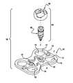
- FIG. 1is an exploded view of a fixation apparatus according to the present teachings
- FIG. 2 ais an isometric view of a fixation plate for connecting two bone portions according to the present teachings
- FIG. 2 bis a top view of a fixation plate for connecting three bone portions according to the present teachings
- FIG. 2 cis a top view of a fixation plate for connecting four bone portions according to the present teachings
- FIG. 2 dis a top view of a fixation plate for connecting five bone portions according to the present teachings
- FIG. 3is sectional view of a head member according to the present teachings
- FIG. 4is an isometric view of a head member according to the present teachings.
- FIG. 5is top view of a head member according to the present teachings.
- FIG. 6is an isometric view of a shaft member according to the present teachings.
- FIG. 7is an isometric view of another shaft member according to the present teachings.
- FIG. 8is a side view of the shaft member of FIG. 6 ;
- FIG. 9is a side view of the shaft member of FIG. 7 ;
- FIG. 10is a longitudinal sectional view of the shaft member of FIG. 8 taken along line 10 - 10 ;
- FIG. 11is a longitudinal sectional view of the shaft member of FIG. 9 taken along line 11 - 11 ;
- FIG. 12is an enlarged view of Detail D of FIGS. 8 and 9 ;
- FIG. 13is a sectional view of the Detail D of FIG. 12 along the axis 13 - 13 ;
- FIG. 14is a top view of a bone fixation fastener according to the present teachings.
- FIG. 15is a sectional view of the bone fixation fastener of FIG. 14 along axis 15 - 15 ;
- FIG. 16is sectional view of a detail of a bone fixation apparatus according to the present teachings.
- FIG. 17is an environmental view of a bone fixation system according to the present teachings shown with a tool for inserting and removing the bone fixation fasteners;
- FIG. 18is an enlarged view of the tool shown in FIG. 17 ;
- FIG. 19is a plan view of the tip of the tool shown in FIG. 18 .
- FIG. 1illustrates an exploded view of a bone fixation apparatus 100 according to the present teachings.
- the bone fixation apparatus 100generally includes a bone fixation plate 102 and a modular bone fixation fastener 104 .
- the bone fixation fastener 104includes an expandable head member 106 and a shaft member 108 having a shaft axis “C”.
- the bone fixation plate 102includes one or more fixation holes 110 through which the bone fixation fastener 104 is inserted to be affixed to a bone portion.
- FIGS. 2 a to 2 dillustrate examples of fixation plates 102 adapted for fixing together two to five bone portions 90 , respectively, such as, for example, the vertebral bodies shown in FIG. 16 .
- the fixation holes 110are arranged in pairs, two for each bone portion 90 .
- Other arrangementsare also within the scope of the present teachings.
- one fixation hole 110 for each bone portion 90may be provided, or more than two fixation holes 110 for each bone portion 90 may be provided.
- Each fixation hole 110defines an inner surface 111 , which may be spherical.
- the fixation plate 102can be shaped to conform to the bone portions 90 and have a curvature in one or two directions defined by a longitudinal axis “A” and a transverse axis “B”, as shown in FIG. 1 . It will be appreciated that the axes A and B, shown as orthogonal in FIG. 1 , need not be so limited. Additionally, the fixation plate 102 can have different shapes and it can also be planar.
- the fixation plate 102can include a viewing window 114 to help monitor the location of any graft used in the fixation procedure and the progress of fusion in post-operative X-rays and MRI scans of the bone portions 90 .
- the viewing window 114can be defined between the sets of fixation holes 110 corresponding to contiguous bone portions or vertebral bodies 90 , as shown in FIGS. 2 a -2 d .
- the fixation plate 102can include one or more anchoring holes 116 for pre-fixation anchoring or alignment using standard fasteners, such as tacks or screws or just the shaft member 108 of the fixation fastener 104 .
- the expandable head member 106is bounded by an open curved surface 118 defining a gap 120 and a central opening 122 .
- the central opening 122has an inner surface 124 , and is adapted to receive the shaft member 108 .
- the gap 120increases the resiliency of the head member 106 , such that head member 106 can expand from a relaxed position in which no pressure is exerted to the inner surface 124 , to a pressurized position in which pressure is exerted on the inner surface 124 causing the gap 120 to widen.
- the inner surface 124 of the head member 106defines an inner head cam 126 with one or more lobes 128 . Each lobe 128 of the inner head cam 126 can be constructed, for example, by offsetting a radius of a segment of the inner surface 124 by a certain radial distance and then connecting the offset regions with variable radius curves.
- FIGS. 6-13illustrate shaft members 108 according to the present teachings.
- FIGS. 7, 9 and 11depict views of a self-drilling shaft member 108
- FIGS. 6, 8 and 10depict views of a self-tapping shaft member 108 .
- the shaft member 108includes an insertion portion 130 having threads respectively adapted for self-drilling or self-tapping, and a distal portion 132 adapted to be retained by the head member 106 .
- a magnified view of the distal portion 132is illustrated as Detail D in FIG. 12 .
- a sectional view of the distal portion 132is shown in FIG. 13 .
- the distal portion 132defines a outer shaft cam 134 that has one or more lobes 136 adapted to mate with the lobes 128 of the inner head cam 126 while the head member 106 is in the relaxed position.
- the fixation fastener 104can rotate freely and be seated in the fixation plate 102 at various angles relative to the plate 102 .
- the head member 106When the head member 106 seats in the fixation hole 110 in the relaxed or unexpanded position, no pressure is exerted by the head member 106 to the inner surface 111 of the hole 110 .
- the curved surface 118 of the head member 106mates with the inner surface 111 of the fixation hole 110 , such that the head member 106 can rotate freely relative to the inner surface 111 of the fixation hole 110 in the relaxed position.
- the expanded head member 106In the pressurized or expanded position, the expanded head member 106 is expanded toward the inner surface 111 of the hole 110 .
- the head member 106has a maximum diameter “D” which, in the unexpanded position of the head member 106 , is smaller than an upper diameter “d” of the fixation hole 110 of the fixation plate, such that the head member 106 can be inserted through the fixation hole 110 .
- the upper diameter d of the fixation holeis defined in a plane generally parallel to an upper surface 161 of the fixation plate. In the expanded position, the maximum diameter D is bigger than the upper diameter d of the fixation hole 110 , preventing the head member 106 from backing out of the fixation hole 110 at the upper surface of the fixation plate.
- the expanded diameter of the head member 106is sufficiently large to press against the fixation hole 110 .
- the expanded head member 106not only prevents the head member 106 from backing out of the fixation hole 110 , but also arrests relative movement of the plate 102 and the fastener 108 . This relationship is referred to as a “constrained relationship”.
- the expanded diameter of the head member 106remains sufficiently large to prevent the head member 106 from backing out of the fixation hole, but is not so large to preclude movement between the fastener 108 and the plate 102 .
- the head member 106is permitted to articulate relative to the fixation hole 110 and thereby the fastener 108 may articulate relative to the plate 102 . This relationship is referred to as a “semi-constrained relationship”.
- the head member 106 and fastener 108may be cooperatively configured to alternatively provide both a constrained mode of operation and a semi-constrained mode of operation.
- the lobes 128 of the head member 106may cooperate with the lobes 136 of the fastener 108 to provide dual modes of operation.
- the head member 106may be rotated from a relaxed or unexpanded state through a first rotation relative to the fastener 108 to expand the head member 106 to a first expanded diameter and further rotated through a second rotation relative to the fastener 108 to expand the head member 106 to a larger second expanded diameter.
- the head member 106may be rotated in a first direction relative to the fastener (e.g., clockwise or counterclockwise) to expand the head member 106 to the smaller first expanded diameter and further rotated in an opposite second direction to expand the head member 106 to the larger second expanded diameter.
- first directionrelative to the fastener (e.g., clockwise or counterclockwise) to expand the head member 106 to the smaller first expanded diameter and further rotated in an opposite second direction to expand the head member 106 to the larger second expanded diameter.
- the fixation plate 102may be temporarily attached to the bone portions 90 with shaft members 108 or other fasteners through the anchoring holes 116 .
- Each fixation fastener 104is assembled by aligning the head member 106 with the shaft member 108 and placing the head member 106 over the shaft member 108 .
- Each fixation fastener 104seats on a countersunk portion 138 of the fixation hole 110 such that it can freely rotate, allowing the shaft member 106 to be placed in a desired orientation and be drilled or tapped into the bone portion 90 .
- the head member 106can be rotated relative to the shaft member 108 , such that the inner head cam 126 rotates out of alignment relative to the outer shaft cam 134 of the shaft member 108 , causing the head member 106 to expand, thereby locking the fixation fastener 104 to the fixation plate 102 with compression forces therebetween.
- the head member 106can include slots or other engagement formations 140 for engaging the head member 106 with a first driver 158 to rotate the head cam 126 past the shaft cam 134 and cause the head member 106 to expand against the fixation hole 110 , thereby locking the fixation fastener 104 .
- the same driver 158can be used to rotate the head member 106 in the opposite direction bringing the head and shaft cams 126 and 134 in lobe alignment to unlock the fixation fastener 104 .
- the shaft member 108can also have internal threads or other engagement formations 155 defined in an aperture 153 of the distal end 132 , such that the shaft member 108 can be fastened to and unfastened from the bone 90 with a second driver 156 that has external threads 160 shaped to be inserted in the aperture 153 and engage the internal threads 155 .
- the first and second drivers 158 and 156can be separate tools or can be combined in one tool 150 as follows.
- the first driver 158is attached to a torque handle 154 , and is hollow defining a bore 164 .
- the second driver 156is attached to a second handle 152 and passes through the bore 164 .
- the second driver 156engages the internal threads 155 of the aperture 153 of the shaft member 108 .
- the second handle 152is rotated clockwise until the fixation fastener 104 is completely inserted into the bone portion 90 and the head member 106 is level with the fixation plate 102 .
- the torque handle 154is then rotated clockwise while the first driver 158 engages the slots 140 of the head member 106 , causing the head member 106 to expand and lock the fixation fastener 104 .
- the fixation fastener 104is first unlocked by rotating the torque handle 154 counterclockwise to re-align the head cam 126 with the shaft cam 134 and return the head member to its unexpanded state, thereby loosening the fixation fastener 104 from the fixation plate 102 .
- the second handle 152is then rotated counterclockwise to remove the shaft member 108 from the bone 90 .
- fixation apparatus 100provides quick fixation and/or removal of the plate 102 to the bone portions 90 for bone repairs, while preventing the fastener 104 from backing out of the bone portions 90 after fixation.
- the fastener 104can be readily oriented in a plurality of angles relative to the plate 102 .
Landscapes
- Health & Medical Sciences (AREA)
- Orthopedic Medicine & Surgery (AREA)
- Surgery (AREA)
- Life Sciences & Earth Sciences (AREA)
- Heart & Thoracic Surgery (AREA)
- Nuclear Medicine, Radiotherapy & Molecular Imaging (AREA)
- Engineering & Computer Science (AREA)
- Biomedical Technology (AREA)
- Medical Informatics (AREA)
- Molecular Biology (AREA)
- Animal Behavior & Ethology (AREA)
- General Health & Medical Sciences (AREA)
- Public Health (AREA)
- Veterinary Medicine (AREA)
- Neurology (AREA)
- Surgical Instruments (AREA)
- Prostheses (AREA)
Abstract
Description
Claims (20)
Priority Applications (1)
| Application Number | Priority Date | Filing Date | Title |
|---|---|---|---|
| US14/254,198US10010357B2 (en) | 2004-04-08 | 2014-04-16 | Bone fixation device |
Applications Claiming Priority (3)
| Application Number | Priority Date | Filing Date | Title |
|---|---|---|---|
| US10/821,229US7942913B2 (en) | 2004-04-08 | 2004-04-08 | Bone fixation device |
| US13/088,873US8828064B2 (en) | 2004-04-08 | 2011-04-18 | Bone fixation device |
| US14/254,198US10010357B2 (en) | 2004-04-08 | 2014-04-16 | Bone fixation device |
Related Parent Applications (1)
| Application Number | Title | Priority Date | Filing Date |
|---|---|---|---|
| US13/088,873ContinuationUS8828064B2 (en) | 2004-04-08 | 2011-04-18 | Bone fixation device |
Publications (2)
| Publication Number | Publication Date |
|---|---|
| US20140228895A1 US20140228895A1 (en) | 2014-08-14 |
| US10010357B2true US10010357B2 (en) | 2018-07-03 |
Family
ID=35061553
Family Applications (3)
| Application Number | Title | Priority Date | Filing Date |
|---|---|---|---|
| US10/821,229Expired - Fee RelatedUS7942913B2 (en) | 2004-04-08 | 2004-04-08 | Bone fixation device |
| US13/088,873Expired - LifetimeUS8828064B2 (en) | 2004-04-08 | 2011-04-18 | Bone fixation device |
| US14/254,198Expired - LifetimeUS10010357B2 (en) | 2004-04-08 | 2014-04-16 | Bone fixation device |
Family Applications Before (2)
| Application Number | Title | Priority Date | Filing Date |
|---|---|---|---|
| US10/821,229Expired - Fee RelatedUS7942913B2 (en) | 2004-04-08 | 2004-04-08 | Bone fixation device |
| US13/088,873Expired - LifetimeUS8828064B2 (en) | 2004-04-08 | 2011-04-18 | Bone fixation device |
Country Status (1)
| Country | Link |
|---|---|
| US (3) | US7942913B2 (en) |
Families Citing this family (69)
| Publication number | Priority date | Publication date | Assignee | Title |
|---|---|---|---|---|
| US7575588B2 (en)* | 2003-02-03 | 2009-08-18 | Warsaw Orthopedic Inc. | Midline occipital vertebral fixation system |
| US7306605B2 (en) | 2003-10-02 | 2007-12-11 | Zimmer Spine, Inc. | Anterior cervical plate |
| US7942913B2 (en)* | 2004-04-08 | 2011-05-17 | Ebi, Llc | Bone fixation device |
| US20060025772A1 (en)* | 2004-07-30 | 2006-02-02 | Leibel David A | Bone fusion plate |
| US7854752B2 (en) | 2004-08-09 | 2010-12-21 | Theken Spine, Llc | System and method for dynamic skeletal stabilization |
| US9615866B1 (en) | 2004-10-18 | 2017-04-11 | Nuvasive, Inc. | Surgical fixation system and related methods |
| US7935137B2 (en) | 2004-12-08 | 2011-05-03 | Depuy Spine, Inc. | Locking bone screw and spinal plate system |
| US7736380B2 (en)* | 2004-12-21 | 2010-06-15 | Rhausler, Inc. | Cervical plate system |
| ES2300967T3 (en)* | 2005-03-11 | 2008-06-16 | Orthofix S.R.L. | DEVICE FOR OSTEOSYNTHESIS OF PROXIMAL FRACTURES OF THE HUMER. |
| US8262713B2 (en) | 2005-09-26 | 2012-09-11 | Depuy Spine, Inc. | Red light implant for treating osteoporosis |
| US7465313B2 (en)* | 2005-09-26 | 2008-12-16 | Depuy Spine, Inc. | Red light implant for treating degenerative disc disease |
| US9119677B2 (en) | 2005-12-09 | 2015-09-01 | DePuy Synthes Products, Inc. | Spinal plate and drill guide |
| US20070233108A1 (en)* | 2006-03-15 | 2007-10-04 | Stalcup Gregory C | Spine fixation device |
| US8025681B2 (en) | 2006-03-29 | 2011-09-27 | Theken Spine, Llc | Dynamic motion spinal stabilization system |
| US20080015592A1 (en)* | 2006-06-28 | 2008-01-17 | Depuy Products, Inc. | CAM/compression lock plate |
| US8361130B2 (en) | 2006-10-06 | 2013-01-29 | Depuy Spine, Inc. | Bone screw fixation |
| US8287575B2 (en)* | 2006-11-09 | 2012-10-16 | Stryker Trauma Gmbh | Polyaxial locking mechanism |
| US8702762B2 (en) | 2007-03-27 | 2014-04-22 | Depuy Spine, Inc. | Passive screw locking mechanism |
| EP2134279B1 (en) | 2007-04-19 | 2017-01-04 | Stryker European Holdings I, LLC | Hip fracture device with static locking mechanism allowing compression |
| US8398636B2 (en) | 2007-04-19 | 2013-03-19 | Stryker Trauma Gmbh | Hip fracture device with barrel and end cap for load control |
| EP1987792B1 (en)* | 2007-05-03 | 2011-06-22 | Medartis AG | Fixing device, combination of a fixing device with a long element, assembly with such a combination and osteosynthesis set |
| US8556944B2 (en)* | 2007-07-31 | 2013-10-15 | Stryker Spine | System and method for vertebral body plating |
| US8388666B2 (en)* | 2007-09-27 | 2013-03-05 | Biomet C.V. | Locking screw system with relatively hard spiked polyaxial bushing |
| US20090105756A1 (en) | 2007-10-23 | 2009-04-23 | Marc Richelsoph | Spinal implant |
| US8282675B2 (en)* | 2008-01-25 | 2012-10-09 | Depuy Spine, Inc. | Anti-backout mechanism |
| US20090192549A1 (en)* | 2008-01-30 | 2009-07-30 | Ebi, Llc | Bone plating system |
| FR2926975B1 (en)* | 2008-02-01 | 2010-03-26 | Alexandre Worcel | OSTEOSYNTHESIS DEVICE WITH RAPID FASTENING MEANS |
| EP2328519B1 (en)* | 2008-06-05 | 2014-12-31 | Alphatec Spine, Inc. | Modular anterior locking interbody cage |
| US9603629B2 (en) | 2008-09-09 | 2017-03-28 | Intelligent Implant Systems Llc | Polyaxial screw assembly |
| US8529609B2 (en)* | 2009-12-01 | 2013-09-10 | Osteomed Llc | Polyaxial facet fixation screw system |
| JP5662442B2 (en) | 2009-07-24 | 2015-01-28 | スパイナル・ユーエスエー・エルエルシー | Bone plate screw block system and method |
| KR20120082397A (en) | 2009-07-24 | 2012-07-23 | 스파이널 유에스에이 엘엘씨 | Bone plate system and methods of using the same |
| USD734853S1 (en) | 2009-10-14 | 2015-07-21 | Nuvasive, Inc. | Bone plate |
| US8998966B2 (en) | 2009-12-01 | 2015-04-07 | Osteomed, Llc | Polyaxial facet fixation screw system with fixation augmentation |
| US9078707B2 (en) | 2009-12-01 | 2015-07-14 | Osteomed Llc | Polyaxial facet fixation screw system with cannula inserter |
| US11793654B2 (en)* | 2010-09-03 | 2023-10-24 | Globus Medical, Inc. | Expandable fusion device and method of installation thereof |
| EP2637584A4 (en)* | 2010-10-15 | 2015-01-28 | Alphatec Holdings Inc | FIXING SCREW ASSEMBLY |
| EP2460484A1 (en)* | 2010-12-01 | 2012-06-06 | FACET-LINK Inc. | Variable angle bone screw fixation assembly |
| US9084636B2 (en)* | 2011-01-10 | 2015-07-21 | Spine Craft, LLC | Surgical plate system and method |
| US8852281B2 (en) | 2011-01-18 | 2014-10-07 | Globus Medical, Inc. | Artificial spinal disk prosthesis |
| US8940030B1 (en) | 2011-01-28 | 2015-01-27 | Nuvasive, Inc. | Spinal fixation system and related methods |
| FR2971139B1 (en)* | 2011-02-03 | 2013-02-15 | Medicrea Int | PLATE FOR THE OSTEOSYNTHESIS OF THE LOMBO-SACRED JOINT |
| US20120259367A1 (en)* | 2011-04-08 | 2012-10-11 | Kyphon Sarl | Lumbar-sacral implant allowing variable angle fixation |
| US8771324B2 (en) | 2011-05-27 | 2014-07-08 | Globus Medical, Inc. | Securing fasteners |
| US8668723B2 (en) | 2011-07-19 | 2014-03-11 | Neurostructures, Inc. | Anterior cervical plate |
| US11123117B1 (en) | 2011-11-01 | 2021-09-21 | Nuvasive, Inc. | Surgical fixation system and related methods |
| US9522023B2 (en)* | 2011-12-09 | 2016-12-20 | Zimmer Gmbh | Orthopedic plate, orthopedic device, method of coupling bone segments, and method of assembling an orthopedic plate |
| GB201207975D0 (en)* | 2012-05-08 | 2012-06-20 | Ortho Solutions Ltd | Improvements in or relating to pelvic reconstruction |
| SG11201507297QA (en)* | 2013-03-12 | 2015-10-29 | Ziptek Llc | Apparatus and method for securing tissue |
| US9522024B2 (en)* | 2013-03-12 | 2016-12-20 | Blackstone Medical, Inc. | Orthopedic plate and screw apparatus |
| US9028498B2 (en) | 2013-03-14 | 2015-05-12 | Innovasis, Inc. | Modular bone fixation plate assembly |
| US9510880B2 (en) | 2013-08-13 | 2016-12-06 | Zimmer, Inc. | Polyaxial locking mechanism |
| US9044273B2 (en)* | 2013-10-07 | 2015-06-02 | Intelligent Implant Systems, Llc | Polyaxial plate rod system and surgical procedure |
| US9629664B2 (en) | 2014-01-20 | 2017-04-25 | Neurostructures, Inc. | Anterior cervical plate |
| US9486250B2 (en) | 2014-02-20 | 2016-11-08 | Mastros Innovations, LLC. | Lateral plate |
| US9421053B2 (en)* | 2014-05-08 | 2016-08-23 | Titan Spine, Llc | Implant fixation assemblies having a screw and C-shaped fixation collar |
| US10213237B2 (en) | 2014-10-03 | 2019-02-26 | Stryker European Holdings I, Llc | Periprosthetic extension plate |
| CN104434286A (en)* | 2014-12-29 | 2015-03-25 | 北京市春立正达医疗器械股份有限公司 | Anterior cervical fixing system |
| CN104814783B (en)* | 2015-04-23 | 2018-02-27 | 济南大学 | Locked pressurized bone plate |
| US10251685B2 (en) | 2016-03-17 | 2019-04-09 | Stryker European Holdings I, Llc | Floating locking insert |
| US10512547B2 (en) | 2017-05-04 | 2019-12-24 | Neurostructures, Inc. | Interbody spacer |
| US10980641B2 (en) | 2017-05-04 | 2021-04-20 | Neurostructures, Inc. | Interbody spacer |
| EP4108194A1 (en) | 2018-03-02 | 2022-12-28 | Stryker European Holdings I, LLC | Bone plates and associated screws |
| US11076892B2 (en) | 2018-08-03 | 2021-08-03 | Neurostructures, Inc. | Anterior cervical plate |
| US11071629B2 (en) | 2018-10-13 | 2021-07-27 | Neurostructures Inc. | Interbody spacer |
| USD909580S1 (en) | 2019-04-05 | 2021-02-02 | Sunnybrook Research Institute | Surgical mesh implant |
| US11382761B2 (en) | 2020-04-11 | 2022-07-12 | Neurostructures, Inc. | Expandable interbody spacer |
| US11304817B2 (en) | 2020-06-05 | 2022-04-19 | Neurostructures, Inc. | Expandable interbody spacer |
| US11717419B2 (en) | 2020-12-10 | 2023-08-08 | Neurostructures, Inc. | Expandable interbody spacer |
Citations (132)
| Publication number | Priority date | Publication date | Assignee | Title |
|---|---|---|---|---|
| US2248054A (en) | 1939-06-07 | 1941-07-08 | Becker Joseph | Screw driver |
| US2293930A (en) | 1939-06-17 | 1942-08-25 | Groov Pin Corp | Screw |
| US2580821A (en) | 1950-10-21 | 1952-01-01 | Nicola Toufick | Spring impactor bone plate |
| US2780223A (en) | 1955-05-17 | 1957-02-05 | Paul B Haggland | Fracture plate |
| US3515418A (en)* | 1968-06-18 | 1970-06-02 | American Nucleonics Corp | Locking mechanism and telescoping assembly |
| US3741205A (en) | 1971-06-14 | 1973-06-26 | K Markolf | Bone fixation plate |
| US4279249A (en) | 1978-10-20 | 1981-07-21 | Agence Nationale De Valorisation De La Recherche (Anvar) | New prosthesis parts, their preparation and their application |
| US4388921A (en) | 1980-05-28 | 1983-06-21 | Institut Straumann Ag | Device comprising a plate and screws for fastening a plate to a bone |
| US4473068A (en) | 1982-01-18 | 1984-09-25 | Indong Oh | Trochanteric basket |
| US4484570A (en) | 1980-05-28 | 1984-11-27 | Synthes Ltd. | Device comprising an implant and screws for fastening said implant to a bone, and a device for connecting two separated pieces of bone |
| US4503848A (en) | 1981-04-08 | 1985-03-12 | Aesculap-Werke Aktiengesellschaft | Osteosynthesis plate |
| US4655203A (en) | 1983-09-20 | 1987-04-07 | Materials Consultants Oy | Bone fracture surgical device |
| US4743257A (en) | 1985-05-08 | 1988-05-10 | Materials Consultants Oy | Material for osteosynthesis devices |
| US4790703A (en) | 1987-04-24 | 1988-12-13 | Wing George S | Prevailing torque fastener assembly |
| US4903691A (en) | 1986-01-22 | 1990-02-27 | Thomas Heinl | Set of surgical instruments for joining bone fragments |
| US4905680A (en) | 1986-10-27 | 1990-03-06 | Johnson & Johnson Orthopaedics, Inc. | Absorbable bone plate |
| US5053036A (en) | 1987-11-03 | 1991-10-01 | Synthes (U.S.A.) | Point contact bone compression plate |
| US5057109A (en) | 1989-10-16 | 1991-10-15 | Sven Olerud | Fixing instruments for spinal surgery |
| US5080665A (en) | 1990-07-06 | 1992-01-14 | American Cyanamid Company | Deformable, absorbable surgical device |
| US5108399A (en) | 1988-09-17 | 1992-04-28 | Boehringer Ingelheim Gmbh | Device for osteosynthesis and process for producing it |
| US5129903A (en) | 1988-06-18 | 1992-07-14 | Luhr Hans Georg | Bone plate |
| US5139498A (en) | 1988-10-18 | 1992-08-18 | Astudillo Ley Freddy R | Device for closing sternum in heart surgery |
| US5147360A (en) | 1990-02-19 | 1992-09-15 | Societe De Fabrication De Materiel Orthopedique | Osteosynthesis device for the correction of spinal curvatures |
| US5158409A (en) | 1988-03-07 | 1992-10-27 | Eisuke Ishida | Bolt lock device |
| US5180381A (en) | 1991-09-24 | 1993-01-19 | Aust Gilbert M | Anterior lumbar/cervical bicortical compression plate |
| US5290281A (en) | 1992-06-15 | 1994-03-01 | Medicon Eg | Surgical system |
| US5346492A (en) | 1992-03-30 | 1994-09-13 | Timesh, Inc. | Perforated metallic panels and strips for internal fixation of bone fractures and for reconstructive surgery |
| US5364399A (en) | 1993-02-05 | 1994-11-15 | Danek Medical, Inc. | Anterior cervical plating system |
| US5423826A (en) | 1993-02-05 | 1995-06-13 | Danek Medical, Inc. | Anterior cervical plate holder/drill guide and method of use |
| US5468242A (en) | 1993-11-19 | 1995-11-21 | Leibinger Gmbh | Form-fitting mesh implant |
| US5520690A (en) | 1995-04-13 | 1996-05-28 | Errico; Joseph P. | Anterior spinal polyaxial locking screw plate assembly |
| US5569250A (en) | 1994-03-01 | 1996-10-29 | Sarver; David R. | Method and apparatus for securing adjacent bone portions |
| US5578034A (en) | 1995-06-07 | 1996-11-26 | Danek Medical, Inc. | Apparatus for preventing screw backout in a bone plate fixation system |
| US5578046A (en) | 1994-02-10 | 1996-11-26 | United States Surgical Corporation | Composite bioabsorbable materials and surgical articles made thereform |
| US5601553A (en) | 1994-10-03 | 1997-02-11 | Synthes (U.S.A.) | Locking plate and bone screw |
| US5607428A (en) | 1995-05-01 | 1997-03-04 | Lin; Kwan C. | Orthopedic fixation device having a double-threaded screw |
| US5676666A (en) | 1994-08-23 | 1997-10-14 | Spinetech, Inc. | Cervical spine stabilization system |
| US5681311A (en) | 1994-09-15 | 1997-10-28 | Smith & Nephew, Inc. | Osteosynthesis apparatus |
| US5690631A (en) | 1996-09-11 | 1997-11-25 | Walter Lorenz Surgical, Inc. | Multi-configurable plating system |
| US5702396A (en) | 1995-03-27 | 1997-12-30 | Hoenig; Johannes Franz | Osteosynthesis plate |
| US5704936A (en) | 1992-04-10 | 1998-01-06 | Eurosurgical | Spinal osteosynthesis device |
| US5707372A (en) | 1996-07-11 | 1998-01-13 | Third Millennium Engineering, Llc. | Multiple node variable length cross-link device |
| US5709686A (en) | 1995-03-27 | 1998-01-20 | Synthes (U.S.A.) | Bone plate |
| US5713898A (en) | 1993-05-18 | 1998-02-03 | Schafer Micomed Gmbh | Orthopedic surgical holding device |
| US5713900A (en) | 1996-05-31 | 1998-02-03 | Acromed Corporation | Apparatus for retaining bone portions in a desired spatial relationship |
| US5718705A (en) | 1996-07-16 | 1998-02-17 | Sammarco; Giacomo J. | Internal fixation plate |
| US5735853A (en) | 1994-06-17 | 1998-04-07 | Olerud; Sven | Bone screw for osteosynthesis |
| US5766176A (en) | 1996-09-11 | 1998-06-16 | Walter Lorenz Surgical, Inc. | Formable mesh |
| US5797914A (en) | 1995-12-21 | 1998-08-25 | Kls Martin, L.P. | Bone screw |
| US5800433A (en) | 1996-05-31 | 1998-09-01 | Acromed Corporation | Spinal column retaining apparatus |
| US5814048A (en) | 1996-05-03 | 1998-09-29 | Sofamor Danek Properties, Inc. | Cranioplasty plates and method of installation |
| US5843082A (en) | 1996-05-31 | 1998-12-01 | Acromed Corporation | Cervical spine stabilization method and system |
| US5904683A (en) | 1998-07-10 | 1999-05-18 | Sulzer Spine-Tech Inc. | Anterior cervical vertebral stabilizing device |
| US5925048A (en) | 1998-03-13 | 1999-07-20 | Osteomed | Bone screw |
| US5954722A (en) | 1997-07-29 | 1999-09-21 | Depuy Acromed, Inc. | Polyaxial locking plate |
| US5961524A (en) | 1998-03-11 | 1999-10-05 | Stryker Technologies Corporation | Screw and method of attachment to a substrate |
| US5980540A (en) | 1997-04-11 | 1999-11-09 | Kinamed, Inc. | Perforated cover for covering spaces in the cranium and conforming to the shape of the cranium |
| US6001101A (en) | 1994-07-05 | 1999-12-14 | Depuy France | Screw device with threaded head for permitting the coaptation of two bone fragments |
| US6019763A (en) | 1996-10-25 | 2000-02-01 | Gunze Limited | Bone joining device |
| US6039740A (en) | 1995-02-07 | 2000-03-21 | Olerud; Sven | Method and a device for implant locking |
| US6090111A (en) | 1998-06-17 | 2000-07-18 | Surgical Dynamics, Inc. | Device for securing spinal rods |
| US6117173A (en) | 1995-12-07 | 2000-09-12 | Aesculap Ag & Co., Kg | Orthopaedic fixing system |
| US6129730A (en) | 1999-02-10 | 2000-10-10 | Depuy Acromed, Inc. | Bi-fed offset pitch bone screw |
| US6147135A (en) | 1998-12-31 | 2000-11-14 | Ethicon, Inc. | Fabrication of biocompatible polymeric composites |
| US6152927A (en) | 1997-05-15 | 2000-11-28 | Sdgi Holdings, Inc. | Anterior cervical plating system |
| US6179839B1 (en) | 1999-09-20 | 2001-01-30 | Kinetikos Medical Incorporated | Bone fusion apparatus and method |
| US6193721B1 (en) | 1997-02-11 | 2001-02-27 | Gary K. Michelson | Multi-lock anterior cervical plating system |
| US6206881B1 (en) | 1995-09-06 | 2001-03-27 | Synthes (Usa) | Bone plate |
| US6206883B1 (en) | 1999-03-05 | 2001-03-27 | Stryker Technologies Corporation | Bioabsorbable materials and medical devices made therefrom |
| US6214008B1 (en) | 1997-04-16 | 2001-04-10 | White Spot Ag | Biodegradable osteosynthesis implant |
| US6221075B1 (en) | 1998-03-06 | 2001-04-24 | Bionx Implants Oy | Bioabsorbable, deformable fixation plate |
| US6228085B1 (en) | 1998-07-14 | 2001-05-08 | Theken Surgical Llc | Bone fixation system |
| US6235033B1 (en) | 2000-04-19 | 2001-05-22 | Synthes (Usa) | Bone fixation assembly |
| US6241771B1 (en) | 1997-08-13 | 2001-06-05 | Cambridge Scientific, Inc. | Resorbable interbody spinal fusion devices |
| US6258089B1 (en) | 1998-05-19 | 2001-07-10 | Alphatec Manufacturing, Inc. | Anterior cervical plate and fixation system |
| US6261291B1 (en) | 1999-07-08 | 2001-07-17 | David J. Talaber | Orthopedic implant assembly |
| US6273899B1 (en) | 1991-06-11 | 2001-08-14 | Advanced Cardiovascular Systems, Inc. | Catheter system with catheter and guidewire exchange |
| US20010014807A1 (en) | 1997-08-04 | 2001-08-16 | Erik J. Wagner | System and method for stabilizing the human spine with a bone plate |
| US6290703B1 (en) | 1996-05-13 | 2001-09-18 | Stryker France S.A. | Device for fixing the sacral bone to adjacent vertebrae during osteosynthesis of the backbone |
| US6294187B1 (en) | 1999-02-23 | 2001-09-25 | Osteotech, Inc. | Load-bearing osteoimplant, method for its manufacture and method of repairing bone using same |
| USD449692S1 (en) | 1998-02-11 | 2001-10-23 | Gary K. Michelson | Anterior cervical plate |
| US6306140B1 (en) | 2001-01-17 | 2001-10-23 | Synthes (Usa) | Bone screw |
| US6322562B1 (en) | 1998-12-19 | 2001-11-27 | Dietmar Wolter | Fixation system for bones |
| US6331179B1 (en) | 2000-01-06 | 2001-12-18 | Spinal Concepts, Inc. | System and method for stabilizing the human spine with a bone plate |
| US6342055B1 (en) | 1999-04-29 | 2002-01-29 | Theken Surgical Llc | Bone fixation system |
| US6361537B1 (en) | 2001-05-18 | 2002-03-26 | Cinci M. Anderson | Surgical plate with pawl and process for repair of a broken bone |
| US6383186B1 (en) | 1997-02-11 | 2002-05-07 | Gary K. Michelson | Single-lock skeletal plating system |
| US20020065517A1 (en) | 2000-11-28 | 2002-05-30 | Paul Kamaljit S. | Bone support assembly |
| US6402756B1 (en) | 2001-02-15 | 2002-06-11 | Third Millennium Engineering, Llc | Longitudinal plate assembly having an adjustable length |
| US6402759B1 (en) | 1998-12-11 | 2002-06-11 | Biohorizons Implant Systems, Inc. | Surgical fastener driver |
| US20020077630A1 (en) | 2000-12-19 | 2002-06-20 | Chih-I Lin | Spinal fixation and retrieval device |
| US6413259B1 (en) | 2000-12-14 | 2002-07-02 | Blackstone Medical, Inc | Bone plate assembly including a screw retaining member |
| US6423068B1 (en) | 2000-10-18 | 2002-07-23 | Erhard Reisberg | Method and apparatus for mandibular osteosynthesis |
| US6440135B2 (en) | 2000-02-01 | 2002-08-27 | Hand Innovations, Inc. | Volar fixation system with articulating stabilization pegs |
| US6440136B1 (en) | 2000-05-24 | 2002-08-27 | Medtronic Ps Medical, Inc. | Apparatus for attaching to bone |
| US20020120273A1 (en) | 1999-10-13 | 2002-08-29 | Needham Dusty Anna | Anterior cervical plating system and method |
| US20020120268A1 (en) | 2001-02-21 | 2002-08-29 | Roger Berger | Occipital plate and system for spinal stabilization |
| US20020183755A1 (en) | 2001-06-04 | 2002-12-05 | Michelson Gary K. | Dynamic anterior cervical plate system having moveable segments, instrumentation, and method for installation thereof |
| US6547790B2 (en) | 2000-08-08 | 2003-04-15 | Depuy Acromed, Inc. | Orthopaedic rod/plate locking mechanisms and surgical methods |
| US20030078583A1 (en) | 2001-10-23 | 2003-04-24 | Biedermann Motech Gmbh | Bone fixing device |
| US20030105462A1 (en) | 2001-11-30 | 2003-06-05 | Haider Thomas T. | Poly axial cervical plate system |
| US6585769B1 (en) | 1999-04-05 | 2003-07-01 | Howmedica Osteonics Corp. | Artificial spinal ligament |
| US6595993B2 (en) | 2000-05-12 | 2003-07-22 | Suler Orthopedics Ltd. | Connection of a bone screw to a bone plate |
| US6599290B2 (en) | 2001-04-17 | 2003-07-29 | Ebi, L.P. | Anterior cervical plating system and associated method |
| US20030153919A1 (en) | 2002-02-12 | 2003-08-14 | Harris Peter M. | Self-locking bone screw and implant |
| US6645208B2 (en) | 2000-11-08 | 2003-11-11 | Aesculap Ag & Co. Kg | Osteosynthesis plating apparatus and method with extension plate |
| US20030225409A1 (en) | 2002-02-01 | 2003-12-04 | Freid James M. | Spinal plate extender system and method |
| US6669701B2 (en) | 2000-01-27 | 2003-12-30 | Synthes (Usa) | Bone plate |
| US6689134B2 (en) | 2002-02-13 | 2004-02-10 | Third Millennium Engineering, Llc | Longitudinal plate assembly having an adjustable length |
| US20040039387A1 (en) | 2002-08-22 | 2004-02-26 | Larry Gause | System for stabilizing a portion of the spine |
| US20040044345A1 (en) | 2002-08-28 | 2004-03-04 | Demoss Richard Marshal | Shallow penetration bone screw |
| US6702817B2 (en) | 2001-01-19 | 2004-03-09 | Aesculap Ag & Co. Kg | Locking mechanism for a bone screw |
| US6709686B1 (en) | 2003-03-17 | 2004-03-23 | Richard G. Matthew | Potato-based food products tolerable by gluten-intolerant individuals and methods of making and using the same |
| FR2844702A1 (en) | 2002-09-24 | 2004-03-26 | Numedic | Device for fixing synthetic bone plate on bone comprises threaded rod passing through non-circular hole housing plate collar to be screwed into bone, constricted collar having non-circular external profile engaging hole |
| US20040068319A1 (en) | 2002-10-04 | 2004-04-08 | Cordaro Nicholas M. | Cervical plate/screw system for immobilizing vertebral bodies |
| US6719759B2 (en) | 1999-03-09 | 2004-04-13 | Synthes Ag Chur | Bone plate |
| US20040073218A1 (en) | 2002-10-15 | 2004-04-15 | The University Of North Carolina At Chapel Hill | Multi-angular fastening apparatus and method for surgical bone screw/plate systems |
| US6730091B1 (en) | 1999-05-03 | 2004-05-04 | Medartis Ag | Blockable bone plate |
| US20040127899A1 (en)* | 2002-12-31 | 2004-07-01 | Konieczynski David D. | Bone plate and screw system allowing bi-directional attachment |
| US20040127896A1 (en)* | 2002-10-28 | 2004-07-01 | Alan Lombardo | Bone plate assembly provided with screw locking mechanisms |
| US6761719B2 (en) | 2000-03-01 | 2004-07-13 | Sdgi Holdings, Inc. | Superelastic spinal stabilization system and method |
| US6767351B2 (en) | 2000-02-01 | 2004-07-27 | Hand Innovations, Inc. | Fixation system with multidirectional stabilization pegs |
| US6786909B1 (en) | 1999-10-27 | 2004-09-07 | Sepitec Foundation | Implant for osteosyntheses |
| US20040260291A1 (en) | 2003-06-20 | 2004-12-23 | Jensen David G. | Bone plates with intraoperatively tapped apertures |
| US20050004574A1 (en) | 2003-06-11 | 2005-01-06 | Helmut Muckter | Osteosynthesis plate or comparable implant plus ball socket |
| US20050049593A1 (en)* | 2003-09-03 | 2005-03-03 | Duong Lan Anh Nguyen | Bone plate with captive clips |
| US6893444B2 (en) | 2000-02-01 | 2005-05-17 | Hand Innovations, Llc | Bone fracture fixation systems with both multidirectional and unidirectional stabilization pegs |
| US20050143742A1 (en) | 2002-09-24 | 2005-06-30 | Stryker Trauma Sa | Device for connecting a screw to a support plate |
| US20050184265A1 (en) | 2002-06-20 | 2005-08-25 | Kazuhiro Aoki | Actuator for valve |
| EP1570796A1 (en) | 2004-03-03 | 2005-09-07 | BIEDERMANN MOTECH GmbH | Bone fixing element and stabilising device comprising one such bone fixing element |
| US20070123879A1 (en)* | 2003-02-05 | 2007-05-31 | Pioneer Laboratories, Inc. | Bone plate system |
| US7942913B2 (en) | 2004-04-08 | 2011-05-17 | Ebi, Llc | Bone fixation device |
Family Cites Families (1)
| Publication number | Priority date | Publication date | Assignee | Title |
|---|---|---|---|---|
| US6695846B2 (en)* | 2002-03-12 | 2004-02-24 | Spinal Innovations, Llc | Bone plate and screw retaining mechanism |
- 2004
- 2004-04-08USUS10/821,229patent/US7942913B2/ennot_activeExpired - Fee Related
- 2011
- 2011-04-18USUS13/088,873patent/US8828064B2/ennot_activeExpired - Lifetime
- 2014
- 2014-04-16USUS14/254,198patent/US10010357B2/ennot_activeExpired - Lifetime
Patent Citations (157)
| Publication number | Priority date | Publication date | Assignee | Title |
|---|---|---|---|---|
| US2248054A (en) | 1939-06-07 | 1941-07-08 | Becker Joseph | Screw driver |
| US2293930A (en) | 1939-06-17 | 1942-08-25 | Groov Pin Corp | Screw |
| US2580821A (en) | 1950-10-21 | 1952-01-01 | Nicola Toufick | Spring impactor bone plate |
| US2780223A (en) | 1955-05-17 | 1957-02-05 | Paul B Haggland | Fracture plate |
| US3515418A (en)* | 1968-06-18 | 1970-06-02 | American Nucleonics Corp | Locking mechanism and telescoping assembly |
| US3741205A (en) | 1971-06-14 | 1973-06-26 | K Markolf | Bone fixation plate |
| US4279249A (en) | 1978-10-20 | 1981-07-21 | Agence Nationale De Valorisation De La Recherche (Anvar) | New prosthesis parts, their preparation and their application |
| US4484570A (en) | 1980-05-28 | 1984-11-27 | Synthes Ltd. | Device comprising an implant and screws for fastening said implant to a bone, and a device for connecting two separated pieces of bone |
| US4388921A (en) | 1980-05-28 | 1983-06-21 | Institut Straumann Ag | Device comprising a plate and screws for fastening a plate to a bone |
| US4503848A (en) | 1981-04-08 | 1985-03-12 | Aesculap-Werke Aktiengesellschaft | Osteosynthesis plate |
| US4473068A (en) | 1982-01-18 | 1984-09-25 | Indong Oh | Trochanteric basket |
| US4655203A (en) | 1983-09-20 | 1987-04-07 | Materials Consultants Oy | Bone fracture surgical device |
| US4743257A (en) | 1985-05-08 | 1988-05-10 | Materials Consultants Oy | Material for osteosynthesis devices |
| US4743257C1 (en) | 1985-05-08 | 2002-05-28 | Materials Consultants Oy | Material for osteosynthesis devices |
| US4903691A (en) | 1986-01-22 | 1990-02-27 | Thomas Heinl | Set of surgical instruments for joining bone fragments |
| US4905680A (en) | 1986-10-27 | 1990-03-06 | Johnson & Johnson Orthopaedics, Inc. | Absorbable bone plate |
| US4790703A (en) | 1987-04-24 | 1988-12-13 | Wing George S | Prevailing torque fastener assembly |
| US5053036A (en) | 1987-11-03 | 1991-10-01 | Synthes (U.S.A.) | Point contact bone compression plate |
| US5158409A (en) | 1988-03-07 | 1992-10-27 | Eisuke Ishida | Bolt lock device |
| US5129903A (en) | 1988-06-18 | 1992-07-14 | Luhr Hans Georg | Bone plate |
| US5108399A (en) | 1988-09-17 | 1992-04-28 | Boehringer Ingelheim Gmbh | Device for osteosynthesis and process for producing it |
| US5139498A (en) | 1988-10-18 | 1992-08-18 | Astudillo Ley Freddy R | Device for closing sternum in heart surgery |
| US5057109A (en) | 1989-10-16 | 1991-10-15 | Sven Olerud | Fixing instruments for spinal surgery |
| US5147360A (en) | 1990-02-19 | 1992-09-15 | Societe De Fabrication De Materiel Orthopedique | Osteosynthesis device for the correction of spinal curvatures |
| US5376102A (en) | 1990-07-06 | 1994-12-27 | American Cyanamid Co. | Deformable, absorbable surgical device |
| US5080665A (en) | 1990-07-06 | 1992-01-14 | American Cyanamid Company | Deformable, absorbable surgical device |
| US6273899B1 (en) | 1991-06-11 | 2001-08-14 | Advanced Cardiovascular Systems, Inc. | Catheter system with catheter and guidewire exchange |
| US5180381A (en) | 1991-09-24 | 1993-01-19 | Aust Gilbert M | Anterior lumbar/cervical bicortical compression plate |
| US5346492A (en) | 1992-03-30 | 1994-09-13 | Timesh, Inc. | Perforated metallic panels and strips for internal fixation of bone fractures and for reconstructive surgery |
| US5704936A (en) | 1992-04-10 | 1998-01-06 | Eurosurgical | Spinal osteosynthesis device |
| US5290281A (en) | 1992-06-15 | 1994-03-01 | Medicon Eg | Surgical system |
| US5607427A (en) | 1992-06-15 | 1997-03-04 | Medicon Eg | Surgical system |
| US5423826A (en) | 1993-02-05 | 1995-06-13 | Danek Medical, Inc. | Anterior cervical plate holder/drill guide and method of use |
| US5364399A (en) | 1993-02-05 | 1994-11-15 | Danek Medical, Inc. | Anterior cervical plating system |
| US5713898A (en) | 1993-05-18 | 1998-02-03 | Schafer Micomed Gmbh | Orthopedic surgical holding device |
| US5468242A (en) | 1993-11-19 | 1995-11-21 | Leibinger Gmbh | Form-fitting mesh implant |
| US5578046A (en) | 1994-02-10 | 1996-11-26 | United States Surgical Corporation | Composite bioabsorbable materials and surgical articles made thereform |
| US5569250A (en) | 1994-03-01 | 1996-10-29 | Sarver; David R. | Method and apparatus for securing adjacent bone portions |
| US5868746A (en) | 1994-03-01 | 1999-02-09 | Biomet, Inc. | Method and apparatus for securing adjacent bone portions |
| US5735853A (en) | 1994-06-17 | 1998-04-07 | Olerud; Sven | Bone screw for osteosynthesis |
| US6001101A (en) | 1994-07-05 | 1999-12-14 | Depuy France | Screw device with threaded head for permitting the coaptation of two bone fragments |
| US5676666A (en) | 1994-08-23 | 1997-10-14 | Spinetech, Inc. | Cervical spine stabilization system |
| US5681311A (en) | 1994-09-15 | 1997-10-28 | Smith & Nephew, Inc. | Osteosynthesis apparatus |
| US5601553A (en) | 1994-10-03 | 1997-02-11 | Synthes (U.S.A.) | Locking plate and bone screw |
| US6039740A (en) | 1995-02-07 | 2000-03-21 | Olerud; Sven | Method and a device for implant locking |
| US5702396A (en) | 1995-03-27 | 1997-12-30 | Hoenig; Johannes Franz | Osteosynthesis plate |
| US5709686A (en) | 1995-03-27 | 1998-01-20 | Synthes (U.S.A.) | Bone plate |
| US5876402A (en) | 1995-04-13 | 1999-03-02 | Errico; Joseph P. | Anterior spinal polyaxial locking screw plate assembly having recessed retaining rings |
| US5520690A (en) | 1995-04-13 | 1996-05-28 | Errico; Joseph P. | Anterior spinal polyaxial locking screw plate assembly |
| US5531746A (en) | 1995-04-13 | 1996-07-02 | Fastenetix, L.L.C. | Posterior spinal polyaxial locking lateral mass screw plate assembly |
| US5607426A (en) | 1995-04-13 | 1997-03-04 | Fastenletix, L.L.C. | Threaded polyaxial locking screw plate assembly |
| US5607428A (en) | 1995-05-01 | 1997-03-04 | Lin; Kwan C. | Orthopedic fixation device having a double-threaded screw |
| US5578034A (en) | 1995-06-07 | 1996-11-26 | Danek Medical, Inc. | Apparatus for preventing screw backout in a bone plate fixation system |
| US6206881B1 (en) | 1995-09-06 | 2001-03-27 | Synthes (Usa) | Bone plate |
| US6117173A (en) | 1995-12-07 | 2000-09-12 | Aesculap Ag & Co., Kg | Orthopaedic fixing system |
| US5797914A (en) | 1995-12-21 | 1998-08-25 | Kls Martin, L.P. | Bone screw |
| US5814048A (en) | 1996-05-03 | 1998-09-29 | Sofamor Danek Properties, Inc. | Cranioplasty plates and method of installation |
| US6290703B1 (en) | 1996-05-13 | 2001-09-18 | Stryker France S.A. | Device for fixing the sacral bone to adjacent vertebrae during osteosynthesis of the backbone |
| US5713900A (en) | 1996-05-31 | 1998-02-03 | Acromed Corporation | Apparatus for retaining bone portions in a desired spatial relationship |
| US5843082A (en) | 1996-05-31 | 1998-12-01 | Acromed Corporation | Cervical spine stabilization method and system |
| US5800433A (en) | 1996-05-31 | 1998-09-01 | Acromed Corporation | Spinal column retaining apparatus |
| US6036693A (en) | 1996-05-31 | 2000-03-14 | Depuy Orthopaedics, Inc. | Cervical spine stabilization method and system |
| US5707372A (en) | 1996-07-11 | 1998-01-13 | Third Millennium Engineering, Llc. | Multiple node variable length cross-link device |
| US5718705A (en) | 1996-07-16 | 1998-02-17 | Sammarco; Giacomo J. | Internal fixation plate |
| US5766176A (en) | 1996-09-11 | 1998-06-16 | Walter Lorenz Surgical, Inc. | Formable mesh |
| US5690631A (en) | 1996-09-11 | 1997-11-25 | Walter Lorenz Surgical, Inc. | Multi-configurable plating system |
| US6019763A (en) | 1996-10-25 | 2000-02-01 | Gunze Limited | Bone joining device |
| US6193721B1 (en) | 1997-02-11 | 2001-02-27 | Gary K. Michelson | Multi-lock anterior cervical plating system |
| US6428542B1 (en) | 1997-02-11 | 2002-08-06 | Gary K. Michelson | Single-lock anterior cervical plate |
| US6916320B2 (en) | 1997-02-11 | 2005-07-12 | Gary K. Michelson | Anterior cervical plate system |
| US6620163B1 (en) | 1997-02-11 | 2003-09-16 | Gary K. Michelson | Anterior cervical plating system and bone screw |
| US6383186B1 (en) | 1997-02-11 | 2002-05-07 | Gary K. Michelson | Single-lock skeletal plating system |
| US20030018335A1 (en) | 1997-02-11 | 2003-01-23 | Michelson Gary K. | Anterior cervical plate system |
| US6398783B1 (en) | 1997-02-11 | 2002-06-04 | Sulzer Spine-Tech Inc. | Multi-lock anterior cervical plate |
| US20020045896A1 (en) | 1997-02-11 | 2002-04-18 | Michelson Gary K. | Anterior cervical plating system, instrumentation, and method of installation |
| US6416528B1 (en) | 1997-02-11 | 2002-07-09 | Gary K. Michelson | Anterior cervical plating system, instrumentation, and method of installation |
| US5980540A (en) | 1997-04-11 | 1999-11-09 | Kinamed, Inc. | Perforated cover for covering spaces in the cranium and conforming to the shape of the cranium |
| US6214008B1 (en) | 1997-04-16 | 2001-04-10 | White Spot Ag | Biodegradable osteosynthesis implant |
| US6152927A (en) | 1997-05-15 | 2000-11-28 | Sdgi Holdings, Inc. | Anterior cervical plating system |
| US5954722A (en) | 1997-07-29 | 1999-09-21 | Depuy Acromed, Inc. | Polyaxial locking plate |
| US6454769B2 (en) | 1997-08-04 | 2002-09-24 | Spinal Concepts, Inc. | System and method for stabilizing the human spine with a bone plate |
| US20020058939A1 (en) | 1997-08-04 | 2002-05-16 | Spinal Concepts, Inc. | System and method for stabilizing the human spine with a bone plate |
| US20010014807A1 (en) | 1997-08-04 | 2001-08-16 | Erik J. Wagner | System and method for stabilizing the human spine with a bone plate |
| US6241771B1 (en) | 1997-08-13 | 2001-06-05 | Cambridge Scientific, Inc. | Resorbable interbody spinal fusion devices |
| USD449692S1 (en) | 1998-02-11 | 2001-10-23 | Gary K. Michelson | Anterior cervical plate |
| US6221075B1 (en) | 1998-03-06 | 2001-04-24 | Bionx Implants Oy | Bioabsorbable, deformable fixation plate |
| US5961524A (en) | 1998-03-11 | 1999-10-05 | Stryker Technologies Corporation | Screw and method of attachment to a substrate |
| US5925048A (en) | 1998-03-13 | 1999-07-20 | Osteomed | Bone screw |
| US6258089B1 (en) | 1998-05-19 | 2001-07-10 | Alphatec Manufacturing, Inc. | Anterior cervical plate and fixation system |
| US6090111A (en) | 1998-06-17 | 2000-07-18 | Surgical Dynamics, Inc. | Device for securing spinal rods |
| US5904683A (en) | 1998-07-10 | 1999-05-18 | Sulzer Spine-Tech Inc. | Anterior cervical vertebral stabilizing device |
| US6228085B1 (en) | 1998-07-14 | 2001-05-08 | Theken Surgical Llc | Bone fixation system |
| US6402759B1 (en) | 1998-12-11 | 2002-06-11 | Biohorizons Implant Systems, Inc. | Surgical fastener driver |
| US6322562B1 (en) | 1998-12-19 | 2001-11-27 | Dietmar Wolter | Fixation system for bones |
| US6147135A (en) | 1998-12-31 | 2000-11-14 | Ethicon, Inc. | Fabrication of biocompatible polymeric composites |
| US6129730A (en) | 1999-02-10 | 2000-10-10 | Depuy Acromed, Inc. | Bi-fed offset pitch bone screw |
| US6294187B1 (en) | 1999-02-23 | 2001-09-25 | Osteotech, Inc. | Load-bearing osteoimplant, method for its manufacture and method of repairing bone using same |
| US20010012940A1 (en) | 1999-03-05 | 2001-08-09 | Tunc Deger C. | Bioabsorbable materials and medical devices made therefrom |
| US6206883B1 (en) | 1999-03-05 | 2001-03-27 | Stryker Technologies Corporation | Bioabsorbable materials and medical devices made therefrom |
| US20040181228A1 (en) | 1999-03-09 | 2004-09-16 | Synthes Ag Chur And Synthes (Usa) | Bone plante |
| US6719759B2 (en) | 1999-03-09 | 2004-04-13 | Synthes Ag Chur | Bone plate |
| US6585769B1 (en) | 1999-04-05 | 2003-07-01 | Howmedica Osteonics Corp. | Artificial spinal ligament |
| US6342055B1 (en) | 1999-04-29 | 2002-01-29 | Theken Surgical Llc | Bone fixation system |
| US6730091B1 (en) | 1999-05-03 | 2004-05-04 | Medartis Ag | Blockable bone plate |
| US6261291B1 (en) | 1999-07-08 | 2001-07-17 | David J. Talaber | Orthopedic implant assembly |
| US6179839B1 (en) | 1999-09-20 | 2001-01-30 | Kinetikos Medical Incorporated | Bone fusion apparatus and method |
| US20020120273A1 (en) | 1999-10-13 | 2002-08-29 | Needham Dusty Anna | Anterior cervical plating system and method |
| US6786909B1 (en) | 1999-10-27 | 2004-09-07 | Sepitec Foundation | Implant for osteosyntheses |
| US6331179B1 (en) | 2000-01-06 | 2001-12-18 | Spinal Concepts, Inc. | System and method for stabilizing the human spine with a bone plate |
| US6669701B2 (en) | 2000-01-27 | 2003-12-30 | Synthes (Usa) | Bone plate |
| US20040236332A1 (en) | 2000-01-27 | 2004-11-25 | Synthes Ag Chur And Synthes (Usa) | Bone plate |
| US6440135B2 (en) | 2000-02-01 | 2002-08-27 | Hand Innovations, Inc. | Volar fixation system with articulating stabilization pegs |
| US6767351B2 (en) | 2000-02-01 | 2004-07-27 | Hand Innovations, Inc. | Fixation system with multidirectional stabilization pegs |
| US6893444B2 (en) | 2000-02-01 | 2005-05-17 | Hand Innovations, Llc | Bone fracture fixation systems with both multidirectional and unidirectional stabilization pegs |
| US6761719B2 (en) | 2000-03-01 | 2004-07-13 | Sdgi Holdings, Inc. | Superelastic spinal stabilization system and method |
| US6235033B1 (en) | 2000-04-19 | 2001-05-22 | Synthes (Usa) | Bone fixation assembly |
| US6595993B2 (en) | 2000-05-12 | 2003-07-22 | Suler Orthopedics Ltd. | Connection of a bone screw to a bone plate |
| US6440136B1 (en) | 2000-05-24 | 2002-08-27 | Medtronic Ps Medical, Inc. | Apparatus for attaching to bone |
| US6547790B2 (en) | 2000-08-08 | 2003-04-15 | Depuy Acromed, Inc. | Orthopaedic rod/plate locking mechanisms and surgical methods |
| US6423068B1 (en) | 2000-10-18 | 2002-07-23 | Erhard Reisberg | Method and apparatus for mandibular osteosynthesis |
| US6645208B2 (en) | 2000-11-08 | 2003-11-11 | Aesculap Ag & Co. Kg | Osteosynthesis plating apparatus and method with extension plate |
| US20020065517A1 (en) | 2000-11-28 | 2002-05-30 | Paul Kamaljit S. | Bone support assembly |
| US6503250B2 (en) | 2000-11-28 | 2003-01-07 | Kamaljit S. Paul | Bone support assembly |
| US6413259B1 (en) | 2000-12-14 | 2002-07-02 | Blackstone Medical, Inc | Bone plate assembly including a screw retaining member |
| US6458133B1 (en) | 2000-12-19 | 2002-10-01 | Chih-I Lin | Spinal fixation and retrieval device |
| US20020077630A1 (en) | 2000-12-19 | 2002-06-20 | Chih-I Lin | Spinal fixation and retrieval device |
| US6306140B1 (en) | 2001-01-17 | 2001-10-23 | Synthes (Usa) | Bone screw |
| US6702817B2 (en) | 2001-01-19 | 2004-03-09 | Aesculap Ag & Co. Kg | Locking mechanism for a bone screw |
| US20040153092A1 (en) | 2001-01-19 | 2004-08-05 | Aesculap Ag & Co. Kg | Locking mechanism for a bone screw |
| US6402756B1 (en) | 2001-02-15 | 2002-06-11 | Third Millennium Engineering, Llc | Longitudinal plate assembly having an adjustable length |
| US20020120268A1 (en) | 2001-02-21 | 2002-08-29 | Roger Berger | Occipital plate and system for spinal stabilization |
| US6599290B2 (en) | 2001-04-17 | 2003-07-29 | Ebi, L.P. | Anterior cervical plating system and associated method |
| US6361537B1 (en) | 2001-05-18 | 2002-03-26 | Cinci M. Anderson | Surgical plate with pawl and process for repair of a broken bone |
| US20020183755A1 (en) | 2001-06-04 | 2002-12-05 | Michelson Gary K. | Dynamic anterior cervical plate system having moveable segments, instrumentation, and method for installation thereof |
| US20030078583A1 (en) | 2001-10-23 | 2003-04-24 | Biedermann Motech Gmbh | Bone fixing device |
| US20030105462A1 (en) | 2001-11-30 | 2003-06-05 | Haider Thomas T. | Poly axial cervical plate system |
| US20030225409A1 (en) | 2002-02-01 | 2003-12-04 | Freid James M. | Spinal plate extender system and method |
| US20030153919A1 (en) | 2002-02-12 | 2003-08-14 | Harris Peter M. | Self-locking bone screw and implant |
| US6689134B2 (en) | 2002-02-13 | 2004-02-10 | Third Millennium Engineering, Llc | Longitudinal plate assembly having an adjustable length |
| US20050184265A1 (en) | 2002-06-20 | 2005-08-25 | Kazuhiro Aoki | Actuator for valve |
| US20040039387A1 (en) | 2002-08-22 | 2004-02-26 | Larry Gause | System for stabilizing a portion of the spine |
| US20040044345A1 (en) | 2002-08-28 | 2004-03-04 | Demoss Richard Marshal | Shallow penetration bone screw |
| WO2004028334A2 (en) | 2002-09-24 | 2004-04-08 | Stryker Trauma Sa | Device for solidly connecting a part to a support and method of fitting one such device |
| FR2844702A1 (en) | 2002-09-24 | 2004-03-26 | Numedic | Device for fixing synthetic bone plate on bone comprises threaded rod passing through non-circular hole housing plate collar to be screwed into bone, constricted collar having non-circular external profile engaging hole |
| US20050143742A1 (en) | 2002-09-24 | 2005-06-30 | Stryker Trauma Sa | Device for connecting a screw to a support plate |
| US20040068319A1 (en) | 2002-10-04 | 2004-04-08 | Cordaro Nicholas M. | Cervical plate/screw system for immobilizing vertebral bodies |
| US20040073218A1 (en) | 2002-10-15 | 2004-04-15 | The University Of North Carolina At Chapel Hill | Multi-angular fastening apparatus and method for surgical bone screw/plate systems |
| US20040127896A1 (en)* | 2002-10-28 | 2004-07-01 | Alan Lombardo | Bone plate assembly provided with screw locking mechanisms |
| US20040127899A1 (en)* | 2002-12-31 | 2004-07-01 | Konieczynski David D. | Bone plate and screw system allowing bi-directional attachment |
| US20070123879A1 (en)* | 2003-02-05 | 2007-05-31 | Pioneer Laboratories, Inc. | Bone plate system |
| US8172885B2 (en) | 2003-02-05 | 2012-05-08 | Pioneer Surgical Technology, Inc. | Bone plate system |
| US6709686B1 (en) | 2003-03-17 | 2004-03-23 | Richard G. Matthew | Potato-based food products tolerable by gluten-intolerant individuals and methods of making and using the same |
| US20050004574A1 (en) | 2003-06-11 | 2005-01-06 | Helmut Muckter | Osteosynthesis plate or comparable implant plus ball socket |
| US20040260291A1 (en) | 2003-06-20 | 2004-12-23 | Jensen David G. | Bone plates with intraoperatively tapped apertures |
| US20050049593A1 (en)* | 2003-09-03 | 2005-03-03 | Duong Lan Anh Nguyen | Bone plate with captive clips |
| EP1570796A1 (en) | 2004-03-03 | 2005-09-07 | BIEDERMANN MOTECH GmbH | Bone fixing element and stabilising device comprising one such bone fixing element |
| US7942913B2 (en) | 2004-04-08 | 2011-05-17 | Ebi, Llc | Bone fixation device |
Non-Patent Citations (6)
| Title |
|---|
| "kink". Merriam-Webster Online Dictionary [online], [retrieved on Nov. 16, 2006]. Retrieved from the Internet <URL: www.m-w.com. cited by examiner. |
| "spherical". Merriam-Webster Online Dictionary [online], [retrieved on Nov. 16, 2006]. Retrieved from the Internet <URL: www.m-w.com. citedby examiner. |
| Advisory Action for U.S. Appl. No. 13/088,873, dated Jan. 28, 2014. |
| Final Office Action for U.S. Appl. No. 13/088,873, dated Oct. 21, 2013. |
| Non-Final Office Action for U.S. Appl. No. 13/088,873, dated May 8, 2013. |
| Non-Final Office Action for U.S. Appl. No. 13/088,873, dated Nov. 1, 2012. |
Also Published As
| Publication number | Publication date |
|---|---|
| US20140228895A1 (en) | 2014-08-14 |
| US7942913B2 (en) | 2011-05-17 |
| US8828064B2 (en) | 2014-09-09 |
| US20110196423A1 (en) | 2011-08-11 |
| US20050228386A1 (en) | 2005-10-13 |
Similar Documents
| Publication | Publication Date | Title |
|---|---|---|
| US10010357B2 (en) | Bone fixation device | |
| US11026725B2 (en) | Hybrid spinal plates | |
| US7527640B2 (en) | Bone fixation system | |
| US8734493B2 (en) | Screw locking mechanism and method | |
| US6666867B2 (en) | Longitudinal plate assembly having an adjustable length | |
| US6402756B1 (en) | Longitudinal plate assembly having an adjustable length | |
| US9364272B2 (en) | Bone fixation plate | |
| US8216284B2 (en) | Bone fixation assembly | |
| US9687282B2 (en) | Orthopedic plate having threaded holes for locking screws or pegs and non-threaded holes for a variable axis locking mechanism | |
| US6599290B2 (en) | Anterior cervical plating system and associated method | |
| US7322984B2 (en) | Spinal plate with internal screw locks | |
| US8287550B2 (en) | Bone screw retaining system | |
| AU2005269990B2 (en) | Bone plate system with bone screws fixed by secondary compression | |
| US20090171396A1 (en) | Bone fixation plate | |
| US20060106387A1 (en) | Spinal plate system and method of use | |
| US9480510B2 (en) | Devices, systems and methods of attaching same to the spine |
Legal Events
| Date | Code | Title | Description |
|---|---|---|---|
| AS | Assignment | Owner name:EBI, LLC, NEW JERSEY Free format text:ASSIGNMENT OF ASSIGNORS INTEREST;ASSIGNORS:ZIOLO, TARA;FERREIRA, RUI;SIGNING DATES FROM 20140520 TO 20140602;REEL/FRAME:033049/0562 | |
| AS | Assignment | Owner name:ZIMMER BIOMET SPINE, INC., COLORADO Free format text:ASSIGNMENT OF ASSIGNORS INTEREST;ASSIGNOR:EBI, LLC;REEL/FRAME:044712/0790 Effective date:20170621 | |
| STCF | Information on status: patent grant | Free format text:PATENTED CASE | |
| CC | Certificate of correction | ||
| MAFP | Maintenance fee payment | Free format text:PAYMENT OF MAINTENANCE FEE, 4TH YEAR, LARGE ENTITY (ORIGINAL EVENT CODE: M1551); ENTITY STATUS OF PATENT OWNER: LARGE ENTITY Year of fee payment:4 | |
| AS | Assignment | Owner name:JPMORGAN CHASE BANK, N.A., AS ADMINISTRATIVE AGENT, NEW YORK Free format text:SECURITY INTEREST;ASSIGNORS:BIOMET 3I, LLC;EBI, LLC;ZIMMER BIOMET SPINE, INC.;AND OTHERS;REEL/FRAME:059293/0213 Effective date:20220228 | |
| AS | Assignment | Owner name:CERBERUS BUSINESS FINANCE AGENCY, LLC, NEW YORK Free format text:GRANT OF A SECURITY INTEREST -- PATENTS;ASSIGNORS:ZIMMER BIOMET SPINE, LLC;EBI, LLC;REEL/FRAME:066970/0806 Effective date:20240401 | |
| AS | Assignment | Owner name:ZIMMER BIOMET SPINE, LLC (F/K/A ZIMMER BIOMET SPINE, INC.), COLORADO Free format text:RELEASE BY SECURED PARTY;ASSIGNOR:JPMORGAN CHASE BANK, N.A.;REEL/FRAME:066973/0833 Effective date:20240401 Owner name:EBI, LLC, NEW JERSEY Free format text:RELEASE BY SECURED PARTY;ASSIGNOR:JPMORGAN CHASE BANK, N.A.;REEL/FRAME:066973/0833 Effective date:20240401 | |
| AS | Assignment | Owner name:ZIMMER BIOMET SPINE, LLC, COLORADO Free format text:CHANGE OF NAME;ASSIGNOR:ZIMMER BIOMET SPINE, INC.;REEL/FRAME:069772/0121 Effective date:20240220 Owner name:HIGHRIDGE MEDICAL, LLC, COLORADO Free format text:CHANGE OF NAME;ASSIGNOR:ZIMMER BIOMET SPINE, LLC;REEL/FRAME:069772/0248 Effective date:20240405 |