US10010343B2 - Vascular access device - Google Patents
Vascular access deviceDownload PDFInfo
- Publication number
- US10010343B2 US10010343B2US15/232,144US201615232144AUS10010343B2US 10010343 B2US10010343 B2US 10010343B2US 201615232144 AUS201615232144 AUS 201615232144AUS 10010343 B2US10010343 B2US 10010343B2
- Authority
- US
- United States
- Prior art keywords
- needle
- dilator
- sheath
- access device
- inner member
- Prior art date
- Legal status (The legal status is an assumption and is not a legal conclusion. Google has not performed a legal analysis and makes no representation as to the accuracy of the status listed.)
- Active, expires
Links
Images


Classifications
- A—HUMAN NECESSITIES
- A61—MEDICAL OR VETERINARY SCIENCE; HYGIENE
- A61B—DIAGNOSIS; SURGERY; IDENTIFICATION
- A61B17/00—Surgical instruments, devices or methods
- A61B17/34—Trocars; Puncturing needles
- A61B17/3415—Trocars; Puncturing needles for introducing tubes or catheters, e.g. gastrostomy tubes, drain catheters
- A—HUMAN NECESSITIES
- A61—MEDICAL OR VETERINARY SCIENCE; HYGIENE
- A61B—DIAGNOSIS; SURGERY; IDENTIFICATION
- A61B17/00—Surgical instruments, devices or methods
- A61B17/34—Trocars; Puncturing needles
- A61B17/3498—Valves therefor, e.g. flapper valves, slide valves
- A—HUMAN NECESSITIES
- A61—MEDICAL OR VETERINARY SCIENCE; HYGIENE
- A61M—DEVICES FOR INTRODUCING MEDIA INTO, OR ONTO, THE BODY; DEVICES FOR TRANSDUCING BODY MEDIA OR FOR TAKING MEDIA FROM THE BODY; DEVICES FOR PRODUCING OR ENDING SLEEP OR STUPOR
- A61M25/00—Catheters; Hollow probes
- A61M25/0097—Catheters; Hollow probes characterised by the hub
- A—HUMAN NECESSITIES
- A61—MEDICAL OR VETERINARY SCIENCE; HYGIENE
- A61M—DEVICES FOR INTRODUCING MEDIA INTO, OR ONTO, THE BODY; DEVICES FOR TRANSDUCING BODY MEDIA OR FOR TAKING MEDIA FROM THE BODY; DEVICES FOR PRODUCING OR ENDING SLEEP OR STUPOR
- A61M25/00—Catheters; Hollow probes
- A61M25/01—Introducing, guiding, advancing, emplacing or holding catheters
- A61M25/06—Body-piercing guide needles or the like
- A61M25/0606—"Over-the-needle" catheter assemblies, e.g. I.V. catheters
- A—HUMAN NECESSITIES
- A61—MEDICAL OR VETERINARY SCIENCE; HYGIENE
- A61M—DEVICES FOR INTRODUCING MEDIA INTO, OR ONTO, THE BODY; DEVICES FOR TRANSDUCING BODY MEDIA OR FOR TAKING MEDIA FROM THE BODY; DEVICES FOR PRODUCING OR ENDING SLEEP OR STUPOR
- A61M25/00—Catheters; Hollow probes
- A61M25/01—Introducing, guiding, advancing, emplacing or holding catheters
- A61M25/06—Body-piercing guide needles or the like
- A61M25/0662—Guide tubes
- A61M25/0668—Guide tubes splittable, tear apart
- A—HUMAN NECESSITIES
- A61—MEDICAL OR VETERINARY SCIENCE; HYGIENE
- A61M—DEVICES FOR INTRODUCING MEDIA INTO, OR ONTO, THE BODY; DEVICES FOR TRANSDUCING BODY MEDIA OR FOR TAKING MEDIA FROM THE BODY; DEVICES FOR PRODUCING OR ENDING SLEEP OR STUPOR
- A61M25/00—Catheters; Hollow probes
- A61M25/01—Introducing, guiding, advancing, emplacing or holding catheters
- A61M25/06—Body-piercing guide needles or the like
- A61M25/0693—Flashback chambers
- A—HUMAN NECESSITIES
- A61—MEDICAL OR VETERINARY SCIENCE; HYGIENE
- A61M—DEVICES FOR INTRODUCING MEDIA INTO, OR ONTO, THE BODY; DEVICES FOR TRANSDUCING BODY MEDIA OR FOR TAKING MEDIA FROM THE BODY; DEVICES FOR PRODUCING OR ENDING SLEEP OR STUPOR
- A61M25/00—Catheters; Hollow probes
- A61M2025/0004—Catheters; Hollow probes having two or more concentrically arranged tubes for forming a concentric catheter system
- A61M2025/0006—Catheters; Hollow probes having two or more concentrically arranged tubes for forming a concentric catheter system which can be secured against axial movement, e.g. by using a locking cuff
- A—HUMAN NECESSITIES
- A61—MEDICAL OR VETERINARY SCIENCE; HYGIENE
- A61M—DEVICES FOR INTRODUCING MEDIA INTO, OR ONTO, THE BODY; DEVICES FOR TRANSDUCING BODY MEDIA OR FOR TAKING MEDIA FROM THE BODY; DEVICES FOR PRODUCING OR ENDING SLEEP OR STUPOR
- A61M25/00—Catheters; Hollow probes
- A61M25/01—Introducing, guiding, advancing, emplacing or holding catheters
- A61M25/06—Body-piercing guide needles or the like
- A61M25/0662—Guide tubes
- A61M2025/0681—Systems with catheter and outer tubing, e.g. sheath, sleeve or guide tube
Definitions
- the present disclosureis generally directed to access devices for introducing and/or delivering a medical article (such as, for example, a catheter, cannula, sheath, etc.) into a body space, such as, for example, an artery, vein, vessel, body cavity, or drainage site, and more specifically, to a distal tip section of such devices.
- a medical articlesuch as, for example, a catheter, cannula, sheath, etc.
- a body spacesuch as, for example, an artery, vein, vessel, body cavity, or drainage site, and more specifically, to a distal tip section of such devices.
- a catheter or vascular sheathcan be introduced into a patient's blood vessel using the Seldinger or a modified Seldinger technique.
- Seldinger or a modified Seldinger techniqueinvolve inserting an access needle into the patient's blood vessel and then inserting a guidewire through the needle and into the vessel.
- a dilator and sheath in combination or separatelyare inserted over the guidewire through tissue into the vessel.
- the needlecan be removed before or after inserting the dilator and sheath.
- the dilator and guidewireare then removed and discarded.
- the sheathcan be left in the vessel, for example, to deliver medical fluids to the patient, or a catheter or other medical article can be inserted through the sheath into the vessel to a desired location.
- Various access devices for performing the Seldinger or a modified Seldinger techniqueare known. Some access devices provide the needle, dilator, and/or sheath coaxially disposed about one another. Some such devices provide mechanisms for confirming vascular access.
- the access devices described hereinadvantageously provide improved mechanisms form confirming vascular access.
- an access device for placing a medical article within a body spaceincludes a needle, a dilator coaxially disposed about the needle, and a inner member coaxially disposed between the needle and the dilator.
- the needleincludes a fenestration near a distal end of the needle.
- a distal end of the dilatoris positioned distal to the fenestration of the needle.
- a distal end of the inner memberis positioned distal to the fenestration and proximal to the distal end of the dilator.
- a space between an outer diameter of the needle and an inner diameter of the inner memberdefines a blood flash channel in fluid communication with the fenestration to allow blood to flow from an interior of the needle through the fenestration to the blood flash channel when the needle punctures a blood vessel.
- an access device for placing a medical article within a body spaceincludes a needle, a dilator, and a inner member.
- the needleincludes a cylindrical body extending proximally along a needle lumen from a distal opening to a fenestration.
- An outer surface of the cylindrical bodyis disposed at a radius r 1 from the central longitudinal axis of the needle lumen.
- the dilatorincludes a cylindrical body extending proximally along a dilator lumen.
- An inside surface of the dilatoris disposed at a radius r 2 from the central longitudinal axis of the dilator lumen, and a portion of the cylindrical body of the dilator is configured to be disposed about the needle distal to the fenestration.
- the inner memberincludes an inner portion, an outer portion, and a dimension defined therebetween. The dimension is less than r 2 -r 1 such that the inner member can be positioned in a flash channel between the needle and the dilator.
- a sheath assemblyincludes a sheath body, a hub, and a valve including an annular member and a sealing member.
- the sheath bodyincludes a generally flexible tubular structure, a proximal end, and a distal end and defines a longitudinal axis.
- the hubis coupled with the proximal end of the sheath body, and the sheath body and hub have aligned openings forming a passage therethrough.
- the annular member of the valveis disposed against a surface of the hub facing the sheath body and includes an opening therethrough.
- the sealing member of the valvehas an engagement portion coupled with a structure of the sheath assembly disposed generally between the surface of the hub and the distal end of the sheath body.
- the sealing memberalso has a seal portion projecting into sealing engagement with the opening in the annular member in a sealing position and disposed away from the opening in the annular member in an open position.
- a sheath assemblyincludes a sheath body and hub.
- the sheath bodyincludes a generally flexible tubular structure, a proximal end, and a distal end, and defines a lumen along a longitudinal axis.
- the hubis coupled with the proximal end of the sheath body and has a passage therethrough.
- the sheath assemblyfurther includes a soft polymeric diaphragm coupled with a distal face of the hub. The diaphragm provides fluid communication between the lumen and the passage when open and has a proximal face configured to seal against a device disposed in the passage, diaphragm and lumen of the sheath assembly.
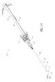
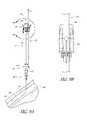
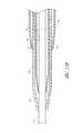
- FIG. 1Ais a perspective view of an embodiment of an access device having a pre-loaded guidewire coaxially aligned with a needle, a dilator, and a medical article such as a sheath.
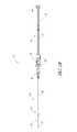
- FIG. 1Bis a plan view of the embodiment depicted in FIG. 1A .
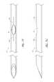
- FIG. 2Ais a plan view of the needle from FIG. 1A .
- FIG. 2Bis a side view of the needle from FIG. 1A .
- FIG. 2Cis a cross-sectional view taken along the lines 2 C- 2 C in FIG. 2A .
- FIG. 2Dis an enlarged plan view of a portion of the needle of FIG. 2A .
- FIG. 3Ais a plan view of the dilator from FIG. 1A .
- FIG. 3Bis a cross-sectional view taken along the lines 3 B- 3 B in FIG. 3A .
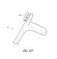
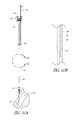
- FIG. 4Ais a plan view of the sheath from FIG. 1A and shows a sheath hub connected to a proximal end of a sheath.
- FIG. 4Bis a cross-sectional view of the sheath from FIG. 4A taken along the lines 4 B- 4 B in FIG. 4A .
- FIG. 4Cis a proximal end view of another embodiment of a sheath.
- FIG. 4Dis a plan view of the sheath of FIG. 4C .
- FIGS. 4E and 4Fare a side isometric view and an exploded side isometric view, respectively, of an embodiment of a sheath.
- FIG. 4Gis a side cross-sectional view of the sheath of FIG. 4E taken at 4 G- 4 G.
- FIGS. 4H-4Iare enlarged views of a section of the sheath of FIG. 4G showing a valve element in a closed and opened position, respectively.
- FIGS. 4J-4Lare enlarged views of a section of an embodiment of a valve element.
- FIG. 5Ais a perspective view of the guidewire section from FIG. 1A and shows a guidewire hub connected to a proximal end of a guidewire.
- FIG. 5Bis a plan view of the guidewire section of the embodiment depicted in FIG. 5A .
- FIG. 6Ais a perspective view of a track from FIG. 1A .
- FIG. 6Bis a plan view of the track in FIG. 6A and shows a locking mechanism for locking the needle relative to the dilator.
- FIG. 6Cis a side view of the track in FIG. 6B .
- FIG. 6Dan enlarged perspective view of the locking mechanism from FIG. 6B .
- FIG. 7Ais a plan view of the embodiment depicted in FIG. 1A illustrating the insertion of the distal end of the access device into a patient.
- FIG. 7Bis an enlarged view of the embodiment depicted in FIG. 8A focusing on the area of the access device adjacent to the patient.
- FIG. 7Cis an enlarged view of a portion of the embodiment depicted in FIG. 8B and illustrates a needle opening in hidden lines.
- FIG. 7Dis an enlarged cross-sectional view of a portion of the embodiment depicted in FIG. 7C and shows the needle opening or fenestration so as to allow fluid to flow from inside the needle to a channel formed between the needle and dilator.
- FIG. 7Eis an enlarged cross-sectional view of the embodiment depicted in FIG. 7C proximal to the needle opening along line 7 E- 7 E.
- FIG. 7Fis a plan view of a distal portion of another embodiment of a needle, with interior features in phantom.
- FIG. 7Gis a side view of the needle of FIG. 7F .
- FIG. 7His an enlarged cross-sectional view of the embodiment depicted in FIG. 7C distal to the needle opening along line 7 H- 7 H.
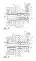
- FIG. 7Iis an enlarged cross-sectional view of another embodiment of an access device showing portions of a needle hub, a dilator hub, and an insert.
- FIG. 7Jis an enlarged cross-section view of the access device of FIG. 7I , wherein an insert is not fully inserted.
- FIG. 7Kis an enlarged view of an insert of the access device of FIG. 7I .
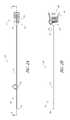
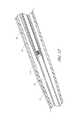
- FIG. 8Ais a side view of the embodiment depicted in FIG. 1A illustrating the guidewire advanced from the needle tip in a distal direction.
- FIG. 8Bis an enlarged view of the embodiment depicted in FIG. 8A focusing on the area where the guidewire hub is locked to the needle hub when the needle hub is in the first position.
- FIG. 9Ais a side view of the embodiment depicted in FIG. 1A illustrating the dilator and sheath being advanced distally relative to the needle body from the position illustrated in FIG. 8A .
- FIG. 9Bis an enlarged bottom view of the embodiment depicted in FIG. 9A focusing on the area where the needle hub is locked to the track when the needle hub is in the second position.
- FIG. 10Ais a side view of the embodiment depicted in FIG. 1A illustrating the removal of the guidewire, needle body, and dilator from the sheath.
- FIG. 10Bis an enlarged view of the portion of the embodiment illustrated in FIG. 10A showing the needle tip covered by the dilator during removal of the guidewire, needle body, and dilator from the sheath.
- FIG. 11Ais a partial side view of an embodiment of an access device including an inner member.
- FIG. 11Bis a partial section view of the access device of FIG. 11A .
- FIG. 12is a perspective view of an embodiment of an access device including an inner member.
- FIGS. 1A and 1Billustrate an access device 20 that can be used, for example, in performing the Seldinger or a modified Seldinger technique to introduce a catheter or sheath to a patient's blood vessel.
- the access deviceis described herein in the context of vascular access, the access device also can be used to access and place a medical article (e.g., catheter or sheath) into other locations within a patient's body (e.g., a drainage site) and for other purposes (e.g., for draining an abscess).
- a medical articlee.g., catheter or sheath
- the present embodiment of the access deviceis disclosed in the context of placing an exemplary single-piece, tubular medical article into a body space within a patient. Once placed, the tubular article can then be used to receive other medical articles (e.g., catheters, guidewires, etc.) to provide access into the body space and/or be used to provide a passage way for introducing fluids into the body space or removing (e.g., draining) fluids from the body space.
- the tubular medical articleis a sheath or catheter that is configured primarily to provide a fluid passage into a vein.
- the principles of the present inventionare not limited to the placement of single piece sheaths or catheters, or to the subsequent insertion of a medical article via the sheath or catheter.
- the access device disclosed hereinalso can be successfully utilized in connection with placing one or more other types of medical articles, including other types of sheaths, fluid drainage and delivery tubes, and single or multi-lumen catheters directly in the patient or indirectly via another medical article.
- the access devices disclosed hereincan also be configured to directly or indirectly place central venous catheters, peripherally inserted central catheters, hemodialysis catheters, surgical drainage tubes, tear-away sheaths, multi-piece sheaths, PICC lines, IV lines, scopes, as well as electrical conduit for wires or cables connected to external or implanted electronic devices or sensors.
- the medical articles listed abovemay be directly placed in the patient via the dilator, needle, and guidewire of the access device or subsequently placed within the patient via a medical article that was placed within the patient via the dilator, needle, and guidewire of the access device.
- the embodiments disclosed hereinare not limited to co-axial insertion of a single medical article.
- two cathetersmay be inserted in the patient via an inserted sheath or a second catheter may be inserted in the patient via an inserted first catheter.
- the medical article inserted via the dilator, needle, and guidewirecan form a lumen that is in addition to the lumen(s) of the subsequently inserted medical article.
- the illustration and description of the access device in connection with a sheathis merely exemplary of one possible application of the access device.
- an example embodiment of an access device 20includes a needle 22 , a dilator 24 , and a tubular sheath 26 .
- the access device 20also includes a guidewire 28 and guidewire track 30 .
- the dilator 24can be coaxially disposed about the needle 22
- the sheath 26can be coaxially disposed about the dilator 24 .
- the access device 20can be configured to allow for telescoping movement among the needle 22 , dilator 24 , and sheath 26 .
- the needle 22includes a needle body 32 and needle hub 34 .
- the needle hub 34is disposed on a proximal end of the needle body 32 at a proximal portion 52 of the needle 22 .
- the needle hub 34can include a locking structure 66 at a distal portion 61 of the needle hub 34 to allow the physician or healthcare provider to lock the needle hub 34 to a medical article such as a dilator hub 38 as described in greater detail herein.
- the needle hub 34can also include a locking structure at a proximal portion 60 of the needle hub 34 to allow the physician or healthcare provide to secure (e.g., releasably secure) another medical article to the needle hub 34 .
- the needle body 32terminates at a distal end near a distal portion 50 of the needle 22 .
- the distal end of the needle body 32can have a bevel tip 54 .
- the needle body 32has a sufficiently long length to access a targeted subcutaneous body space and has a sufficient gauge size to withstand the insertion forces when accessing the body space without causing undue trauma.
- the needle bodycan have a length between 3-20 cm, and more preferably between 3-10 cm.
- the needle body 32preferably has a length of 7 cm or greater, and more preferably has a length of 9 cm or greater, and most preferably has a length of 9 to 10 cm.
- the size of the needlepreferably is 18 gauge or smaller, and more preferably between 18-28 gauge, and most preferably between 18-26 gauge for micro-puncture applications (e.g., peripheral IVs).
- the length and gauge of the needle body 32should be significantly shorter and smaller, for example preferably between 3-4 cm and between 26-28 gauge.
- the needle 22includes an echogenic portion that can be used in combination with ultrasound to help position the needle in the desired location.
- the needle body 32includes at least one fenestration or opening 56 near a distal end of the needle body 32 .
- the fenestration 56extends, or provides a path, through the wall or side of the needle body 32 .
- the fenestration 56can allow for a fluid, such as blood, to flow into a space between a portion of the needle body 32 and a portion of the dilator 24 during use of the access device 20 , creating a “blood flash.”
- blood flashblood is observed flowing between the needle 22 and dilator 24 to indicate to the physician or healthcare provider that the tip 54 of the needle body 32 has punctured a blood vessel.
- the fenestration 56can have a variety of shapes and orientations on the needle body 32 .
- the fenestration 56 illustrated in FIG. 2Dhas an oblong shape.
- the shape of the side opening 56is not limited to the illustrated embodiment and may be round, oblong, square, or another shape.
- the dilator 24can include a dilator body 36 and dilator hub 38 .
- the dilator hub 38can include a first locking structure 78 to engage the needle hub 34 and a second locking structure 80 to engage with a sheath hub 42 , described in greater detail herein.
- optical properties, such as the color, of the needle 22 and/or the dilator 24can be selected to enhance the contrast between the blood or other fluid and the needle 22 and/or dilator 24 .
- the dilator 24can be manufactured from a clear or at least somewhat transparent material with the needle 22 having a color that contrasts with the color of the fluid.
- the needle 22can have a white or silver color to enhance its contrast with red blood.
- the sheath 26can include a sheath body 40 and sheath hub 42 .
- the sheath hub 42can include a locking structure 94 configured to engage, for example, the second locking structure 80 of the dilator hub 38 .
- the sheath body 40may be a single piece sheath through which a catheter or other medical article (e.g., a guidewire) is inserted into the vessel.
- the sheath body 40forms a conduit for insertion of the catheter or other medical article (e.g., a guidewire).
- the sheath or a portion of the sheathcan form a lumen that is in addition to the lumen(s) of the catheter.
- an equivalent to a triple lumen cathetercan be formed by inserting a dual lumen catheter through the sheath body 40 with the sheath body 40 itself forming a third lumen.
- the sheath body 40can be manufactured from a clear or at least somewhat transparent material to allow the physician or healthcare provider to see blood flowing between the needle body 32 and dilator 24 through the sheath body 40 .
- the sheathcan be a splittable sheath 26 A.
- a portion of the sheath body 40 Acan be separated or peeled-away and removed to reduce clutter at the access site.
- a peel-away sheathcan include perforations, serrations, skives, or other structures, or include other materials (e.g., PTFE with bismuth) to allow the physician or healthcare provider to remove easily a portion or the entire sheath body 40 A.
- the sheath hub 42 Amay comprise radially extending wings, handle structures, or tabs 43 to allow for easy release and removal of the sheath body 40 from other parts of the access device 20 .
- Tabs 43can have any of a number of different shapes and/or surface features to facilitate them being gripped, and are not limited to the substantially T-shape shown.
- Tabs 43are separable, to allow the splittable sheath 40 A to separate along one or more split lines, such as a predetermined split or separation line 45 .
- the split line 45can extend through either or both the sheath hub 42 A and the sheath body 40 A.
- the split line(s)can extend generally parallel to one or more longitudinal axes defined by the sheath body 40 A and/or sheath hub 42 A, but in some embodiments, the split line(s) can extend substantially non-parallel. As illustrated, splitting the sheath 26 A along the split line 45 can separate the sheath 26 A into two or more symmetrical or asymmetrical portions (e.g., halves).
- the sheath 26 Acan include similar additional features described herein for sheath 26 . In some embodiments, sheath 26 A can include similar features that are also configured to be separable into one or more portions along split line 45 .
- sheath 26 Acan have a separable lip 95 A, allowing engagement of sheath 26 A with other elements described above, such as the dilator 24 , while allowing separation along split line 45 .
- Additional embodiments of a splittable sheath body and/or hub that can be employed with sheath 26 Aare shown and described, for example, in FIGS. 23A-23B, and the corresponding supporting text (e.g., paragraphs [0223]-[0227]), of PCT International Patent Application No. PCT/US2010/034609, filed May 12, 2010, hereby incorporated by reference in its entirety herein.
- the wingsare sized to provide the healthcare provider with leverage for breaking apart the sheath hub 42 .
- the sheath hub 42 and/or the sheath body 40may comprise two or more portions (e.g. halves) connected by a thin (e.g., frangible) membrane.
- the membranecan be sized to hold the two or more portions of the sheath hub 42 and/or sheath body 40 together until the healthcare provider decides to remove the sheath hub 42 and/or sheath body 40 from the access device.
- the healthcare providermanipulates the wings to break the membrane and sever one or more portions of the sheath hub 42 into separate or partially separated pieces.
- FIGS. 4E-4Iillustrate another embodiment of a sheath that can be used with the dilators, needles, guidewires, and other elements described herein in a similar manner to the previously described sheaths is sheath 26 B.
- Sheath 26 Bcan include a sheath body 40 B and a sheath hub 42 B, with an inner cavity 241 extending through or along a portion of sheath body 40 B and/or sheath hub 42 B (e.g., along one or more longitudinal axes thereof).
- Sheath hub 42 Bcan extend from a proximal end of sheath body 40 B.
- Sheath body 40 B and/or sheath hub 42 Bcan be optionally splittable along one or more split lines 45 .
- sheath body 40 B and/or sheath hub 42 Bcan be splittable along two or more split lines 45 , to form two or more separable sections or halves, such as sheath hub sections 261 and 271 .
- the embodiments of sheath 26 B, including body 40 B and hub 42 B,can be generally similar to the embodiments of sheaths, sheath bodies, and/or sheath hubs discussed elsewhere herein.
- sheath 26 Bcan include a valve element 240 configured to substantially seal a portion of inner cavity 241 .
- Valve element 240can include a resilient plate 242 supporting a sealing element 243 .
- the resilient plate 242can be supported by a portion of the sheath body 40 B and/or hub 26 B such that a portion (e.g., a sealing portion 264 ) of the resilient plate 242 can extend (e.g., radially inwardly) into and substantially seal the inner cavity 241 .
- Valve element 240can be positioned between a proximal portion 244 of inner cavity 241 and a distal portion 245 of inner cavity 241 , such that proximal portion 244 and distal portion 245 can be substantially sealed with respect to each other.
- Portions 244 , 245can comprise any of a variety of sizes and shapes, and are shown with an approximately circular cross-sectional shape for illustrative purposes only.
- proximal portion 244 of inner cavity 241comprises at least a region having a cross-sectional area that is less than distal portion 245 , to facilitate sealing of valve 240 against portion 244 , while allowing valve 240 to flex and move distally into distal portion 241 , as described further herein.
- the valve 240can be configured to substantially inhibit flow through the inner cavity 241 in a proximal direction, while not substantially inhibiting the passage of articles such as a dilator or needle through the cavity.
- Valve element 240can be adapted to flex or move between a closed, or substantially sealed position (for example, as shown in FIGS. 4G and 4H ), and an open, or substantially unsealed position (for example, as shown in FIG. 4I ), through flexation or flexing of resilient plate 242 .
- Valve element 240can move between an open and closed position through passage of a fluid (or gas), a device, or through an operation by a user (for example, using an external lever or other device attached to resilient plate 242 ).
- a sealing surface 266 on a proximal surface of the sealing element 243can contact or otherwise engage with a corresponding sealing surface 267 on a distal surface of at least one of the splittable sheath body and hub 40 B, 42 B.
- the interaction of the sealing surfaces 266 and 267can inhibit passage through the cavity 241 in the proximal direction.
- pressure against the valve element 240 in a proximal directioncan press the sealing surfaces 266 and 267 further together.
- this mechanismcan be sufficiently resilient to withstand pressures associated with human blood vessels to prevent a loss of blood through the valve.
- the sealing element 243includes a raised portion, such as substantially dome-shaped portion 278 .
- the dome-shaped portion 278can prevent or reduce the likelihood of contact between the sealing surface 266 and a device 263 , when the device 263 is extended through cavity 241 .
- a device extended through the cavity 241for example, a dilator 24 as described herein
- the raised portion 278can prevent damage to the sealing surface 266 of the sealing element 243 by extended forceful contact with the device 263 , and thus extend the sealing capability and life of the valve element 240 .
- the resilient plate 242is configured such that the sealing surface 266 of the sealing element 243 is biased or preloaded against sealing surface 267 of the splittable sheath body and/or hub such that valve 240 is preloaded in the closed position.
- This biasingcan enhance the above-described inhibition of passage of matter in the proximal direction. Additionally, the biasing can help the valve element 240 inhibit passage of matter such as the flow of fluid or gas (e.g., blood flash, or air) or passage of a device in a distal direction (e.g., longitudinally) within cavity 241 .
- the bias towards the closed positioncan be strong enough to resist a force (or cracking pressure) in the distal direction to open the valve element 240 .
- valve element 240can be sufficient to prevent gas from being drawn distally through cavity 241 , and into a patient due to, for example, negative pressure created by a human during a normal pulse. Notably, drawing gas into a blood vessel can cause serious health effects such as an embolism.
- Resilient plate 242can comprise any of a variety of materials with sufficient rigidity to support sealing element 243 and substantially seal inner cavity 241 , and with sufficient flexibility to allow valve element 240 to flex or move between the open and closed positions described herein.
- Resilient plate 242can comprise a bio-compatible metal or plastic, or various composites or combinations thereof.
- resilient plate 242can comprise a material with reduced susceptibility to cold-setting, such that a needle, dilator, catheter, or other medical article can be extended through cavity 241 , with valve element 240 in an open position, as described above, and packaged together for a period of time within the sheath 26 B, without compromising the valve features (e.g., its flexibility and ability to seal cavity 241 when in a closed position).
- resilient plate 242can comprise, Nickel, Titanium, and/or steel (e.g., stainless steel, spring steel, etc.), or various alloys or combinations thereof.
- resilient plate 242comprises NiTi (Nitinol), or NiTi SE.
- the resilient plate 242can comprise a shape-memory alloy to facilitate its movement between an opened and closed position and to prevent cold-setting for extended periods of time such as 2 years.
- Sealing element 243can comprise any of a variety of materials that can substantially seal inner cavity 241 when in contact with or biased against sealing surface 267 .
- sealing element 243can comprise metal, plastic, rubber, or other suitable biocompatible materials such as polyisoprene, silicone, polyurethane, or other elastic polymers.
- the Shore A hardness of sealing element 243can be within a range of approximately 5 to 90, or in some embodiments, 10 to 70, or in some embodiments, approximately 15 to 50, or in some embodiments, approximately 30.
- the sealing element 243can be coated or include other surface treatments, such as a siliconized surface to facilitate low-friction sliding of various elements along its surface (such as device 263 ).
- the resilient plate 242 and the sealing element 243can be formed of the same material, such that the valve element 240 can optionally be a single unitary piece.
- Resilient plate 242 and/or element 243can be formed in a number of different ways, such as molding (e.g., injection), stamping and the like, and can be formed separately or integrally.
- Resilient plate 242 and sealing element 243can be attached to each other in a variety of ways, such as with adhesive, bonding (e.g., ultrasonic, thermal, etc.), fasteners, overmolding, and the like.
- a primer or non-stick coating or surface treatmentcan be applied to plate 242 and/or sealing element 243 to facilitate their attachment to each other during the manufacturing thereof.
- a plurality of plates 242 and/or elements 243can be formed in a single molding or stamping step, with severable tabs to allow the plates 242 and/or elements 243 to be used individually.
- the resilient plate 242can be pretreated to have certain mechanical characteristics prior to its combination with the sealing element 243 .
- the valve element 240can attach to the sheath 26 B by a variety of means. In some embodiments it can be glued or bonded to the sheath 26 B. In other embodiments, the resilient plate 242 can attach to the sheath 26 B by molding or overmoulding. In further embodiments, the resilient plate 242 can be molded integrally with the sheath 26 B (or a portion thereof such as the sheath hub half). When formed integrally, it may be desirable to give the hub 42 B or body 40 B a substantially greater thickness than the resilient plate 242 , such that the hub or body maintains a higher rigidity. In other embodiments the resilient plate 242 can attach to the sheath 26 B by a mechanical compression, such as where the sheath hub 42 B or body 40 B includes a groove that receives the plate, and allows it to be press-fit into position.
- Resilient plate 242can be attached to various portions of sheath hub 42 B and/or body 40 B.
- the sheath hub 42 B and/or body 40 Bcan comprise two or more separate pieces that are positioned and attached with respect to each other such that a portion of resilient plate 242 is clamped between a portion of sheath hub 42 B and/or body 40 B. As best shown in FIGS.
- sheath hub 42 Bcan comprise a proximal portion 48 and a distal portion 49 , configured to engage with each other such that the valve element 240 , by way of a mounting portion 265 of the resilient plate 242 , can be supported or clamped therebetween within a groove or gap 274 (as shown in FIG. 4I ).
- Portions 48 , 49can comprise any of the materials described herein generally for sheath 26 B and other components thereof, such as sheath hub 42 B and sheath body 40 B.
- portion 48comprises ABS plastic.
- portion 49comprises a K resin.
- Portions 48 , 49can engage with each other using any of a variety of attachment means and methods known or described herein, such as bonding, adhesive (e.g., solvents), and the like.
- valve element 240and resilient plate 242 , can be attached to one or more sections of sheath hub 42 B and/or body 40 B that separate along line(s) 45 .
- resilient plate 242is attached to only one separable section of sheath 26 B, such as sheath hub section 261 , to facilitate the separation of valve 240 from sheath hub section 271 during the splitting of sheath 26 B.
- plate 242can be attached to only one separable section of sheath 26 B to facilitate the flexing and movement of resilient plate 242 and sealing element 243 within inner cavity 241 .
- the valve element 240can also be separable by similar structures.
- FIGS. 4J-4Lshow further embodiments that include an annular member 268 and a resilient plate 242 A and sealing element 243 A.
- the plate 242 A and sealing element 243 Acan be similar to the resilient plate 242 and sealing element 243 shown in FIGS. 4F-4I and described herein.
- the annular member 268can function like an O-ring in some respects.
- the annular member 268includes a central bore 269 configured to receive the domed-shaped portion 278 A of the sealing element 243 A when the valve is in a closed position.
- a top surface of the annular member 268tapers so that the annular member is thinner proximate the bore 269 than at a location outward of the bore 269 , e.g., at the outer edge.
- the tapercan be downwardly from an upper surface in some embodiments.
- a bottom surface of the annular member 268can be substantially straight or flat.
- the annular member 268is placed against the sealing surface 267 so that in a closed position, the sealing element 243 A seals against the annular member 268 rather than the sealing surface 267 .
- the annular member 268can be made of a relatively soft material, and can be thin enough to tear during splitting of the sheath 26 B.
- the annular member 268can advantageously compensate for possible molding imperfections and/or misalignment in the manufacture and assembly of the sheath hub, for example, due to being constructed from a relatively soft and compliant material.
- the annular member 268also advantageously reduces the size of the aperture to be sealed by the sealing element 243 A compared to the sealing surface 267 , which can produce a greater vacuum hold to bias the sealing element 243 A in a closed position with the same spring pre-loading force of the resilient plate 242 A. Additionally, the annular member 268 can act as a seal around a device introduced into the patient through the sheath 26 B to maintain a seal when the valve 240 is in an open position to accommodate the device. The annular member 268 can therefore act as a seal independent of the sealing element 243 A. In some embodiments, the annular member 268 can stretch to accommodate and/or conform to various devices that can be introduced through the sheath 26 B.
- the sealing element 243 Acan be made of a relatively hard material, for example, polyurethane or polycarbonate.
- a relatively soft annular member 268can advantageously allow the sealing element 243 A to be made of a relatively hard material because the more compliant annular member 268 can compensate for molding imperfections, misalignment, and the like for which a relatively hard sealing element 243 A may not be able to compensate as effectively.
- the relatively hard materialcan advantageously reduce possible damage to the resilient plate 242 A.
- a sealing element 243 A made of a relatively softer material, for example, siliconethe resilient plate 242 A may bend to some extent anywhere along its length when the valve is opened.
- a sealing element 243 A made of a relatively harder materialbending of the resilient plate 242 A may be relatively more limited to a pivot axis 270 , which can reduce possible damage and/or wear to the resilient plate 242 A.
- the relatively hard materialcan also better resist tearing and/or other wear. Such tearing or wear can adversely affect the effectiveness of the seal or expose sharp portions of the resilient plate 242 A, which can cut or otherwise damage other instruments, for example a dilator 24 as described herein, inserted into and/or removed from the sheath 26 B through the valve 240 .
- the guidewire 28can include a guidewire body 44 and guidewire hub 46 .
- the guidewire hub 46can have a structure corresponding to a coupling section 290 on the guidewire track 30 , shown in FIGS. 6A-6D , to releasably connect the hub 46 to the track 30 .
- the guidewire track 30can also include a distal locking member 124 to connect the track 30 to the dilator hub 38 , and a locking mechanism 128 for the needle hub 34 .
- the access device 20can be packaged pre-assembled as shown in FIGS. 1A and 1B , with the guidewire 28 coaxially disposed within the needle 20 , the guide wire hub 46 secured to the track 30 , the needle coaxially disposed within the dilator 24 , the needle hub 34 locked to the dilator hub 38 , the guidewire track 30 attached to the dilator hub 38 , the dilator 24 coaxially disposed within the sheath 26 , and the dilator hub 38 locked to the sheath hub 42 .
- the splittable sheath 26 Ais packaged uncoupled from the remainder of the access device 20 .
- the physician or healthcare providercan insert the needle body 32 and dilator body 36 into the sheath 36 A, and advance the needle and dilator distally or the sheath proximally relative to one another until the sheath hub 42 locks to the dilator hub 38 .
- the needle body 32is inserted into a blood vessel 148 or other body site as shown in FIGS. 7A-7B .
- FIGS. 7C-7Eillustrate an embodiment of the access device at this stage of use, wherein a channel is formed between the needle and the dilator, to allow, for example, blood to flow during a blood flash.
- the needle body 32includes one or more fenestrations 56 that allow blood to flow through the sidewall of the needle body 32 and into a space between the needle body 32 and the dilator shaft 36 .
- One or more optional ridges 176can extend between the needle body 32 and the dilator shaft 36 .
- the ridges 176can define the sides of at least one channel 256 extending along a length of the needle body 32 .
- additional channels 256can be formed with additional ridges or other features.
- the ridges 176can include longitudinal gaps, to allow circumferential or transverse flow between adjacent channels formed by the ridges 176 .
- channels 256can be formed with a protruding ridge, or without a protruding ridge such as with a depression(s) or with a concentric gap.
- Channel 256can be formed with protruding ridges (as shown) or non-protruding recessed grooves or flowpaths on the inner surface of the dilator shaft 36 and/or the outer surface of the needle body 32 .
- Channel 256can be formed without protruding ridges and/or grooves, and can simply comprise the annular space formed between needle body 32 and dilator shaft 36 .
- the channel 256is depicted as straight, it can also form other patterns such as a helix or another shape wrapping about the access device. Further, where multiple channels are present they can form intersecting helices, parallel helices, or other patterns.
- a distance between the needle body 32 and a dilator shaft 36e.g. where the inner diameter of the dilator shaft exceeds the outer diameter of the needle body
- the access device 20includes features to vent the flash channel 256 .
- ventingcan be provided at least partially through an insert 51 between the dilator hub 38 and needle hub 34 , as shown in FIGS. 7I-7K .
- an additional piecesuch as the insert 51 can facilitate the provision of certain desirable dimensions, materials, and other design features that might not be otherwise possible or economical. For example, it may be desirable for a middle portion of the dilator shaft 36 to have an inner diameter substantially larger than the outer diameter of the needle body 32 near a needle fenestration.
- This difference in diameterscan create a space that allows a body fluid to flow between the two (such as in the channel 256 ) from the fenestration.
- the embodiment depicted in FIGS. 7I-7Kprovides venting with the assistance of an insert 51 .
- the insert 51can be disposed within a proximal opening 107 of the dilator hub 38 .
- the proximal opening 107can be configured to also receive a distally protruding portion 109 of the needle hub 34 .
- the insert 51can be press-fit into the dilator hub 38 , while in other embodiments it can be loosely slid onto the needle body 32 (e.g., prior to combination with the dilator).
- the insert 51defines a through-hole 101 that can slidingly receive the needle 22 (or another needle described herein), e.g. along the needle body 32 .
- the insert 51can be substantially circular, or donut-shaped, allowing flexibility in its rotational position within the dilator hub 38 .
- the insert 51can be rotationally fixed within the dilator hub 38 , i.e., with a non-circular insert and a corresponding non-circular receiving portion in the dilator hub 38 .
- the insert 51can have particular dimensions to facilitate the release of gases while hindering the release of body fluids.
- the diameter of the insert's through-hole 101can be only slightly greater than the outer diameter of the needle body 32 , creating a space or gap (not shown) between insert 51 and needle body 32 , the gap sized to allow the release of gases but hinder the release of a body fluid.
- the gasescan then flow proximally within the gap between insert 51 and needle body 32 and enter a space 107 , 108 between the needle hub 34 and the insert 51 within the receiving portion or opening 107 of the dilator hub 38 .
- the gasescan then proceed to the ambient atmosphere in a passage 111 defined between the needle hub 34 and the dilator hub 38 .
- the needle hub 34 and the dilator hub 38can connect via a luer connection that may prevent the passage of gases
- additional mechanisms known in the art or described hereincan also attach the two hubs.
- the needle hub 34can include latch element 66 that can releasably hook to a ledge portion or lip 77 of the dilator hub 38 .
- components that might otherwise form a luer connection between the two hubscan also be sufficiently separated to allow the escape of gases without compromising a connection between the hubs.
- the outer edge of the insert 51can be shaped to substantially match the receiving portion of the receiving portion of the dilator hub 38 to form a seal between the two that at least hinders the escape of a body fluid therethrough.
- a taper 105 within the dilator hub 38(also used for a luer connection with a needle, as discussed above) can facilitate a seal between the insert 51 and the dilator hub.
- the seal between the outer edge of the insert 51 and the receiving portion 107 of the dilator hub 38can also be impermeable to gases, forcing their passage through the through-hole 101 , as described above.
- the insert 51can also include a proximally projecting portion depicted as a ridge 103 along its proximal face, which can be of particular relevance as shown in FIG. 7J .
- a proximally projecting portiondepicted as a ridge 103 along its proximal face, which can be of particular relevance as shown in FIG. 7J .
- the insert 51may not completely insert into the dilator hub 38 , leaving a gap 106 between the insert 51 and a distal portion of dilator hub 38 within opening 107 , as depicted in FIG. 7J .
- Gap 106could allow the insert 51 to come into contact with the needle hub 34 , potentially forming a seal, preventing the escape of gases through the insert's through-hole 101 .
- the insertcan also include a ridge 103 with one or more grooves 104 .
- the needle hub 34can contact the ridge 103 before contacting the rest of the proximal end of the insert 51 , preserving a space therebetween.
- the one or more grooves 104provide an opening or channel in the ridge 103 for gases to pass through, to the passage 111 between the hubs 34 , 38 .
- more than one groovecan be provided to advantageously allow gases to pass through in multiple directions. Thus, if sealing contact between the insert 51 and the needle hub 34 is made on one side, gases can still escape on the other side.
- the blood flash channel 256can have various thicknesses and span angles.
- the thickness of the channel 256can vary depending on the dimensions of the needle 22 and dilator 24 .
- the channel 256can have a span angle ⁇ about the axis of the dilator 24 of about 30 degrees to about 210 degrees or more, but preferably less than 360 degrees. More preferably, the channel 256 can have a span angle ⁇ of about 60 to 150. In the illustrated embodiment, the channel 256 spans 120 degrees.
- the thickness and span angle ⁇can be chosen so as to optimize the capillary action that occurs within the channel 256 as fluid (e.g., whole blood) enters the channel 256 as may further be selected based on the expected pressure in the body cavity and viscosity of the liquid.
- the shape of the channel 256 described above and the resulting capillary actionwere optimized for use with whole blood as opposed to other fluids having a different viscosity than whole blood (e.g. leukocytes, pus, urine, plasma).
- the shape of the channel 256is not limited to the disclosed shape and may be optimized for draining other liquids, such as pus.
- the shape of the channel 256 described abovewas optimized for peripherally located vessels where the pressure in the vessel enhances the capillary action and resulting blood flash as well as for vessels located in the regions where the pressure may be low. For example, in the thorax region of the body, the expected pressure in the veins may be lower than in a peripherally located vein when the patient breathes.
- a different size of the channel for use of the access device 20 in other regions of the bodymay be employed taking into account the expected pressure within the vessel or body cavity.
- the dilator shaft 36is coaxially positioned to minimize an annular space 157 between the needle body 32 and the dilator shaft 36 while still allowing relative movement of the needle body 32 and the dilator shaft 36 .
- the inner surface 152 of the dilator shaft 36need not, though it can, lie directly against the outer-surface 154 of the needle body 32 .
- the annular interface 157 between the outer-surface 154 of the needle body 32 and the inner surface 152 of the sheath dilator shaft 36may be reduced in this region to inhibit the distal flow of blood or its constituents (or other fluids) from the opening 56 in the needle body 32 .
- the guidewire 44is inserted into the vessel 148 by advancing the guidewire hub 46 distally until the guidewire hub 46 locks to the needle hub 34 .
- the dilator body 36 and sheath body 40are inserted into the vessel 148 by releasing the dilator hub 38 from the needle hub 34 and advancing the dilator 24 and sheath 26 distally relative to the needle hub 34 along the guidewire and needle as shown in FIGS. 9A-9B .
- the guidewire track 30also advances distally with the dilator hub 38 , and the needle hub 34 locks to the locking mechanism 128 of the track 30 , preventing further movement of the needle hub 34 .
- the guidewire 44 and dilator body 36are removed from the vessel 148 leaving the sheath body 40 properly inserted within the vessel 148 .
- a larger flash channel 256(e.g., one associated with a larger French dilator) can result in a slower blood flash because blood entering the channel 256 has a larger volume to fill before traveling proximally along the outer surface of the needle.
- Various parameterscan affect the size of the flash channel 256 and speed of the blood flash.
- a physician or healthcare professionalmay want to place a relatively large sheath 26 in the vessel 148 in certain circumstances, for example, to deliver a large volume of fluid rapidly, to introduce other devices or instruments into the vessel 148 via the sheath 26 (e.g., introduce a Central Vascular Catheter (CVC)), to remove fluid or specimens from the vessel 148 , or various other reasons. Therefore, some access devices 20 include a relatively larger sheath 26 and therefore a relatively larger dilator 24 , which can result in a larger flash channel 256 for a given size of needle.
- CVCCentral Vascular Catheter
- a distance d 1 between an outer diameter of the needle body 32 and an inner diameter of the dilator 24can be about 0.025 inches (in.).
- the dimension d 1 of this magnitudecorresponds to a larger than conventional cross-sectional surface area which can result in a blood flash that is slower than desired.
- the access device 20can include an inner member 90 , that is coaxially disposed between the needle body 32 and dilator shaft 36 , for example as shown in FIGS. 11A and 11B , and that displaces blood or other body fluids between the needle body 32 and the dilator shaft 36 .
- a distal end of the inner member 90is proximal to a distal end of the dilator shaft 36 , but distal to the fenestration 56 in the needle body 32 .
- the inner member 90can be positioned coaxially with the dilator shaft 36 .
- the inner member 90can occupy some of the volume defined between the inner surface of the dilator 36 and the outer surface of the needle body 32 .
- the inner member 90reduces the free volume between these components to expedite the flash and, in some embodiments, defines a smaller flash volume between the needle body 32 and the inner member 90 .
- the inner member 90can reduce and in some cases minimize an annular space between the needle body 32 and the inner member 90 .
- An inner surface of a distal end portion of the inner member 90need not, though it can, lie directly against the outer surface of the needle body 32 .
- the distal end of the inner member 90defines an orifice through which the needle body 32 passes in a manner of slip fit or slight interference fit.
- An annular interface between the outer surface of the needle body 32 and the inner surface of the inner member 90may be reduced in this region to inhibit the distal flow of blood or its constituents (or other fluids) from the opening 56 in the needle body 32 .
- the flash channel 256is formed between the needle body 32 and the inner member 90 rather than between the needle body 32 and an inner surface of the dilator shaft 36 , thereby reducing the cross-sectional area of, e.g., the dimension of, the flash channel 256 from d 1 to d 2 as indicated in FIG. 11B .
- the inner member 90can reduce the thickness of the flash channel 256 to about one half or less than about one half, for example, about one fifth, about one tenth, or less than one tenth, of the thickness of the flash channel 256 without the inner member 90 .
- the presence of the inner member 90can reduce the thickness of the flash channel 256 from about 0.025 in. to between about 0.003 in. and about 0.005 in.
- the distal end of the inner member 90is proximal to both the distal end of the dilator shaft 36 and to the fenestration 56 in the needle body 32 so that the fenestration 56 is between the distal end of the inner member 90 and the distal end of the dilator shaft 36 , for example as shown in FIG. 12 .
- the flash channel 256is formed between the inner member 90 and the dilator 24 .
- an access device including the inner member 90can also include an insert 51 as described herein.
- the insert 51can allow for easier assembly of the access device, help keep the inner member 90 in place, provide venting of the space between the needle body 32 and the inner member 90 and/or the space between the inner member 90 and the dilator shaft 36 , and/or help prevent blood from passing proximally out of the flash channel 256 .
- the space between the inner member 90 and the dilator shaft 36can be, but need not be, in communication with the space between the inner member 90 and the needle body 32 . Communication between these spaces can be accomplished in a number of ways.
- a proximal end of the inner member 90can have a bias cut edge 92 , and the long point of the bias cut edge can abut the insert 51 when the insert 51 is fully seated in the dilator hub 38 , as shown in FIG. 7I .
- the bias cutleaves a gap 96 between the remainder of the proximal edge of the inner member 90 and the insert 51 to advantageously allow venting of the flash channel 256 between the needle body 32 and inner member 90 .
- one or more spacer or standoff memberscan be disposed between portions of the proximal end of the inner member 90 and the insert 51 to maintain one or more gaps to allow for venting.
- the spacer or standoff member(s)can be separate from or integrally formed with one or both of the inner member 90 and insert 51 .
- the proximal edge of the inner member 90fully abuts and/or is integral with the insert 51 .
- the inner member 90includes one or more fenestrations and/or reliefs to provide fluid communication.
- the access devicecan be assembled by sliding the insert 51 onto the needle body 32 , inserting the needle body 32 into the inner member 90 , and inserting the combination of the needle body 32 and the inner member 90 into the dilator 24 .
- a proximal portion of the inner member 90can extend into the dilator hub 38 when assembled as shown in FIGS. 7I and 7J .
- the inner memberlies within the dilator shaft 36 with its distal end fit onto the needle body 32 .
- the distal end of the dilator body 36prevents distal movement of the inner member 90 beyond the dilator 24 .
- the insert 51prevents proximal movement of the inner member 90 beyond the dilator 24 .
Landscapes
- Health & Medical Sciences (AREA)
- Life Sciences & Earth Sciences (AREA)
- Animal Behavior & Ethology (AREA)
- Veterinary Medicine (AREA)
- Public Health (AREA)
- Engineering & Computer Science (AREA)
- Biomedical Technology (AREA)
- Heart & Thoracic Surgery (AREA)
- General Health & Medical Sciences (AREA)
- Anesthesiology (AREA)
- Hematology (AREA)
- Pulmonology (AREA)
- Biophysics (AREA)
- Surgery (AREA)
- Pathology (AREA)
- Nuclear Medicine, Radiotherapy & Molecular Imaging (AREA)
- Medical Informatics (AREA)
- Molecular Biology (AREA)
- Gastroenterology & Hepatology (AREA)
- Media Introduction/Drainage Providing Device (AREA)
- Surgical Instruments (AREA)
Abstract
Description
Claims (11)
Priority Applications (3)
| Application Number | Priority Date | Filing Date | Title |
|---|---|---|---|
| US15/232,144US10010343B2 (en) | 2013-03-15 | 2016-08-09 | Vascular access device |
| US15/995,512US10682157B2 (en) | 2013-03-15 | 2018-06-01 | Vascular access device |
| US16/868,864US20200315656A1 (en) | 2013-03-15 | 2020-05-07 | Vascular access device |
Applications Claiming Priority (3)
| Application Number | Priority Date | Filing Date | Title |
|---|---|---|---|
| US201361799992P | 2013-03-15 | 2013-03-15 | |
| US14/207,120US9566087B2 (en) | 2013-03-15 | 2014-03-12 | Vascular access device |
| US15/232,144US10010343B2 (en) | 2013-03-15 | 2016-08-09 | Vascular access device |
Related Parent Applications (1)
| Application Number | Title | Priority Date | Filing Date |
|---|---|---|---|
| US14/207,120DivisionUS9566087B2 (en) | 2013-03-15 | 2014-03-12 | Vascular access device |
Related Child Applications (1)
| Application Number | Title | Priority Date | Filing Date |
|---|---|---|---|
| US15/995,512ContinuationUS10682157B2 (en) | 2013-03-15 | 2018-06-01 | Vascular access device |
Publications (2)
| Publication Number | Publication Date |
|---|---|
| US20170035459A1 US20170035459A1 (en) | 2017-02-09 |
| US10010343B2true US10010343B2 (en) | 2018-07-03 |
Family
ID=51530713
Family Applications (4)
| Application Number | Title | Priority Date | Filing Date |
|---|---|---|---|
| US14/207,120ActiveUS9566087B2 (en) | 2013-03-15 | 2014-03-12 | Vascular access device |
| US15/232,144Active2034-06-17US10010343B2 (en) | 2013-03-15 | 2016-08-09 | Vascular access device |
| US15/995,512Active2034-06-30US10682157B2 (en) | 2013-03-15 | 2018-06-01 | Vascular access device |
| US16/868,864AbandonedUS20200315656A1 (en) | 2013-03-15 | 2020-05-07 | Vascular access device |
Family Applications Before (1)
| Application Number | Title | Priority Date | Filing Date |
|---|---|---|---|
| US14/207,120ActiveUS9566087B2 (en) | 2013-03-15 | 2014-03-12 | Vascular access device |
Family Applications After (2)
| Application Number | Title | Priority Date | Filing Date |
|---|---|---|---|
| US15/995,512Active2034-06-30US10682157B2 (en) | 2013-03-15 | 2018-06-01 | Vascular access device |
| US16/868,864AbandonedUS20200315656A1 (en) | 2013-03-15 | 2020-05-07 | Vascular access device |
Country Status (4)
| Country | Link |
|---|---|
| US (4) | US9566087B2 (en) |
| EP (2) | EP2967628B1 (en) |
| JP (3) | JP6389235B2 (en) |
| WO (1) | WO2014152005A2 (en) |
Cited By (16)
| Publication number | Priority date | Publication date | Assignee | Title |
|---|---|---|---|---|
| USD857194S1 (en)* | 2017-01-25 | 2019-08-20 | Becton, Dickinson And Company | Needle tip shield |
| US10675446B2 (en) | 2012-03-14 | 2020-06-09 | Asspv, Llc | Flexible medical article and method of making the same |
| US10682157B2 (en) | 2013-03-15 | 2020-06-16 | Asspv, Llc | Vascular access device |
| US10849651B2 (en) | 2010-02-08 | 2020-12-01 | Smiths Medical Asd, Inc. | Access device |
| USD904625S1 (en) | 2020-05-08 | 2020-12-08 | Smiths Medical Asd, Inc. | Device for trimming a medical article |
| US10864353B2 (en) | 2011-08-17 | 2020-12-15 | Smiths Medical Asd, Inc. | Access device with valve |
| US11027099B2 (en) | 2015-04-30 | 2021-06-08 | Smiths Medical Asd, Inc. | Vascular access device |
| US11318286B2 (en) | 2020-03-23 | 2022-05-03 | I-V Access Technology, Inc. | Catheter needle assembly with enclosable needle |
| US11439476B2 (en)* | 2016-08-30 | 2022-09-13 | Gyrus Acmi, Inc. | Medical device handle lock |
| US11607525B1 (en) | 2022-06-30 | 2023-03-21 | I-V Access Technology, Inc. | Methods and devices for vascular access |
| US11738179B2 (en) | 2018-03-01 | 2023-08-29 | Smiths Medical Asd, Inc. | Guidewire retention device |
| US11839735B2 (en) | 2017-04-14 | 2023-12-12 | Smiths Medical Asd, Inc. | Vascular access device |
| US11992634B2 (en) | 2020-03-10 | 2024-05-28 | Merit Medical Systems, Inc. | Arterial access needle with proximal port |
| US12186496B2 (en) | 2017-05-26 | 2025-01-07 | Avia Vascular, Llc | Catheter delivery devices, systems, and methods |
| US12239814B2 (en) | 2017-08-31 | 2025-03-04 | I-V Access Technology, Inc. | Methods and devices for vascular access |
| US12246149B2 (en) | 2019-04-12 | 2025-03-11 | Teleflex Medical Incorporated | Catheter insertion apparatus with continuous visible flashback |
Families Citing this family (60)
| Publication number | Priority date | Publication date | Assignee | Title |
|---|---|---|---|---|
| EP1907042B1 (en) | 2005-07-06 | 2009-03-11 | Vascular Pathways Inc. | Intravenous catheter insertion device and method of use |
| US9950139B2 (en) | 2010-05-14 | 2018-04-24 | C. R. Bard, Inc. | Catheter placement device including guidewire and catheter control elements |
| US9872971B2 (en) | 2010-05-14 | 2018-01-23 | C. R. Bard, Inc. | Guidewire extension system for a catheter placement device |
| US11925779B2 (en) | 2010-05-14 | 2024-03-12 | C. R. Bard, Inc. | Catheter insertion device including top-mounted advancement components |
| US10384039B2 (en) | 2010-05-14 | 2019-08-20 | C. R. Bard, Inc. | Catheter insertion device including top-mounted advancement components |
| US8690833B2 (en) | 2011-01-31 | 2014-04-08 | Vascular Pathways, Inc. | Intravenous catheter and insertion device with reduced blood spatter |
| ES2835652T3 (en) | 2011-02-25 | 2021-06-22 | Bard Inc C R | Medical component insertion device including a retractable needle |
| US9981113B2 (en) | 2012-03-14 | 2018-05-29 | Access Scientific, Llc | Flexible medical article and method of making the same |
| WO2015148478A1 (en)* | 2014-03-24 | 2015-10-01 | Georgia Tech Research Corporation | Splittable needle |
| WO2016037127A1 (en) | 2014-09-05 | 2016-03-10 | C.R. Bard, Inc. | Catheter insertion device including retractable needle |
| EP3042684A1 (en)* | 2015-01-07 | 2016-07-13 | Abiomed Europe GmbH | Introducer set |
| ES2764218T3 (en) | 2015-01-07 | 2020-06-02 | Abiomed Europe Gmbh | Introductory cover |
| ES2975734T3 (en) | 2015-01-29 | 2024-07-12 | Becton Dickinson Co | Integrated Quick Insert Catheter |
| CA2976805C (en)* | 2015-02-23 | 2020-04-07 | C.R. Bard, Inc. | Access system |
| USD903100S1 (en) | 2015-05-01 | 2020-11-24 | C. R. Bard, Inc. | Catheter placement device |
| CN113350614A (en) | 2015-05-15 | 2021-09-07 | C·R·巴德股份有限公司 | Catheter placement device including extendable needle safety feature |
| DE102015117923A1 (en)* | 2015-07-29 | 2017-02-02 | Jens Ebnet | Puncture system |
| JP6462542B2 (en)* | 2015-09-15 | 2019-01-30 | 朝日インテック株式会社 | Balloon catheter |
| WO2017118948A1 (en)* | 2016-01-07 | 2017-07-13 | Baylis Medical Company Inc. | Hybrid transseptal dilator and methods of using the same |
| WO2017147103A1 (en) | 2016-02-22 | 2017-08-31 | Abiomed, Inc. | Introducer sheath having a multi-layer hub |
| WO2017211493A1 (en)* | 2016-06-10 | 2017-12-14 | Fresenius Kabi Deutschland Gmbh | Cannulation device |
| US10493262B2 (en) | 2016-09-12 | 2019-12-03 | C. R. Bard, Inc. | Blood control for a catheter insertion device |
| WO2018053148A1 (en) | 2016-09-14 | 2018-03-22 | Boston Scientific Scimed, Inc | Catheter hubs |
| EP3295983A1 (en)* | 2016-09-20 | 2018-03-21 | Imds R&D Bv | Trapping catheter and kit and method for preparing a trapping catheter |
| CN107374782B (en)* | 2016-10-20 | 2023-04-18 | 上海微创心通医疗科技有限公司 | Implant delivery device |
| AU2017373953B2 (en) | 2016-12-08 | 2023-05-11 | Abiomed, Inc. | Overmold technique for peel-away introducer design |
| EP3585471B1 (en) | 2017-03-01 | 2025-01-01 | C. R. Bard, Inc. | Catheter insertion device |
| DK3592411T3 (en) | 2017-03-10 | 2022-01-10 | Abiomed Inc | EXTENSIVE IMPORT DECORATIONS FOR MEDICAL DECORATION |
| US10406326B2 (en) | 2017-08-31 | 2019-09-10 | I-V Access Technology, Inc. | Methods and devices for vascular access |
| ES2980192T3 (en) | 2018-03-07 | 2024-09-30 | Bard Access Systems Inc | Guidewire advancement and blood reflux systems for a medical device insertion system |
| ES2991910T3 (en) | 2018-05-16 | 2024-12-05 | Abiomed Inc | Removable cover set |
| WO2020010478A1 (en)* | 2018-07-12 | 2020-01-16 | Rebolledo Berrios Hernan | Puncture device for accessing the vascular system |
| USD921884S1 (en) | 2018-07-27 | 2021-06-08 | Bard Access Systems, Inc. | Catheter insertion device |
| US20220184348A1 (en)* | 2019-03-14 | 2022-06-16 | St. Jude Medical, Cardiology Division, Inc. | Splittable sheath |
| CA3151126A1 (en) | 2019-08-19 | 2021-02-25 | Becton, Dickinson And Company | Midline catheter placement device |
| CN211856471U (en) | 2019-08-22 | 2020-11-03 | 贝克顿·迪金森公司 | Quantitative testing system for echogenicity of echogenic medical instrument |
| CN211884905U (en) | 2019-08-22 | 2020-11-10 | 贝克顿·迪金森公司 | Balloon dilatation catheter and balloon thereof |
| CN112401971B (en) | 2019-08-23 | 2025-09-09 | 贝克顿·迪金森公司 | Stone extraction for percutaneous nephroscope surgical design kit |
| US11890429B2 (en) | 2019-09-10 | 2024-02-06 | Bard Access Systems, Inc. | Rapidly inserted central catheter and methods thereof |
| US11559666B2 (en)* | 2019-09-17 | 2023-01-24 | Becton, Dickinson And Company | Blood collection devices, systems, and methods facilitating blood flashback |
| BR112022005254A2 (en) | 2019-09-24 | 2022-06-14 | Bard Access Systems Inc | Acute central venous catheter and peripherally inserted venous catheter integrated |
| CA3160029A1 (en)* | 2019-10-09 | 2021-04-15 | Steven R. Bacich | Apparatus and method for everting catheter for iud delivery and placement in the uterine cavity |
| WO2021081434A1 (en) | 2019-10-25 | 2021-04-29 | Bard Access Systems, Inc. | Guidewire-management devices and methods thereof |
| WO2021130649A1 (en)* | 2019-12-24 | 2021-07-01 | Poly Medicure Limited | Intravenous catheter apparatus |
| CA3168492A1 (en) | 2020-01-23 | 2021-07-29 | Bard Access Systems, Inc. | Splitable catheter docking station system |
| CA3165493A1 (en) | 2020-02-03 | 2021-08-12 | Christopher N. KORKUCH | Expandable sheath with interlock dilator |
| CN113384798A (en) | 2020-03-13 | 2021-09-14 | 巴德阿克塞斯系统股份有限公司 | Guide wire management device and method thereof |
| KR20220153062A (en) | 2020-03-13 | 2022-11-17 | 바드 액세스 시스템즈, 인크. | GUIDEWIRE-MANAGEMENT DEVICES AND METHODS THEREOF |
| EP4135819A1 (en) | 2020-04-23 | 2023-02-22 | Bard Access Systems, Inc. | Rapidly insertable central catheters including catheter assemblies |
| WO2021236950A1 (en) | 2020-05-21 | 2021-11-25 | Bard Access Systems, Inc. | Rapidly insertable central catheters including catheter assemblies |
| US20230181244A1 (en)* | 2020-06-18 | 2023-06-15 | Boston Scientific Medical Device Limited | Support assembly for flexible medical assembly |
| AU2021303150B2 (en) | 2020-06-29 | 2025-10-02 | Bard Access Systems, Inc. | Rapidly insertable central catheters including catheter assemblies and methods thereof |
| CA3186461A1 (en)* | 2020-06-29 | 2022-01-06 | Bard Access Systems, Inc. | Rapidly insertable central catheters including assemblies |
| AU2021371314B2 (en) | 2020-10-28 | 2025-09-25 | Bard Access Systems, Inc. | Catheter placement system with stiffening system |
| AU2021400331B2 (en) | 2020-12-17 | 2025-09-25 | Bard Access Systems, Inc. | Rapidly insertable central catheters and assemblies |
| EP4259254A1 (en) | 2020-12-21 | 2023-10-18 | Bard Access Systems, Inc. | Optimized structural support in catheter insertion systems |
| EP4259256A1 (en) | 2020-12-21 | 2023-10-18 | Bard Access Systems, Inc. | Fluid path optimization in catheter insertion systems |
| WO2022146414A1 (en) | 2020-12-29 | 2022-07-07 | Bard Peripheral Vascular, Inc. | Thrombi removal system having a thrombi removal catheter |
| CN115414080B (en)* | 2022-08-10 | 2025-09-19 | 长沙科众医疗科技有限公司 | Soft tissue expander and inner sleeve thereof |
| US20240415397A1 (en)* | 2023-06-16 | 2024-12-19 | Becton, Dickinson And Company | Indwelling vascular probe for blood parameter sensing |
Citations (291)
| Publication number | Priority date | Publication date | Assignee | Title |
|---|---|---|---|---|
| US500740A (en) | 1893-07-04 | Administratrix of luke | ||
| US1436882A (en) | 1920-08-24 | 1922-11-28 | Miller Rubber Co | Quick-detachable pipe connection |
| US3185152A (en) | 1962-06-19 | 1965-05-25 | Sorenson Res Corp | Intravenous catheter placement unit and method of use |
| US3539034A (en) | 1966-10-11 | 1970-11-10 | Carl H Tafeen | Paracervical block anesthesia assembly |
| US3540447A (en) | 1967-09-29 | 1970-11-17 | Becton Dickinson Co | Spinal needle |
| US3565074A (en) | 1969-04-24 | 1971-02-23 | Becton Dickinson Co | Indwelling arterial cannula assembly |
| DE2052364A1 (en) | 1970-10-24 | 1972-04-27 | ||
| US3670729A (en) | 1968-09-19 | 1972-06-20 | Alan E C Bennett | Transfusion needles |
| US3680562A (en) | 1971-04-26 | 1972-08-01 | Becton Dickinson Co | Surgical drainage apparatus for bladder |
| US3995628A (en) | 1975-04-25 | 1976-12-07 | Travenol Laboratories, Inc. | Catheter insertion device |
| US4052989A (en)* | 1975-10-30 | 1977-10-11 | Medical Evaluation Devices And Instruments Corporation | Needle catheter |
| US4068659A (en) | 1976-07-12 | 1978-01-17 | Deseret Pharmaceutical Co., Inc. | Catheter placement assembly |
| US4068660A (en) | 1976-07-12 | 1978-01-17 | Deseret Pharmaceutical Co., Inc. | Catheter placement assembly improvement |
| US4072146A (en) | 1976-09-08 | 1978-02-07 | Howes Randolph M | Venous catheter device |
| FR2368968A1 (en) | 1976-10-26 | 1978-05-26 | Viggo Ab | INFUSION CANNULA |
| US4170993A (en) | 1978-03-13 | 1979-10-16 | Marcial Alvarez | Sliding I.V. needle carrier assembly |
| US4191186A (en) | 1977-12-12 | 1980-03-04 | Abbott Laboratories | Removable digit engageable means for separating a catheter and stylet |
| US4192305A (en) | 1978-08-21 | 1980-03-11 | Abbott Laboratories | Catheter placement assembly having axial and rotational alignment means |
| US4205675A (en) | 1978-06-15 | 1980-06-03 | Johnson & Johnson | Catheter placement unit with needle removal provision and method of use |
| US4230123A (en) | 1978-10-31 | 1980-10-28 | Hawkins Jr Irvin F | Needle sheath complex and process for decompression and biopsy |
| US4233974A (en) | 1978-09-05 | 1980-11-18 | Baxter Travenol Laboratories, Inc. | Spinal needle assembly |
| US4333505A (en) | 1980-07-07 | 1982-06-08 | Baxter Travenol Laboratories, Inc. | Clamp for preventing the unintentional separation of a conduit from a container |
| US4345596A (en) | 1981-12-23 | 1982-08-24 | Janis Marie Young | Arterial catherization device |
| WO1983001575A1 (en) | 1981-11-05 | 1983-05-11 | Shevde, Ketan | Catheter introduction set |
| US4411655A (en) | 1981-11-30 | 1983-10-25 | Schreck David M | Apparatus and method for percutaneous catheterization |
| US4445893A (en) | 1982-05-13 | 1984-05-01 | Sherwood Medical Company | Infusion apparatus |
| EP0129745A2 (en) | 1983-06-06 | 1985-01-02 | Henke-Sass, Wolf GmbH | Syringe |
| US4512351A (en) | 1982-11-19 | 1985-04-23 | Cordis Corporation | Percutaneous lead introducing system and method |
| EP0139091A1 (en) | 1983-07-18 | 1985-05-02 | Abbott Laboratories | Catheter flashback indicator |
| US4525157A (en) | 1983-07-28 | 1985-06-25 | Manresa, Inc. | Closed system catheter with guide wire |
| US4539003A (en) | 1983-01-24 | 1985-09-03 | Tucker Annabelle D | Angio-catheter/infusion tubing lock |
| US4581019A (en) | 1981-04-23 | 1986-04-08 | Curelaru Johan | Device for introducing a catheter-cannula into a blood vessel |
| US4610665A (en) | 1983-01-18 | 1986-09-09 | Terumo Kabushiki Kaisha | Medical instrument |
| US4629450A (en) | 1984-05-09 | 1986-12-16 | Terumo Corporation | Catheter introducing instrument |
| US4655750A (en) | 1985-11-22 | 1987-04-07 | Manresa, Inc. | Closed system catheter with guide wire |
| US4661300A (en) | 1984-09-12 | 1987-04-28 | Becton, Dickinson And Company | Method and apparatus for flashless tipping of an I.V. catheter |
| US4752292A (en) | 1983-01-24 | 1988-06-21 | Icu Medical, Inc. | Medical connector |
| US4772264A (en) | 1986-06-23 | 1988-09-20 | Regents Of The University Of Minnesota | Catheter introduction set |
| WO1988007388A1 (en) | 1987-03-31 | 1988-10-06 | George Pillari | Puncture needle assembly |
| US4791937A (en) | 1986-08-19 | 1988-12-20 | Ko Pen Wang | Transendoscopic needle |
| US4826486A (en) | 1986-12-10 | 1989-05-02 | Dale Medical Products, Inc. | IV connector lock and stabilizer |
| US4850975A (en) | 1987-03-27 | 1989-07-25 | Yuichi Furukawa | Catheter introducer for angiography |
| US4850960A (en) | 1987-07-08 | 1989-07-25 | Joseph Grayzel | Diagonally tapered, bevelled tip introducing catheter and sheath and method for insertion |
| US4861341A (en) | 1988-07-18 | 1989-08-29 | Woodburn Robert T | Subcutaneous venous access device and needle system |
| US4869259A (en) | 1988-05-17 | 1989-09-26 | Vance Products Incorporated | Echogenically enhanced surgical instrument and method for production thereof |
| US4894052A (en) | 1988-08-22 | 1990-01-16 | Becton, Dickinson And Company | Flash detection in an over the needle catheter with a restricted needle bore |
| EP0352928A1 (en) | 1988-07-11 | 1990-01-31 | Critikon, Inc. | I.V. catheter with self-locating needle guard |
| DE8915299U1 (en) | 1989-12-30 | 1990-02-08 | B. Braun Melsungen Ag, 3508 Melsungen | Pericardial puncture set |
| US4917669A (en) | 1989-02-08 | 1990-04-17 | Safetyject | Catheter inserter |
| US4917679A (en) | 1988-09-12 | 1990-04-17 | Kronner Richard F | Syringe with protective sleeve |
| US4944728A (en) | 1988-10-17 | 1990-07-31 | Safe Medical Devices, Inc. | Intravenous catheter placement device |
| US4950252A (en) | 1987-11-02 | 1990-08-21 | Luther Medical Products, Inc. | Single hand actuated locking safety catheter and method of use |
| US4955890A (en) | 1986-01-16 | 1990-09-11 | Vitaphore Corporation | Surgical skin incision device, percutaneous infection control kit and methods of use |
| DE8914941U1 (en) | 1989-12-19 | 1990-09-27 | B. Braun Melsungen Ag, 34212 Melsungen | Puncture equipment |
| US4961729A (en) | 1988-12-13 | 1990-10-09 | Vaillancourt Vincent L | Catheter insertion assembly |
| US4978334A (en) | 1988-09-08 | 1990-12-18 | Toye Frederic J | Apparatus and method for providing passage into body viscus |
| EP0411605A1 (en) | 1989-08-04 | 1991-02-06 | Terumo Kabushiki Kaisha | Catheter and assembly for extracorporeal circulation |
| US4995866A (en) | 1989-12-15 | 1991-02-26 | Microvena Corporation | Combined needle and dilator apparatus |
| US4997421A (en) | 1986-12-10 | 1991-03-05 | Dale Medical Products, Inc. | IV connector lock and stabilizer |
| US5049136A (en) | 1990-01-10 | 1991-09-17 | Johnson Gerald W | Hypodermic needle with protective sheath |
| US5059186A (en) | 1988-03-07 | 1991-10-22 | Vitaphore Corporation | Percutaneous access device |
| US5064414A (en) | 1989-07-28 | 1991-11-12 | Angeion Corporation | Locking clip with sheath and dilator |
| US5066284A (en) | 1989-05-11 | 1991-11-19 | Becton, Dickinson And Company | Vent for flashback plug |
| US5067945A (en) | 1988-03-01 | 1991-11-26 | Ryan Medical, Inc. | Safety needled medical devices capable of one-handed manipulation |
| US5098392A (en) | 1991-06-28 | 1992-03-24 | Fleischhacker John J | Locking dilator for peel away introducer sheath |
| US5098389A (en) | 1990-06-28 | 1992-03-24 | Becton, Dickinson And Company | Hypodermic needle assembly |
| US5102394A (en) | 1990-12-19 | 1992-04-07 | Abbott Laboratories | Catheter assembly with protective shield |
| US5105807A (en) | 1991-02-26 | 1992-04-21 | Alternative Medical Products, Inc. | Device and methods for securing nasal tubing |
| US5108374A (en) | 1990-05-02 | 1992-04-28 | Critikon, Inc. | Stickless catheter with manual shut-off valve |
| US5112308A (en) | 1990-10-03 | 1992-05-12 | Cook Incorporated | Medical device for and a method of endoscopic surgery |
| US5114401A (en) | 1990-02-23 | 1992-05-19 | New England Deaconess Hospital Corporation | Method for central venous catheterization |
| US5135505A (en) | 1991-04-15 | 1992-08-04 | Hemedix International, Inc. | Protective catheter device |
| US5135502A (en) | 1987-12-03 | 1992-08-04 | Medfusion Inc. | Solid introducer for catheter to a port and method of use |
| US5158544A (en) | 1991-11-01 | 1992-10-27 | Weinstein James D | Arterial catheter |
| WO1992018193A1 (en) | 1991-04-22 | 1992-10-29 | Ludger Meyer | Indwelling vein cannula |
| US5167637A (en) | 1990-11-01 | 1992-12-01 | Sherwood Medical Company | Valve membrane for a catheter introducer hemostatic valve |
| US5171218A (en) | 1992-01-02 | 1992-12-15 | Trustees Of Boston University | Bidirectional femoral arterial cannula |
| US5215525A (en) | 1992-09-29 | 1993-06-01 | Sturman Warren M | Safety casing for intravenous catheter needle |
| US5215528A (en) | 1992-02-07 | 1993-06-01 | Becton, Dickinson And Company | Catheter introducer assembly including needle tip shield |
| WO1993011812A1 (en) | 1991-12-19 | 1993-06-24 | Medical College Of Pennsylvania | Apparatus for introduction or removal of fluid |
| US5242414A (en) | 1992-08-10 | 1993-09-07 | Fischell Robert | Ergonomic vascular access needle |
| US5242410A (en) | 1991-04-15 | 1993-09-07 | University Of Florida | Wireless high flow intravascular sheath introducer and method |
| US5242427A (en) | 1990-11-06 | 1993-09-07 | Ethicon, Inc. | Surgical instrument forming a trocar |
| US5246426A (en) | 1992-06-17 | 1993-09-21 | Arrow International Investment Corp. | Catheterization system |
| US5248306A (en) | 1992-08-25 | 1993-09-28 | Abbott Laboratories | Axial retainer for flow connectors |
| US5250038A (en) | 1992-10-09 | 1993-10-05 | Cook Incorporated | Multiple lumen vascular access introducer sheath |
| US5255691A (en) | 1991-11-13 | 1993-10-26 | Medtronic, Inc. | Percutaneous epidural lead introducing system and method |
| US5279590A (en) | 1992-08-21 | 1994-01-18 | Gesco International, Inc. | Catheter placement apparatus |
| EP0583144A1 (en) | 1992-08-13 | 1994-02-16 | Medtronic, Inc. | Surgical needle assembly |
| US5295970A (en) | 1993-02-05 | 1994-03-22 | Becton, Dickinson And Company | Apparatus and method for vascular guide wire insertion with blood flashback containment features |
| US5295969A (en) | 1992-04-27 | 1994-03-22 | Cathco, Inc. | Vascular access device with air-tight blood containment capability |
| US5306253A (en) | 1993-03-17 | 1994-04-26 | Becton, Dickinson And Company | Winged catheter introducer with pre-bent wings |
| US5312355A (en) | 1991-07-09 | 1994-05-17 | H L Medical Inventions, Inc. | Splittable hemostatic valve and sheath and the method for using the same |
| US5314411A (en) | 1989-07-24 | 1994-05-24 | Steven F. Bierman, M.D. | Catheterization system with universal retention device and method of use |
| WO1994012233A1 (en) | 1992-11-24 | 1994-06-09 | B. Braun Melsungen Ag | Catheterisation set |
| US5328480A (en) | 1992-10-09 | 1994-07-12 | Cook Incorporated | Vascular wire guiode introducer and method of use |
| US5334149A (en) | 1993-07-13 | 1994-08-02 | Marvin Nortman | Post-injection sheath for a hypodermic syringe needle |
| US5334157A (en) | 1993-09-09 | 1994-08-02 | Gesco International, Inc. | Catheter introducer |
| US5342315A (en) | 1993-04-12 | 1994-08-30 | Ethicon, Inc. | Trocar seal/protector assemblies |
| US5356394A (en) | 1992-10-09 | 1994-10-18 | Kevin Farley | Cannula with ball valve |
| US5366441A (en) | 1993-09-28 | 1994-11-22 | Becton, Dickinson And Company | Catheter introducer assembly with guidewire |
| US5380290A (en) | 1992-04-16 | 1995-01-10 | Pfizer Hospital Products Group, Inc. | Body access device |
| US5388589A (en) | 1991-09-27 | 1995-02-14 | Dlp, Inc. | Core biopsy needle with spacer |
| US5391178A (en) | 1994-02-14 | 1995-02-21 | Yapor; Wesley | Cerebral dilator |
| US5397311A (en) | 1992-09-09 | 1995-03-14 | Menlo Care, Inc. | Bloodless splittable introducer |
| US5403283A (en) | 1993-10-28 | 1995-04-04 | Luther Medical Products, Inc. | Percutaneous port catheter assembly and method of use |
| US5419766A (en) | 1993-09-28 | 1995-05-30 | Critikon, Inc. | Catheter with stick protection |
| US5425718A (en) | 1993-10-22 | 1995-06-20 | Tay; Sew-Wah | Self-sticking needle assembly and method for insertion into an artery |
| EP0502714B1 (en) | 1991-03-04 | 1995-11-08 | Critikon, Inc. | Use of surfactants to improve intravenous catheter flashback |
| US5468024A (en) | 1993-03-23 | 1995-11-21 | Itt Corporation | Quick connector |
| US5520654A (en) | 1992-11-26 | 1996-05-28 | Boc Ohmeda Ab | Catheter device |
| US5531713A (en) | 1991-10-31 | 1996-07-02 | Industria Prodotti Medicinali I.Pm. S.R.L. | Needle catheter with safety device |
| US5542932A (en) | 1995-07-20 | 1996-08-06 | Daugherty; Charles W. | Bloodless flashback vent |
| US5578083A (en) | 1995-11-13 | 1996-11-26 | Helix Medical, Inc. | Voice prosthesis-cartridge assembly |
| JPH08336593A (en) | 1995-03-28 | 1996-12-24 | Johnson & Johnson Medical Inc | Catheter introduction assembly |
| US5589120A (en) | 1994-08-22 | 1996-12-31 | Becton Dickinson And Company | Process of making a shaped tip on a catheter |
| US5676653A (en) | 1995-06-27 | 1997-10-14 | Arrow International Investment Corp. | Kink-resistant steerable catheter assembly |
| US5676658A (en) | 1995-03-07 | 1997-10-14 | Becton Dickinson And Company | Catheter-advancement actuated needle retraction system |
| US5676689A (en) | 1991-11-08 | 1997-10-14 | Kensey Nash Corporation | Hemostatic puncture closure system including vessel location device and method of use |
| US5685856A (en) | 1996-02-27 | 1997-11-11 | Lehrer; Theodor | Coaxial blunt dilator and endoscopic cannula insertion system |
| EP0806221A2 (en) | 1996-05-10 | 1997-11-12 | Becton, Dickinson and Company | Multiple cross section needle and elastic plug assembly for a medical device |
| US5688570A (en) | 1995-10-13 | 1997-11-18 | Crown Cork & Seal Company, Inc. | Method and apparatus for forming a multi-layer preform |
| US5704914A (en) | 1996-02-23 | 1998-01-06 | Stocking; John E. | Catheter placement assembly |
| WO1998000195A1 (en) | 1996-07-03 | 1998-01-08 | Arterial Vascular Engineering, Inc. | Hemostatic catheter introducer |
| US5712229A (en) | 1995-12-07 | 1998-01-27 | Becton Dickinson And Company | Waterborne lubricant for teflon products |
| US5713876A (en) | 1995-06-07 | 1998-02-03 | Johnson & Johnson Medical, Inc. | Catheter release mechanism |
| WO1998004189A1 (en) | 1996-07-29 | 1998-02-05 | The Nemours Foundation | Catheter guidewire |
| US5728132A (en) | 1996-04-08 | 1998-03-17 | Tricardia, L.L.C. | Self-sealing vascular access device |
| US5749857A (en) | 1996-04-25 | 1998-05-12 | Cuppy; Michael J. | Catheter system |
| WO1998024494A1 (en) | 1996-12-05 | 1998-06-11 | Mdc Investment Holdings, Inc. | Medical device with retractable needle |
| US5795339A (en) | 1995-03-07 | 1998-08-18 | Becton Dickinson And Company | Catheter-advancement actuated needle retraction system |
| US5820596A (en) | 1993-11-02 | 1998-10-13 | Merit Medical Systems | Vascular blood containment device |
| US5820606A (en) | 1996-06-11 | 1998-10-13 | Origin Medsystems, Inc. | Reusable cannula with disposable seal |
| US5827202A (en) | 1996-06-10 | 1998-10-27 | Baxter International Inc. | Guide wire dispenser apparatus and method |
| US5830190A (en) | 1996-06-11 | 1998-11-03 | Becton Dickinson And Company | Protected needle catheter placement device having needle placement visualization features and method for its use |
| US5833662A (en) | 1995-01-19 | 1998-11-10 | Stevens; Robert C. | Hemostasis cannula system |
| WO1998057685A1 (en) | 1997-06-17 | 1998-12-23 | Injectimed, Inc. | Method and apparatus for introducing an intravenous catheter |
| US5853393A (en) | 1995-06-07 | 1998-12-29 | Johnson & Johnson Medical, Inc. | Catheter needle locking and catheter hub unlocking mechanism |
| US5873854A (en) | 1996-12-23 | 1999-02-23 | Datascope Investment Corp. | Method for percutaneous insertion of catheters |
| US5885253A (en) | 1998-06-03 | 1999-03-23 | Liu; Wen-Neng | Automatic safety infusion catheter needle |
| US5885217A (en) | 1995-01-20 | 1999-03-23 | Tyco Group S.A.R.L. | Catheter introducer |
| US5904657A (en) | 1997-02-26 | 1999-05-18 | Unsworth; John D. | System for guiding devices in body lumens |
| US5910132A (en) | 1998-01-06 | 1999-06-08 | B. Braun Medical Inc. | Safety IV catheter guard |
| US5919160A (en) | 1996-10-10 | 1999-07-06 | Sanfilippo, Ii; Dominic Joseph | Vascular access device and method of installing same |
| US5935110A (en) | 1995-03-16 | 1999-08-10 | Becton Dickinson And Company | Control forward/flashback forward one hand introducer needle and catheter assembly |
| US5951518A (en) | 1997-10-31 | 1999-09-14 | Teleflex, Incorporated | Introducing device with flared sheath end |
| US5954708A (en) | 1983-01-24 | 1999-09-21 | Icu Medical, Inc. | Medical connector |
| US5957894A (en) | 1997-01-03 | 1999-09-28 | Sherwood Services Ag | Intravenous connection clip |
| JPH11299897A (en) | 1998-04-21 | 1999-11-02 | Terumo Corp | Introducer sheath |
| US5984895A (en) | 1998-01-15 | 1999-11-16 | Merit Medical Systems, Inc. | Vascular blood flashback containment device with improved sealing capability |
| US6004294A (en) | 1998-04-09 | 1999-12-21 | Becton, Dickinson And Company | Catheter and introducer needle assembly with needle shield |
| WO2000000104A1 (en) | 1998-06-26 | 2000-01-06 | Scimed Life Systems, Inc. | Stent delivery device |
| US6027480A (en) | 1997-08-11 | 2000-02-22 | Becton Dickinson And Company | Catheter introducer |
| US6046143A (en) | 1994-08-22 | 2000-04-04 | Becton Dickinson And Company | Water soluble lubricant for medical devices |
| US6066117A (en) | 1996-06-11 | 2000-05-23 | Endolap, Inc. | Cannula flapper valve assembly |
| US6077249A (en) | 1998-03-11 | 2000-06-20 | Karl Storz Gmbh & Co. Kg | Tubular shaft instrument |
| US6080141A (en) | 1997-12-22 | 2000-06-27 | Becton, Dickinson And Company | Splittable tubular medical device and method for manufacture |
| US6083207A (en) | 1998-12-08 | 2000-07-04 | Daig Corporation | Partitioned hemostasis valve system |
| US6117108A (en) | 1997-08-20 | 2000-09-12 | Braun Melsungen Ag | Spring clip safety IV catheter |
| US6120494A (en) | 1998-01-23 | 2000-09-19 | Medtronic, Inc. | Method of placing a cannula |
| US6137468A (en) | 1996-10-15 | 2000-10-24 | International Business Machines Corporation | Method and apparatus for altering a display in response to changes in attitude relative to a plane |
| US6159179A (en) | 1999-03-12 | 2000-12-12 | Simonson; Robert E. | Cannula and sizing and insertion method |
| US6179813B1 (en) | 1998-04-24 | 2001-01-30 | Scimed Life Systems, Inc. | Vascular infusion device |
| WO2001023028A1 (en) | 1999-09-24 | 2001-04-05 | Becton, Dickinson And Company | Catheter and dual feature introducer needle assembly with needle shield |
| WO2001024865A1 (en) | 1999-10-07 | 2001-04-12 | Wollschlaeger Helmut | Device for inserting a guide wire and/or for handling a catheter shaft |
| US6245044B1 (en) | 1998-07-17 | 2001-06-12 | Becton, Dickinson And Company | Variable extension combined spinal/epidural needle set and method for its use |
| WO2001041860A1 (en) | 1999-12-10 | 2001-06-14 | Sedat | Manual control device for a surgical guide |
| JP2001190682A (en) | 2000-01-14 | 2001-07-17 | Terumo Corp | Needling tool and indwelling needle assembly |
| US6277100B1 (en) | 1997-07-17 | 2001-08-21 | Medical Components, Inc. | Catheter guide wire introducing device and method |
| US6287322B1 (en) | 1995-12-07 | 2001-09-11 | Loma Linda University Medical Center | Tissue opening locator and everter and method |
| WO2001078595A1 (en) | 2000-04-18 | 2001-10-25 | Mdc Investment Holdings, Inc. | Medical device with shield having a retractable needle |
| US6328717B1 (en) | 1999-12-02 | 2001-12-11 | Ethicon, Inc. | Needle assembly having an elongate blunting device which allows for venting of air |
| US6336914B1 (en) | 2000-01-13 | 2002-01-08 | Gillespie, Iii Richard D. | Releasable interlock assembly having axial and rotational engagement |
| US20020010436A1 (en) | 1999-03-11 | 2002-01-24 | Becker Neil M. | Bleed back control assembly and method |
| US20020065373A1 (en) | 2000-11-30 | 2002-05-30 | Mohan Krishnan | Polyurethane elastomer article with "shape memory" and medical devices therefrom |
| US20020072712A1 (en) | 2000-10-12 | 2002-06-13 | Nool Jeffrey A. | Medical wire introducer and protective sheath |
| JP2002172174A (en) | 2000-12-07 | 2002-06-18 | Medikit Kk | Catheter introducer |
| US20020087076A1 (en) | 2000-11-14 | 2002-07-04 | C-I-Medic Co., Ltd. | Catheter assemble |
| US6461362B1 (en) | 2001-04-30 | 2002-10-08 | Mdc Investment Holdings, Inc. | Catheter insertion device with retractable needle |
| US6475207B1 (en) | 1999-01-15 | 2002-11-05 | Maginot Catheter Technologies, Inc. | Retractable catheter systems and associated methods |
| US6488662B2 (en) | 2000-12-19 | 2002-12-03 | Laksen Sirimanne | Percutaneous catheter assembly |
| US6500152B1 (en) | 1998-07-02 | 2002-12-31 | White Spot Ag | Device for introducing fibrin adhesive into a puncture channel |
| DE20211804U1 (en) | 2002-06-10 | 2003-01-02 | Suzuki, Yutaka, Bunkyo-ku, Tokyo | Infection protection cover or catheter set and gastrostomy catheter for use in a gastrostomy procedure |
| US20030032927A1 (en) | 2001-08-09 | 2003-02-13 | Halseth Thor R. | Medical device with safety flexible needle |
| US6524277B1 (en) | 2000-12-29 | 2003-02-25 | Ethicon, Inc. | Method and apparatus for an intravascular device showing flashback |
| US20030060842A1 (en) | 2001-09-27 | 2003-03-27 | Yem Chin | Method and apparatus for measuring and controlling blade depth of a tissue cutting apparatus in an endoscopic catheter |
| JP2003512903A (en) | 1999-11-03 | 2003-04-08 | エヌエムティー グループ パブリック リミテッド カンパニー | Device for inserting a catheter along the needle |
| US6567101B1 (en) | 1999-10-13 | 2003-05-20 | Gateway, Inc. | System and method utilizing motion input for manipulating a display of data |
| US6569120B1 (en) | 1991-10-18 | 2003-05-27 | United States Surgical Corporation | Seal assembly |
| JP2003154013A (en) | 2001-09-10 | 2003-05-27 | Kawasumi Lab Inc | Catheter introducer |
| WO2003057272A2 (en) | 2001-12-26 | 2003-07-17 | Yale University | Vascular access device |
| US6607353B2 (en) | 2000-02-03 | 2003-08-19 | Mitsubishi Heavy Industries, Ltd. | Centrifugal compressor |
| US20030171718A1 (en) | 2001-11-21 | 2003-09-11 | Delegge Rebecca | Method for implanting a percutaneous endoscopic gastrostomy/jejunostomy tube in a patient and access needle for use in said method |
| US6626868B1 (en) | 1998-10-06 | 2003-09-30 | Dean B. Prestidge | Needle apparatus |
| US20030199827A1 (en) | 2000-04-28 | 2003-10-23 | Thorne David L. | Passively activated safety shield for a catheter insertion needle |
| US6641564B1 (en) | 2000-11-06 | 2003-11-04 | Medamicus, Inc. | Safety introducer apparatus and method therefor |
| US20030216771A1 (en) | 2002-03-15 | 2003-11-20 | Thomas P. Osypka | Locking vascular introducer assembly with adjustable hemostatic seal |
| WO2004000407A1 (en) | 2002-06-21 | 2003-12-31 | Becton Dickinson And Company | Method of and apparatus for controlling flashback in an introducer needle and catheter assembly |
| US20040008191A1 (en) | 2002-06-14 | 2004-01-15 | Ivan Poupyrev | User interface apparatus and portable information apparatus |
| US6692462B2 (en) | 1999-05-19 | 2004-02-17 | Mackenzie Andrew J. | System and method for establishing vascular access |
| US6692482B2 (en) | 1999-06-14 | 2004-02-17 | Scimed Life Systems, Inc. | Adjustable length conversion adapter for dilatation catheters |
| US6695816B2 (en) | 1999-07-02 | 2004-02-24 | Smith & Nephew, Inc. | Cannula interface |
| US6712789B1 (en) | 2000-07-13 | 2004-03-30 | Medamicus, Inc. | Introducer having a movable valve assembly with removable side port |
| JP2004097843A (en) | 1991-09-27 | 2004-04-02 | Cook Inc | Wire guide control handle |
| US6719772B2 (en) | 2001-09-13 | 2004-04-13 | Terumo Medical Corporation | Retaining device for axially restraining movement between tubular elements of a medical device |
| US6726659B1 (en) | 1999-12-09 | 2004-04-27 | John E. Stocking | Catheter assembly having a fenestrated dilator |
| US20040092879A1 (en) | 2000-11-06 | 2004-05-13 | Medamicus, Inc. | Safety introducer apparatus and method therefor |
| US20040102789A1 (en) | 2002-11-22 | 2004-05-27 | Scimed Life Systems, Inc. | Selectively locking device |
| US6783516B2 (en) | 2001-11-13 | 2004-08-31 | Neosurg Technologies, Inc. | Trocar |
| US20040171988A1 (en) | 2002-03-08 | 2004-09-02 | Pierino Moretti | Combine needle and dilator device for central venous and arterial catheterization |
| US20040193112A1 (en) | 2003-03-26 | 2004-09-30 | Medamicus, Inc. | Safety introducer assembly and method |
| US6808520B1 (en) | 1991-12-13 | 2004-10-26 | Endovascular Technologies, Inc. | Dual valve, flexible expandable sheath and method |
| US20040239687A1 (en) | 2001-10-24 | 2004-12-02 | Masanori Idesawa | Image information displaying device |
| US6836687B2 (en) | 2000-03-31 | 2004-12-28 | Medtronic, Inc. | Method and system for delivery of a medical electrical lead within a venous system |
| US20040267202A1 (en) | 2003-06-26 | 2004-12-30 | Potter Daniel J. | Tearable hemostasis valve and splittable sheath |
| US20050027263A1 (en) | 1997-08-20 | 2005-02-03 | Kevin Woehr | Spring clip safety IV catheter |
| KR20050027359A (en) | 2003-09-15 | 2005-03-21 | 윤수한 | Catheter assembly |
| US20050113798A1 (en) | 2000-07-21 | 2005-05-26 | Slater Charles R. | Methods and apparatus for treating the interior of a blood vessel |
| US20050143770A1 (en) | 2003-07-31 | 2005-06-30 | Carter Matthew P. | Distal wire stop |
| US6940092B2 (en) | 2001-10-15 | 2005-09-06 | Fujitsu Limited | Electrically conducting organic compound and electronic device |
| EP1570793A2 (en) | 2004-03-05 | 2005-09-07 | DePuy Mitek, Inc. | Tunnel notcher and guidewire delivery device |
| US6942671B1 (en) | 2000-11-06 | 2005-09-13 | Tyco Healthcare Group Lp | Surgical sealing apparatus |
| US20050245875A1 (en) | 2002-08-02 | 2005-11-03 | Sergio Restelli | Safety catheter |
| US20060015039A1 (en) | 2004-07-19 | 2006-01-19 | Cassidy Kenneth T | Guidewire bearing markings simplifying catheter selection |
| US20060015071A1 (en) | 2004-07-14 | 2006-01-19 | P. Rowan Smith, Jr. | Intravenous catheter device |
| US6994693B2 (en) | 2001-07-17 | 2006-02-07 | Yale University | Tunneler-needle combination for tunneled catheter placement |
| US20060149293A1 (en) | 2004-11-29 | 2006-07-06 | Eric King | Reduced-friction catheter introducer and method of manufacturing and using the same |
| US7083626B2 (en) | 2002-10-04 | 2006-08-01 | Applied Medical Resources Corporation | Surgical access device with pendent valve |
| US7101353B2 (en) | 1999-12-30 | 2006-09-05 | Cook Vascular Incorporated | Splittable medical valve |
| US7109967B2 (en) | 2002-03-29 | 2006-09-19 | Kabushiki Kaisha Toshiba | Display input device and display input system |
| WO2006119503A1 (en) | 2005-05-04 | 2006-11-09 | Abbott Laboratories | Guidewire apparatus with an expandable portion |
| US7163525B2 (en) | 2004-12-17 | 2007-01-16 | Ethicon Endo-Surgery, Inc. | Duckbill seal protector |
| JP2007503172A (en) | 2003-08-21 | 2007-02-15 | アウェア, インコーポレイテッド | Non-linear device detection |
| US7182755B2 (en) | 2003-09-24 | 2007-02-27 | Yale University | Method and apparatus for treatment of thrombosed hemodialysis access grafts |
| US20070060889A1 (en) | 2005-09-14 | 2007-03-15 | Adams Mark L | Percutaneous endoscopic jejunostomy access needle |
| US7196689B2 (en) | 2003-03-31 | 2007-03-27 | Canon Kabushiki Kaisha | Information device |
| US20070112302A1 (en)* | 2005-11-17 | 2007-05-17 | Yu Chun H | Easy drainage catheter assembly |
| US20070123825A1 (en) | 2004-11-29 | 2007-05-31 | Eric King | Reduced-friction catheter introducer and method of manufacturing and using the same |
| US7226434B2 (en) | 2003-10-31 | 2007-06-05 | Tyco Healthcare Group Lp | Safety shield |
| US20070161908A1 (en) | 2006-01-10 | 2007-07-12 | Ron Goldman | Micro vein enhancer |
| JP2007209721A (en) | 2005-11-09 | 2007-08-23 | Akio Ichihara | Sheath type test puncture needle and depth-blood-vessel puncture appliance and method using test puncture needle |
| US20070270751A1 (en) | 2006-05-17 | 2007-11-22 | Todd Stangenes | Transseptal catheterization assembly and methods |
| US20070282300A1 (en) | 2006-06-05 | 2007-12-06 | Mohamed Attawia | Intervertebral Disc Puncture and Treatment System |
| US20080004569A1 (en) | 2006-06-28 | 2008-01-03 | Abbott Laboratories | Expandable Introducer Sheath to Preserve Guidewire Access |
| US20080097386A1 (en) | 2003-03-14 | 2008-04-24 | Osypka Thomas P | Vascular introducer having hemostatic valve with integral seal |
| WO2008064332A2 (en) | 2006-11-22 | 2008-05-29 | Becton, Dickinson And Company | Vascular access device blood sealing and exposure prevention |
| US20080234728A1 (en) | 2002-06-13 | 2008-09-25 | Guided Delivery Systems, Inc. | Devices and methods for heart valve repair |
| US20080262431A1 (en)* | 2007-04-18 | 2008-10-23 | Access Scientific, Inc. | Access device |
| US20080262430A1 (en) | 2007-04-18 | 2008-10-23 | Access Scientific, Inc. | Access device |
| US20080294111A1 (en)* | 2007-01-24 | 2008-11-27 | Access Scientific, Inc. | Access device |
| US20090018508A1 (en) | 2007-06-22 | 2009-01-15 | Medical Components, Inc. | Tearaway Sheath Assembly with Hemostasis Valve |
| US20090036843A1 (en) | 2005-09-30 | 2009-02-05 | Erskine Timothy J | Needle-based medical device including needle guide and method for constructing |
| US7500965B2 (en) | 2001-04-18 | 2009-03-10 | B. Braun Melsungen Ag | Safety spring catheter introducer assembly |
| US7503596B2 (en) | 2005-01-14 | 2009-03-17 | C. R. Bard, Inc. | Locking luer fitting |
| US20090149857A1 (en) | 2004-08-03 | 2009-06-11 | Triage Medical | Telescopic Percutaneous Tissue Dilation Systems and Related Methods |
| US20090163861A1 (en) | 2007-12-20 | 2009-06-25 | Tyco Healthcare Group Lp | Locking Clip Assembly With Spring-Loaded Collar |
| US7556617B2 (en) | 2004-02-26 | 2009-07-07 | Medical Components, Inc. | Catheter safety needle |
| US20090177163A1 (en) | 2004-11-29 | 2009-07-09 | C. R. Bard, Inc. | Reduced friction catheter introducer and method of manufacturing and using the same |
| US20090221961A1 (en) | 2005-03-30 | 2009-09-03 | Michael Tal | Vascular access |
| US20090227843A1 (en) | 2007-09-12 | 2009-09-10 | Smith Jeffrey A | Multi-instrument access devices and systems |
| WO2009114833A1 (en) | 2008-03-14 | 2009-09-17 | Access Scientific, Inc. | Access device |
| US20090259186A1 (en) | 2008-04-10 | 2009-10-15 | Smith Robert C | Access assembly with multi-flapper design |
| US20090264867A1 (en) | 2003-10-16 | 2009-10-22 | Medical Components, Inc | Method for Securing a Luer Clip to a Conduit Connection |
| US20090312786A1 (en)* | 2008-06-12 | 2009-12-17 | Terumo Medical Corporation | Guide Sheath Dilator And Method Of Using The Same |
| JP2010504295A (en) | 2006-09-21 | 2010-02-12 | ノバルティス アーゲー | Pyrrole derivatives useful for the treatment of cytokine-mediated diseases |
| US20100042049A1 (en) | 2006-03-20 | 2010-02-18 | Medtronic, Inc. | Slittable or removable valves and apparatus and methods for making and using them |
| US7670316B2 (en) | 1996-09-13 | 2010-03-02 | Boston Scientific Corporation | Guidewire and catheter locking device and method |
| US7682339B2 (en) | 2005-03-24 | 2010-03-23 | Jms Co., Ltd. | Indwelling needle device |
| US7717878B2 (en) | 2005-04-25 | 2010-05-18 | Tyco Healthcare Group Lp | Surgical portal with seal system |
| US7744569B2 (en) | 2000-10-13 | 2010-06-29 | Tyco Healthcare Group Lp | Valve assembly including diameter reduction structure for trocar |
| US20100191189A1 (en) | 1998-04-09 | 2010-07-29 | Becton, Dickinson And Company | Catheter and Introducer Needle Assembly with Needle Shield |
| US20100207069A1 (en) | 2008-07-04 | 2010-08-19 | Hirokazu Fujie | Catalyst for catalytic partial oxidation of hydrocarbon and process for producing synthesis gas |
| US20110021994A1 (en) | 2008-03-14 | 2011-01-27 | Access Scientific, Inc. | Access device |
| US20110046564A1 (en) | 2009-08-20 | 2011-02-24 | Bing-Tang Zhong | Protective needle shield |
| US7972307B2 (en) | 2004-08-05 | 2011-07-05 | Greatbatch Ltd. | Valved introducer assembly and method therefor |
| US7993305B2 (en) | 2008-10-22 | 2011-08-09 | Greatbatch Ltd. | Splittable valved introducer apparatus |
| WO2011097639A2 (en) | 2010-02-08 | 2011-08-11 | Access Scientific, Inc. | Access device |
| US20110202006A1 (en) | 2008-10-22 | 2011-08-18 | Access Scientific, Inc. | Access device |
| US20110218496A1 (en) | 2008-11-12 | 2011-09-08 | Steven F Bierman | Access device |
| US20110276002A1 (en) | 2009-01-16 | 2011-11-10 | Bierman Steven F | Access device |
| US20110319838A1 (en) | 2010-06-25 | 2011-12-29 | Smiths Medical Asd, Inc. | Catheter Assembly with Seal Member |
| WO2011162866A1 (en) | 2010-06-25 | 2011-12-29 | Smiths Medical Asd, Inc. | Catheter assembly with seal member |
| US20120065590A1 (en)* | 2009-05-12 | 2012-03-15 | Access Scientific, Inc. | Access device with valve |
| US20120136308A1 (en)* | 2006-09-11 | 2012-05-31 | Racz N Sandor | Neural injection system and related methods |
| US20120179144A1 (en)* | 2009-07-29 | 2012-07-12 | C.R. Bard, Inc. | Catheter Having Improved Drainage and/or a Retractable Sleeve and Method of Using the Same |
| WO2012135764A1 (en) | 2011-03-30 | 2012-10-04 | Trinity Ortopedics, Llc | Articulating interbody cage and methods thereof |
| WO2012162677A1 (en) | 2011-05-25 | 2012-11-29 | Access Scientific, Inc. | Access device |
| WO2013026045A1 (en) | 2011-08-17 | 2013-02-21 | Access Scientific, Inc. | Access device with valve |
| US20140025036A1 (en) | 2011-04-01 | 2014-01-23 | Access Scientific, Llc | Access device |
| US20140221977A1 (en)* | 2013-02-05 | 2014-08-07 | Vascular Pathways, Inc. | Systems and methods for needle and catheter advancement |
| US20140276432A1 (en) | 2013-03-15 | 2014-09-18 | Access Scientific, Llc | Vascular access device |
Family Cites Families (15)
| Publication number | Priority date | Publication date | Assignee | Title |
|---|---|---|---|---|
| US4079738A (en) | 1976-09-20 | 1978-03-21 | Sorenson Research Co., Inc. | Needle restraining apparatus |
| US4963306A (en) | 1988-07-14 | 1990-10-16 | Novoste Corporation | Method for making fuseless soft tip angiographic catheter |
| DE59207776D1 (en) | 1991-10-31 | 1997-02-06 | Helmut Laser | LOCKING SYSTEM FOR AN INSTRUMENT PASSAGE |
| US5290245A (en) | 1992-04-16 | 1994-03-01 | Core Dynamics, Inc. | Valved cannula assembly |
| JPH05312363A (en) | 1992-05-11 | 1993-11-22 | Daikin Ind Ltd | Water feeding device for natural evaporation type humidifier |
| US5312363A (en) | 1993-07-13 | 1994-05-17 | Symbiosis Corporation | Low friction slit valve |
| DE10324684A1 (en) | 2003-05-30 | 2004-12-30 | Gebr. Pajunk Besitzverwaltung Ohg | Flap valve for a trocar system |
| JP2006066117A (en) | 2004-08-25 | 2006-03-09 | Nissan Motor Co Ltd | Fuel cell system |
| US7892203B2 (en) | 2004-09-09 | 2011-02-22 | Onset Medical Corporation | Expandable transluminal sheath |
| EP2018883A4 (en) | 2006-05-17 | 2009-05-13 | Terumo Corp | Indwelling needle assembly |
| JP2010132608A (en) | 2008-12-05 | 2010-06-17 | Wakamoto Pharmaceut Co Ltd | Aqueous liquid composition for pharmaceutical-use |
| WO2012117028A2 (en)* | 2011-03-01 | 2012-09-07 | Dangoisse Vincent | Vascular needle system |
| EP2812067A4 (en) | 2012-02-06 | 2015-09-09 | I V Access Technology Inc | Pressure actuated catheter valve |
| FR2999782B1 (en)* | 2012-12-18 | 2015-01-02 | Schneider Electric Ind Sas | MODULAR ELECTRICAL SWITCHING DEVICE COMPRISING AT LEAST ONE UNIPOLAR CUT BLOCK AND SWITCHING ARRANGEMENT HAVING SUCH DEVICES. |
| EP2958502B1 (en) | 2013-02-21 | 2020-09-30 | Covidien LP | Surgical access device including lateral moving seal cooperating with bellows attached to proximal wall of cannula house |
- 2014
- 2014-03-12USUS14/207,120patent/US9566087B2/enactiveActive
- 2014-03-13JPJP2016502249Apatent/JP6389235B2/enactiveActive
- 2014-03-13WOPCT/US2014/026803patent/WO2014152005A2/enactiveApplication Filing
- 2014-03-13EPEP14770054.6Apatent/EP2967628B1/enactiveActive
- 2014-03-13EPEP17206216.8Apatent/EP3311873B1/enactiveActive
- 2016
- 2016-08-09USUS15/232,144patent/US10010343B2/enactiveActive
- 2018
- 2018-06-01USUS15/995,512patent/US10682157B2/enactiveActive
- 2018-08-16JPJP2018153326Apatent/JP6716648B2/enactiveActive
- 2020
- 2020-05-07USUS16/868,864patent/US20200315656A1/ennot_activeAbandoned
- 2020-06-10JPJP2020101194Apatent/JP7018474B2/enactiveActive
Patent Citations (363)
| Publication number | Priority date | Publication date | Assignee | Title |
|---|---|---|---|---|
| US500740A (en) | 1893-07-04 | Administratrix of luke | ||
| US1436882A (en) | 1920-08-24 | 1922-11-28 | Miller Rubber Co | Quick-detachable pipe connection |
| US3185152A (en) | 1962-06-19 | 1965-05-25 | Sorenson Res Corp | Intravenous catheter placement unit and method of use |
| US3539034A (en) | 1966-10-11 | 1970-11-10 | Carl H Tafeen | Paracervical block anesthesia assembly |
| US3540447A (en) | 1967-09-29 | 1970-11-17 | Becton Dickinson Co | Spinal needle |
| US3670729A (en) | 1968-09-19 | 1972-06-20 | Alan E C Bennett | Transfusion needles |
| US3565074A (en) | 1969-04-24 | 1971-02-23 | Becton Dickinson Co | Indwelling arterial cannula assembly |
| DE2052364A1 (en) | 1970-10-24 | 1972-04-27 | ||
| US3680562A (en) | 1971-04-26 | 1972-08-01 | Becton Dickinson Co | Surgical drainage apparatus for bladder |
| US3995628A (en) | 1975-04-25 | 1976-12-07 | Travenol Laboratories, Inc. | Catheter insertion device |
| US4052989A (en)* | 1975-10-30 | 1977-10-11 | Medical Evaluation Devices And Instruments Corporation | Needle catheter |
| US4068659A (en) | 1976-07-12 | 1978-01-17 | Deseret Pharmaceutical Co., Inc. | Catheter placement assembly |
| US4068660A (en) | 1976-07-12 | 1978-01-17 | Deseret Pharmaceutical Co., Inc. | Catheter placement assembly improvement |
| US4072146A (en) | 1976-09-08 | 1978-02-07 | Howes Randolph M | Venous catheter device |
| JPS5351692A (en) | 1976-09-08 | 1978-05-11 | Howes Randolph M | Venipuncture and vein catheter device |
| FR2368968A1 (en) | 1976-10-26 | 1978-05-26 | Viggo Ab | INFUSION CANNULA |
| US4191186A (en) | 1977-12-12 | 1980-03-04 | Abbott Laboratories | Removable digit engageable means for separating a catheter and stylet |
| US4170993A (en) | 1978-03-13 | 1979-10-16 | Marcial Alvarez | Sliding I.V. needle carrier assembly |
| US4205675A (en) | 1978-06-15 | 1980-06-03 | Johnson & Johnson | Catheter placement unit with needle removal provision and method of use |
| US4192305A (en) | 1978-08-21 | 1980-03-11 | Abbott Laboratories | Catheter placement assembly having axial and rotational alignment means |
| US4233974A (en) | 1978-09-05 | 1980-11-18 | Baxter Travenol Laboratories, Inc. | Spinal needle assembly |
| US4230123A (en) | 1978-10-31 | 1980-10-28 | Hawkins Jr Irvin F | Needle sheath complex and process for decompression and biopsy |
| US4333505A (en) | 1980-07-07 | 1982-06-08 | Baxter Travenol Laboratories, Inc. | Clamp for preventing the unintentional separation of a conduit from a container |
| US4581019A (en) | 1981-04-23 | 1986-04-08 | Curelaru Johan | Device for introducing a catheter-cannula into a blood vessel |
| WO1983001575A1 (en) | 1981-11-05 | 1983-05-11 | Shevde, Ketan | Catheter introduction set |
| US4417886A (en) | 1981-11-05 | 1983-11-29 | Arrow International, Inc. | Catheter introduction set |
| US4417886B1 (en) | 1981-11-05 | 1991-01-01 | Arrow Int Inc | |
| US4411655A (en) | 1981-11-30 | 1983-10-25 | Schreck David M | Apparatus and method for percutaneous catheterization |
| US4345596A (en) | 1981-12-23 | 1982-08-24 | Janis Marie Young | Arterial catherization device |
| US4445893A (en) | 1982-05-13 | 1984-05-01 | Sherwood Medical Company | Infusion apparatus |
| US4512351A (en) | 1982-11-19 | 1985-04-23 | Cordis Corporation | Percutaneous lead introducing system and method |
| US4610665A (en) | 1983-01-18 | 1986-09-09 | Terumo Kabushiki Kaisha | Medical instrument |
| US4539003A (en) | 1983-01-24 | 1985-09-03 | Tucker Annabelle D | Angio-catheter/infusion tubing lock |
| US4752292A (en) | 1983-01-24 | 1988-06-21 | Icu Medical, Inc. | Medical connector |
| US5954708A (en) | 1983-01-24 | 1999-09-21 | Icu Medical, Inc. | Medical connector |
| EP0129745A2 (en) | 1983-06-06 | 1985-01-02 | Henke-Sass, Wolf GmbH | Syringe |
| EP0139091A1 (en) | 1983-07-18 | 1985-05-02 | Abbott Laboratories | Catheter flashback indicator |
| US4525157A (en) | 1983-07-28 | 1985-06-25 | Manresa, Inc. | Closed system catheter with guide wire |
| US4629450A (en) | 1984-05-09 | 1986-12-16 | Terumo Corporation | Catheter introducing instrument |
| US4661300A (en) | 1984-09-12 | 1987-04-28 | Becton, Dickinson And Company | Method and apparatus for flashless tipping of an I.V. catheter |
| US4655750A (en) | 1985-11-22 | 1987-04-07 | Manresa, Inc. | Closed system catheter with guide wire |
| US4955890A (en) | 1986-01-16 | 1990-09-11 | Vitaphore Corporation | Surgical skin incision device, percutaneous infection control kit and methods of use |
| US4772264A (en) | 1986-06-23 | 1988-09-20 | Regents Of The University Of Minnesota | Catheter introduction set |
| US4791937A (en) | 1986-08-19 | 1988-12-20 | Ko Pen Wang | Transendoscopic needle |
| US4997421A (en) | 1986-12-10 | 1991-03-05 | Dale Medical Products, Inc. | IV connector lock and stabilizer |
| US4826486A (en) | 1986-12-10 | 1989-05-02 | Dale Medical Products, Inc. | IV connector lock and stabilizer |
| US4850975A (en) | 1987-03-27 | 1989-07-25 | Yuichi Furukawa | Catheter introducer for angiography |
| WO1988007388A1 (en) | 1987-03-31 | 1988-10-06 | George Pillari | Puncture needle assembly |
| US4850960A (en) | 1987-07-08 | 1989-07-25 | Joseph Grayzel | Diagonally tapered, bevelled tip introducing catheter and sheath and method for insertion |
| US4950252A (en) | 1987-11-02 | 1990-08-21 | Luther Medical Products, Inc. | Single hand actuated locking safety catheter and method of use |
| US5135502A (en) | 1987-12-03 | 1992-08-04 | Medfusion Inc. | Solid introducer for catheter to a port and method of use |
| US5067945A (en) | 1988-03-01 | 1991-11-26 | Ryan Medical, Inc. | Safety needled medical devices capable of one-handed manipulation |
| US5059186A (en) | 1988-03-07 | 1991-10-22 | Vitaphore Corporation | Percutaneous access device |
| US4869259A (en) | 1988-05-17 | 1989-09-26 | Vance Products Incorporated | Echogenically enhanced surgical instrument and method for production thereof |
| US4952207A (en) | 1988-07-11 | 1990-08-28 | Critikon, Inc. | I.V. catheter with self-locating needle guard |
| EP0352928A1 (en) | 1988-07-11 | 1990-01-31 | Critikon, Inc. | I.V. catheter with self-locating needle guard |
| US4861341A (en) | 1988-07-18 | 1989-08-29 | Woodburn Robert T | Subcutaneous venous access device and needle system |
| US4894052A (en) | 1988-08-22 | 1990-01-16 | Becton, Dickinson And Company | Flash detection in an over the needle catheter with a restricted needle bore |
| US4978334A (en) | 1988-09-08 | 1990-12-18 | Toye Frederic J | Apparatus and method for providing passage into body viscus |
| US4917679A (en) | 1988-09-12 | 1990-04-17 | Kronner Richard F | Syringe with protective sleeve |
| US4944728A (en) | 1988-10-17 | 1990-07-31 | Safe Medical Devices, Inc. | Intravenous catheter placement device |
| US4961729A (en) | 1988-12-13 | 1990-10-09 | Vaillancourt Vincent L | Catheter insertion assembly |
| US4917669A (en) | 1989-02-08 | 1990-04-17 | Safetyject | Catheter inserter |
| US5066284A (en) | 1989-05-11 | 1991-11-19 | Becton, Dickinson And Company | Vent for flashback plug |
| US5314411A (en) | 1989-07-24 | 1994-05-24 | Steven F. Bierman, M.D. | Catheterization system with universal retention device and method of use |
| US5064414A (en) | 1989-07-28 | 1991-11-12 | Angeion Corporation | Locking clip with sheath and dilator |
| EP0411605A1 (en) | 1989-08-04 | 1991-02-06 | Terumo Kabushiki Kaisha | Catheter and assembly for extracorporeal circulation |
| US4995866A (en) | 1989-12-15 | 1991-02-26 | Microvena Corporation | Combined needle and dilator apparatus |
| DE8914941U1 (en) | 1989-12-19 | 1990-09-27 | B. Braun Melsungen Ag, 34212 Melsungen | Puncture equipment |
| DE8915299U1 (en) | 1989-12-30 | 1990-02-08 | B. Braun Melsungen Ag, 3508 Melsungen | Pericardial puncture set |
| US5049136A (en) | 1990-01-10 | 1991-09-17 | Johnson Gerald W | Hypodermic needle with protective sheath |
| US5114401A (en) | 1990-02-23 | 1992-05-19 | New England Deaconess Hospital Corporation | Method for central venous catheterization |
| US5108374A (en) | 1990-05-02 | 1992-04-28 | Critikon, Inc. | Stickless catheter with manual shut-off valve |
| US5098389A (en) | 1990-06-28 | 1992-03-24 | Becton, Dickinson And Company | Hypodermic needle assembly |
| US5112308A (en) | 1990-10-03 | 1992-05-12 | Cook Incorporated | Medical device for and a method of endoscopic surgery |
| US5167637A (en) | 1990-11-01 | 1992-12-01 | Sherwood Medical Company | Valve membrane for a catheter introducer hemostatic valve |
| US5242427A (en) | 1990-11-06 | 1993-09-07 | Ethicon, Inc. | Surgical instrument forming a trocar |
| US5102394A (en) | 1990-12-19 | 1992-04-07 | Abbott Laboratories | Catheter assembly with protective shield |
| US5105807A (en) | 1991-02-26 | 1992-04-21 | Alternative Medical Products, Inc. | Device and methods for securing nasal tubing |
| EP0502714B1 (en) | 1991-03-04 | 1995-11-08 | Critikon, Inc. | Use of surfactants to improve intravenous catheter flashback |
| US5242410A (en) | 1991-04-15 | 1993-09-07 | University Of Florida | Wireless high flow intravascular sheath introducer and method |
| US5135505A (en) | 1991-04-15 | 1992-08-04 | Hemedix International, Inc. | Protective catheter device |
| WO1992018193A1 (en) | 1991-04-22 | 1992-10-29 | Ludger Meyer | Indwelling vein cannula |
| US5098392A (en) | 1991-06-28 | 1992-03-24 | Fleischhacker John J | Locking dilator for peel away introducer sheath |
| US5312355A (en) | 1991-07-09 | 1994-05-17 | H L Medical Inventions, Inc. | Splittable hemostatic valve and sheath and the method for using the same |
| JP2004097843A (en) | 1991-09-27 | 2004-04-02 | Cook Inc | Wire guide control handle |
| US5388589A (en) | 1991-09-27 | 1995-02-14 | Dlp, Inc. | Core biopsy needle with spacer |
| US6569120B1 (en) | 1991-10-18 | 2003-05-27 | United States Surgical Corporation | Seal assembly |
| US5531713A (en) | 1991-10-31 | 1996-07-02 | Industria Prodotti Medicinali I.Pm. S.R.L. | Needle catheter with safety device |
| US5158544A (en) | 1991-11-01 | 1992-10-27 | Weinstein James D | Arterial catheter |
| US5676689A (en) | 1991-11-08 | 1997-10-14 | Kensey Nash Corporation | Hemostatic puncture closure system including vessel location device and method of use |
| US5255691A (en) | 1991-11-13 | 1993-10-26 | Medtronic, Inc. | Percutaneous epidural lead introducing system and method |
| US6808520B1 (en) | 1991-12-13 | 2004-10-26 | Endovascular Technologies, Inc. | Dual valve, flexible expandable sheath and method |
| WO1993011812A1 (en) | 1991-12-19 | 1993-06-24 | Medical College Of Pennsylvania | Apparatus for introduction or removal of fluid |
| US5330433A (en) | 1992-01-02 | 1994-07-19 | Trustees Of Boston University | Bidirectional femoral arterial cannula |
| US5171218A (en) | 1992-01-02 | 1992-12-15 | Trustees Of Boston University | Bidirectional femoral arterial cannula |
| WO1993012826A1 (en) | 1992-01-02 | 1993-07-08 | Trustees Of Boston University | A bidirectional femoral arterial cannula |
| US5215528C1 (en) | 1992-02-07 | 2001-09-11 | Becton Dickinson Co | Catheter introducer assembly including needle tip shield |
| US5215528A (en) | 1992-02-07 | 1993-06-01 | Becton, Dickinson And Company | Catheter introducer assembly including needle tip shield |
| US5380290A (en) | 1992-04-16 | 1995-01-10 | Pfizer Hospital Products Group, Inc. | Body access device |
| US5295969A (en) | 1992-04-27 | 1994-03-22 | Cathco, Inc. | Vascular access device with air-tight blood containment capability |
| US5246426A (en) | 1992-06-17 | 1993-09-21 | Arrow International Investment Corp. | Catheterization system |
| US5242414A (en) | 1992-08-10 | 1993-09-07 | Fischell Robert | Ergonomic vascular access needle |
| US5336191A (en) | 1992-08-13 | 1994-08-09 | Dlp, Incorporated | Surgical needle assembly |
| EP0583144A1 (en) | 1992-08-13 | 1994-02-16 | Medtronic, Inc. | Surgical needle assembly |
| US5279590A (en) | 1992-08-21 | 1994-01-18 | Gesco International, Inc. | Catheter placement apparatus |
| US5248306A (en) | 1992-08-25 | 1993-09-28 | Abbott Laboratories | Axial retainer for flow connectors |
| US5755693A (en) | 1992-09-09 | 1998-05-26 | Menlo Care, Inc. | Bloodless splittable introducer |
| US5397311A (en) | 1992-09-09 | 1995-03-14 | Menlo Care, Inc. | Bloodless splittable introducer |
| US5215525A (en) | 1992-09-29 | 1993-06-01 | Sturman Warren M | Safety casing for intravenous catheter needle |
| US5250038A (en) | 1992-10-09 | 1993-10-05 | Cook Incorporated | Multiple lumen vascular access introducer sheath |
| US5356394A (en) | 1992-10-09 | 1994-10-18 | Kevin Farley | Cannula with ball valve |
| US5328480A (en) | 1992-10-09 | 1994-07-12 | Cook Incorporated | Vascular wire guiode introducer and method of use |
| WO1994012233A1 (en) | 1992-11-24 | 1994-06-09 | B. Braun Melsungen Ag | Catheterisation set |
| US5858002A (en) | 1992-11-24 | 1999-01-12 | B. Braun Melsungen Ag | Catheterization set |
| US5512052A (en) | 1992-11-24 | 1996-04-30 | B. Braun Melsungen Ag | Catheterization set |
| US5520654A (en) | 1992-11-26 | 1996-05-28 | Boc Ohmeda Ab | Catheter device |
| JPH06285172A (en) | 1993-02-05 | 1994-10-11 | Becton Dickinson & Co | Regurgitant blood containing device |
| US5295970A (en) | 1993-02-05 | 1994-03-22 | Becton, Dickinson And Company | Apparatus and method for vascular guide wire insertion with blood flashback containment features |
| US5306253A (en) | 1993-03-17 | 1994-04-26 | Becton, Dickinson And Company | Winged catheter introducer with pre-bent wings |
| US5468024A (en) | 1993-03-23 | 1995-11-21 | Itt Corporation | Quick connector |
| US5342315A (en) | 1993-04-12 | 1994-08-30 | Ethicon, Inc. | Trocar seal/protector assemblies |
| US5334149A (en) | 1993-07-13 | 1994-08-02 | Marvin Nortman | Post-injection sheath for a hypodermic syringe needle |
| US5334157A (en) | 1993-09-09 | 1994-08-02 | Gesco International, Inc. | Catheter introducer |
| US5366441A (en) | 1993-09-28 | 1994-11-22 | Becton, Dickinson And Company | Catheter introducer assembly with guidewire |
| US5419766A (en) | 1993-09-28 | 1995-05-30 | Critikon, Inc. | Catheter with stick protection |
| JPH07148270A (en) | 1993-09-28 | 1995-06-13 | Critikon Inc | Catheter introducer assembly and improved method |
| US5425718A (en) | 1993-10-22 | 1995-06-20 | Tay; Sew-Wah | Self-sticking needle assembly and method for insertion into an artery |
| US5403283A (en) | 1993-10-28 | 1995-04-04 | Luther Medical Products, Inc. | Percutaneous port catheter assembly and method of use |
| US5820596A (en) | 1993-11-02 | 1998-10-13 | Merit Medical Systems | Vascular blood containment device |
| US5391178A (en) | 1994-02-14 | 1995-02-21 | Yapor; Wesley | Cerebral dilator |
| US6046143A (en) | 1994-08-22 | 2000-04-04 | Becton Dickinson And Company | Water soluble lubricant for medical devices |
| US5589120A (en) | 1994-08-22 | 1996-12-31 | Becton Dickinson And Company | Process of making a shaped tip on a catheter |
| US5833662A (en) | 1995-01-19 | 1998-11-10 | Stevens; Robert C. | Hemostasis cannula system |
| US5885217A (en) | 1995-01-20 | 1999-03-23 | Tyco Group S.A.R.L. | Catheter introducer |
| US5795339A (en) | 1995-03-07 | 1998-08-18 | Becton Dickinson And Company | Catheter-advancement actuated needle retraction system |
| US5676658A (en) | 1995-03-07 | 1997-10-14 | Becton Dickinson And Company | Catheter-advancement actuated needle retraction system |
| US5690619A (en) | 1995-03-07 | 1997-11-25 | Becton Dickinson And Company | Catheter-advancement actuated needle retraction system |
| US5935110A (en) | 1995-03-16 | 1999-08-10 | Becton Dickinson And Company | Control forward/flashback forward one hand introducer needle and catheter assembly |
| US5688249A (en) | 1995-03-28 | 1997-11-18 | Johnson & Johnson Medical, Inc. | Telescoping members for catheter introducer assembly |
| JPH08336593A (en) | 1995-03-28 | 1996-12-24 | Johnson & Johnson Medical Inc | Catheter introduction assembly |
| US5853393A (en) | 1995-06-07 | 1998-12-29 | Johnson & Johnson Medical, Inc. | Catheter needle locking and catheter hub unlocking mechanism |
| US5713876A (en) | 1995-06-07 | 1998-02-03 | Johnson & Johnson Medical, Inc. | Catheter release mechanism |
| US5676653A (en) | 1995-06-27 | 1997-10-14 | Arrow International Investment Corp. | Kink-resistant steerable catheter assembly |
| US5542932A (en) | 1995-07-20 | 1996-08-06 | Daugherty; Charles W. | Bloodless flashback vent |
| US5688570A (en) | 1995-10-13 | 1997-11-18 | Crown Cork & Seal Company, Inc. | Method and apparatus for forming a multi-layer preform |
| US5578083A (en) | 1995-11-13 | 1996-11-26 | Helix Medical, Inc. | Voice prosthesis-cartridge assembly |
| US6287322B1 (en) | 1995-12-07 | 2001-09-11 | Loma Linda University Medical Center | Tissue opening locator and everter and method |
| US5712229A (en) | 1995-12-07 | 1998-01-27 | Becton Dickinson And Company | Waterborne lubricant for teflon products |
| US5704914A (en) | 1996-02-23 | 1998-01-06 | Stocking; John E. | Catheter placement assembly |
| US5685856A (en) | 1996-02-27 | 1997-11-11 | Lehrer; Theodor | Coaxial blunt dilator and endoscopic cannula insertion system |
| US5728132A (en) | 1996-04-08 | 1998-03-17 | Tricardia, L.L.C. | Self-sealing vascular access device |
| US5749857A (en) | 1996-04-25 | 1998-05-12 | Cuppy; Michael J. | Catheter system |
| EP0806221A2 (en) | 1996-05-10 | 1997-11-12 | Becton, Dickinson and Company | Multiple cross section needle and elastic plug assembly for a medical device |
| US5810780A (en) | 1996-05-10 | 1998-09-22 | Becton Dickinson And Company | Multiple cross section needle and elastic plug assembly for a medical device |
| US5827202A (en) | 1996-06-10 | 1998-10-27 | Baxter International Inc. | Guide wire dispenser apparatus and method |
| US6066117A (en) | 1996-06-11 | 2000-05-23 | Endolap, Inc. | Cannula flapper valve assembly |
| JP2001517971A (en) | 1996-06-11 | 2001-10-09 | アプライド・メディカル・リソーシズ・コーポレーション | Reusable cannula with disposable seal |
| EP0904023A1 (en) | 1996-06-11 | 1999-03-31 | Origin Medsystems, Inc. | Reusable cannula with disposable seal |
| US5830190A (en) | 1996-06-11 | 1998-11-03 | Becton Dickinson And Company | Protected needle catheter placement device having needle placement visualization features and method for its use |
| US6159182A (en) | 1996-06-11 | 2000-12-12 | Applied Medical Resources Corporation | Reusable cannula with disposable seal |
| US5820606A (en) | 1996-06-11 | 1998-10-13 | Origin Medsystems, Inc. | Reusable cannula with disposable seal |
| WO1998000195A1 (en) | 1996-07-03 | 1998-01-08 | Arterial Vascular Engineering, Inc. | Hemostatic catheter introducer |
| US5858007A (en) | 1996-07-03 | 1999-01-12 | C. R. Bard, Inc. | Hemostatic catheter introducer |
| US5902254A (en) | 1996-07-29 | 1999-05-11 | The Nemours Foundation | Cathether guidewire |
| WO1998004189A1 (en) | 1996-07-29 | 1998-02-05 | The Nemours Foundation | Catheter guidewire |
| US7670316B2 (en) | 1996-09-13 | 2010-03-02 | Boston Scientific Corporation | Guidewire and catheter locking device and method |
| US6210366B1 (en) | 1996-10-10 | 2001-04-03 | Sanfilippo, Ii Dominic Joseph | Vascular access kit |
| US6074377A (en) | 1996-10-10 | 2000-06-13 | Sanfilippo, Ii; Dominic Joseph | Method of installing vascular access device |
| US5919160A (en) | 1996-10-10 | 1999-07-06 | Sanfilippo, Ii; Dominic Joseph | Vascular access device and method of installing same |
| US6137468A (en) | 1996-10-15 | 2000-10-24 | International Business Machines Corporation | Method and apparatus for altering a display in response to changes in attitude relative to a plane |
| WO1998024494A1 (en) | 1996-12-05 | 1998-06-11 | Mdc Investment Holdings, Inc. | Medical device with retractable needle |
| US6436070B1 (en) | 1996-12-05 | 2002-08-20 | Mdc Investment Holdings, Inc. | Catheter insertion device with retractable needle |
| US5873854A (en) | 1996-12-23 | 1999-02-23 | Datascope Investment Corp. | Method for percutaneous insertion of catheters |
| US5957894A (en) | 1997-01-03 | 1999-09-28 | Sherwood Services Ag | Intravenous connection clip |
| US5904657A (en) | 1997-02-26 | 1999-05-18 | Unsworth; John D. | System for guiding devices in body lumens |
| US6156010A (en) | 1997-06-17 | 2000-12-05 | Injectimed, Inc. | Method and apparatus for introducing an intravenous catheter |
| WO1998057685A1 (en) | 1997-06-17 | 1998-12-23 | Injectimed, Inc. | Method and apparatus for introducing an intravenous catheter |
| US6277100B1 (en) | 1997-07-17 | 2001-08-21 | Medical Components, Inc. | Catheter guide wire introducing device and method |
| US6027480A (en) | 1997-08-11 | 2000-02-22 | Becton Dickinson And Company | Catheter introducer |
| US6273871B1 (en) | 1997-08-11 | 2001-08-14 | Becton, Dickinson And Company | Catheter introducer |
| US6287278B1 (en) | 1997-08-20 | 2001-09-11 | B. Braun Melsungen, Ag | Spring dip safety IV catheter |
| US6117108A (en) | 1997-08-20 | 2000-09-12 | Braun Melsungen Ag | Spring clip safety IV catheter |
| US20050027263A1 (en) | 1997-08-20 | 2005-02-03 | Kevin Woehr | Spring clip safety IV catheter |
| US5951518A (en) | 1997-10-31 | 1999-09-14 | Teleflex, Incorporated | Introducing device with flared sheath end |
| US6080141A (en) | 1997-12-22 | 2000-06-27 | Becton, Dickinson And Company | Splittable tubular medical device and method for manufacture |
| US5910132A (en) | 1998-01-06 | 1999-06-08 | B. Braun Medical Inc. | Safety IV catheter guard |
| US5984895A (en) | 1998-01-15 | 1999-11-16 | Merit Medical Systems, Inc. | Vascular blood flashback containment device with improved sealing capability |
| US6120494A (en) | 1998-01-23 | 2000-09-19 | Medtronic, Inc. | Method of placing a cannula |
| US6077249A (en) | 1998-03-11 | 2000-06-20 | Karl Storz Gmbh & Co. Kg | Tubular shaft instrument |
| US20100191189A1 (en) | 1998-04-09 | 2010-07-29 | Becton, Dickinson And Company | Catheter and Introducer Needle Assembly with Needle Shield |
| US6004294A (en) | 1998-04-09 | 1999-12-21 | Becton, Dickinson And Company | Catheter and introducer needle assembly with needle shield |
| JPH11299897A (en) | 1998-04-21 | 1999-11-02 | Terumo Corp | Introducer sheath |
| US6179813B1 (en) | 1998-04-24 | 2001-01-30 | Scimed Life Systems, Inc. | Vascular infusion device |
| US5885253A (en) | 1998-06-03 | 1999-03-23 | Liu; Wen-Neng | Automatic safety infusion catheter needle |
| US6117140A (en) | 1998-06-26 | 2000-09-12 | Scimed Life Systems, Inc. | Stent delivery device |
| WO2000000104A1 (en) | 1998-06-26 | 2000-01-06 | Scimed Life Systems, Inc. | Stent delivery device |
| US6500152B1 (en) | 1998-07-02 | 2002-12-31 | White Spot Ag | Device for introducing fibrin adhesive into a puncture channel |
| US6245044B1 (en) | 1998-07-17 | 2001-06-12 | Becton, Dickinson And Company | Variable extension combined spinal/epidural needle set and method for its use |
| US6626868B1 (en) | 1998-10-06 | 2003-09-30 | Dean B. Prestidge | Needle apparatus |
| US6083207A (en) | 1998-12-08 | 2000-07-04 | Daig Corporation | Partitioned hemostasis valve system |
| US6475207B1 (en) | 1999-01-15 | 2002-11-05 | Maginot Catheter Technologies, Inc. | Retractable catheter systems and associated methods |
| US20020010436A1 (en) | 1999-03-11 | 2002-01-24 | Becker Neil M. | Bleed back control assembly and method |
| US6159179A (en) | 1999-03-12 | 2000-12-12 | Simonson; Robert E. | Cannula and sizing and insertion method |
| US6692462B2 (en) | 1999-05-19 | 2004-02-17 | Mackenzie Andrew J. | System and method for establishing vascular access |
| US6692482B2 (en) | 1999-06-14 | 2004-02-17 | Scimed Life Systems, Inc. | Adjustable length conversion adapter for dilatation catheters |
| US6695816B2 (en) | 1999-07-02 | 2004-02-24 | Smith & Nephew, Inc. | Cannula interface |
| WO2001023028A1 (en) | 1999-09-24 | 2001-04-05 | Becton, Dickinson And Company | Catheter and dual feature introducer needle assembly with needle shield |
| WO2001024865A1 (en) | 1999-10-07 | 2001-04-12 | Wollschlaeger Helmut | Device for inserting a guide wire and/or for handling a catheter shaft |
| US6567101B1 (en) | 1999-10-13 | 2003-05-20 | Gateway, Inc. | System and method utilizing motion input for manipulating a display of data |
| JP2003512903A (en) | 1999-11-03 | 2003-04-08 | エヌエムティー グループ パブリック リミテッド カンパニー | Device for inserting a catheter along the needle |
| US6328717B1 (en) | 1999-12-02 | 2001-12-11 | Ethicon, Inc. | Needle assembly having an elongate blunting device which allows for venting of air |
| US6726659B1 (en) | 1999-12-09 | 2004-04-27 | John E. Stocking | Catheter assembly having a fenestrated dilator |
| WO2001041860A1 (en) | 1999-12-10 | 2001-06-14 | Sedat | Manual control device for a surgical guide |
| US7101353B2 (en) | 1999-12-30 | 2006-09-05 | Cook Vascular Incorporated | Splittable medical valve |
| US6336914B1 (en) | 2000-01-13 | 2002-01-08 | Gillespie, Iii Richard D. | Releasable interlock assembly having axial and rotational engagement |
| JP2001190682A (en) | 2000-01-14 | 2001-07-17 | Terumo Corp | Needling tool and indwelling needle assembly |
| US6607353B2 (en) | 2000-02-03 | 2003-08-19 | Mitsubishi Heavy Industries, Ltd. | Centrifugal compressor |
| US6836687B2 (en) | 2000-03-31 | 2004-12-28 | Medtronic, Inc. | Method and system for delivery of a medical electrical lead within a venous system |
| US6786875B2 (en) | 2000-04-18 | 2004-09-07 | Mdc Investement Holdings, Inc. | Medical device with shield having a retractable needle |
| JP2004500218A (en) | 2000-04-18 | 2004-01-08 | エム ディー シー インベストメント ホールディングス インコーポレイテッド | Medical device with shield with retractable needle |
| WO2001078595A1 (en) | 2000-04-18 | 2001-10-25 | Mdc Investment Holdings, Inc. | Medical device with shield having a retractable needle |
| US6972002B2 (en) | 2000-04-28 | 2005-12-06 | Specialized Health Products, Inc. | Passively activated safety shield for a catheter insertion needle |
| US20030199827A1 (en) | 2000-04-28 | 2003-10-23 | Thorne David L. | Passively activated safety shield for a catheter insertion needle |
| US6712789B1 (en) | 2000-07-13 | 2004-03-30 | Medamicus, Inc. | Introducer having a movable valve assembly with removable side port |
| US20050113798A1 (en) | 2000-07-21 | 2005-05-26 | Slater Charles R. | Methods and apparatus for treating the interior of a blood vessel |
| US20020072712A1 (en) | 2000-10-12 | 2002-06-13 | Nool Jeffrey A. | Medical wire introducer and protective sheath |
| US7744569B2 (en) | 2000-10-13 | 2010-06-29 | Tyco Healthcare Group Lp | Valve assembly including diameter reduction structure for trocar |
| US6942671B1 (en) | 2000-11-06 | 2005-09-13 | Tyco Healthcare Group Lp | Surgical sealing apparatus |
| US6641564B1 (en) | 2000-11-06 | 2003-11-04 | Medamicus, Inc. | Safety introducer apparatus and method therefor |
| US20040092879A1 (en) | 2000-11-06 | 2004-05-13 | Medamicus, Inc. | Safety introducer apparatus and method therefor |
| US20020087076A1 (en) | 2000-11-14 | 2002-07-04 | C-I-Medic Co., Ltd. | Catheter assemble |
| US20020065373A1 (en) | 2000-11-30 | 2002-05-30 | Mohan Krishnan | Polyurethane elastomer article with "shape memory" and medical devices therefrom |
| JP2002172174A (en) | 2000-12-07 | 2002-06-18 | Medikit Kk | Catheter introducer |
| US6905481B2 (en) | 2000-12-19 | 2005-06-14 | Orqis Medical Corporation | Percutaneous catheter assembly |
| US6488662B2 (en) | 2000-12-19 | 2002-12-03 | Laksen Sirimanne | Percutaneous catheter assembly |
| US6524277B1 (en) | 2000-12-29 | 2003-02-25 | Ethicon, Inc. | Method and apparatus for an intravascular device showing flashback |
| US7500965B2 (en) | 2001-04-18 | 2009-03-10 | B. Braun Melsungen Ag | Safety spring catheter introducer assembly |
| US6461362B1 (en) | 2001-04-30 | 2002-10-08 | Mdc Investment Holdings, Inc. | Catheter insertion device with retractable needle |
| US6994693B2 (en) | 2001-07-17 | 2006-02-07 | Yale University | Tunneler-needle combination for tunneled catheter placement |
| US6607511B2 (en) | 2001-08-09 | 2003-08-19 | Mdc Investment Holdings, Inc. | Medical device with safety flexible needle |
| US20030032927A1 (en) | 2001-08-09 | 2003-02-13 | Halseth Thor R. | Medical device with safety flexible needle |
| JP2003154013A (en) | 2001-09-10 | 2003-05-27 | Kawasumi Lab Inc | Catheter introducer |
| US6719772B2 (en) | 2001-09-13 | 2004-04-13 | Terumo Medical Corporation | Retaining device for axially restraining movement between tubular elements of a medical device |
| US20030060842A1 (en) | 2001-09-27 | 2003-03-27 | Yem Chin | Method and apparatus for measuring and controlling blade depth of a tissue cutting apparatus in an endoscopic catheter |
| US6940092B2 (en) | 2001-10-15 | 2005-09-06 | Fujitsu Limited | Electrically conducting organic compound and electronic device |
| US20040239687A1 (en) | 2001-10-24 | 2004-12-02 | Masanori Idesawa | Image information displaying device |
| US6783516B2 (en) | 2001-11-13 | 2004-08-31 | Neosurg Technologies, Inc. | Trocar |
| US20030171718A1 (en) | 2001-11-21 | 2003-09-11 | Delegge Rebecca | Method for implanting a percutaneous endoscopic gastrostomy/jejunostomy tube in a patient and access needle for use in said method |
| EP1458437A2 (en) | 2001-12-26 | 2004-09-22 | Yale University | Vascular access device |
| US7722567B2 (en) | 2001-12-26 | 2010-05-25 | Yale University | Access device |
| JP2005514114A (en) | 2001-12-26 | 2005-05-19 | イエール ユニバーシティ | Blood vessel |
| US20030153874A1 (en) | 2001-12-26 | 2003-08-14 | Michael Tal | Vascular access device |
| US20060129100A1 (en) | 2001-12-26 | 2006-06-15 | Yale University | Access Device |
| US20110004162A1 (en) | 2001-12-26 | 2011-01-06 | Yale University | Access device |
| US7025746B2 (en) | 2001-12-26 | 2006-04-11 | Yale University | Vascular access device |
| WO2003057272A2 (en) | 2001-12-26 | 2003-07-17 | Yale University | Vascular access device |
| US20040171988A1 (en) | 2002-03-08 | 2004-09-02 | Pierino Moretti | Combine needle and dilator device for central venous and arterial catheterization |
| US20030216771A1 (en) | 2002-03-15 | 2003-11-20 | Thomas P. Osypka | Locking vascular introducer assembly with adjustable hemostatic seal |
| US7192433B2 (en) | 2002-03-15 | 2007-03-20 | Oscor Inc. | Locking vascular introducer assembly with adjustable hemostatic seal |
| US20060274036A1 (en) | 2002-03-29 | 2006-12-07 | Kabushiki Kaisha Toshiba | Display input device and display input system |
| US7109967B2 (en) | 2002-03-29 | 2006-09-19 | Kabushiki Kaisha Toshiba | Display input device and display input system |
| US7833202B2 (en) | 2002-06-10 | 2010-11-16 | Yutaka Suzuki | Method of gastrostomy, and an infection preventive cover, or catheter kit, and a gastrostomy catheter |
| DE20211804U1 (en) | 2002-06-10 | 2003-01-02 | Suzuki, Yutaka, Bunkyo-ku, Tokyo | Infection protection cover or catheter set and gastrostomy catheter for use in a gastrostomy procedure |
| US20080234728A1 (en) | 2002-06-13 | 2008-09-25 | Guided Delivery Systems, Inc. | Devices and methods for heart valve repair |
| US20040008191A1 (en) | 2002-06-14 | 2004-01-15 | Ivan Poupyrev | User interface apparatus and portable information apparatus |
| WO2004000407A1 (en) | 2002-06-21 | 2003-12-31 | Becton Dickinson And Company | Method of and apparatus for controlling flashback in an introducer needle and catheter assembly |
| US20050245875A1 (en) | 2002-08-02 | 2005-11-03 | Sergio Restelli | Safety catheter |
| US7083626B2 (en) | 2002-10-04 | 2006-08-01 | Applied Medical Resources Corporation | Surgical access device with pendent valve |
| US20040102789A1 (en) | 2002-11-22 | 2004-05-27 | Scimed Life Systems, Inc. | Selectively locking device |
| US20080097386A1 (en) | 2003-03-14 | 2008-04-24 | Osypka Thomas P | Vascular introducer having hemostatic valve with integral seal |
| US7001396B2 (en) | 2003-03-26 | 2006-02-21 | Enpath Medical, Inc. | Safety introducer assembly and method |
| US20040193112A1 (en) | 2003-03-26 | 2004-09-30 | Medamicus, Inc. | Safety introducer assembly and method |
| US7196689B2 (en) | 2003-03-31 | 2007-03-27 | Canon Kabushiki Kaisha | Information device |
| US20040267202A1 (en) | 2003-06-26 | 2004-12-30 | Potter Daniel J. | Tearable hemostasis valve and splittable sheath |
| US20050143770A1 (en) | 2003-07-31 | 2005-06-30 | Carter Matthew P. | Distal wire stop |
| US8211087B2 (en) | 2003-07-31 | 2012-07-03 | Cook Medical Technologies Llc | Distal wire stop |
| JP2007503172A (en) | 2003-08-21 | 2007-02-15 | アウェア, インコーポレイテッド | Non-linear device detection |
| KR20050027359A (en) | 2003-09-15 | 2005-03-21 | 윤수한 | Catheter assembly |
| US7182755B2 (en) | 2003-09-24 | 2007-02-27 | Yale University | Method and apparatus for treatment of thrombosed hemodialysis access grafts |
| US20090264867A1 (en) | 2003-10-16 | 2009-10-22 | Medical Components, Inc | Method for Securing a Luer Clip to a Conduit Connection |
| US7614123B2 (en) | 2003-10-16 | 2009-11-10 | Medical Components, Inc. | Luer clip |
| US7827656B2 (en) | 2003-10-16 | 2010-11-09 | Medical Components, Inc. | Luer clip |
| US7226434B2 (en) | 2003-10-31 | 2007-06-05 | Tyco Healthcare Group Lp | Safety shield |
| US7556617B2 (en) | 2004-02-26 | 2009-07-07 | Medical Components, Inc. | Catheter safety needle |
| US8070750B2 (en) | 2004-03-05 | 2011-12-06 | Depuy Mitek, Inc. | Tunnel notcher and guidewire delivery device |
| EP1570793A2 (en) | 2004-03-05 | 2005-09-07 | DePuy Mitek, Inc. | Tunnel notcher and guidewire delivery device |
| US20060015071A1 (en) | 2004-07-14 | 2006-01-19 | P. Rowan Smith, Jr. | Intravenous catheter device |
| US7270649B2 (en) | 2004-07-14 | 2007-09-18 | P. Rowan Smith, Jr. | Intravenous catheter device |
| US20060015039A1 (en) | 2004-07-19 | 2006-01-19 | Cassidy Kenneth T | Guidewire bearing markings simplifying catheter selection |
| US20090149857A1 (en) | 2004-08-03 | 2009-06-11 | Triage Medical | Telescopic Percutaneous Tissue Dilation Systems and Related Methods |
| US7972307B2 (en) | 2004-08-05 | 2011-07-05 | Greatbatch Ltd. | Valved introducer assembly and method therefor |
| US20060149293A1 (en) | 2004-11-29 | 2006-07-06 | Eric King | Reduced-friction catheter introducer and method of manufacturing and using the same |
| US20090177163A1 (en) | 2004-11-29 | 2009-07-09 | C. R. Bard, Inc. | Reduced friction catheter introducer and method of manufacturing and using the same |
| US20070123825A1 (en) | 2004-11-29 | 2007-05-31 | Eric King | Reduced-friction catheter introducer and method of manufacturing and using the same |
| US7163525B2 (en) | 2004-12-17 | 2007-01-16 | Ethicon Endo-Surgery, Inc. | Duckbill seal protector |
| US7503596B2 (en) | 2005-01-14 | 2009-03-17 | C. R. Bard, Inc. | Locking luer fitting |
| US7682339B2 (en) | 2005-03-24 | 2010-03-23 | Jms Co., Ltd. | Indwelling needle device |
| US20090221961A1 (en) | 2005-03-30 | 2009-09-03 | Michael Tal | Vascular access |
| US8657790B2 (en) | 2005-03-30 | 2014-02-25 | Access Scientific, Inc. | Access device with blunting device |
| US7717878B2 (en) | 2005-04-25 | 2010-05-18 | Tyco Healthcare Group Lp | Surgical portal with seal system |
| US20100256567A1 (en) | 2005-04-25 | 2010-10-07 | Tyco Healthcare Group Lp | Surgical portal with seal system |
| US20070021685A1 (en) | 2005-05-04 | 2007-01-25 | Abbott Laboratories Abbott Vascular Devices | Guidewire apparatus with an expandable portion and methods of use |
| WO2006119503A1 (en) | 2005-05-04 | 2006-11-09 | Abbott Laboratories | Guidewire apparatus with an expandable portion |
| US20070060889A1 (en) | 2005-09-14 | 2007-03-15 | Adams Mark L | Percutaneous endoscopic jejunostomy access needle |
| US8021338B2 (en) | 2005-09-14 | 2011-09-20 | Boston Scientific Scimed, Inc. | Percutaneous endoscopic jejunostomy access needle |
| US20090036843A1 (en) | 2005-09-30 | 2009-02-05 | Erskine Timothy J | Needle-based medical device including needle guide and method for constructing |
| JP2007209721A (en) | 2005-11-09 | 2007-08-23 | Akio Ichihara | Sheath type test puncture needle and depth-blood-vessel puncture appliance and method using test puncture needle |
| US20070112302A1 (en)* | 2005-11-17 | 2007-05-17 | Yu Chun H | Easy drainage catheter assembly |
| US20070161908A1 (en) | 2006-01-10 | 2007-07-12 | Ron Goldman | Micro vein enhancer |
| US20100042049A1 (en) | 2006-03-20 | 2010-02-18 | Medtronic, Inc. | Slittable or removable valves and apparatus and methods for making and using them |
| US20070270751A1 (en) | 2006-05-17 | 2007-11-22 | Todd Stangenes | Transseptal catheterization assembly and methods |
| US20070282300A1 (en) | 2006-06-05 | 2007-12-06 | Mohamed Attawia | Intervertebral Disc Puncture and Treatment System |
| US20080004569A1 (en) | 2006-06-28 | 2008-01-03 | Abbott Laboratories | Expandable Introducer Sheath to Preserve Guidewire Access |
| US20120136308A1 (en)* | 2006-09-11 | 2012-05-31 | Racz N Sandor | Neural injection system and related methods |
| JP2010504295A (en) | 2006-09-21 | 2010-02-12 | ノバルティス アーゲー | Pyrrole derivatives useful for the treatment of cytokine-mediated diseases |
| WO2008064332A2 (en) | 2006-11-22 | 2008-05-29 | Becton, Dickinson And Company | Vascular access device blood sealing and exposure prevention |
| US20080294111A1 (en)* | 2007-01-24 | 2008-11-27 | Access Scientific, Inc. | Access device |
| US7922696B2 (en) | 2007-01-24 | 2011-04-12 | Access Scientific, Inc. | Access device |
| US8377006B2 (en) | 2007-01-24 | 2013-02-19 | Access Scientific, Inc. | Access device |
| US8915884B2 (en) | 2007-01-24 | 2014-12-23 | Access Scientific, Inc. | Access device |
| US20150297868A1 (en) | 2007-01-24 | 2015-10-22 | Access Scientific, Llc | Access device |
| US8900192B2 (en) | 2007-04-18 | 2014-12-02 | Access Scientific, Llc | Access device |
| US20120283640A1 (en) | 2007-04-18 | 2012-11-08 | Access Scientific, Inc. | Access device |
| US20080262430A1 (en) | 2007-04-18 | 2008-10-23 | Access Scientific, Inc. | Access device |
| US8192402B2 (en) | 2007-04-18 | 2012-06-05 | Access Scientific, Inc. | Access device |
| US9764117B2 (en) | 2007-04-18 | 2017-09-19 | Access Scientific, Llc | Access device |
| WO2008131289A2 (en) | 2007-04-18 | 2008-10-30 | Access Scientific, Inc. | Access device |
| US8105286B2 (en) | 2007-04-18 | 2012-01-31 | Access Scientific, Inc. | Access device |
| US20080262431A1 (en)* | 2007-04-18 | 2008-10-23 | Access Scientific, Inc. | Access device |
| US20090018508A1 (en) | 2007-06-22 | 2009-01-15 | Medical Components, Inc. | Tearaway Sheath Assembly with Hemostasis Valve |
| US20090227843A1 (en) | 2007-09-12 | 2009-09-10 | Smith Jeffrey A | Multi-instrument access devices and systems |
| US20090163861A1 (en) | 2007-12-20 | 2009-06-25 | Tyco Healthcare Group Lp | Locking Clip Assembly With Spring-Loaded Collar |
| WO2009114833A1 (en) | 2008-03-14 | 2009-09-17 | Access Scientific, Inc. | Access device |
| US8202251B2 (en) | 2008-03-14 | 2012-06-19 | Access Scientific, Inc. | Access device |
| US20110021994A1 (en) | 2008-03-14 | 2011-01-27 | Access Scientific, Inc. | Access device |
| US20090259186A1 (en) | 2008-04-10 | 2009-10-15 | Smith Robert C | Access assembly with multi-flapper design |
| US20090312786A1 (en)* | 2008-06-12 | 2009-12-17 | Terumo Medical Corporation | Guide Sheath Dilator And Method Of Using The Same |
| US20100207069A1 (en) | 2008-07-04 | 2010-08-19 | Hirokazu Fujie | Catalyst for catalytic partial oxidation of hydrocarbon and process for producing synthesis gas |
| US20110202006A1 (en) | 2008-10-22 | 2011-08-18 | Access Scientific, Inc. | Access device |
| US7993305B2 (en) | 2008-10-22 | 2011-08-09 | Greatbatch Ltd. | Splittable valved introducer apparatus |
| US20110218496A1 (en) | 2008-11-12 | 2011-09-08 | Steven F Bierman | Access device |
| US20110276002A1 (en) | 2009-01-16 | 2011-11-10 | Bierman Steven F | Access device |
| US20150126930A1 (en) | 2009-05-12 | 2015-05-07 | Access Scientific, Llc | Access device with valve |
| US20120065590A1 (en)* | 2009-05-12 | 2012-03-15 | Access Scientific, Inc. | Access device with valve |
| US8827958B2 (en) | 2009-05-12 | 2014-09-09 | Access Scientific, Llc | Access device with valve |
| US20120179144A1 (en)* | 2009-07-29 | 2012-07-12 | C.R. Bard, Inc. | Catheter Having Improved Drainage and/or a Retractable Sleeve and Method of Using the Same |
| US20110046564A1 (en) | 2009-08-20 | 2011-02-24 | Bing-Tang Zhong | Protective needle shield |
| WO2011097639A2 (en) | 2010-02-08 | 2011-08-11 | Access Scientific, Inc. | Access device |
| US20150351793A1 (en) | 2010-02-08 | 2015-12-10 | Access Scientific, Llc | Access device |
| US20120316500A1 (en) | 2010-02-08 | 2012-12-13 | Access Scientific, Inc. | Access device |
| US8956327B2 (en) | 2010-02-08 | 2015-02-17 | Access Scientific, Llc | Access device |
| WO2011162866A1 (en) | 2010-06-25 | 2011-12-29 | Smiths Medical Asd, Inc. | Catheter assembly with seal member |
| US20110319838A1 (en) | 2010-06-25 | 2011-12-29 | Smiths Medical Asd, Inc. | Catheter Assembly with Seal Member |
| WO2012135764A1 (en) | 2011-03-30 | 2012-10-04 | Trinity Ortopedics, Llc | Articulating interbody cage and methods thereof |
| US20140025036A1 (en) | 2011-04-01 | 2014-01-23 | Access Scientific, Llc | Access device |
| US20140081210A1 (en) | 2011-05-25 | 2014-03-20 | Access Scientific, Llc | Access device |
| WO2012162677A1 (en) | 2011-05-25 | 2012-11-29 | Access Scientific, Inc. | Access device |
| WO2013026045A1 (en) | 2011-08-17 | 2013-02-21 | Access Scientific, Inc. | Access device with valve |
| US20140207069A1 (en) | 2011-08-17 | 2014-07-24 | Access Scientific, Llc | Access device with valve |
| US20140221977A1 (en)* | 2013-02-05 | 2014-08-07 | Vascular Pathways, Inc. | Systems and methods for needle and catheter advancement |
| US20140276432A1 (en) | 2013-03-15 | 2014-09-18 | Access Scientific, Llc | Vascular access device |
| US9566087B2 (en) | 2013-03-15 | 2017-02-14 | Access Scientific, Llc | Vascular access device |
Non-Patent Citations (10)
| Title |
|---|
| A photograph of various access devices. |
| Arrow Trauma Products No. TRM-C 12/00 11M, Arrow International, dated 2000. |
| International Search Report and Written Opinion PCT/US2010/034609, dated Jan. 18, 2011. |
| Nov. 16, 2012, International Search Report and Written Opinion for PCT Application No. PCT/US2012/051495 filed Aug. 17, 2012. |
| Oct. 1, 2014, International Search Report and Written Opinion of Application No. PCT/US14/26803 filed Mar. 13, 2014. |
| Oct. 29, 2012, Extended European Search Report, European Patent Application No. 10775500.1 filed May 12, 2010. |
| Photos of a peripheral emergency infusion device Applicant believes to be produced by Arrow International Inc. |
| Photos of a splittable catheter design. |
| Photos of an infusion device Applicant believes to be produced by B. Braun Medical Inc. |
| U.S. Appl. No. 15/887,170, filed Feb. 2, 2018, Bierman et al. |
Cited By (21)
| Publication number | Priority date | Publication date | Assignee | Title |
|---|---|---|---|---|
| US10849651B2 (en) | 2010-02-08 | 2020-12-01 | Smiths Medical Asd, Inc. | Access device |
| US11697000B2 (en) | 2011-08-17 | 2023-07-11 | Smiths Medical Asd, Inc. | Access device with valve |
| US10864353B2 (en) | 2011-08-17 | 2020-12-15 | Smiths Medical Asd, Inc. | Access device with valve |
| US11697001B2 (en) | 2012-03-14 | 2023-07-11 | Smiths Medical Asd, Inc. | Flexible medical article and method of making the same |
| US10675446B2 (en) | 2012-03-14 | 2020-06-09 | Asspv, Llc | Flexible medical article and method of making the same |
| US10792470B2 (en) | 2012-03-14 | 2020-10-06 | Smiths Medical Asd, Inc. | Flexible medical article and method of making the same |
| US10682157B2 (en) | 2013-03-15 | 2020-06-16 | Asspv, Llc | Vascular access device |
| US11712543B2 (en) | 2015-04-30 | 2023-08-01 | Smiths Medical Asd, Inc. | Vascular access device |
| US11027099B2 (en) | 2015-04-30 | 2021-06-08 | Smiths Medical Asd, Inc. | Vascular access device |
| US11439476B2 (en)* | 2016-08-30 | 2022-09-13 | Gyrus Acmi, Inc. | Medical device handle lock |
| USD857194S1 (en)* | 2017-01-25 | 2019-08-20 | Becton, Dickinson And Company | Needle tip shield |
| US11839735B2 (en) | 2017-04-14 | 2023-12-12 | Smiths Medical Asd, Inc. | Vascular access device |
| US12186496B2 (en) | 2017-05-26 | 2025-01-07 | Avia Vascular, Llc | Catheter delivery devices, systems, and methods |
| US12239814B2 (en) | 2017-08-31 | 2025-03-04 | I-V Access Technology, Inc. | Methods and devices for vascular access |
| US11738179B2 (en) | 2018-03-01 | 2023-08-29 | Smiths Medical Asd, Inc. | Guidewire retention device |
| US12246149B2 (en) | 2019-04-12 | 2025-03-11 | Teleflex Medical Incorporated | Catheter insertion apparatus with continuous visible flashback |
| US11992634B2 (en) | 2020-03-10 | 2024-05-28 | Merit Medical Systems, Inc. | Arterial access needle with proximal port |
| US11318286B2 (en) | 2020-03-23 | 2022-05-03 | I-V Access Technology, Inc. | Catheter needle assembly with enclosable needle |
| USD904625S1 (en) | 2020-05-08 | 2020-12-08 | Smiths Medical Asd, Inc. | Device for trimming a medical article |
| USD1028253S1 (en) | 2020-05-08 | 2024-05-21 | Smiths Medical Asd, Inc. | Device for trimming a medical article |
| US11607525B1 (en) | 2022-06-30 | 2023-03-21 | I-V Access Technology, Inc. | Methods and devices for vascular access |
Also Published As
| Publication number | Publication date |
|---|---|
| WO2014152005A3 (en) | 2014-12-04 |
| US20170035459A1 (en) | 2017-02-09 |
| JP2019000667A (en) | 2019-01-10 |
| US20200315656A1 (en) | 2020-10-08 |
| US20140276432A1 (en) | 2014-09-18 |
| JP6716648B2 (en) | 2020-07-01 |
| WO2014152005A2 (en) | 2014-09-25 |
| JP2020182853A (en) | 2020-11-12 |
| EP3311873B1 (en) | 2019-07-24 |
| US20180271558A1 (en) | 2018-09-27 |
| EP3311873A1 (en) | 2018-04-25 |
| JP2016512132A (en) | 2016-04-25 |
| US9566087B2 (en) | 2017-02-14 |
| EP2967628A4 (en) | 2016-12-14 |
| EP2967628A2 (en) | 2016-01-20 |
| US10682157B2 (en) | 2020-06-16 |
| EP2967628B1 (en) | 2018-01-10 |
| JP6389235B2 (en) | 2018-09-12 |
| JP7018474B2 (en) | 2022-02-10 |
Similar Documents
| Publication | Publication Date | Title |
|---|---|---|
| US10682157B2 (en) | Vascular access device | |
| US11712543B2 (en) | Vascular access device | |
| US11697000B2 (en) | Access device with valve | |
| US11839735B2 (en) | Vascular access device |
Legal Events
| Date | Code | Title | Description |
|---|---|---|---|
| AS | Assignment | Owner name:ACCESS SCIENTIFIC, LLC, CALIFORNIA Free format text:ASSIGNMENT OF ASSIGNORS INTEREST;ASSIGNORS:BIERMAN, STEVEN F.;PLUTH, RICHARD A.;NGUYEN, TU;SIGNING DATES FROM 20130327 TO 20130402;REEL/FRAME:045961/0295 | |
| STCF | Information on status: patent grant | Free format text:PATENTED CASE | |
| AS | Assignment | Owner name:PROVIDIEN ENDEAVOUR HOLDINGS, LLC, OREGON Free format text:SECURITY INTEREST;ASSIGNOR:ACCESS SCIENTIFIC, LLC;REEL/FRAME:047970/0148 Effective date:20190111 | |
| AS | Assignment | Owner name:ACCESS SCIENTIFIC, LLC, ARIZONA Free format text:RELEASE BY SECURED PARTY;ASSIGNOR:PROVIDIEN ENDEAVOR HOLDINGS, LLC;REEL/FRAME:049824/0876 Effective date:20190718 | |
| AS | Assignment | Owner name:FORTRESS CREDIT CORP., NEW YORK Free format text:SECURITY INTEREST;ASSIGNORS:ACCESS SCIENTIFIC, LLC;ASSPV, LLC;REEL/FRAME:049834/0367 Effective date:20190718 | |
| AS | Assignment | Owner name:ASSPV, LLC, CALIFORNIA Free format text:ASSIGNMENT OF ASSIGNORS INTEREST;ASSIGNOR:ACCESS SCIENTIFIC, LLC;REEL/FRAME:051335/0783 Effective date:20190718 | |
| AS | Assignment | Owner name:ASSPV, LLC, CALIFORNIA Free format text:RELEASE BY SECURED PARTY;ASSIGNOR:FORTRESS CREDIT CORP.;REEL/FRAME:052639/0577 Effective date:20200512 Owner name:ACCESS SCIENTIFIC, LLC, CALIFORNIA Free format text:RELEASE BY SECURED PARTY;ASSIGNOR:FORTRESS CREDIT CORP.;REEL/FRAME:052639/0577 Effective date:20200512 | |
| AS | Assignment | Owner name:SMITHS MEDICAL ASD, INC., MINNESOTA Free format text:ASSIGNMENT OF ASSIGNORS INTEREST;ASSIGNORS:ACCESS SCIENTIFIC, LLC;ASSPV, LLC;REEL/FRAME:052656/0817 Effective date:20200512 | |
| FEPP | Fee payment procedure | Free format text:ENTITY STATUS SET TO UNDISCOUNTED (ORIGINAL EVENT CODE: BIG.); ENTITY STATUS OF PATENT OWNER: LARGE ENTITY | |
| MAFP | Maintenance fee payment | Free format text:PAYMENT OF MAINTENANCE FEE, 4TH YR, SMALL ENTITY (ORIGINAL EVENT CODE: M2551); ENTITY STATUS OF PATENT OWNER: LARGE ENTITY Year of fee payment:4 | |
| AS | Assignment | Owner name:WELLS FARGO BANK, NATIONAL ASSOCIATION, AS COLLATERAL AGENT, TEXAS Free format text:SECURITY AGREEMENT;ASSIGNOR:SMITHS MEDICAL ASD, INC.;REEL/FRAME:061179/0320 Effective date:20220815 | |
| AS | Assignment | Owner name:ICU MEDICAL, INC., CALIFORNIA Free format text:MERGER;ASSIGNOR:SMITHS MEDICAL ASD, INC.;REEL/FRAME:069101/0767 Effective date:20240801 |