US10010316B2 - Flexible anchor delivery system - Google Patents
Flexible anchor delivery systemDownload PDFInfo
- Publication number
- US10010316B2 US10010316B2US14/666,017US201514666017AUS10010316B2US 10010316 B2US10010316 B2US 10010316B2US 201514666017 AUS201514666017 AUS 201514666017AUS 10010316 B2US10010316 B2US 10010316B2
- Authority
- US
- United States
- Prior art keywords
- trigger
- inserter
- suture
- distal end
- handle
- Prior art date
- Legal status (The legal status is an assumption and is not a legal conclusion. Google has not performed a legal analysis and makes no representation as to the accuracy of the status listed.)
- Active, expires
Links
- 230000014759maintenance of locationEffects0.000claimsabstractdescription29
- 210000000988bone and boneAnatomy0.000description20
- 238000000034methodMethods0.000description20
- 230000001054cortical effectEffects0.000description18
- 210000001519tissueAnatomy0.000description13
- 230000008439repair processEffects0.000description9
- 230000000994depressogenic effectEffects0.000description7
- 239000000463materialSubstances0.000description6
- 230000013011matingEffects0.000description5
- 238000003780insertionMethods0.000description3
- 230000037431insertionEffects0.000description3
- 238000001356surgical procedureMethods0.000description3
- 238000002347injectionMethods0.000description2
- 239000007924injectionSubstances0.000description2
- 238000000465mouldingMethods0.000description2
- 230000002028prematureEffects0.000description2
- 230000000087stabilizing effectEffects0.000description2
- 238000003466weldingMethods0.000description2
- 239000004696Poly ether ether ketoneSubstances0.000description1
- 239000002870angiogenesis inducing agentSubstances0.000description1
- JUPQTSLXMOCDHR-UHFFFAOYSA-Nbenzene-1,4-diol;bis(4-fluorophenyl)methanoneChemical compoundOC1=CC=C(O)C=C1.C1=CC(F)=CC=C1C(=O)C1=CC=C(F)C=C1JUPQTSLXMOCDHR-UHFFFAOYSA-N0.000description1
- 230000000975bioactive effectEffects0.000description1
- 210000000845cartilageAnatomy0.000description1
- 230000001010compromised effectEffects0.000description1
- 238000005553drillingMethods0.000description1
- 229920002457flexible plasticPolymers0.000description1
- 239000003102growth factorSubstances0.000description1
- 230000035876healingEffects0.000description1
- 238000009434installationMethods0.000description1
- 230000003993interactionEffects0.000description1
- 238000012423maintenanceMethods0.000description1
- 238000012986modificationMethods0.000description1
- 230000004048modificationEffects0.000description1
- HLXZNVUGXRDIFK-UHFFFAOYSA-Nnickel titaniumChemical compound[Ti].[Ti].[Ti].[Ti].[Ti].[Ti].[Ti].[Ti].[Ti].[Ti].[Ti].[Ni].[Ni].[Ni].[Ni].[Ni].[Ni].[Ni].[Ni].[Ni].[Ni].[Ni].[Ni].[Ni].[Ni]HLXZNVUGXRDIFK-UHFFFAOYSA-N0.000description1
- 229910001000nickel titaniumInorganic materials0.000description1
- 239000004417polycarbonateSubstances0.000description1
- 229920000515polycarbonatePolymers0.000description1
- 229920002530polyetherether ketonePolymers0.000description1
- 230000000717retained effectEffects0.000description1
- 210000004872soft tissueAnatomy0.000description1
- 239000000126substanceSubstances0.000description1
- 230000008719thickeningEffects0.000description1
- 230000017423tissue regenerationEffects0.000description1
- 230000007704transitionEffects0.000description1
- 238000009941weavingMethods0.000description1
Images


Classifications
- A—HUMAN NECESSITIES
- A61—MEDICAL OR VETERINARY SCIENCE; HYGIENE
- A61B—DIAGNOSIS; SURGERY; IDENTIFICATION
- A61B17/00—Surgical instruments, devices or methods
- A61B17/04—Surgical instruments, devices or methods for suturing wounds; Holders or packages for needles or suture materials
- A61B17/0401—Suture anchors, buttons or pledgets, i.e. means for attaching sutures to bone, cartilage or soft tissue; Instruments for applying or removing suture anchors
- A—HUMAN NECESSITIES
- A61—MEDICAL OR VETERINARY SCIENCE; HYGIENE
- A61B—DIAGNOSIS; SURGERY; IDENTIFICATION
- A61B17/00—Surgical instruments, devices or methods
- A61B17/04—Surgical instruments, devices or methods for suturing wounds; Holders or packages for needles or suture materials
- A61B17/06—Needles ; Sutures; Needle-suture combinations; Holders or packages for needles or suture materials
- A61B17/06166—Sutures
- A—HUMAN NECESSITIES
- A61—MEDICAL OR VETERINARY SCIENCE; HYGIENE
- A61B—DIAGNOSIS; SURGERY; IDENTIFICATION
- A61B17/00—Surgical instruments, devices or methods
- A61B17/16—Instruments for performing osteoclasis; Drills or chisels for bones; Trepans
- A61B17/1613—Component parts
- A61B17/1633—Sleeves, i.e. non-rotating parts surrounding the bit shaft, e.g. the sleeve forming a single unit with the bit shaft
- A—HUMAN NECESSITIES
- A61—MEDICAL OR VETERINARY SCIENCE; HYGIENE
- A61B—DIAGNOSIS; SURGERY; IDENTIFICATION
- A61B17/00—Surgical instruments, devices or methods
- A61B17/04—Surgical instruments, devices or methods for suturing wounds; Holders or packages for needles or suture materials
- A61B17/0401—Suture anchors, buttons or pledgets, i.e. means for attaching sutures to bone, cartilage or soft tissue; Instruments for applying or removing suture anchors
- A61B2017/0406—Pledgets
- A—HUMAN NECESSITIES
- A61—MEDICAL OR VETERINARY SCIENCE; HYGIENE
- A61B—DIAGNOSIS; SURGERY; IDENTIFICATION
- A61B17/00—Surgical instruments, devices or methods
- A61B17/04—Surgical instruments, devices or methods for suturing wounds; Holders or packages for needles or suture materials
- A61B17/0401—Suture anchors, buttons or pledgets, i.e. means for attaching sutures to bone, cartilage or soft tissue; Instruments for applying or removing suture anchors
- A61B2017/0409—Instruments for applying suture anchors
- A—HUMAN NECESSITIES
- A61—MEDICAL OR VETERINARY SCIENCE; HYGIENE
- A61B—DIAGNOSIS; SURGERY; IDENTIFICATION
- A61B17/00—Surgical instruments, devices or methods
- A61B17/04—Surgical instruments, devices or methods for suturing wounds; Holders or packages for needles or suture materials
- A61B17/0401—Suture anchors, buttons or pledgets, i.e. means for attaching sutures to bone, cartilage or soft tissue; Instruments for applying or removing suture anchors
- A61B2017/042—Suture anchors, buttons or pledgets, i.e. means for attaching sutures to bone, cartilage or soft tissue; Instruments for applying or removing suture anchors plastically deformed during insertion
- A—HUMAN NECESSITIES
- A61—MEDICAL OR VETERINARY SCIENCE; HYGIENE
- A61B—DIAGNOSIS; SURGERY; IDENTIFICATION
- A61B17/00—Surgical instruments, devices or methods
- A61B17/04—Surgical instruments, devices or methods for suturing wounds; Holders or packages for needles or suture materials
- A61B17/0401—Suture anchors, buttons or pledgets, i.e. means for attaching sutures to bone, cartilage or soft tissue; Instruments for applying or removing suture anchors
- A61B2017/0446—Means for attaching and blocking the suture in the suture anchor
- A61B2017/0454—Means for attaching and blocking the suture in the suture anchor the anchor being crimped or clamped on the suture
- A—HUMAN NECESSITIES
- A61—MEDICAL OR VETERINARY SCIENCE; HYGIENE
- A61B—DIAGNOSIS; SURGERY; IDENTIFICATION
- A61B17/00—Surgical instruments, devices or methods
- A61B17/04—Surgical instruments, devices or methods for suturing wounds; Holders or packages for needles or suture materials
- A61B17/0401—Suture anchors, buttons or pledgets, i.e. means for attaching sutures to bone, cartilage or soft tissue; Instruments for applying or removing suture anchors
- A61B2017/0446—Means for attaching and blocking the suture in the suture anchor
- A61B2017/0459—Multiple holes in the anchor through which the suture extends and locking the suture when tension is applied
- A—HUMAN NECESSITIES
- A61—MEDICAL OR VETERINARY SCIENCE; HYGIENE
- A61B—DIAGNOSIS; SURGERY; IDENTIFICATION
- A61B17/00—Surgical instruments, devices or methods
- A61B17/04—Surgical instruments, devices or methods for suturing wounds; Holders or packages for needles or suture materials
- A61B17/0401—Suture anchors, buttons or pledgets, i.e. means for attaching sutures to bone, cartilage or soft tissue; Instruments for applying or removing suture anchors
- A61B2017/0446—Means for attaching and blocking the suture in the suture anchor
- A61B2017/0461—Means for attaching and blocking the suture in the suture anchor with features cooperating with special features on the suture, e.g. protrusions on the suture
- A61B2017/0462—One way system, i.e. also tensioning the suture
- A—HUMAN NECESSITIES
- A61—MEDICAL OR VETERINARY SCIENCE; HYGIENE
- A61B—DIAGNOSIS; SURGERY; IDENTIFICATION
- A61B17/00—Surgical instruments, devices or methods
- A61B17/04—Surgical instruments, devices or methods for suturing wounds; Holders or packages for needles or suture materials
- A61B17/0469—Suturing instruments for use in minimally invasive surgery, e.g. endoscopic surgery
- A61B2017/047—Suturing instruments for use in minimally invasive surgery, e.g. endoscopic surgery having at least one proximally pointing needle located at the distal end of the instrument, e.g. for suturing trocar puncture wounds starting from inside the body
- A—HUMAN NECESSITIES
- A61—MEDICAL OR VETERINARY SCIENCE; HYGIENE
- A61B—DIAGNOSIS; SURGERY; IDENTIFICATION
- A61B17/00—Surgical instruments, devices or methods
- A61B17/04—Surgical instruments, devices or methods for suturing wounds; Holders or packages for needles or suture materials
- A61B2017/0496—Surgical instruments, devices or methods for suturing wounds; Holders or packages for needles or suture materials for tensioning sutures
Definitions
- This disclosurerelates to apparatus and methods for repairing tissue.
- an assemblyin one aspect, includes a flexible fixation member, a suture, and a delivery device.
- the flexible fixation memberincludes a body with two terminal ends. A suture passes through the flexible fixation member at various points along a length of the body between the terminal ends such that portions of the fixation member are slidable relative to the suture and configurable to form a cluster within a surgical site.
- the delivery deviceincludes a tubular member, an elongated inserter, and a trigger.
- the elongated inserteris slidably disposed within the tubular member.
- the inserterhas a forked distal end and a proximal end, the forked distal end is configured to receive a portion of the flexible fixation member and the suture.
- the triggeris finger-engagable and is fixedly coupled to the proximal end of the inserter. It is configured to advance and retract the inserter relative to the tubular member.
- the triggerincludes a retention member for retaining a proximal end portion of the suture.
- the delivery devicemay further include a handle to which the trigger is slidably coupled.
- the delivery devicemay further include a button coupled to the trigger and the handle and configured to permit the trigger to slide relative to the handle when the button is depressed.
- the handlemay define a plurality of cutout portions along a length of the handle. The cutout portions are configured to receive a portion of the button therein to fixedly engage the trigger to the handle.
- the triggermay further include a circumferential groove defined about a periphery of the trigger. A length of the suture may be wrapped about trigger at least once and retained in the groove.
- the triggermay define a slot configured to receive a portion of the suture therethrough and direct the suture into the groove.
- the triggermay have a substantially cylindrical body and a pair of finger-engagable elements extending laterally from the body.
- the delivery devicemay also include a cover disposed over the retention member.
- the handlemay define two openings in a distal end of the handle such that the suture passes from an interior to an exterior of the handle through the first of the two openings and the suture passes from the exterior to the interior of the handle through the second of the two openings.
- the delivery devicemay further include a cover element releasably coupled to a distal end of the handle and fixed coupled to a proximal end of the tubular member.
- the suturemay pass through the fixation member to form two substantially parallel tail sections of suture.
- the fixation membermay be non-tubular.
- the flexible fixation member and the suturemay comprise a size 2 suture.
- a method of closing a tissue woundincludes delivering a wound closure assembly to a surgical site, advancing an inserter distally relative to a tubular member to position the flexible fixation member within a targeted tissue site, tensioning a suture to form a cluster of the portions of the fixation member within the surgical site, and retracting the inserter proximally relative to the tubular member to remove the forked distal end of the inserter from within the targeted tissue site.
- the wound closure assemblyincluding a flexible fixation member, a suture, and a delivery device.
- the flexible fixation memberincludes a body having two terminal ends.
- the suturepasses through the flexible fixation member at various points along a length of the body between the terminal ends such that portions of the fixation member are slidable relative to the suture and configurable to form a cluster within a surgical site.
- the delivery devicehas a tubular member, an elongated inserter slidably disposed within the tubular member, and a finger-engagable trigger.
- the inserterhas a forked distal end, configured to receive a portion of the flexible fixation member and the suture therein.
- the finger-engagable triggeris fixedly coupled to the proximal end of the inserter and configured to advance and retract the inserter relative to the tubular member.
- the triggercomprises a retention member for retaining a proximal end portion of the suture.
- tensioning the suture to form the cluster of the portions of the fixation member with the surgical sitemay include pulling the fixation member against a distal end of the tubular member.
- Tensioning the suturemay be carried out by moving the trigger in a proximal direction relative to the tubular member.
- Retracting the insertermay be carried out by moving the trigger in a proximal direction relative to the tubular member.
- Tensioning the suture and retracting the inserterare carried out by moving the trigger in a proximal direction relative to the tubular member such that the forked end of the inserter is moved proximally over a distance before tensioning of the suture begins.
- the methodmay further include drilling a hole into the tissue.
- FIG. 1is a perspective view of a delivery device.
- FIG. 2is a perspective view of a proximal portion of the delivery device of FIG. 1 .
- FIGS. 3A and 3Bare perspective views of a handle of the delivery device of FIG. 1 .
- FIG. 4Ais a perspective view of a trigger of the delivery device of FIG. 1 .
- FIGS. 4B-4Dare perspective views of a partial assembly of the proximal portion of the delivery device of FIG. 1 including the trigger of FIG. 4A .
- FIG. 4Eis a cutaway view of a partial assembly of the proximal portion of the delivery device of FIG. 1 .
- FIGS. 5A and 5Bare perspective views of a partial assembly of the proximal portion of the delivery device of FIG. 1 including a cover element and tubular member.
- FIG. 6is a cutaway view of the proximal portion of the delivery device of FIG. 1 .
- FIGS. 7-9are perspective views of the distal end of the delivery device of FIG. 1 .
- FIG. 10is a plan view of a flexible fixation member and suture assembly.
- FIGS. 11A-11Cillustrate the method of use of the proximal end of a delivery device.
- FIGS. 12A-12Cillustrate the method of use of the distal end of a delivery device with the flexible fixation member and suture assembly of FIG. 10 .
- FIG. 13Ais a plan view of a flexible fixation member and suture assembly.
- FIGS. 13B-13Eillustrate the method of use of the distal end of a delivery device with the flexible fixation member and suture assembly of FIG. 13 a.
- FIGS. 14A-14Dillustrate the method of use of time distal end of a delivery device with another flexible fixation member and suture assembly.
- FIGS. 15A-15Cillustrate the method of use of the distal end of a delivery device with another flexible fixation member and suture assembly
- FIGS. 16A-16Fare perspective views of an angled guide.
- FIGS. 17A-17Eare perspective views of a flexible delivery device.
- FIG. 18Ais a plan view of a flexible delivery device with a suture routed externally.
- FIG. 18Bis a plan view of a flexible delivery device with a suture routed internally.
- FIGS. 19A-19Care plan views of angled guides and a flexible drill or inserter.
- FIG. 20Ais a perspective view of the distal end of an angled guide and flexible inserter.
- FIG. 20Bis a perspective view of the distal end of an angled guide and flexible drill.
- FIG. 20Cis a perspective view the distal end of an angled swaged guide and flexible inserter.
- FIG. 20Dis a perspective view of the distal end of an angled guide and flexible drill.
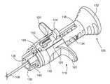
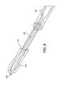
- FIG. 1shows a surgical device 100 used for delivering one or more fixation members to a surgical site.
- the device 100includes a handle 128 , a trigger 116 movable coupled to the handle 128 , a cover element 114 coupled to the trigger 116 , a tubular member 110 attached to the cover element 114 , and fixation member or anchor 102 having a flexible member or suture 104 ( FIG. 8 ) interwoven through the fixation member 102 .
- the fixation member 102 and suture 104are disposed in a distal end 106 of an elongated inserter 108 ( FIG. 8 ).
- the elongated inserter 108is slidably positioned within the tubular member 110 .
- the proximal end 112 of tubular member 110is coupled to the cover element 114 .
- the proximal end of the delivery device 100is shown in more detail in FIG. 2 .
- the cover element 114is coupled to a cover 126 and the trigger 116 .
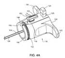
- the trigger 116includes a body 118 , finger engagable elements 120 emending generally perpendicular from a longitudinal axis of the body 118 , a circumferential groove 122 , and a button 124 .
- the trigger 116is movably coupled to the handle 128 .
- the button 124interacts with cutout portions 130 ( FIG. 3 ) in the handle 128 to lock the motion of the trigger 116 with respect to the handle 128 .
- the button 124can be depressed, which eliminates the interference between the button 124 and the cutouts 130 allowing motion of the trigger 116 with respect to the handle 128 .
- the handle 128includes an enlarged proximal end 132 that may enhance a user's grip on the handle 128 .
- the proximal end 132is connected to or formed integral with a hollow elongated body 134 .
- the body 134includes a longitudinal slot 136 extending from a distal end 138 at least partially toward the proximal end 132 .
- One of the enlarged proximal end 132 or the proximal wall 137 of the slot 136may act as a stop for the trigger 116 .
- Distal end 138also includes two straight portions 139 a and 139 b .
- Cut out portions 130are provided along the slot 136 and are sized to receive a portion of the button 124 .
- the distal end 138includes mating features 140 to couple with the cover element 114 .
- the proximal end 133 of the body 134includes a protrusion 141 which interacts with the trigger 116 to act as a detent for the trigger 116 in the deployed orientation. The interaction of protrusions 141 and the trigger 116 may also create an audible click or sound.
- Groove 142 and openings 144 a , 144 b in the distal end 138 of the handle 128allow for routing of the suture 104 as will be explained in more detail below.
- the trigger 116shown in FIG. 4A , includes two finger engagable elements 120 protruding from either side of the body 118 .
- the finger engagable elements 120are designed to be grasped by a surgeon's fingers while the device is being operated, as described in more detail below.
- Slots 146 and 148extend from the distal end 150 of the trigger 116 and may be in contact with the groove 122 .
- the slot 148 and the groove 122are designed for routing of the suture 104 as shown.
- the groove 122runs circumferentially around the trigger's body 118 and allows for longer sutures to be wrapped around it, increasing the length of suture that can be used with the delivery device 100 .
- Trigger 116also includes a retention member 152 with a slot 153 which is used to cleat sutures 104 to keep them in place.
- Button 124fits in a rectangular cutout 125 in the proximal end 154 of the trigger 116 . In its upright position, the button 124 engages cutout portions 130 of the handle 128 ( FIG. 3A ) and prevents the trigger 116 from moving with respect to the handle 128 . When the button 124 is depressed, the trigger 116 is free to slide up and down the body 134 of the handle 128 .
- FIGS. 4B-4Eshow the trigger 116 , handle, 128 , and elongated inserter 108 in an assembled configuration.
- the elongated inserter 108is attached to a tongue 156 of the trigger 116 by, for example, insert molding, friction fit, welding or some other suitable attachment means, such that the elongated inserter 108 moves with the trigger 116 .
- the proximal end of the elongated inserter 108has reliefs 172 ( FIG. 6 ) to prevent the inserter 108 from pushing through the tongue 156 in the trigger 116 .
- the tongue 156 of the trigger 116fits through the slot 136 and within the hollow portion of the body 134 of the handle 128 , while the body 118 of the trigger 116 is slidingly coupled to the body 134 of the handle 128 .
- the mating features 158 of the button 124may engage the cutout portions 130 of the handle 128 , when the button is in its upright position ( FIG. 4E ) to prevent the trigger 116 from moving with respect to the handle 128 .
- the trigger 116may be injection molded and made of ABS.
- the trigger 116 and the handle 128are made of dissimilar materials to reduce the friction between the two which allows the trigger to slide along the body 134 of the handle more easily.
- the suture 104travels down the elongated inserter 108 and is routed out of the handle 128 through hole 144 a , and then back through hole 144 b before passing out of slot 148 and wrapping around trigger 116 . Some slack is left in the suture 104 . The ends of the suture 104 can be secured in the slot 153 on the retention member 152 .
- the cover element 114is coupled to the tubular member 110 by; for example, insert molding, welding, friction fit, or other suitable means.
- the cover element 114also includes mating features 162 to engage mating features 140 of the handle 128 ( FIGS. 3A and 3B ), and mating feature 160 to engage the cover 126 ( FIG. 1 ).
- a hollow cavity 164extends from the proximal end 166 of the cover element 114 towards its distal end 167 .
- the hollow cavity 164has two straight portions 168 a , 168 b which engage straight portions 139 a , 139 b of the handle 128 and allow the handle 128 and cover element 114 to rotate together, but limit the handle 128 and cover element 114 from rotating relative to each other.
- the edges of the hollow cavity 164have a chamfer 169 to provide lead-in for ease of assembly.
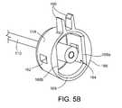
- FIG. 6is a cutaway view of the proximal end of the delivery device 100 .
- the trigger 116is shown pulled back towards the end of the proximal end 133 of the body 134 of the handle 128 . This is considered the “fully deployed” position, as described below.
- the protrusions 170 of the trigger 116are forced over the protrusions 141 of the handle 128 . This may produce an audible snap, allowing the surgeon to easily recognize when the delivery device 100 has reached its fully deployed state.
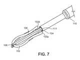
- FIGS. 7-9show the distal end of the delivery device 100 .
- Suture 104is threaded through a flexible fixation member 102 bent in a general u-shape and having two terminal ends 103 a , 103 b ( FIG. 10 ).
- the flexible fixation member 102is formed of a malleable or flexible body.
- the suture 104includes two terminal ends (not shown). One of the terminal ends is passed through the flexible fixation member 102 forming multiple curved portions of the suture 104 .
- the suture 104may slide with respect to the flexible fixation member 102 to form a cluster or bunch 30 including a number of folds as shown in FIG. 12C .
- the bunch 30may be used to secure tissue within a surgical site as will be described in more detail below.
- Portions of the suture 104 and flexible fixation member 102are seated in a forked distal end 106 of the elongated inserter 108 .
- the elongated inserter 108is rectangular in cross-section but could be any types of shapes, including circular, hexagonal, triangular, polygonal, or other suitable shape.
- the flat sides of the elongated inserter 108allow the suture to pass through the smaller distal end 111 of the tubular member 110 with the elongated inserter 108 without being pinched or compressed.
- the elongated inserter 108transitions from a rectangular profile at the distal end 106 to a circular profile at the proximal end and mates with the tongue 156 of the trigger 116 , as illustrated in FIG. 8 .
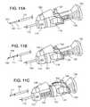
- FIGS. 11A-11C and 12A-12Cillustrate a method of using the delivery device 100 of FIG. 1 to deploy a flexible fixation member 102 to below a cortical layer 204 .
- FIG. 11Ashows a delivery device 100 which is ready for use.
- the delivery device 100is loaded with a flexible fixation member 102 and suture 104 assembly ( FIG. 10 ).
- the suture 104is routed through the tubular member 110 and through the delivery device 100 as described above, and then secured in retention member 151 .
- the cover 126hides the suture 104 that is secured in the retention member 152 to prevent premature uncleating, of the suture 104 , for example, by a user pulling the suture 104 loose from the retention member 152 . Referring to FIGS.
- a hole 202is drilled through the cortical layer 204 and into the cancellous layer 206 of bone using a drill guide 208 .
- the distal end of the delivery device 100is inserted into the drill guide ( FIG. 12A ).
- the forked distal end 106 of the elongated inserter 108moves the flexible fixation member 102 and suture 104 assembly past the cortical layer of bone 204 and into the cancellous layer 206 until the distal end 111 of the tubular member 110 is generally aligned with or past the bottom of the cortical layer 204 , as shown in FIG. 12B .
- the button 124is then depressed to allow the trigger 116 to be pulled towards the proximal end 132 of the handle 128 ( FIG. 11B ), pulling the elongated inserter 108 and the suture 104 back.
- the trigger 116is moved toward the proximal end 132 of the handle 128 , the retention member 152 and the suture 104 secured therein become accessible.
- the elongated inserter 108is drawn up into the tubular member 110 , slack in the suture 104 is taken up, and the suture 104 is tensioned.
- the flexible fixation member 102is larger than the distal tip 111 of the tubular member 110 .
- the flexible fixation member 102begins to bunch against the distal edge 111 of the tubular member 110 .
- the trigger 116is fully retracted, the flexible fixation member 102 is bunched such that it will not pull out of the hole 202 drilled in the bone.
- the suture 104can then be uncleated from the retention member 152 .
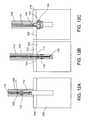
- FIG. 13Ais an alternative implementation of weaving the suture 304 through the flexible fixation member 302 .
- the flexible fixation member 302is not bent into a u-shape, but is substantially straight while both ends of the suture 304 are inserted in and out of the flexible fixation member 302 .
- This implementationalso includes an outer tubular member 306 which is inserted through the cortical layer 308 and into the cancellous layer 310 with the flexible fixation member 302 and suture 304 assembly. This outer tubular member 306 provides additional protection for the flexible fixation member 302 and suture 304 , and prevents any pinching or other damage to the flexible fixation member 302 or suture 304 during insertion.
- the method of deliveryis similar to the method described above.
- the suture 304is routed through the tubular member 312 and through the delivery device 100 as described above, and then secured in retention member 152 .
- the cover 126hides the suture 304 that is secured in the retention member 152 to prevent premature uncleating of the suture 304 .
- a hole 316is drilled through the cortical layer 308 and into the cancellous layer 310 of bone using a drill guide 318 .
- the distal end of the delivery device 100is inserted into the drill guide 318 ( FIG. 13B ).
- the distal end of the delivery device 100is advanced through the drill guide 318 until the outer tubular member 306 is past the cortical layer of bone 308 and into the cancellous layer 310 and the distal edge 314 of the tubular member 312 is generally aligned with or past the bottom of the cortical layer 308 , as shown in FIG. 13C .
- the button 124is then depressed to allow the trigger 116 to be pulled towards the proximal end 132 of the handle 128 , as shown in FIG. 11B , pulling the outer tubular member 306 and the suture 304 back.
- the retention member 152 and the suture 304 secured thereinbecome accessible.
- the flexible fixation member 302is larger than the distal tip 314 of the tubular member 312 . As the outer tubular member 306 and the suture 304 are drawn back, the flexible fixation member 302 begins to bunch against the distal edge 314 of the tubular member 312 . When the trigger 116 is fully retracted, the flexible fixation member 302 is bunched such that it will not pull out of the hole 316 drilled in the bone. The suture can then be nucleated from the retention member 152 .
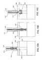
- FIGS. 14A-14Dshow another implementation of the flexible fixation member 402 and suture 404 .
- the flexible fixation member 402is straight while one end 405 a of the suture 404 is inserted in and out of the flexible fixation member 402 and one end 405 b of the suture 404 runs parallel to the straight fixation member 402 .
- the method of deliveryis the same method as described above with respect to FIGS. 13B-13E .
- the suture 404is routed through a tubular member 420 , through the delivery device 100 , and secured in retention member 152 .
- the cover 126hides the suture 404 that is secured in the retention member 152 .
- a hole 422is drilled through the cortical layer 424 and into the cancellous layer 426 of bone using a drill guide 428 .
- the distal end of the delivery device 100is inserted into the drill guide ( FIG. 14A ).
- the distal end of the delivery device 100is advanced through the drill guide 428 until the outer tubular member 430 is past the cortical layer of bone 424 and into the cancellous layer 426 and the distal edge 432 of the tubular member 420 is aligned with or past the bottom of the cortical layer 424 , as shown in FIG. 14B .
- the button 124is then depressed to allow the trigger 116 to be pulled towards the proximal end 132 of the handle 128 , as shown in FIG. 11B , pulling the outer tubular member 430 and the suture 404 back.
- the flexible fixation member 402is larger than the distal tip 432 of the tubular member 420 . When the trigger 116 is fully retracted, the flexible fixation member 402 is bunched such that it will not pull out of the hole 422 drilled in the bone.
- the suture 404can then be uncleated from the retention member 152 .
- FIGS. 15A-15Cshow another implementation of the delivery device.
- the tubular memberhas been omitted.
- the methodis similar to the method described above with respect to FIGS. 11A-12C .
- the delivery device 100is loaded with a flexible fixation member 502 and suture 504 assembly ( FIG. 10 ).
- the suture 504is routed through the delivery device 100 as described above, and then secured in retention member 152 .
- the cover 126hides the suture 504 that is secured in the retention member 152 .
- a hole 506is drilled in through the cortical layer 508 and into the cancellous layer 510 of bone using a drill guide 512 .
- the distal end of the delivery device 100is advanced through the drill guide 512 until the forked distal end 514 of the elongated inserter 516 pushes the flexible fixation member 502 and suture 504 assembly past the cortical layer of bone 508 and into the cancellous layer 510 , as shown in FIG. 158 .
- the button 124is then depressed to allow the trigger 116 to be pulled towards the proximal end 132 of the handle 128 ( FIG. 11B ), pulling the elongated inserter 516 and the suture 504 back.
- the flexible fixation member 502begins to bunch against the cortical layer 508 of bone.
- the flexible fixation member 502is bunched such that it will not pull out of the hole 506 drilled in the bone.
- the suture 504can then be uncleated from the retention member 152 .
- FIGS. 16A-16Fshow another implementation of the delivery device 600 .
- a guide 604includes a distal end portion 602 that is angled relative to a longitudinal axis L of the guide 604 , which allows the surgeon to achieve the ideal insertion angle of, for example, a flexible drill, such as the Flexible Twist Drill for 2.3 OsteoraptorTM Curved Guide, available from Smith & Nephew, Inc. of Andover Mass., and/or a flexible suture inserter at a quicker rate, thereby reducing the potential of damage to cartilage and other tissue within the joint area.
- a flexible drillsuch as the Flexible Twist Drill for 2.3 OsteoraptorTM Curved Guide
- the distal end portion 602 of the guide 604defines an opening 606 which is narrowed down via a cut or bushing 607 or swaged structure 607 a placed in the distal end portion 602 ( FIG. 16C, 16F ) relative to the remainder of the cannula 609 of the guide 604 .
- This narrowed portionaids in stabilizing and centering a flexible drill bit 900 , 901 or a flexible inserter 902 , 903 as it exits the guide 604 through the opening 606 , 605 , as shown in FIGS. 20A, 20B, and 20C .
- the distal end portion 602also includes one or more holes 608 .
- the holes 608are used during surgery to view the tissue anchor and, specifically the orientation of the tissue anchor, prior to inserting the anchor into tissue, such as hone.
- the holes 608may also be used to vent bone and other debris that may become located within the distal end portion 602 of the guide 604 during surgery.
- the distal end portion 602 of the guide 604also includes a serrated edge 610 , 611 for facilitating maintenance of the guide 604 on the bone during surgery, thereby substantially reducing slippage of the guide 604 off of the bone. Rather than a serrated edge 610 , 611 , the edge 610 , 611 may have other features known to one of skill that would help in maintaining the guide 604 on the bone and reduce slippage.
- the curved guide 604is further described in WO 2012/048050, which is incorporated herein by reference in its entirety.
- FIGS. 17A through 17Eillustrate exemplary implementations of a flexible elongated inserter 612 , 614 , 613 , 615 , 662 , respectively, that may be used in conjunction with the guide 604 for delivering anchors, such as the suture anchors described above, into tissue.
- the flexible elongated inserters 612 , 614 , 613 , 615 , 662each include an outer tubular member 616 , 618 , 617 , 619 , 664 , which includes at least a flexible portion 620 , 622 , 621 , 623 , 666 and a rigid, thinned portion 624 , 626 , 625 , 627 , 668 extending to a distal end 628 , 630 , 629 , 631 , 670 of the respective inserters 612 , 614 , 613 , 615 , 662 .
- the flexible portion 620 , 622 , 621 , 623 , 666permits the inserter 612 , 614 , 613 , 615 , 662 to substantially conform to the shape of the guide 604 when the inserter 612 , 614 , 613 , 615 , 662 is moved through the cannula 607 or 607 a of the guide 604 .
- the flexible portion 620 , 622 , 621 , 623 , 666may be made of a flexible material, such as, for example, nitinol or flexible plastics, or may be made from a coil cut tube ( FIG. 17A ), or a collection of engaging elements forming a puzzle cut tube ( FIG. 17B ), or a spring ( FIG.
- each of the inserters 612 , 614 , 613 , 615includes a pronged-end 632 , 634 , 633 , 635 , which receives a portion of a suture 650 ( FIG. 17B ), 651 ( FIG. 17C ), 652 ( FIG. 17E ) and a suture anchor 653 ( FIG. 17C ), 654 ( FIG. 17D ) as described above.
- the distal end 670 of inserter 662may also include a pronged-end (not shown) which receives a portion of a suture and a suture anchor as described above.
- the repair suture 650may be routed through a portion of the rigid portion 626 of the outer tubular member 618 for a certain distance, and then exit the outer tubular member 618 at a point along the rigid portion 626 or flexible portion 620 . Upon exit from the outer tubular member 618 , the suture 650 is then routed proximally along the outside of the outer tubular member 618 and between the guide 604 . This helps protect the suture from damage during use. In the alternative, as shown in FIG. 18B , the repair suture 650 may be routed proximally within the outer tubular member 618 . The same suture routing method is applicable to all the inserter options shown in FIG. 17 .
- the distal end portion 602 of the guide 604defines an opening 606 which narrows down via a cut or bushing 607 placed in the distal end portion 602 ( FIG. 16C ) relative to the remainder of the cannula 609 of the guide 604 .
- This narrowed portionaids in stabilizing and centering a flexible drill bit 900 or a flexible inserter 902 as it exits the guide 604 .
- FIGS. 19A-19Cillustrate additional implementations for assisting in the centering of the drill bit or inserter trajectory from the guide 604 . As shown in FIG. 19A , a flexible drill or inserter 702 is inserted within a curved guide 704 .
- the curved guide 704has a first inner diameter (ID 706 , which is concentric with a first outer diameter (OD) 708 as taken along line A-A of FIG. 19A .
- the guide 704has a second ID 710 , which is concentric with a second OD 712 as taken along line B-B of FIG. 19A .
- the longitudinal axis L′ of the drill or inserter 702may be angularly offset from the longitudinal axis L of the distal end 714 of the curved guide 704 because the drill or inserter 702 tends to remain straight.
- FIGS. 19B and 19Cshow implementations of angled guides 716 , 718 that aid in aligning the longitudinal axes L, L′ of the flexible drill or inserter 702 and the guide 716 , 718 .
- FIG. 19Bshows a guide 716 with a first ID 720 , which is concentric with a first OD 722 as taken along line A-A of FIG. 19B , and a second ID 724 , which is eccentric with respect to a second OD 726 taken along line B-B of FIG. 19B .
- the second ID 724is offset toward the inside of the guide 716 .
- FIG. 19Cshows a guide 718 with a first ID 728 , which is eccentric with respect to a first OD 730 as taken along line A-A of FIG. 19C , and a second ID 732 , which is concentric with a second OD 734 taken along line B-B of FIG. 19C .
- the first ID 728is offset toward the outside of the guide 718 .
- the offset first ID 728brings the longitudinal axis L′ of the distal end of the drill or inserter 702 into alignment with the longitudinal axis L of the distal end of the guide 718 .
- the offset IDs and ODsmay allow the device to support higher loads. For example, when bent, the concave side of the bent drill or inserter 702 supports the compressive or tensional loads. Thus, by thickening the wall of the concave side, more load may be supported.
- the fixation members and the flexible membersmay include a growth factor, such as, for example, an angiogenic factor.
- the fixation members and the flexible membersmay also be loaded with a bioactive material, a stimulant, or any substance that promotes healing of the tissue.
- the handlemay include more than one cut out portion to allow the trigger to be secured at different places along the body of the handle.
- the hollow cavity of the cover elementmay have more than two straight portions, one straight portion, or no straight portions. Elements 146 and 148 have been described as slots, but may be through holes or other shapes.
- the elongated inserterhas been described as having a rectangular profile at its distal end and a circular profile at its proximal end, other profile combinations, as well as constant profiles are contemplated.
- the elements of the delivery devicemay be made from other suitable materials.
- the handlemay be injection molded and made of polycarbonate. Accordingly, other implementations are within the scope of the following claims.
Landscapes
- Health & Medical Sciences (AREA)
- Surgery (AREA)
- Life Sciences & Earth Sciences (AREA)
- Medical Informatics (AREA)
- Animal Behavior & Ethology (AREA)
- Engineering & Computer Science (AREA)
- Biomedical Technology (AREA)
- Heart & Thoracic Surgery (AREA)
- Veterinary Medicine (AREA)
- Molecular Biology (AREA)
- Nuclear Medicine, Radiotherapy & Molecular Imaging (AREA)
- General Health & Medical Sciences (AREA)
- Public Health (AREA)
- Rheumatology (AREA)
- Dentistry (AREA)
- Oral & Maxillofacial Surgery (AREA)
- Orthopedic Medicine & Surgery (AREA)
- Surgical Instruments (AREA)
- Materials For Medical Uses (AREA)
Abstract
Description
Claims (16)
Priority Applications (1)
| Application Number | Priority Date | Filing Date | Title |
|---|---|---|---|
| US14/666,017US10010316B2 (en) | 2012-10-18 | 2015-03-23 | Flexible anchor delivery system |
Applications Claiming Priority (2)
| Application Number | Priority Date | Filing Date | Title |
|---|---|---|---|
| US13/654,855US8986327B2 (en) | 2012-10-18 | 2012-10-18 | Flexible anchor delivery system |
| US14/666,017US10010316B2 (en) | 2012-10-18 | 2015-03-23 | Flexible anchor delivery system |
Related Parent Applications (1)
| Application Number | Title | Priority Date | Filing Date |
|---|---|---|---|
| US13/654,855ContinuationUS8986327B2 (en) | 2012-10-18 | 2012-10-18 | Flexible anchor delivery system |
Publications (2)
| Publication Number | Publication Date |
|---|---|
| US20150190131A1 US20150190131A1 (en) | 2015-07-09 |
| US10010316B2true US10010316B2 (en) | 2018-07-03 |
Family
ID=49517674
Family Applications (10)
| Application Number | Title | Priority Date | Filing Date |
|---|---|---|---|
| US13/654,855Active2033-04-10US8986327B2 (en) | 2012-10-18 | 2012-10-18 | Flexible anchor delivery system |
| US14/433,684Active2033-12-18US10010314B2 (en) | 2012-10-18 | 2013-10-15 | Flexible anchor delivery system |
| US14/666,017Active2034-01-17US10010316B2 (en) | 2012-10-18 | 2015-03-23 | Flexible anchor delivery system |
| US16/000,980ActiveUS10292697B2 (en) | 2012-10-18 | 2018-06-06 | Flexible anchor delivery system |
| US16/373,090ActiveUS10617408B2 (en) | 2012-10-18 | 2019-04-02 | Flexible anchor delivery system |
| US16/684,713Active2034-06-01US11607211B2 (en) | 2012-10-18 | 2019-11-15 | Flexible anchor delivery system |
| US17/114,585Active2033-12-13US11723650B2 (en) | 2012-10-18 | 2020-12-08 | Flexible anchor delivery system |
| US17/560,737Active2034-05-01US12156648B2 (en) | 2012-10-18 | 2021-12-23 | Flexible anchor delivery system |
| US17/583,376PendingUS20220142636A1 (en) | 2012-10-18 | 2022-01-25 | Flexible anchor delivery system |
| US18/212,250ActiveUS12096929B2 (en) | 2012-10-18 | 2023-06-21 | Flexible anchor delivery system |
Family Applications Before (2)
| Application Number | Title | Priority Date | Filing Date |
|---|---|---|---|
| US13/654,855Active2033-04-10US8986327B2 (en) | 2012-10-18 | 2012-10-18 | Flexible anchor delivery system |
| US14/433,684Active2033-12-18US10010314B2 (en) | 2012-10-18 | 2013-10-15 | Flexible anchor delivery system |
Family Applications After (7)
| Application Number | Title | Priority Date | Filing Date |
|---|---|---|---|
| US16/000,980ActiveUS10292697B2 (en) | 2012-10-18 | 2018-06-06 | Flexible anchor delivery system |
| US16/373,090ActiveUS10617408B2 (en) | 2012-10-18 | 2019-04-02 | Flexible anchor delivery system |
| US16/684,713Active2034-06-01US11607211B2 (en) | 2012-10-18 | 2019-11-15 | Flexible anchor delivery system |
| US17/114,585Active2033-12-13US11723650B2 (en) | 2012-10-18 | 2020-12-08 | Flexible anchor delivery system |
| US17/560,737Active2034-05-01US12156648B2 (en) | 2012-10-18 | 2021-12-23 | Flexible anchor delivery system |
| US17/583,376PendingUS20220142636A1 (en) | 2012-10-18 | 2022-01-25 | Flexible anchor delivery system |
| US18/212,250ActiveUS12096929B2 (en) | 2012-10-18 | 2023-06-21 | Flexible anchor delivery system |
Country Status (12)
| Country | Link |
|---|---|
| US (10) | US8986327B2 (en) |
| EP (1) | EP2908739B1 (en) |
| JP (1) | JP6266634B2 (en) |
| KR (1) | KR20150075099A (en) |
| CN (2) | CN109288550B (en) |
| AU (1) | AU2013331427B2 (en) |
| BR (1) | BR112015008532A2 (en) |
| IN (1) | IN2015DN03003A (en) |
| MX (1) | MX2015004955A (en) |
| RU (1) | RU2015116365A (en) |
| WO (1) | WO2014062684A1 (en) |
| ZA (1) | ZA201502351B (en) |
Families Citing this family (34)
| Publication number | Priority date | Publication date | Assignee | Title |
|---|---|---|---|---|
| US10743854B2 (en) | 2010-01-20 | 2020-08-18 | Micro Interventional Devices, Inc. | Tissue closure device and method |
| US8795334B2 (en) | 2011-01-28 | 2014-08-05 | Smith & Nephew, Inc. | Tissue repair |
| US9421008B2 (en)* | 2011-09-23 | 2016-08-23 | Arthrex, Inc. | Soft suture-based anchors |
| US9084597B2 (en) | 2012-03-09 | 2015-07-21 | Smith & Nephew, Inc. | Suture-based knotless repair |
| US20140039552A1 (en) | 2012-08-03 | 2014-02-06 | Howmedica Osteonics Corp. | Soft tissue fixation devices and methods |
| US9463011B2 (en) | 2012-08-17 | 2016-10-11 | Arthrex, Inc. | Soft anchors with soft eyelets |
| US9901334B2 (en) | 2012-10-12 | 2018-02-27 | Cayenne Medical, Inc. | Systems and methods for repairing soft tissues using nanofiber material |
| US8986327B2 (en)* | 2012-10-18 | 2015-03-24 | Smith & Nephew, Inc. | Flexible anchor delivery system |
| US9173652B2 (en)* | 2013-03-11 | 2015-11-03 | Linvatec Corporation | All-suture anchor inserter |
| US9649223B2 (en)* | 2013-06-13 | 2017-05-16 | Innfocus, Inc. | Inserter for tubular medical implant devices |
| US9962150B2 (en)* | 2013-12-20 | 2018-05-08 | Arthrocare Corporation | Knotless all suture tissue repair |
| EP3096817B8 (en)* | 2014-01-22 | 2018-12-26 | Regenexx, LLC | Percutaneous delivery device for tendon-ligament-muscle repair |
| US9717491B2 (en)* | 2014-03-10 | 2017-08-01 | Biomet Sports Medicine, Llc | Method and apparatus for coupling soft tissue to bone |
| JP6717757B2 (en)* | 2014-06-10 | 2020-07-01 | マイクロ インターベンショナル デバイシズ,インコーポレイティド | Tissue closure device and method |
| EP3297558B1 (en) | 2015-05-22 | 2023-11-22 | Cayenne Medical, Inc. | Systems for repairing soft tissues |
| EP3383281B1 (en) | 2015-12-04 | 2024-01-24 | Crossroads Extremity Systems, LLC | Devices for anchoring tissue |
| WO2017139574A1 (en)* | 2016-02-12 | 2017-08-17 | Smith & Nephew, Inc. | Suture anchor with deformable cap |
| WO2017180473A1 (en) | 2016-04-11 | 2017-10-19 | Biomet Sports Medicine, Llc | Repair device and method for deploying anchors |
| KR101685894B1 (en)* | 2016-05-11 | 2016-12-14 | 아주약품(주) | Insert the anchor member for orthopedics |
| KR101682419B1 (en)* | 2016-10-06 | 2016-12-05 | 이준성 | Lifting Surgical Instrument having branch |
| US10631847B2 (en) | 2017-05-24 | 2020-04-28 | Karl Storz Se & Co. Kg | Bone anchor including only suture material and delivery device thereof |
| US11395647B2 (en)* | 2017-06-05 | 2022-07-26 | Conmed Corporation | Suture anchor construct and deployment device |
| US11723646B2 (en)* | 2017-07-24 | 2023-08-15 | Conmed Corporation | Self-drilling all-suture anchor |
| USD902405S1 (en) | 2018-02-22 | 2020-11-17 | Stryker Corporation | Self-punching bone anchor inserter |
| EP3856043A1 (en)* | 2018-09-24 | 2021-08-04 | CONMED Corporation | Backstop loader |
| CN113710298B (en)* | 2019-05-24 | 2024-02-06 | 贝克顿·迪金森公司 | Sheath stabilizer, sheath and stabilizer assembly and method thereof |
| WO2020237420A1 (en) | 2019-05-24 | 2020-12-03 | Becton, Dickinson And Company | Needle-tract assistant including components and methods thereof |
| US11793558B2 (en) | 2019-08-30 | 2023-10-24 | K2M, Inc. | All in one plate holder and spring loaded awl |
| CN213156540U (en)* | 2019-09-27 | 2021-05-11 | 巴德阿克塞斯系统股份有限公司 | Intraosseous systems and intraosseous access devices |
| CN112515722B (en)* | 2020-12-01 | 2024-05-24 | 花沐医疗科技(上海)有限公司 | Full suture anchor structure and implantation device thereof |
| CN112842451B (en)* | 2021-01-20 | 2025-05-23 | 上海市第六人民医院 | Device, kit and method for repairing and fixing articular cartilage |
| US20240148413A1 (en) | 2021-03-04 | 2024-05-09 | Smith & Nephew, Inc. | Methods and systems related to joint repair |
| FR3121592B1 (en)* | 2021-04-07 | 2023-07-14 | Rs4 | Suture anchor for anchoring soft tissue to bone |
| WO2023039494A1 (en)* | 2021-09-09 | 2023-03-16 | Responsive Arthroscopy, LLC | All-suture anchor |
Citations (106)
| Publication number | Priority date | Publication date | Assignee | Title |
|---|---|---|---|---|
| US3580256A (en) | 1969-06-30 | 1971-05-25 | Jack E Wilkinson | Pre-tied suture and method of suturing |
| US4605414A (en) | 1984-06-06 | 1986-08-12 | John Czajka | Reconstruction of a cruciate ligament |
| EP0328401A1 (en) | 1988-02-11 | 1989-08-16 | Unisearch Limited | Anastomosis augmentation device |
| US5217470A (en) | 1991-04-29 | 1993-06-08 | Weston Peter V | Apparatuses and methods for formation and use of a slipknot as a surgical suture knot |
| US5234445A (en) | 1992-09-18 | 1993-08-10 | Ethicon, Inc. | Endoscopic suturing device |
| US5306301A (en) | 1993-02-11 | 1994-04-26 | American Cyanamid Company | Graft attachment device and method of using same |
| US5405352A (en) | 1991-04-09 | 1995-04-11 | Weston; Peter V. | Suture knot, method for its formation and use, and knot forming apparatus |
| US5449367A (en) | 1993-08-02 | 1995-09-12 | Kadry; Othman | Pre-tied knot for surgical use and method of using same |
| US5451203A (en) | 1994-07-29 | 1995-09-19 | Orthopedic Systems, Inc. | Traction mechanism |
| JPH0852155A (en) | 1994-04-29 | 1996-02-27 | Ethicon Inc | Cuneate suture anchor,its planting method and its planting device |
| US5527341A (en) | 1991-05-24 | 1996-06-18 | Synthes (U.S.A) | Resorbable tendon and bone augmentation device |
| FR2743294A1 (en) | 1996-01-05 | 1997-07-11 | Ethnor | Mesh anchor for bone anchorage of a ligamentary transplant especially for repairing ligaments of the knee |
| US5690649A (en) | 1995-12-05 | 1997-11-25 | Li Medical Technologies, Inc. | Anchor and anchor installation tool and method |
| US5718717A (en) | 1996-08-19 | 1998-02-17 | Bonutti; Peter M. | Suture anchor |
| US5769894A (en) | 1997-02-05 | 1998-06-23 | Smith & Nephew, Inc. | Graft attachment device and method of attachment |
| US5893592A (en) | 1997-04-08 | 1999-04-13 | Ethicon Endo-Surgery, Inc. | Partially tied surgical knot |
| US5989252A (en) | 1997-02-28 | 1999-11-23 | Fumex; Laurent | Surgical device for anchoring in bone, and ancillary for inserting it |
| US6143029A (en) | 1996-03-11 | 2000-11-07 | Rippstein; Pascal Francois | Tendon guide device |
| US6193754B1 (en) | 1996-09-26 | 2001-02-27 | Neoligaments Limited | Attachment device for use in the implantation of prosthetic ligament |
| US20010002440A1 (en) | 1996-11-15 | 2001-05-31 | Bonutti Peter M. | Apparatus and method for use in positioning an anchor |
| US6296659B1 (en) | 2000-02-29 | 2001-10-02 | Opus Medical, Inc. | Single-tailed suturing method and apparatus |
| US20010041938A1 (en) | 1999-12-15 | 2001-11-15 | Dietmar Hein | Graft suspension device |
| GB2370227A (en) | 2000-11-21 | 2002-06-26 | Ahmed Mohamed Hosny Khashaba | Ligament tensioning device |
| US20020115999A1 (en) | 1999-07-23 | 2002-08-22 | Mcdevitt Dennis | System and method for attaching soft tissue to bone |
| US20030050666A1 (en) | 2001-09-13 | 2003-03-13 | Arthrex, Inc. | High strength suture material |
| US20030149448A1 (en) | 2002-02-04 | 2003-08-07 | Opus Medical, Inc. | Method and apparatus for attaching connective tissues to bone using a knotless suture anchoring device |
| WO2003092551A1 (en) | 2002-05-03 | 2003-11-13 | Ahmed Mohamed Hosny Khashaba | Ligament tensioning device |
| WO2004037094A2 (en) | 2002-10-23 | 2004-05-06 | Smith & Nephew, Inc. | Soft tissue attachment and repair |
| US20040133238A1 (en) | 1999-06-22 | 2004-07-08 | Cerier Jeffrey C. | Tissue fixation devices and methods of fixing tissue |
| US20040181234A1 (en) | 2000-11-16 | 2004-09-16 | Mcdevitt Dennis | Apparatus and method for attaching soft tissue to bone |
| US20050033364A1 (en) | 2001-12-06 | 2005-02-10 | Opus Medical, Inc. | Bone anchor insertion device |
| US20050149118A1 (en) | 2003-12-18 | 2005-07-07 | Ilya Koyfman | High strength suture with absorbable core and suture anchor combination |
| US20050187577A1 (en) | 2004-02-24 | 2005-08-25 | David Selvitelli | Methods and devices for repairing tissue |
| US20050209622A1 (en) | 2004-03-03 | 2005-09-22 | Scimed Life Systems, Inc. | Tissue removal probe with irrigation and aspiration ports |
| US20050251159A1 (en) | 2004-05-07 | 2005-11-10 | Usgi Medical Inc. | Methods and apparatus for grasping and cinching tissue anchors |
| US20050277985A1 (en) | 2004-06-14 | 2005-12-15 | Wert Zachary D | High-strength suture |
| US20060155328A1 (en) | 2003-03-18 | 2006-07-13 | Opus Medical, Inc. | Optimized suture braid |
| US20060178680A1 (en) | 2005-02-07 | 2006-08-10 | Regen Biologics, Inc. | System and method for all-inside suture fixation for implant attachment and soft tissue repair |
| US20060229671A1 (en) | 2005-04-08 | 2006-10-12 | Musculoskeletal Transplant Foundation | Suture anchor and suture anchor installation tool |
| US20060259076A1 (en) | 2005-03-30 | 2006-11-16 | Burkhart Stephen S | Looped high strength suture chain for knotless fixation |
| US20060293709A1 (en) | 2005-06-24 | 2006-12-28 | Bojarski Raymond A | Tissue repair device |
| US20070010857A1 (en) | 2005-07-05 | 2007-01-11 | Mitralign, Inc. | Tissue anchor, anchoring system and methods of using the same |
| US20070016244A1 (en) | 2005-07-06 | 2007-01-18 | Percutaneous Systems, Inc. | Methods and apparatus for deploying ureteral stents |
| WO2007037326A1 (en) | 2005-09-28 | 2007-04-05 | Olympus Medical Systems Corp. | Suturing device |
| US20070156174A1 (en) | 2006-01-03 | 2007-07-05 | Arthrotek, Inc. | Method and apparatus for repairing a meniscus |
| US20070185532A1 (en) | 2006-02-03 | 2007-08-09 | Arthrotek, Inc. | Soft tissue repair assembly and associated method |
| US20070239209A1 (en) | 2003-12-19 | 2007-10-11 | Radi Medical Systems Ab | Technique for securing a suture |
| WO2008022250A2 (en) | 2006-08-16 | 2008-02-21 | Wilson-Cook Medical, Inc. | Suturing device |
| US20080065114A1 (en) | 2006-02-03 | 2008-03-13 | Biomet Sports Medicine, Inc. | Method for Tissue Fixation |
| US20080140092A1 (en) | 2006-02-03 | 2008-06-12 | Stone Kevin T | Soft tissue repair device and associated methods |
| US20080140093A1 (en) | 2006-02-03 | 2008-06-12 | Stone Kevin T | Soft tissue repair device and associated methods |
| US7390329B2 (en) | 2004-05-07 | 2008-06-24 | Usgi Medical, Inc. | Methods for grasping and cinching tissue anchors |
| US20080208204A1 (en) | 2007-02-13 | 2008-08-28 | Arthrex, Inc. | Intraarticular graft length gauge |
| US20080208252A1 (en) | 2007-01-17 | 2008-08-28 | Arthrex, Inc. | Bunion repair using suture-button construct |
| US20080255613A1 (en) | 2007-04-10 | 2008-10-16 | Biomet Sports Medicine, Inc. | Adjustable knotless loops |
| US20080312689A1 (en) | 2004-11-05 | 2008-12-18 | Biomet Sports Medicine, Llc | Method and apparatus for coupling sof tissue to a bone |
| US20090036905A1 (en) | 2007-01-30 | 2009-02-05 | Reinhold Schmieding | Method of tissue fixation using cinch stitching |
| WO2009029914A1 (en) | 2007-08-31 | 2009-03-05 | Ken Christopher G M | Closure medical device |
| US20090069823A1 (en) | 2007-09-12 | 2009-03-12 | Foerster Seth A | Implant and delivery system for soft tissue repair |
| US20090082805A1 (en) | 2006-09-29 | 2009-03-26 | Biomet Sports Medicine, Llc | Adjustable knotless loops |
| US20090240335A1 (en) | 2008-03-24 | 2009-09-24 | Arcenio Gregory B | Expandable Devices for Emplacement in Body Parts and Methods Associated Therewith |
| US20090248068A1 (en) | 2008-03-25 | 2009-10-01 | Linvatec Corporation | Non-metallic knotless suture anchor |
| US7601165B2 (en) | 2006-09-29 | 2009-10-13 | Biomet Sports Medicine, Llc | Method and apparatus for forming a self-locking adjustable suture loop |
| US20090259260A1 (en) | 1999-10-20 | 2009-10-15 | Anulex Technologies, Inc. | Method and apparatus for the treatment of the intervertebral disc annulus |
| US20090306711A1 (en) | 2006-02-03 | 2009-12-10 | Biomet Sports Medicine, Llc | Method for Tissue Fixation |
| US20090312776A1 (en) | 2006-02-03 | 2009-12-17 | Biomet Sports Medicine, Llc | Method and Apparatus for Coupling Soft Tissue to a Bone |
| US20090318961A1 (en) | 2006-02-03 | 2009-12-24 | Biomet Sports Medicine,Llc | Method and Apparatus for Coupling Soft Tissue to a Bone |
| US20100023056A1 (en) | 2008-07-23 | 2010-01-28 | Guided Delivery Systems Inc. | Tether-anchor assemblies |
| US20100114163A1 (en) | 2008-11-03 | 2010-05-06 | Martin Daniel L | T-type suture anchor |
| US20100130989A1 (en) | 2008-11-26 | 2010-05-27 | Smith & Nephew, Inc. | Tissue Repair Device |
| US7736378B2 (en) | 2004-05-07 | 2010-06-15 | Usgi Medical, Inc. | Apparatus and methods for positioning and securing anchors |
| US20100211075A1 (en) | 2006-09-29 | 2010-08-19 | Biomet Sports Medicine, Llc | Fracture Fixation Device |
| US20100249809A1 (en) | 2009-03-11 | 2010-09-30 | Synthes Usa, Llc | Threadable knot soft tissue defect repair system |
| US20100256677A1 (en) | 2009-03-31 | 2010-10-07 | Arthrex, Inc. | Integrated adjustable button-suture-graft construct with two fixation devices |
| US20100268273A1 (en) | 2009-03-31 | 2010-10-21 | Ricardo Albertorio | Adjustable suture button construct and methods of tissue reconstruction |
| US20110009867A1 (en) | 2008-02-28 | 2011-01-13 | T.A.G. Medical Products Corporation Ltd. | Medical apparatus and method for attaching a suture to a bone |
| EP2277456A1 (en) | 2009-07-24 | 2011-01-26 | DePuy Mitek, Inc. | Surgical apparatus for repairing tissue |
| US20110022084A1 (en) | 2009-07-24 | 2011-01-27 | Mehmet Ziya Sengun | Methods and devices for repairing and anchoring damaged tissue |
| US20110022083A1 (en) | 2009-07-24 | 2011-01-27 | Dimatteo Kristian | Methods and devices for repairing and anchoring damaged tissue |
| US20110077667A1 (en) | 2008-06-06 | 2011-03-31 | Synthes Usa, Llc | Suture based tissue repair |
| US20110098727A1 (en) | 2006-09-29 | 2011-04-28 | Biomet Sports Medicine, Llc | Method and Apparatus for Securing Soft Tissue to Bone |
| US20110238111A1 (en) | 2010-03-28 | 2011-09-29 | Frank Joshua B | Soft Tissue Fixation Using A Looped Suture Construct |
| US20110264141A1 (en) | 2006-02-03 | 2011-10-27 | Biomet Sports Medicine, Llc | Flexible Anchors for Tissue Fixation |
| US20110270278A1 (en) | 2010-04-27 | 2011-11-03 | Tom Overes | Anchor assembly including expandable anchor |
| US20120046693A1 (en) | 2006-02-03 | 2012-02-23 | Biomet Sports Medicine, Llc | Method and Apparatus for Forming a Self-Locking Adjustable Loop |
| US8128658B2 (en) | 2004-11-05 | 2012-03-06 | Biomet Sports Medicine, Llc | Method and apparatus for coupling soft tissue to bone |
| US8128640B2 (en) | 2005-02-07 | 2012-03-06 | Ivy Sports Medicine LLC | System and method for all-inside suture fixation for implant attachment and soft tissue repair |
| US20120059417A1 (en) | 2006-02-03 | 2012-03-08 | Biomet Sports Medicine, Llc | Method and Apparatus for Coupling Soft Tissue to a Bone |
| US8137382B2 (en) | 2004-11-05 | 2012-03-20 | Biomet Sports Medicine, Llc | Method and apparatus for coupling anatomical features |
| WO2012048050A1 (en) | 2010-10-06 | 2012-04-12 | Smith & Nephew, Inc. | A system for use in tissue repair |
| US20120116450A1 (en) | 2010-11-04 | 2012-05-10 | Mcdevitt Dennis | Method and apparatus for securing an object to bone, including the provision and use of a novel suture assembly for securing suture to bone |
| US20120130422A1 (en) | 2010-11-24 | 2012-05-24 | Arthrocare Corporation | Novel suture |
| US20120150297A1 (en) | 2004-11-05 | 2012-06-14 | Biomet Sports Medicine, Llc | Method and Apparatus for Coupling Soft Tissue to a Bone |
| WO2012103536A1 (en) | 2011-01-28 | 2012-08-02 | Smith & Nephew, Inc. | Tissue repair |
| US8241305B2 (en) | 2008-05-08 | 2012-08-14 | Biomet Sports Medicine, Llc | Method for repairing a meniscal tear |
| WO2012112793A1 (en) | 2011-02-16 | 2012-08-23 | Linvatec Corporation | Method and apparatus for securing an object to bone |
| US20120239085A1 (en) | 2010-09-16 | 2012-09-20 | Ryan Schlotterback | Suture implant component and suture implant mechanism including such a component |
| US8303604B2 (en) | 2004-11-05 | 2012-11-06 | Biomet Sports Medicine, Llc | Soft tissue repair device and method |
| US20120290004A1 (en) | 2011-05-06 | 2012-11-15 | Linvatec Corporation | Soft anchor made from suture filament and suture tape |
| US20130018416A1 (en) | 2011-04-15 | 2013-01-17 | Linvatec Corporation | Soft suture anchor made of braided or monofilament suture |
| US20130035722A1 (en) | 2010-11-04 | 2013-02-07 | Mcdevitt Dennis | Method and apparatus for securing an object to bone, including the provision and use of a novel suture assembly for securing an object to bone |
| US20130110165A1 (en) | 2011-09-23 | 2013-05-02 | Arthrex, Inc. | Soft suture-based anchors |
| US20130123810A1 (en) | 2011-11-14 | 2013-05-16 | Eleven Blade Solutions, Inc. | Tissue repair assembly |
| WO2013134277A1 (en) | 2012-03-09 | 2013-09-12 | Smith & Nephew, Inc. | Suture-based knotless repair |
| US20130296934A1 (en) | 2012-05-07 | 2013-11-07 | Depuy Mitek, Inc. | Systems, devices, and methods for securing tissueusing snare assemblies and soft anchors |
| US20140114330A1 (en) | 2012-10-18 | 2014-04-24 | Smith & Nephew, Inc. | Flexible anchor delivery system |
Family Cites Families (50)
| Publication number | Priority date | Publication date | Assignee | Title |
|---|---|---|---|---|
| US2065659A (en)* | 1934-08-04 | 1936-12-29 | Arthur V Cullen | Fastening method and means |
| US4269246A (en) | 1979-05-10 | 1981-05-26 | Textron Inc. | Fastener and driver assembly |
| US4890615B1 (en)* | 1987-11-05 | 1993-11-16 | Linvatec Corporation | Arthroscopic suturing instrument |
| US5224946A (en)* | 1990-07-02 | 1993-07-06 | American Cyanamid Company | Bone anchor and method of anchoring a suture to a bone |
| US5100417A (en)* | 1990-07-13 | 1992-03-31 | American Cyanamid Company | Suture anchor and driver assembly |
| US5258016A (en)* | 1990-07-13 | 1993-11-02 | American Cyanamid Company | Suture anchor and driver assembly |
| US5484440A (en) | 1992-11-03 | 1996-01-16 | Zimmer, Inc. | Bone screw and screwdriver |
| US5431651A (en)* | 1993-02-08 | 1995-07-11 | Goble; E. Marlowe | Cross pin and set screw femoral and tibial fixation method |
| US5578057A (en)* | 1993-07-28 | 1996-11-26 | Mitek Surgical Products, Inc. | Anchoring device installation tool assembly and method |
| US6033405A (en) | 1994-09-15 | 2000-03-07 | Surgical Dynamics, Inc. | Apparatus and method for implant insertion |
| US5782862A (en)* | 1996-07-01 | 1998-07-21 | Bonutti; Peter M. | Suture anchor inserter assembly and method |
| CA2217406C (en) | 1996-10-04 | 2006-05-30 | United States Surgical Corporation | Suture anchor installation system with disposable loading unit |
| US5827291A (en)* | 1996-11-05 | 1998-10-27 | Linvatec Corporation | Suture anchor driver with suture retainer |
| US5957924A (en)* | 1997-05-22 | 1999-09-28 | Bionx Implants Oy | Installation tool for suture anchor |
| US5944724A (en)* | 1997-10-30 | 1999-08-31 | Mitek Surgical Products, Inc. | Suture anchor insertion system |
| US6068648A (en)* | 1998-01-26 | 2000-05-30 | Orthodyne, Inc. | Tissue anchoring system and method |
| US6436100B1 (en) | 1998-08-07 | 2002-08-20 | J. Lee Berger | Cannulated internally threaded bone screw and reduction driver device |
| US9521999B2 (en)* | 2005-09-13 | 2016-12-20 | Arthrex, Inc. | Fully-threaded bioabsorbable suture anchor |
| US6228096B1 (en)* | 1999-03-31 | 2001-05-08 | Sam R. Marchand | Instrument and method for manipulating an operating member coupled to suture material while maintaining tension on the suture material |
| US20040019353A1 (en) | 2002-02-01 | 2004-01-29 | Freid James M. | Spinal plate system for stabilizing a portion of a spine |
| US6951565B2 (en)* | 2002-04-24 | 2005-10-04 | Linvatec Biomaterials Ltd. | Device for inserting surgical implants |
| US20030204193A1 (en)* | 2002-04-25 | 2003-10-30 | Stefan Gabriel | Suture anchor insertion tool |
| US7329264B2 (en)* | 2002-10-07 | 2008-02-12 | Arthrex, Inc. | Instrument handle for storing suture and needles |
| US7354442B2 (en) | 2003-05-05 | 2008-04-08 | Warsaw Orthopedic, Inc. | Bone anchor and methods of using the same |
| US7780701B1 (en) | 2003-08-13 | 2010-08-24 | Biomet Sports Medicine, Llc | Suture anchor |
| US7645293B2 (en)* | 2004-04-21 | 2010-01-12 | United States Surgical Corporation | Suture anchor installation system and method |
| US20060089647A1 (en) | 2004-08-20 | 2006-04-27 | Culbert Brad S | Method and apparatus for delivering an agent |
| US20090187216A1 (en)* | 2006-05-18 | 2009-07-23 | Arthrex, Inc. | Fenestrated swivel anchor for knotless fixation of tissue |
| US20080009904A1 (en)* | 2006-03-17 | 2008-01-10 | Bourque Barnard J | Soft Tissue Fixation |
| US8758367B2 (en)* | 2006-09-05 | 2014-06-24 | Smith & Nephew, Inc. | Anchor delivery system |
| US8167906B2 (en) | 2006-11-01 | 2012-05-01 | Depuy Mitek, Inc. | Suture anchor with pulley |
| US8016832B2 (en) | 2007-05-02 | 2011-09-13 | Zimmer Spine, Inc. | Installation systems for spinal stabilization system and related methods |
| US8845685B2 (en)* | 2007-05-03 | 2014-09-30 | Biomet Sports Medicine, Llc | Anchor assembly and method of use |
| US8394103B2 (en) | 2007-10-16 | 2013-03-12 | Biomet Manufacturing Corp. | Method and apparatus for orthopedic fixation |
| US8236006B2 (en) | 2008-01-17 | 2012-08-07 | Life Spine, Inc. | One step entry pedicular preparation device and disc access system |
| US20090326545A1 (en) | 2008-06-26 | 2009-12-31 | Amedica Corporation | Systems and methods for inserting a bone anchor without a pilot hole |
| US8974494B2 (en)* | 2008-07-17 | 2015-03-10 | Smith & Nephew, Inc. | Surgical devices |
| US8052696B2 (en)* | 2008-08-22 | 2011-11-08 | The Anspach Effort, Inc. | Suture tensioning device |
| US9050077B2 (en)* | 2008-09-18 | 2015-06-09 | Smith & Nephew, Inc. | Suture anchor inserter |
| EP2498689A4 (en)* | 2009-11-09 | 2015-04-22 | Cardiovascular Technologies Inc | Tissue closure devices, device and systems for delivery, kits and methods therefor |
| JP2013510659A (en)* | 2009-11-10 | 2013-03-28 | スミス アンド ネフュー インコーポレーテッド | Tissue repair device |
| CN102138813B (en)* | 2010-01-29 | 2014-11-19 | 奥林巴斯医疗株式会社 | stapler |
| US9775702B2 (en) | 2010-03-10 | 2017-10-03 | Smith & Nephew, Inc. | Composite interference screws and drivers |
| US9451938B2 (en)* | 2010-04-27 | 2016-09-27 | DePuy Synthes Products, Inc. | Insertion instrument for anchor assembly |
| US8435264B2 (en)* | 2010-08-30 | 2013-05-07 | Depuy Mitek, Llc | Knotless suture anchor and driver |
| US9265494B2 (en) | 2011-12-20 | 2016-02-23 | Medos International Sarl | Knotless instability anchor |
| US9421010B2 (en) | 2012-06-20 | 2016-08-23 | Arthrex, Inc. | Whipping suture anchor |
| US9463011B2 (en) | 2012-08-17 | 2016-10-11 | Arthrex, Inc. | Soft anchors with soft eyelets |
| US9320512B2 (en) | 2012-08-17 | 2016-04-26 | Arthrex, Inc. | Self-cinching soft anchors |
| US9198650B2 (en) | 2012-12-27 | 2015-12-01 | Medos International Sarl | Multi-piece anchor inserter |
- 2012
- 2012-10-18USUS13/654,855patent/US8986327B2/enactiveActive
- 2013
- 2013-10-15RURU2015116365Apatent/RU2015116365A/ennot_activeApplication Discontinuation
- 2013-10-15JPJP2015537775Apatent/JP6266634B2/enactiveActive
- 2013-10-15WOPCT/US2013/065064patent/WO2014062684A1/enactiveApplication Filing
- 2013-10-15EPEP13786021.9Apatent/EP2908739B1/enactiveActive
- 2013-10-15AUAU2013331427Apatent/AU2013331427B2/enactiveActive
- 2013-10-15USUS14/433,684patent/US10010314B2/enactiveActive
- 2013-10-15BRBR112015008532Apatent/BR112015008532A2/ennot_activeIP Right Cessation
- 2013-10-15ININ3003DEN2015patent/IN2015DN03003A/enunknown
- 2013-10-15KRKR1020157012535Apatent/KR20150075099A/ennot_activeWithdrawn
- 2013-10-15CNCN201811107524.5Apatent/CN109288550B/enactiveActive
- 2013-10-15CNCN201380066543.7Apatent/CN104869920B/enactiveActive
- 2013-10-15MXMX2015004955Apatent/MX2015004955A/enunknown
- 2015
- 2015-03-23USUS14/666,017patent/US10010316B2/enactiveActive
- 2015-04-08ZAZA2015/02351Apatent/ZA201502351B/enunknown
- 2018
- 2018-06-06USUS16/000,980patent/US10292697B2/enactiveActive
- 2019
- 2019-04-02USUS16/373,090patent/US10617408B2/enactiveActive
- 2019-11-15USUS16/684,713patent/US11607211B2/enactiveActive
- 2020
- 2020-12-08USUS17/114,585patent/US11723650B2/enactiveActive
- 2021
- 2021-12-23USUS17/560,737patent/US12156648B2/enactiveActive
- 2022
- 2022-01-25USUS17/583,376patent/US20220142636A1/enactivePending
- 2023
- 2023-06-21USUS18/212,250patent/US12096929B2/enactiveActive
Patent Citations (153)
| Publication number | Priority date | Publication date | Assignee | Title |
|---|---|---|---|---|
| US3580256A (en) | 1969-06-30 | 1971-05-25 | Jack E Wilkinson | Pre-tied suture and method of suturing |
| US4605414A (en) | 1984-06-06 | 1986-08-12 | John Czajka | Reconstruction of a cruciate ligament |
| EP0328401A1 (en) | 1988-02-11 | 1989-08-16 | Unisearch Limited | Anastomosis augmentation device |
| US5405352A (en) | 1991-04-09 | 1995-04-11 | Weston; Peter V. | Suture knot, method for its formation and use, and knot forming apparatus |
| US5217470A (en) | 1991-04-29 | 1993-06-08 | Weston Peter V | Apparatuses and methods for formation and use of a slipknot as a surgical suture knot |
| US5527341A (en) | 1991-05-24 | 1996-06-18 | Synthes (U.S.A) | Resorbable tendon and bone augmentation device |
| US5234445A (en) | 1992-09-18 | 1993-08-10 | Ethicon, Inc. | Endoscopic suturing device |
| US5306301A (en) | 1993-02-11 | 1994-04-26 | American Cyanamid Company | Graft attachment device and method of using same |
| US5645588A (en) | 1993-02-11 | 1997-07-08 | Acufex Microsurgical, Inc. | Graft attachment device |
| US5449367A (en) | 1993-08-02 | 1995-09-12 | Kadry; Othman | Pre-tied knot for surgical use and method of using same |
| JPH0852155A (en) | 1994-04-29 | 1996-02-27 | Ethicon Inc | Cuneate suture anchor,its planting method and its planting device |
| US5451203A (en) | 1994-07-29 | 1995-09-19 | Orthopedic Systems, Inc. | Traction mechanism |
| US5690649A (en) | 1995-12-05 | 1997-11-25 | Li Medical Technologies, Inc. | Anchor and anchor installation tool and method |
| FR2743294A1 (en) | 1996-01-05 | 1997-07-11 | Ethnor | Mesh anchor for bone anchorage of a ligamentary transplant especially for repairing ligaments of the knee |
| US6143029A (en) | 1996-03-11 | 2000-11-07 | Rippstein; Pascal Francois | Tendon guide device |
| US5718717A (en) | 1996-08-19 | 1998-02-17 | Bonutti; Peter M. | Suture anchor |
| US6193754B1 (en) | 1996-09-26 | 2001-02-27 | Neoligaments Limited | Attachment device for use in the implantation of prosthetic ligament |
| US20010002440A1 (en) | 1996-11-15 | 2001-05-31 | Bonutti Peter M. | Apparatus and method for use in positioning an anchor |
| US5769894A (en) | 1997-02-05 | 1998-06-23 | Smith & Nephew, Inc. | Graft attachment device and method of attachment |
| US5989252A (en) | 1997-02-28 | 1999-11-23 | Fumex; Laurent | Surgical device for anchoring in bone, and ancillary for inserting it |
| US5893592A (en) | 1997-04-08 | 1999-04-13 | Ethicon Endo-Surgery, Inc. | Partially tied surgical knot |
| US20040133238A1 (en) | 1999-06-22 | 2004-07-08 | Cerier Jeffrey C. | Tissue fixation devices and methods of fixing tissue |
| US20040220573A1 (en) | 1999-07-23 | 2004-11-04 | Ethicon, Inc. | System and method for attaching soft tissue to bone |
| US20110152929A1 (en) | 1999-07-23 | 2011-06-23 | Depuy Mitek, Inc. | System and method for attaching soft tissue to bone |
| US20110152885A1 (en) | 1999-07-23 | 2011-06-23 | Depuy Mitek, Inc. | System And Method For Attaching Soft Tissue To Bone |
| US20020115999A1 (en) | 1999-07-23 | 2002-08-22 | Mcdevitt Dennis | System and method for attaching soft tissue to bone |
| US20090259260A1 (en) | 1999-10-20 | 2009-10-15 | Anulex Technologies, Inc. | Method and apparatus for the treatment of the intervertebral disc annulus |
| US6517578B2 (en) | 1999-12-15 | 2003-02-11 | Atlantech Medical Devices Limited | Graft suspension device |
| US20010041938A1 (en) | 1999-12-15 | 2001-11-15 | Dietmar Hein | Graft suspension device |
| US20020029066A1 (en) | 2000-02-29 | 2002-03-07 | Opus Medical, Inc. | Single-tailed suturing method and apparatus |
| US6296659B1 (en) | 2000-02-29 | 2001-10-02 | Opus Medical, Inc. | Single-tailed suturing method and apparatus |
| US20040181234A1 (en) | 2000-11-16 | 2004-09-16 | Mcdevitt Dennis | Apparatus and method for attaching soft tissue to bone |
| US20110098728A1 (en) | 2000-11-16 | 2011-04-28 | Depuy Mitek, Inc. | Apparatus and method for attaching soft tissue to bone |
| GB2370227A (en) | 2000-11-21 | 2002-06-26 | Ahmed Mohamed Hosny Khashaba | Ligament tensioning device |
| US20030050666A1 (en) | 2001-09-13 | 2003-03-13 | Arthrex, Inc. | High strength suture material |
| US20050033364A1 (en) | 2001-12-06 | 2005-02-10 | Opus Medical, Inc. | Bone anchor insertion device |
| US20030149448A1 (en) | 2002-02-04 | 2003-08-07 | Opus Medical, Inc. | Method and apparatus for attaching connective tissues to bone using a knotless suture anchoring device |
| WO2003092551A1 (en) | 2002-05-03 | 2003-11-13 | Ahmed Mohamed Hosny Khashaba | Ligament tensioning device |
| WO2004037094A2 (en) | 2002-10-23 | 2004-05-06 | Smith & Nephew, Inc. | Soft tissue attachment and repair |
| JP2006503655A (en) | 2002-10-23 | 2006-02-02 | スミス アンド ネフュー インコーポレーテッド | Soft tissue attachment and repair |
| US20060155328A1 (en) | 2003-03-18 | 2006-07-13 | Opus Medical, Inc. | Optimized suture braid |
| US20050149118A1 (en) | 2003-12-18 | 2005-07-07 | Ilya Koyfman | High strength suture with absorbable core and suture anchor combination |
| US20080255557A1 (en) | 2003-12-18 | 2008-10-16 | Ilya Koyfman | High strength suture with absorbable core and suture anchor combination |
| US20070239209A1 (en) | 2003-12-19 | 2007-10-11 | Radi Medical Systems Ab | Technique for securing a suture |
| US20050187577A1 (en) | 2004-02-24 | 2005-08-25 | David Selvitelli | Methods and devices for repairing tissue |
| US20080188893A1 (en) | 2004-02-24 | 2008-08-07 | Depuy Mitek, Inc. | Methods and devices for repairing tissue |
| US7390332B2 (en) | 2004-02-24 | 2008-06-24 | Depuy Mitek, Inc. | Methods and devices for repairing tissue |
| US20050209622A1 (en) | 2004-03-03 | 2005-09-22 | Scimed Life Systems, Inc. | Tissue removal probe with irrigation and aspiration ports |
| US8057511B2 (en) | 2004-05-07 | 2011-11-15 | Usgi Medical, Inc. | Apparatus and methods for positioning and securing anchors |
| US20050251159A1 (en) | 2004-05-07 | 2005-11-10 | Usgi Medical Inc. | Methods and apparatus for grasping and cinching tissue anchors |
| US8308765B2 (en) | 2004-05-07 | 2012-11-13 | Usgi Medical, Inc. | Apparatus and methods for positioning and securing anchors |
| US7390329B2 (en) | 2004-05-07 | 2008-06-24 | Usgi Medical, Inc. | Methods for grasping and cinching tissue anchors |
| US7736378B2 (en) | 2004-05-07 | 2010-06-15 | Usgi Medical, Inc. | Apparatus and methods for positioning and securing anchors |
| US20050277985A1 (en) | 2004-06-14 | 2005-12-15 | Wert Zachary D | High-strength suture |
| US20080312689A1 (en) | 2004-11-05 | 2008-12-18 | Biomet Sports Medicine, Llc | Method and apparatus for coupling sof tissue to a bone |
| US8118836B2 (en) | 2004-11-05 | 2012-02-21 | Biomet Sports Medicine, Llc | Method and apparatus for coupling soft tissue to a bone |
| US8303604B2 (en) | 2004-11-05 | 2012-11-06 | Biomet Sports Medicine, Llc | Soft tissue repair device and method |
| US20120150297A1 (en) | 2004-11-05 | 2012-06-14 | Biomet Sports Medicine, Llc | Method and Apparatus for Coupling Soft Tissue to a Bone |
| US8137382B2 (en) | 2004-11-05 | 2012-03-20 | Biomet Sports Medicine, Llc | Method and apparatus for coupling anatomical features |
| US8128658B2 (en) | 2004-11-05 | 2012-03-06 | Biomet Sports Medicine, Llc | Method and apparatus for coupling soft tissue to bone |
| US8128640B2 (en) | 2005-02-07 | 2012-03-06 | Ivy Sports Medicine LLC | System and method for all-inside suture fixation for implant attachment and soft tissue repair |
| WO2006086275A2 (en) | 2005-02-07 | 2006-08-17 | Regen Biologics, Inc. | System and method for all-inside suture fixation for implant attachment and soft tissue repair |
| US20060178680A1 (en) | 2005-02-07 | 2006-08-10 | Regen Biologics, Inc. | System and method for all-inside suture fixation for implant attachment and soft tissue repair |
| US20060259076A1 (en) | 2005-03-30 | 2006-11-16 | Burkhart Stephen S | Looped high strength suture chain for knotless fixation |
| US20060229671A1 (en) | 2005-04-08 | 2006-10-12 | Musculoskeletal Transplant Foundation | Suture anchor and suture anchor installation tool |
| US20060293709A1 (en) | 2005-06-24 | 2006-12-28 | Bojarski Raymond A | Tissue repair device |
| WO2007005394A1 (en) | 2005-07-05 | 2007-01-11 | Mitralign, Inc. | Tissue anchor and methods of using the same |
| US20070010857A1 (en) | 2005-07-05 | 2007-01-11 | Mitralign, Inc. | Tissue anchor, anchoring system and methods of using the same |
| US7972292B2 (en) | 2005-07-06 | 2011-07-05 | Percutaneous Systems, Inc. | Methods and apparatus for deploying ureteral stents |
| US20070016244A1 (en) | 2005-07-06 | 2007-01-18 | Percutaneous Systems, Inc. | Methods and apparatus for deploying ureteral stents |
| WO2007037326A1 (en) | 2005-09-28 | 2007-04-05 | Olympus Medical Systems Corp. | Suturing device |
| US20070156174A1 (en) | 2006-01-03 | 2007-07-05 | Arthrotek, Inc. | Method and apparatus for repairing a meniscus |
| US20090306711A1 (en) | 2006-02-03 | 2009-12-10 | Biomet Sports Medicine, Llc | Method for Tissue Fixation |
| US8298262B2 (en) | 2006-02-03 | 2012-10-30 | Biomet Sports Medicine, Llc | Method for tissue fixation |
| US20110264141A1 (en) | 2006-02-03 | 2011-10-27 | Biomet Sports Medicine, Llc | Flexible Anchors for Tissue Fixation |
| US20130158601A1 (en) | 2006-02-03 | 2013-06-20 | Biomet Sports Medicine, Llc | Soft Tissue Repair Assembly And Associated Method |
| US8088130B2 (en) | 2006-02-03 | 2012-01-03 | Biomet Sports Medicine, Llc | Method and apparatus for coupling soft tissue to a bone |
| US20090312776A1 (en) | 2006-02-03 | 2009-12-17 | Biomet Sports Medicine, Llc | Method and Apparatus for Coupling Soft Tissue to a Bone |
| US20090318961A1 (en) | 2006-02-03 | 2009-12-24 | Biomet Sports Medicine,Llc | Method and Apparatus for Coupling Soft Tissue to a Bone |
| US7909851B2 (en) | 2006-02-03 | 2011-03-22 | Biomet Sports Medicine, Llc | Soft tissue repair device and associated methods |
| US20130138123A1 (en) | 2006-02-03 | 2013-05-30 | Biomet Sports Medicine, Llc | Method And Apparatus For Coupling Soft Tissue To A Bone |
| US7905904B2 (en) | 2006-02-03 | 2011-03-15 | Biomet Sports Medicine, Llc | Soft tissue repair device and associated methods |
| US20130123813A1 (en) | 2006-02-03 | 2013-05-16 | Biomet Sports Medicine, Llc | Soft Tissue Repair Device and Associated Methods |
| US8409253B2 (en) | 2006-02-03 | 2013-04-02 | Biomet Sports Medicine, Llc | Soft tissue repair assembly and associated method |
| US7905903B2 (en) | 2006-02-03 | 2011-03-15 | Biomet Sports Medicine, Llc | Method for tissue fixation |
| US8361113B2 (en) | 2006-02-03 | 2013-01-29 | Biomet Sports Medicine, Llc | Method and apparatus for coupling soft tissue to a bone |
| US7749250B2 (en) | 2006-02-03 | 2010-07-06 | Biomet Sports Medicine, Llc | Soft tissue repair assembly and associated method |
| US20130023930A1 (en) | 2006-02-03 | 2013-01-24 | Biomet Sports Medicine, Llc | Method for Tissue Fixation |
| US20120046693A1 (en) | 2006-02-03 | 2012-02-23 | Biomet Sports Medicine, Llc | Method and Apparatus for Forming a Self-Locking Adjustable Loop |
| US20070185532A1 (en) | 2006-02-03 | 2007-08-09 | Arthrotek, Inc. | Soft tissue repair assembly and associated method |
| US20120053630A1 (en) | 2006-02-03 | 2012-03-01 | Biomet Sports Medicine, Llc | Method and Apparatus for Forming a Self-Locking Adjustable Loop |
| US20080140093A1 (en) | 2006-02-03 | 2008-06-12 | Stone Kevin T | Soft tissue repair device and associated methods |
| US20100268275A1 (en) | 2006-02-03 | 2010-10-21 | Biomet Sports Medicine, Llc | Soft Tissue Repair Assembly and Associated Method |
| US20080065114A1 (en) | 2006-02-03 | 2008-03-13 | Biomet Sports Medicine, Inc. | Method for Tissue Fixation |
| US20080140092A1 (en) | 2006-02-03 | 2008-06-12 | Stone Kevin T | Soft tissue repair device and associated methods |
| US20120059417A1 (en) | 2006-02-03 | 2012-03-08 | Biomet Sports Medicine, Llc | Method and Apparatus for Coupling Soft Tissue to a Bone |
| WO2008022250A2 (en) | 2006-08-16 | 2008-02-21 | Wilson-Cook Medical, Inc. | Suturing device |
| JP2010500912A (en) | 2006-08-16 | 2010-01-14 | ウィルソン−クック・メディカル・インコーポレーテッド | Suture device |
| US7658751B2 (en) | 2006-09-29 | 2010-02-09 | Biomet Sports Medicine, Llc | Method for implanting soft tissue |
| US20100211075A1 (en) | 2006-09-29 | 2010-08-19 | Biomet Sports Medicine, Llc | Fracture Fixation Device |
| US20100145384A1 (en) | 2006-09-29 | 2010-06-10 | Biomet Sport Medicine, Llc | Method for Implanting Soft Tissue |
| US20090082805A1 (en) | 2006-09-29 | 2009-03-26 | Biomet Sports Medicine, Llc | Adjustable knotless loops |
| US20110098727A1 (en) | 2006-09-29 | 2011-04-28 | Biomet Sports Medicine, Llc | Method and Apparatus for Securing Soft Tissue to Bone |
| US7959650B2 (en) | 2006-09-29 | 2011-06-14 | Biomet Sports Medicine, Llc | Adjustable knotless loops |
| US7601165B2 (en) | 2006-09-29 | 2009-10-13 | Biomet Sports Medicine, Llc | Method and apparatus for forming a self-locking adjustable suture loop |
| US20080208252A1 (en) | 2007-01-17 | 2008-08-28 | Arthrex, Inc. | Bunion repair using suture-button construct |
| US20090036905A1 (en) | 2007-01-30 | 2009-02-05 | Reinhold Schmieding | Method of tissue fixation using cinch stitching |
| US20080208204A1 (en) | 2007-02-13 | 2008-08-28 | Arthrex, Inc. | Intraarticular graft length gauge |
| US20080255613A1 (en) | 2007-04-10 | 2008-10-16 | Biomet Sports Medicine, Inc. | Adjustable knotless loops |
| CN101888810A (en) | 2007-08-31 | 2010-11-17 | 克里斯多佛·G·M·肯恩 | closed medical device |
| US20090062847A1 (en) | 2007-08-31 | 2009-03-05 | Ken Christopher G M | Closure medical device |
| US20090062846A1 (en) | 2007-08-31 | 2009-03-05 | Ken Christopher G M | Closure medical device |
| US7771455B2 (en) | 2007-08-31 | 2010-08-10 | Ken Christopher G M | Closure medical device |
| WO2009029914A1 (en) | 2007-08-31 | 2009-03-05 | Ken Christopher G M | Closure medical device |
| US8172871B2 (en) | 2007-08-31 | 2012-05-08 | Ken Christopher G M | Closure medical device |
| JP2010537746A (en) | 2007-08-31 | 2010-12-09 | ケン,クリストファー,ジー.エム. | Medical device for wound treatment |
| US20090069823A1 (en) | 2007-09-12 | 2009-03-12 | Foerster Seth A | Implant and delivery system for soft tissue repair |
| US20110009867A1 (en) | 2008-02-28 | 2011-01-13 | T.A.G. Medical Products Corporation Ltd. | Medical apparatus and method for attaching a suture to a bone |
| US20090240335A1 (en) | 2008-03-24 | 2009-09-24 | Arcenio Gregory B | Expandable Devices for Emplacement in Body Parts and Methods Associated Therewith |
| US20090248068A1 (en) | 2008-03-25 | 2009-10-01 | Linvatec Corporation | Non-metallic knotless suture anchor |
| US8241305B2 (en) | 2008-05-08 | 2012-08-14 | Biomet Sports Medicine, Llc | Method for repairing a meniscal tear |
| US20110077667A1 (en) | 2008-06-06 | 2011-03-31 | Synthes Usa, Llc | Suture based tissue repair |
| US20100023056A1 (en) | 2008-07-23 | 2010-01-28 | Guided Delivery Systems Inc. | Tether-anchor assemblies |
| US20100114163A1 (en) | 2008-11-03 | 2010-05-06 | Martin Daniel L | T-type suture anchor |
| US20100130989A1 (en) | 2008-11-26 | 2010-05-27 | Smith & Nephew, Inc. | Tissue Repair Device |
| US20100249809A1 (en) | 2009-03-11 | 2010-09-30 | Synthes Usa, Llc | Threadable knot soft tissue defect repair system |
| US20100268273A1 (en) | 2009-03-31 | 2010-10-21 | Ricardo Albertorio | Adjustable suture button construct and methods of tissue reconstruction |
| US20100256677A1 (en) | 2009-03-31 | 2010-10-07 | Arthrex, Inc. | Integrated adjustable button-suture-graft construct with two fixation devices |
| US20110022083A1 (en) | 2009-07-24 | 2011-01-27 | Dimatteo Kristian | Methods and devices for repairing and anchoring damaged tissue |
| EP2277456A1 (en) | 2009-07-24 | 2011-01-26 | DePuy Mitek, Inc. | Surgical apparatus for repairing tissue |
| JP2011025036A (en) | 2009-07-24 | 2011-02-10 | Depuy Mitek Inc | Apparatus and method for repairing tissue |
| US20110022084A1 (en) | 2009-07-24 | 2011-01-27 | Mehmet Ziya Sengun | Methods and devices for repairing and anchoring damaged tissue |
| US20110022061A1 (en) | 2009-07-24 | 2011-01-27 | Depuy Mitek, Inc. | Apparatus and method for repairing tissue |
| US20110238111A1 (en) | 2010-03-28 | 2011-09-29 | Frank Joshua B | Soft Tissue Fixation Using A Looped Suture Construct |
| US20110270278A1 (en) | 2010-04-27 | 2011-11-03 | Tom Overes | Anchor assembly including expandable anchor |
| US20120239085A1 (en) | 2010-09-16 | 2012-09-20 | Ryan Schlotterback | Suture implant component and suture implant mechanism including such a component |
| WO2012048050A1 (en) | 2010-10-06 | 2012-04-12 | Smith & Nephew, Inc. | A system for use in tissue repair |
| US20120116450A1 (en) | 2010-11-04 | 2012-05-10 | Mcdevitt Dennis | Method and apparatus for securing an object to bone, including the provision and use of a novel suture assembly for securing suture to bone |
| US20130035722A1 (en) | 2010-11-04 | 2013-02-07 | Mcdevitt Dennis | Method and apparatus for securing an object to bone, including the provision and use of a novel suture assembly for securing an object to bone |
| US20120215257A1 (en) | 2010-11-04 | 2012-08-23 | Mcdevitt Dennis | Method and apparatus for securing an object to bone, including the provision and use of a novel suture assembly for securing an object to bone |
| US20120130422A1 (en) | 2010-11-24 | 2012-05-24 | Arthrocare Corporation | Novel suture |
| WO2012103536A1 (en) | 2011-01-28 | 2012-08-02 | Smith & Nephew, Inc. | Tissue repair |
| US20120197271A1 (en) | 2011-01-28 | 2012-08-02 | Smith & Nephew, Inc. | Tissue repair |
| WO2012112793A1 (en) | 2011-02-16 | 2012-08-23 | Linvatec Corporation | Method and apparatus for securing an object to bone |
| US20130018416A1 (en) | 2011-04-15 | 2013-01-17 | Linvatec Corporation | Soft suture anchor made of braided or monofilament suture |
| US20120290004A1 (en) | 2011-05-06 | 2012-11-15 | Linvatec Corporation | Soft anchor made from suture filament and suture tape |
| US20130110165A1 (en) | 2011-09-23 | 2013-05-02 | Arthrex, Inc. | Soft suture-based anchors |
| US20130123810A1 (en) | 2011-11-14 | 2013-05-16 | Eleven Blade Solutions, Inc. | Tissue repair assembly |
| WO2013134277A1 (en) | 2012-03-09 | 2013-09-12 | Smith & Nephew, Inc. | Suture-based knotless repair |
| US20130237997A1 (en) | 2012-03-09 | 2013-09-12 | Smith & Nephew, Inc. | Suture-based knotless repair |
| US20130296934A1 (en) | 2012-05-07 | 2013-11-07 | Depuy Mitek, Inc. | Systems, devices, and methods for securing tissueusing snare assemblies and soft anchors |
| US20140114330A1 (en) | 2012-10-18 | 2014-04-24 | Smith & Nephew, Inc. | Flexible anchor delivery system |
| WO2014062684A1 (en) | 2012-10-18 | 2014-04-24 | Smith & Nephew, Inc. | Flexible anchor delivery system |
Non-Patent Citations (42)
| Title |
|---|
| "Endobutton CL," Smith and Nephew, Inc., reprinted from http://endo.smith-nephew.com/es/Standard.asp?NodeID=2715, on Nov. 22, 2010, 1 page. |
| "Endobutton Direct: Fixation Device," Smith & Nephew, Inc., reprinted from http://global.smith-nephew.com/us/product23376_5895.htm, on Nov. 22, 2010, 3 pages. |
| "Technique for ACL reconstruction with Acufex Director Drill Guide and Endobutton CL" copyright 1999, Smith & Nephew, Inc., 20 pages. |
| Decision of Rejection from related Japanese Application No. 2013-551405 dated Jul. 25, 2016. |
| First Office Action from related Chinese Application No. 201380013146.3 dated Apr. 14, 2016. |
| From, Stuart, "ACL Reconstruction with Bone-Tendon-Bone Transplants using the Endobutton CL BTB Fixation System," Smith & Nephew, Inc., copyright 2004, printed on Apr. 4, 11 pages. |
| Game Plan: Innovative Products to be Launched AAOS 2010, Biomet Sports Medicine, Spring 2010, vol. 2, No. 3, 1 page. |
| Glousman, R., et al., "JuggerKnot Soft Anchor Surgical Technique," Biomet Sports Medicine, 2010, 1 page. |
| International Search Report Application No. PCT/US2013/029143, dated Jun. 13, 2013. |
| International Search Report Application No. PCT/US2013/065064, dated Feb. 21, 2014. |
| International Search Report for International Application No. PCT/US2012/023056, dated Jun. 13, 2012. |
| International Search Report from corresponding International Application No. 201380066543.7, dated Dec. 29, 2017. |
| Lawhorn, K., "MaxFire MarXmen Device Surgical Technique," Biomet Sports Medicine, 2010, 1 page. |
| Office Action from related Chinese Application No. 201380066543.7 dated Sep. 27, 2016. |
| Office Action from related European Application No. 13712402.0-1654 dated Nov. 4, 2016. |
| Office Action from related Japanese Application No. 2014-561043 dated Jan. 16, 2017. |
| Office Action from related Russian Application No. 2014136769/14(059452) dated Dec. 30, 2017. |
| Office Communication from related European Application No. 13786021.9-1654 dated Dec. 13, 2016. |
| Patent Examination Report from related Australian Application No. 2013230095 dated Nov. 2, 2016. |
| Scope This Out, vol. 10, No. 2, Summer 2008, 8 pages. |
| Scope this Out, vol. 12, No. 1, Spring 2010, 8 pages. |
| Scope This Out, vol. 12, No. 2, Fall 2010, 8 pages. |
| Shoulder Restoration System: Arthroscopic Bankart Repair Using the Y-KnotTM 1.3mm All-Suture Anchor, ConMedTM Linvatec, 2011, 4 pages. |
| Shoulder Restoration System: Y-KnotTM 1.3mm All-Suture Anchor, ConMedTM Linvatec, 2011, 4 pages. |
| ToggleLOC: Femoral Fixation Device with Zip Loop Technology, Biomet Sports Medicine, Inc., 2007, 8 pages. |
| Translation of Search Report from related Chinese Application No. 201380013146.3 dated May 26, 2016. |
| U.S. Appl. No. 61/328,251, filed Apr. 27, 2010, Overes. |
| U.S. Appl. No. 61/398,699, filed Jun. 29, 2010, Overes et al. |
| U.S. Appl. No. 61/410,027, filed Nov. 4, 2010, McDevitt et al. |
| U.S. Appl. No. 61/419,334, filed Dec. 3, 2010, McDevitt et al. |
| U.S. Appl. No. 61/422,859, filed Dec. 14, 2010, McDevitt et al. |
| U.S. Appl. No. 61/432,755, filed Jan. 14, 2011, Henrichsen et al. |
| U.S. Appl. No. 61/443,142, filed Feb. 15, 2011, Overes. |
| U.S. Appl. No. 61/443,325, filed Feb. 16, 2011, McDevitt et al. |
| U.S. Appl. No. 61/461,490, filed Jan. 18, 2011, Henrichsen et al. |
| U.S. Appl. No. 61/517,203, filed Apr. 15, 2011, Lombardo et al. |
| U.S. Appl. No. 61/517,221, filed Apr. 15, 2011, Lombardo et al. |
| U.S. Appl. No. 61/517,230, filed Apr. 15, 2011, Lombardo. |
| U.S. Appl. No. 61/518,519, filed May 6, 2011, Lombardo et al. |
| U.S. Appl. No. 61/538,163, filed Sep. 23, 2011, Burkhart et al. |
| U.S. Appl. No. 61/559,672, filed Nov. 14, 2011, Brown et al. |
| Written Opinion of the International Searching Authority and the and International Preliminary Report on Patentability for International Application No. PCT/US2012/023056, dated Jun. 13, 2012. |
Also Published As
Similar Documents
| Publication | Publication Date | Title |
|---|---|---|
| US20220110623A1 (en) | Flexible anchor delivery system | |
| EP2014241B1 (en) | Applicator for suture/button construct | |
| JP6121155B2 (en) | Nodule instability anchor | |
| AU2013230095B2 (en) | Suture-based knotless repair | |
| JP6338858B2 (en) | Tissue repair | |
| CN110711003B (en) | Biceps tenodesis implant and delivery tool | |
| CN106137287B (en) | Knotless suture anchor guide | |
| US9615822B2 (en) | Insertion tools and method for soft anchor | |
| EP2574307B1 (en) | Graft introducer | |
| WO2025141577A1 (en) | System and method for forming a bore in a bone and inserting at least one anchor |
Legal Events
| Date | Code | Title | Description |
|---|---|---|---|
| AS | Assignment | Owner name:SMITH & NEPHEW, INC., TENNESSEE Free format text:ASSIGNMENT OF ASSIGNORS INTEREST;ASSIGNOR:ARAI, TATSUYA;REEL/FRAME:035676/0675 Effective date:20121002 Owner name:SMITH & NEPHEW, INC., TENNESSEE Free format text:ASSIGNMENT OF ASSIGNORS INTEREST;ASSIGNOR:MCKENZIE, BRETT A.;REEL/FRAME:035676/0657 Effective date:20120727 Owner name:SMITH & NEPHEW, INC., TENNESSEE Free format text:ASSIGNMENT OF ASSIGNORS INTEREST;ASSIGNOR:LUNN, RICHARD M.;REEL/FRAME:035676/0672 Effective date:20120801 Owner name:SMITH & NEPHEW, INC., TENNESSEE Free format text:ASSIGNMENT OF ASSIGNORS INTEREST;ASSIGNOR:HOUSMAN, MARK EDWIN;REEL/FRAME:035676/0678 Effective date:20121002 Owner name:SMITH & NEPHEW, INC., TENNESSEE Free format text:ASSIGNMENT OF ASSIGNORS INTEREST;ASSIGNOR:ASTORINO, STEVEN W.;REEL/FRAME:035676/0665 Effective date:20120726 Owner name:SMITH & NEPHEW, INC., TENNESSEE Free format text:ASSIGNMENT OF ASSIGNORS INTEREST;ASSIGNOR:KARASIC, GEOFFREY I.;REEL/FRAME:035676/0654 Effective date:20120725 Owner name:SMITH & NEPHEW, INC., TENNESSEE Free format text:ASSIGNMENT OF ASSIGNORS INTEREST;ASSIGNOR:GATTURNA, ROLAND FRANCIS;REEL/FRAME:035676/0684 Effective date:20121002 | |
| AS | Assignment | Owner name:SMITH & NEPHEW, TENNESSEE Free format text:ASSIGNMENT OF ASSIGNORS INTEREST;ASSIGNOR:KOSKI, MATTHEW E;REEL/FRAME:035951/0107 Effective date:20120807 | |
| STCF | Information on status: patent grant | Free format text:PATENTED CASE | |
| MAFP | Maintenance fee payment | Free format text:PAYMENT OF MAINTENANCE FEE, 4TH YEAR, LARGE ENTITY (ORIGINAL EVENT CODE: M1551); ENTITY STATUS OF PATENT OWNER: LARGE ENTITY Year of fee payment:4 |