US10008317B2 - Voltage or impedance-injection method using transformers with multiple secondary windings for dynamic power flow control - Google Patents
Voltage or impedance-injection method using transformers with multiple secondary windings for dynamic power flow controlDownload PDFInfo
- Publication number
- US10008317B2 US10008317B2US15/069,785US201615069785AUS10008317B2US 10008317 B2US10008317 B2US 10008317B2US 201615069785 AUS201615069785 AUS 201615069785AUS 10008317 B2US10008317 B2US 10008317B2
- Authority
- US
- United States
- Prior art keywords
- transmission line
- module
- transformer
- converter
- converters
- Prior art date
- Legal status (The legal status is an assumption and is not a legal conclusion. Google has not performed a legal analysis and makes no representation as to the accuracy of the status listed.)
- Active, expires
Links
- 238000002347injectionMethods0.000titleclaimsabstractdescription86
- 239000007924injectionSubstances0.000titleclaimsabstractdescription86
- 238000004804windingMethods0.000titleclaimsabstractdescription84
- 238000000034methodMethods0.000titleclaimsdescription16
- 230000005540biological transmissionEffects0.000claimsabstractdescription98
- 230000006872improvementEffects0.000claimsdescription9
- 230000008878couplingEffects0.000claimsdescription7
- 238000010168coupling processMethods0.000claimsdescription7
- 238000005859coupling reactionMethods0.000claimsdescription7
- 238000009434installationMethods0.000claimsdescription2
- 239000012212insulatorSubstances0.000claimsdescription2
- 230000001939inductive effectEffects0.000abstractdescription29
- 230000001186cumulative effectEffects0.000abstractdescription4
- 239000000284extractSubstances0.000abstractdescription2
- 238000010586diagramMethods0.000description7
- 238000012546transferMethods0.000description6
- 230000008901benefitEffects0.000description3
- 238000013461designMethods0.000description3
- 238000004891communicationMethods0.000description2
- 238000001816coolingMethods0.000description2
- 238000012937correctionMethods0.000description2
- 238000007667floatingMethods0.000description2
- 230000008439repair processEffects0.000description2
- 239000004065semiconductorSubstances0.000description2
- 238000013459approachMethods0.000description1
- 239000004020conductorSubstances0.000description1
- 239000002826coolantSubstances0.000description1
- 238000013480data collectionMethods0.000description1
- 230000001934delayEffects0.000description1
- 230000000694effectsEffects0.000description1
- 238000004146energy storageMethods0.000description1
- 238000009413insulationMethods0.000description1
- 230000007774longtermEffects0.000description1
- 238000012986modificationMethods0.000description1
- 230000004048modificationEffects0.000description1
- 238000005457optimizationMethods0.000description1
- 230000009467reductionEffects0.000description1
- 230000004044responseEffects0.000description1
- 238000005070samplingMethods0.000description1
- 239000000243solutionSubstances0.000description1
- 230000003068static effectEffects0.000description1
Images


Classifications
- H—ELECTRICITY
- H01—ELECTRIC ELEMENTS
- H01F—MAGNETS; INDUCTANCES; TRANSFORMERS; SELECTION OF MATERIALS FOR THEIR MAGNETIC PROPERTIES
- H01F27/00—Details of transformers or inductances, in general
- H01F27/06—Mounting, supporting or suspending transformers, reactors or choke coils not being of the signal type
- H—ELECTRICITY
- H01—ELECTRIC ELEMENTS
- H01F—MAGNETS; INDUCTANCES; TRANSFORMERS; SELECTION OF MATERIALS FOR THEIR MAGNETIC PROPERTIES
- H01F30/00—Fixed transformers not covered by group H01F19/00
- H01F30/04—Fixed transformers not covered by group H01F19/00 having two or more secondary windings, each supplying a separate load, e.g. for radio set power supplies
- H—ELECTRICITY
- H01—ELECTRIC ELEMENTS
- H01F—MAGNETS; INDUCTANCES; TRANSFORMERS; SELECTION OF MATERIALS FOR THEIR MAGNETIC PROPERTIES
- H01F30/00—Fixed transformers not covered by group H01F19/00
- H01F30/06—Fixed transformers not covered by group H01F19/00 characterised by the structure
- H01F30/16—Toroidal transformers
- H—ELECTRICITY
- H02—GENERATION; CONVERSION OR DISTRIBUTION OF ELECTRIC POWER
- H02J—CIRCUIT ARRANGEMENTS OR SYSTEMS FOR SUPPLYING OR DISTRIBUTING ELECTRIC POWER; SYSTEMS FOR STORING ELECTRIC ENERGY
- H02J3/00—Circuit arrangements for AC mains or AC distribution networks
- H02J3/18—Arrangements for adjusting, eliminating or compensating reactive power in networks
- H02J3/1807—Arrangements for adjusting, eliminating or compensating reactive power in networks using series compensators
- H—ELECTRICITY
- H02—GENERATION; CONVERSION OR DISTRIBUTION OF ELECTRIC POWER
- H02J—CIRCUIT ARRANGEMENTS OR SYSTEMS FOR SUPPLYING OR DISTRIBUTING ELECTRIC POWER; SYSTEMS FOR STORING ELECTRIC ENERGY
- H02J3/00—Circuit arrangements for AC mains or AC distribution networks
- H02J3/18—Arrangements for adjusting, eliminating or compensating reactive power in networks
- H02J3/20—Arrangements for adjusting, eliminating or compensating reactive power in networks in long overhead lines
- H—ELECTRICITY
- H02—GENERATION; CONVERSION OR DISTRIBUTION OF ELECTRIC POWER
- H02J—CIRCUIT ARRANGEMENTS OR SYSTEMS FOR SUPPLYING OR DISTRIBUTING ELECTRIC POWER; SYSTEMS FOR STORING ELECTRIC ENERGY
- H02J3/00—Circuit arrangements for AC mains or AC distribution networks
- H02J3/26—Arrangements for eliminating or reducing asymmetry in polyphase networks
- Y—GENERAL TAGGING OF NEW TECHNOLOGICAL DEVELOPMENTS; GENERAL TAGGING OF CROSS-SECTIONAL TECHNOLOGIES SPANNING OVER SEVERAL SECTIONS OF THE IPC; TECHNICAL SUBJECTS COVERED BY FORMER USPC CROSS-REFERENCE ART COLLECTIONS [XRACs] AND DIGESTS
- Y02—TECHNOLOGIES OR APPLICATIONS FOR MITIGATION OR ADAPTATION AGAINST CLIMATE CHANGE
- Y02E—REDUCTION OF GREENHOUSE GAS [GHG] EMISSIONS, RELATED TO ENERGY GENERATION, TRANSMISSION OR DISTRIBUTION
- Y02E40/00—Technologies for an efficient electrical power generation, transmission or distribution
- Y02E40/30—Reactive power compensation
- Y—GENERAL TAGGING OF NEW TECHNOLOGICAL DEVELOPMENTS; GENERAL TAGGING OF CROSS-SECTIONAL TECHNOLOGIES SPANNING OVER SEVERAL SECTIONS OF THE IPC; TECHNICAL SUBJECTS COVERED BY FORMER USPC CROSS-REFERENCE ART COLLECTIONS [XRACs] AND DIGESTS
- Y02—TECHNOLOGIES OR APPLICATIONS FOR MITIGATION OR ADAPTATION AGAINST CLIMATE CHANGE
- Y02E—REDUCTION OF GREENHOUSE GAS [GHG] EMISSIONS, RELATED TO ENERGY GENERATION, TRANSMISSION OR DISTRIBUTION
- Y02E40/00—Technologies for an efficient electrical power generation, transmission or distribution
- Y02E40/50—Arrangements for eliminating or reducing asymmetry in polyphase networks
Definitions
- the present inventionrelates to systems and methods for dynamic line balancing of high-voltage (HV) transmission lines using spatially distributed active impedance-injection modules that are connected directly in series with the HV transmission lines that form HV electric power grids.
- HVhigh-voltage
- HV electric power gridstypically operate at voltages that are on the order of about 50 kV up to about 600 kV.
- One of the requirements of these HV power gridsis the need for dynamic distributed active power-flow control capability that can inject both inductive and capacitive impedance on to the HV transmission line as required to achieve line balancing and phase angle correction.
- a system that can react fast to the problems of power flow over the grid,will greatly improve the grid operation and power-transfer efficiency.
- Congested networkslimit system reliability and increase the cost of power delivery by having part of the power dissipated in unbalanced circuits causing loop currents with associated power loss.
- substantially out-of-phase voltages and currents on the transmission linesreduce the capacity of the lines to transfer real power from the generator to the distribution substation.
- FIG. 1shows a representation of the present-day distributed line balancing system 102 using a “distributed series reactor (DSR)” 100 using a passive impedance-injection module.
- DSRdistributed series reactor
- DSR 100Spatially distributed passive inductive impedance-injection modules (or DSR 100 ) are directly attached to the power conductor on the HV transmission line 108 , and hence form the primary winding of the DSR 100 with a secondary winding having a bypass switch that, when open, inject an inductive impedance on to the line for distributed control.
- DSR 100 sonly provide a limited amount of control by injecting only the inductive impedance on to the line.
- the DSR 100is in a protection mode and injects substantially zero impedance on to the HV line.
- FIGS. 2 and 2A and 2Bshow embodiments of a passive impedance-injection module DSR 100 .
- the HV transmission line 108is incorporated into the module as the primary winding by adding two (or more) split-core sections 132 , that are assembled around the HV transmission line 108 .
- the core sections 132are attached to the HV transmission line 108 with an air gap 138 separating the sections after assembly.
- the air gap 138is used to set a maximum value of fixed inductive impedance that is to be injected on the HV line via the primary winding.
- Secondary winding 134 and 136encircles the two split-core sections 132 and enabled the bypass switch 122 to short out the secondary winding and prevent injection of inductive impedance on to the a HV transmission line 108 and also provide protection to the secondary circuits when power surges occur on the HV transmission line.
- the split core sections 132 and the winding 134 and 136comprise the single-turn transformer (STT) 120 .
- a power supply module 128derives power from the secondary windings 134 & 136 of the STT 120 via a series connected transformer 126 .
- the power supply 128provides power to a controller 130 .
- the controller 130monitors the line current via the secondary current of the STT 120 , and turns the bypass switch 122 off when the line current reaches and exceeds a predetermined level. With the contact switch 122 open, a thyristor 124 may be used to control the injected inductive impedance to a value up to the maximum set by the air gap 138 of DSR 100 .
- the inductive impedance injected by all the DSRs 100 on the line segmentsprovides the total control impedance.
- the main reason for the choice and use of inductive impedance injection unit DSR 100is its simplicity, inexpensiveness, and reliability as it does not need active electronic circuits to generate the needed inductive impedance.
- the value of the inductive impedance of each DSR 100is provided by the air-gap setting of the transformer core and not electronically generated, and hence has fewer failure modes than if the same was implemented using electronic circuits.
- the difficulty in implementing and using electronic circuits for impedance injection units that can produce an actively controllable high impedance for injection comprising both inductive and capacitive impedanceis multi fold. It includes achieving the long-term reliability demanded by electric utilities while generating the voltage and current levels that are needed to achieve effective active control of the lines in the secondary circuit while remaining within reasonable cost limits for the module.
- FIG. 3shows an exemplary schematic of an active distributed impedance-injection module 300 .
- These modules 300are expected to be installed in the same location on the HV power line as the passive impedance-injection modules (or “DSR” 100 ) shown FIG. 1 .
- the active impedance-injection module 300does not perform the same functions. In fact the active impedance-injection module 300 does not have a gapped core 132 of FIG. 2B that provides the fixed inductive impedance.
- the inductive or capacitive impedanceis generated using the converter 305 based on the sensed HV transmission line 108 current.
- the sensing of the magnitude of the line currentis done by sampling the secondary current by the series-connected secondary transformer 302 .
- the sensing and power supply block 303 connected to the secondary transformer 302extracts the HV transmission line current information and feeds the controller 306 .
- the controllerbased on the received input provides the necessary commands to the converter 305 to generate the required inductive or capacitive impedance to adjust the line impedance.
- the value of the impedance in this caseis not fixed but varies according to the status of the measured current on the HV transmission line.
- the system using spatially distributed active impedance-injection modules 300provides for a much smoother and efficient method for balancing the grid.
- the active impedance-injection modules 300In practice the active impedance-injection modules 300 s have not been practical due to reasons of cost and reliability. In order to inject the needed impedances on to the HV transmission line for providing reasonable line balancing there is a need to generate a significant amount of power in the converter circuits. This has required the active impedance-injection modules 300 to use specialized devices with adequate voltages and currents ratings.
- the failure of a module in a spatially distributed inductive impedance injection line balancing system using DSR 100 modulesinserts a fixed inductive impedance set by the “air gap” 138 or substantially zero impedance on to the line. Failure of a few modules out of a large number distributed over the HV transmission line does not mandate the immediate shutdown of the line. The repairs or replacement of the failed modules can be undertaken at a time when the line can be brought down with minimum impact on the power flow on the grid. For utilities to implement distributed active line balancing, the individual modules must be extremely reliable. They also have to be cost effective to be accepted by the Utilities.
- Power transmission line balancing circuitshave been limited to the use of delayed-acting heavy-duty fully-insulated oil-cooled inductive and capacitive impedance injectors or phase-shifting transformers prone to single-point failures, located at substations where repairs of these failed units can be handled without major impact on power transfer over the grid.
- FIG. 1is a representation of a high-voltage transmission line showing distributed passive impedance-injection modules attached directly to the HV transmission line. (prior art)
- FIG. 2is an exemplary block diagram of an inductive impedance-injection module using a single-turn transformer for distributed inductive-impedance injection on a HV transmission line. (prior art)
- FIGS. 2A and 2Bare exemplary schematics of the single-turn transformer used in the passive impedance-injection module of FIG. 2 (Prior Art)
- FIG. 3is an exemplary block diagram of an active impedance-injection module, licensed to the current entity, using a single-turn transformer for distributed active impedance-injection on to a HV transmission line. (Prior Art)
- FIG. 4is an exemplary block diagram of a first embodiment of the disclosed active impedance-injection module using a plurality of secondary windings for distributed active impedance injection on a HV transmission line.
- FIG. 5is an exemplary block diagram of a second embodiment of the disclosed active impedance-injection module using a plurality of secondary windings for distributed active impedance injection on a HV transmission line.
- FIGS. 5A and 5Bare exemplary schematics of the multi-secondary single primary-turn transformer.
- FIGS. 5C and 5Dshow the cross sections of the transformers in FIGS. 5A and 5B .
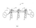
- FIG. 6is a representation of a high-voltage transmission line showing various ways the distributed active impedance-injection modules are to be supported while being directly attached to the HV transmission lines and operating at line voltage as per the embodiments of the invention.
- distributed dynamic-control modulesdistributed active impedance-injection modules
- distributed dynamic-control modulesdistributed active impedance-injection modules
- These distributed dynamic control moduleshave to be directly attached to the HV transmission line and are at line potential while in operation.
- the distributed dynamic-control modulesare enabled to operate by extracting power from the HV transmission line for control and for generating the necessary converter voltages.
- the modulesgenerate and inject voltages at the right phase angle for injection on to the HV transmission line to provide the necessary inductive or capacitive impedance during operation.
- the secondary side of the single turn transformer and all associated circuitryare electrically isolated from the ground. However, one side of the secondary winding is connected to the primary winding to provide a virtual ground or “floating ground” reference.
- the distributed control modulesIn order for the distributed control modules to be successfully accepted by utilities and installed on lines these distributed control modules have to be smart and self-aware, remotely controllable and configurable.
- the modulesshould be of a reasonable weight compared to the line segment over which these are to be installed, even where the modules are suspended in an insulated fashion from the towers or are supported by additional support structures. These should also have a low wind resistance to reduce the effect of wind loading on the line/tower/special support structure employed.
- all the electronic components and circuits of the moduleshould have very high reliability to reduce the probability of down times due to failure of the modules/components used therein.
- the invention disclosedis generally directed at providing very high-reliability distributed active control capability for power-flow balancing across the multiple high-voltage lines used for power transmission on the high-power grid system that overcomes the issues of the prior art implementations.
- the inventionuses of a plurality of secondary windings with individual voltage converters that are used to generate voltages of the correct polarity and amplitude to be impressed on the high-voltage power-lines.
- the distributed impedance-injection modulescomprising the plurality of injector blocks that enable generation and injection of the right impedance, inductive or capacitive as required, for dynamic line balancing is disclosed. These distributed impedance injection-modules are direct attached to the HV transmission lines at the towers or at special support structures that can help support the weight of the modules.
- the distributed modulethat is to be attached to the HV transmission line at the secondary side of the transformer and all associated circuitry are electrically at line voltage and isolated from ground.
- One side of the secondary windingis connected to the primary winding to provide a virtual ground or “floating ground” reference.
- each injecting an impedance onto the HV transmission linethe total necessary cumulative voltage for correction of the phase angle can be impressed on the segment of the grid without unduly stressing the circuits associated with each of the secondary windings of the distributed impedance-injector module.
- the current inventionaddresses the advantages and features of the distributed module with multiple secondary windings and associated core segments with associated voltage converters/inverters to address the problem of actively injecting inductive and capacitive impedances in line segments.
- the voltage converter or simply converter 405may be of any appropriate design, as such devices of various designs are well known in the art. Typically such devices are configured to inject an inductive load onto the high voltage transmission line, and may also have the capability of injecting a capacitive load on the transmission for power factor control, and may further be capable of controlling harmonic content in the high voltage transmission line. Such devices are also known by other names, such as by way of example, inverters or converters/inverters.
- An exemplary device of this general typeis the combination of the inverter 71 and energy storage 74 of U.S. Pat. No. 7,105,952, though many other examples of such devices are well known. These devices typically act as active impedances to controllably impose the desired impedance onto the high voltage transmission line. Also preferably the controller 410 used in the preferred embodiments includes a transceiver for receiving control signals and reporting on high voltage transmission line conditions, etc.
- the added extra redundant distributed active-impedance control modulesprovide an additional layer of “system” reliability over and above the unit reliability. This in turn results in distributed injection modules of high reliability, capable of providing very high system reliability, acceptable to the utilities.
- the use of the distributed impedance-injection modulesare enablers for providing the capability to balance the power transmitted over the HV-transmission-lines of the power grid.
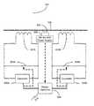
- FIG. 4is a block diagram 400 of a first embodiment of the current invention having a plurality of injector blocks. Each injector block is coupled to the HV transmission line via a secondary winding of a single-turn transformer.
- the FIG. 4shows two exemplary injector blocks 400 A and 400 B.
- FIG. 5Ashows the schematic of the implementation of the single-turn transformer in FIG. 4 and
- FIG. 5Cshows the cross section of the single-turn transformer.
- the exemplary injector blocks 400 A and 400 Bare shown, each having a single turn of primary winding transformer 401 A and 401 B.
- the primary winding of these transformerscomprise the HV transmission line 108 .
- the secondary winding 401 A- 2 of the injection transformer 401 A and the secondary winding 401 B- 2 of the injection transformer 401 B shown in FIGS. 5A and 5Care electrically isolated from ground and the primary winding but inductively coupled to the primary winding 108 using independent un-gapped cores 407 A and 407 B as shown in FIG. 5A .
- the secondary circuits of each of the injection transformers 401 A and 401 Bcomprise power-electronic circuits for generation and injection of the inductive and capacitive impedances (or equivalent voltages) onto the HV transmission line 108 .
- the secondary winding circuit of the injector block 400 A having the single-turn injection transformer 401 Acomprises of a shorting switch 304 A, a power converter 405 A for generating the necessary voltages and currents at the appropriate phase angle for injecting on to the HV transmission line 108 via the single-turn injection transformer 401 A.
- a controller 406 Ais enabled to sense the HV transmission line 108 current and voltage characteristics through a sensor and power-supply transformer 302 A connected to a sensor and power supply module 303 A.
- the controller 406 Aprovides the needed control instructions to the power converter 405 A to generate the needed injection voltages to be impressed on the HV transmission line for power-flow control.
- the controller 406 Ais also enabled to sense via the sensor and power supply transformer 302 A and the connected sensor and power supply module 303 A, when over-current conditions exist in the HV transmission line and to provide instruction to the switch 304 A to short the secondary winding 401 A- 2 of the injection transformer 401 A. This is done in order to protect the power electronic circuits and components connected to the secondary winding 401 A- 2 of the injection transformer 401 A from damage due to high voltages and currents.
- the sensor and power supply module 303 Aare also enabled to extract power from the line and provide the DC supply voltages needed by the power-electronics circuits connected to the secondary winding 401 A- 2 of the injection transformer 401 A.
- the same set of components and blocksare repeated for the same functionality implemented by the second injector block 400 B.
- a master control block 408coordinates and synchronizes the operation of the secondary controllers 406 A and 406 B to provide the corrective impedance injection.
- the master controller 408also provides the capability for the module containing the plurality of injection blocks for communicating to the outside world as well as other distributed modules, to provide status and control information. The communication capability is also used for external control and configuration of the module.
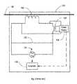
- FIG. 5shows a second alternate embodiment of the disclosed invention having a plurality of secondary windings each associated with an impedance-injector block.
- the two exemplary injection blocks similar to the previous embodiment 400 A and 400 Bare shown in FIG. 5 .
- the exemplary injector blocks 400 A and 400 Bare shown, each have a single-turn of primary winding transformer 401 A and 401 B.
- the primary winding of these transformersis the HV transmission line 108 .
- the secondary winding 401 A- 2 of the injection transformer 401 A and the secondary winding 401 B- 2 of the injection transformer 401 Bare shown in FIG. 5A .
- the cross section of the single-turn transformeris shown in FIG. 5C . (The transformer shape might be different as shown here.
- the secondary windings of the transformersare electrically isolated from ground, being at the HV transmission line voltage, and are inductively coupled to the primary winding 108 using independent un-gapped cores 407 A and 407 B as shown in FIG. 5A .
- the secondary circuit of each of the injection transformers 401 A and 401 Bcomprise power-electronic circuits for generation and injection of the inductive and capacitive impedances on to the HV transmission line 108 .
- Each of the secondary winding circuits of the injector blocks 400 A and 400 Bare similar in structure and as such, the block diagram is explained using the injector block 400 A.
- the injector block 400 Ahas a single-turn injection transformer 401 A, having a shorting switch 304 A across its secondary winding 401 A- 2 and a power converter 405 A for generating the necessary voltages and currents at the appropriate phase angle for injecting on to the HV transmission line 108 via the single-turn injection transformer 401 A coupled to it.
- a master controller 508is common to all the injector blocks and is enabled to sense the HV transmission line 108 current and voltage characteristics through a sensor and power-supply transformer 502 coupled to the HV transmission line 108 via a sensor and power supply module 503 .
- the master controller 508provides the needed control instructions to the power converter 405 A to generate the needed injection voltages to be impressed on the HV transmission line 108 for line balancing.
- the respective converter/inverter controllersmay provide alternate redundant master-controller architectures.
- the controller 508is also enabled to sense via the sensor and power supply transformer 502 and the connected sensor and power supply module 503 when over-current conditions exist in the HV transmission line and to provide instruction to the switch 304 A to short the secondary winding 401 A- 2 shown in FIG. 5A of the injection transformer 401 A in order to protect the power-electronic circuits and components connected to the secondary winding 401 A- 2 of the injection transformer 401 A from damage due to high voltages and currents.
- the sensor and power supply module 503is also enabled to extract power from the line and provide the DC supply voltages needed by the power-electronics circuits connected to the secondary winding 401 A- 2 of the injection transformer 401 A.
- the master controller 508also provides the capability for the module containing the plurality of injection blocks for communication to the outside world to provide status and to be externally controlled and configured for operation.
- FIG. 5B and cross section FIG. 5Dshow an alternate way to implement the single-turn injection transformer 401 C.
- a single non-gapped core 407is enabled to carry the plurality of secondary windings.
- Two secondary windings 401 A- 2 and 401 B- 2are shown as per the exemplary block diagrams in FIG. 4 and FIG. 5 .
- the single-turn injection transformersprovide the coupling necessary to impress the generated impedance on to the HV transmission line 108 .
- each generating a part of the injection voltageallow each injector block, such as 400 A and 400 B of the module to output a portion of the required injectable impedance to control the impedance of the line while enabling the distributed injection module 400 to generate the needed range of injectable impedance (or respective voltage) in a cumulative fashion from the plurality of injector blocks to be impressed on the HV transmission line 108 .
- the power-electronic circuits within the secondary injector blocks 400 A and 400 Bare able to operate without undue stress at voltages that are normal for these components when a plurality of such blocks are used in a module to generate the needed impedance (or respective voltage).
- the use of a plurality of secondary windings with associated injector blocksalso enable lower voltages and currents to be used in the individual injector blocks.
- the multiple secondary windingsare electrically equivalent to a single secondary winding with a multiple of the voltage value of the single winding wherein such a single secondary winding would need a higher power output converter than used in the present invention, with the plurality of secondary windings, to impress the same impedance on the power line.
- a plurality of injector blocks, within an injection module 400can be implemented in an impedance-injection module.
- Each injector blockassociated with a secondary winding of the single-turn transformer and capable of injecting a small portion of the overall inductive or capacitive impedance needed for HV transmission line control.
- the modulecan be used to provide the full cumulative distributed control capability for the line segment of the power grid.
- each injection blockwith its own power-electronic control and converter capability, the weight and the wind cross section of the module may be higher. It should be understood that all the associated circuits of the module are enclosed in a housing, which is suspended insulated from ground at the HV transmission line voltage. Due to weight considerations it is preferable to have these modules suspended from the towers or provide additional support for attachment.
- FIG. 6shows the typical attachment methods 600 possible for supporting the injection modules 400 or injection module 500 connected to the HV-transmission-lines.
- the on-line attachment 601is the typical prior art attachment used for the static modules, which connects the module to the line directly, with no additional support and let the line supports take the weight of the module and the line. Though this is acceptable, this type of attachment is not the preferred one for the injector modules 400 of the current invention.
- the preferred attachment for these injector modules 400 for distributed controlare with additional support as shown. Directly connected by supporting insulators 602 on the HV transmission towers 610 or by using special support structures 611 with insulated supports 603 for providing the distributed module additional weight carrying capability. The use of the above support methods are also oriented towards improved reliability of the structures during extreme climatic disturbances.
Landscapes
- Engineering & Computer Science (AREA)
- Power Engineering (AREA)
- Cable Transmission Systems, Equalization Of Radio And Reduction Of Echo (AREA)
- Dc-Dc Converters (AREA)
- Power Conversion In General (AREA)
Abstract
Description
- 1. The need is to have a distributed module that can generate and supply the required range of inductive and capacitive impedances (generating the necessary leading or lagging voltages with respective to the line current) to the transmission line to provide the necessary control for line balancing.
- 2. Provide the above capability at a reasonable cost point—preferably by using standard off-the-shelf power-electronics components; this means that the secondary winding and associated circuits operate at voltages and current levels normally seen in high-volume power-electronic applications. Using off-the-shelf power electronic components means using general purpose power electronic components that are also manufactured and sold in the normal course of business for other uses.
- 3. The third is the need for reliability of the distributed modules to be high enough to eliminate failures and related replacements to an acceptable level for the Utilities—This is achievable if standard power electronics components, with known reliability can be used in the secondary circuits.
- 4. The final need is to have relatively low weight and wind-related cross section for the module to be attached to the HV transmission line with minimum extra support.
Claims (25)
Priority Applications (10)
| Application Number | Priority Date | Filing Date | Title |
|---|---|---|---|
| US15/069,785US10008317B2 (en) | 2015-12-08 | 2016-03-14 | Voltage or impedance-injection method using transformers with multiple secondary windings for dynamic power flow control |
| US15/345,065US10180696B2 (en) | 2015-12-08 | 2016-11-07 | Distributed impedance injection module for mitigation of the Ferranti effect |
| MX2018006920AMX389011B (en) | 2015-12-08 | 2016-11-16 | VOLTAGE OR IMPEDANCE INJECTION METHOD USING TRANSFORMERS WITH MULTIPLE SECONDARY FANS FOR DYNAMIC POWER FLOW CONTROL. |
| EP16873565.2AEP3387728A4 (en) | 2015-12-08 | 2016-11-16 | METHOD FOR INJECTING VOLTAGE OR IMPEDANCE USING TRANSFORMERS HAVING MULTIPLE SECONDARY WINDINGS FOR DYNAMIC POWER STREAM CONTROL |
| AU2016369278AAU2016369278B2 (en) | 2015-12-08 | 2016-11-16 | Voltage or impedance-injection method using transformers with multiple secondary windings for dynamic power flow control |
| BR112018011543-6ABR112018011543B1 (en) | 2015-12-08 | 2016-11-16 | ACTIVE IMPEDANCE INJECTION MODULE FOR DYNAMIC LINE BALANCING OF A DISTRIBUTED HIGH VOLTAGE TRANSMISSION LINE, IMPROVEMENT FOR IN THE MODULE AND METHOD TO PROVIDE DYNAMIC AND DISTRIBUTED LINE BALANCING OF A HIGH VOLTAGE TRANSMISSION LINE |
| KR1020187019403AKR20180108581A (en) | 2015-12-08 | 2016-11-16 | A voltage or impedance-injection method using transformers having a plurality of secondary windings for dynamic power flow control |
| CN201680081388.XACN108780995B (en) | 2015-12-08 | 2016-11-16 | Voltage or Impedance Injection Method for Dynamic Power Flow Control Using Transformers with Multiple Secondary Windings |
| PCT/US2016/062358WO2017099966A1 (en) | 2015-12-08 | 2016-11-16 | Voltage or impedance-injection method using transformers with multiple secondary windings for dynamic power flow control |
| US15/981,616US10283254B2 (en) | 2015-12-08 | 2018-05-16 | Voltage or impedance-injection method using transformers with multiple secondary windings for dynamic power flow control |
Applications Claiming Priority (2)
| Application Number | Priority Date | Filing Date | Title |
|---|---|---|---|
| US201562264744P | 2015-12-08 | 2015-12-08 | |
| US15/069,785US10008317B2 (en) | 2015-12-08 | 2016-03-14 | Voltage or impedance-injection method using transformers with multiple secondary windings for dynamic power flow control |
Related Parent Applications (1)
| Application Number | Title | Priority Date | Filing Date |
|---|---|---|---|
| US15/055,422Continuation-In-PartUS10418814B2 (en) | 2015-12-08 | 2016-02-26 | Transformers with multi-turn primary windings for dynamic power flow control |
Related Child Applications (2)
| Application Number | Title | Priority Date | Filing Date |
|---|---|---|---|
| US15/345,065Continuation-In-PartUS10180696B2 (en) | 2015-12-08 | 2016-11-07 | Distributed impedance injection module for mitigation of the Ferranti effect |
| US15/981,616ContinuationUS10283254B2 (en) | 2015-12-08 | 2018-05-16 | Voltage or impedance-injection method using transformers with multiple secondary windings for dynamic power flow control |
Publications (2)
| Publication Number | Publication Date |
|---|---|
| US20170163245A1 US20170163245A1 (en) | 2017-06-08 |
| US10008317B2true US10008317B2 (en) | 2018-06-26 |
Family
ID=58799915
Family Applications (2)
| Application Number | Title | Priority Date | Filing Date |
|---|---|---|---|
| US15/069,785Active2036-04-15US10008317B2 (en) | 2015-12-08 | 2016-03-14 | Voltage or impedance-injection method using transformers with multiple secondary windings for dynamic power flow control |
| US15/981,616ActiveUS10283254B2 (en) | 2015-12-08 | 2018-05-16 | Voltage or impedance-injection method using transformers with multiple secondary windings for dynamic power flow control |
Family Applications After (1)
| Application Number | Title | Priority Date | Filing Date |
|---|---|---|---|
| US15/981,616ActiveUS10283254B2 (en) | 2015-12-08 | 2018-05-16 | Voltage or impedance-injection method using transformers with multiple secondary windings for dynamic power flow control |
Country Status (8)
| Country | Link |
|---|---|
| US (2) | US10008317B2 (en) |
| EP (1) | EP3387728A4 (en) |
| KR (1) | KR20180108581A (en) |
| CN (1) | CN108780995B (en) |
| AU (1) | AU2016369278B2 (en) |
| BR (1) | BR112018011543B1 (en) |
| MX (1) | MX389011B (en) |
| WO (1) | WO2017099966A1 (en) |
Cited By (22)
| Publication number | Priority date | Publication date | Assignee | Title |
|---|---|---|---|---|
| US11107661B2 (en) | 2019-07-09 | 2021-08-31 | COMET Technologies USA, Inc. | Hybrid matching network topology |
| US11114279B2 (en)* | 2019-06-28 | 2021-09-07 | COMET Technologies USA, Inc. | Arc suppression device for plasma processing equipment |
| US11290080B2 (en) | 2017-11-29 | 2022-03-29 | COMET Technologies USA, Inc. | Retuning for impedance matching network control |
| US11373844B2 (en) | 2020-09-28 | 2022-06-28 | COMET Technologies USA, Inc. | Systems and methods for repetitive tuning of matching networks |
| US11521832B2 (en) | 2020-01-10 | 2022-12-06 | COMET Technologies USA, Inc. | Uniformity control for radio frequency plasma processing systems |
| US11527385B2 (en) | 2021-04-29 | 2022-12-13 | COMET Technologies USA, Inc. | Systems and methods for calibrating capacitors of matching networks |
| US11596309B2 (en) | 2019-07-09 | 2023-03-07 | COMET Technologies USA, Inc. | Hybrid matching network topology |
| US11605527B2 (en) | 2020-01-20 | 2023-03-14 | COMET Technologies USA, Inc. | Pulsing control match network |
| US11657980B1 (en) | 2022-05-09 | 2023-05-23 | COMET Technologies USA, Inc. | Dielectric fluid variable capacitor |
| US11670488B2 (en) | 2020-01-10 | 2023-06-06 | COMET Technologies USA, Inc. | Fast arc detecting match network |
| US11830708B2 (en) | 2020-01-10 | 2023-11-28 | COMET Technologies USA, Inc. | Inductive broad-band sensors for electromagnetic waves |
| US11887820B2 (en) | 2020-01-10 | 2024-01-30 | COMET Technologies USA, Inc. | Sector shunts for plasma-based wafer processing systems |
| US11923175B2 (en) | 2021-07-28 | 2024-03-05 | COMET Technologies USA, Inc. | Systems and methods for variable gain tuning of matching networks |
| US11961711B2 (en) | 2020-01-20 | 2024-04-16 | COMET Technologies USA, Inc. | Radio frequency match network and generator |
| US12002611B2 (en) | 2019-08-28 | 2024-06-04 | COMET Technologies USA, Inc. | High power low frequency coils |
| US12027351B2 (en) | 2020-01-10 | 2024-07-02 | COMET Technologies USA, Inc. | Plasma non-uniformity detection |
| US12040139B2 (en) | 2022-05-09 | 2024-07-16 | COMET Technologies USA, Inc. | Variable capacitor with linear impedance and high voltage breakdown |
| US12051549B2 (en) | 2022-08-02 | 2024-07-30 | COMET Technologies USA, Inc. | Coaxial variable capacitor |
| US12057296B2 (en) | 2021-02-22 | 2024-08-06 | COMET Technologies USA, Inc. | Electromagnetic field sensing device |
| US12132435B2 (en) | 2022-10-27 | 2024-10-29 | COMET Technologies USA, Inc. | Method for repeatable stepper motor homing |
| US12243717B2 (en) | 2022-04-04 | 2025-03-04 | COMET Technologies USA, Inc. | Variable reactance device having isolated gate drive power supplies |
| US12288673B2 (en) | 2017-11-29 | 2025-04-29 | COMET Technologies USA, Inc. | Retuning for impedance matching network control |
Families Citing this family (11)
| Publication number | Priority date | Publication date | Assignee | Title |
|---|---|---|---|---|
| US10097037B2 (en) | 2016-02-11 | 2018-10-09 | Smart Wires Inc. | System and method for distributed grid control with sub-cyclic local response capability |
| CN107482642A (en)* | 2017-08-02 | 2017-12-15 | 华中科技大学 | A plug-and-play active series compensator |
| CN107332243A (en)* | 2017-08-02 | 2017-11-07 | 华中科技大学 | A kind of multi-functional electric energy quality controller of plug and play |
| GB2575449A (en)* | 2018-07-09 | 2020-01-15 | Bristol Bluegreen Ltd | Voltage control device |
| US11121551B2 (en)* | 2018-08-23 | 2021-09-14 | Smart Wires Inc. | Modular time synchronized injection modules |
| US10886749B2 (en)* | 2018-10-23 | 2021-01-05 | Hewlett Packard Enterprise Development Lp | Synchronized startup of power supplies in electrical systems |
| US11411404B2 (en)* | 2019-11-22 | 2022-08-09 | Smart Wires Inc. | Use of the unused duration injection units in an array to reduce oscillations during impedance injection for corrections of problems |
| US11641102B2 (en)* | 2020-03-10 | 2023-05-02 | Smart Wires Inc. | Modular FACTS devices with external fault current protection within the same impedance injection module |
| US11735922B2 (en)* | 2020-08-28 | 2023-08-22 | Smart Wires Inc. | Temporal balancing of electrical stress on FACTS devices in FACTS based distributed impedance injection units |
| US11942266B1 (en)* | 2022-03-11 | 2024-03-26 | Uber Technologies, Inc. | Electrical power distribution and monitoring system for data |
| FR3156256A1 (en)* | 2023-12-05 | 2025-06-06 | Nexans | Method for balancing the phases of a polyphase electric current supply, and system for its implementation |
Citations (123)
| Publication number | Priority date | Publication date | Assignee | Title |
|---|---|---|---|---|
| US2237812A (en) | 1940-02-23 | 1941-04-08 | Gen Electric | Portable unit substation |
| US2551841A (en) | 1946-11-27 | 1951-05-08 | Westinghouse Electric Corp | Electrical apparatus |
| US3556310A (en) | 1968-05-27 | 1971-01-19 | Jack Loukotsky | Prefabricated modular power substation |
| US3704001A (en) | 1970-11-17 | 1972-11-28 | Clifford E Sloop | Mounting bracket |
| US3750992A (en) | 1972-06-26 | 1973-08-07 | E Johnson | Transformer mounting assembly |
| US3913003A (en) | 1973-10-31 | 1975-10-14 | Siemens Ag | Compact converter building block system |
| US4025824A (en) | 1976-02-12 | 1977-05-24 | Cheatham Harry P | Transformer support rack |
| US4057736A (en) | 1974-09-13 | 1977-11-08 | Jeppson Morris R | Electrical power generation and distribution system |
| US4103853A (en) | 1976-12-22 | 1978-08-01 | Mcgraw-Edison Company | Aluminum cluster mount |
| US4164345A (en) | 1978-02-03 | 1979-08-14 | Arnold William L | Safety cradle for transformer repair |
| US4200899A (en) | 1976-07-16 | 1980-04-29 | Grinshtein Vladimir Y | Outdoor high-voltage switchgear |
| US4277639A (en) | 1979-03-27 | 1981-07-07 | Asea Aktiebolag | High-voltage installation including heavy electrical apparatus suspended by insulator means |
| US4286207A (en) | 1980-04-14 | 1981-08-25 | Westinghouse Electric Corp. | High-power AC voltage stabilizer |
| US4323722A (en) | 1980-09-24 | 1982-04-06 | The United States Of America As Represented By The United States Department Of Energy | Overhead electric power transmission line jumpering system for bundles of five or more subconductors |
| US4367512A (en) | 1978-11-24 | 1983-01-04 | Kabushiki Kaisha Meidensha | Transportable power supply substation |
| US4514950A (en) | 1981-11-27 | 1985-05-07 | Goodson Jr Albert A | Building framing system and method |
| US4562360A (en) | 1981-10-13 | 1985-12-31 | Mitsubishi Denki Kabushiki Kaisha | Mobile substation |
| US4577826A (en) | 1983-07-11 | 1986-03-25 | Asea Aktiebolag | Stand structure for supporting electric high voltage equipment |
| CH660094A5 (en) | 1978-10-27 | 1987-03-13 | Hazemeijer Bv | SUBSTATION AND MAIN DISTRIBUTION STATION FOR DISTRIBUTION OF ELECTRICAL ENERGY. |
| US4710850A (en) | 1986-02-19 | 1987-12-01 | Siemens Aktiengesellschaft | Tower design for high-voltage systems |
| US4821138A (en) | 1986-05-23 | 1989-04-11 | Sumitomo Electric Industries, Ltd. | Monitoring device for overhead power transmission system |
| US4903927A (en) | 1988-09-29 | 1990-02-27 | Aluma-Form, Inc. | Electrical equipment cluster mount |
| US5006846A (en) | 1987-11-12 | 1991-04-09 | Granville J Michael | Power transmission line monitoring system |
| US5023768A (en) | 1989-11-24 | 1991-06-11 | Varian Associates, Inc. | High voltage high power DC power supply |
| US5032738A (en) | 1986-01-22 | 1991-07-16 | Vithayathil John J | Scheme for rapid adjustment of network impedance |
| US5193774A (en) | 1992-05-26 | 1993-03-16 | Rogers J W | Mounting bracket apparatus |
| US5461300A (en) | 1993-03-30 | 1995-10-24 | Electric Power Research Institute, Inc. | Phase angle regulating transformer with a single core per phase |
| US5469044A (en) | 1995-01-05 | 1995-11-21 | Westinghouse Electric Corporation | Transmission line power flow controller with unequal advancement and retardation of transmission angle |
| US5610501A (en) | 1995-02-01 | 1997-03-11 | Westinghouse Electric Corporation | Dynamic power and voltage regulator for an ac transmission line |
| US5648888A (en) | 1995-12-27 | 1997-07-15 | Hydro-Quebec | Power distribution substation |
| US5844462A (en) | 1996-04-29 | 1998-12-01 | Alliedsignal Inc. | Magnetic core-coil assembly for spark ignition systems |
| US5884886A (en) | 1994-02-26 | 1999-03-23 | Asea Brown Boveri Ag | Support frame for a structural component |
| US5886888A (en) | 1995-04-27 | 1999-03-23 | Mitsubishi Denki Kabushiki Kaisha | Voltage source type power converting apparatus |
| US5986617A (en) | 1998-08-31 | 1999-11-16 | Lucent Technologies | Multiband antenna matching unit |
| US6088249A (en) | 1997-12-02 | 2000-07-11 | Power Circuit Innovations, Inc. | Frequency modulated ballast with loosely coupled transformer |
| US6134105A (en) | 1998-01-06 | 2000-10-17 | Lueker; Mark David | Portable command center |
| US6147581A (en) | 1999-11-17 | 2000-11-14 | Asea Brown Boveri Inc. | Universal transformer tank for pole-mounted distribution transformers |
| US6215653B1 (en) | 1999-07-15 | 2001-04-10 | Aep Resources Services Company | Modular electrical substation and method of constructing same |
| US6233137B1 (en) | 2000-05-25 | 2001-05-15 | Mathias Kolos | Compact power distribution substation |
| US6335613B1 (en) | 2000-12-04 | 2002-01-01 | Abb T&D Technology Ltd. | Versatile power flow transformers for compensating power flow in a transmission line |
| US20020005668A1 (en) | 1998-12-04 | 2002-01-17 | Pierre Couture | Power flow management in an electric power grid |
| US20020042696A1 (en) | 1999-04-09 | 2002-04-11 | Public Service Company Of New Mexico | Utility station automated design system and method |
| JP2002199563A (en) | 2000-12-26 | 2002-07-12 | Hitachi Cable Ltd | How to branch overhead power lines |
| US20030006652A1 (en) | 1998-12-04 | 2003-01-09 | Hydro-Quebec | Switching apparatus and method for a segment of an electric power line |
| US20030098768A1 (en) | 2001-11-23 | 2003-05-29 | Roland Hoffmann | Winding for a transformer or a coil and method for producing the winding |
| US20040217836A1 (en) | 2003-04-30 | 2004-11-04 | Marc-Antoine Archambault | Distribution transformer |
| US6831377B2 (en) | 2000-05-03 | 2004-12-14 | University Of Southern California | Repetitive power pulse generator with fast rising pulse |
| JP2005045888A (en) | 2003-07-25 | 2005-02-17 | Toshiba Corp | Power distribution tower |
| US20050052801A1 (en) | 2003-09-05 | 2005-03-10 | Ghali Gamal A. | Method for tapping a high voltage transmission line and substation using the same |
| US20050073200A1 (en) | 2003-10-03 | 2005-04-07 | Divan Deepakraj M. | Distributed floating series active impedances for power transmission systems |
| US20050194944A1 (en) | 2004-03-04 | 2005-09-08 | Folts Douglas C. | Dynamic reactive compensation system and method |
| US20050205726A1 (en) | 2003-02-21 | 2005-09-22 | Areva T&D Sa | Articulated support with lateral movement for high-voltage or medium-voltage electrical plant |
| US20060085097A1 (en) | 2004-10-16 | 2006-04-20 | Courtney Thomas A | Power distribution substation |
| US20070135972A1 (en) | 2005-10-07 | 2007-06-14 | Jay Jacobson | Method and system for improving the efficiency and reliability of a power grid |
| US20070250217A1 (en) | 2006-04-25 | 2007-10-25 | Korea Electric Power Corporation | System and method for automatically operating upfc (unified power flow controller) connected to scada (supervisory control and data acquisition) |
| US20080103737A1 (en) | 2006-10-31 | 2008-05-01 | Yoon Jong-Su | Simulation system for facts connected online to scada system |
| US20080157728A1 (en) | 2006-08-04 | 2008-07-03 | Mitsubishi Electric Corporation | Reactive-power control apparatus and reactive-power compensator using the same |
| WO2008082820A1 (en) | 2006-12-28 | 2008-07-10 | 3M Innovative Properties Company | Overhead electrical power transmission line |
| US20080177425A1 (en) | 2005-06-24 | 2008-07-24 | Abb Research Ltd | Damping electromechanical oscillations in power systems |
| US20080278976A1 (en) | 2007-05-11 | 2008-11-13 | Schneider Robert S | Dynamic voltage sag correction |
| US20080310069A1 (en) | 2005-01-31 | 2008-12-18 | Deepakraj Malhar Divan | Systems and Methods for Distributed Series Compensation of Power Lines Using Passive Devices |
| US20090243876A1 (en) | 2005-09-16 | 2009-10-01 | Jean-Louis Lilien | Device, system and method for real-time monitoring of overhead power lines |
| US20090281679A1 (en) | 2008-05-09 | 2009-11-12 | Taft Jeffrey D | Intelligent monitoring of an electrical utility grid |
| US20100026275A1 (en) | 2007-02-20 | 2010-02-04 | Abb Limited | Flux control system for active voltage conditioning |
| US20100177450A1 (en) | 2009-01-12 | 2010-07-15 | Grid Logic | Method and devices for stabilizing electric grid power |
| US20100213765A1 (en) | 2007-09-26 | 2010-08-26 | Siemens Aktiengesellschaft | Energy supply |
| US7834736B1 (en) | 2009-07-31 | 2010-11-16 | Abb Technology Ag | Dry type pole-mounted transformer |
| US20100302744A1 (en) | 2009-05-29 | 2010-12-02 | Rosendin Electric, Inc. | Various methods and apparatuses for an integrated power distribution platform |
| US20110060474A1 (en) | 2009-09-04 | 2011-03-10 | Voltwerk Electronics Gmbh | Power control device for a power grid, comprising a control unit for controlling an energy flow between the power generation unit, the energy storage unit, the consumer unit and/or the power grid |
| US7932621B1 (en) | 2010-01-28 | 2011-04-26 | James Patrick Spellman | Method and apparatus for an integrated wind-solar energy system utilizing an existing wind turbine infrastructure |
| US20110095162A1 (en) | 2009-04-06 | 2011-04-28 | Pelco Products, Inc. | Cable retainer for utility pole base |
| US20110106321A1 (en) | 2009-11-03 | 2011-05-05 | Spirae, Inc. | Dynamic distributed power grid control system |
| US20110172837A1 (en) | 2007-08-28 | 2011-07-14 | Forbes Jr Joseph W | System and method for estimating and providing dispatchable operating reserve energy capacity through use of active load management |
| KR101053514B1 (en) | 2011-05-20 | 2011-08-03 | 티앤제이건설 주식회사 | Jumper wire connection fixing device for overhead transmission line |
| US20120105023A1 (en) | 2010-10-27 | 2012-05-03 | Satcon Technology Corporation | Automatic ac bus voltage regulation for power distribution grids |
| US20120146335A1 (en) | 2010-12-08 | 2012-06-14 | Northern Power Systems, Inc. | Wind Power Unit Having an Underslung Transformer |
| US20120205981A1 (en) | 2009-09-15 | 2012-08-16 | The University Of Western Ontario | Utilization of distributed generator inverters as statcom |
| US8270558B2 (en) | 2007-09-10 | 2012-09-18 | St-Ericsson Sa | Electronic device, barrel shifter unit and method of barrel shifting |
| US20120242150A1 (en) | 2010-08-04 | 2012-09-27 | Kunihiro Ukai | Power supply system, control device of power supply system, operation method of power supply system, and control method of power supply system |
| US20120255920A1 (en) | 2011-04-11 | 2012-10-11 | Abb Technology Ag | Electrical equipment mounting frame |
| US20120293920A1 (en) | 2009-10-20 | 2012-11-22 | Abb Technology Ltd | System having electrical equipment integrated on a structure and a method for isolation of electrical equipment thereof |
| US20130002032A1 (en) | 2011-06-28 | 2013-01-03 | Shigeki Mori | Power grid operation control system, device, and method |
| US20130033103A1 (en) | 2011-08-02 | 2013-02-07 | Mcjunkin Samuel T | Systems and Methods For Distributed Impedance Compensation In Subsea Power Distribution |
| US20130044407A1 (en) | 2011-08-16 | 2013-02-21 | Lsis Co., Ltd. | Solid insulated switchgear |
| US20130094264A1 (en) | 2010-03-15 | 2013-04-18 | Alstom Technolgoy Ltd. | Static var compensator with multilevel converter |
| US8441778B1 (en) | 2010-12-22 | 2013-05-14 | Stephen L. Ashmore | Modular substation feeder assembly |
| US20130128636A1 (en) | 2010-07-30 | 2013-05-23 | Alstom Technology Ltd | HVDC Converter Comprising Fullbridge Cells For Handling A DC Side Short Circuit |
| US20130169044A1 (en) | 2010-09-13 | 2013-07-04 | Aker Susea AS | Stable subsea electric power transmission to run subsea high speed motors |
| US20130182355A1 (en) | 2010-07-28 | 2013-07-18 | Ormazabal Y Cia, S.L.U | Connection device for transformer substation modules |
| US20130184894A1 (en) | 2010-11-08 | 2013-07-18 | Nec Corporation | Electric power grid control system and method for electric power control |
| US8497592B1 (en) | 2011-08-31 | 2013-07-30 | Thomas Jones | Utility pole mountable vertical axis wind turbine |
| US20130200617A1 (en) | 2010-04-06 | 2013-08-08 | GE Energy Power Conversion Tecnology Ltd | Power transmission systems |
| CN103256337A (en) | 2013-04-24 | 2013-08-21 | 中国电力科学研究院 | Electrical equipment support-type damping control system and damper model selecting method and device thereof |
| US20130277082A1 (en) | 2012-04-24 | 2013-10-24 | Elwha LLC, a limited liability company of the State of Delaware | Transmission-line coupled closed-cycle heat transfer device |
| US20130345888A1 (en) | 2012-06-20 | 2013-12-26 | Joseph W. Forbes, Jr. | Method and apparatus for actively managing electric power over an electric power grid |
| US20140025217A1 (en) | 2011-03-25 | 2014-01-23 | Zhuhai Unitech Power Technology Co., Ltd. | Device and method for self-healing control of a multi-level power grid |
| US20140032000A1 (en) | 2012-07-30 | 2014-01-30 | Siemens Corporation | Power System Stabilization Using Distributed Inverters |
| WO2014035881A1 (en) | 2012-08-28 | 2014-03-06 | Smart Wire Grid, Inc. | Power line reactance module and applications |
| US20140111297A1 (en) | 2012-10-18 | 2014-04-24 | Manufacturing Systems and Equipment Inc. | Wound transformer core and method of manufacture |
| US20140129195A1 (en) | 2011-06-24 | 2014-05-08 | State Grid Corporation Of China | Real time dynamic physics simulation device of flexible dc transmission system |
| WO2014074956A1 (en) | 2012-11-08 | 2014-05-15 | Cameron D | Modular structural system for solar panel installation |
| US20140132229A1 (en) | 2012-11-02 | 2014-05-15 | North Carolina State University | Static synchronous compensator systems and related methods |
| US20140153383A1 (en) | 2011-06-08 | 2014-06-05 | Socpra Sciences Et Genie S.E.C. | Distributed electrical load management method and system for controlling community loads |
| CN203668968U (en) | 2013-12-18 | 2014-06-25 | 中国能源建设集团安徽省电力设计院 | Support supporting component used for transformer substation outdoor AIS electric equipment |
| WO2014099876A1 (en) | 2012-12-18 | 2014-06-26 | Smart Wire Grid, Inc. | Installation fixture for installing devices on power lines |
| US20140188689A1 (en) | 2012-12-31 | 2014-07-03 | Battelle Memorial Institute | Distributed hierarchical control architecture for integrating smart grid assets during normal and disrupted operations |
| US20140203640A1 (en) | 2011-09-12 | 2014-07-24 | Aker Subsea As | Device for stable subsea electric power transmission to run subsea high speed motors or other subsea loads |
| US20140210213A1 (en) | 2013-01-31 | 2014-07-31 | APR Energy, LLC | Scalable portable modular power plant |
| US8816527B1 (en)* | 2013-03-27 | 2014-08-26 | Smart Wire Grid, Inc. | Phase balancing of power transmission system |
| US20140246914A1 (en) | 2011-09-12 | 2014-09-04 | Alstom Technology Ltd. | Sub-Synchronous Oscillation Damping By Shunt Facts Apparatus |
| US20140247554A1 (en) | 2011-10-07 | 2014-09-04 | Sabic Innovative Plastics Ip B.V. | Inverter housing system |
| US20140268458A1 (en) | 2013-03-14 | 2014-09-18 | Innovolt, Inc. | Systems and methods for detecting and determining sources of power disturbances in connection with effective remediation |
| US20140312859A1 (en) | 2013-03-27 | 2014-10-23 | Smart Wire Grid, Inc. | Phase balancing of power transmission system |
| US8890373B2 (en) | 2011-04-04 | 2014-11-18 | Eaton Corporation | Power distribution systems using distributed current sensing |
| US20150029764A1 (en) | 2012-02-24 | 2015-01-29 | Board Of Trustees Of Michigan State University | Transformer-less unified power flow controller |
| US20150051744A1 (en) | 2013-08-19 | 2015-02-19 | Board Of Trustees Of Michigan State University | Linear Optimal Power Flow System and Method |
| JP2015086692A (en) | 2013-09-27 | 2015-05-07 | 株式会社アークリエイト | Steel structure pile pillar-to-base beam joint integrated method |
| WO2015074538A1 (en) | 2013-11-21 | 2015-05-28 | 国家电网公司 | Automatic unfolding type on-site calibration vehicle for high-voltage transformers |
| US20150184415A1 (en) | 2013-01-10 | 2015-07-02 | Kevin M. Bushore | Methods and apparatuses of supporting and bracing a utility pole |
| WO2015119789A1 (en) | 2014-02-07 | 2015-08-13 | Smart Wire Grid, Inc. | Detecting geomagnetically induced currents with powerline devices |
| US20160036341A1 (en) | 2014-07-31 | 2016-02-04 | Korea University Research And Business Foundation | Power grid frequency flexible operation system and method using the same |
| US20170163036A1 (en)* | 2015-12-08 | 2017-06-08 | Smart Wires Inc. | Transformers with Multi-Turn Primary Windings for Dynamic Power Flow Control |
| US20170169928A1 (en)* | 2015-12-10 | 2017-06-15 | Smart Wires Inc. | Power Transmission Tower Mounted Series Injection Transformer |
Family Cites Families (2)
| Publication number | Priority date | Publication date | Assignee | Title |
|---|---|---|---|---|
| US9048649B2 (en) | 2012-03-20 | 2015-06-02 | The Boeing Company | Method and apparatus for anti-icing and deicing power transmission lines |
| US9478351B2 (en) | 2013-05-24 | 2016-10-25 | Keithley Instruments, Inc. | Isolation transformer for use in isolated DC-to-DC switching power supply |
- 2016
- 2016-03-14USUS15/069,785patent/US10008317B2/enactiveActive
- 2016-11-16EPEP16873565.2Apatent/EP3387728A4/enactivePending
- 2016-11-16AUAU2016369278Apatent/AU2016369278B2/enactiveActive
- 2016-11-16WOPCT/US2016/062358patent/WO2017099966A1/ennot_activeCeased
- 2016-11-16BRBR112018011543-6Apatent/BR112018011543B1/enactiveIP Right Grant
- 2016-11-16KRKR1020187019403Apatent/KR20180108581A/ennot_activeWithdrawn
- 2016-11-16MXMX2018006920Apatent/MX389011B/enunknown
- 2016-11-16CNCN201680081388.XApatent/CN108780995B/enactiveActive
- 2018
- 2018-05-16USUS15/981,616patent/US10283254B2/enactiveActive
Patent Citations (168)
| Publication number | Priority date | Publication date | Assignee | Title |
|---|---|---|---|---|
| US2237812A (en) | 1940-02-23 | 1941-04-08 | Gen Electric | Portable unit substation |
| US2551841A (en) | 1946-11-27 | 1951-05-08 | Westinghouse Electric Corp | Electrical apparatus |
| US3556310A (en) | 1968-05-27 | 1971-01-19 | Jack Loukotsky | Prefabricated modular power substation |
| US3704001A (en) | 1970-11-17 | 1972-11-28 | Clifford E Sloop | Mounting bracket |
| US3750992A (en) | 1972-06-26 | 1973-08-07 | E Johnson | Transformer mounting assembly |
| US3913003A (en) | 1973-10-31 | 1975-10-14 | Siemens Ag | Compact converter building block system |
| US4057736A (en) | 1974-09-13 | 1977-11-08 | Jeppson Morris R | Electrical power generation and distribution system |
| US4025824A (en) | 1976-02-12 | 1977-05-24 | Cheatham Harry P | Transformer support rack |
| US4200899A (en) | 1976-07-16 | 1980-04-29 | Grinshtein Vladimir Y | Outdoor high-voltage switchgear |
| US4103853A (en) | 1976-12-22 | 1978-08-01 | Mcgraw-Edison Company | Aluminum cluster mount |
| US4164345A (en) | 1978-02-03 | 1979-08-14 | Arnold William L | Safety cradle for transformer repair |
| CH660094A5 (en) | 1978-10-27 | 1987-03-13 | Hazemeijer Bv | SUBSTATION AND MAIN DISTRIBUTION STATION FOR DISTRIBUTION OF ELECTRICAL ENERGY. |
| US4367512A (en) | 1978-11-24 | 1983-01-04 | Kabushiki Kaisha Meidensha | Transportable power supply substation |
| US4277639A (en) | 1979-03-27 | 1981-07-07 | Asea Aktiebolag | High-voltage installation including heavy electrical apparatus suspended by insulator means |
| US4286207A (en) | 1980-04-14 | 1981-08-25 | Westinghouse Electric Corp. | High-power AC voltage stabilizer |
| US4323722A (en) | 1980-09-24 | 1982-04-06 | The United States Of America As Represented By The United States Department Of Energy | Overhead electric power transmission line jumpering system for bundles of five or more subconductors |
| US4562360A (en) | 1981-10-13 | 1985-12-31 | Mitsubishi Denki Kabushiki Kaisha | Mobile substation |
| US4514950A (en) | 1981-11-27 | 1985-05-07 | Goodson Jr Albert A | Building framing system and method |
| US4577826A (en) | 1983-07-11 | 1986-03-25 | Asea Aktiebolag | Stand structure for supporting electric high voltage equipment |
| US5032738A (en) | 1986-01-22 | 1991-07-16 | Vithayathil John J | Scheme for rapid adjustment of network impedance |
| US4710850A (en) | 1986-02-19 | 1987-12-01 | Siemens Aktiengesellschaft | Tower design for high-voltage systems |
| US4821138A (en) | 1986-05-23 | 1989-04-11 | Sumitomo Electric Industries, Ltd. | Monitoring device for overhead power transmission system |
| US5006846A (en) | 1987-11-12 | 1991-04-09 | Granville J Michael | Power transmission line monitoring system |
| US4903927A (en) | 1988-09-29 | 1990-02-27 | Aluma-Form, Inc. | Electrical equipment cluster mount |
| US5023768A (en) | 1989-11-24 | 1991-06-11 | Varian Associates, Inc. | High voltage high power DC power supply |
| US5193774A (en) | 1992-05-26 | 1993-03-16 | Rogers J W | Mounting bracket apparatus |
| US5461300A (en) | 1993-03-30 | 1995-10-24 | Electric Power Research Institute, Inc. | Phase angle regulating transformer with a single core per phase |
| US5884886A (en) | 1994-02-26 | 1999-03-23 | Asea Brown Boveri Ag | Support frame for a structural component |
| US5469044A (en) | 1995-01-05 | 1995-11-21 | Westinghouse Electric Corporation | Transmission line power flow controller with unequal advancement and retardation of transmission angle |
| US5610501A (en) | 1995-02-01 | 1997-03-11 | Westinghouse Electric Corporation | Dynamic power and voltage regulator for an ac transmission line |
| US5886888A (en) | 1995-04-27 | 1999-03-23 | Mitsubishi Denki Kabushiki Kaisha | Voltage source type power converting apparatus |
| US5648888A (en) | 1995-12-27 | 1997-07-15 | Hydro-Quebec | Power distribution substation |
| US5844462A (en) | 1996-04-29 | 1998-12-01 | Alliedsignal Inc. | Magnetic core-coil assembly for spark ignition systems |
| US6088249A (en) | 1997-12-02 | 2000-07-11 | Power Circuit Innovations, Inc. | Frequency modulated ballast with loosely coupled transformer |
| US6134105A (en) | 1998-01-06 | 2000-10-17 | Lueker; Mark David | Portable command center |
| US5986617A (en) | 1998-08-31 | 1999-11-16 | Lucent Technologies | Multiband antenna matching unit |
| US20020005668A1 (en) | 1998-12-04 | 2002-01-17 | Pierre Couture | Power flow management in an electric power grid |
| US6727604B2 (en) | 1998-12-04 | 2004-04-27 | Hydro-Quebec | Switching apparatus and method for a segment of an electric power line |
| US20030006652A1 (en) | 1998-12-04 | 2003-01-09 | Hydro-Quebec | Switching apparatus and method for a segment of an electric power line |
| US6486569B2 (en) | 1998-12-04 | 2002-11-26 | Hydro-Quebec | Power flow management in an electric power grid |
| US20020042696A1 (en) | 1999-04-09 | 2002-04-11 | Public Service Company Of New Mexico | Utility station automated design system and method |
| US6895373B2 (en) | 1999-04-09 | 2005-05-17 | Public Service Company Of New Mexico | Utility station automated design system and method |
| US6215653B1 (en) | 1999-07-15 | 2001-04-10 | Aep Resources Services Company | Modular electrical substation and method of constructing same |
| US6147581A (en) | 1999-11-17 | 2000-11-14 | Asea Brown Boveri Inc. | Universal transformer tank for pole-mounted distribution transformers |
| US6831377B2 (en) | 2000-05-03 | 2004-12-14 | University Of Southern California | Repetitive power pulse generator with fast rising pulse |
| US6233137B1 (en) | 2000-05-25 | 2001-05-15 | Mathias Kolos | Compact power distribution substation |
| US6335613B1 (en) | 2000-12-04 | 2002-01-01 | Abb T&D Technology Ltd. | Versatile power flow transformers for compensating power flow in a transmission line |
| JP2002199563A (en) | 2000-12-26 | 2002-07-12 | Hitachi Cable Ltd | How to branch overhead power lines |
| US20030098768A1 (en) | 2001-11-23 | 2003-05-29 | Roland Hoffmann | Winding for a transformer or a coil and method for producing the winding |
| US7090176B2 (en) | 2003-02-21 | 2006-08-15 | Areva T&D Sa | Articulated support with lateral movement for high-voltage or medium-voltage electrical plant |
| US20050205726A1 (en) | 2003-02-21 | 2005-09-22 | Areva T&D Sa | Articulated support with lateral movement for high-voltage or medium-voltage electrical plant |
| US6914195B2 (en) | 2003-04-30 | 2005-07-05 | Va Tech Transformateurs Ferranti-Packard (Quebec) Inc. | Distribution transformer |
| US20040217836A1 (en) | 2003-04-30 | 2004-11-04 | Marc-Antoine Archambault | Distribution transformer |
| JP2005045888A (en) | 2003-07-25 | 2005-02-17 | Toshiba Corp | Power distribution tower |
| US7193338B2 (en) | 2003-09-05 | 2007-03-20 | Ghali Gamal A | Method for tapping a high voltage transmission line and substation using the same |
| US20050052801A1 (en) | 2003-09-05 | 2005-03-10 | Ghali Gamal A. | Method for tapping a high voltage transmission line and substation using the same |
| US20050073200A1 (en) | 2003-10-03 | 2005-04-07 | Divan Deepakraj M. | Distributed floating series active impedances for power transmission systems |
| US7105952B2 (en)* | 2003-10-03 | 2006-09-12 | Soft Switching Technologies Corporation | Distributed floating series active impendances for power transmission systems |
| US20050194944A1 (en) | 2004-03-04 | 2005-09-08 | Folts Douglas C. | Dynamic reactive compensation system and method |
| US7091703B2 (en) | 2004-03-04 | 2006-08-15 | American Superconductor Corporation | Dynamic reactive compensation system and method |
| US7352564B2 (en) | 2004-10-16 | 2008-04-01 | Eaton Corporation | Power distribution substation |
| US20060085097A1 (en) | 2004-10-16 | 2006-04-20 | Courtney Thomas A | Power distribution substation |
| US7835128B2 (en)* | 2005-01-31 | 2010-11-16 | Georgia Tech Research Corporation | Systems and methods for distributed series compensation of power lines using passive devices |
| US20080310069A1 (en) | 2005-01-31 | 2008-12-18 | Deepakraj Malhar Divan | Systems and Methods for Distributed Series Compensation of Power Lines Using Passive Devices |
| US8019484B2 (en) | 2005-06-24 | 2011-09-13 | Abb Research Ltd | Damping electromechanical oscillations in power systems |
| US20080177425A1 (en) | 2005-06-24 | 2008-07-24 | Abb Research Ltd | Damping electromechanical oscillations in power systems |
| US20090243876A1 (en) | 2005-09-16 | 2009-10-01 | Jean-Louis Lilien | Device, system and method for real-time monitoring of overhead power lines |
| US7460931B2 (en) | 2005-10-07 | 2008-12-02 | Jay Jacobson | Method and system for improving the efficiency and reliability of a power grid |
| US20070135972A1 (en) | 2005-10-07 | 2007-06-14 | Jay Jacobson | Method and system for improving the efficiency and reliability of a power grid |
| US7642757B2 (en) | 2006-04-25 | 2010-01-05 | Korea Electric Power Corporation | System and method for automatically operating UPFC (unified power flow controller) connected to SCADA (supervisory control and data acquisition) |
| US20070250217A1 (en) | 2006-04-25 | 2007-10-25 | Korea Electric Power Corporation | System and method for automatically operating upfc (unified power flow controller) connected to scada (supervisory control and data acquisition) |
| US20080157728A1 (en) | 2006-08-04 | 2008-07-03 | Mitsubishi Electric Corporation | Reactive-power control apparatus and reactive-power compensator using the same |
| US7688043B2 (en) | 2006-08-04 | 2010-03-30 | Mitsubishi Electric Corporation | Reactive-power control apparatus and reactive-power compensator using the same |
| US20080103737A1 (en) | 2006-10-31 | 2008-05-01 | Yoon Jong-Su | Simulation system for facts connected online to scada system |
| US8249836B2 (en) | 2006-10-31 | 2012-08-21 | Korea Electric Power Corporation | Simulation system for FACTS connected online to SCADA system |
| WO2008082820A1 (en) | 2006-12-28 | 2008-07-10 | 3M Innovative Properties Company | Overhead electrical power transmission line |
| US20100026275A1 (en) | 2007-02-20 | 2010-02-04 | Abb Limited | Flux control system for active voltage conditioning |
| US20080278976A1 (en) | 2007-05-11 | 2008-11-13 | Schneider Robert S | Dynamic voltage sag correction |
| US8996183B2 (en) | 2007-08-28 | 2015-03-31 | Consert Inc. | System and method for estimating and providing dispatchable operating reserve energy capacity through use of active load management |
| US20110172837A1 (en) | 2007-08-28 | 2011-07-14 | Forbes Jr Joseph W | System and method for estimating and providing dispatchable operating reserve energy capacity through use of active load management |
| US8270558B2 (en) | 2007-09-10 | 2012-09-18 | St-Ericsson Sa | Electronic device, barrel shifter unit and method of barrel shifting |
| US20100213765A1 (en) | 2007-09-26 | 2010-08-26 | Siemens Aktiengesellschaft | Energy supply |
| US8310099B2 (en) | 2007-09-26 | 2012-11-13 | Siemens Aktiengesellschaft | Energy supply in which a plurality of components disposed along a transmission route each transform a voltage |
| US20090281679A1 (en) | 2008-05-09 | 2009-11-12 | Taft Jeffrey D | Intelligent monitoring of an electrical utility grid |
| US20100177450A1 (en) | 2009-01-12 | 2010-07-15 | Grid Logic | Method and devices for stabilizing electric grid power |
| US20110095162A1 (en) | 2009-04-06 | 2011-04-28 | Pelco Products, Inc. | Cable retainer for utility pole base |
| US20100302744A1 (en) | 2009-05-29 | 2010-12-02 | Rosendin Electric, Inc. | Various methods and apparatuses for an integrated power distribution platform |
| US8681479B2 (en) | 2009-05-29 | 2014-03-25 | Rosendin Electric, Inc. | Various methods and apparatuses for an integrated power distribution platform |
| US7834736B1 (en) | 2009-07-31 | 2010-11-16 | Abb Technology Ag | Dry type pole-mounted transformer |
| US9099893B2 (en) | 2009-09-04 | 2015-08-04 | Voltwerk Electronics Gmbh | Power control device for a power grid, comprising a control unit for controlling an energy flow between the power generation unit, the energy storage unit, the consumer unit and/or the power grid |
| US20110060474A1 (en) | 2009-09-04 | 2011-03-10 | Voltwerk Electronics Gmbh | Power control device for a power grid, comprising a control unit for controlling an energy flow between the power generation unit, the energy storage unit, the consumer unit and/or the power grid |
| US9325173B2 (en) | 2009-09-15 | 2016-04-26 | The University Of Western Ontario | Utilization of distributed generator inverters as STATCOM |
| US20120205981A1 (en) | 2009-09-15 | 2012-08-16 | The University Of Western Ontario | Utilization of distributed generator inverters as statcom |
| US8896988B2 (en) | 2009-10-20 | 2014-11-25 | Abb Technology Ag | System having electrical equipment integrated on a structure and a method for isolation of electrical equipment thereof |
| US20120293920A1 (en) | 2009-10-20 | 2012-11-22 | Abb Technology Ltd | System having electrical equipment integrated on a structure and a method for isolation of electrical equipment thereof |
| US20150012146A1 (en) | 2009-11-03 | 2015-01-08 | Spirae, Inc. | Dynamic Distributed Power Grid Control System |
| US20130166085A1 (en) | 2009-11-03 | 2013-06-27 | Spirae, Inc. | Dynamic Distributed Power Grid Control System |
| US20110106321A1 (en) | 2009-11-03 | 2011-05-05 | Spirae, Inc. | Dynamic distributed power grid control system |
| US8825218B2 (en) | 2009-11-03 | 2014-09-02 | Spirae, Inc. | Dynamic distributed power grid control system |
| US8401709B2 (en) | 2009-11-03 | 2013-03-19 | Spirae, Inc. | Dynamic distributed power grid control system |
| US7932621B1 (en) | 2010-01-28 | 2011-04-26 | James Patrick Spellman | Method and apparatus for an integrated wind-solar energy system utilizing an existing wind turbine infrastructure |
| US20130094264A1 (en) | 2010-03-15 | 2013-04-18 | Alstom Technolgoy Ltd. | Static var compensator with multilevel converter |
| US9130458B2 (en) | 2010-03-15 | 2015-09-08 | Alstom Technology Ltd. | Static VAR compensator with multilevel converter |
| US9178456B2 (en) | 2010-04-06 | 2015-11-03 | Ge Energy Power Conversion Technology, Ltd. | Power transmission systems |
| US20130200617A1 (en) | 2010-04-06 | 2013-08-08 | GE Energy Power Conversion Tecnology Ltd | Power transmission systems |
| US20130182355A1 (en) | 2010-07-28 | 2013-07-18 | Ormazabal Y Cia, S.L.U | Connection device for transformer substation modules |
| US9246325B2 (en) | 2010-07-28 | 2016-01-26 | Ormazabal Y Cia, S.L.U. | Connection device for transformer substation modules |
| US20130128636A1 (en) | 2010-07-30 | 2013-05-23 | Alstom Technology Ltd | HVDC Converter Comprising Fullbridge Cells For Handling A DC Side Short Circuit |
| US8867244B2 (en) | 2010-07-30 | 2014-10-21 | Alstom Technology Ltd. | HVDC converter including fullbridge cells for handling a DC side short circuit |
| US9124100B2 (en) | 2010-08-04 | 2015-09-01 | Panasonic Intellectual Property Management Co., Ltd. | Power supply system, control device of power supply system, operation method of power supply system, and control method of power supply system |
| US20120242150A1 (en) | 2010-08-04 | 2012-09-27 | Kunihiro Ukai | Power supply system, control device of power supply system, operation method of power supply system, and control method of power supply system |
| US20130169044A1 (en) | 2010-09-13 | 2013-07-04 | Aker Susea AS | Stable subsea electric power transmission to run subsea high speed motors |
| US8680720B2 (en) | 2010-10-27 | 2014-03-25 | Perfect Galaxy International Ltd. | Automatic AC bus voltage regulation for power distribution grids |
| US20120105023A1 (en) | 2010-10-27 | 2012-05-03 | Satcon Technology Corporation | Automatic ac bus voltage regulation for power distribution grids |
| US20130184894A1 (en) | 2010-11-08 | 2013-07-18 | Nec Corporation | Electric power grid control system and method for electric power control |
| US20120146335A1 (en) | 2010-12-08 | 2012-06-14 | Northern Power Systems, Inc. | Wind Power Unit Having an Underslung Transformer |
| US8922038B2 (en) | 2010-12-08 | 2014-12-30 | Northern Power Systems, Inc. | Wind power unit having an underslung transformer |
| US8441778B1 (en) | 2010-12-22 | 2013-05-14 | Stephen L. Ashmore | Modular substation feeder assembly |
| US20140025217A1 (en) | 2011-03-25 | 2014-01-23 | Zhuhai Unitech Power Technology Co., Ltd. | Device and method for self-healing control of a multi-level power grid |
| US8890373B2 (en) | 2011-04-04 | 2014-11-18 | Eaton Corporation | Power distribution systems using distributed current sensing |
| US20120255920A1 (en) | 2011-04-11 | 2012-10-11 | Abb Technology Ag | Electrical equipment mounting frame |
| KR101053514B1 (en) | 2011-05-20 | 2011-08-03 | 티앤제이건설 주식회사 | Jumper wire connection fixing device for overhead transmission line |
| US9185000B2 (en) | 2011-06-08 | 2015-11-10 | Socpra Sciences Et Genie S.E.C. | Overlay network topology system and a network node device therefor |
| US20140153383A1 (en) | 2011-06-08 | 2014-06-05 | Socpra Sciences Et Genie S.E.C. | Distributed electrical load management method and system for controlling community loads |
| US20140129195A1 (en) | 2011-06-24 | 2014-05-08 | State Grid Corporation Of China | Real time dynamic physics simulation device of flexible dc transmission system |
| US9659114B2 (en) | 2011-06-24 | 2017-05-23 | State Grid Corporation Of China | Real time dynamic physics simulation device of flexible DC transmission system |
| US20130002032A1 (en) | 2011-06-28 | 2013-01-03 | Shigeki Mori | Power grid operation control system, device, and method |
| US9124138B2 (en) | 2011-06-28 | 2015-09-01 | Hitachi, Ltd. | Power grid operation control system, device, and method |
| US20130033103A1 (en) | 2011-08-02 | 2013-02-07 | Mcjunkin Samuel T | Systems and Methods For Distributed Impedance Compensation In Subsea Power Distribution |
| US20130044407A1 (en) | 2011-08-16 | 2013-02-21 | Lsis Co., Ltd. | Solid insulated switchgear |
| US8497592B1 (en) | 2011-08-31 | 2013-07-30 | Thomas Jones | Utility pole mountable vertical axis wind turbine |
| US20140203640A1 (en) | 2011-09-12 | 2014-07-24 | Aker Subsea As | Device for stable subsea electric power transmission to run subsea high speed motors or other subsea loads |
| US20140246914A1 (en) | 2011-09-12 | 2014-09-04 | Alstom Technology Ltd. | Sub-Synchronous Oscillation Damping By Shunt Facts Apparatus |
| US20140247554A1 (en) | 2011-10-07 | 2014-09-04 | Sabic Innovative Plastics Ip B.V. | Inverter housing system |
| US8957752B2 (en) | 2011-10-07 | 2015-02-17 | Sabic Global Technologies B.V. | Inverter housing system |
| US20150029764A1 (en) | 2012-02-24 | 2015-01-29 | Board Of Trustees Of Michigan State University | Transformer-less unified power flow controller |
| US20130277082A1 (en) | 2012-04-24 | 2013-10-24 | Elwha LLC, a limited liability company of the State of Delaware | Transmission-line coupled closed-cycle heat transfer device |
| US9207698B2 (en) | 2012-06-20 | 2015-12-08 | Causam Energy, Inc. | Method and apparatus for actively managing electric power over an electric power grid |
| US20130345888A1 (en) | 2012-06-20 | 2013-12-26 | Joseph W. Forbes, Jr. | Method and apparatus for actively managing electric power over an electric power grid |
| US20140032000A1 (en) | 2012-07-30 | 2014-01-30 | Siemens Corporation | Power System Stabilization Using Distributed Inverters |
| WO2014035881A1 (en) | 2012-08-28 | 2014-03-06 | Smart Wire Grid, Inc. | Power line reactance module and applications |
| US20160036231A1 (en) | 2012-08-28 | 2016-02-04 | Smart Wire Inc. | Power line reactance module and applications |
| US20140111297A1 (en) | 2012-10-18 | 2014-04-24 | Manufacturing Systems and Equipment Inc. | Wound transformer core and method of manufacture |
| US20140132229A1 (en) | 2012-11-02 | 2014-05-15 | North Carolina State University | Static synchronous compensator systems and related methods |
| US9331482B2 (en) | 2012-11-02 | 2016-05-03 | North Carolina State University | Static synchronous compensator systems and related methods |
| WO2014074956A1 (en) | 2012-11-08 | 2014-05-15 | Cameron D | Modular structural system for solar panel installation |
| US20150244307A1 (en) | 2012-11-08 | 2015-08-27 | D. Kevin CAMERON | Modular structural system for solar panel installation |
| US20150270689A1 (en) | 2012-12-18 | 2015-09-24 | Smart Wires Inc. | Installation fixture for installing devices on power lines |
| WO2014099876A1 (en) | 2012-12-18 | 2014-06-26 | Smart Wire Grid, Inc. | Installation fixture for installing devices on power lines |
| US20140188689A1 (en) | 2012-12-31 | 2014-07-03 | Battelle Memorial Institute | Distributed hierarchical control architecture for integrating smart grid assets during normal and disrupted operations |
| US20150184415A1 (en) | 2013-01-10 | 2015-07-02 | Kevin M. Bushore | Methods and apparatuses of supporting and bracing a utility pole |
| US8872366B2 (en) | 2013-01-31 | 2014-10-28 | APR Energy, LLC | Scalable portable modular power plant |
| US20140210213A1 (en) | 2013-01-31 | 2014-07-31 | APR Energy, LLC | Scalable portable modular power plant |
| US20140268458A1 (en) | 2013-03-14 | 2014-09-18 | Innovolt, Inc. | Systems and methods for detecting and determining sources of power disturbances in connection with effective remediation |
| US8816527B1 (en)* | 2013-03-27 | 2014-08-26 | Smart Wire Grid, Inc. | Phase balancing of power transmission system |
| US20140327305A1 (en) | 2013-03-27 | 2014-11-06 | Smart Wire Grid, Inc. | Phase balancing of power transmission system |
| US20140312859A1 (en) | 2013-03-27 | 2014-10-23 | Smart Wire Grid, Inc. | Phase balancing of power transmission system |
| CN103256337A (en) | 2013-04-24 | 2013-08-21 | 中国电力科学研究院 | Electrical equipment support-type damping control system and damper model selecting method and device thereof |
| US20150051744A1 (en) | 2013-08-19 | 2015-02-19 | Board Of Trustees Of Michigan State University | Linear Optimal Power Flow System and Method |
| JP2015086692A (en) | 2013-09-27 | 2015-05-07 | 株式会社アークリエイト | Steel structure pile pillar-to-base beam joint integrated method |
| WO2015074538A1 (en) | 2013-11-21 | 2015-05-28 | 国家电网公司 | Automatic unfolding type on-site calibration vehicle for high-voltage transformers |
| CN203668968U (en) | 2013-12-18 | 2014-06-25 | 中国能源建设集团安徽省电力设计院 | Support supporting component used for transformer substation outdoor AIS electric equipment |
| US20150226772A1 (en) | 2014-02-07 | 2015-08-13 | Smart Wire Grid, Inc. | Detection of geomagnetically-induced currents with power line-mounted devices |
| WO2015119789A1 (en) | 2014-02-07 | 2015-08-13 | Smart Wire Grid, Inc. | Detecting geomagnetically induced currents with powerline devices |
| US9217762B2 (en)* | 2014-02-07 | 2015-12-22 | Smart Wires Inc. | Detection of geomagnetically-induced currents with power line-mounted devices |
| US20160036341A1 (en) | 2014-07-31 | 2016-02-04 | Korea University Research And Business Foundation | Power grid frequency flexible operation system and method using the same |
| US20170163036A1 (en)* | 2015-12-08 | 2017-06-08 | Smart Wires Inc. | Transformers with Multi-Turn Primary Windings for Dynamic Power Flow Control |
| US20170169928A1 (en)* | 2015-12-10 | 2017-06-15 | Smart Wires Inc. | Power Transmission Tower Mounted Series Injection Transformer |
Non-Patent Citations (34)
| Title |
|---|
| "International Search Report and Written Opinion of the International Searching Authority dated Feb. 2, 2017; International Application No. PCT/US2016/062358", (Feb. 2, 2017). |
| "International Search Report and Written Opinion of the International Searching Authority dated Feb. 2, 2017; International Application No. PCT/US2016/062620", (Feb. 2, 2017). |
| "International Search Report and Written Opinion of the International Searching Authority dated Mar. 2, 2017; International Application No. PCT/US2016/061009", (Mar. 2, 2017). |
| "Invitation of the International Searching Authority to Pay Additional Fees dated Dec. 15, 2016; International Application No. PCT/US2016/061009", (Dec. 15, 2016). |
| "Office Action dated Apr. 6, 2018; U.S. Appl. No. 15/055,422", dated Apr. 6, 2018. |
| "Office Action dated Apr. 6, 2018; U.S. Appl. No. 15/157,726", dated Apr. 6, 2018. |
| "Office Action dated Feb. 9, 2018; U.S. Appl. No. 15/345,065", dated Feb. 9, 2018. |
| "Office Action dated Nov. 3, 2017; U.S. Appl. No. 15/157,726", dated Nov. 3, 2017. |
| Amin, S. M., et al., "Toward a Smart Grid: Power Delivery for the 21st Century", IEEE power & energy magazine, vol. 3, No. 5, (Sep./Oct. 2005), pp. 34-41. |
| Angeladas, Emmanouil , "High Voltage Substations Overview (part 1)", Siemens, (Jan. 24, 2013), pp. 1-8. |
| Aquino-Lugo, Angel A., "Distributed and Decentralized Control of the Power Grid", Ph.D. Dissertation, University of Illinois at Urbana-Champaign, (2010), 172 pp. total. |
| Dash, P. K., et al., "Digital Protection of Power Transmission Lines in the Presence of Series Connected FACTS Devices", IEEE Power Engineering Society Winter Meeting, (2000), pp. 1967-1972. |
| Divan, D. M., "Nondissipative Switched Networks for High-Power Applications", Electronics Letters, vol. 20, No. 7, (Mar. 29, 1984), pp. 277-279. |
| Funato, Hirohito , et al., "Realization of Negative Inductance Using Variable Active-Passive Reactance (VAPAR)", IEEE Transactions on Power Electronics, vol. 12, No. 4, (Jul. 1997), pp. 589-596. |
| Gyugyi, Laszlo , et al., "Status Synchronous Series Compensator: A Solid-State Approach to the Series Compensation of Transmission Lines", IEEE Transactions on Power Delivery, vol. 12, No. 1, (Jan. 1997), pp. 406-417. |
| Gyugyi, Laszlo , et al., "The Interline Power Flow Controller Concept: A New Approach to Power Flow Management in Transmission Systems", IEEE Transactions on Power Delivery, vol. 14, No. 3, (Jul. 1999), pp. 1115-1123. |
| Kavitha, M. , et al., "Integration of FACTS into Energy Storage Systems for Future Power Systems Applications", International Journal of Advanced Research in Electrical, Electronics and Instrumentation Engineering, vol. 2, Issue 2, (Feb. 2013), pp. 800-810. |
| Kumbhar, Mahesh M., et al., "Smart Grid: Advanced Electricity Distribution Network", IOSR Journal of Engineering (IOSRJEN), vol. 2, Issue 6, (Jun. 2012), pp. 23-29. |
| Lambert, Frank C., "Power Flow Control", ISGT Europe, 2014, Istanbul, Turkey, (Oct. 13, 2014), pp. 1-15. |
| Lehmkoster, Carsten , "Security Constrained Optimal Power Flow for an Economical Operation of FACTS-Devices in Liberalized Energy Markets", IEEE Transactions on Power Delivery, vol. 17, No. 2, (Apr. 2002), pp. 603-608. |
| Mali, Bhairavanath N., et al., "Performance Study of Transmission Line Ferranti Effect and Fault Simulation Model Using MATLAB", International Journal of Innovative Research in Electrical, Electronics, Instrumentation and Control Engineering, vol. 4, Issue 4, (Apr. 2016), pp. 49-52. |
| Mutale, Joseph , et al., "Transmission Network Reinforcement Versus FACTS: An Economic Assessment", IEEE Transactions on Power Systems, vol. 15, No. 3, (Aug. 2000), pp. 961-967. |
| Ramchurn, Sarvapali D., et al., "Putting the 'Smarts' into the Smart Grid: A Grand Challenge for Artificial Intelligence", Communications of the ACM, vol. 55, No. 4, (Apr. 2012), pp. 86-97. |
| Ramchurn, Sarvapali D., et al., "Putting the ‘Smarts’ into the Smart Grid: A Grand Challenge for Artificial Intelligence", Communications of the ACM, vol. 55, No. 4, (Apr. 2012), pp. 86-97. |
| Reddy, D. M., et al., "FACTS Controllers Implementation in Energy Storage Systems for Advanced Power Electronic Applications-A Solution", American Journal of Sustainable Cities and Society, Issue 2, vol. 1, (Jan. 2013), pp. 36-63. |
| Reddy, D. M., et al., "FACTS Controllers Implementation in Energy Storage Systems for Advanced Power Electronic Applications—A Solution", American Journal of Sustainable Cities and Society, Issue 2, vol. 1, (Jan. 2013), pp. 36-63. |
| Renz, B. A., et al., "AEP Unified Power Flow Controller Performance", IEEE Transactions on Power Delivery, vol. 14, No. 4, (Oct. 1999), pp. 1374-1381. |
| Ribeiro, P. , et al., "Energy Storage Systems", Chapters 1-2.4 of Section entitled "Energy Storage Systems" in Electrical Engineering-vol. III, edited by Kit Po Wong, Encyclopedia of Life Support Systems (EOLSS) Publications, (Dec. 13, 2009), 11 pp. total. |
| Ribeiro, P. , et al., "Energy Storage Systems", Chapters 1-2.4 of Section entitled "Energy Storage Systems" in Electrical Engineering—vol. III, edited by Kit Po Wong, Encyclopedia of Life Support Systems (EOLSS) Publications, (Dec. 13, 2009), 11 pp. total. |
| Schauder, C. D., et al., "Operation of the Unified Power Flow Controller (UPFC) Under Practical Constraints", IEEE Transactions on Power Delivery, vol. 13, No. 2, (Apr. 1998), pp. 630-639. |
| Siemens Sas, "Portable Power Solutions, "Plug and play" High Voltage E-Houses, skids and mobile high voltage substations up to 420 kV", (Nov. 2015), 8 pp. total. |
| Swain, S. C., et al., "Design of Static Synchronous Series Compensator Based Damping Controller Employing Real Coded Genetic Algorithm", International Journal of Electrical, Computer, Energetic, Electronic and Communication Engineering, vol. 5, No. 3, (2011), pp. 399-407. |
| Xue, Yiyan , et al., "Charging Current in Long Lines and High-Voltage Cables-Protection Application Considerations", 67th Annual Georgia Tech Protective Relaying Conference, Atlanta, Georgia, (May 8-10, 2013), pp. 1-17. |
| Xue, Yiyan , et al., "Charging Current in Long Lines and High-Voltage Cables—Protection Application Considerations", 67th Annual Georgia Tech Protective Relaying Conference, Atlanta, Georgia, (May 8-10, 2013), pp. 1-17. |
Cited By (24)
| Publication number | Priority date | Publication date | Assignee | Title |
|---|---|---|---|---|
| US11290080B2 (en) | 2017-11-29 | 2022-03-29 | COMET Technologies USA, Inc. | Retuning for impedance matching network control |
| US12288673B2 (en) | 2017-11-29 | 2025-04-29 | COMET Technologies USA, Inc. | Retuning for impedance matching network control |
| US11114279B2 (en)* | 2019-06-28 | 2021-09-07 | COMET Technologies USA, Inc. | Arc suppression device for plasma processing equipment |
| US11972928B2 (en) | 2019-06-28 | 2024-04-30 | COMET Technologies USA, Inc. | Method and system for plasma processing arc suppression |
| US11574799B2 (en) | 2019-06-28 | 2023-02-07 | COMET Technologies USA, Inc. | Arc suppression device for plasma processing equipment |
| US11107661B2 (en) | 2019-07-09 | 2021-08-31 | COMET Technologies USA, Inc. | Hybrid matching network topology |
| US11596309B2 (en) | 2019-07-09 | 2023-03-07 | COMET Technologies USA, Inc. | Hybrid matching network topology |
| US12002611B2 (en) | 2019-08-28 | 2024-06-04 | COMET Technologies USA, Inc. | High power low frequency coils |
| US11887820B2 (en) | 2020-01-10 | 2024-01-30 | COMET Technologies USA, Inc. | Sector shunts for plasma-based wafer processing systems |
| US12027351B2 (en) | 2020-01-10 | 2024-07-02 | COMET Technologies USA, Inc. | Plasma non-uniformity detection |
| US11670488B2 (en) | 2020-01-10 | 2023-06-06 | COMET Technologies USA, Inc. | Fast arc detecting match network |
| US11830708B2 (en) | 2020-01-10 | 2023-11-28 | COMET Technologies USA, Inc. | Inductive broad-band sensors for electromagnetic waves |
| US11521832B2 (en) | 2020-01-10 | 2022-12-06 | COMET Technologies USA, Inc. | Uniformity control for radio frequency plasma processing systems |
| US11605527B2 (en) | 2020-01-20 | 2023-03-14 | COMET Technologies USA, Inc. | Pulsing control match network |
| US11961711B2 (en) | 2020-01-20 | 2024-04-16 | COMET Technologies USA, Inc. | Radio frequency match network and generator |
| US11373844B2 (en) | 2020-09-28 | 2022-06-28 | COMET Technologies USA, Inc. | Systems and methods for repetitive tuning of matching networks |
| US12057296B2 (en) | 2021-02-22 | 2024-08-06 | COMET Technologies USA, Inc. | Electromagnetic field sensing device |
| US11527385B2 (en) | 2021-04-29 | 2022-12-13 | COMET Technologies USA, Inc. | Systems and methods for calibrating capacitors of matching networks |
| US11923175B2 (en) | 2021-07-28 | 2024-03-05 | COMET Technologies USA, Inc. | Systems and methods for variable gain tuning of matching networks |
| US12243717B2 (en) | 2022-04-04 | 2025-03-04 | COMET Technologies USA, Inc. | Variable reactance device having isolated gate drive power supplies |
| US12040139B2 (en) | 2022-05-09 | 2024-07-16 | COMET Technologies USA, Inc. | Variable capacitor with linear impedance and high voltage breakdown |
| US11657980B1 (en) | 2022-05-09 | 2023-05-23 | COMET Technologies USA, Inc. | Dielectric fluid variable capacitor |
| US12051549B2 (en) | 2022-08-02 | 2024-07-30 | COMET Technologies USA, Inc. | Coaxial variable capacitor |
| US12132435B2 (en) | 2022-10-27 | 2024-10-29 | COMET Technologies USA, Inc. | Method for repeatable stepper motor homing |
Also Published As
| Publication number | Publication date |
|---|---|
| CN108780995B (en) | 2021-10-15 |
| KR20180108581A (en) | 2018-10-04 |
| BR112018011543B1 (en) | 2022-10-18 |
| US10283254B2 (en) | 2019-05-07 |
| BR112018011543A2 (en) | 2018-11-27 |
| US20170163245A1 (en) | 2017-06-08 |
| EP3387728A4 (en) | 2019-05-15 |
| AU2016369278B2 (en) | 2021-03-25 |
| US20180261373A1 (en) | 2018-09-13 |
| MX389011B (en) | 2025-03-20 |
| MX2018006920A (en) | 2018-11-09 |
| CN108780995A (en) | 2018-11-09 |
| EP3387728A1 (en) | 2018-10-17 |
| WO2017099966A1 (en) | 2017-06-15 |
| AU2016369278A1 (en) | 2018-06-28 |
Similar Documents
| Publication | Publication Date | Title |
|---|---|---|
| US10283254B2 (en) | Voltage or impedance-injection method using transformers with multiple secondary windings for dynamic power flow control | |
| US10424929B2 (en) | Transformers with multi-turn primary windings for dynamic power flow control | |
| US11309701B2 (en) | Modular FACTS devices with external fault current protection | |
| US11641102B2 (en) | Modular FACTS devices with external fault current protection within the same impedance injection module | |
| KR101196050B1 (en) | Systems and methods for distributed series compensation of power lines using passive devices | |
| US10199150B2 (en) | Power transmission tower mounted series injection transformer | |
| RU2644584C2 (en) | Device containing controlled grounding transformer | |
| CN101523682A (en) | Thyristor valve of a hvdc transmission system | |
| Zhang et al. | HV isolated power supply system for complex multiple electrical potential equipment in 500 kV hybrid DC breaker | |
| US10903653B2 (en) | Voltage agnostic power reactor | |
| EP2160825B1 (en) | Power supply apparatus | |
| WO2017097308A1 (en) | A wind power plant | |
| CN106856323A (en) | For the protection device for protecting transformer to be influenceed from geomagnetic induction current | |
| KR20230149455A (en) | Submodule device and modular multi-level converter | |
| Hu et al. | Improved active and reactive power control for symmetrical bipolar MMC‐HVDC systems during DC side PTG fault | |
| Diaconu et al. | State of the Art of Hybrid AC-DC Medium Voltage Grids | |
| Tambe et al. | Distributed Static Series Compensator (DSSC) Application To Power System-A Review | |
| CN103326590A (en) | Power device for controlling power semiconductor device to form series valve group |
Legal Events
| Date | Code | Title | Description |
|---|---|---|---|
| AS | Assignment | Owner name:SMART WIRES INC., CALIFORNIA Free format text:ASSIGNMENT OF ASSIGNORS INTEREST;ASSIGNORS:IYER, AMRIT;DAS, DEBRUP;MUNGUIA, DAVID;AND OTHERS;SIGNING DATES FROM 20160519 TO 20160601;REEL/FRAME:039161/0450 | |
| STCF | Information on status: patent grant | Free format text:PATENTED CASE | |
| AS | Assignment | Owner name:SMART WIRES CREDIT FACILITY, LLC, OREGON Free format text:SECURITY AGREEMENT;ASSIGNOR:SMART WIRES INC.;REEL/FRAME:049951/0548 Effective date:20190215 | |
| AS | Assignment | Owner name:BLUE TORCH FINANCE LLC, AS COLLATERAL AGENT, NEW YORK Free format text:SECURITY INTEREST;ASSIGNOR:SMART WIRES INC.;REEL/FRAME:053000/0025 Effective date:20200622 | |
| AS | Assignment | Owner name:SMART WIRES INC., CALIFORNIA Free format text:RELEASE BY SECURED PARTY;ASSIGNOR:SMART WIRES CREDIT FACILITY, LLC;REEL/FRAME:053017/0985 Effective date:20200622 | |
| AS | Assignment | Owner name:SMART WIRES INC., CALIFORNIA Free format text:RELEASE AND TERMINATION OF SECURITY INTEREST IN PATENT COLLATERAL;ASSIGNOR:BLUE TORCH FINANCE LLC;REEL/FRAME:056423/0448 Effective date:20210521 | |
| MAFP | Maintenance fee payment | Free format text:PAYMENT OF MAINTENANCE FEE, 4TH YR, SMALL ENTITY (ORIGINAL EVENT CODE: M2551); ENTITY STATUS OF PATENT OWNER: SMALL ENTITY Year of fee payment:4 | |
| AS | Assignment | Owner name:INNOVATUS LIFE SCIENCES LENDING FUND I, LP, NEW YORK Free format text:INTELLECTUAL PROPERTY SECURITYAGREEMENT;ASSIGNOR:SMART WIRES INC.;REEL/FRAME:058653/0190 Effective date:20211231 |