US10006657B2 - Fan assembly - Google Patents
Fan assemblyDownload PDFInfo
- Publication number
- US10006657B2 US10006657B2US13/314,974US201113314974AUS10006657B2US 10006657 B2US10006657 B2US 10006657B2US 201113314974 AUS201113314974 AUS 201113314974AUS 10006657 B2US10006657 B2US 10006657B2
- Authority
- US
- United States
- Prior art keywords
- base
- fan assembly
- stand
- air flow
- curved
- Prior art date
- Legal status (The legal status is an assumption and is not a legal conclusion. Google has not performed a legal analysis and makes no representation as to the accuracy of the status listed.)
- Expired - Fee Related, expires
Links
Images


Classifications
- F—MECHANICAL ENGINEERING; LIGHTING; HEATING; WEAPONS; BLASTING
- F04—POSITIVE - DISPLACEMENT MACHINES FOR LIQUIDS; PUMPS FOR LIQUIDS OR ELASTIC FLUIDS
- F04D—NON-POSITIVE-DISPLACEMENT PUMPS
- F04D25/00—Pumping installations or systems
- F—MECHANICAL ENGINEERING; LIGHTING; HEATING; WEAPONS; BLASTING
- F24—HEATING; RANGES; VENTILATING
- F24F—AIR-CONDITIONING; AIR-HUMIDIFICATION; VENTILATION; USE OF AIR CURRENTS FOR SCREENING
- F24F13/00—Details common to, or for air-conditioning, air-humidification, ventilation or use of air currents for screening
- F24F13/32—Supports for air-conditioning, air-humidification or ventilation units
- F—MECHANICAL ENGINEERING; LIGHTING; HEATING; WEAPONS; BLASTING
- F04—POSITIVE - DISPLACEMENT MACHINES FOR LIQUIDS; PUMPS FOR LIQUIDS OR ELASTIC FLUIDS
- F04D—NON-POSITIVE-DISPLACEMENT PUMPS
- F04D25/00—Pumping installations or systems
- F04D25/02—Units comprising pumps and their driving means
- F04D25/08—Units comprising pumps and their driving means the working fluid being air, e.g. for ventilation
- F—MECHANICAL ENGINEERING; LIGHTING; HEATING; WEAPONS; BLASTING
- F04—POSITIVE - DISPLACEMENT MACHINES FOR LIQUIDS; PUMPS FOR LIQUIDS OR ELASTIC FLUIDS
- F04D—NON-POSITIVE-DISPLACEMENT PUMPS
- F04D29/00—Details, component parts, or accessories
- F04D29/26—Rotors specially for elastic fluids
- F04D29/32—Rotors specially for elastic fluids for axial flow pumps
- F04D29/38—Blades
- F—MECHANICAL ENGINEERING; LIGHTING; HEATING; WEAPONS; BLASTING
- F04—POSITIVE - DISPLACEMENT MACHINES FOR LIQUIDS; PUMPS FOR LIQUIDS OR ELASTIC FLUIDS
- F04D—NON-POSITIVE-DISPLACEMENT PUMPS
- F04D29/00—Details, component parts, or accessories
- F04D29/40—Casings; Connections of working fluid
- F04D29/403—Casings; Connections of working fluid especially adapted for elastic fluid pumps
- F—MECHANICAL ENGINEERING; LIGHTING; HEATING; WEAPONS; BLASTING
- F04—POSITIVE - DISPLACEMENT MACHINES FOR LIQUIDS; PUMPS FOR LIQUIDS OR ELASTIC FLUIDS
- F04D—NON-POSITIVE-DISPLACEMENT PUMPS
- F04D29/00—Details, component parts, or accessories
- F04D29/40—Casings; Connections of working fluid
- F04D29/42—Casings; Connections of working fluid for radial or helico-centrifugal pumps
- F04D29/4206—Casings; Connections of working fluid for radial or helico-centrifugal pumps especially adapted for elastic fluid pumps
- F04D29/4226—Fan casings
- F—MECHANICAL ENGINEERING; LIGHTING; HEATING; WEAPONS; BLASTING
- F04—POSITIVE - DISPLACEMENT MACHINES FOR LIQUIDS; PUMPS FOR LIQUIDS OR ELASTIC FLUIDS
- F04D—NON-POSITIVE-DISPLACEMENT PUMPS
- F04D29/00—Details, component parts, or accessories
- F04D29/60—Mounting; Assembling; Disassembling
- F—MECHANICAL ENGINEERING; LIGHTING; HEATING; WEAPONS; BLASTING
- F04—POSITIVE - DISPLACEMENT MACHINES FOR LIQUIDS; PUMPS FOR LIQUIDS OR ELASTIC FLUIDS
- F04D—NON-POSITIVE-DISPLACEMENT PUMPS
- F04D29/00—Details, component parts, or accessories
- F04D29/60—Mounting; Assembling; Disassembling
- F04D29/601—Mounting; Assembling; Disassembling specially adapted for elastic fluid pumps
- F—MECHANICAL ENGINEERING; LIGHTING; HEATING; WEAPONS; BLASTING
- F04—POSITIVE - DISPLACEMENT MACHINES FOR LIQUIDS; PUMPS FOR LIQUIDS OR ELASTIC FLUIDS
- F04D—NON-POSITIVE-DISPLACEMENT PUMPS
- F04D29/00—Details, component parts, or accessories
- F04D29/60—Mounting; Assembling; Disassembling
- F04D29/62—Mounting; Assembling; Disassembling of radial or helico-centrifugal pumps
- F04D29/624—Mounting; Assembling; Disassembling of radial or helico-centrifugal pumps especially adapted for elastic fluid pumps
- F04D29/626—Mounting or removal of fans
- F—MECHANICAL ENGINEERING; LIGHTING; HEATING; WEAPONS; BLASTING
- F04—POSITIVE - DISPLACEMENT MACHINES FOR LIQUIDS; PUMPS FOR LIQUIDS OR ELASTIC FLUIDS
- F04F—PUMPING OF FLUID BY DIRECT CONTACT OF ANOTHER FLUID OR BY USING INERTIA OF FLUID TO BE PUMPED; SIPHONS
- F04F5/00—Jet pumps, i.e. devices in which flow is induced by pressure drop caused by velocity of another fluid flow
- F04F5/14—Jet pumps, i.e. devices in which flow is induced by pressure drop caused by velocity of another fluid flow the inducing fluid being elastic fluid
- F04F5/16—Jet pumps, i.e. devices in which flow is induced by pressure drop caused by velocity of another fluid flow the inducing fluid being elastic fluid displacing elastic fluids
- F—MECHANICAL ENGINEERING; LIGHTING; HEATING; WEAPONS; BLASTING
- F24—HEATING; RANGES; VENTILATING
- F24F—AIR-CONDITIONING; AIR-HUMIDIFICATION; VENTILATION; USE OF AIR CURRENTS FOR SCREENING
- F24F7/00—Ventilation
- F24F7/007—Ventilation with forced flow
Definitions
- the present inventionrelates to a fan assembly. Particularly, but not exclusively, the present invention relates to a domestic fan, such as a desk fan, for creating air circulation and air current in a room, in an office or other domestic environment.
- a domestic fansuch as a desk fan
- a conventional domestic fantypically includes a set of blades or vanes mounted for rotation about an axis, and drive apparatus for rotating the set of blades to generate an air flow.
- the movement and circulation of the air flowcreates a ‘wind chill’ or breeze and, as a result, the user experiences a cooling effect as heat is dissipated through convection and evaporation.
- a ceiling fancan be at least 1 m in diameter, and is usually mounted in a suspended manner from the ceiling to provide a downward flow of air to cool a room.
- desk fansare often around 30 cm in diameter, and are usually free standing and portable.
- Other types of fancan be attached to the floor or mounted on a wall.
- Fanssuch as that disclosed in U.S. D 103,476 and U.S. Pat. No. 1,767,060 are suitable for standing on a desk or a table.
- a disadvantage of this type of fanis that the air flow produced by the rotating blades is generally not uniform. This is due to variations across the blade surface or across the outward facing surface of the fan. The extent of these variations can vary from product to product and even from one individual fan machine to another. These variations result in the generation of an uneven or ‘choppy’ air flow which can be felt as a series of pulses of air and which can be uncomfortable for a user.
- a further disadvantageis that the cooling effect created by the fan diminishes with distance from the user. This means that the fan must be placed in close proximity to the user in order for the user to experience the cooling effect of the fan.
- An oscillating mechanismmay be employed to rotate the outlet from the fan so that the air flow is swept over a wide area of a room.
- the oscillating mechanismcan lead to some improvement in the quality and uniformity of the air flow felt by a user although the characteristic ‘choppy’ air flow remains.
- Locating fans such as those described above close to a useris not always possible as the bulky shape and structure of the fan mean that the fan occupies a significant amount of the user's work space area.
- the fancomprises a base and a pair of yokes each upstanding from a respective end of the base.
- the outer body of the fanhouses a motor and a set of rotating blades.
- the outer bodyis secured to the yokes so as to be pivotable relative to the base.
- the fan bodymay be swung relative to the base from a generally vertical, untilted position to an inclined, tilted position. In this way the direction of the air flow emitted from the fan can be altered.
- a securing mechanismmay be employed to fix the position of the body of the fan relative to the base.
- the securing mechanismmay comprise a clamp or manual locking screws which may be difficult to use, particularly for the elderly or for users with impaired dexterity.
- the present inventionprovides a fan assembly for creating an air current, the fan assembly comprising an air outlet mounted on a stand comprising a base and a body tiltable relative to the base from an untilted position to a tilted position, each of the base and the body having an outer surface shaped so that adjoining portions of the outer surfaces are substantially flush when the body is in the untilted position.
- the flush portionsalso have the benefit of allowing the outer surfaces of the base and the body to be quickly and easily wiped clean.
- the bodyis preferably slidable relative to the base between the untilted position and the tilted position. This can enable the body to be easily moved relative to the base, for example by either pushing or pulling the body relative to the base, between the tilted and untilted positions.
- the standcomprises an interface between the base and the body, and at least the outer surfaces of the base and the body which are adjacent to the interface have substantially the same profile.
- the interfacepreferably has a curved, more preferably undulating, outer periphery. Facing surfaces of the base and the main body are preferably conformingly curved.
- the basepreferably has a curved upper surface, whereas the body preferably has a conformingly curved upper surface.
- the upper surface of the basemay be convex, whereas the lower surface of the body may be concave.
- the outer surfaces of the base and the bodyhave substantially the same profile.
- the profile of the outer surfaces of the base and the bodymay be substantially circular, elliptical, or polyhedral.
- the standpreferably comprises interlocking members for retaining the body on the base.
- the interlocking membersare preferably enclosed by the outer surfaces of the base and the body when the body is in the untilted position so that the stand retains its tidy and uniform appearance. Therefore, in a second aspect the present invention provides a fan assembly for creating an air current, the fan assembly comprising an air outlet mounted on a stand comprising a base and a body tiltable relative to the base from an untilted position to a tilted position, and interlocking members for retaining the body on the base, wherein the interlocking members are enclosed by the outer surfaces of the base and the body when the body is in the untilted position.
- the standpreferably comprises a mechanism for urging the interlocking members together to resist movement of the body from the tilted position.
- the basepreferably comprises a plurality of support members for supporting the body, and which are preferably also enclosed by the outer surfaces of the base and the body when the body is in the untilted position.
- Each support memberpreferably comprises a rolling element for supporting the body, the body comprising a plurality of curved races for receiving the rolling elements and within which the rolling elements move as the body is moved from an untilted position to a tilted position.
- the interlocking memberspreferably comprise a first plurality of locking members located on the base, and a second plurality of locking members located on the body and which are retained by the first plurality of locking members.
- Each of the locking membersis preferably substantially L-shaped.
- the interlocking memberspreferably comprise interlocking flanges, which are preferably curved.
- the curvature of the flanges of the interlocking members of the baseis preferably substantially the same as the curvature of the flanges of the interlocking members of the body. This can maximize the frictional forces generated between the interlocking flanges which act against the movement of the body from the tilted position.
- the standpreferably comprises a mechanism for inhibiting the movement of the body relative to the base beyond a fully tilted position.
- the movement inhibiting mechanismpreferably comprises a stop member depending from the body for engaging part of the base when the body is in a fully tilted position.
- the stop memberis arranged to engage part of the interlocking members, preferably a flange of an interlocking member of the base, to inhibit movement of the body relative to the base beyond the fully tilted position.
- the fan assemblyis preferably in the form of a bladeless fan assembly.
- a bladeless fan assemblyThrough use of a bladeless fan assembly an air current can be generated without the use of a bladed fan. Without the use of a bladed fan to project the air current from the fan assembly, a relatively uniform air current can be generated and guided into a room or towards a user. The air current can travel efficiently out from the outlet, losing little energy and velocity to turbulence.
- bladelessis used to describe a fan assembly in which air flow is emitted or projected forward from the fan assembly without the use of moving blades. Consequently, a bladeless fan assembly can be considered to have an output area, or emission zone, absent moving blades from which the air flow is directed towards a user or into a room.
- the output area of the bladeless fan assemblymay be supplied with a primary air flow generated by one of a variety of different sources, such as pumps, generators, motors or other fluid transfer devices, and which may include a rotating device such as a motor rotor and/or a bladed impeller for generating the air flow.
- the generated primary air flowcan pass from the room space or other environment outside the fan assembly into the fan assembly, and then back out to the room space through the outlet.
- a fan assembly as bladelessis not intended to extend to the description of the power source and components such as motors that are required for secondary fan functions.
- secondary fan functionscan include lighting, adjustment and oscillation of the fan assembly.
- the standpreferably comprises a device for creating an air flow through the fan assembly.
- the device for creating an air flow through the fan assemblycomprises an impeller, a motor for rotating the impeller, and preferably also a diffuser located downstream from the impeller.
- the impelleris preferably a mixed flow impeller.
- the motoris preferably a DC brushless motor to avoid frictional losses and carbon debris from the brushes used in a traditional brushed motor. Reducing carbon debris and emissions is advantageous in a clean or pollutant sensitive environment such as a hospital or around those with allergies. While induction motors, which are generally used in pedestal fans, also have no brushes, a DC brushless motor can provide a much wider range of operating speeds than an induction motor.
- the device for creating an air flow through the fan assemblyis preferably located within the body of the stand.
- the weight of the components of the device for creating an air flow, in particular the motor,can act to stabilize the body on the base when the body is in a tilted position.
- the bodypreferably comprises at least one air inlet through which air is drawn into the fan assembly by the mechanism for creating an air flow. This can provide a short, compact air flow path that minimizes noise and frictional losses.
- the basepreferably comprises a controller for controlling the fan assembly.
- a controllerfor controlling the fan assembly.
- the air outletpreferably comprises a nozzle mounted on the stand, the nozzle comprising a mouth for emitting the air flow, the nozzle extending about an opening through which air from outside the nozzle is drawn by the air flow emitted from the mouth.
- the nozzlesurrounds the opening.
- the nozzlemay be an annular nozzle which preferably has a height in the range from 200 to 600 mm, more preferably in the range from 250 to 500 mm.
- the mouth of the nozzleextends about the opening, and is preferably annular.
- the nozzlepreferably comprises an inner casing section and an outer casing section which define the mouth of the nozzle.
- Each sectionis preferably formed from a respective annular member, but each section may be provided by a plurality of members connected together or otherwise assembled to form that section.
- the outer casing sectionis preferably shaped so as to partially overlap the inner casing section. This can enable an outlet of the mouth to be defined between overlapping portions of the external surface of the inner casing section and the internal surface of the outer casing section of the nozzle.
- the outletis preferably in the form of a slot, preferably having a width in the range from 0.5 to 5 mm, more preferably in the range from 0.5 to 1.5 mm.
- the nozzlemay comprise a plurality of spacers for urging apart the overlapping portions of the inner casing section and the outer casing section of the nozzle. This can assist in maintaining a substantially uniform outlet width about the opening.
- the spacersare preferably evenly spaced along the outlet.
- the nozzlepreferably comprises an interior passage for receiving the air flow from the stand.
- the interior passageis preferably annular, and is preferably shaped to divide the air flow into two air streams which flow in opposite directions around the opening.
- the interior passageis preferably also defined by the inner casing section and the outer casing section of the nozzle.
- the fan assemblypreferably comprises a mechanism for oscillating the nozzle so that the air current is swept over an arc, preferably in the range from 60 to 120°.
- the base of the standmay comprise a mechanism for oscillating an upper base member, to which the body is connected, relative to a lower base member.
- the maximum air flow of the air current generated by the fan assemblyis preferably in the range from 300 to 800 liters per second, more preferably in the range from 500 to 800 liters per second.
- the nozzlemay comprise a Coanda surface located adjacent the mouth and over which the mouth is arranged to direct the air flow emitted therefrom.
- the external surface of the inner casing section of the nozzleis shaped to define the Coanda surface.
- the Coanda surfacepreferably extends about the opening.
- a Coanda surfaceis a known type of surface over which fluid flow exiting an output orifice close to the surface exhibits the Coanda effect. The fluid tends to flow over the surface closely, almost ‘clinging to’ or ‘hugging’ the surface.
- the Coanda effectis already a proven, well documented method of entrainment in which a primary air flow is directed over a Coanda surface.
- an air flowenters the nozzle of the fan assembly from the stand.
- this air flowwill be referred to as primary air flow.
- the primary air flowis emitted from the mouth of the nozzle and preferably passes over a Coanda surface.
- the primary air flowentrains air surrounding the mouth of the nozzle, which acts as an air amplifier to supply both the primary air flow and the entrained air to the user.
- the entrained airwill be referred to here as a secondary air flow.
- the secondary air flowis drawn from the room space, region or external environment surrounding the mouth of the nozzle and, by displacement, from other regions around the fan assembly, and passes predominantly through the opening defined by the nozzle.
- the primary air flow directed over the Coanda surface combined with the entrained secondary air flowequates to a total air flow emitted or projected forward from the opening defined by the nozzle.
- the entrainment of air surrounding the mouth of the nozzleis such that the primary air flow is amplified by at least five times, more preferably by at least ten times, while a smooth overall output is maintained.
- the nozzlecomprises a diffuser surface located downstream of the Coanda surface.
- the external surface of the inner casing section of the nozzleis preferably shaped to define the diffuser surface.
- the present inventionprovides a stand for a fan assembly, the stand comprising a base and a body tiltable relative to the base, the base and the body each having an outer surface shaped so that adjoining portions of the outer surfaces are substantially flush when the body is in the untilted position.
- the present inventionprovides a stand comprising a base and a body tiltable relative to the base from an untilted position to a tilted position, and interlocking members for retaining the body on the base, wherein the interlocking members are enclosed by the outer surfaces of the base and the body when the body is in the untilted position.
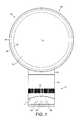
- FIG. 1is a front view of a fan assembly
- FIG. 2is a perspective view of the nozzle of the fan assembly of FIG. 1 ;
- FIG. 3is a sectional view through the fan assembly of FIG. 1 ;
- FIG. 4is an enlarged view of part of FIG. 3 ;
- FIG. 5( a )is a side view of the fan assembly of FIG. 1 showing the fan assembly in an untilted position;
- FIG. 5( b )is a side view of the fan assembly of FIG. 1 showing the fan assembly in a first tilted position
- FIG. 5( c )is a side view of the fan assembly of FIG. 1 showing the fan assembly in a second tilted position;
- FIG. 6is a top perspective view of the upper base member of the fan assembly of FIG. 1 ;
- FIG. 7is a rear perspective view of the main body of the fan assembly of FIG. 1 ;
- FIG. 8is an exploded view of the main body of FIG. 7 ;
- FIG. 9( a )illustrates the paths of two sectional views through the stand when the fan assembly is in an untilted position
- FIG. 9( b )is a sectional view along line A-A of FIG. 9( a ) ;
- FIG. 9( c )is a sectional view along line B-B of FIG. 9( a ) ;
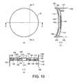
- FIG. 10( a )illustrates the paths of two further sectional views through the stand when the fan assembly is in an untilted position
- FIG. 10( b )is a sectional view along line C-C of FIG. 10( a ) ;
- FIG. 10( c )is a sectional view along line D-D of FIG. 10( a ) ;
- FIG. 1is a front view of a fan assembly 10 .
- the fan assembly 10is preferably in the form of a bladeless fan assembly comprising a stand 12 and a nozzle 14 mounted on and supported by the stand 12 .
- the stand 12comprises a substantially cylindrical outer casing 16 having a plurality of air inlets 18 in the form of apertures located in the outer casing 16 and through which a primary air flow is drawn into the stand 12 from the external environment.
- the stand 12further comprises a plurality of user-operable buttons 20 and a user-operable dial 22 for controlling the operation of the fan assembly 10 .
- the stand 12has a height in the range from 200 to 300 mm
- the outer casing 16has an external diameter in the range from 100 to 200 mm.
- the nozzle 14has an annular shape and defines a central opening 24 .
- the nozzle 14has a height in the range from 200 to 400 mm.
- the nozzle 14comprises a mouth 26 located towards the rear of the fan assembly 10 for emitting air from the fan assembly 10 and through the opening 24 .
- the mouth 26extends at least partially about the opening 24 .
- the inner periphery of the nozzle 14comprises a Coanda surface 28 located adjacent the mouth 26 and over which the mouth 26 directs the air emitted from the fan assembly 10 , a diffuser surface 30 located downstream of the Coanda surface 28 and a guide surface 32 located downstream of the diffuser surface 30 .
- the diffuser surface 30is arranged to taper away from the central axis X of the opening 24 in such a way so as to assist the flow of air emitted from the fan assembly 10 .
- the angle subtended between the diffuser surface 30 and the central axis X of the opening 24is in the range from 5 to 25°, and in this example is around 15°.
- the guide surface 32is arranged at an angle to the diffuser surface 30 to further assist the efficient delivery of a cooling air flow from the fan assembly 10 .
- the guide surface 32is preferably arranged substantially parallel to the central axis X of the opening 24 to present a substantially flat and substantially smooth face to the air flow emitted from the mouth 26 .
- a visually appealing tapered surface 34is located downstream from the guide surface 32 , terminating at a tip surface 36 lying substantially perpendicular to the central axis X of the opening 24 .
- the angle subtended between the tapered surface 34 and the central axis X of the opening 24is preferably around 45°.
- the overall depth of the nozzle 24 in a direction extending along the central axis X of the opening 24is in the range from 100 to 150 mm, and in this example is around 110 mm.
- FIG. 3illustrates a sectional view through the fan assembly 10 .
- the stand 12comprises a base formed from a lower base member 38 and an upper base member 40 mounted on the lower base member 38 , and a main body 42 mounted on the base.
- an interface Iis thus formed between the main body 42 and the base.
- the interface Ihas a curved, preferably undulating, outer periphery At least the outer surfaces of the base and the main body 42 which are adjacent to the interface thus have substantially the same, in this embodiment circular, profile.
- the lower base member 38has a substantially flat bottom surface 43 .
- the upper base member 40houses a controller 44 for controlling the operation of the fan assembly 10 in response to depression of the user operable buttons 20 shown in FIGS. 1 and 2 , and/or manipulation of the user operable dial 22 .
- the upper base member 40may also house an oscillating mechanism 46 for oscillating the upper base member 40 and the main body 42 relative to the lower base member 38 .
- the range of each oscillation cycle of the main body 42is preferably between 60° and 120°, and in this example is around 90°.
- the oscillating mechanism 46is arranged to perform around 3 to 5 oscillation cycles per minute.
- a mains power cable 48extends through an aperture formed in the lower base member 38 for supplying electrical power to the fan assembly 10 .
- the main body 42 of the stand 12has an open upper end to which the nozzle 14 is connected, for example by a snap-fit connection.
- the main body 42comprises a cylindrical grille 50 in which an array of apertures is formed to provide the air inlets 18 of the stand 12 .
- the main body 42houses an impeller 52 for drawing the primary air flow through the apertures of the grille 50 and into the stand 12 .
- the impeller 52is in the form of a mixed flow impeller.
- the impeller 52is connected to a rotary shaft 54 extending outwardly from a motor 56 .
- the motor 56is a DC brushless motor having a speed which is variable by the controller 44 in response to user manipulation of the dial 22 .
- the maximum speed of the motor 56is preferably in the range from 5,000 to 10,000 rpm.
- the motor 56is housed within a motor bucket comprising an upper portion 58 connected to a lower portion 60 .
- One of the upper portion 58 and the lower portion 60 of the motor bucketcomprises a diffuser 62 in the form of a stationary disc having spiral blades, and which is located downstream from the impeller 52 .
- the motor bucketis located within, and mounted on, an impeller housing 64 .
- the impeller housing 64is, in turn, mounted on a plurality of angularly spaced supports 66 , in this example three supports, located within the main body 42 of the stand 12 .
- a generally frustro-conical shroud 68is located within the impeller housing 64 .
- the shroud 68is shaped so that the outer edges of the impeller 52 are in close proximity to, but do not contact, the inner surface of the shroud 68 .
- a substantially annular inlet member 70is connected to the bottom of the impeller housing 64 for guiding the primary air flow into the impeller housing 64 .
- the stand 12further comprises silencing foam for reducing noise emissions from the stand 12 .
- the main body 42 of the stand 12comprises a disc-shaped foam member 72 located towards the base of the main body 42 , and a substantially annular foam member 74 located within the motor bucket.
- FIG. 4illustrates a sectional view through the nozzle 14 .
- the nozzle 14comprises an annular outer casing section 80 connected to and extending about an annular inner casing section 82 .
- Each of these sectionsmay be formed from a plurality of connected parts, but in this embodiment each of the outer casing section 80 and the inner casing section 82 is formed from a respective, single molded part.
- the inner casing section 82defines the central opening 24 of the nozzle 14 , and has an external peripheral surface 84 which is shaped to define the Coanda surface 28 , diffuser surface 30 , guide surface 32 and tapered surface 34 .
- the outer casing section 80 and the inner casing section 82together define an annular interior passage 86 of the nozzle 14 .
- the interior passage 86extends about the opening 24 .
- the interior passage 86is bounded by the internal peripheral surface 88 of the outer casing section 80 and the internal peripheral surface 90 of the inner casing section 82 .
- the outer casing section 80comprises a base 92 which is connected to, and over, the open upper end of the main body 42 of the stand 12 , for example by a snap-fit connection.
- the base 92 of the outer casing section 80comprises an aperture through which the primary air flow enters the interior passage 86 of the nozzle 14 from the open upper end of the main body 42 of the stand 12 .
- the mouth 26 of the nozzle 14is located towards the rear of the fan assembly 10 .
- the mouth 26is defined by overlapping, or facing, portions 94 , 96 of the internal peripheral surface 88 of the outer casing section 80 and the external peripheral surface 84 of the inner casing section 82 , respectively.
- the mouth 26is substantially annular and, as illustrated in FIG. 4 , has a substantially U-shaped cross-section when sectioned along a line passing diametrically through the nozzle 14 .
- the overlapping portions 94 , 96 of the internal peripheral surface 88 of the outer casing section 80 and the external peripheral surface 84 of the inner casing section 82are shaped so that the mouth 26 tapers towards an outlet 98 arranged to direct the primary flow over the Coanda surface 28 .
- the outlet 98is in the form of an annular slot, preferably having a relatively constant width in the range from 0.5 to 5 mm. In this example the outlet 98 has a width of around 1.1 mm.
- Spacersmay be spaced about the mouth 26 for urging apart the overlapping portions 94 , 96 of the internal peripheral surface 88 of the outer casing section 80 and the external peripheral surface 84 of the inner casing section 82 to maintain the width of the outlet 98 at the desired level.
- These spacersmay be integral with either the internal peripheral surface 88 of the outer casing section 80 or the external peripheral surface 84 of the inner casing section 82 .
- the main body 42is moveable relative to the base of the stand 12 between a first fully tilted position, as illustrated in FIG. 5( b ) , and a second fully tilted position, as illustrated in FIG. 5( c ) .
- This axis Xis preferably inclined by an angle of around 10° as the main body is moved from an untilted position, as illustrated in FIG. 5( a ) to one of the two fully tilted positions.
- the outer surfaces of the main body 42 and the upper base member 40are shaped so that adjoining portions of these outer surfaces of the main body 42 and the base are substantially flush when the main body 42 is in the untilted position.
- the upper base member 40comprises an annular lower surface 100 which is mounted on the lower base member 38 , a substantially cylindrical side wall 102 and a curved upper surface 104 .
- the side wall 102comprises a plurality of apertures 106 .
- the user-operable dial 22protrudes through one of the apertures 106 whereas the user-operable buttons 20 are accessible through the other apertures 106 .
- the curved upper surface 104 of the upper base member 40is concave in shape, and may be described as generally saddle-shaped.
- An aperture 108is formed in the upper surface 104 of the upper base member 40 for receiving an electrical cable 110 (shown in FIG. 3 ) extending from the motor 56 .
- the upper base member 40further comprises four support members 120 for supporting the main body 42 on the upper base member 40 .
- the support members 120project upwardly from the upper surface 104 of the upper base member 40 , and are arranged such that they are substantially equidistant from each other, and substantially equidistant from the center of the upper surface 104 .
- a first pair of the support members 120is located along the line B-B indicated in FIG. 9( a )
- a second pair of the support members 120is parallel with the first pair of support members 120 .
- each support member 120comprises a cylindrical outer wall 122 , an open upper end 124 and a closed lower end 126 .
- the outer wall 122 of the support member 120surrounds a rolling element 128 in the form of a ball bearing.
- the rolling element 128preferably has a radius which is slightly smaller than the radius of the cylindrical outer wall 122 so that the rolling element 128 is retained by and moveable within the support member 120 .
- the rolling element 128is urged away from the upper surface 104 of the upper base member 40 by a resilient element 130 located between the closed lower end 126 of the support member 120 and the rolling element 128 so that part of the rolling element 128 protrudes beyond the open upper end 124 of the support member 120 .
- the resilient member 130is in the form of a coiled spring.
- the upper base member 40also comprises a plurality of rails for retaining the main body 42 on the upper base member 40 .
- the railsalso serve to guide the movement of the main body 42 relative to the upper base member 40 so that there is substantially no twisting or rotation of the main body 42 relative to the upper base member 40 as it is moved from or to a tilted position.
- Each of the railsextends in a direction substantially parallel to the axis X.
- one of the railslies along line D-D indicated in FIG. 10( a ) .
- the plurality of railscomprises a pair of relatively long, inner rails 140 located between a pair of relatively short, outer rails 142 .
- each of the inner rails 140has a cross-section in the form of an inverted L-shape, and comprises a wall 144 which extends between a respective pair of the support members 120 , and which is connected to, and upstanding from, the upper surface 104 of the upper base member 40 .
- Each of the inner rails 140further comprises a curved flange 146 which extends along the length of the wall 144 , and which protrudes orthogonally from the top of the wall 144 towards the adjacent outer guide rail 142 .
- Each of the outer rails 142also has a cross-section in the form of an inverted L-shape, and comprises a wall 148 which is connected to, and upstanding from, the upper surface 52 of the upper base member 40 and a curved flange 150 which extends along the length of the wall 148 , and which protrudes orthogonally from the top of the wall 148 away from the adjacent inner guide rail 140 .
- the main body 42comprises a substantially cylindrical side wall 160 , an annular lower end 162 and a curved base 164 which is spaced from lower end 162 of the main body 42 to define a recess.
- the grille 50is preferably integral with the side wall 160 .
- the side wall 160 of the main body 42has substantially the same external diameter as the side wall 102 of the upper base member 40 .
- the base 164is convex in shape, and may be described generally as having an inverted saddle-shape.
- An aperture 166is formed in the base 164 for allowing the cable 110 to extend from the base 164 of the main body 42 .
- Two pairs of stop members 168extend upwardly (as illustrated in FIG.
- Each pair of stop members 168is located along a line extending in a direction substantially parallel to the axis X.
- one of the pairs of stop members 168is located along line D-D illustrated in FIG. 10( a ) .
- a convex tilt plate 170is connected to the base 164 of the main body 42 .
- the tilt plate 170is located within the recess of the main body 42 , and has a curvature which is substantially the same as that of the base 164 of the main body 42 .
- Each of the stop members 168protrudes through a respective one of a plurality of apertures 172 located about the periphery of the tilt plate 170 .
- the tilt plate 170is shaped to define a pair of convex races 174 for engaging the rolling elements 128 of the upper base member 40 .
- Each race 174extends in a direction substantially parallel to the axis X, and is arranged to receive the rolling elements 128 of a respective pair of the support members 120 , as illustrated in FIG. 9( c ) .
- the tilt plate 170also comprises a plurality of runners, each of which is arranged to be located at least partially beneath a respective rail of the upper base member 40 and thus co-operate with that rail to retain the main body 42 on the upper base member 40 and to guide the movement of the main body 42 relative to the upper base member 40 .
- each of the runnersextends in a direction substantially parallel to the axis X.
- one of the runnerslies along line D-D indicated in FIG. 10( a ) .
- the plurality of runnerscomprises a pair of relatively long, inner runners 180 located between a pair of relatively short, outer runners 182 .
- each of the inner runners 180has a cross-section in the form of an inverted L-shape, and comprises a substantially vertical wall 184 and a curved flange 186 which protrudes orthogonally and inwardly from part of the top of the wall 184 .
- the curvature of the curved flange 186 of each inner runner 180is substantially the same as the curvature of the curved flange 146 of each inner rail 140 .
- Each of the outer runners 182also has a cross-section in the form of an inverted L-shape, and comprises a substantially vertical wall 188 and a curved flange 190 which extends along the length of the wall 188 , and which protrudes orthogonally and inwardly from the top of the wall 188 .
- the curvature of the curved flange 190 of each outer runner 182is substantially the same as the curvature of the curved flange 150 of each outer rail 142 .
- the tilt plate 170further comprises an aperture 192 for receiving the cable 110 .
- the tilt plate 170is inverted from the orientation illustrated in FIGS. 7 and 8 , and the races 174 of the tilt plate located directly behind and in line with the support members 120 of the upper base member 40 .
- the cable 110 extending through the aperture 166 of the main body 42may be threaded through the apertures 108 , 192 in the tilt plate 170 and the upper base member 40 respectively for subsequent connection to the controller 44 , as illustrated in FIG. 3 .
- the tilt plate 170is then slid over the upper base member 40 so that the rolling elements 128 engage the races 174 , as illustrated in FIGS.
- the curved flange 190 of each outer runner 182is located beneath the curved flange 150 of a respective outer rail 142 , as illustrated in FIGS. 9( b ) and 10( b )
- the curved flange 186 of each inner runner 180is located beneath the curved flange 146 of a respective inner rail 140 , as illustrated in FIGS. 9( b ), 10( b ) and 10( c ) .
- the main body 42With the tilt plate 170 positioned centrally on the upper base member 40 , the main body 42 is lowered on to the tilt plate 170 so that the stop members 168 are located within the apertures 172 of the tilt plate 170 , and the tilt plate 170 is housed within the recess of the main body 42 .
- the upper base member 40 and the main body 42are then inverted, and the base member 40 displaced along the direction of the axis X to reveal a first plurality of apertures 194 a located on the tilt plate 170 .
- Each of these apertures 194 ais aligned with a tubular protrusion 196 a on the base 164 of the main body 42 .
- a self-tapping screwis screwed into each of the apertures 194 a to enter the underlying protrusion 196 a , thereby partially connecting the tilt plate 170 to the main body 42 .
- the upper base member 40is then displaced in the reverse direction to reveal a second plurality of apertures 194 b located on the tilt plate 170 .
- Each of these apertures 194 bis also aligned with a tubular protrusion 196 b on the base 164 of the main body 42 .
- a self-tapping screwis screwed into each of the apertures 194 b to enter the underlying protrusion 196 b to complete the connection of the tilt plate 170 to the main body 42 .
- the main body 42When the main body 42 is attached to the base and the bottom surface 43 of the lower base member 38 positioned on a support surface, the main body 42 is supported by the rolling elements 128 of the support members 120 .
- the resilient elements 130 of the support members 120urge the rolling elements 128 away from the closed lower ends 126 of the support members 120 by a distance which is sufficient to inhibit scraping of the upper surfaces of the upper base member 40 when the main body 42 is tilted.
- the lower end 162 of the main body 42is urged away from the upper surface 104 of the upper base member 40 to prevent contact therebetween when the main body 42 is tilted.
- the action of the resilient elements 130urges the concave upper surfaces of the curved flanges 186 , 190 of the runners against the convex lower surfaces of the curved flanges 146 , 150 of the rails.
- the userslides the main body 42 in a direction parallel to the axis X to move the main body 42 towards one of the fully tilted positions illustrated in FIGS. 5( b ) and 5( c ) , causing the rolling elements 128 move along the races 174 .
- the userreleases the main body 42 , which is retained in the desired position by frictional forces generated through the contact between the concave upper surfaces of the curved flanges 186 , 190 of the runners and the convex lower surfaces of the curved flanges 146 , 150 of the rails acting to resist the movement under gravity of the main body 42 towards the untilted position illustrated in FIG. 5( a ) .
- the fully titled positions of the main body 42are defined by the abutment of one of each pair of stop members 168 with a respective inner rail 140 .
- the userdepresses an appropriate one of the buttons 20 on the stand 12 , in response to which the controller 44 activates the motor 56 to rotate the impeller 52 .
- the rotation of the impeller 52causes a primary air flow to be drawn into the stand 12 through the air inlets 18 .
- the primary air flowmay be between 20 and 30 liters per second.
- the primary air flowpasses sequentially through the impeller housing 64 and the open upper end of the main body 42 to enter the interior passage 86 of the nozzle 14 .
- the primary air flowis divided into two air streams which pass in opposite directions around the central opening 24 of the nozzle 14 .
- the air streamspass through the interior passage 86 , air enters the mouth 26 of the nozzle 14 .
- the air flow into the mouth 26is preferably substantially even about the opening 24 of the nozzle 14 .
- the flow direction of the portion of the air streamis substantially reversed.
- the portion of the air streamis constricted by the tapering section of the mouth 26 and emitted through the outlet 98 .
- the primary air flow emitted from the mouth 26is directed over the Coanda surface 28 of the nozzle 14 , causing a secondary air flow to be generated by the entrainment of air from the external environment, specifically from the region around the outlet 98 of the mouth 26 and from around the rear of the nozzle 14 .
- This secondary air flowpasses through the central opening 24 of the nozzle 14 , where it combines with the primary air flow to produce a total air flow, or air current, projected forward from the nozzle 14 .
- the mass flow rate of the air current projected forward from the fan assembly 10may be up to 400 liters per second, preferably up to 600 liters per second, and the maximum speed of the air current may be in the range from 2.5 to 4 m/s.
- the even distribution of the primary air flow along the mouth 26 of the nozzle 14ensures that the air flow passes evenly over the diffuser surface 30 .
- the diffuser surface 30causes the mean speed of the air flow to be reduced by moving the air flow through a region of controlled expansion.
- the relatively shallow angle of the diffuser surface 30 to the central axis X of the opening 24allows the expansion of the air flow to occur gradually.
- a harsh or rapid divergencewould otherwise cause the air flow to become disrupted, generating vortices in the expansion region.
- Such vorticescan lead to an increase in turbulence and associated noise in the air flow which can be undesirable, particularly in a domestic product such as a fan.
- the air flow projected forwards beyond the diffuser surface 30can tend to continue to diverge.
- the presence of the guide surface 32 extending substantially parallel to the central axis X of the opening 30further converges the air flow. As a result, the air flow can travel efficiently out from the nozzle 14 , enabling the air flow can be experienced rapidly at a distance of several meters from the fan assembly 10 .
- the stand 12may be used in a variety of appliances other than a fan assembly.
- the movement of the main body 42 relative to the basemay be motorized, and actuated by user through depression of one of the buttons 20 .
Landscapes
- Engineering & Computer Science (AREA)
- Mechanical Engineering (AREA)
- General Engineering & Computer Science (AREA)
- Chemical & Material Sciences (AREA)
- Combustion & Propulsion (AREA)
- Physics & Mathematics (AREA)
- Fluid Mechanics (AREA)
- Structures Of Non-Positive Displacement Pumps (AREA)
- Jet Pumps And Other Pumps (AREA)
Abstract
Description
This application is a continuation of U.S. application Ser. No. 12/716,749, filed Mar. 3, 2010, which claims the priority of United Kingdom Application No. 0903679.9, filed Mar. 4, 2009, the entire contents of which are incorporated herein by reference.
The present invention relates to a fan assembly. Particularly, but not exclusively, the present invention relates to a domestic fan, such as a desk fan, for creating air circulation and air current in a room, in an office or other domestic environment.
A conventional domestic fan typically includes a set of blades or vanes mounted for rotation about an axis, and drive apparatus for rotating the set of blades to generate an air flow. The movement and circulation of the air flow creates a ‘wind chill’ or breeze and, as a result, the user experiences a cooling effect as heat is dissipated through convection and evaporation.
Such fans are available in a variety of sizes and shapes. For example, a ceiling fan can be at least 1 m in diameter, and is usually mounted in a suspended manner from the ceiling to provide a downward flow of air to cool a room. On the other hand, desk fans are often around 30 cm in diameter, and are usually free standing and portable. Other types of fan can be attached to the floor or mounted on a wall. Fans such as that disclosed in U.S. D 103,476 and U.S. Pat. No. 1,767,060 are suitable for standing on a desk or a table.
A disadvantage of this type of fan is that the air flow produced by the rotating blades is generally not uniform. This is due to variations across the blade surface or across the outward facing surface of the fan. The extent of these variations can vary from product to product and even from one individual fan machine to another. These variations result in the generation of an uneven or ‘choppy’ air flow which can be felt as a series of pulses of air and which can be uncomfortable for a user. A further disadvantage is that the cooling effect created by the fan diminishes with distance from the user. This means that the fan must be placed in close proximity to the user in order for the user to experience the cooling effect of the fan.
An oscillating mechanism may be employed to rotate the outlet from the fan so that the air flow is swept over a wide area of a room. The oscillating mechanism can lead to some improvement in the quality and uniformity of the air flow felt by a user although the characteristic ‘choppy’ air flow remains.
Locating fans such as those described above close to a user is not always possible as the bulky shape and structure of the fan mean that the fan occupies a significant amount of the user's work space area.
Some fans, such as that described in U.S. Pat. No. 5,609,473, provide a user with an option to adjust the direction in which air is emitted from the fan. In U.S. Pat. No. 5,609,473, the fan comprises a base and a pair of yokes each upstanding from a respective end of the base. The outer body of the fan houses a motor and a set of rotating blades. The outer body is secured to the yokes so as to be pivotable relative to the base. The fan body may be swung relative to the base from a generally vertical, untilted position to an inclined, tilted position. In this way the direction of the air flow emitted from the fan can be altered.
In such fans, a securing mechanism may be employed to fix the position of the body of the fan relative to the base. The securing mechanism may comprise a clamp or manual locking screws which may be difficult to use, particularly for the elderly or for users with impaired dexterity.
In a domestic environment it is desirable for appliances to be as small and compact as possible due to space restrictions. In contrast, fan adjustment mechanisms are often bulky, and are mounted to, and often extend from, the outer surface of the fan assembly. When such a fan is placed on a desk, the footprint of the adjustment mechanism can undesirably reduce the area available for paperwork, a computer or other office equipment. In addition, it is undesirable for parts of the appliance to project outwardly, both for safety reasons and because such parts can be difficult to clean.
In a first aspect, the present invention provides a fan assembly for creating an air current, the fan assembly comprising an air outlet mounted on a stand comprising a base and a body tiltable relative to the base from an untilted position to a tilted position, each of the base and the body having an outer surface shaped so that adjoining portions of the outer surfaces are substantially flush when the body is in the untilted position.
This can provide the stand with a tidy and uniform appearance when in an untilted position. This type of uncluttered appearance is desirable and often appeals to a user or customer. The flush portions also have the benefit of allowing the outer surfaces of the base and the body to be quickly and easily wiped clean.
The body is preferably slidable relative to the base between the untilted position and the tilted position. This can enable the body to be easily moved relative to the base, for example by either pushing or pulling the body relative to the base, between the tilted and untilted positions.
Preferably, the stand comprises an interface between the base and the body, and at least the outer surfaces of the base and the body which are adjacent to the interface have substantially the same profile. The interface preferably has a curved, more preferably undulating, outer periphery. Facing surfaces of the base and the main body are preferably conformingly curved. The base preferably has a curved upper surface, whereas the body preferably has a conformingly curved upper surface. For example the upper surface of the base may be convex, whereas the lower surface of the body may be concave.
In a preferred embodiment the outer surfaces of the base and the body have substantially the same profile. For example, the profile of the outer surfaces of the base and the body may be substantially circular, elliptical, or polyhedral.
The stand preferably comprises interlocking members for retaining the body on the base. The interlocking members are preferably enclosed by the outer surfaces of the base and the body when the body is in the untilted position so that the stand retains its tidy and uniform appearance. Therefore, in a second aspect the present invention provides a fan assembly for creating an air current, the fan assembly comprising an air outlet mounted on a stand comprising a base and a body tiltable relative to the base from an untilted position to a tilted position, and interlocking members for retaining the body on the base, wherein the interlocking members are enclosed by the outer surfaces of the base and the body when the body is in the untilted position.
The stand preferably comprises a mechanism for urging the interlocking members together to resist movement of the body from the tilted position. The base preferably comprises a plurality of support members for supporting the body, and which are preferably also enclosed by the outer surfaces of the base and the body when the body is in the untilted position. Each support member preferably comprises a rolling element for supporting the body, the body comprising a plurality of curved races for receiving the rolling elements and within which the rolling elements move as the body is moved from an untilted position to a tilted position.
The interlocking members preferably comprise a first plurality of locking members located on the base, and a second plurality of locking members located on the body and which are retained by the first plurality of locking members. Each of the locking members is preferably substantially L-shaped. The interlocking members preferably comprise interlocking flanges, which are preferably curved. The curvature of the flanges of the interlocking members of the base is preferably substantially the same as the curvature of the flanges of the interlocking members of the body. This can maximize the frictional forces generated between the interlocking flanges which act against the movement of the body from the tilted position.
In the preferred embodiment the center of gravity of the fan assembly does not fall outside the footprint of the base when the body is in a fully tilted position, thereby reducing the risk of the fan assembly toppling over in use. The stand preferably comprises a mechanism for inhibiting the movement of the body relative to the base beyond a fully tilted position. The movement inhibiting mechanism preferably comprises a stop member depending from the body for engaging part of the base when the body is in a fully tilted position. In the preferred embodiment the stop member is arranged to engage part of the interlocking members, preferably a flange of an interlocking member of the base, to inhibit movement of the body relative to the base beyond the fully tilted position.
The fan assembly is preferably in the form of a bladeless fan assembly. Through use of a bladeless fan assembly an air current can be generated without the use of a bladed fan. Without the use of a bladed fan to project the air current from the fan assembly, a relatively uniform air current can be generated and guided into a room or towards a user. The air current can travel efficiently out from the outlet, losing little energy and velocity to turbulence.
The term ‘bladeless’ is used to describe a fan assembly in which air flow is emitted or projected forward from the fan assembly without the use of moving blades. Consequently, a bladeless fan assembly can be considered to have an output area, or emission zone, absent moving blades from which the air flow is directed towards a user or into a room. The output area of the bladeless fan assembly may be supplied with a primary air flow generated by one of a variety of different sources, such as pumps, generators, motors or other fluid transfer devices, and which may include a rotating device such as a motor rotor and/or a bladed impeller for generating the air flow. The generated primary air flow can pass from the room space or other environment outside the fan assembly into the fan assembly, and then back out to the room space through the outlet.
Hence, the description of a fan assembly as bladeless is not intended to extend to the description of the power source and components such as motors that are required for secondary fan functions. Examples of secondary fan functions can include lighting, adjustment and oscillation of the fan assembly.
The stand preferably comprises a device for creating an air flow through the fan assembly. Preferably the device for creating an air flow through the fan assembly comprises an impeller, a motor for rotating the impeller, and preferably also a diffuser located downstream from the impeller. The impeller is preferably a mixed flow impeller. The motor is preferably a DC brushless motor to avoid frictional losses and carbon debris from the brushes used in a traditional brushed motor. Reducing carbon debris and emissions is advantageous in a clean or pollutant sensitive environment such as a hospital or around those with allergies. While induction motors, which are generally used in pedestal fans, also have no brushes, a DC brushless motor can provide a much wider range of operating speeds than an induction motor.
The device for creating an air flow through the fan assembly is preferably located within the body of the stand. The weight of the components of the device for creating an air flow, in particular the motor, can act to stabilize the body on the base when the body is in a tilted position. The body preferably comprises at least one air inlet through which air is drawn into the fan assembly by the mechanism for creating an air flow. This can provide a short, compact air flow path that minimizes noise and frictional losses.
The base preferably comprises a controller for controlling the fan assembly. For safety reasons and ease of use, it can be advantageous to locate control elements away from the tiltable body so that the control functions, such as, for example, oscillation, lighting or activation of a speed setting, are not activated during a tilt operation.
The air outlet preferably comprises a nozzle mounted on the stand, the nozzle comprising a mouth for emitting the air flow, the nozzle extending about an opening through which air from outside the nozzle is drawn by the air flow emitted from the mouth. Preferably, the nozzle surrounds the opening. The nozzle may be an annular nozzle which preferably has a height in the range from 200 to 600 mm, more preferably in the range from 250 to 500 mm.
Preferably, the mouth of the nozzle extends about the opening, and is preferably annular. The nozzle preferably comprises an inner casing section and an outer casing section which define the mouth of the nozzle. Each section is preferably formed from a respective annular member, but each section may be provided by a plurality of members connected together or otherwise assembled to form that section. The outer casing section is preferably shaped so as to partially overlap the inner casing section. This can enable an outlet of the mouth to be defined between overlapping portions of the external surface of the inner casing section and the internal surface of the outer casing section of the nozzle. The outlet is preferably in the form of a slot, preferably having a width in the range from 0.5 to 5 mm, more preferably in the range from 0.5 to 1.5 mm. The nozzle may comprise a plurality of spacers for urging apart the overlapping portions of the inner casing section and the outer casing section of the nozzle. This can assist in maintaining a substantially uniform outlet width about the opening. The spacers are preferably evenly spaced along the outlet.
The nozzle preferably comprises an interior passage for receiving the air flow from the stand. The interior passage is preferably annular, and is preferably shaped to divide the air flow into two air streams which flow in opposite directions around the opening. The interior passage is preferably also defined by the inner casing section and the outer casing section of the nozzle.
The fan assembly preferably comprises a mechanism for oscillating the nozzle so that the air current is swept over an arc, preferably in the range from 60 to 120°. For example, the base of the stand may comprise a mechanism for oscillating an upper base member, to which the body is connected, relative to a lower base member.
The maximum air flow of the air current generated by the fan assembly is preferably in the range from 300 to 800 liters per second, more preferably in the range from 500 to 800 liters per second.
The nozzle may comprise a Coanda surface located adjacent the mouth and over which the mouth is arranged to direct the air flow emitted therefrom. Preferably, the external surface of the inner casing section of the nozzle is shaped to define the Coanda surface. The Coanda surface preferably extends about the opening. A Coanda surface is a known type of surface over which fluid flow exiting an output orifice close to the surface exhibits the Coanda effect. The fluid tends to flow over the surface closely, almost ‘clinging to’ or ‘hugging’ the surface. The Coanda effect is already a proven, well documented method of entrainment in which a primary air flow is directed over a Coanda surface. A description of the features of a Coanda surface, and the effect of fluid flow over a Coanda surface, can be found in articles such as Reba, Scientific American, Volume 214, June 1966pages 84 to 92. Through use of a Coanda surface, an increased amount of air from outside the fan assembly is drawn through the opening by the air emitted from the mouth.
Preferably, an air flow enters the nozzle of the fan assembly from the stand. In the following description this air flow will be referred to as primary air flow. The primary air flow is emitted from the mouth of the nozzle and preferably passes over a Coanda surface. The primary air flow entrains air surrounding the mouth of the nozzle, which acts as an air amplifier to supply both the primary air flow and the entrained air to the user. The entrained air will be referred to here as a secondary air flow. The secondary air flow is drawn from the room space, region or external environment surrounding the mouth of the nozzle and, by displacement, from other regions around the fan assembly, and passes predominantly through the opening defined by the nozzle. The primary air flow directed over the Coanda surface combined with the entrained secondary air flow equates to a total air flow emitted or projected forward from the opening defined by the nozzle. Preferably, the entrainment of air surrounding the mouth of the nozzle is such that the primary air flow is amplified by at least five times, more preferably by at least ten times, while a smooth overall output is maintained.
Preferably, the nozzle comprises a diffuser surface located downstream of the Coanda surface. The external surface of the inner casing section of the nozzle is preferably shaped to define the diffuser surface.
In a third aspect, the present invention provides a stand for a fan assembly, the stand comprising a base and a body tiltable relative to the base, the base and the body each having an outer surface shaped so that adjoining portions of the outer surfaces are substantially flush when the body is in the untilted position. In a fourth aspect the present invention provides a stand comprising a base and a body tiltable relative to the base from an untilted position to a tilted position, and interlocking members for retaining the body on the base, wherein the interlocking members are enclosed by the outer surfaces of the base and the body when the body is in the untilted position.
Features described above in relation to the first and second aspects of the invention are equally applicable to each of the third and fourth aspects of the invention, and vice versa.
An embodiment of the invention will now be described with reference to the accompanying drawings, in which:
With reference also toFIG. 2 , thenozzle 14 has an annular shape and defines acentral opening 24. Thenozzle 14 has a height in the range from 200 to 400 mm. Thenozzle 14 comprises amouth 26 located towards the rear of thefan assembly 10 for emitting air from thefan assembly 10 and through theopening 24. Themouth 26 extends at least partially about theopening 24. The inner periphery of thenozzle 14 comprises aCoanda surface 28 located adjacent themouth 26 and over which themouth 26 directs the air emitted from thefan assembly 10, adiffuser surface 30 located downstream of theCoanda surface 28 and aguide surface 32 located downstream of thediffuser surface 30. Thediffuser surface 30 is arranged to taper away from the central axis X of theopening 24 in such a way so as to assist the flow of air emitted from thefan assembly 10. The angle subtended between thediffuser surface 30 and the central axis X of theopening 24 is in the range from 5 to 25°, and in this example is around 15°. Theguide surface 32 is arranged at an angle to thediffuser surface 30 to further assist the efficient delivery of a cooling air flow from thefan assembly 10. Theguide surface 32 is preferably arranged substantially parallel to the central axis X of theopening 24 to present a substantially flat and substantially smooth face to the air flow emitted from themouth 26. A visually appealing taperedsurface 34 is located downstream from theguide surface 32, terminating at atip surface 36 lying substantially perpendicular to the central axis X of theopening 24. The angle subtended between thetapered surface 34 and the central axis X of theopening 24 is preferably around 45°. The overall depth of thenozzle 24 in a direction extending along the central axis X of theopening 24 is in the range from 100 to 150 mm, and in this example is around 110 mm.
Thelower base member 38 has a substantiallyflat bottom surface 43. Theupper base member 40 houses acontroller 44 for controlling the operation of thefan assembly 10 in response to depression of the useroperable buttons 20 shown inFIGS. 1 and 2 , and/or manipulation of the useroperable dial 22. Theupper base member 40 may also house anoscillating mechanism 46 for oscillating theupper base member 40 and themain body 42 relative to thelower base member 38. The range of each oscillation cycle of themain body 42 is preferably between 60° and 120°, and in this example is around 90°. In this example, theoscillating mechanism 46 is arranged to perform around 3 to 5 oscillation cycles per minute. Amains power cable 48 extends through an aperture formed in thelower base member 38 for supplying electrical power to thefan assembly 10.
Themain body 42 of thestand 12 has an open upper end to which thenozzle 14 is connected, for example by a snap-fit connection. Themain body 42 comprises acylindrical grille 50 in which an array of apertures is formed to provide theair inlets 18 of thestand 12. Themain body 42 houses animpeller 52 for drawing the primary air flow through the apertures of thegrille 50 and into thestand 12. Preferably, theimpeller 52 is in the form of a mixed flow impeller. Theimpeller 52 is connected to arotary shaft 54 extending outwardly from amotor 56. In this example, themotor 56 is a DC brushless motor having a speed which is variable by thecontroller 44 in response to user manipulation of thedial 22. The maximum speed of themotor 56 is preferably in the range from 5,000 to 10,000 rpm. Themotor 56 is housed within a motor bucket comprising anupper portion 58 connected to alower portion 60. One of theupper portion 58 and thelower portion 60 of the motor bucket comprises adiffuser 62 in the form of a stationary disc having spiral blades, and which is located downstream from theimpeller 52.
The motor bucket is located within, and mounted on, animpeller housing 64. Theimpeller housing 64 is, in turn, mounted on a plurality of angularly spaced supports66, in this example three supports, located within themain body 42 of thestand 12. A generally frustro-conical shroud 68 is located within theimpeller housing 64. Theshroud 68 is shaped so that the outer edges of theimpeller 52 are in close proximity to, but do not contact, the inner surface of theshroud 68. A substantiallyannular inlet member 70 is connected to the bottom of theimpeller housing 64 for guiding the primary air flow into theimpeller housing 64. Preferably, thestand 12 further comprises silencing foam for reducing noise emissions from thestand 12. In this example, themain body 42 of thestand 12 comprises a disc-shapedfoam member 72 located towards the base of themain body 42, and a substantiallyannular foam member 74 located within the motor bucket.
Theouter casing section 80 and theinner casing section 82 together define an annularinterior passage 86 of thenozzle 14. Thus, theinterior passage 86 extends about theopening 24. Theinterior passage 86 is bounded by the internalperipheral surface 88 of theouter casing section 80 and the internalperipheral surface 90 of theinner casing section 82. Theouter casing section 80 comprises a base92 which is connected to, and over, the open upper end of themain body 42 of thestand 12, for example by a snap-fit connection. Thebase 92 of theouter casing section 80 comprises an aperture through which the primary air flow enters theinterior passage 86 of thenozzle 14 from the open upper end of themain body 42 of thestand 12.
Themouth 26 of thenozzle 14 is located towards the rear of thefan assembly 10. Themouth 26 is defined by overlapping, or facing,portions peripheral surface 88 of theouter casing section 80 and the externalperipheral surface 84 of theinner casing section 82, respectively. In this example, themouth 26 is substantially annular and, as illustrated inFIG. 4 , has a substantially U-shaped cross-section when sectioned along a line passing diametrically through thenozzle 14. In this example, the overlappingportions peripheral surface 88 of theouter casing section 80 and the externalperipheral surface 84 of theinner casing section 82 are shaped so that themouth 26 tapers towards anoutlet 98 arranged to direct the primary flow over theCoanda surface 28. Theoutlet 98 is in the form of an annular slot, preferably having a relatively constant width in the range from 0.5 to 5 mm. In this example theoutlet 98 has a width of around 1.1 mm. Spacers may be spaced about themouth 26 for urging apart the overlappingportions peripheral surface 88 of theouter casing section 80 and the externalperipheral surface 84 of theinner casing section 82 to maintain the width of theoutlet 98 at the desired level. These spacers may be integral with either the internalperipheral surface 88 of theouter casing section 80 or the externalperipheral surface 84 of theinner casing section 82.
Turning now toFIGS. 5(a), 5(b) and 5(c) , themain body 42 is moveable relative to the base of thestand 12 between a first fully tilted position, as illustrated inFIG. 5(b) , and a second fully tilted position, as illustrated inFIG. 5(c) . This axis X is preferably inclined by an angle of around 10° as the main body is moved from an untilted position, as illustrated inFIG. 5(a) to one of the two fully tilted positions. The outer surfaces of themain body 42 and theupper base member 40 are shaped so that adjoining portions of these outer surfaces of themain body 42 and the base are substantially flush when themain body 42 is in the untilted position.
With reference toFIG. 6 , theupper base member 40 comprises an annularlower surface 100 which is mounted on thelower base member 38, a substantiallycylindrical side wall 102 and a curvedupper surface 104. Theside wall 102 comprises a plurality ofapertures 106. The user-operable dial 22 protrudes through one of theapertures 106 whereas the user-operable buttons 20 are accessible through theother apertures 106. The curvedupper surface 104 of theupper base member 40 is concave in shape, and may be described as generally saddle-shaped. Anaperture 108 is formed in theupper surface 104 of theupper base member 40 for receiving an electrical cable110 (shown inFIG. 3 ) extending from themotor 56.
Theupper base member 40 further comprises foursupport members 120 for supporting themain body 42 on theupper base member 40. Thesupport members 120 project upwardly from theupper surface 104 of theupper base member 40, and are arranged such that they are substantially equidistant from each other, and substantially equidistant from the center of theupper surface 104. A first pair of thesupport members 120 is located along the line B-B indicated inFIG. 9(a) , and a second pair of thesupport members 120 is parallel with the first pair ofsupport members 120. With reference also toFIGS. 9(b) and 9(c) , eachsupport member 120 comprises a cylindricalouter wall 122, an openupper end 124 and a closedlower end 126. Theouter wall 122 of thesupport member 120 surrounds a rollingelement 128 in the form of a ball bearing. The rollingelement 128 preferably has a radius which is slightly smaller than the radius of the cylindricalouter wall 122 so that the rollingelement 128 is retained by and moveable within thesupport member 120. The rollingelement 128 is urged away from theupper surface 104 of theupper base member 40 by aresilient element 130 located between the closedlower end 126 of thesupport member 120 and the rollingelement 128 so that part of the rollingelement 128 protrudes beyond the openupper end 124 of thesupport member 120. In this embodiment, theresilient member 130 is in the form of a coiled spring.
Returning toFIG. 6 , theupper base member 40 also comprises a plurality of rails for retaining themain body 42 on theupper base member 40. The rails also serve to guide the movement of themain body 42 relative to theupper base member 40 so that there is substantially no twisting or rotation of themain body 42 relative to theupper base member 40 as it is moved from or to a tilted position. Each of the rails extends in a direction substantially parallel to the axis X. For example, one of the rails lies along line D-D indicated inFIG. 10(a) . In this embodiment, the plurality of rails comprises a pair of relatively long,inner rails 140 located between a pair of relatively short,outer rails 142. With reference also toFIGS. 9(b) and 10(b) , each of theinner rails 140 has a cross-section in the form of an inverted L-shape, and comprises awall 144 which extends between a respective pair of thesupport members 120, and which is connected to, and upstanding from, theupper surface 104 of theupper base member 40. Each of theinner rails 140 further comprises acurved flange 146 which extends along the length of thewall 144, and which protrudes orthogonally from the top of thewall 144 towards the adjacentouter guide rail 142. Each of theouter rails 142 also has a cross-section in the form of an inverted L-shape, and comprises awall 148 which is connected to, and upstanding from, theupper surface 52 of theupper base member 40 and acurved flange 150 which extends along the length of thewall 148, and which protrudes orthogonally from the top of thewall 148 away from the adjacentinner guide rail 140.
With reference now toFIGS. 7 and 8 , themain body 42 comprises a substantiallycylindrical side wall 160, an annularlower end 162 and acurved base 164 which is spaced fromlower end 162 of themain body 42 to define a recess. Thegrille 50 is preferably integral with theside wall 160. Theside wall 160 of themain body 42 has substantially the same external diameter as theside wall 102 of theupper base member 40. Thebase 164 is convex in shape, and may be described generally as having an inverted saddle-shape. Anaperture 166 is formed in thebase 164 for allowing thecable 110 to extend from thebase 164 of themain body 42. Two pairs ofstop members 168 extend upwardly (as illustrated inFIG. 8 ) from the periphery ofbase 164. Each pair ofstop members 168 is located along a line extending in a direction substantially parallel to the axis X. For example, one of the pairs ofstop members 168 is located along line D-D illustrated inFIG. 10(a) .
Aconvex tilt plate 170 is connected to thebase 164 of themain body 42. Thetilt plate 170 is located within the recess of themain body 42, and has a curvature which is substantially the same as that of thebase 164 of themain body 42. Each of thestop members 168 protrudes through a respective one of a plurality ofapertures 172 located about the periphery of thetilt plate 170. Thetilt plate 170 is shaped to define a pair ofconvex races 174 for engaging the rollingelements 128 of theupper base member 40. Eachrace 174 extends in a direction substantially parallel to the axis X, and is arranged to receive the rollingelements 128 of a respective pair of thesupport members 120, as illustrated inFIG. 9(c) .
Thetilt plate 170 also comprises a plurality of runners, each of which is arranged to be located at least partially beneath a respective rail of theupper base member 40 and thus co-operate with that rail to retain themain body 42 on theupper base member 40 and to guide the movement of themain body 42 relative to theupper base member 40. Thus, each of the runners extends in a direction substantially parallel to the axis X. For example, one of the runners lies along line D-D indicated inFIG. 10(a) . In this embodiment, the plurality of runners comprises a pair of relatively long,inner runners 180 located between a pair of relatively short,outer runners 182. With reference also toFIGS. 9(b) and 10(b) , each of theinner runners 180 has a cross-section in the form of an inverted L-shape, and comprises a substantiallyvertical wall 184 and acurved flange 186 which protrudes orthogonally and inwardly from part of the top of thewall 184. The curvature of thecurved flange 186 of eachinner runner 180 is substantially the same as the curvature of thecurved flange 146 of eachinner rail 140. Each of theouter runners 182 also has a cross-section in the form of an inverted L-shape, and comprises a substantiallyvertical wall 188 and acurved flange 190 which extends along the length of thewall 188, and which protrudes orthogonally and inwardly from the top of thewall 188. Again, the curvature of thecurved flange 190 of eachouter runner 182 is substantially the same as the curvature of thecurved flange 150 of eachouter rail 142. Thetilt plate 170 further comprises anaperture 192 for receiving thecable 110.
To connect themain body 42 to theupper base member 40, thetilt plate 170 is inverted from the orientation illustrated inFIGS. 7 and 8 , and theraces 174 of the tilt plate located directly behind and in line with thesupport members 120 of theupper base member 40. Thecable 110 extending through theaperture 166 of themain body 42 may be threaded through theapertures tilt plate 170 and theupper base member 40 respectively for subsequent connection to thecontroller 44, as illustrated inFIG. 3 . Thetilt plate 170 is then slid over theupper base member 40 so that the rollingelements 128 engage theraces 174, as illustrated inFIGS. 9(b) and 9(c) , thecurved flange 190 of eachouter runner 182 is located beneath thecurved flange 150 of a respectiveouter rail 142, as illustrated inFIGS. 9(b) and 10(b) , and thecurved flange 186 of eachinner runner 180 is located beneath thecurved flange 146 of a respectiveinner rail 140, as illustrated inFIGS. 9(b), 10(b) and 10(c) .
With thetilt plate 170 positioned centrally on theupper base member 40, themain body 42 is lowered on to thetilt plate 170 so that thestop members 168 are located within theapertures 172 of thetilt plate 170, and thetilt plate 170 is housed within the recess of themain body 42. Theupper base member 40 and themain body 42 are then inverted, and thebase member 40 displaced along the direction of the axis X to reveal a first plurality ofapertures 194alocated on thetilt plate 170. Each of theseapertures 194ais aligned with atubular protrusion 196aon thebase 164 of themain body 42. A self-tapping screw is screwed into each of theapertures 194ato enter theunderlying protrusion 196a, thereby partially connecting thetilt plate 170 to themain body 42. Theupper base member 40 is then displaced in the reverse direction to reveal a second plurality ofapertures 194blocated on thetilt plate 170. Each of theseapertures 194bis also aligned with atubular protrusion 196bon thebase 164 of themain body 42. A self-tapping screw is screwed into each of theapertures 194bto enter theunderlying protrusion 196bto complete the connection of thetilt plate 170 to themain body 42.
When themain body 42 is attached to the base and thebottom surface 43 of thelower base member 38 positioned on a support surface, themain body 42 is supported by the rollingelements 128 of thesupport members 120. Theresilient elements 130 of thesupport members 120 urge the rollingelements 128 away from the closed lower ends126 of thesupport members 120 by a distance which is sufficient to inhibit scraping of the upper surfaces of theupper base member 40 when themain body 42 is tilted. For example, as illustrated in each ofFIGS. 9(b), 9(c), 10(b) and 10(c) thelower end 162 of themain body 42 is urged away from theupper surface 104 of theupper base member 40 to prevent contact therebetween when themain body 42 is tilted. Furthermore, the action of theresilient elements 130 urges the concave upper surfaces of thecurved flanges curved flanges
To tilt themain body 42 relative to the base, the user slides themain body 42 in a direction parallel to the axis X to move themain body 42 towards one of the fully tilted positions illustrated inFIGS. 5(b) and 5(c) , causing the rollingelements 128 move along theraces 174. Once themain body 42 is in the desired position, the user releases themain body 42, which is retained in the desired position by frictional forces generated through the contact between the concave upper surfaces of thecurved flanges curved flanges main body 42 towards the untilted position illustrated inFIG. 5(a) . The fully titled positions of themain body 42 are defined by the abutment of one of each pair ofstop members 168 with a respectiveinner rail 140.
To operate thefan assembly 10 the user depresses an appropriate one of thebuttons 20 on thestand 12, in response to which thecontroller 44 activates themotor 56 to rotate theimpeller 52. The rotation of theimpeller 52 causes a primary air flow to be drawn into thestand 12 through theair inlets 18. Depending on the speed of themotor 56, the primary air flow may be between 20 and 30 liters per second. The primary air flow passes sequentially through theimpeller housing 64 and the open upper end of themain body 42 to enter theinterior passage 86 of thenozzle 14. Within thenozzle 14, the primary air flow is divided into two air streams which pass in opposite directions around thecentral opening 24 of thenozzle 14. As the air streams pass through theinterior passage 86, air enters themouth 26 of thenozzle 14. The air flow into themouth 26 is preferably substantially even about theopening 24 of thenozzle 14. Within each section of themouth 26, the flow direction of the portion of the air stream is substantially reversed. The portion of the air stream is constricted by the tapering section of themouth 26 and emitted through theoutlet 98.
The primary air flow emitted from themouth 26 is directed over theCoanda surface 28 of thenozzle 14, causing a secondary air flow to be generated by the entrainment of air from the external environment, specifically from the region around theoutlet 98 of themouth 26 and from around the rear of thenozzle 14. This secondary air flow passes through thecentral opening 24 of thenozzle 14, where it combines with the primary air flow to produce a total air flow, or air current, projected forward from thenozzle 14. Depending on the speed of themotor 56, the mass flow rate of the air current projected forward from thefan assembly 10 may be up to 400 liters per second, preferably up to 600 liters per second, and the maximum speed of the air current may be in the range from 2.5 to 4 m/s.
The even distribution of the primary air flow along themouth 26 of thenozzle 14 ensures that the air flow passes evenly over thediffuser surface 30. Thediffuser surface 30 causes the mean speed of the air flow to be reduced by moving the air flow through a region of controlled expansion. The relatively shallow angle of thediffuser surface 30 to the central axis X of theopening 24 allows the expansion of the air flow to occur gradually. A harsh or rapid divergence would otherwise cause the air flow to become disrupted, generating vortices in the expansion region. Such vortices can lead to an increase in turbulence and associated noise in the air flow which can be undesirable, particularly in a domestic product such as a fan. The air flow projected forwards beyond thediffuser surface 30 can tend to continue to diverge. The presence of theguide surface 32 extending substantially parallel to the central axis X of theopening 30 further converges the air flow. As a result, the air flow can travel efficiently out from thenozzle 14, enabling the air flow can be experienced rapidly at a distance of several meters from thefan assembly 10.
The invention is not limited to the detailed description given above. Variations will be apparent to the person skilled in the art. For example, thestand 12 may be used in a variety of appliances other than a fan assembly. The movement of themain body 42 relative to the base may be motorized, and actuated by user through depression of one of thebuttons 20.
Claims (30)
1. A fan assembly for creating an air current, the fan assembly comprising an annular air outlet mounted on a stand comprising a base and a body tiltable relative to the base from an untilted position to a tilted position, and interlocking members for retaining the body on the base, wherein the interlocking members are enclosed by the outer surfaces of the base and the body when the body is in the untilted position, and comprise a first plurality of parallel elongate guide rails having a first plurality of elongate flanges connected to the base, and a second plurality of parallel elongate guide rails having a second plurality of elongate flanges connected to the body, and wherein in the untilted position each of the guide rails extends in a direction substantially parallel to a central axis of the annular outlet.
2. The fan assembly ofclaim 1 , comprising a biasing member for urging the interlocking members together to resist movement of the body from the tilted position.
3. The fan assembly ofclaim 1 , wherein the interlocking members comprises a first plurality of locking members located on the base, and a second plurality of locking members located on the body and which are retained by the first plurality of locking members.
4. The fan assembly ofclaim 3 , wherein the first plurality of locking members is located on a curved upper surface of the base.
5. The fan assembly ofclaim 4 , wherein the upper surface of the base is concave.
6. The fan assembly ofclaim 3 , wherein the second plurality of locking members is located on a curved base of the body.
7. The fan assembly ofclaim 6 , wherein the curved base of the body is convex.
8. The fan assembly ofclaim 1 , wherein the interlocking members are curved.
9. The fan assembly ofclaim 1 , wherein the stand comprises at least one stop member for inhibiting the movement of the body relative to the base beyond a fully tilted position.
10. The fan assembly ofclaim 9 , wherein the stop member depends from the body for engaging part of the base when the body is in a fully tilted position.
11. The fan assembly ofclaim 10 , wherein the stop member is arranged to engage one of the interlocking members to inhibit movement of the body relative to the base beyond the fully tilted position.
12. The fan assembly ofclaim 11 , wherein the stop member is arranged to engage one of the first plurality of flanges.
13. The fan assembly ofclaim 1 , wherein the stand comprises a system for creating an air flow through the fan assembly.
14. The fan assembly ofclaim 13 , wherein the system for creating an air flow through the fan assembly is located within the body of the stand.
15. The fan assembly ofclaim 14 , wherein the body comprises at least one air inlet through which the air is drawn into the fan assembly by the system for creating an air flow.
16. The fan assembly ofclaim 1 , wherein the base of the stand comprises a controller for controlling the fan assembly.
17. The fan assembly ofclaim 1 , wherein the outer surfaces of the base and the body are substantially cylindrical.
18. A stand for a fan assembly, the stand comprising a base and a body tiltable relative to the base from an untilted position to a tilted position, and interlocking members for retaining the body on the base, wherein the interlocking members are enclosed by the outer surfaces of the base and the body when the body is in the untilted position, and comprise a first plurality of parallel elongate guide rails having a first plurality of elongate flanges connected to the base, and a second plurality of parallel elongate guide rails having a second plurality of elongate flanges connected to the body, and wherein in the untilted position each of the guide rails extends in a direction substantially parallel to a central axis of an annular outlet.
19. The stand ofclaim 18 , comprising a biasing member for urging the interlocking members together to resist movement of the body from the tilted position.
20. The stand ofclaim 18 , wherein the interlocking members comprises a first plurality of locking members located on the base, and a second plurality of locking members located on the body and which are retained by the first plurality of locking members.
21. The stand ofclaim 20 , wherein the first plurality of locking members is located on a curved upper surface of the base.
22. The stand ofclaim 21 , wherein the upper surface of the base is concave.
23. The stand ofclaim 20 , wherein the second plurality of locking members is located on a curved base of the body.
24. The stand ofclaim 23 , wherein the curved base of the body is convex.
25. The stand ofclaim 18 , wherein the interlocking members are curved.
26. The stand ofclaim 18 , comprising at least one stop member for inhibiting the movement of the body relative to the base beyond a fully tilted position.
27. The stand ofclaim 26 , wherein the stop member depends from the body for engaging part of the base when the body is in a fully tilted position.
28. The stand ofclaim 27 , wherein the stop member is arranged to engage one of the interlocking members to inhibit movement of the body relative to the base beyond the fully tilted position.
29. The stand ofclaim 28 , wherein the stop member is arranged to engage one of the first plurality of flanges.
30. The stand ofclaim 18 , wherein the outer surfaces of the base and the body are substantially cylindrical.
Priority Applications (2)
| Application Number | Priority Date | Filing Date | Title |
|---|---|---|---|
| US13/314,974US10006657B2 (en) | 2009-03-04 | 2011-12-08 | Fan assembly |
| US15/989,161US20180274815A1 (en) | 2009-03-04 | 2018-05-24 | Fan assembly |
Applications Claiming Priority (4)
| Application Number | Priority Date | Filing Date | Title |
|---|---|---|---|
| GB0903679.9 | 2009-03-04 | ||
| GB0903679AGB2468322B (en) | 2009-03-04 | 2009-03-04 | Tilting fan stand |
| US12/716,749US9513028B2 (en) | 2009-03-04 | 2010-03-03 | Fan assembly |
| US13/314,974US10006657B2 (en) | 2009-03-04 | 2011-12-08 | Fan assembly |
Related Parent Applications (1)
| Application Number | Title | Priority Date | Filing Date |
|---|---|---|---|
| US12/716,749ContinuationUS9513028B2 (en) | 2009-03-04 | 2010-03-03 | Fan assembly |
Related Child Applications (1)
| Application Number | Title | Priority Date | Filing Date |
|---|---|---|---|
| US15/989,161ContinuationUS20180274815A1 (en) | 2009-03-04 | 2018-05-24 | Fan assembly |
Publications (2)
| Publication Number | Publication Date |
|---|---|
| US20120082561A1 US20120082561A1 (en) | 2012-04-05 |
| US10006657B2true US10006657B2 (en) | 2018-06-26 |
Family
ID=40580576
Family Applications (3)
| Application Number | Title | Priority Date | Filing Date |
|---|---|---|---|
| US12/716,749Expired - Fee RelatedUS9513028B2 (en) | 2009-03-04 | 2010-03-03 | Fan assembly |
| US13/314,974Expired - Fee RelatedUS10006657B2 (en) | 2009-03-04 | 2011-12-08 | Fan assembly |
| US15/989,161AbandonedUS20180274815A1 (en) | 2009-03-04 | 2018-05-24 | Fan assembly |
Family Applications Before (1)
| Application Number | Title | Priority Date | Filing Date |
|---|---|---|---|
| US12/716,749Expired - Fee RelatedUS9513028B2 (en) | 2009-03-04 | 2010-03-03 | Fan assembly |
Family Applications After (1)
| Application Number | Title | Priority Date | Filing Date |
|---|---|---|---|
| US15/989,161AbandonedUS20180274815A1 (en) | 2009-03-04 | 2018-05-24 | Fan assembly |
Country Status (19)
| Country | Link |
|---|---|
| US (3) | US9513028B2 (en) |
| EP (4) | EP2404119B1 (en) |
| JP (5) | JP4861492B2 (en) |
| KR (5) | KR101278525B1 (en) |
| CN (4) | CN201917047U (en) |
| AU (4) | AU2010219486B2 (en) |
| BR (1) | BRPI1005520A2 (en) |
| CA (4) | CA2832668C (en) |
| DK (4) | DK2404119T3 (en) |
| ES (4) | ES2527016T3 (en) |
| GB (3) | GB2468322B (en) |
| IL (1) | IL214152A (en) |
| MY (2) | MY144197A (en) |
| NZ (1) | NZ593319A (en) |
| PL (1) | PL2404119T3 (en) |
| RU (3) | RU2489652C2 (en) |
| SG (2) | SG172637A1 (en) |
| WO (1) | WO2010100451A1 (en) |
| ZA (1) | ZA201107218B (en) |
Cited By (1)
| Publication number | Priority date | Publication date | Assignee | Title |
|---|---|---|---|---|
| US11384956B2 (en) | 2017-05-22 | 2022-07-12 | Sharkninja Operating Llc | Modular fan assembly with articulating nozzle |
Families Citing this family (124)
| Publication number | Priority date | Publication date | Assignee | Title |
|---|---|---|---|---|
| GB0814835D0 (en) | 2007-09-04 | 2008-09-17 | Dyson Technology Ltd | A Fan |
| GB2463698B (en) | 2008-09-23 | 2010-12-01 | Dyson Technology Ltd | A fan |
| GB2464736A (en) | 2008-10-25 | 2010-04-28 | Dyson Technology Ltd | Fan with a filter |
| GB2466058B (en)* | 2008-12-11 | 2010-12-22 | Dyson Technology Ltd | Fan nozzle with spacers |
| GB2468312A (en) | 2009-03-04 | 2010-09-08 | Dyson Technology Ltd | Fan assembly |
| GB2468322B (en) | 2009-03-04 | 2011-03-16 | Dyson Technology Ltd | Tilting fan stand |
| GB0903682D0 (en) | 2009-03-04 | 2009-04-15 | Dyson Technology Ltd | A fan |
| GB2468320C (en) | 2009-03-04 | 2011-06-01 | Dyson Technology Ltd | Tilting fan |
| CN202056982U (en) | 2009-03-04 | 2011-11-30 | 戴森技术有限公司 | Humidifying device |
| GB2468326A (en) | 2009-03-04 | 2010-09-08 | Dyson Technology Ltd | Telescopic pedestal fan |
| GB2468323A (en) | 2009-03-04 | 2010-09-08 | Dyson Technology Ltd | Fan assembly |
| PL2276933T3 (en) | 2009-03-04 | 2011-10-31 | Dyson Technology Ltd | A fan |
| GB2468317A (en) | 2009-03-04 | 2010-09-08 | Dyson Technology Ltd | Height adjustable and oscillating fan |
| GB2468329A (en) | 2009-03-04 | 2010-09-08 | Dyson Technology Ltd | Fan assembly |
| GB2468331B (en) | 2009-03-04 | 2011-02-16 | Dyson Technology Ltd | A fan |
| NZ593318A (en) | 2009-03-04 | 2012-11-30 | Dyson Technology Ltd | An annular fan assembly with a silencing member |
| GB2468325A (en)* | 2009-03-04 | 2010-09-08 | Dyson Technology Ltd | Height adjustable fan with nozzle |
| GB2468315A (en) | 2009-03-04 | 2010-09-08 | Dyson Technology Ltd | Tilting fan |
| KR101395177B1 (en) | 2009-03-04 | 2014-05-15 | 다이슨 테크놀러지 리미티드 | A fan |
| GB0919473D0 (en) | 2009-11-06 | 2009-12-23 | Dyson Technology Ltd | A fan |
| GB2478927B (en) | 2010-03-23 | 2016-09-14 | Dyson Technology Ltd | Portable fan with filter unit |
| GB2478925A (en) | 2010-03-23 | 2011-09-28 | Dyson Technology Ltd | External filter for a fan |
| SG186071A1 (en) | 2010-05-27 | 2013-01-30 | Dyson Technology Ltd | Device for blowing air by means of narrow slit nozzle assembly |
| GB2482548A (en) | 2010-08-06 | 2012-02-08 | Dyson Technology Ltd | A fan assembly with a heater |
| GB2482549A (en) | 2010-08-06 | 2012-02-08 | Dyson Technology Ltd | A fan assembly with a heater |
| GB2482547A (en) | 2010-08-06 | 2012-02-08 | Dyson Technology Ltd | A fan assembly with a heater |
| GB2483448B (en) | 2010-09-07 | 2015-12-02 | Dyson Technology Ltd | A fan |
| JP5588565B2 (en) | 2010-10-13 | 2014-09-10 | ダイソン テクノロジー リミテッド | Blower assembly |
| GB2484670B (en) | 2010-10-18 | 2018-04-25 | Dyson Technology Ltd | A fan assembly |
| EP2630373B1 (en) | 2010-10-18 | 2016-12-28 | Dyson Technology Limited | A fan assembly |
| JP5548581B2 (en)* | 2010-10-22 | 2014-07-16 | パナソニック株式会社 | Mist generator and beauty device provided with the same |
| JP5778293B2 (en) | 2010-11-02 | 2015-09-16 | ダイソン テクノロジー リミテッド | Blower assembly |
| GB2486019B (en) | 2010-12-02 | 2013-02-20 | Dyson Technology Ltd | A fan |
| GB2486890B (en)* | 2010-12-23 | 2017-09-06 | Dyson Technology Ltd | A fan |
| CN102777430A (en)* | 2011-05-12 | 2012-11-14 | 任文华 | Fan |
| CN102200144A (en)* | 2011-06-23 | 2011-09-28 | 周云飞 | Bladeless fan |
| CN102322427B (en)* | 2011-06-25 | 2013-02-13 | 应辉 | Fan assembly |
| BR112014001474A2 (en) | 2011-07-27 | 2017-02-21 | Dyson Technology Ltd | fan assembly |
| GB2493506B (en) | 2011-07-27 | 2013-09-11 | Dyson Technology Ltd | A fan assembly |
| US8899378B2 (en) | 2011-09-13 | 2014-12-02 | Black & Decker Inc. | Compressor intake muffler and filter |
| AU2012216659B2 (en) | 2011-09-13 | 2016-03-24 | Black & Decker Inc | Air ducting shroud for cooling an air compressor pump and motor |
| GB201119500D0 (en)* | 2011-11-11 | 2011-12-21 | Dyson Technology Ltd | A fan assembly |
| GB2496877B (en) | 2011-11-24 | 2014-05-07 | Dyson Technology Ltd | A fan assembly |
| GB2498547B (en) | 2012-01-19 | 2015-02-18 | Dyson Technology Ltd | A fan |
| GB2499042A (en) | 2012-02-06 | 2013-08-07 | Dyson Technology Ltd | A nozzle for a fan assembly |
| GB2499041A (en) | 2012-02-06 | 2013-08-07 | Dyson Technology Ltd | Bladeless fan including an ionizer |
| GB2499044B (en) | 2012-02-06 | 2014-03-19 | Dyson Technology Ltd | A fan |
| DE102012100974B4 (en)* | 2012-02-07 | 2013-10-10 | Stego-Holding Gmbh | Fan and arrangement having such a fan |
| GB2512192B (en) | 2012-03-06 | 2015-08-05 | Dyson Technology Ltd | A Humidifying Apparatus |
| GB2500012B (en) | 2012-03-06 | 2016-07-06 | Dyson Technology Ltd | A Humidifying Apparatus |
| RU2606194C2 (en) | 2012-03-06 | 2017-01-10 | Дайсон Текнолоджи Лимитед | Fan unit |
| GB2500011B (en) | 2012-03-06 | 2016-07-06 | Dyson Technology Ltd | A Humidifying Apparatus |
| GB2500010B (en) | 2012-03-06 | 2016-08-24 | Dyson Technology Ltd | A humidifying apparatus |
| GB2500017B (en) | 2012-03-06 | 2015-07-29 | Dyson Technology Ltd | A Humidifying Apparatus |
| GB2500903B (en) | 2012-04-04 | 2015-06-24 | Dyson Technology Ltd | Heating apparatus |
| CN102661295B (en)* | 2012-04-10 | 2014-12-31 | 宁波宏钜电器科技有限公司 | Base component of bladeless fan |
| GB2501301B (en) | 2012-04-19 | 2016-02-03 | Dyson Technology Ltd | A fan assembly |
| GB2532557B (en) | 2012-05-16 | 2017-01-11 | Dyson Technology Ltd | A fan comprsing means for suppressing noise |
| EP2850324A2 (en) | 2012-05-16 | 2015-03-25 | Dyson Technology Limited | A fan |
| GB2518935B (en) | 2012-05-16 | 2016-01-27 | Dyson Technology Ltd | A fan |
| GB2503907B (en)* | 2012-07-11 | 2014-05-28 | Dyson Technology Ltd | A fan assembly |
| CN102889239A (en)* | 2012-11-02 | 2013-01-23 | 李起武 | Fan |
| CN102889233A (en)* | 2012-11-02 | 2013-01-23 | 李起武 | Fan |
| AU350181S (en) | 2013-01-18 | 2013-08-15 | Dyson Technology Ltd | Humidifier or fan |
| AU350179S (en) | 2013-01-18 | 2013-08-15 | Dyson Technology Ltd | Humidifier or fan |
| AU350140S (en) | 2013-01-18 | 2013-08-13 | Dyson Technology Ltd | Humidifier or fan |
| BR302013003358S1 (en) | 2013-01-18 | 2014-11-25 | Dyson Technology Ltd | CONFIGURATION APPLIED ON HUMIDIFIER |
| GB2510195B (en) | 2013-01-29 | 2016-04-27 | Dyson Technology Ltd | A fan assembly |
| SG11201505665RA (en) | 2013-01-29 | 2015-08-28 | Dyson Technology Ltd | A fan assembly |
| CA152658S (en) | 2013-03-07 | 2014-05-20 | Dyson Technology Ltd | Fan |
| CA152657S (en) | 2013-03-07 | 2014-05-20 | Dyson Technology Ltd | Fan |
| CA152656S (en) | 2013-03-07 | 2014-05-20 | Dyson Technology Ltd | Fan |
| USD729372S1 (en) | 2013-03-07 | 2015-05-12 | Dyson Technology Limited | Fan |
| CA152655S (en) | 2013-03-07 | 2014-05-20 | Dyson Technology Ltd | Fan |
| BR302013004394S1 (en) | 2013-03-07 | 2014-12-02 | Dyson Technology Ltd | CONFIGURATION APPLIED TO FAN |
| GB2536767B (en)* | 2013-03-11 | 2017-11-15 | Dyson Technology Ltd | A fan assembly nozzle with control port |
| USD730510S1 (en) | 2013-05-14 | 2015-05-26 | Stego-Holding Gmbh | Air vent |
| CN103453637B (en)* | 2013-06-03 | 2015-09-02 | 海尔集团公司 | Air-conditioner air supply device and there is the air-conditioning of this device |
| CN103453636B (en)* | 2013-06-03 | 2015-09-02 | 海尔集团公司 | Air-conditioner air supply device and air-conditioning |
| GB2516058B (en)* | 2013-07-09 | 2016-12-21 | Dyson Technology Ltd | A fan assembly with an oscillation and tilt mechanism |
| CA154722S (en) | 2013-08-01 | 2015-02-16 | Dyson Technology Ltd | Fan |
| CA154723S (en) | 2013-08-01 | 2015-02-16 | Dyson Technology Ltd | Fan |
| TWD172707S (en) | 2013-08-01 | 2015-12-21 | 戴森科技有限公司 | A fan |
| GB2518638B (en) | 2013-09-26 | 2016-10-12 | Dyson Technology Ltd | Humidifying apparatus |
| JP1518058S (en)* | 2014-01-09 | 2015-02-23 | ||
| JP1518059S (en)* | 2014-01-09 | 2015-02-23 | ||
| GB2528709B (en) | 2014-07-29 | 2017-02-08 | Dyson Technology Ltd | Humidifying apparatus |
| GB2528708B (en) | 2014-07-29 | 2016-06-29 | Dyson Technology Ltd | A fan assembly |
| GB2528704A (en) | 2014-07-29 | 2016-02-03 | Dyson Technology Ltd | Humidifying apparatus |
| US9657742B2 (en)* | 2014-09-15 | 2017-05-23 | Speedtech Energy Co., Ltd. | Solar fan |
| CN104895768A (en)* | 2014-12-18 | 2015-09-09 | 任文华 | Fan assembly and nozzle for fan assembly |
| US11111913B2 (en) | 2015-10-07 | 2021-09-07 | Black & Decker Inc. | Oil lubricated compressor |
| CN105351230B (en)* | 2015-12-10 | 2017-11-28 | 南华大学 | Coanda fin ventilation fan |
| DE102015122491A1 (en) | 2015-12-22 | 2017-06-22 | Volkswagen Aktiengesellschaft | Cooling system and motor vehicle |
| EP3458719B1 (en)* | 2016-05-18 | 2020-05-13 | De' Longhi Appliances S.r.l. Con Unico Socio | Fan |
| WO2018175359A1 (en) | 2017-03-20 | 2018-09-27 | Shop Vac Corporation | Axial fan having housing formed by connectable pieces and including air guide ribs and an internal ramp |
| CN107575407B (en)* | 2017-09-30 | 2023-11-03 | 广东美的环境电器制造有限公司 | Bladeless fan and handpiece for a bladeless fan |
| GB2568938B (en) | 2017-12-01 | 2020-12-30 | Dyson Technology Ltd | A filter assembly |
| GB2568937B (en) | 2017-12-01 | 2020-08-12 | Dyson Technology Ltd | A fan assembly |
| GB2568979A (en)* | 2017-12-01 | 2019-06-05 | Dyson Technology Ltd | A fan assembly |
| GB2568939B (en) | 2017-12-01 | 2020-12-02 | Dyson Technology Ltd | A fan assembly |
| CN108119379B (en)* | 2018-01-16 | 2024-04-23 | 浙江弩牌电器有限公司 | Air supply device |
| GB2571718B (en) | 2018-03-05 | 2020-12-16 | Dyson Technology Ltd | A fan assembly |
| GB2571717B (en) | 2018-03-05 | 2020-12-16 | Dyson Technology Ltd | A fan assembly |
| WO2019191237A1 (en)* | 2018-03-29 | 2019-10-03 | Walmart Apollo, Llc | Aerial vehicle turbine system |
| US11300128B2 (en)* | 2018-05-11 | 2022-04-12 | Hubbell Incorporated | Bladeless ceiling fan |
| GB2575065B (en) | 2018-06-27 | 2021-03-24 | Dyson Technology Ltd | A nozzle for a fan assembly |
| GB2575063B (en) | 2018-06-27 | 2021-06-09 | Dyson Technology Ltd | A nozzle for a fan assembly |
| GB2575064B (en) | 2018-06-27 | 2021-06-09 | Dyson Technology Ltd | A nozzle for a fan assembly |
| GB2575066B (en) | 2018-06-27 | 2020-11-25 | Dyson Technology Ltd | A nozzle for a fan assembly |
| GB2578616B (en) | 2018-11-01 | 2021-02-24 | Dyson Technology Ltd | A nozzle for a fan assembly |
| GB2578617B (en) | 2018-11-01 | 2021-02-24 | Dyson Technology Ltd | A nozzle for a fan assembly |
| GB2578615B (en) | 2018-11-01 | 2021-10-13 | Dyson Technology Ltd | A fan assembly |
| GB201900025D0 (en) | 2019-01-02 | 2019-02-13 | Dyson Technology Ltd | A fan assembly |
| GB2582796B (en) | 2019-04-03 | 2021-11-03 | Dyson Technology Ltd | Control of a fan assembly |
| US11167855B2 (en)* | 2019-04-30 | 2021-11-09 | Rohr, Inc. | Method and apparatus for aircraft anti-icing |
| US11465758B2 (en) | 2019-04-30 | 2022-10-11 | Rohr, Inc. | Method and apparatus for aircraft anti-icing |
| EP4063667B1 (en)* | 2019-11-18 | 2024-08-28 | Ying, Hui | Fan |
| US11378100B2 (en) | 2020-11-30 | 2022-07-05 | E. Mishan & Sons, Inc. | Oscillating portable fan with removable grille |
| GB2608124B (en) | 2021-06-22 | 2023-11-15 | Dyson Technology Ltd | Nozzle for a fan assembly |
| GB2619527A (en) | 2022-06-07 | 2023-12-13 | Jones Food Company Ltd | Vertical farming system |
| US12161949B2 (en)* | 2022-08-05 | 2024-12-10 | Lizhen Lin | Bubble machine with adjustable blowing angle |
| US20240245190A1 (en) | 2023-01-19 | 2024-07-25 | Sharkninja Operating Llc | Identification of hair care appliance attachments |
| US20250213029A1 (en) | 2023-01-19 | 2025-07-03 | Sharkninja Operating Llc | Hair care appliance with powered attachment |
Citations (402)
| Publication number | Priority date | Publication date | Assignee | Title |
|---|---|---|---|---|
| BE560119A (en) | 1956-09-13 | |||
| US1357261A (en) | 1918-10-02 | 1920-11-02 | Ladimir H Svoboda | Fan |
| US1767060A (en) | 1928-10-04 | 1930-06-24 | W H Addington | Electric motor-driven desk fan |
| GB383498A (en) | 1931-03-03 | 1932-11-17 | Spontan Ab | Improvements in or relating to fans, ventilators, or the like |
| US1896869A (en) | 1931-07-18 | 1933-02-07 | Master Electric Co | Electric fan |
| US2014185A (en) | 1930-06-25 | 1935-09-10 | Martin Brothers Electric Compa | Drier |
| US2035733A (en) | 1935-06-10 | 1936-03-31 | Marathon Electric Mfg | Fan motor mounting |
| US2115883A (en) | 1937-04-21 | 1938-05-03 | Sher Samuel | Lamp |
| US2210458A (en) | 1936-11-16 | 1940-08-06 | Lester S Keilholtz | Method of and apparatus for air conditioning |
| US2258961A (en) | 1939-07-26 | 1941-10-14 | Prat Daniel Corp | Ejector draft control |
| US2336295A (en) | 1940-09-25 | 1943-12-07 | Reimuller Caryl | Air diverter |
| GB593828A (en) | 1945-06-14 | 1947-10-27 | Dorothy Barker | Improvements in or relating to propeller fans |
| US2433795A (en) | 1945-08-18 | 1947-12-30 | Westinghouse Electric Corp | Fan |
| GB601222A (en) | 1944-10-04 | 1948-04-30 | Berkeley & Young Ltd | Improvements in, or relating to, electric fans |
| US2473325A (en) | 1946-09-19 | 1949-06-14 | E A Lab Inc | Combined electric fan and air heating means |
| US2476002A (en) | 1946-01-12 | 1949-07-12 | Edward A Stalker | Rotating wing |
| US2488467A (en) | 1947-09-12 | 1949-11-15 | Lisio Salvatore De | Motor-driven fan |
| GB633273A (en) | 1948-02-12 | 1949-12-12 | Albert Richard Ponting | Improvements in or relating to air circulating apparatus |
| US2510132A (en) | 1948-05-27 | 1950-06-06 | Morrison Hackley | Oscillating fan |
| GB641622A (en) | 1942-05-06 | 1950-08-16 | Fernan Oscar Conill | Improvements in or relating to hair drying |
| US2544379A (en) | 1946-11-15 | 1951-03-06 | Oscar J Davenport | Ventilating apparatus |
| US2547448A (en) | 1946-02-20 | 1951-04-03 | Demuth Charles | Hot-air space heater |
| GB661747A (en) | 1948-12-18 | 1951-11-28 | British Thomson Houston Co Ltd | Improvements in and relating to oscillating fans |
| US2583374A (en) | 1950-10-18 | 1952-01-22 | Hydraulic Supply Mfg Company | Exhaust fan |
| US2620127A (en) | 1950-02-28 | 1952-12-02 | Westinghouse Electric Corp | Air translating apparatus |
| FR1033034A (en) | 1951-02-23 | 1953-07-07 | Articulated stabilizer support for fan with flexible propellers and variable speeds | |
| FR1119439A (en) | 1955-02-18 | 1956-06-20 | Enhancements to portable and wall fans | |
| US2765977A (en) | 1954-10-13 | 1956-10-09 | Morrison Hackley | Electric ventilating fans |
| US2808198A (en) | 1956-04-30 | 1957-10-01 | Morrison Hackley | Oscillating fans |
| US2813673A (en) | 1953-07-09 | 1957-11-19 | Gilbert Co A C | Tiltable oscillating fan |
| US2830779A (en) | 1955-02-21 | 1958-04-15 | Lau Blower Co | Fan stand |
| US2838229A (en) | 1953-10-30 | 1958-06-10 | Roland J Belanger | Electric fan |
| US2922570A (en) | 1957-12-04 | 1960-01-26 | Burris R Allen | Automatic booster fan and ventilating shield |
| US2922277A (en) | 1955-11-29 | 1960-01-26 | Bertin & Cie | Device for increasing the momentum of a fluid especially applicable as a lifting or propulsion device |
| CH346643A (en) | 1955-12-06 | 1960-05-31 | K Tateishi Arthur | Electric fan |
| GB863124A (en) | 1956-09-13 | 1961-03-15 | Sebac Nouvelle Sa | New arrangement for putting gases into movement |
| US3004403A (en) | 1960-07-21 | 1961-10-17 | Francis L Laporte | Refrigerated space humidification |
| FR1387334A (en) | 1963-12-21 | 1965-01-29 | Hair dryer capable of blowing hot and cold air separately | |
| US3270655A (en) | 1964-03-25 | 1966-09-06 | Howard P Guirl | Air curtain door seal |
| GB1067956A (en) | 1963-10-01 | 1967-05-10 | Siemens Elektrogeraete Gmbh | Portable electric hair drier |
| DE1291090B (en) | 1963-01-23 | 1969-03-20 | Schmidt Geb Halm Anneliese | Device for generating an air flow |
| US3444817A (en) | 1967-08-23 | 1969-05-20 | William J Caldwell | Fluid pump |
| US3503138A (en) | 1969-05-19 | 1970-03-31 | Oster Mfg Co John | Hair dryer |
| US3518776A (en) | 1967-06-03 | 1970-07-07 | Bremshey & Co | Blower,particularly for hair-drying,laundry-drying or the like |
| GB1262131A (en) | 1968-01-15 | 1972-02-02 | Hoover Ltd | Improvements relating to hair dryer assemblies |
| GB1265341A (en) | 1968-02-20 | 1972-03-01 | ||
| GB1278606A (en) | 1969-09-02 | 1972-06-21 | Oberlind Veb Elektroinstall | Improvements in or relating to transverse flow fans |
| GB1304560A (en) | 1970-01-14 | 1973-01-24 | ||
| US3724092A (en) | 1971-07-12 | 1973-04-03 | Westinghouse Electric Corp | Portable hair dryer |
| US3743186A (en) | 1972-03-14 | 1973-07-03 | Src Lab | Air gun |
| US3795367A (en) | 1973-04-05 | 1974-03-05 | Src Lab | Fluid device using coanda effect |
| JPS49150403U (en) | 1973-04-23 | 1974-12-26 | ||
| US3872916A (en) | 1973-04-05 | 1975-03-25 | Int Harvester Co | Fan shroud exit structure |
| US3875745A (en) | 1973-09-10 | 1975-04-08 | Wagner Minning Equipment Inc | Venturi exhaust cooler |
| US3885891A (en) | 1972-11-30 | 1975-05-27 | Rockwell International Corp | Compound ejector |
| GB1403188A (en) | 1971-10-22 | 1975-08-28 | Olin Energy Systems Ltd | Fluid flow inducing apparatus |
| JPS517258A (en) | 1974-07-11 | 1976-01-21 | Tsudakoma Ind Co Ltd | YOKOITO CHORYUSOCHI |
| US3943329A (en) | 1974-05-17 | 1976-03-09 | Clairol Incorporated | Hair dryer with safety guard air outlet nozzle |
| GB1434226A (en) | 1973-11-02 | 1976-05-05 | Roberts S A | Pumps |
| DE2451557A1 (en) | 1974-10-30 | 1976-05-06 | Arnold Dipl Ing Scheel | Air conditioning by admixture of fresh warm or cool air - annular nozzle mixes fresh and stale air at nozzle outlet, eliminates draughts |
| US4037991A (en) | 1973-07-26 | 1977-07-26 | The Plessey Company Limited | Fluid-flow assisting devices |
| US4046492A (en) | 1976-01-21 | 1977-09-06 | Vortec Corporation | Air flow amplifier |
| US4061188A (en) | 1975-01-24 | 1977-12-06 | International Harvester Company | Fan shroud structure |
| JPS531015A (en) | 1976-06-25 | 1978-01-07 | Nippon Gakki Seizo Kk | Electronic musical instrument |
| US4073613A (en) | 1974-06-25 | 1978-02-14 | The British Petroleum Company Limited | Flarestack Coanda burners with self-adjusting slot at pressure outlet |
| GB1501473A (en) | 1974-06-11 | 1978-02-15 | Charbonnages De France | Fans |
| DE2748724A1 (en) | 1976-11-01 | 1978-05-03 | Arborg O J M | ADVANCE JET FOR AIRCRAFT OR WATER VEHICLES |
| JPS5351608A (en) | 1976-10-20 | 1978-05-11 | Asahi Giken Kk | Fluid conveying tube to be installed under the water surface |
| US4113416A (en) | 1977-02-24 | 1978-09-12 | Ishikawajima-Harima Jukogyo Kabushiki Kaisha | Rotary burner |
| US4136735A (en) | 1975-01-24 | 1979-01-30 | International Harvester Company | Heat exchange apparatus including a toroidal-type radiator |
| CA1055344A (en) | 1974-05-17 | 1979-05-29 | International Harvester Company | Heat transfer system employing a coanda effect producing fan shroud exit |
| US4173995A (en) | 1975-02-24 | 1979-11-13 | International Harvester Company | Recirculation barrier for a heat transfer system |
| US4180130A (en) | 1974-05-22 | 1979-12-25 | International Harvester Company | Heat exchange apparatus including a toroidal-type radiator |
| US4184541A (en) | 1974-05-22 | 1980-01-22 | International Harvester Company | Heat exchange apparatus including a toroidal-type radiator |
| JPS56167897A (en) | 1980-05-28 | 1981-12-23 | Toshiba Corp | Fan |
| EP0044494A1 (en) | 1980-07-17 | 1982-01-27 | General Conveyors Limited | Nozzle for ring jet pump |
| US4332529A (en) | 1975-08-11 | 1982-06-01 | Morton Alperin | Jet diffuser ejector |
| US4336017A (en) | 1977-01-28 | 1982-06-22 | The British Petroleum Company Limited | Flare with inwardly directed Coanda nozzle |
| US4342204A (en) | 1970-07-22 | 1982-08-03 | Melikian Zograb A | Room ejection unit of central air-conditioning |
| GB2094400A (en) | 1981-01-30 | 1982-09-15 | Philips Nv | Electric fan |
| JPS57157097A (en) | 1981-03-20 | 1982-09-28 | Sanyo Electric Co Ltd | Fan |
| GB2107787A (en) | 1981-10-08 | 1983-05-05 | Wright Barry Corp | Vibration-isolating seal for mounting fans and blowers |
| GB2111125A (en) | 1981-10-13 | 1983-06-29 | Beavair Limited | Apparatus for inducing fluid flow by Coanda effect |
| FR2534983A1 (en) | 1982-10-20 | 1984-04-27 | Chacoux Claude | Jet supersonic compressor |
| US4448354A (en) | 1982-07-23 | 1984-05-15 | The United States Of America As Represented By The Secretary Of The Air Force | Axisymmetric thrust augmenting ejector with discrete primary air slot nozzles |
| JPS5990797A (en) | 1982-09-30 | 1984-05-25 | ゼネラル・エレクトリツク・カンパニイ | Centrifugal compressor and compression method |
| JPS59167984U (en) | 1983-04-27 | 1984-11-10 | 三菱電機株式会社 | Mixed flow duct fan |
| US4483503A (en)* | 1981-04-03 | 1984-11-20 | Mouldmaking Design Centre Limited | Swivel mountings |
| JPS60105896U (en) | 1983-12-26 | 1985-07-19 | 株式会社日立製作所 | mixed flow fan |
| US4533105A (en)* | 1984-04-27 | 1985-08-06 | Zenith Electronics Corporation | Tiltable display monitor assembly |
| US4568243A (en) | 1981-10-08 | 1986-02-04 | Barry Wright Corporation | Vibration isolating seal for mounting fans and blowers |
| JPS6131830A (en) | 1984-07-25 | 1986-02-14 | Sanyo Electric Co Ltd | Ultrasonic humidifier |
| US4575033A (en)* | 1983-04-04 | 1986-03-11 | Honeywell Information Systems Inc. | Tilt-swivel base for a CRT display terminal |
| JPS61116093A (en) | 1984-11-12 | 1986-06-03 | Matsushita Electric Ind Co Ltd | Fan |
| EP0186581A1 (en) | 1984-12-17 | 1986-07-02 | ACIERS ET OUTILLAGE PEUGEOT Société dite: | Engine fan, especially for a motor vehicle, fixed to supporting arms integral with the car body |
| JPS61218824A (en) | 1985-03-25 | 1986-09-29 | Matsushita Electric Ind Co Ltd | stay device |
| US4621782A (en)* | 1984-07-26 | 1986-11-11 | At&T Bell Laboratories | Arrangement for mounting apparatus |
| JPS61280787A (en) | 1985-05-30 | 1986-12-11 | Sanyo Electric Co Ltd | Fan |
| US4630475A (en) | 1985-03-20 | 1986-12-23 | Sharp Kabushiki Kaisha | Fiber optic level sensor for humidifier |
| GB2178256A (en) | 1985-05-30 | 1987-02-04 | Sanyo Electric Co | Brushless motor control |
| US4643351A (en) | 1984-06-14 | 1987-02-17 | Tokyo Sanyo Electric Co. | Ultrasonic humidifier |
| USD288876S (en)* | 1984-06-15 | 1987-03-24 | International Business Machines Corporation | Adjustable display stand |
| GB2185531A (en) | 1986-01-20 | 1987-07-22 | Mitsubishi Electric Corp | Oscillating electrician |
| GB2185533A (en) | 1986-01-08 | 1987-07-22 | Rolls Royce | Ejector pumps |
| JPS62223494A (en) | 1986-03-21 | 1987-10-01 | Uingu:Kk | Cold air fan |
| US4703152A (en) | 1985-12-11 | 1987-10-27 | Holmes Products Corp. | Tiltable and adjustably oscillatable portable electric heater/fan |
| US4718870A (en) | 1983-02-15 | 1988-01-12 | Techmet Corporation | Marine propulsion system |
| JPS6350174A (en)* | 1986-08-19 | 1988-03-03 | Sony Corp | Tilt stand |
| US4732539A (en) | 1986-02-14 | 1988-03-22 | Holmes Products Corp. | Oscillating fan |
| CN87202488U (en) | 1987-02-28 | 1988-03-30 | 孟武 | Electric fan generating natural wind |
| DE3644567A1 (en) | 1986-12-27 | 1988-07-07 | Ltg Lufttechnische Gmbh | Method for blowing supply air into a room |
| JPS63179198A (en) | 1987-01-20 | 1988-07-23 | Sanyo Electric Co Ltd | Blower |
| US4790133A (en) | 1986-08-29 | 1988-12-13 | General Electric Company | High bypass ratio counterrotating turbofan engine |
| JPS63306340A (en) | 1987-06-06 | 1988-12-14 | Koichi Hidaka | Bacteria preventive ultrasonic humidifier incorporating sterilizing lamp lighting circuit |
| JPS6421300U (en) | 1987-07-27 | 1989-02-02 | ||
| JPS647273B2 (en) | 1980-04-21 | 1989-02-08 | Tokyo Shibaura Electric Co | |
| JPS6483884A (en) | 1987-09-28 | 1989-03-29 | Matsushita Seiko Kk | Chargeable electric fan |
| JPH01138399A (en) | 1987-11-24 | 1989-05-31 | Sanyo Electric Co Ltd | Blowing fan |
| US4850804A (en) | 1986-07-07 | 1989-07-25 | Tatung Company Of America, Inc. | Portable electric fan having a universally adjustable mounting |
| JPH01224598A (en) | 1988-03-02 | 1989-09-07 | Sanyo Electric Co Ltd | Turn up angle adjusting device for equipment |
| US4878620A (en) | 1988-05-27 | 1989-11-07 | Tarleton E Russell | Rotary vane nozzle |
| GB2218196A (en) | 1988-04-08 | 1989-11-08 | Kouzo Fukuda | Air circulation devices |
| US4893990A (en) | 1987-10-07 | 1990-01-16 | Matsushita Electric Industrial Co., Ltd. | Mixed flow impeller |
| JPH02146294A (en) | 1988-11-24 | 1990-06-05 | Japan Air Curtain Corp | Air blower |
| FR2640857A1 (en) | 1988-12-27 | 1990-06-29 | Seb Sa | Hairdryer with an air exit flow of modifiable form |
| JPH02218890A (en) | 1989-02-20 | 1990-08-31 | Matsushita Seiko Co Ltd | Oscillating device for fan |
| JPH02248690A (en) | 1989-03-22 | 1990-10-04 | Hitachi Ltd | Fan |
| WO1990013478A1 (en) | 1989-05-12 | 1990-11-15 | Terence Robert Day | Annular body aircraft |
| US4978281A (en) | 1988-08-19 | 1990-12-18 | Conger William W Iv | Vibration dampened blower |
| JPH033419A (en) | 1989-05-30 | 1991-01-09 | Nec Corp | Phase synchronization circuit |
| JPH0352515A (en) | 1989-07-14 | 1991-03-06 | Samsung Electron Co Ltd | Circuit and method for controlling induc- tion motor |
| GB2236804A (en) | 1989-07-26 | 1991-04-17 | Anthony Reginald Robins | Compound nozzle |
| GB2237323A (en) | 1989-10-06 | 1991-05-01 | Coal Ind | Fan silencer apparatus |
| GB2240268A (en) | 1990-01-29 | 1991-07-31 | Wik Far East Limited | Hair dryer |
| FR2658593A1 (en) | 1990-02-20 | 1991-08-23 | Electricite De France | Air inlet opening |
| CN2085866U (en) | 1991-03-16 | 1991-10-02 | 郭维涛 | Portable electric fan |
| GB2242935A (en) | 1990-03-14 | 1991-10-16 | S & C Thermofluids Ltd | Flue gas extraction |
| US5061405A (en) | 1990-02-12 | 1991-10-29 | Emerson Electric Co. | Constant humidity evaporative wicking filter humidifier |
| JPH03267598A (en) | 1990-03-19 | 1991-11-28 | Hitachi Ltd | Air blower |
| JPH0443895A (en) | 1990-06-08 | 1992-02-13 | Matsushita Seiko Co Ltd | Controller of electric fan |
| USD325435S (en) | 1990-09-24 | 1992-04-14 | Vornado Air Circulation Systems, Inc. | Fan support base |
| CN2111392U (en) | 1992-02-26 | 1992-07-29 | 张正光 | Switch device for electric fan |
| US5168722A (en) | 1991-08-16 | 1992-12-08 | Walton Enterprises Ii, L.P. | Off-road evaporative air cooler |
| JPH04366330A (en) | 1991-06-12 | 1992-12-18 | Taikisha Ltd | Induction type blowing device |
| US5176856A (en) | 1991-01-14 | 1993-01-05 | Tdk Corporation | Ultrasonic wave nebulizer |
| DE4127134A1 (en) | 1991-08-15 | 1993-02-18 | Papst Motoren Gmbh & Co Kg | Diagonal fan with relatively small taper of hub - features decrease in cross=section of air duct between coaxial conical structures of truncated-conical blower |
| US5188508A (en) | 1991-05-09 | 1993-02-23 | Comair Rotron, Inc. | Compact fan and impeller |
| JPH05157093A (en) | 1991-12-03 | 1993-06-22 | Sanyo Electric Co Ltd | Electric fan |
| JPH05164089A (en) | 1991-12-10 | 1993-06-29 | Matsushita Electric Ind Co Ltd | Axial fan motor |
| JPH05263786A (en) | 1992-07-23 | 1993-10-12 | Sanyo Electric Co Ltd | Electric fan |
| JPH0674190A (en) | 1993-07-30 | 1994-03-15 | Sanyo Electric Co Ltd | Fan |
| US5296769A (en) | 1992-01-24 | 1994-03-22 | Electrolux Corporation | Air guide assembly for an electric motor and methods of making |
| JPH0686898A (en) | 1992-09-09 | 1994-03-29 | Matsushita Electric Ind Co Ltd | Clothes dryer |
| US5310313A (en) | 1992-11-23 | 1994-05-10 | Chen C H | Swinging type of electric fan |
| JPH06147188A (en) | 1992-11-10 | 1994-05-27 | Hitachi Ltd | Electric fan |
| US5317815A (en) | 1993-06-15 | 1994-06-07 | Hwang Shyh Jye | Grille assembly for hair driers |
| JPH06257591A (en) | 1993-03-08 | 1994-09-13 | Hitachi Ltd | Fan |
| JPH06280800A (en) | 1993-03-29 | 1994-10-04 | Matsushita Seiko Co Ltd | Induced blast device |
| JPH06336113A (en) | 1993-05-28 | 1994-12-06 | Sawafuji Electric Co Ltd | Automotive humidifier |
| US5395087A (en) | 1993-06-01 | 1995-03-07 | Dexter Coffman | Adjustable stand for positive pressure blower |
| US5402938A (en) | 1993-09-17 | 1995-04-04 | Exair Corporation | Fluid amplifier with improved operating range using tapered shim |
| US5407324A (en) | 1993-12-30 | 1995-04-18 | Compaq Computer Corporation | Side-vented axial fan and associated fabrication methods |
| US5425902A (en) | 1993-11-04 | 1995-06-20 | Tom Miller, Inc. | Method for humidifying air |
| GB2285504A (en) | 1993-12-09 | 1995-07-12 | Alfred Slack | Hot air distribution |
| JPH07190443A (en) | 1993-12-24 | 1995-07-28 | Matsushita Seiko Co Ltd | Blower equipment |
| JPH07247991A (en) | 1994-03-04 | 1995-09-26 | Hitachi Ltd | Mixed flow fan |
| GB2289087A (en) | 1992-11-23 | 1995-11-08 | Chen Cheng Ho | A swiveling electric fan |
| JPH0821400A (en) | 1994-07-06 | 1996-01-23 | Kamata Bio Eng Kk | Jet stream pump |
| US5518370A (en) | 1995-04-03 | 1996-05-21 | Duracraft Corporation | Portable electric fan with swivel mount |
| US5518216A (en)* | 1993-11-05 | 1996-05-21 | Acer Peripherals, Inc. | Direction and an angle adjustment apparatus for a video display device |
| CN2228996Y (en) | 1995-08-22 | 1996-06-12 | 广东省二轻制冷机公司 | Vane for low-noise centrifugal fan |
| DE19510397A1 (en) | 1995-03-22 | 1996-09-26 | Piller Gmbh | Blower unit for car=wash |
| CA2155482A1 (en) | 1995-03-27 | 1996-09-28 | Honeywell Consumer Products, Inc. | Portable electric fan heater |
| US5609473A (en) | 1996-03-13 | 1997-03-11 | Litvin; Charles | Pivot fan |
| JPH09100800A (en) | 1995-10-04 | 1997-04-15 | Hitachi Ltd | Vehicle ventilation system |
| US5645769A (en) | 1994-06-17 | 1997-07-08 | Nippondenso Co., Ltd. | Humidified cool wind system for vehicles |
| US5649370A (en) | 1996-03-22 | 1997-07-22 | Russo; Paul | Delivery system diffuser attachment for a hair dryer |
| JPH09233407A (en)* | 1996-02-21 | 1997-09-05 | Sony Corp | Tilt stand with lock, transferring palette and lock canceling method for tilt stand with lock |
| JPH09287600A (en) | 1996-04-24 | 1997-11-04 | Kioritz Corp | Blower pipe with silencer |
| US5720594A (en) | 1995-12-13 | 1998-02-24 | Holmes Products Corp. | Fan oscillating in two axes |
| JPH1065999A (en) | 1996-08-14 | 1998-03-06 | Sony Corp | Tilt stand |
| US5730582A (en) | 1997-01-15 | 1998-03-24 | Essex Turbine Ltd. | Impeller for radial flow devices |
| US5735683A (en) | 1994-05-24 | 1998-04-07 | E.E.T. Umwelt - & Gastechnik Gmbh | Injector for injecting air into the combustion chamber of a torch burner and a torch burner |
| JPH10122188A (en) | 1996-10-23 | 1998-05-12 | Matsushita Seiko Co Ltd | Centrifugal blower |
| US5762034A (en) | 1996-01-16 | 1998-06-09 | Board Of Trustees Operating Michigan State University | Cooling fan shroud |
| US5762661A (en) | 1992-01-31 | 1998-06-09 | Kleinberger; Itamar C. | Mist-refining humidification system having a multi-direction, mist migration path |
| US5783117A (en) | 1997-01-09 | 1998-07-21 | Hunter Fan Company | Evaporative humidifier |
| USD398983S (en) | 1997-08-08 | 1998-09-29 | Vornado Air Circulation Systems, Inc. | Fan |
| DE19712228A1 (en) | 1997-03-24 | 1998-10-01 | Behr Gmbh & Co | Easily demountable fixing for vehicle fan motor |
| US5843344A (en) | 1995-08-17 | 1998-12-01 | Circulair, Inc. | Portable fan and combination fan and spray misting device |
| US5862037A (en) | 1997-03-03 | 1999-01-19 | Inclose Design, Inc. | PC card for cooling a portable computer |
| US5868197A (en) | 1995-06-22 | 1999-02-09 | Valeo Thermique Moteur | Device for electrically connecting up a motor/fan unit for a motor vehicle heat exchanger |
| JPH11227866A (en) | 1998-02-17 | 1999-08-24 | Matsushita Seiko Co Ltd | Fan packing equipment |
| USD415271S (en) | 1998-12-11 | 1999-10-12 | Holmes Products, Corp. | Fan housing |
| CN1232143A (en) | 1998-04-14 | 1999-10-20 | 松下电器产业株式会社 | fan impeller |
| US6015274A (en) | 1997-10-24 | 2000-01-18 | Hunter Fan Company | Low profile ceiling fan having a remote control receiver |
| JP2000116179A (en) | 1998-10-06 | 2000-04-21 | Calsonic Corp | Air-conditioning controller with brushless motor |
| US6065936A (en) | 1997-04-25 | 2000-05-23 | Kabushiki Kaisha Copal | Axial fan, method of manufacturing impeller for axial fan, and mold for manufacturing impeller for axial fan |
| US6073881A (en) | 1998-08-18 | 2000-06-13 | Chen; Chung-Ching | Aerodynamic lift apparatus |
| KR20000032363A (en) | 1998-11-13 | 2000-06-15 | 황한규 | Sound-absorbing material of air conditioner |
| US6082969A (en) | 1997-12-15 | 2000-07-04 | Caterpillar Inc. | Quiet compact radiator cooling fan |
| JP2000201723A (en) | 1999-01-11 | 2000-07-25 | Hirokatsu Nakano | Hair dryer with improved hair setting effect |
| USD429808S (en) | 2000-01-14 | 2000-08-22 | The Holmes Group, Inc. | Fan housing |
| US6123618A (en) | 1997-07-31 | 2000-09-26 | Jetfan Australia Pty. Ltd. | Air movement apparatus |
| FR2794195A1 (en) | 1999-05-26 | 2000-12-01 | Moulinex Sa | FAN EQUIPPED WITH AIR HANDLE |
| US6155782A (en) | 1999-02-01 | 2000-12-05 | Hsu; Chin-Tien | Portable fan |
| USD435899S1 (en) | 1999-11-15 | 2001-01-02 | B.K. Rehkatex (H.K.) Ltd. | Electric fan with clamp |
| JP2001017358A (en) | 1999-07-06 | 2001-01-23 | Hitachi Ltd | Electric vacuum cleaner |
| DE10000400A1 (en) | 1999-09-10 | 2001-03-15 | Sunonwealth Electr Mach Ind Co | Brushless DC motor for electric fan has driver circuit for stator coil supplied from AC supply network via voltage converter with rectification, filtering and smoothing stages |
| CN1288506A (en) | 1998-01-14 | 2001-03-21 | 株式会社荏原制作所 | Centrifugal turbo machine |
| EP1094224A2 (en) | 1999-10-19 | 2001-04-25 | ebm Werke GmbH & Co. KG | Radial fan |
| US6227518B1 (en)* | 1999-09-08 | 2001-05-08 | Compal Electronics, Inc. | Pivot base for a computer monitor |
| US6244823B1 (en) | 1999-06-22 | 2001-06-12 | Holmes Products Corporation | Dual positionable oscillating fan |
| US6254337B1 (en) | 1995-09-08 | 2001-07-03 | Augustine Medical, Inc. | Low noise air blower unit for inflating thermal blankets |
| US6269549B1 (en) | 1999-01-08 | 2001-08-07 | Conair Corporation | Device for drying hair |
| US6282746B1 (en) | 1999-12-22 | 2001-09-04 | Auto Butler, Inc. | Blower assembly |
| US6293121B1 (en) | 1988-10-13 | 2001-09-25 | Gaudencio A. Labrador | Water-mist blower cooling system and its new applications |
| EP1138954A1 (en) | 2000-03-30 | 2001-10-04 | Technofan | Centrifugal fan |
| JP2001295785A (en) | 2000-04-13 | 2001-10-26 | Nidec Shibaura Corp | Cross flow fan with protective net |
| US6321034B2 (en) | 1999-12-06 | 2001-11-20 | The Holmes Group, Inc. | Pivotable heater |
| JP2002021797A (en) | 2000-07-10 | 2002-01-23 | Denso Corp | Blower |
| US6348106B1 (en) | 1999-04-06 | 2002-02-19 | Oreck Holdings, Llc | Apparatus and method for moving a flow of air and particulate through a vacuum cleaner |
| CN1336482A (en) | 2000-07-31 | 2002-02-20 | 株式会社小松制作所 | Noise reducing mechanism for fan, and porous sound absorbing material formation method |
| US6386845B1 (en) | 1999-08-24 | 2002-05-14 | Paul Bedard | Air blower apparatus |
| JP2002138829A (en) | 2000-11-06 | 2002-05-17 | Komatsu Zenoah Co | Air duct with sound absorbing material and manufacturing method thereof |
| DE10041805A1 (en) | 2000-08-25 | 2002-06-13 | Conti Temic Microelectronic | Cooling fan for motor vehicle radiator has fan motor attached to support housing by angled support arms |
| JP2002188593A (en) | 2000-12-18 | 2002-07-05 | Sanyo Electric Co Ltd | Small-sized electric fan |
| KR20020061691A (en) | 2001-01-17 | 2002-07-25 | 엘지전자주식회사 | Heat loss reduction structure of Turbo compressor |
| JP2002213388A (en) | 2001-01-18 | 2002-07-31 | Mitsubishi Electric Corp | Fan |
| US20020106547A1 (en) | 2001-02-02 | 2002-08-08 | Honda Giken Kogyo Kabushiki Kaisha | Variable flow-rate ejector and fuel cell system having the same |
| KR20020067468A (en) | 2002-07-24 | 2002-08-22 | 최문창 | Turbo machine |
| WO2002073096A1 (en) | 2001-03-09 | 2002-09-19 | Yann Birot | Mobile multifunctional ventilation device |
| US6480672B1 (en) | 2001-03-07 | 2002-11-12 | Holmes Group, Inc. | Flat panel heater |
| US6511288B1 (en) | 2000-08-30 | 2003-01-28 | Jakel Incorporated | Two piece blower housing with vibration absorbing bottom piece and mounting flanges |
| US20030059307A1 (en) | 2001-09-27 | 2003-03-27 | Eleobardo Moreno | Fan assembly with desk organizer |
| GB2383277A (en) | 2000-08-11 | 2003-06-25 | Hamilton Beach Proctor Silex | Evaporative humidifier |
| WO2003058795A2 (en) | 2002-01-12 | 2003-07-17 | Vorwerk & Co. | Rapidly-running electric motor |
| US6599088B2 (en) | 2001-09-27 | 2003-07-29 | Borgwarner, Inc. | Dynamically sealing ring fan shroud assembly |
| CN1437300A (en) | 2002-02-07 | 2003-08-20 | 德昌电机股份有限公司 | Blowing machine motor |
| WO2003069931A1 (en) | 2002-02-13 | 2003-08-21 | Silverbrook Research Pty. Ltd. | A battery and ink charging stand for mobile communication device having an internal printer |
| US20030171093A1 (en) | 2002-03-11 | 2003-09-11 | Pablo Gumucio Del Pozo | Vertical ventilator for outdoors and/or indoors |
| JP2003274070A (en) | 2002-03-13 | 2003-09-26 | Sharp Corp | Electronics |
| JP2003329273A (en) | 2002-05-08 | 2003-11-19 | Mind Bank:Kk | Mist cold air blower also serving as humidifier |
| JP2004008275A (en) | 2002-06-04 | 2004-01-15 | Hitachi Home & Life Solutions Inc | Washing and drying machine |
| USD485895S1 (en) | 2003-04-24 | 2004-01-27 | B.K. Rekhatex (H.K.) Ltd. | Electric fan |
| US20040022631A1 (en) | 2002-08-05 | 2004-02-05 | Birdsell Walter G. | Tower fan |
| US20040049842A1 (en) | 2002-09-13 | 2004-03-18 | Conair Cip, Inc. | Remote control bath mat blower unit |
| US6709236B1 (en) | 1999-11-18 | 2004-03-23 | Leybold Vakuum Gmbh | High-speed turbo pump |
| JP2004208935A (en) | 2002-12-27 | 2004-07-29 | Matsushita Electric Works Ltd | Hair drier |
| JP2004216221A (en) | 2003-01-10 | 2004-08-05 | Omc:Kk | Atomizing device |
| US20040149881A1 (en) | 2003-01-31 | 2004-08-05 | Allen David S | Adjustable support structure for air conditioner and the like |
| US6789787B2 (en) | 2001-12-13 | 2004-09-14 | Tommy Stutts | Portable, evaporative cooling unit having a self-contained water supply |
| CN2650005Y (en) | 2003-10-23 | 2004-10-20 | 上海复旦申花净化技术股份有限公司 | Humidity-retaining spray machine with softening function |
| US20050031448A1 (en) | 2002-12-18 | 2005-02-10 | Lasko Holdings Inc. | Portable air moving device |
| US20050053465A1 (en) | 2003-09-04 | 2005-03-10 | Atico International Usa, Inc. | Tower fan assembly with telescopic support column |
| US20050069407A1 (en) | 2003-07-15 | 2005-03-31 | Ebm-Papst St. Georgen Gmbh & Co. Kg | Fan mounting means and method of making the same |
| WO2005050026A1 (en) | 2003-11-18 | 2005-06-02 | Distributed Thermal Systems Ltd. | Heater fan with integrated flow control element |
| US20050128698A1 (en) | 2003-12-10 | 2005-06-16 | Huang Cheng Y. | Cooling fan |
| WO2005057091A1 (en) | 2003-11-19 | 2005-06-23 | Lasko Holdings, Inc. | Portable electric air heater with pedestal |
| CN2713643Y (en) | 2004-08-05 | 2005-07-27 | 大众电脑股份有限公司 | heat sink |
| US20050163670A1 (en) | 2004-01-08 | 2005-07-28 | Stephnie Alleyne | Heat activated air freshener system utilizing auto cigarette lighter |
| JP2005201507A (en) | 2004-01-15 | 2005-07-28 | Mitsubishi Electric Corp | Humidifier |
| US20050173997A1 (en) | 2002-04-19 | 2005-08-11 | Schmid Alexandre C. | Mounting arrangement for a refrigerator fan |
| US6932579B2 (en) | 2002-08-21 | 2005-08-23 | Lasko Holdings, Inc. | Ratchet assembly for electric fan |
| EP1566548A2 (en) | 2004-02-12 | 2005-08-24 | Weir-Envirotech (Proprietary) Limited | Rotary pump |
| CN1680727A (en) | 2004-04-05 | 2005-10-12 | 奇鋐科技股份有限公司 | DC fan motor high voltage activates the control circuit for low voltage and high speed operation |
| KR20050102317A (en) | 2004-04-21 | 2005-10-26 | 서울반도체 주식회사 | Humidifier having sterilizing led |
| JP2005307985A (en) | 2005-06-17 | 2005-11-04 | Matsushita Electric Ind Co Ltd | Electric blower for electric vacuum cleaner and electric vacuum cleaner using the same |
| US20050276684A1 (en) | 2004-06-09 | 2005-12-15 | Yu-Nien Huang | Centrifugal fan with resonant silencer |
| US20050281672A1 (en) | 2002-03-30 | 2005-12-22 | Parker Danny S | High efficiency air conditioner condenser fan |
| WO2006008021A1 (en) | 2004-07-17 | 2006-01-26 | Volkswagen Aktiengesellschaft | Cooling frame comprising at least one electrically driven ventilator |
| WO2006012526A2 (en) | 2004-07-23 | 2006-02-02 | Sharper Image Corporation | Air conditioner device with enhanced germicidal lamp |
| FR2874409A1 (en) | 2004-08-19 | 2006-02-24 | Max Sardou | Air circulator for e.g. tunnel, has wheel that cooperates with nozzle whose bore is near to and slightly larger than bore of rotating ring of blades, and main diffuser provided with sinusoidal trailing edge |
| JP2006089096A (en) | 2004-09-24 | 2006-04-06 | Toshiba Home Technology Corp | Package apparatus |
| KR100576107B1 (en) | 2004-12-01 | 2006-05-03 | 이상재 | Grill rotator of fan |
| US7059826B2 (en) | 2003-07-25 | 2006-06-13 | Lasko Holdings, Inc. | Multi-directional air circulating fan |
| US20060172682A1 (en) | 2005-01-06 | 2006-08-03 | Lasko Holdings, Inc. | Space saving vertically oriented fan |
| US7088913B1 (en) | 2004-06-28 | 2006-08-08 | Jcs/Thg, Llc | Baseboard/upright heater assembly |
| CN2806846Y (en) | 2005-06-24 | 2006-08-16 | 王福英 | Connection structure of bracket type table fan |
| US20060199515A1 (en) | 2002-12-18 | 2006-09-07 | Lasko Holdings, Inc. | Concealed portable fan |
| CN2833197Y (en) | 2005-10-11 | 2006-11-01 | 美的集团有限公司 | Foldable fan |
| JP3127331U (en) | 2005-09-16 | 2006-11-30 | スーティム フォク | Blower mechanism for column type fan |
| US7147336B1 (en) | 2005-07-28 | 2006-12-12 | Ming Shi Chou | Light and fan device combination |
| KR20070007997A (en) | 2005-07-12 | 2007-01-17 | 엘지전자 주식회사 | Air conditioner simultaneous air conditioner and indoor fan control method |
| GB2428569A (en) | 2005-07-30 | 2007-02-07 | Dyson Technology Ltd | Hand Dryer |
| US20070035189A1 (en) | 2001-01-16 | 2007-02-15 | Minebea Co., Ltd. | Axial fan motor and cooling unit |
| US20070041857A1 (en) | 2005-08-19 | 2007-02-22 | Armin Fleig | Fan housing with strain relief |
| US20070048159A1 (en) | 2005-08-24 | 2007-03-01 | Ric Investments, Llc. | Blower mounting assembly |
| US7186075B2 (en) | 2003-07-15 | 2007-03-06 | Ebm-Papst St. Georgen Gmbh & Co., Kg | Mini fan to be fixed in a recess of a wall |
| USD539414S1 (en) | 2006-03-31 | 2007-03-27 | Kaz, Incorporated | Multi-fan frame |
| EP1779745A1 (en) | 2005-10-25 | 2007-05-02 | Seb Sa | Hair dryer comprising a device allowing the modification of the geometry of the air flow |
| WO2007048205A1 (en) | 2005-10-28 | 2007-05-03 | Resmed Ltd | Blower motor with flexible support sleeve |
| JP2007138789A (en) | 2005-11-17 | 2007-06-07 | Matsushita Electric Ind Co Ltd | Fan |
| JP2007138763A (en) | 2005-11-16 | 2007-06-07 | Matsushita Electric Ind Co Ltd | Fan |
| US20070166160A1 (en) | 2006-01-18 | 2007-07-19 | Kaz, Incorporated | Rotatable pivot mount for fans and other appliances |
| US20070176502A1 (en) | 2006-01-13 | 2007-08-02 | Nidec Copal Corporation | Compact fan motor and electric device comprising a compact fan motor |
| US20070224044A1 (en) | 2006-03-27 | 2007-09-27 | Valeo, Inc. | Cooling fan using coanda effect to reduce recirculation |
| CN101046318A (en) | 2006-03-27 | 2007-10-03 | 美克司株式会社 | Ventilation device |
| CN200966872Y (en) | 2006-11-17 | 2007-10-31 | 德家实业股份有限公司 | skateboard sports device |
| US20070269323A1 (en) | 2006-05-22 | 2007-11-22 | Lei Zhou | Miniature high speed compressor having embedded permanent magnet motor |
| US20080020698A1 (en) | 2004-11-30 | 2008-01-24 | Alessandro Spaggiari | Ventilating System For Motor Vehicles |
| WO2008014641A1 (en) | 2006-07-25 | 2008-02-07 | Pao-Chu Wang | Electric fan |
| JP2008039316A (en) | 2006-08-08 | 2008-02-21 | Sharp Corp | Humidifier |
| WO2008024569A2 (en) | 2006-08-25 | 2008-02-28 | Wind Merchants Ip, Llc | Personal or spot area environmental management systems and apparatuses |
| FR2906980A1 (en) | 2006-10-17 | 2008-04-18 | Seb Sa | HAIR DRYER COMPRISING A FLEXIBLE NOZZLE |
| JP2008100204A (en) | 2005-12-06 | 2008-05-01 | Akira Tomono | Mist generating apparatus |
| US20080152482A1 (en) | 2006-12-25 | 2008-06-26 | Amish Patel | Solar Powered Fan |
| EP1939456A2 (en) | 2006-12-27 | 2008-07-02 | Pfannenberg GmbH | Air passage device |
| US20080166224A1 (en) | 2007-01-09 | 2008-07-10 | Steve Craig Giffin | Blower housing for climate controlled systems |
| EP1980432A2 (en) | 2007-04-12 | 2008-10-15 | Halla Climate Control Corporation | Blower for vehicles |
| JP3146538U (en) | 2008-09-09 | 2008-11-20 | 宸維 范 | Atomizing fan |
| US20080286130A1 (en) | 2007-05-17 | 2008-11-20 | Purvines Stephen H | Fan impeller |
| US7455504B2 (en) | 2005-11-23 | 2008-11-25 | Hill Engineering | High efficiency fluid movers |
| JP2008294243A (en) | 2007-05-25 | 2008-12-04 | Mitsubishi Electric Corp | Cooling fan mounting structure |
| EP2000675A2 (en) | 2007-06-05 | 2008-12-10 | ResMed Limited | Blower With Bearing Tube |
| US7466820B2 (en)* | 2004-01-28 | 2008-12-16 | Samsung Electronics Co., Ltd. | Rotating apparatus for liquid crystal display |
| US20080314250A1 (en) | 2007-06-20 | 2008-12-25 | Cowie Ross L | Electrostatic filter cartridge for a tower air cleaner |
| CN201180678Y (en) | 2008-01-25 | 2009-01-14 | 台达电子工业股份有限公司 | Fan structure adjusted by dynamic balance |
| US20090026850A1 (en) | 2007-07-25 | 2009-01-29 | King Jih Enterprise Corp. | Cylindrical oscillating fan |
| US20090039805A1 (en) | 2007-08-07 | 2009-02-12 | Tang Yung Yu | Changeover device of pull cord control and wireless remote control for a dc brushless-motor ceiling fan |
| JP2009044568A (en) | 2007-08-09 | 2009-02-26 | Sharp Corp | Storage stand and storage structure |
| US20090060710A1 (en) | 2007-09-04 | 2009-03-05 | Dyson Technology Limited | Fan |
| GB2452490A (en) | 2007-09-04 | 2009-03-11 | Dyson Technology Ltd | Bladeless fan |
| CN201221477Y (en) | 2008-05-06 | 2009-04-15 | 王衡 | Charging type fan |
| AU2008323324A1 (en) | 2007-11-12 | 2009-05-22 | Ulrich Leiseder | Bar-type supporting framework |
| US7540474B1 (en) | 2008-01-15 | 2009-06-02 | Chuan-Pan Huang | UV sterilizing humidifier |
| CN201281416Y (en) | 2008-09-26 | 2009-07-29 | 黄志力 | Ultrasonic vibration humidifier |
| US20090191054A1 (en) | 2008-01-25 | 2009-07-30 | Wolfgang Arno Winkler | Fan unit having an axial fan with improved noise damping |
| USD598532S1 (en) | 2008-07-19 | 2009-08-18 | Dyson Limited | Fan |
| US20090214341A1 (en) | 2008-02-25 | 2009-08-27 | Trevor Craig | Rotatable axial fan |
| USD602143S1 (en) | 2008-06-06 | 2009-10-13 | Dyson Limited | Fan |
| USD602144S1 (en) | 2008-07-19 | 2009-10-13 | Dyson Limited | Fan |
| CN101560988A (en) | 2009-05-03 | 2009-10-21 | 邓仲雯 | Multidirectional table oscillating fan |
| JP2009264121A (en) | 2008-04-22 | 2009-11-12 | Panasonic Corp | Centrifugal blower, and method for reducing noise of centrifugal fan |
| CN201349269Y (en) | 2008-12-22 | 2009-11-18 | 康佳集团股份有限公司 | Couple remote controller |
| USD605748S1 (en) | 2008-06-06 | 2009-12-08 | Dyson Limited | Fan |
| US7664377B2 (en) | 2007-07-19 | 2010-02-16 | Rhine Electronic Co., Ltd. | Driving apparatus for a ceiling fan |
| GB2463698A (en) | 2008-09-23 | 2010-03-24 | Dyson Technology Ltd | Annular fan |
| USD614280S1 (en) | 2008-11-07 | 2010-04-20 | Dyson Limited | Fan |
| GB2464736A (en) | 2008-10-25 | 2010-04-28 | Dyson Technology Ltd | Fan with a filter |
| KR20100055611A (en) | 2008-11-18 | 2010-05-27 | 오휘진 | A hair drier nozzle |
| CN201502549U (en) | 2009-08-19 | 2010-06-09 | 张钜标 | Fan with external storage battery |
| GB2466058A (en) | 2008-12-11 | 2010-06-16 | Dyson Technology Ltd | Fan nozzle |
| JP2010131259A (en) | 2008-12-05 | 2010-06-17 | Panasonic Electric Works Co Ltd | Scalp care apparatus |
| CN101749288A (en) | 2009-12-23 | 2010-06-23 | 李增珍 | Airflow generating method and device |
| US20100162011A1 (en) | 2008-12-22 | 2010-06-24 | Samsung Electronics Co., Ltd. | Method and apparatus for controlling interrupts in portable terminal |
| US20100171465A1 (en) | 2005-06-08 | 2010-07-08 | Belkin International, Inc. | Charging Station Configured To Provide Electrical Power to Electronic Devices And Method Therefor |
| DE102009007037A1 (en) | 2009-02-02 | 2010-08-05 | GM Global Technology Operations, Inc., Detroit | Discharge nozzle for ventilation device or air-conditioning system for vehicle, has horizontal flow lamellas pivoted around upper horizontal axis and/or lower horizontal axis and comprising curved profile |
| US7775848B1 (en) | 2004-07-21 | 2010-08-17 | Candyrific, LLC | Hand-held fan and object holder |
| CN201568337U (en) | 2009-12-15 | 2010-09-01 | 叶建阳 | Electric fan without blade |
| CN101816534A (en) | 2009-02-27 | 2010-09-01 | 戴森技术有限公司 | A silencing arrangement |
| GB2468319A (en) | 2009-03-04 | 2010-09-08 | Dyson Technology Ltd | Fan assembly |
| GB2468331A (en) | 2009-03-04 | 2010-09-08 | Dyson Technology Ltd | Fan assembly |
| GB2468328A (en) | 2009-03-04 | 2010-09-08 | Dyson Technology Ltd | Fan assembly with humidifier |
| GB2468320A (en) | 2009-03-04 | 2010-09-08 | Dyson Technology Ltd | Tilting Fan |
| CN101825095A (en) | 2009-03-04 | 2010-09-08 | 戴森技术有限公司 | Fan assembly |
| CN101825102A (en) | 2009-03-04 | 2010-09-08 | 戴森技术有限公司 | Fan |
| GB2468313A (en) | 2009-03-04 | 2010-09-08 | Dyson Technology Ltd | Fan assembly |
| GB2468315A (en) | 2009-03-04 | 2010-09-08 | Dyson Technology Ltd | Tilting fan |
| GB2468312A (en) | 2009-03-04 | 2010-09-08 | Dyson Technology Ltd | Fan assembly |
| GB2468323A (en) | 2009-03-04 | 2010-09-08 | Dyson Technology Ltd | Fan assembly |
| GB2468369A (en) | 2009-03-04 | 2010-09-08 | Dyson Technology Ltd | Fan assembly with heater |
| US20100225012A1 (en) | 2009-03-04 | 2010-09-09 | Dyson Technology Limited | Humidifying apparatus |
| US20100226752A1 (en) | 2009-03-04 | 2010-09-09 | Dyson Technology Limited | Fan assembly |
| US20100226754A1 (en) | 2009-03-04 | 2010-09-09 | Dyson Technology Limited | Fan assembly |
| US20100226751A1 (en) | 2009-03-04 | 2010-09-09 | Dyson Technology Limited | Fan assembly |
| US20100226801A1 (en) | 2009-03-04 | 2010-09-09 | Dyson Technology Limited | Fan assembly |
| US20100226787A1 (en) | 2009-03-04 | 2010-09-09 | Dyson Technology Limited | Fan assembly |
| US20100226749A1 (en) | 2009-03-04 | 2010-09-09 | Dyson Technology Limited | Fan assembly |
| KR100985378B1 (en) | 2010-04-23 | 2010-10-04 | 윤정훈 | A bladeless fan for air circulation |
| US7806388B2 (en) | 2007-03-28 | 2010-10-05 | Eric Junkel | Handheld water misting fan with improved air flow |
| TWM394383U (en) | 2010-02-03 | 2010-12-11 | sheng-zhi Yang | Bladeless fan structure |
| CN101936310A (en) | 2010-10-04 | 2011-01-05 | 任文华 | Fan without fan blades |
| GB2473037A (en) | 2009-08-28 | 2011-03-02 | Dyson Technology Ltd | Humidifying apparatus comprising a fan and a humidifier with a plurality of transducers |
| CN101984299A (en) | 2010-09-07 | 2011-03-09 | 林美利 | Electronic ice fan |
| CN201763706U (en) | 2010-09-18 | 2011-03-16 | 任文华 | Non-bladed fan |
| CN201763705U (en) | 2010-09-22 | 2011-03-16 | 任文华 | Fan |
| CN101985948A (en) | 2010-11-27 | 2011-03-16 | 任文华 | Bladeless fan |
| CN201770513U (en) | 2010-08-04 | 2011-03-23 | 美的集团有限公司 | Sterilizing device for ultrasonic humidifier |
| CN201779080U (en) | 2010-05-21 | 2011-03-30 | 海尔集团公司 | Bladeless fan |
| CN201802648U (en) | 2010-08-27 | 2011-04-20 | 海尔集团公司 | Fan without fan blades |
| DE102009044349A1 (en) | 2009-10-28 | 2011-05-05 | Minebea Co., Ltd. | Ventilator arrangement for ventilation of vehicle seat, has diaphragm flexibly interconnecting ventilator housing and frame structure and attached to front end of frame structure such that diaphragm covers front end of frame structure |
| US20110110805A1 (en) | 2009-11-06 | 2011-05-12 | Dyson Technology Limited | Fan |
| CN102095236A (en) | 2011-02-17 | 2011-06-15 | 曾小颖 | Ventilation device |
| TWM407299U (en) | 2011-01-28 | 2011-07-11 | Zhong Qin Technology Co Ltd | Structural improvement for blade free fan |
| AU2011100923A4 (en) | 2009-03-04 | 2011-09-01 | Dyson Technology Limited | A fan |
| GB2479760A (en) | 2010-04-21 | 2011-10-26 | Dyson Technology Ltd | Conditioning air using an electrical influence machine |
| CN102305220A (en) | 2011-08-16 | 2012-01-04 | 江西维特科技有限公司 | Low-noise blade-free fan |
| GB2482547A (en) | 2010-08-06 | 2012-02-08 | Dyson Technology Ltd | A fan assembly with a heater |
| US20120034108A1 (en) | 2010-08-06 | 2012-02-09 | Dyson Technology Limited | Fan assembly |
| US20120031509A1 (en) | 2010-08-06 | 2012-02-09 | Dyson Technology Limited | Fan assembly |
| CN102367813A (en) | 2011-09-30 | 2012-03-07 | 王宁雷 | Nozzle of bladeless fan |
| US20120057959A1 (en) | 2010-09-07 | 2012-03-08 | Dyson Technology Limited | Fan |
| CN202165330U (en) | 2011-06-03 | 2012-03-14 | 刘金泉 | Cooling/heating bladeless fan |
| US20120093630A1 (en) | 2010-10-18 | 2012-04-19 | Dyson Technology Limited | Fan assembly |
| US20120093629A1 (en) | 2010-10-18 | 2012-04-19 | Dyson Technology Limited | Fan assembly |
| US20130189083A1 (en) | 2012-01-19 | 2013-07-25 | Dyson Technology Limited | Fan |
| US20130302156A1 (en) | 2010-12-02 | 2013-11-14 | Dyson Technology Limited | Fan |
| US20130309065A1 (en) | 2012-05-16 | 2013-11-21 | Dyson Technology Limited | Fan |
| US20130309066A1 (en) | 2012-05-16 | 2013-11-21 | Dyson Technology Limited | Fan |
| US20130309080A1 (en) | 2012-05-16 | 2013-11-21 | Dyson Technology Limited | Fan |
| US20140017069A1 (en) | 2012-07-11 | 2014-01-16 | Dyson Technology Limited | Fan assembly |
Family Cites Families (31)
| Publication number | Priority date | Publication date | Assignee | Title |
|---|---|---|---|---|
| US751485A (en)* | 1904-02-09 | Chaeles a | ||
| US3204898A (en)* | 1964-02-17 | 1965-09-07 | Product Engineering Company | Adjustable support |
| DK122977B (en)* | 1970-07-10 | 1972-05-01 | Nordisk Ventilator | Axial fan whose impeller has adjustable blades during operation. |
| JPS517258Y2 (en) | 1971-11-15 | 1976-02-27 | ||
| JPS517258U (en) | 1974-07-01 | 1976-01-20 | ||
| JPS5531911Y2 (en) | 1976-10-25 | 1980-07-30 | ||
| JPS5719995Y2 (en) | 1980-05-13 | 1982-04-27 | ||
| JPS5771000U (en) | 1980-10-20 | 1982-04-30 | ||
| JPS57157097U (en) | 1981-03-30 | 1982-10-02 | ||
| US4566243A (en)* | 1982-07-29 | 1986-01-28 | Benchcraft, Inc. | Plank grating assembly |
| JPH0686898B2 (en) | 1983-05-31 | 1994-11-02 | ヤマハ発動機株式会社 | V-belt type automatic continuously variable transmission for vehicles |
| JPS59193689U (en) | 1983-06-09 | 1984-12-22 | 村田機械株式会社 | Robotic hand for transferring circular or cylindrical objects |
| JPH0351913Y2 (en) | 1984-12-31 | 1991-11-08 | ||
| JPH0443895Y2 (en) | 1985-07-22 | 1992-10-16 | ||
| SU1320519A1 (en)* | 1985-08-08 | 1987-06-30 | Азербайджанский Научно-Исследовательский Электротехнический Институт | Household fan |
| JPH0352515Y2 (en) | 1986-02-20 | 1991-11-14 | ||
| JPH0674190B2 (en) | 1986-02-27 | 1994-09-21 | 住友電気工業株式会社 | Aluminum nitride sintered body having metallized surface |
| JPH0821400B2 (en) | 1987-03-04 | 1996-03-04 | 関西電力株式会社 | Electrolyte circulation type secondary battery |
| JPS63179198U (en) | 1987-05-11 | 1988-11-21 | ||
| JPH01138399U (en) | 1988-03-15 | 1989-09-21 | ||
| JPH03127331U (en)* | 1990-04-02 | 1991-12-20 | ||
| JP3146538B2 (en) | 1991-08-08 | 2001-03-19 | 松下電器産業株式会社 | Non-contact height measuring device |
| JP3064714B2 (en)* | 1992-12-18 | 2000-07-12 | 三菱電機株式会社 | Tilt stand |
| CN1037122C (en)* | 1994-05-07 | 1998-01-21 | 陈正和 | Oscillating fan |
| JP2001169210A (en)* | 1999-12-14 | 2001-06-22 | Fujitsu Ltd | Tilt stand |
| US20020148069A1 (en)* | 2001-04-13 | 2002-10-17 | Lewis Illingworth | Toroidal vortex nozzle |
| KR200297153Y1 (en) | 2002-09-03 | 2002-12-06 | 민경묵 | electric fan for creating eddies |
| KR200352475Y1 (en) | 2004-03-13 | 2004-06-04 | 김병환 | Electric fan with function of air cleaning |
| JP4854527B2 (en) | 2007-01-19 | 2012-01-18 | フルタ電機株式会社 | Swing type blower |
| CN101307769B (en)* | 2007-05-16 | 2013-04-03 | 台达电子工业股份有限公司 | Fans and Fan Assemblies |
| GB2468498A (en)* | 2009-03-11 | 2010-09-15 | Duncan Charles Thomson | Floor mounted mobile air circulator |
- 2009
- 2009-03-04GBGB0903679Apatent/GB2468322B/ennot_activeExpired - Fee Related
- 2009-03-04GBGB1021093Apatent/GB2476172B/ennot_activeExpired - Fee Related
- 2009-03-04GBGB1021092Apatent/GB2476171B/ennot_activeExpired - Fee Related
- 2010
- 2010-02-18DKDK10705634.3Tpatent/DK2404119T3/enactive
- 2010-02-18MYMYPI2011001969Apatent/MY144197A/enunknown
- 2010-02-18DKDK12199015.4Tpatent/DK2581680T3/enactive
- 2010-02-18BRBRPI1005520Apatent/BRPI1005520A2/ennot_activeApplication Discontinuation
- 2010-02-18KRKR1020127001500Apatent/KR101278525B1/ennot_activeExpired - Fee Related
- 2010-02-18KRKR1020127014058Apatent/KR101230295B1/ennot_activeExpired - Fee Related
- 2010-02-18DKDK12199065.9Tpatent/DK2581681T3/enactive
- 2010-02-18AUAU2010219486Apatent/AU2010219486B2/ennot_activeCeased
- 2010-02-18EPEP10705634.3Apatent/EP2404119B1/ennot_activeNot-in-force
- 2010-02-18DKDK12199064.2Tpatent/DK2578960T3/enactive
- 2010-02-18CACA2832668Apatent/CA2832668C/ennot_activeExpired - Fee Related
- 2010-02-18EPEP12199065.9Apatent/EP2581681B1/ennot_activeNot-in-force
- 2010-02-18PLPL10705634Tpatent/PL2404119T3/enunknown
- 2010-02-18RURU2011134377/12Apatent/RU2489652C2/ennot_activeIP Right Cessation
- 2010-02-18SGSG2011038403Apatent/SG172637A1/enunknown
- 2010-02-18RURU2014138914Apatent/RU2669459C2/ennot_activeIP Right Cessation
- 2010-02-18ESES12199064.2Tpatent/ES2527016T3/enactiveActive
- 2010-02-18ESES10705634Tpatent/ES2421727T3/enactiveActive
- 2010-02-18CACA2803816Apatent/CA2803816C/ennot_activeExpired - Fee Related
- 2010-02-18EPEP12199064.2Apatent/EP2578960B1/ennot_activeNot-in-force
- 2010-02-18MYMYPI2011003851patent/MY152311A/enunknown
- 2010-02-18CACA2803766Apatent/CA2803766C/ennot_activeExpired - Fee Related
- 2010-02-18ESES12199015.4Tpatent/ES2478259T3/enactiveActive
- 2010-02-18SGSG2012002853Apatent/SG177979A1/enunknown
- 2010-02-18KRKR1020117015013Apatent/KR101119692B1/ennot_activeExpired - Fee Related
- 2010-02-18WOPCT/GB2010/050269patent/WO2010100451A1/enactiveApplication Filing
- 2010-02-18KRKR1020127032473Apatent/KR101263742B1/ennot_activeExpired - Fee Related
- 2010-02-18NZNZ593319Apatent/NZ593319A/ennot_activeIP Right Cessation
- 2010-02-18CNCN2010900005439Upatent/CN201917047U/ennot_activeExpired - Lifetime
- 2010-02-18CACA2746498Apatent/CA2746498C/ennot_activeExpired - Fee Related
- 2010-02-18RURU2013116572/12Apatent/RU2535501C1/ennot_activeIP Right Cessation
- 2010-02-18ESES12199065.9Tpatent/ES2613084T3/enactiveActive
- 2010-02-18KRKR1020117016001Apatent/KR101181883B1/ennot_activeExpired - Fee Related
- 2010-02-18EPEP12199015.4Apatent/EP2581680B1/ennot_activeNot-in-force
- 2010-03-02JPJP2010065067Apatent/JP4861492B2/ennot_activeExpired - Fee Related
- 2010-03-03USUS12/716,749patent/US9513028B2/ennot_activeExpired - Fee Related
- 2010-03-04CNCN201110408390.2Apatent/CN102425575B/ennot_activeExpired - Fee Related
- 2010-03-04CNCN2010101299991Apatent/CN101825104B/enactiveActive
- 2010-03-04CNCN201110409259.8Apatent/CN102493960B/ennot_activeExpired - Fee Related
- 2010-11-22AUAU2010101310Apatent/AU2010101310B4/ennot_activeExpired
- 2011
- 2011-04-19AUAU2011100444Apatent/AU2011100444B4/ennot_activeExpired
- 2011-04-19AUAU2011100445Apatent/AU2011100445B4/ennot_activeExpired
- 2011-07-18ILIL214152Apatent/IL214152A/ennot_activeIP Right Cessation
- 2011-09-16JPJP2011203122Apatent/JP4892641B2/ennot_activeExpired - Fee Related
- 2011-10-03ZAZA2011/07218Apatent/ZA201107218B/enunknown
- 2011-12-08USUS13/314,974patent/US10006657B2/ennot_activeExpired - Fee Related
- 2011-12-19JPJP2011277170Apatent/JP4961507B2/enactiveActive
- 2012
- 2012-03-26JPJP2012070007Apatent/JP5023246B2/ennot_activeExpired - Fee Related
- 2012-06-18JPJP2012136900Apatent/JP5118778B2/ennot_activeExpired - Fee Related
- 2018
- 2018-05-24USUS15/989,161patent/US20180274815A1/ennot_activeAbandoned
Patent Citations (462)
| Publication number | Priority date | Publication date | Assignee | Title |
|---|---|---|---|---|
| US1357261A (en) | 1918-10-02 | 1920-11-02 | Ladimir H Svoboda | Fan |
| US1767060A (en) | 1928-10-04 | 1930-06-24 | W H Addington | Electric motor-driven desk fan |
| US2014185A (en) | 1930-06-25 | 1935-09-10 | Martin Brothers Electric Compa | Drier |
| GB383498A (en) | 1931-03-03 | 1932-11-17 | Spontan Ab | Improvements in or relating to fans, ventilators, or the like |
| US1896869A (en) | 1931-07-18 | 1933-02-07 | Master Electric Co | Electric fan |
| US2035733A (en) | 1935-06-10 | 1936-03-31 | Marathon Electric Mfg | Fan motor mounting |
| US2210458A (en) | 1936-11-16 | 1940-08-06 | Lester S Keilholtz | Method of and apparatus for air conditioning |
| US2115883A (en) | 1937-04-21 | 1938-05-03 | Sher Samuel | Lamp |
| US2258961A (en) | 1939-07-26 | 1941-10-14 | Prat Daniel Corp | Ejector draft control |
| US2336295A (en) | 1940-09-25 | 1943-12-07 | Reimuller Caryl | Air diverter |
| GB641622A (en) | 1942-05-06 | 1950-08-16 | Fernan Oscar Conill | Improvements in or relating to hair drying |
| GB601222A (en) | 1944-10-04 | 1948-04-30 | Berkeley & Young Ltd | Improvements in, or relating to, electric fans |
| GB593828A (en) | 1945-06-14 | 1947-10-27 | Dorothy Barker | Improvements in or relating to propeller fans |
| US2433795A (en) | 1945-08-18 | 1947-12-30 | Westinghouse Electric Corp | Fan |
| US2476002A (en) | 1946-01-12 | 1949-07-12 | Edward A Stalker | Rotating wing |
| US2547448A (en) | 1946-02-20 | 1951-04-03 | Demuth Charles | Hot-air space heater |
| US2473325A (en) | 1946-09-19 | 1949-06-14 | E A Lab Inc | Combined electric fan and air heating means |
| US2544379A (en) | 1946-11-15 | 1951-03-06 | Oscar J Davenport | Ventilating apparatus |
| US2488467A (en) | 1947-09-12 | 1949-11-15 | Lisio Salvatore De | Motor-driven fan |
| GB633273A (en) | 1948-02-12 | 1949-12-12 | Albert Richard Ponting | Improvements in or relating to air circulating apparatus |
| US2510132A (en) | 1948-05-27 | 1950-06-06 | Morrison Hackley | Oscillating fan |
| GB661747A (en) | 1948-12-18 | 1951-11-28 | British Thomson Houston Co Ltd | Improvements in and relating to oscillating fans |
| US2620127A (en) | 1950-02-28 | 1952-12-02 | Westinghouse Electric Corp | Air translating apparatus |
| US2583374A (en) | 1950-10-18 | 1952-01-22 | Hydraulic Supply Mfg Company | Exhaust fan |
| FR1033034A (en) | 1951-02-23 | 1953-07-07 | Articulated stabilizer support for fan with flexible propellers and variable speeds | |
| US2813673A (en) | 1953-07-09 | 1957-11-19 | Gilbert Co A C | Tiltable oscillating fan |
| US2838229A (en) | 1953-10-30 | 1958-06-10 | Roland J Belanger | Electric fan |
| US2765977A (en) | 1954-10-13 | 1956-10-09 | Morrison Hackley | Electric ventilating fans |
| FR1119439A (en) | 1955-02-18 | 1956-06-20 | Enhancements to portable and wall fans | |
| US2830779A (en) | 1955-02-21 | 1958-04-15 | Lau Blower Co | Fan stand |
| US2922277A (en) | 1955-11-29 | 1960-01-26 | Bertin & Cie | Device for increasing the momentum of a fluid especially applicable as a lifting or propulsion device |
| CH346643A (en) | 1955-12-06 | 1960-05-31 | K Tateishi Arthur | Electric fan |
| US2808198A (en) | 1956-04-30 | 1957-10-01 | Morrison Hackley | Oscillating fans |
| BE560119A (en) | 1956-09-13 | |||
| GB863124A (en) | 1956-09-13 | 1961-03-15 | Sebac Nouvelle Sa | New arrangement for putting gases into movement |
| US3047208A (en) | 1956-09-13 | 1962-07-31 | Sebac Nouvelle Sa | Device for imparting movement to gases |
| US2922570A (en) | 1957-12-04 | 1960-01-26 | Burris R Allen | Automatic booster fan and ventilating shield |
| US3004403A (en) | 1960-07-21 | 1961-10-17 | Francis L Laporte | Refrigerated space humidification |
| DE1291090B (en) | 1963-01-23 | 1969-03-20 | Schmidt Geb Halm Anneliese | Device for generating an air flow |
| GB1067956A (en) | 1963-10-01 | 1967-05-10 | Siemens Elektrogeraete Gmbh | Portable electric hair drier |
| FR1387334A (en) | 1963-12-21 | 1965-01-29 | Hair dryer capable of blowing hot and cold air separately | |
| US3270655A (en) | 1964-03-25 | 1966-09-06 | Howard P Guirl | Air curtain door seal |
| US3518776A (en) | 1967-06-03 | 1970-07-07 | Bremshey & Co | Blower,particularly for hair-drying,laundry-drying or the like |
| US3444817A (en) | 1967-08-23 | 1969-05-20 | William J Caldwell | Fluid pump |
| GB1262131A (en) | 1968-01-15 | 1972-02-02 | Hoover Ltd | Improvements relating to hair dryer assemblies |
| GB1265341A (en) | 1968-02-20 | 1972-03-01 | ||
| US3503138A (en) | 1969-05-19 | 1970-03-31 | Oster Mfg Co John | Hair dryer |
| GB1278606A (en) | 1969-09-02 | 1972-06-21 | Oberlind Veb Elektroinstall | Improvements in or relating to transverse flow fans |
| GB1304560A (en) | 1970-01-14 | 1973-01-24 | ||
| US4342204A (en) | 1970-07-22 | 1982-08-03 | Melikian Zograb A | Room ejection unit of central air-conditioning |
| US3724092A (en) | 1971-07-12 | 1973-04-03 | Westinghouse Electric Corp | Portable hair dryer |
| GB1403188A (en) | 1971-10-22 | 1975-08-28 | Olin Energy Systems Ltd | Fluid flow inducing apparatus |
| US3743186A (en) | 1972-03-14 | 1973-07-03 | Src Lab | Air gun |
| US3885891A (en) | 1972-11-30 | 1975-05-27 | Rockwell International Corp | Compound ejector |
| US3872916A (en) | 1973-04-05 | 1975-03-25 | Int Harvester Co | Fan shroud exit structure |
| US3795367A (en) | 1973-04-05 | 1974-03-05 | Src Lab | Fluid device using coanda effect |
| JPS49150403U (en) | 1973-04-23 | 1974-12-26 | ||
| US4037991A (en) | 1973-07-26 | 1977-07-26 | The Plessey Company Limited | Fluid-flow assisting devices |
| US3875745A (en) | 1973-09-10 | 1975-04-08 | Wagner Minning Equipment Inc | Venturi exhaust cooler |
| GB1434226A (en) | 1973-11-02 | 1976-05-05 | Roberts S A | Pumps |
| US3943329A (en) | 1974-05-17 | 1976-03-09 | Clairol Incorporated | Hair dryer with safety guard air outlet nozzle |
| CA1055344A (en) | 1974-05-17 | 1979-05-29 | International Harvester Company | Heat transfer system employing a coanda effect producing fan shroud exit |
| US4184541A (en) | 1974-05-22 | 1980-01-22 | International Harvester Company | Heat exchange apparatus including a toroidal-type radiator |
| US4180130A (en) | 1974-05-22 | 1979-12-25 | International Harvester Company | Heat exchange apparatus including a toroidal-type radiator |
| GB1501473A (en) | 1974-06-11 | 1978-02-15 | Charbonnages De France | Fans |
| US4073613A (en) | 1974-06-25 | 1978-02-14 | The British Petroleum Company Limited | Flarestack Coanda burners with self-adjusting slot at pressure outlet |
| JPS517258A (en) | 1974-07-11 | 1976-01-21 | Tsudakoma Ind Co Ltd | YOKOITO CHORYUSOCHI |
| DE2451557A1 (en) | 1974-10-30 | 1976-05-06 | Arnold Dipl Ing Scheel | Air conditioning by admixture of fresh warm or cool air - annular nozzle mixes fresh and stale air at nozzle outlet, eliminates draughts |
| US4136735A (en) | 1975-01-24 | 1979-01-30 | International Harvester Company | Heat exchange apparatus including a toroidal-type radiator |
| US4061188A (en) | 1975-01-24 | 1977-12-06 | International Harvester Company | Fan shroud structure |
| US4173995A (en) | 1975-02-24 | 1979-11-13 | International Harvester Company | Recirculation barrier for a heat transfer system |
| US4332529A (en) | 1975-08-11 | 1982-06-01 | Morton Alperin | Jet diffuser ejector |
| US4046492A (en) | 1976-01-21 | 1977-09-06 | Vortec Corporation | Air flow amplifier |
| JPS531015A (en) | 1976-06-25 | 1978-01-07 | Nippon Gakki Seizo Kk | Electronic musical instrument |
| JPS5351608A (en) | 1976-10-20 | 1978-05-11 | Asahi Giken Kk | Fluid conveying tube to be installed under the water surface |
| JPS5360100A (en) | 1976-11-01 | 1978-05-30 | Arborg O J M | Propulsion nozzle |
| US4192461A (en) | 1976-11-01 | 1980-03-11 | Arborg Ole J M | Propelling nozzle for means of transport in air or water |
| DE2748724A1 (en) | 1976-11-01 | 1978-05-03 | Arborg O J M | ADVANCE JET FOR AIRCRAFT OR WATER VEHICLES |
| US4336017A (en) | 1977-01-28 | 1982-06-22 | The British Petroleum Company Limited | Flare with inwardly directed Coanda nozzle |
| US4113416A (en) | 1977-02-24 | 1978-09-12 | Ishikawajima-Harima Jukogyo Kabushiki Kaisha | Rotary burner |
| JPS647273B2 (en) | 1980-04-21 | 1989-02-08 | Tokyo Shibaura Electric Co | |
| JPS56167897A (en) | 1980-05-28 | 1981-12-23 | Toshiba Corp | Fan |
| EP0044494A1 (en) | 1980-07-17 | 1982-01-27 | General Conveyors Limited | Nozzle for ring jet pump |
| JPS5771000A (en) | 1980-07-17 | 1982-05-01 | Gen Conveyors Ltd | Nozzle for ring jet pump |
| GB2094400A (en) | 1981-01-30 | 1982-09-15 | Philips Nv | Electric fan |
| JPS57157097A (en) | 1981-03-20 | 1982-09-28 | Sanyo Electric Co Ltd | Fan |
| US4483503A (en)* | 1981-04-03 | 1984-11-20 | Mouldmaking Design Centre Limited | Swivel mountings |
| US4568243A (en) | 1981-10-08 | 1986-02-04 | Barry Wright Corporation | Vibration isolating seal for mounting fans and blowers |
| GB2107787A (en) | 1981-10-08 | 1983-05-05 | Wright Barry Corp | Vibration-isolating seal for mounting fans and blowers |
| GB2111125A (en) | 1981-10-13 | 1983-06-29 | Beavair Limited | Apparatus for inducing fluid flow by Coanda effect |
| US4448354A (en) | 1982-07-23 | 1984-05-15 | The United States Of America As Represented By The Secretary Of The Air Force | Axisymmetric thrust augmenting ejector with discrete primary air slot nozzles |
| JPS5990797A (en) | 1982-09-30 | 1984-05-25 | ゼネラル・エレクトリツク・カンパニイ | Centrifugal compressor and compression method |
| US4502837A (en) | 1982-09-30 | 1985-03-05 | General Electric Company | Multi stage centrifugal impeller |
| FR2534983A1 (en) | 1982-10-20 | 1984-04-27 | Chacoux Claude | Jet supersonic compressor |
| US4718870A (en) | 1983-02-15 | 1988-01-12 | Techmet Corporation | Marine propulsion system |
| US4575033A (en)* | 1983-04-04 | 1986-03-11 | Honeywell Information Systems Inc. | Tilt-swivel base for a CRT display terminal |
| JPS59167984U (en) | 1983-04-27 | 1984-11-10 | 三菱電機株式会社 | Mixed flow duct fan |
| JPS60105896U (en) | 1983-12-26 | 1985-07-19 | 株式会社日立製作所 | mixed flow fan |
| US4533105A (en)* | 1984-04-27 | 1985-08-06 | Zenith Electronics Corporation | Tiltable display monitor assembly |
| US4643351A (en) | 1984-06-14 | 1987-02-17 | Tokyo Sanyo Electric Co. | Ultrasonic humidifier |
| USD288876S (en)* | 1984-06-15 | 1987-03-24 | International Business Machines Corporation | Adjustable display stand |
| JPS6131830A (en) | 1984-07-25 | 1986-02-14 | Sanyo Electric Co Ltd | Ultrasonic humidifier |
| US4621782A (en)* | 1984-07-26 | 1986-11-11 | At&T Bell Laboratories | Arrangement for mounting apparatus |
| JPS61116093A (en) | 1984-11-12 | 1986-06-03 | Matsushita Electric Ind Co Ltd | Fan |
| EP0186581A1 (en) | 1984-12-17 | 1986-07-02 | ACIERS ET OUTILLAGE PEUGEOT Société dite: | Engine fan, especially for a motor vehicle, fixed to supporting arms integral with the car body |
| US4630475A (en) | 1985-03-20 | 1986-12-23 | Sharp Kabushiki Kaisha | Fiber optic level sensor for humidifier |
| JPS61218824A (en) | 1985-03-25 | 1986-09-29 | Matsushita Electric Ind Co Ltd | stay device |
| GB2178256A (en) | 1985-05-30 | 1987-02-04 | Sanyo Electric Co | Brushless motor control |
| JPS61280787A (en) | 1985-05-30 | 1986-12-11 | Sanyo Electric Co Ltd | Fan |
| US4703152A (en) | 1985-12-11 | 1987-10-27 | Holmes Products Corp. | Tiltable and adjustably oscillatable portable electric heater/fan |
| GB2185533A (en) | 1986-01-08 | 1987-07-22 | Rolls Royce | Ejector pumps |
| GB2185531A (en) | 1986-01-20 | 1987-07-22 | Mitsubishi Electric Corp | Oscillating electrician |
| US4732539A (en) | 1986-02-14 | 1988-03-22 | Holmes Products Corp. | Oscillating fan |
| JPS62223494A (en) | 1986-03-21 | 1987-10-01 | Uingu:Kk | Cold air fan |
| US4850804A (en) | 1986-07-07 | 1989-07-25 | Tatung Company Of America, Inc. | Portable electric fan having a universally adjustable mounting |
| JPS6350174A (en)* | 1986-08-19 | 1988-03-03 | Sony Corp | Tilt stand |
| US4790133A (en) | 1986-08-29 | 1988-12-13 | General Electric Company | High bypass ratio counterrotating turbofan engine |
| DE3644567A1 (en) | 1986-12-27 | 1988-07-07 | Ltg Lufttechnische Gmbh | Method for blowing supply air into a room |
| JPS63179198A (en) | 1987-01-20 | 1988-07-23 | Sanyo Electric Co Ltd | Blower |
| CN87202488U (en) | 1987-02-28 | 1988-03-30 | 孟武 | Electric fan generating natural wind |
| JPS63306340A (en) | 1987-06-06 | 1988-12-14 | Koichi Hidaka | Bacteria preventive ultrasonic humidifier incorporating sterilizing lamp lighting circuit |
| JPS6421300U (en) | 1987-07-27 | 1989-02-02 | ||
| JPS6483884A (en) | 1987-09-28 | 1989-03-29 | Matsushita Seiko Kk | Chargeable electric fan |
| US4893990A (en) | 1987-10-07 | 1990-01-16 | Matsushita Electric Industrial Co., Ltd. | Mixed flow impeller |
| JPH01138399A (en) | 1987-11-24 | 1989-05-31 | Sanyo Electric Co Ltd | Blowing fan |
| JPH01224598A (en) | 1988-03-02 | 1989-09-07 | Sanyo Electric Co Ltd | Turn up angle adjusting device for equipment |
| GB2218196A (en) | 1988-04-08 | 1989-11-08 | Kouzo Fukuda | Air circulation devices |
| US4878620A (en) | 1988-05-27 | 1989-11-07 | Tarleton E Russell | Rotary vane nozzle |
| US4978281A (en) | 1988-08-19 | 1990-12-18 | Conger William W Iv | Vibration dampened blower |
| US6293121B1 (en) | 1988-10-13 | 2001-09-25 | Gaudencio A. Labrador | Water-mist blower cooling system and its new applications |
| JPH02146294A (en) | 1988-11-24 | 1990-06-05 | Japan Air Curtain Corp | Air blower |
| FR2640857A1 (en) | 1988-12-27 | 1990-06-29 | Seb Sa | Hairdryer with an air exit flow of modifiable form |
| JPH02218890A (en) | 1989-02-20 | 1990-08-31 | Matsushita Seiko Co Ltd | Oscillating device for fan |
| JPH02248690A (en) | 1989-03-22 | 1990-10-04 | Hitachi Ltd | Fan |
| WO1990013478A1 (en) | 1989-05-12 | 1990-11-15 | Terence Robert Day | Annular body aircraft |
| JPH033419A (en) | 1989-05-30 | 1991-01-09 | Nec Corp | Phase synchronization circuit |
| JPH0352515A (en) | 1989-07-14 | 1991-03-06 | Samsung Electron Co Ltd | Circuit and method for controlling induc- tion motor |
| GB2236804A (en) | 1989-07-26 | 1991-04-17 | Anthony Reginald Robins | Compound nozzle |
| GB2237323A (en) | 1989-10-06 | 1991-05-01 | Coal Ind | Fan silencer apparatus |
| GB2240268A (en) | 1990-01-29 | 1991-07-31 | Wik Far East Limited | Hair dryer |
| US5061405A (en) | 1990-02-12 | 1991-10-29 | Emerson Electric Co. | Constant humidity evaporative wicking filter humidifier |
| FR2658593A1 (en) | 1990-02-20 | 1991-08-23 | Electricite De France | Air inlet opening |
| GB2242935A (en) | 1990-03-14 | 1991-10-16 | S & C Thermofluids Ltd | Flue gas extraction |
| JPH03267598A (en) | 1990-03-19 | 1991-11-28 | Hitachi Ltd | Air blower |
| JPH0443895A (en) | 1990-06-08 | 1992-02-13 | Matsushita Seiko Co Ltd | Controller of electric fan |
| USD325435S (en) | 1990-09-24 | 1992-04-14 | Vornado Air Circulation Systems, Inc. | Fan support base |
| US5176856A (en) | 1991-01-14 | 1993-01-05 | Tdk Corporation | Ultrasonic wave nebulizer |
| CN2085866U (en) | 1991-03-16 | 1991-10-02 | 郭维涛 | Portable electric fan |
| US5188508A (en) | 1991-05-09 | 1993-02-23 | Comair Rotron, Inc. | Compact fan and impeller |
| JPH04366330A (en) | 1991-06-12 | 1992-12-18 | Taikisha Ltd | Induction type blowing device |
| DE4127134A1 (en) | 1991-08-15 | 1993-02-18 | Papst Motoren Gmbh & Co Kg | Diagonal fan with relatively small taper of hub - features decrease in cross=section of air duct between coaxial conical structures of truncated-conical blower |
| US5168722A (en) | 1991-08-16 | 1992-12-08 | Walton Enterprises Ii, L.P. | Off-road evaporative air cooler |
| JPH05157093A (en) | 1991-12-03 | 1993-06-22 | Sanyo Electric Co Ltd | Electric fan |
| JPH05164089A (en) | 1991-12-10 | 1993-06-29 | Matsushita Electric Ind Co Ltd | Axial fan motor |
| US5296769A (en) | 1992-01-24 | 1994-03-22 | Electrolux Corporation | Air guide assembly for an electric motor and methods of making |
| US5762661A (en) | 1992-01-31 | 1998-06-09 | Kleinberger; Itamar C. | Mist-refining humidification system having a multi-direction, mist migration path |
| CN2111392U (en) | 1992-02-26 | 1992-07-29 | 张正光 | Switch device for electric fan |
| JPH05263786A (en) | 1992-07-23 | 1993-10-12 | Sanyo Electric Co Ltd | Electric fan |
| JPH0686898A (en) | 1992-09-09 | 1994-03-29 | Matsushita Electric Ind Co Ltd | Clothes dryer |
| JPH06147188A (en) | 1992-11-10 | 1994-05-27 | Hitachi Ltd | Electric fan |
| US5310313A (en) | 1992-11-23 | 1994-05-10 | Chen C H | Swinging type of electric fan |
| GB2289087A (en) | 1992-11-23 | 1995-11-08 | Chen Cheng Ho | A swiveling electric fan |
| JPH06257591A (en) | 1993-03-08 | 1994-09-13 | Hitachi Ltd | Fan |
| JPH06280800A (en) | 1993-03-29 | 1994-10-04 | Matsushita Seiko Co Ltd | Induced blast device |
| JPH06336113A (en) | 1993-05-28 | 1994-12-06 | Sawafuji Electric Co Ltd | Automotive humidifier |
| US5395087A (en) | 1993-06-01 | 1995-03-07 | Dexter Coffman | Adjustable stand for positive pressure blower |
| US5317815A (en) | 1993-06-15 | 1994-06-07 | Hwang Shyh Jye | Grille assembly for hair driers |
| JPH0674190A (en) | 1993-07-30 | 1994-03-15 | Sanyo Electric Co Ltd | Fan |
| US5402938A (en) | 1993-09-17 | 1995-04-04 | Exair Corporation | Fluid amplifier with improved operating range using tapered shim |
| US5425902A (en) | 1993-11-04 | 1995-06-20 | Tom Miller, Inc. | Method for humidifying air |
| US5518216A (en)* | 1993-11-05 | 1996-05-21 | Acer Peripherals, Inc. | Direction and an angle adjustment apparatus for a video display device |
| GB2285504A (en) | 1993-12-09 | 1995-07-12 | Alfred Slack | Hot air distribution |
| JPH07190443A (en) | 1993-12-24 | 1995-07-28 | Matsushita Seiko Co Ltd | Blower equipment |
| US5407324A (en) | 1993-12-30 | 1995-04-18 | Compaq Computer Corporation | Side-vented axial fan and associated fabrication methods |
| JPH07247991A (en) | 1994-03-04 | 1995-09-26 | Hitachi Ltd | Mixed flow fan |
| US5735683A (en) | 1994-05-24 | 1998-04-07 | E.E.T. Umwelt - & Gastechnik Gmbh | Injector for injecting air into the combustion chamber of a torch burner and a torch burner |
| US5645769A (en) | 1994-06-17 | 1997-07-08 | Nippondenso Co., Ltd. | Humidified cool wind system for vehicles |
| JPH0821400A (en) | 1994-07-06 | 1996-01-23 | Kamata Bio Eng Kk | Jet stream pump |
| DE19510397A1 (en) | 1995-03-22 | 1996-09-26 | Piller Gmbh | Blower unit for car=wash |
| CA2155482A1 (en) | 1995-03-27 | 1996-09-28 | Honeywell Consumer Products, Inc. | Portable electric fan heater |
| US5518370A (en) | 1995-04-03 | 1996-05-21 | Duracraft Corporation | Portable electric fan with swivel mount |
| US5868197A (en) | 1995-06-22 | 1999-02-09 | Valeo Thermique Moteur | Device for electrically connecting up a motor/fan unit for a motor vehicle heat exchanger |
| US5843344A (en) | 1995-08-17 | 1998-12-01 | Circulair, Inc. | Portable fan and combination fan and spray misting device |
| CN2228996Y (en) | 1995-08-22 | 1996-06-12 | 广东省二轻制冷机公司 | Vane for low-noise centrifugal fan |
| US6254337B1 (en) | 1995-09-08 | 2001-07-03 | Augustine Medical, Inc. | Low noise air blower unit for inflating thermal blankets |
| JPH09100800A (en) | 1995-10-04 | 1997-04-15 | Hitachi Ltd | Vehicle ventilation system |
| US5720594A (en) | 1995-12-13 | 1998-02-24 | Holmes Products Corp. | Fan oscillating in two axes |
| US5762034A (en) | 1996-01-16 | 1998-06-09 | Board Of Trustees Operating Michigan State University | Cooling fan shroud |
| US5881685A (en) | 1996-01-16 | 1999-03-16 | Board Of Trustees Operating Michigan State University | Fan shroud with integral air supply |
| JPH09233407A (en)* | 1996-02-21 | 1997-09-05 | Sony Corp | Tilt stand with lock, transferring palette and lock canceling method for tilt stand with lock |
| US5609473A (en) | 1996-03-13 | 1997-03-11 | Litvin; Charles | Pivot fan |
| US5649370A (en) | 1996-03-22 | 1997-07-22 | Russo; Paul | Delivery system diffuser attachment for a hair dryer |
| US5841080A (en) | 1996-04-24 | 1998-11-24 | Kioritz Corporation | Blower pipe with silencer |
| JPH09287600A (en) | 1996-04-24 | 1997-11-04 | Kioritz Corp | Blower pipe with silencer |
| JPH1065999A (en) | 1996-08-14 | 1998-03-06 | Sony Corp | Tilt stand |
| JPH10122188A (en) | 1996-10-23 | 1998-05-12 | Matsushita Seiko Co Ltd | Centrifugal blower |
| US5783117A (en) | 1997-01-09 | 1998-07-21 | Hunter Fan Company | Evaporative humidifier |
| US5730582A (en) | 1997-01-15 | 1998-03-24 | Essex Turbine Ltd. | Impeller for radial flow devices |
| US5862037A (en) | 1997-03-03 | 1999-01-19 | Inclose Design, Inc. | PC card for cooling a portable computer |
| DE19712228A1 (en) | 1997-03-24 | 1998-10-01 | Behr Gmbh & Co | Easily demountable fixing for vehicle fan motor |
| US6065936A (en) | 1997-04-25 | 2000-05-23 | Kabushiki Kaisha Copal | Axial fan, method of manufacturing impeller for axial fan, and mold for manufacturing impeller for axial fan |
| US6123618A (en) | 1997-07-31 | 2000-09-26 | Jetfan Australia Pty. Ltd. | Air movement apparatus |
| USD398983S (en) | 1997-08-08 | 1998-09-29 | Vornado Air Circulation Systems, Inc. | Fan |
| US6015274A (en) | 1997-10-24 | 2000-01-18 | Hunter Fan Company | Low profile ceiling fan having a remote control receiver |
| US6082969A (en) | 1997-12-15 | 2000-07-04 | Caterpillar Inc. | Quiet compact radiator cooling fan |
| US6338610B1 (en) | 1998-01-14 | 2002-01-15 | Ebara Corporation | Centrifugal turbomachinery |
| CN1288506A (en) | 1998-01-14 | 2001-03-21 | 株式会社荏原制作所 | Centrifugal turbo machine |
| JPH11227866A (en) | 1998-02-17 | 1999-08-24 | Matsushita Seiko Co Ltd | Fan packing equipment |
| EP0955469A2 (en) | 1998-04-14 | 1999-11-10 | Matsushita Electric Industrial Co., Ltd. | Impeller of fan |
| CN1232143A (en) | 1998-04-14 | 1999-10-20 | 松下电器产业株式会社 | fan impeller |
| US6073881A (en) | 1998-08-18 | 2000-06-13 | Chen; Chung-Ching | Aerodynamic lift apparatus |
| JP2000116179A (en) | 1998-10-06 | 2000-04-21 | Calsonic Corp | Air-conditioning controller with brushless motor |
| KR20000032363A (en) | 1998-11-13 | 2000-06-15 | 황한규 | Sound-absorbing material of air conditioner |
| USD415271S (en) | 1998-12-11 | 1999-10-12 | Holmes Products, Corp. | Fan housing |
| US6269549B1 (en) | 1999-01-08 | 2001-08-07 | Conair Corporation | Device for drying hair |
| JP2000201723A (en) | 1999-01-11 | 2000-07-25 | Hirokatsu Nakano | Hair dryer with improved hair setting effect |
| US6155782A (en) | 1999-02-01 | 2000-12-05 | Hsu; Chin-Tien | Portable fan |
| US6348106B1 (en) | 1999-04-06 | 2002-02-19 | Oreck Holdings, Llc | Apparatus and method for moving a flow of air and particulate through a vacuum cleaner |
| FR2794195A1 (en) | 1999-05-26 | 2000-12-01 | Moulinex Sa | FAN EQUIPPED WITH AIR HANDLE |
| US6244823B1 (en) | 1999-06-22 | 2001-06-12 | Holmes Products Corporation | Dual positionable oscillating fan |
| JP2001017358A (en) | 1999-07-06 | 2001-01-23 | Hitachi Ltd | Electric vacuum cleaner |
| US6386845B1 (en) | 1999-08-24 | 2002-05-14 | Paul Bedard | Air blower apparatus |
| US6227518B1 (en)* | 1999-09-08 | 2001-05-08 | Compal Electronics, Inc. | Pivot base for a computer monitor |
| DE10000400A1 (en) | 1999-09-10 | 2001-03-15 | Sunonwealth Electr Mach Ind Co | Brushless DC motor for electric fan has driver circuit for stator coil supplied from AC supply network via voltage converter with rectification, filtering and smoothing stages |
| US6278248B1 (en) | 1999-09-10 | 2001-08-21 | Sunonwealth Electric Machine Industry Co., Ltd. | Brushless DC motor fan driven by an AC power source |
| EP1094224A2 (en) | 1999-10-19 | 2001-04-25 | ebm Werke GmbH & Co. KG | Radial fan |
| USD435899S1 (en) | 1999-11-15 | 2001-01-02 | B.K. Rehkatex (H.K.) Ltd. | Electric fan with clamp |
| US6709236B1 (en) | 1999-11-18 | 2004-03-23 | Leybold Vakuum Gmbh | High-speed turbo pump |
| US6321034B2 (en) | 1999-12-06 | 2001-11-20 | The Holmes Group, Inc. | Pivotable heater |
| US6282746B1 (en) | 1999-12-22 | 2001-09-04 | Auto Butler, Inc. | Blower assembly |
| USD429808S (en) | 2000-01-14 | 2000-08-22 | The Holmes Group, Inc. | Fan housing |
| EP1138954A1 (en) | 2000-03-30 | 2001-10-04 | Technofan | Centrifugal fan |
| JP2001295785A (en) | 2000-04-13 | 2001-10-26 | Nidec Shibaura Corp | Cross flow fan with protective net |
| JP2002021797A (en) | 2000-07-10 | 2002-01-23 | Denso Corp | Blower |
| US6454527B2 (en) | 2000-07-31 | 2002-09-24 | Komatsu Ltd. | Noise reduction mechanism of fan device and molding method of porous damping material therefor |
| CN1336482A (en) | 2000-07-31 | 2002-02-20 | 株式会社小松制作所 | Noise reducing mechanism for fan, and porous sound absorbing material formation method |
| GB2383277A (en) | 2000-08-11 | 2003-06-25 | Hamilton Beach Proctor Silex | Evaporative humidifier |
| DE10041805A1 (en) | 2000-08-25 | 2002-06-13 | Conti Temic Microelectronic | Cooling fan for motor vehicle radiator has fan motor attached to support housing by angled support arms |
| US6511288B1 (en) | 2000-08-30 | 2003-01-28 | Jakel Incorporated | Two piece blower housing with vibration absorbing bottom piece and mounting flanges |
| JP2002138829A (en) | 2000-11-06 | 2002-05-17 | Komatsu Zenoah Co | Air duct with sound absorbing material and manufacturing method thereof |
| JP2002188593A (en) | 2000-12-18 | 2002-07-05 | Sanyo Electric Co Ltd | Small-sized electric fan |
| US20070035189A1 (en) | 2001-01-16 | 2007-02-15 | Minebea Co., Ltd. | Axial fan motor and cooling unit |
| KR20020061691A (en) | 2001-01-17 | 2002-07-25 | 엘지전자주식회사 | Heat loss reduction structure of Turbo compressor |
| JP2002213388A (en) | 2001-01-18 | 2002-07-31 | Mitsubishi Electric Corp | Fan |
| US20020106547A1 (en) | 2001-02-02 | 2002-08-08 | Honda Giken Kogyo Kabushiki Kaisha | Variable flow-rate ejector and fuel cell system having the same |
| US6480672B1 (en) | 2001-03-07 | 2002-11-12 | Holmes Group, Inc. | Flat panel heater |
| WO2002073096A1 (en) | 2001-03-09 | 2002-09-19 | Yann Birot | Mobile multifunctional ventilation device |
| US20030059307A1 (en) | 2001-09-27 | 2003-03-27 | Eleobardo Moreno | Fan assembly with desk organizer |
| US6599088B2 (en) | 2001-09-27 | 2003-07-29 | Borgwarner, Inc. | Dynamically sealing ring fan shroud assembly |
| US6789787B2 (en) | 2001-12-13 | 2004-09-14 | Tommy Stutts | Portable, evaporative cooling unit having a self-contained water supply |
| WO2003058795A2 (en) | 2002-01-12 | 2003-07-17 | Vorwerk & Co. | Rapidly-running electric motor |
| CN1437300A (en) | 2002-02-07 | 2003-08-20 | 德昌电机股份有限公司 | Blowing machine motor |
| WO2003069931A1 (en) | 2002-02-13 | 2003-08-21 | Silverbrook Research Pty. Ltd. | A battery and ink charging stand for mobile communication device having an internal printer |
| US20030171093A1 (en) | 2002-03-11 | 2003-09-11 | Pablo Gumucio Del Pozo | Vertical ventilator for outdoors and/or indoors |
| JP2003274070A (en) | 2002-03-13 | 2003-09-26 | Sharp Corp | Electronics |
| US20050281672A1 (en) | 2002-03-30 | 2005-12-22 | Parker Danny S | High efficiency air conditioner condenser fan |
| US7317267B2 (en) | 2002-04-19 | 2008-01-08 | Multibras S.A. Electrodomesticos | Mounting arrangement for a refrigerator fan |
| US20050173997A1 (en) | 2002-04-19 | 2005-08-11 | Schmid Alexandre C. | Mounting arrangement for a refrigerator fan |
| JP2003329273A (en) | 2002-05-08 | 2003-11-19 | Mind Bank:Kk | Mist cold air blower also serving as humidifier |
| JP2004008275A (en) | 2002-06-04 | 2004-01-15 | Hitachi Home & Life Solutions Inc | Washing and drying machine |
| KR20020067468A (en) | 2002-07-24 | 2002-08-22 | 최문창 | Turbo machine |
| US20040022631A1 (en) | 2002-08-05 | 2004-02-05 | Birdsell Walter G. | Tower fan |
| US6830433B2 (en) | 2002-08-05 | 2004-12-14 | Kaz, Inc. | Tower fan |
| US6932579B2 (en) | 2002-08-21 | 2005-08-23 | Lasko Holdings, Inc. | Ratchet assembly for electric fan |
| US20040049842A1 (en) | 2002-09-13 | 2004-03-18 | Conair Cip, Inc. | Remote control bath mat blower unit |
| US20050031448A1 (en) | 2002-12-18 | 2005-02-10 | Lasko Holdings Inc. | Portable air moving device |
| US20060199515A1 (en) | 2002-12-18 | 2006-09-07 | Lasko Holdings, Inc. | Concealed portable fan |
| JP2004208935A (en) | 2002-12-27 | 2004-07-29 | Matsushita Electric Works Ltd | Hair drier |
| JP2004216221A (en) | 2003-01-10 | 2004-08-05 | Omc:Kk | Atomizing device |
| US20040149881A1 (en) | 2003-01-31 | 2004-08-05 | Allen David S | Adjustable support structure for air conditioner and the like |
| USD485895S1 (en) | 2003-04-24 | 2004-01-27 | B.K. Rekhatex (H.K.) Ltd. | Electric fan |
| US20050069407A1 (en) | 2003-07-15 | 2005-03-31 | Ebm-Papst St. Georgen Gmbh & Co. Kg | Fan mounting means and method of making the same |
| US7186075B2 (en) | 2003-07-15 | 2007-03-06 | Ebm-Papst St. Georgen Gmbh & Co., Kg | Mini fan to be fixed in a recess of a wall |
| US7189053B2 (en) | 2003-07-15 | 2007-03-13 | Ebm-Papst St. Georgen Gmbh & Co. Kg | Fan mounting means and method of making the same |
| US7059826B2 (en) | 2003-07-25 | 2006-06-13 | Lasko Holdings, Inc. | Multi-directional air circulating fan |
| US20050053465A1 (en) | 2003-09-04 | 2005-03-10 | Atico International Usa, Inc. | Tower fan assembly with telescopic support column |
| CN2650005Y (en) | 2003-10-23 | 2004-10-20 | 上海复旦申花净化技术股份有限公司 | Humidity-retaining spray machine with softening function |
| WO2005050026A1 (en) | 2003-11-18 | 2005-06-02 | Distributed Thermal Systems Ltd. | Heater fan with integrated flow control element |
| WO2005057091A1 (en) | 2003-11-19 | 2005-06-23 | Lasko Holdings, Inc. | Portable electric air heater with pedestal |
| US20050128698A1 (en) | 2003-12-10 | 2005-06-16 | Huang Cheng Y. | Cooling fan |
| US20050163670A1 (en) | 2004-01-08 | 2005-07-28 | Stephnie Alleyne | Heat activated air freshener system utilizing auto cigarette lighter |
| JP2005201507A (en) | 2004-01-15 | 2005-07-28 | Mitsubishi Electric Corp | Humidifier |
| US7466820B2 (en)* | 2004-01-28 | 2008-12-16 | Samsung Electronics Co., Ltd. | Rotating apparatus for liquid crystal display |
| EP1566548A2 (en) | 2004-02-12 | 2005-08-24 | Weir-Envirotech (Proprietary) Limited | Rotary pump |
| CN1680727A (en) | 2004-04-05 | 2005-10-12 | 奇鋐科技股份有限公司 | DC fan motor high voltage activates the control circuit for low voltage and high speed operation |
| KR20050102317A (en) | 2004-04-21 | 2005-10-26 | 서울반도체 주식회사 | Humidifier having sterilizing led |
| US20050276684A1 (en) | 2004-06-09 | 2005-12-15 | Yu-Nien Huang | Centrifugal fan with resonant silencer |
| US7088913B1 (en) | 2004-06-28 | 2006-08-08 | Jcs/Thg, Llc | Baseboard/upright heater assembly |
| WO2006008021A1 (en) | 2004-07-17 | 2006-01-26 | Volkswagen Aktiengesellschaft | Cooling frame comprising at least one electrically driven ventilator |
| US7775848B1 (en) | 2004-07-21 | 2010-08-17 | Candyrific, LLC | Hand-held fan and object holder |
| WO2006012526A2 (en) | 2004-07-23 | 2006-02-02 | Sharper Image Corporation | Air conditioner device with enhanced germicidal lamp |
| CN2713643Y (en) | 2004-08-05 | 2005-07-27 | 大众电脑股份有限公司 | heat sink |
| FR2874409A1 (en) | 2004-08-19 | 2006-02-24 | Max Sardou | Air circulator for e.g. tunnel, has wheel that cooperates with nozzle whose bore is near to and slightly larger than bore of rotating ring of blades, and main diffuser provided with sinusoidal trailing edge |
| JP2006089096A (en) | 2004-09-24 | 2006-04-06 | Toshiba Home Technology Corp | Package apparatus |
| US20080020698A1 (en) | 2004-11-30 | 2008-01-24 | Alessandro Spaggiari | Ventilating System For Motor Vehicles |
| KR100576107B1 (en) | 2004-12-01 | 2006-05-03 | 이상재 | Grill rotator of fan |
| US20060172682A1 (en) | 2005-01-06 | 2006-08-03 | Lasko Holdings, Inc. | Space saving vertically oriented fan |
| US20100171465A1 (en) | 2005-06-08 | 2010-07-08 | Belkin International, Inc. | Charging Station Configured To Provide Electrical Power to Electronic Devices And Method Therefor |
| JP2005307985A (en) | 2005-06-17 | 2005-11-04 | Matsushita Electric Ind Co Ltd | Electric blower for electric vacuum cleaner and electric vacuum cleaner using the same |
| CN2806846Y (en) | 2005-06-24 | 2006-08-16 | 王福英 | Connection structure of bracket type table fan |
| KR20070007997A (en) | 2005-07-12 | 2007-01-17 | 엘지전자 주식회사 | Air conditioner simultaneous air conditioner and indoor fan control method |
| US7147336B1 (en) | 2005-07-28 | 2006-12-12 | Ming Shi Chou | Light and fan device combination |
| GB2428569A (en) | 2005-07-30 | 2007-02-07 | Dyson Technology Ltd | Hand Dryer |
| US20070041857A1 (en) | 2005-08-19 | 2007-02-22 | Armin Fleig | Fan housing with strain relief |
| WO2007024955A2 (en) | 2005-08-24 | 2007-03-01 | Ric Investments, Llc | Blower mounting assembly |
| US20070048159A1 (en) | 2005-08-24 | 2007-03-01 | Ric Investments, Llc. | Blower mounting assembly |
| JP3127331U (en) | 2005-09-16 | 2006-11-30 | スーティム フォク | Blower mechanism for column type fan |
| US20070065280A1 (en) | 2005-09-16 | 2007-03-22 | Su-Tim Fok | Blowing mechanism for column type electric fan |
| CN2833197Y (en) | 2005-10-11 | 2006-11-01 | 美的集团有限公司 | Foldable fan |
| EP1779745A1 (en) | 2005-10-25 | 2007-05-02 | Seb Sa | Hair dryer comprising a device allowing the modification of the geometry of the air flow |
| WO2007048205A1 (en) | 2005-10-28 | 2007-05-03 | Resmed Ltd | Blower motor with flexible support sleeve |
| JP2007138763A (en) | 2005-11-16 | 2007-06-07 | Matsushita Electric Ind Co Ltd | Fan |
| JP2007138789A (en) | 2005-11-17 | 2007-06-07 | Matsushita Electric Ind Co Ltd | Fan |
| US7455504B2 (en) | 2005-11-23 | 2008-11-25 | Hill Engineering | High efficiency fluid movers |
| JP2008100204A (en) | 2005-12-06 | 2008-05-01 | Akira Tomono | Mist generating apparatus |
| US20070176502A1 (en) | 2006-01-13 | 2007-08-02 | Nidec Copal Corporation | Compact fan motor and electric device comprising a compact fan motor |
| US20070166160A1 (en) | 2006-01-18 | 2007-07-19 | Kaz, Incorporated | Rotatable pivot mount for fans and other appliances |
| CN101046318A (en) | 2006-03-27 | 2007-10-03 | 美克司株式会社 | Ventilation device |
| US20070224044A1 (en) | 2006-03-27 | 2007-09-27 | Valeo, Inc. | Cooling fan using coanda effect to reduce recirculation |
| US7478993B2 (en) | 2006-03-27 | 2009-01-20 | Valeo, Inc. | Cooling fan using Coanda effect to reduce recirculation |
| USD539414S1 (en) | 2006-03-31 | 2007-03-27 | Kaz, Incorporated | Multi-fan frame |
| US20070269323A1 (en) | 2006-05-22 | 2007-11-22 | Lei Zhou | Miniature high speed compressor having embedded permanent magnet motor |
| WO2008014641A1 (en) | 2006-07-25 | 2008-02-07 | Pao-Chu Wang | Electric fan |
| JP2008039316A (en) | 2006-08-08 | 2008-02-21 | Sharp Corp | Humidifier |
| WO2008024569A2 (en) | 2006-08-25 | 2008-02-28 | Wind Merchants Ip, Llc | Personal or spot area environmental management systems and apparatuses |
| FR2906980A1 (en) | 2006-10-17 | 2008-04-18 | Seb Sa | HAIR DRYER COMPRISING A FLEXIBLE NOZZLE |
| CN200966872Y (en) | 2006-11-17 | 2007-10-31 | 德家实业股份有限公司 | skateboard sports device |
| US20080152482A1 (en) | 2006-12-25 | 2008-06-26 | Amish Patel | Solar Powered Fan |
| EP1939456A2 (en) | 2006-12-27 | 2008-07-02 | Pfannenberg GmbH | Air passage device |
| US20080166224A1 (en) | 2007-01-09 | 2008-07-10 | Steve Craig Giffin | Blower housing for climate controlled systems |
| US7806388B2 (en) | 2007-03-28 | 2010-10-05 | Eric Junkel | Handheld water misting fan with improved air flow |
| EP1980432A2 (en) | 2007-04-12 | 2008-10-15 | Halla Climate Control Corporation | Blower for vehicles |
| US20080286130A1 (en) | 2007-05-17 | 2008-11-20 | Purvines Stephen H | Fan impeller |
| JP2008294243A (en) | 2007-05-25 | 2008-12-04 | Mitsubishi Electric Corp | Cooling fan mounting structure |
| EP2000675A2 (en) | 2007-06-05 | 2008-12-10 | ResMed Limited | Blower With Bearing Tube |
| US20080304986A1 (en) | 2007-06-05 | 2008-12-11 | Resmed Limited | Blower with bearing tube |
| US20080314250A1 (en) | 2007-06-20 | 2008-12-25 | Cowie Ross L | Electrostatic filter cartridge for a tower air cleaner |
| US7664377B2 (en) | 2007-07-19 | 2010-02-16 | Rhine Electronic Co., Ltd. | Driving apparatus for a ceiling fan |
| US20090026850A1 (en) | 2007-07-25 | 2009-01-29 | King Jih Enterprise Corp. | Cylindrical oscillating fan |
| US20090039805A1 (en) | 2007-08-07 | 2009-02-12 | Tang Yung Yu | Changeover device of pull cord control and wireless remote control for a dc brushless-motor ceiling fan |
| JP2009044568A (en) | 2007-08-09 | 2009-02-26 | Sharp Corp | Storage stand and storage structure |
| US20090060711A1 (en) | 2007-09-04 | 2009-03-05 | Dyson Technology Limited | Fan |
| US20110223015A1 (en) | 2007-09-04 | 2011-09-15 | Dyson Technology Limited | Fan |
| WO2009030881A1 (en) | 2007-09-04 | 2009-03-12 | Dyson Technology Limited | A fan |
| WO2009030879A1 (en) | 2007-09-04 | 2009-03-12 | Dyson Technology Limited | A fan |
| US20110058935A1 (en) | 2007-09-04 | 2011-03-10 | Dyson Technology Limited | Fan |
| EP2191142A1 (en) | 2007-09-04 | 2010-06-02 | Dyson Technology Limited | A fan |
| GB2452593A (en) | 2007-09-04 | 2009-03-11 | Dyson Technology Ltd | A fan |
| US20090060710A1 (en) | 2007-09-04 | 2009-03-05 | Dyson Technology Limited | Fan |
| GB2452490A (en) | 2007-09-04 | 2009-03-11 | Dyson Technology Ltd | Bladeless fan |
| AU2008323324A1 (en) | 2007-11-12 | 2009-05-22 | Ulrich Leiseder | Bar-type supporting framework |
| US7540474B1 (en) | 2008-01-15 | 2009-06-02 | Chuan-Pan Huang | UV sterilizing humidifier |
| CN201180678Y (en) | 2008-01-25 | 2009-01-14 | 台达电子工业股份有限公司 | Fan structure adjusted by dynamic balance |
| US20090191054A1 (en) | 2008-01-25 | 2009-07-30 | Wolfgang Arno Winkler | Fan unit having an axial fan with improved noise damping |
| US20090214341A1 (en) | 2008-02-25 | 2009-08-27 | Trevor Craig | Rotatable axial fan |
| US20110002775A1 (en) | 2008-04-22 | 2011-01-06 | Panasonic Ecology Systems Guangdong Co., Ltd. | Centrifugal fan and noise reduction method in centrifugal fan |
| JP2009264121A (en) | 2008-04-22 | 2009-11-12 | Panasonic Corp | Centrifugal blower, and method for reducing noise of centrifugal fan |
| CN201221477Y (en) | 2008-05-06 | 2009-04-15 | 王衡 | Charging type fan |
| USD602143S1 (en) | 2008-06-06 | 2009-10-13 | Dyson Limited | Fan |
| USD605748S1 (en) | 2008-06-06 | 2009-12-08 | Dyson Limited | Fan |
| USD602144S1 (en) | 2008-07-19 | 2009-10-13 | Dyson Limited | Fan |
| USD598532S1 (en) | 2008-07-19 | 2009-08-18 | Dyson Limited | Fan |
| JP3146538U (en) | 2008-09-09 | 2008-11-20 | 宸維 范 | Atomizing fan |
| US20110164959A1 (en) | 2008-09-23 | 2011-07-07 | Dyson Technology Limited | Fan |
| US20100254800A1 (en) | 2008-09-23 | 2010-10-07 | Dyson Technology Limited | Fan |
| GB2463698A (en) | 2008-09-23 | 2010-03-24 | Dyson Technology Ltd | Annular fan |
| CN201281416Y (en) | 2008-09-26 | 2009-07-29 | 黄志力 | Ultrasonic vibration humidifier |
| GB2464736A (en) | 2008-10-25 | 2010-04-28 | Dyson Technology Ltd | Fan with a filter |
| US20120114513A1 (en) | 2008-10-25 | 2012-05-10 | Dyson Technology Limited | Fan |
| USD614280S1 (en) | 2008-11-07 | 2010-04-20 | Dyson Limited | Fan |
| KR20100055611A (en) | 2008-11-18 | 2010-05-27 | 오휘진 | A hair drier nozzle |
| JP2010131259A (en) | 2008-12-05 | 2010-06-17 | Panasonic Electric Works Co Ltd | Scalp care apparatus |
| US20100150699A1 (en) | 2008-12-11 | 2010-06-17 | Dyson Technology Limited | Fan |
| GB2466058A (en) | 2008-12-11 | 2010-06-16 | Dyson Technology Ltd | Fan nozzle |
| US8092166B2 (en) | 2008-12-11 | 2012-01-10 | Dyson Technology Limited | Fan |
| US20100162011A1 (en) | 2008-12-22 | 2010-06-24 | Samsung Electronics Co., Ltd. | Method and apparatus for controlling interrupts in portable terminal |
| CN201349269Y (en) | 2008-12-22 | 2009-11-18 | 康佳集团股份有限公司 | Couple remote controller |
| DE102009007037A1 (en) | 2009-02-02 | 2010-08-05 | GM Global Technology Operations, Inc., Detroit | Discharge nozzle for ventilation device or air-conditioning system for vehicle, has horizontal flow lamellas pivoted around upper horizontal axis and/or lower horizontal axis and comprising curved profile |
| CN101816534A (en) | 2009-02-27 | 2010-09-01 | 戴森技术有限公司 | A silencing arrangement |
| US7921962B2 (en) | 2009-02-27 | 2011-04-12 | Dyson Technology Limited | Silencing arrangement |
| WO2010100453A1 (en) | 2009-03-04 | 2010-09-10 | Dyson Technology Limited | A fan assembly |
| US20120045315A1 (en) | 2009-03-04 | 2012-02-23 | Dyson Technology Limited | Fan assembly |
| GB2468315A (en) | 2009-03-04 | 2010-09-08 | Dyson Technology Ltd | Tilting fan |
| GB2468312A (en) | 2009-03-04 | 2010-09-08 | Dyson Technology Ltd | Fan assembly |
| GB2468323A (en) | 2009-03-04 | 2010-09-08 | Dyson Technology Ltd | Fan assembly |
| GB2468369A (en) | 2009-03-04 | 2010-09-08 | Dyson Technology Ltd | Fan assembly with heater |
| US20100226753A1 (en) | 2009-03-04 | 2010-09-09 | Dyson Technology Limited | Fan assembly |
| US20100225012A1 (en) | 2009-03-04 | 2010-09-09 | Dyson Technology Limited | Humidifying apparatus |
| US20100226752A1 (en) | 2009-03-04 | 2010-09-09 | Dyson Technology Limited | Fan assembly |
| US20100226797A1 (en) | 2009-03-04 | 2010-09-09 | Dyson Technology Limited | Fan assembly |
| US20100226754A1 (en) | 2009-03-04 | 2010-09-09 | Dyson Technology Limited | Fan assembly |
| US20100226771A1 (en) | 2009-03-04 | 2010-09-09 | Dyson Technology Limited | Fan assembly |
| US20100226750A1 (en) | 2009-03-04 | 2010-09-09 | Dyson Technology Limited | Fan assembly |
| US20100226751A1 (en) | 2009-03-04 | 2010-09-09 | Dyson Technology Limited | Fan assembly |
| US20100226764A1 (en) | 2009-03-04 | 2010-09-09 | Dyson Technology Limited | Fan |
| US20100226801A1 (en) | 2009-03-04 | 2010-09-09 | Dyson Technology Limited | Fan assembly |
| US20100226787A1 (en) | 2009-03-04 | 2010-09-09 | Dyson Technology Limited | Fan assembly |
| US20100226763A1 (en) | 2009-03-04 | 2010-09-09 | Dyson Technology Limited | Fan assembly |
| US20100226749A1 (en) | 2009-03-04 | 2010-09-09 | Dyson Technology Limited | Fan assembly |
| US20100226758A1 (en) | 2009-03-04 | 2010-09-09 | Dyson Technology Limited | Fan assembly |
| US20100226769A1 (en) | 2009-03-04 | 2010-09-09 | Dyson Technology Limited | Fan assembly |
| WO2010100448A1 (en) | 2009-03-04 | 2010-09-10 | Dyson Technology Limited | A fan assembly |
| CN101825102A (en) | 2009-03-04 | 2010-09-08 | 戴森技术有限公司 | Fan |
| WO2010100451A1 (en) | 2009-03-04 | 2010-09-10 | Dyson Technology Limited | A fan assembly |
| WO2010100452A1 (en) | 2009-03-04 | 2010-09-10 | Dyson Technology Limited | A fan assembly |
| WO2010100462A1 (en) | 2009-03-04 | 2010-09-10 | Dyson Technology Limited | Humidifying apparatus |
| JP2010203446A (en) | 2009-03-04 | 2010-09-16 | Dyson Technology Ltd | Fan assembly |
| US20130323025A1 (en) | 2009-03-04 | 2013-12-05 | Dyson Technology Limited | Fan assembly |
| CN101825095A (en) | 2009-03-04 | 2010-09-08 | 戴森技术有限公司 | Fan assembly |
| GB2468320A (en) | 2009-03-04 | 2010-09-08 | Dyson Technology Ltd | Tilting Fan |
| US8469658B2 (en) | 2009-03-04 | 2013-06-25 | Dyson Technology Limited | Fan |
| US8430624B2 (en) | 2009-03-04 | 2013-04-30 | Dyson Technology Limited | Fan assembly |
| GB2468328A (en) | 2009-03-04 | 2010-09-08 | Dyson Technology Ltd | Fan assembly with humidifier |
| US20130011252A1 (en) | 2009-03-04 | 2013-01-10 | Dyson Technology Limited | Fan assembly |
| US20120230658A1 (en) | 2009-03-04 | 2012-09-13 | Dyson Technology Limited | Fan assembly |
| GB2468331A (en) | 2009-03-04 | 2010-09-08 | Dyson Technology Ltd | Fan assembly |
| GB2468313A (en) | 2009-03-04 | 2010-09-08 | Dyson Technology Ltd | Fan assembly |
| US20120045316A1 (en) | 2009-03-04 | 2012-02-23 | Dyson Technology Limited | Fan assembly |
| US20120039705A1 (en) | 2009-03-04 | 2012-02-16 | Dyson Technology Limited | Fan assembly |
| US20110223014A1 (en) | 2009-03-04 | 2011-09-15 | Dyson Technology Limited | Fan assembly |
| AU2011100923A4 (en) | 2009-03-04 | 2011-09-01 | Dyson Technology Limited | A fan |
| GB2468319A (en) | 2009-03-04 | 2010-09-08 | Dyson Technology Ltd | Fan assembly |
| CN101560988A (en) | 2009-05-03 | 2009-10-21 | 邓仲雯 | Multidirectional table oscillating fan |
| CN201502549U (en) | 2009-08-19 | 2010-06-09 | 张钜标 | Fan with external storage battery |
| GB2473037A (en) | 2009-08-28 | 2011-03-02 | Dyson Technology Ltd | Humidifying apparatus comprising a fan and a humidifier with a plurality of transducers |
| DE102009044349A1 (en) | 2009-10-28 | 2011-05-05 | Minebea Co., Ltd. | Ventilator arrangement for ventilation of vehicle seat, has diaphragm flexibly interconnecting ventilator housing and frame structure and attached to front end of frame structure such that diaphragm covers front end of frame structure |
| US20110110805A1 (en) | 2009-11-06 | 2011-05-12 | Dyson Technology Limited | Fan |
| WO2011055134A1 (en) | 2009-11-06 | 2011-05-12 | Dyson Technology Limited | A fan |
| CN201568337U (en) | 2009-12-15 | 2010-09-01 | 叶建阳 | Electric fan without blade |
| CN101749288A (en) | 2009-12-23 | 2010-06-23 | 李增珍 | Airflow generating method and device |
| TWM394383U (en) | 2010-02-03 | 2010-12-11 | sheng-zhi Yang | Bladeless fan structure |
| GB2479760A (en) | 2010-04-21 | 2011-10-26 | Dyson Technology Ltd | Conditioning air using an electrical influence machine |
| KR100985378B1 (en) | 2010-04-23 | 2010-10-04 | 윤정훈 | A bladeless fan for air circulation |
| CN201779080U (en) | 2010-05-21 | 2011-03-30 | 海尔集团公司 | Bladeless fan |
| CN201770513U (en) | 2010-08-04 | 2011-03-23 | 美的集团有限公司 | Sterilizing device for ultrasonic humidifier |
| GB2482547A (en) | 2010-08-06 | 2012-02-08 | Dyson Technology Ltd | A fan assembly with a heater |
| US20120033952A1 (en) | 2010-08-06 | 2012-02-09 | Dyson Technology Limited | Fan assembly |
| US20120034108A1 (en) | 2010-08-06 | 2012-02-09 | Dyson Technology Limited | Fan assembly |
| US20120031509A1 (en) | 2010-08-06 | 2012-02-09 | Dyson Technology Limited | Fan assembly |
| JP2012036897A (en) | 2010-08-06 | 2012-02-23 | Dyson Technology Ltd | Fan assembly |
| CN201802648U (en) | 2010-08-27 | 2011-04-20 | 海尔集团公司 | Fan without fan blades |
| US20120057959A1 (en) | 2010-09-07 | 2012-03-08 | Dyson Technology Limited | Fan |
| CN101984299A (en) | 2010-09-07 | 2011-03-09 | 林美利 | Electronic ice fan |
| JP2012057619A (en) | 2010-09-07 | 2012-03-22 | Dyson Technology Ltd | Fan |
| CN201763706U (en) | 2010-09-18 | 2011-03-16 | 任文华 | Non-bladed fan |
| CN201763705U (en) | 2010-09-22 | 2011-03-16 | 任文华 | Fan |
| CN101936310A (en) | 2010-10-04 | 2011-01-05 | 任文华 | Fan without fan blades |
| US20120093629A1 (en) | 2010-10-18 | 2012-04-19 | Dyson Technology Limited | Fan assembly |
| US20120093630A1 (en) | 2010-10-18 | 2012-04-19 | Dyson Technology Limited | Fan assembly |
| CN101985948A (en) | 2010-11-27 | 2011-03-16 | 任文华 | Bladeless fan |
| US20130302156A1 (en) | 2010-12-02 | 2013-11-14 | Dyson Technology Limited | Fan |
| TWM407299U (en) | 2011-01-28 | 2011-07-11 | Zhong Qin Technology Co Ltd | Structural improvement for blade free fan |
| CN102095236A (en) | 2011-02-17 | 2011-06-15 | 曾小颖 | Ventilation device |
| CN202165330U (en) | 2011-06-03 | 2012-03-14 | 刘金泉 | Cooling/heating bladeless fan |
| CN102305220A (en) | 2011-08-16 | 2012-01-04 | 江西维特科技有限公司 | Low-noise blade-free fan |
| US20130045084A1 (en) | 2011-08-16 | 2013-02-21 | Jiangxi Vita Technology Co., Ltd. | Low-noise bladeless fan |
| CN102367813A (en) | 2011-09-30 | 2012-03-07 | 王宁雷 | Nozzle of bladeless fan |
| US20130189083A1 (en) | 2012-01-19 | 2013-07-25 | Dyson Technology Limited | Fan |
| US20130309065A1 (en) | 2012-05-16 | 2013-11-21 | Dyson Technology Limited | Fan |
| US20130309066A1 (en) | 2012-05-16 | 2013-11-21 | Dyson Technology Limited | Fan |
| US20130309080A1 (en) | 2012-05-16 | 2013-11-21 | Dyson Technology Limited | Fan |
| US20140017069A1 (en) | 2012-07-11 | 2014-01-16 | Dyson Technology Limited | Fan assembly |
Non-Patent Citations (32)
| Title |
|---|
| Cookson et al., U.S. Office Action dated Dec. 19, 2012, directed to U.S. Appl. No. 12/716,778; 8 pages. |
| Fitton et al., U.S. Office Action dated Mar. 30, 2012, directed to U.S. Appl. No. 12/716,707; 7 pages. |
| Fitton et al., U.S. Office Action dated Nov. 30, 2010 directed to U.S. Appl. No. 12/560,232; 9 pages. |
| Fitton, et al., U.S. Office Action dated Mar. 8, 2011, directed to U.S. Appl. No. 12/716,780; 12 pages. |
| Fitton, et al., U.S. Office Action dated Sep. 6, 2011, directed to U.S. Appl. No. 12/716,780; 16 pages. |
| Gammack et al., Office Action dated Sep. 17, 2012, directed to U.S. Appl. No. 13/114,707; 12 pages. |
| Gammack et al., U.S. Office Action dated Aug. 20, 2012, directed to U.S. Appl. No. 12/945,558; 15 pages. |
| Gammack et al., U.S. Office Action dated Nov. 29, 2012, directed to U.S. Appl. No. 12/716,742; 9 pages. |
| Gammack, P. et al., U.S. Final Office Action dated Jun. 24, 2011, directed to U.S. Appl. No. 12/716,781; 19 pages. |
| Gammack, P. et al., U.S. Office Action dated Apr. 12, 2011, directed to U.S. Appl. No. 12/716,749; 8 pages. |
| Gammack, P. et al., U.S. Office Action dated Dec. 10, 2010, directed to U.S. Appl. No. 12/230,613; 12 pages. |
| Gammack, P. et al., U.S. Office Action dated Dec. 9, 2010, directed to U.S. Appl. No. 12/203,698; 10 pages. |
| Gammack, P. et al., U.S. Office Action dated Dec. 9, 2010, directed to U.S. Appl. No. 12/716,781; 17 pages. |
| Gammack, P. et al., U.S. Office Action dated Jan. 7, 2013, directed to U.S. Appl. No. 12/716,749; 16 pages. |
| Gammack, P. et al., U.S. Office Action dated Jun. 21,2011, directed to U.S. Appl. No. 12/203,698; 11 pages. |
| Gammack, P. et al., U.S. Office Action dated Jun. 25, 2012, directed to U.S. Appl. No. 12/716,749; 11 pages. |
| Gammack, P. et al., U.S. Office Action dated Jun. 8, 2012, directed to U.S. Appl. No. 12/230,613; 15 pages. |
| Gammack, P. et al., U.S. Office Action dated May 13, 2011, directed to U.S. Appl. No. 12/230,613; 13 pages. |
| Gammack, P. et al., U.S. Office Action dated May 24, 2011, directed to U.S. Appl. No. 12/716,613; 9 pages. |
| Gammack, P. et al., U.S. Office Action dated Nov. 2, 2012, directed to U.S. Appl. No. 13/284,516; 9 pages. |
| Gammack, P. et al., U.S. Office Action dated Sep. 1, 2011, directed to U.S. Appl. No. 12/716,749; 9 pages. |
| Gammack, P. et al., U.S. Office Action dated Sep. 7, 2011, directed to U.S. Appl. No. 12/230,613; 15 pages. |
| GB Search Report dated Apr. 11, 2011 directed to GB Application No. GB1021093.8; 2 pages. |
| GB Search Report dated Apr. 11, 2011, directed to GB Application No. GB1021092.0; 2 pages. |
| GB Search Report dated Apr. 11, 2011, directed to GB Application No. GB1021094.6; 2 pages. |
| GB Search Report dated Jun. 24, 2009, directed to GB Application No. 0903679.9; 1 page. |
| Hodgson et al., U.S. Office Action dated Mar. 24, 2014, directed to U.S. Appl. No. 13/207,212; 10 pages. |
| International Search Report and Written Opinion dated Jul. 27, 2010, directed to International Application No. PCT/GB2010/050269; 12 pages. |
| Nicolas, F. et al., U.S. Office Action dated Mar. 7, 2011, directed to U.S. Appl. No. 12/622,844; 10 pages. |
| Nicolas, F. et al., U.S. Office Action dated Sep. 8, 2011, directed to U.S. Appl. No. 12/622,844; 11 pages. |
| Reba, I. (1966). "Applications of the Coanda Effect," Scientific American 214:84-92. |
| Third Party Submission Under 37 CFR 1.99 filed Jun. 2, 2011, directed towards U.S. Appl. No. 12/203,698; 3 pages. |
Cited By (2)
| Publication number | Priority date | Publication date | Assignee | Title |
|---|---|---|---|---|
| US11384956B2 (en) | 2017-05-22 | 2022-07-12 | Sharkninja Operating Llc | Modular fan assembly with articulating nozzle |
| US11859857B2 (en) | 2017-05-22 | 2024-01-02 | Sharkninja Operating Llc | Modular fan assembly with articulating nozzle |
Also Published As
Similar Documents
| Publication | Publication Date | Title |
|---|---|---|
| US20180274815A1 (en) | Fan assembly | |
| US8469655B2 (en) | Fan assembly | |
| GB2468330A (en) | Tilting fan stand | |
| GB2479667A (en) | Tilting fan with support members using race and rolling elements | |
| AU2011226927B2 (en) | A fan assembly | |
| GB2476366A (en) | Tilting Fan Stand |
Legal Events
| Date | Code | Title | Description |
|---|---|---|---|
| STCF | Information on status: patent grant | Free format text:PATENTED CASE | |
| FEPP | Fee payment procedure | Free format text:MAINTENANCE FEE REMINDER MAILED (ORIGINAL EVENT CODE: REM.); ENTITY STATUS OF PATENT OWNER: LARGE ENTITY | |
| LAPS | Lapse for failure to pay maintenance fees | Free format text:PATENT EXPIRED FOR FAILURE TO PAY MAINTENANCE FEES (ORIGINAL EVENT CODE: EXP.); ENTITY STATUS OF PATENT OWNER: LARGE ENTITY | |
| STCH | Information on status: patent discontinuation | Free format text:PATENT EXPIRED DUE TO NONPAYMENT OF MAINTENANCE FEES UNDER 37 CFR 1.362 | |
| FP | Lapsed due to failure to pay maintenance fee | Effective date:20220626 |