US10004539B2 - System and method for dynamic vertebral stabilization - Google Patents
System and method for dynamic vertebral stabilizationDownload PDFInfo
- Publication number
- US10004539B2 US10004539B2US15/258,468US201615258468AUS10004539B2US 10004539 B2US10004539 B2US 10004539B2US 201615258468 AUS201615258468 AUS 201615258468AUS 10004539 B2US10004539 B2US 10004539B2
- Authority
- US
- United States
- Prior art keywords
- coupling
- stabilizer
- vertebra
- couplings
- resilient member
- Prior art date
- Legal status (The legal status is an assumption and is not a legal conclusion. Google has not performed a legal analysis and makes no representation as to the accuracy of the status listed.)
- Expired - Fee Related
Links
- 238000000034methodMethods0.000titleclaimsabstractdescription21
- 230000006641stabilisationEffects0.000titleabstractdescription49
- 238000011105stabilizationMethods0.000titleabstractdescription49
- 230000008878couplingEffects0.000claimsabstractdescription140
- 238000010168coupling processMethods0.000claimsabstractdescription140
- 238000005859coupling reactionMethods0.000claimsabstractdescription140
- 238000004873anchoringMethods0.000claimsabstractdescription59
- 239000003381stabilizerSubstances0.000claimsdescription132
- 230000004044responseEffects0.000claimsdescription7
- 230000002093peripheral effectEffects0.000claimsdescription2
- 230000004927fusionEffects0.000abstractdescription11
- 238000006073displacement reactionMethods0.000abstractdescription5
- 239000007943implantSubstances0.000description3
- 230000007246mechanismEffects0.000description3
- 208000008035Back PainDiseases0.000description2
- 208000002193PainDiseases0.000description2
- 239000000853adhesiveSubstances0.000description2
- 230000001070adhesive effectEffects0.000description2
- 230000004888barrier functionEffects0.000description2
- 230000008901benefitEffects0.000description2
- 230000036407painEffects0.000description2
- 208000031481Pathologic ConstrictionDiseases0.000description1
- 208000000875Spinal CurvaturesDiseases0.000description1
- 238000005452bendingMethods0.000description1
- 238000010276constructionMethods0.000description1
- 230000003412degenerative effectEffects0.000description1
- 230000004069differentiationEffects0.000description1
- 208000037265diseases, disorders, signs and symptomsDiseases0.000description1
- 208000035475disorderDiseases0.000description1
- 239000003814drugSubstances0.000description1
- 230000002757inflammatory effectEffects0.000description1
- 230000001045lordotic effectEffects0.000description1
- 230000002503metabolic effectEffects0.000description1
- 230000004048modificationEffects0.000description1
- 238000012986modificationMethods0.000description1
- 210000003205muscleAnatomy0.000description1
- 230000001613neoplastic effectEffects0.000description1
- 210000005036nerveAnatomy0.000description1
- 230000000399orthopedic effectEffects0.000description1
- 206010039722scoliosisDiseases0.000description1
- 230000000276sedentary effectEffects0.000description1
- 238000010008shearingMethods0.000description1
- 239000007787solidSubstances0.000description1
- 230000000087stabilizing effectEffects0.000description1
- 230000036262stenosisEffects0.000description1
- 208000037804stenosisDiseases0.000description1
- 208000024891symptomDiseases0.000description1
- 230000000472traumatic effectEffects0.000description1
Images


Classifications
- A—HUMAN NECESSITIES
- A61—MEDICAL OR VETERINARY SCIENCE; HYGIENE
- A61B—DIAGNOSIS; SURGERY; IDENTIFICATION
- A61B17/00—Surgical instruments, devices or methods
- A61B17/56—Surgical instruments or methods for treatment of bones or joints; Devices specially adapted therefor
- A61B17/58—Surgical instruments or methods for treatment of bones or joints; Devices specially adapted therefor for osteosynthesis, e.g. bone plates, screws or setting implements
- A61B17/68—Internal fixation devices, including fasteners and spinal fixators, even if a part thereof projects from the skin
- A61B17/70—Spinal positioners or stabilisers, e.g. stabilisers comprising fluid filler in an implant
- A61B17/7001—Screws or hooks combined with longitudinal elements which do not contact vertebrae
- A61B17/7002—Longitudinal elements, e.g. rods
- A61B17/7019—Longitudinal elements having flexible parts, or parts connected together, such that after implantation the elements can move relative to each other
- A61B17/7023—Longitudinal elements having flexible parts, or parts connected together, such that after implantation the elements can move relative to each other with a pivot joint
- A—HUMAN NECESSITIES
- A61—MEDICAL OR VETERINARY SCIENCE; HYGIENE
- A61B—DIAGNOSIS; SURGERY; IDENTIFICATION
- A61B17/00—Surgical instruments, devices or methods
- A61B17/56—Surgical instruments or methods for treatment of bones or joints; Devices specially adapted therefor
- A61B17/58—Surgical instruments or methods for treatment of bones or joints; Devices specially adapted therefor for osteosynthesis, e.g. bone plates, screws or setting implements
- A61B17/68—Internal fixation devices, including fasteners and spinal fixators, even if a part thereof projects from the skin
- A61B17/70—Spinal positioners or stabilisers, e.g. stabilisers comprising fluid filler in an implant
- A61B17/7001—Screws or hooks combined with longitudinal elements which do not contact vertebrae
- A61B17/7002—Longitudinal elements, e.g. rods
- A61B17/7004—Longitudinal elements, e.g. rods with a cross-section which varies along its length
- A61B17/7005—Parts of the longitudinal elements, e.g. their ends, being specially adapted to fit in the screw or hook heads
- A—HUMAN NECESSITIES
- A61—MEDICAL OR VETERINARY SCIENCE; HYGIENE
- A61B—DIAGNOSIS; SURGERY; IDENTIFICATION
- A61B17/00—Surgical instruments, devices or methods
- A61B17/56—Surgical instruments or methods for treatment of bones or joints; Devices specially adapted therefor
- A61B17/58—Surgical instruments or methods for treatment of bones or joints; Devices specially adapted therefor for osteosynthesis, e.g. bone plates, screws or setting implements
- A61B17/68—Internal fixation devices, including fasteners and spinal fixators, even if a part thereof projects from the skin
- A61B17/70—Spinal positioners or stabilisers, e.g. stabilisers comprising fluid filler in an implant
- A61B17/7001—Screws or hooks combined with longitudinal elements which do not contact vertebrae
- A61B17/7002—Longitudinal elements, e.g. rods
- A61B17/7019—Longitudinal elements having flexible parts, or parts connected together, such that after implantation the elements can move relative to each other
- A61B17/7026—Longitudinal elements having flexible parts, or parts connected together, such that after implantation the elements can move relative to each other with a part that is flexible due to its form
- A61B17/7028—Longitudinal elements having flexible parts, or parts connected together, such that after implantation the elements can move relative to each other with a part that is flexible due to its form the flexible part being a coil spring
- A—HUMAN NECESSITIES
- A61—MEDICAL OR VETERINARY SCIENCE; HYGIENE
- A61B—DIAGNOSIS; SURGERY; IDENTIFICATION
- A61B17/00—Surgical instruments, devices or methods
- A61B17/56—Surgical instruments or methods for treatment of bones or joints; Devices specially adapted therefor
- A61B17/58—Surgical instruments or methods for treatment of bones or joints; Devices specially adapted therefor for osteosynthesis, e.g. bone plates, screws or setting implements
- A61B17/68—Internal fixation devices, including fasteners and spinal fixators, even if a part thereof projects from the skin
- A61B17/70—Spinal positioners or stabilisers, e.g. stabilisers comprising fluid filler in an implant
- A61B17/7001—Screws or hooks combined with longitudinal elements which do not contact vertebrae
- A61B17/7032—Screws or hooks with U-shaped head or back through which longitudinal rods pass
- A—HUMAN NECESSITIES
- A61—MEDICAL OR VETERINARY SCIENCE; HYGIENE
- A61B—DIAGNOSIS; SURGERY; IDENTIFICATION
- A61B17/00—Surgical instruments, devices or methods
- A61B17/56—Surgical instruments or methods for treatment of bones or joints; Devices specially adapted therefor
- A61B17/58—Surgical instruments or methods for treatment of bones or joints; Devices specially adapted therefor for osteosynthesis, e.g. bone plates, screws or setting implements
- A61B17/68—Internal fixation devices, including fasteners and spinal fixators, even if a part thereof projects from the skin
- A61B17/70—Spinal positioners or stabilisers, e.g. stabilisers comprising fluid filler in an implant
- A61B17/7001—Screws or hooks combined with longitudinal elements which do not contact vertebrae
- A61B17/7002—Longitudinal elements, e.g. rods
- A61B17/7004—Longitudinal elements, e.g. rods with a cross-section which varies along its length
- A—HUMAN NECESSITIES
- A61—MEDICAL OR VETERINARY SCIENCE; HYGIENE
- A61B—DIAGNOSIS; SURGERY; IDENTIFICATION
- A61B17/00—Surgical instruments, devices or methods
- A61B17/56—Surgical instruments or methods for treatment of bones or joints; Devices specially adapted therefor
- A61B17/58—Surgical instruments or methods for treatment of bones or joints; Devices specially adapted therefor for osteosynthesis, e.g. bone plates, screws or setting implements
- A61B17/68—Internal fixation devices, including fasteners and spinal fixators, even if a part thereof projects from the skin
- A61B17/70—Spinal positioners or stabilisers, e.g. stabilisers comprising fluid filler in an implant
- A61B17/7001—Screws or hooks combined with longitudinal elements which do not contact vertebrae
- A61B17/7041—Screws or hooks combined with longitudinal elements which do not contact vertebrae with single longitudinal rod offset laterally from single row of screws or hooks
Definitions
- the present inventionrelates to orthopedic medicine, and more particularly to systems and methods for restricting relative motion between vertebrae.
- intervertebral discsthat separate adjacent vertebrae from each other serve to provide stiffness that helps to restrain relative motion of the individual vertebrae in flexion, extension, axial rotation, and lateral bending.
- a damaged discmay provide inadequate stiffness along one or more modes of spinal motion. This inadequate stiffness may result in excessive relative vertebral motion when the spine is under a given load, as when the patient uses the muscles of the back. Such excessive relative motion may cause further damage to the disc, thereby causing back pain and ultimately, requiring replacement of the disc and/or other operations to decompress nerves affected by central, lateral or foraminal stenosis.
- stabilization deviceshave been proposed to restrict, but not entirely prevent, relative motion between adjacent vertebrae. These devices often contain linear springs that are too long to be easily positioned between adjacent vertebrae. Thus, they are often impossible to implant on motion segments where there is a short pedicle-to-pedicle displacement.
- known spinal implantstypically have components that are either flexible, allowing limited relative motion between adjacent vertebrae, or rigid, providing fusion between vertebrae. Thus, they do not provide for interchangeability between flexible and rigid components. Accordingly, symptoms that would normally indicate stabilization and fusion of adjacent motion segments cannot be adequately treated, and vice versa. In other words, revision of an implant to provide fusion in place of stabilization is typically not feasible.
- many deviceswhen implanted in multiple levels along the spine, do not flexibly follow the natural curvature of the spine. Such devices may therefore cause discomfort, or restrict spinal motion in an unpredictable and unnatural manner.
- a first aspect of the present inventionis a stabilization system for controlling relative motion between a first vertebra and a second vertebra.
- one embodiment stabilization systemmay include a first stabilizer having a first coupling adapted to be attached to a first anchoring member, a second coupling adapted to be attached to a second anchoring member and a resilient member configured to be coupled to the first and second couplings to transmit resilient force between the first and second couplings, the resilient member including a planar spring, wherein at least a portion of the planar spring flexes out-of-plane in response to relative motion between the vertebrae.
- the first stabilizermay further include a casing including a hollow first member and a hollow second member, wherein the resilient member is positioned within a cavity defined by engagement of the first and second hollow members.
- the resilient memberis may also be positioned inside the casing such that the casing limits relative motion of the vertebrae by limiting deflection of the planar spring.
- the systemmay also include the first anchoring member and the second anchoring member, where the first and second anchoring members include a yoke polyaxially coupled to a fixation member implantable in a portion of either the first or second vertebra.
- the systemmay also include a first rigid connector including first and second couplings adapted to be attached to one of the first and second anchoring members, wherein the couplings are substantially rigidly connected together.
- the path followed by the planar springmay be generally spiral-shaped, wherein the planar spring includes a central portion attached to the first coupling and a peripheral portion attached to the second coupling.
- the first stabilizermay further include a first articulation component configured to articulate to permit polyaxial relative rotation between one of the first or second couplings.
- the first articulation componentmay include a semispherical surface and a socket within which the semispherical surface is rotatable to permit polyaxial motion between the resilient member and the first anchoring member.
- the resilient membermay be coupled to the first and second couplings such that the resilient member is able to urge the first and second couplings to move closer together and is also able to urge the couplings to move further apart.
- the stabilization systemmay include a second component comprising a third coupling and a fourth coupling, wherein the third coupling is adapted to be attached to the first anchoring member such that the first anchoring member is capable of simultaneously retaining the first and third couplings.
- the second componentmay be a rigid connector, wherein the third and fourth couplings are substantially rigidly connected together, or the second component may be a second stabilizer comprising a second resilient member configured to exert resilient force between the third and fourth couplings.
- the stabilization systemmay include a first stabilizer having a first coupling adapted to rest within a yoke of a first anchoring member, a second coupling adapted to rest within a yoke of a second anchoring member, a resilient member coupled to the first and second couplings to transmit resilient force between the first and second couplings, the resilient member including a planar spring, wherein at least a portion of the planar spring flexes out-of-plane in response to relative motion between the vertebrae and a first articulation component configured to articulate to permit relative rotation between the first stabilizer and one of the first or second couplings.
- Still another aspect of the present inventionis a stabilization system for controlling relative motion between a first vertebra and a second vertebra.
- the stabilization systemmay include a first stabilizer having a first coupling adapted to be attached to a first anchoring member, a second coupling adapted to be attached to a second anchoring member, a resilient member configured to be coupled to the first and second couplings to transmit resilient force between the first and second couplings, the resilient member including a planar spring, wherein at least a portion of the planar spring flexes out-of-plane in response to relative motion between the vertebrae, a first articulation component configured to articulate to permit relative rotation between the first and second couplings and a first rigid connector including third and fourth couplings adapted to be attached to the first and second anchoring members, wherein the third and fourth couplings are substantially rigidly connected together.
- Yet another aspect of the present inventionis a method for controlling relative motion between a first vertebra and a second vertebra.
- the methodmay include the steps of positioning a planar spring of a first stabilizer attaching a first coupling of the first stabilizer to the first vertebra and attaching a second coupling of the first stabilizer to the second vertebra, wherein, after attachment of the couplings to the vertebrae, the planar spring is positioned to transmit resilient force between the vertebrae via flexure of at least a portion of the planar spring out-of-plane.
- Yet another aspect of the present inventionis another method for controlling relative motion between a first vertebra and a second vertebra.
- the methodmay include selecting a component selected from the group consisting of a first stabilizer and a first rigid connector, wherein the first stabilizer comprises a first coupling, a second coupling adapted to be attached to a second anchoring member secured to the second vertebra, a resilient member configured to transmit resilient force between the first and second couplings, and a first articulation component configured to articulate to permit relative rotation between the first and second couplings, wherein the first rigid connector comprises a first coupling and a second coupling substantially rigidly connected to the first coupling, attaching a first coupling of the selected component to a first anchoring member secured to the first vertebra and attaching a second coupling of the selected component to a second anchoring member secured to the second vertebra.
- FIG. 1is a perspective view of a dynamic stabilization assembly according to one embodiment of the invention.
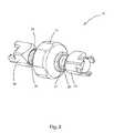
- FIG. 2is an enlarged perspective view a stabilizer of the dynamic stabilization assembly of FIG. 1 .
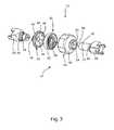
- FIG. 3is an exploded perspective view of the stabilizer of FIG. 2 .
- FIG. 4is a further exploded perspective view of the stabilizer of FIG. 2 .
- FIG. 5is a partially exploded perspective view of the stabilizer of FIG. 2 having two end caps.
- FIG. 6is a perspective view of the stabilizer of FIG. 2 , illustrating attachment of one end cap to an end coupling.
- FIG. 7is a perspective view of the stabilizer of FIG. 2 with attached end caps.
- FIG. 8is a partially exploded perspective view of the dynamic stabilization assembly of FIG. 1 .
- FIG. 9is a perspective view of two of the stabilizers of FIG. 2 , placed end to end, with two end caps being detached therefrom.
- FIG. 10is a perspective view of two of the stabilizers of FIG. 2 , placed end to end, with two end caps being attached thereto.
- FIG. 11is a perspective view of two stabilizers of FIG. 2 , placed end to end, illustrating the coupling of the ends of the stabilizers to each other.
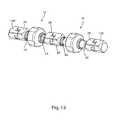
- FIG. 12is a perspective view of the stabilizer of FIG. 2 , coupled end-to-end with a second stabilizer for multi-level vertebral stabilization.
- FIG. 13is a perspective view of the two stabilizers of FIG. 12 , illustrating how the articulation components may be used to provide an overall curvature to the assembled modules.
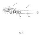
- FIG. 14is a perspective view of the stabilizer of FIG. 2 , coupled end-to-end with a rigid connector and an end cap for single level vertebral joint stabilization with joint immobilization at an adjacent level.
- FIG. 15is an exploded perspective view of the stabilizer and rigid connector of FIG. 14 , illustrating the coupling of the stabilizer and the rigid connector to each other.
- FIG. 16is a perspective view of the stabilizer and rigid connector of FIG. 14 , illustrating how the articulation components may be used to provide an overall curvature to the assembled modules.
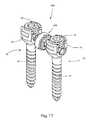
- FIG. 17is a perspective view of another dynamic stabilization assembly according to an alternative embodiment of the invention.
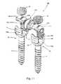
- FIG. 18is an enlarged perspective view of a stabilizer and end couplings of the dynamic stabilization assembly of FIG. 17 .
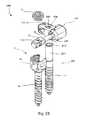
- FIG. 19is an exploded perspective view of the stabilizer of FIG. 18 .
- FIG. 20is an exploded perspective view of the stabilizer and end couplings of FIG. 18 .
- FIG. 21is a partially exploded perspective view of the dynamic stabilization assembly of FIG. 17 .
- FIG. 22is a perspective view of an overhung stabilizer and articulating component of an overhung dynamic stabilization assembly designed for shorter pedicle-to-pedicle displacements.
- FIG. 23is an exploded perspective view of the overhung stabilizer of FIG. 22 .
- FIG. 24is a partially exploded perspective view of an overhung dynamic stabilization assembly including the components of FIG. 22 .
- FIG. 25is another partially exploded perspective view of the overhung dynamic stabilization assembly of FIG. 24 .
- FIG. 26is a perspective view of a fully assembled overhung dynamic stabilization assembly of FIG. 24 .
- FIG. 27is a perspective view of the dynamic stabilization assembly including the stabilizer of FIG. 22 , along with the overhung stabilization assembly of FIG. 24 .
- FIG. 28is an exploded perspective view of the dynamic stabilization assembly of FIG. 27 .
- FIG. 29is a further exploded perspective view of the dynamic stabilization assembly of FIG. 27 .
- the present inventionrelates to systems and methods for stabilizing the relative motion of spinal vertebrae.
- Those of ordinary skill in the artwill recognize that the following description is merely illustrative of the principles of the invention, which may be applied in various ways to provide many different alternative embodiments. This description is understandably set forth for the purpose of illustrating the general principles of this invention and is not meant to limit the inventive concepts in the appended claims.
- the dynamic stabilization system 10preferably includes a stabilizer 12 , a pair of fixation members 14 , a pair of yokes 16 securable to the fixation members 14 , and a pair of set screws 18 .
- the fixation members 14 , yokes 16 , and set screws 18may be any of a variety of types known and available in the art, or may optionally be specially designed for operation with the stabilizer 12 .
- Each fixation member 14 with its corresponding yoke 16 and set screw 18provides an anchoring member 19 designed to anchor the stabilizer 12 to a pedicle or other portion of a vertebra (not shown).
- each yoke 16may be unitarily formed with a fixation member 14 as illustrated herein, or each yoke 16 may be a separate entity and be polyaxially securable to a fixation member 14 .
- stabilizer 12is illustrated alone in FIG. 2 .
- stabilizer 12includes a central spring casing 22 , and a short arm 26 extending from the spring casing 22 on one side to an articulation component 24 .
- a longer arm 27extends from the spring casing 22 to another articulation component 25 .
- An end coupling 28is also preferably located on the outside of each articulation component 24 , 25 . It is noted that the particular construction of stabilizer 12 depicted in FIG. 2 may vary. For example, the short arm 26 and longer arm 27 may be flipped to opposite sides.
- a planar spring 20is shown encased within the spring casing 22 .
- the planar spring 20is preferably coiled in a planar spiral-like shape and has a threaded inner ring surface 30 and an outer ring surface 32 .
- the spring casing 22is made up of two concentric hollow members, an inner hollow member 40 and an outer hollow member 42 , with the planar spring 20 being disposed within the inner hollow member 40 .
- a circular bore 44occupies the center of the inner hollow member 40 , creating a round opening from an inside surface 46 to an outside surface 48 .
- a protruding circular lip 49may also surround the bore 44 where it exits the outside surface 48 .
- An inner wall 52 of the lip 49is preferably threaded.
- a circular bore 54occupies the center of the outer hollow member 42 , creating a round opening from an inside surface 56 to an outside surface 58 .
- a protruding circular lip 59may also surround the bore 54 where it exits the outside surface 58 .
- the short arm 26Shown adjacent to the inner hollow member 40 is the short arm 26 , which has a threaded outer surface 76 on the end closest to the inner hollow member 40 . This end terminates at a flat end 36 . Both surface 76 and flat end 36 are best shown in FIG. 4 .
- the articulation component 24On the opposite end of the short arm 26 is the articulation component 24 , which terminates at the end coupling 28 .
- Adjacent to the outer hollow member 42is the long arm 27 , which has a threaded terminal segment 78 on the end closest to the outer hollow member 42 . The terminal segment terminates at a flat end 37 (best shown in FIG. 4 ).
- the articulation component 25On the opposite end of the long arm 27 is the articulation component 25 , which terminates at the end coupling 28 .
- the short arm 26When assembled, the short arm 26 fits inside the bore 44 of the inner hollow member 40 .
- the planar spring 20fits inside the inner hollow member 40 .
- the long arm 27fits through the bore 54 of the outer hollow member 42 , with the threaded terminal segment 78 engaging the threaded inner ring surface 30 of the planar spring 20 .
- the inner hollow member 40fits concentrically within the outer hollow member 42 , with the planar spring 20 also being disposed inside. Inside of the hollow members 40 , 42 , the flat ends 36 , 37 of the arms 26 , 27 are preferably adjacent to one another but not touching.
- the planar spring 20When assembled with the hollow members 40 , 42 and the arms 26 , 27 , the planar spring 20 can, if acted upon, flex out of the plane within which it is coiled.
- the spiral-like shape of the planar spring 20preferably extends out of its plane.
- the planar spring 20also preferably recoils back to its plane. During this extension and recoil, the inside surface 46 of the inner hollow member 40 , and the inside surface 56 of the outer hollow member 42 act as barriers to limit the movement of the planar spring 20 .
- planar spring 20As opposed to a longer helical spring, keeps the overall length of the stabilizer 12 relatively short.
- a planar spring according to the inventionneed not have a spiral-like shape, but can rather be a cantilevered leaf spring, a flexible disc, or the like. Further, in other alternative embodiments, a planar spring need not be used; rather, a different type of spring or a conventional helical spring may be used.
- FIG. 4illustrates the articulation components 24 , 25 in an exploded view.
- the articulation component 24is located adjacent to and couples with the inner hollow member 40
- the articulation component 25is located adjacent to and couples with the outer hollow member 42 .
- Each articulation component 24 , 25preferably comprises a semispherical surface 60 , a cup 62 , which are both enclosed by the end coupling 28 .
- the cup 62is preferably dish shaped, with a cylindrical support wall 64 and two ends. On one end of the cup 62 is a depression 66 , and on the opposite side of the cup 62 is a flat end 68 .
- the semispherical surface 60preferably has a round side 70 which rotatably fits inside the depression 66 , so that each of the articulation components 24 , 25 thus takes the form of a ball-and-socket joint.
- the opposite side of each semispherical surface 60is a connecting side 72 which narrows into a neck 74 .
- the neck 74preferably widens into either the short arm 26 or the long arm 27 , which extends away from the semispherical surface 60 on the opposite side from the round side 70 .
- the outer wall 76 of the short arm 26is threaded, as is the terminal segment 78 of the long arm 27 .
- articulation componentsmay be omitted, or may be formed by any other type of mechanical joints known in the art.
- the end coupling 28has a support wall 102 which forms the outer sides of the cup, and a base 104 .
- a circular hole 106occupies the center of the base 104 , and where the edge of the hole 106 meets the base 104 , a circular rim 108 preferably surrounds the hole 106 .
- the inside diameter of the rim 108is preferably less than the diameter of the semispherical surface 60 of the articulation components 24 and 25 , so that when assembled the semispherical surface 60 will fit into the end coupling 28 but not be capable of passing through the hole 106 .
- the support wall 102terminates in a flat edge 110 .
- a plurality of irregularly shaped teeth 112Protruding from the edge 110 in the same plane as the support wall 102 , such that they form continuations of the support wall 102 , is a plurality of irregularly shaped teeth 112 . Between each tooth 112 and the adjacent tooth is a notch 114 .
- each semispherical surface 60When assembled, the round side 70 of each semispherical surface 60 rotatably rests in the depression 66 of the cup 62 , and the arm 26 or 27 extends away from the joining side 72 of the semispherical surface 60 .
- the generally cup-shaped end coupling 28fits over each semispherical surface, arm and cup assembly.
- Each arm 26 , 27extends from its semispherical surface 60 through its respective hole 106 . As described above, the arms then extend into the spring casing 22 , the long arm 27 connecting to the planar spring 20 and the short arm 26 connecting to the inner hollow member 40 . Rotation of either semispherical surface 60 results in movement of its arm 26 , 27 .
- the flat end 37 of the opposite arm 27may optionally contact the flat end 36 of the short arm 26 to acts as a stop to limit excessive movement.
- the flat end 36 of the opposite short arm 26may stop excessive movement via contact with the flat end 37 of the long arm 27 .
- the articulation components 24 , 25secure the arms 26 , 27 in a rotatable manner to the spring casing 22 to permit the stabilizer 12 to obtain a variable curvature.
- FIG. 5illustrates one coupled stabilizer 12 , having a coupled end cap 120 and an uncoupled end cap 120 .
- Each end cap 120preferably has a general cup-shape, much like each end coupling 28 .
- Each end cap 120preferably includes a support wall 122 which forms the outer sides of the cup, and a solid base 124 which forms the bottom of the cup.
- the inside diameter of the end cap 120is sized to fit around either arm 26 , 27 .
- the support wall 122terminates in a flat edge 130 .
- a plurality of irregularly shaped teeth 132Protruding from the edge 130 in the same plane as the support wall 122 , such that they form continuations of the support wall 122 , are a plurality of irregularly shaped teeth 132 . Between each tooth 132 and the adjacent tooth is a notch 134 .
- an end cap 120is illustrated in partial engagement to a stabilizer 12 .
- the end cap 120is preferably lined up with the end coupling 28 so that the teeth 112 , 132 are pointed toward one another.
- the end cap 120is then rotated and moved toward the end coupling 28 so that the teeth 132 fit into the notches 114 , while the teeth 112 fit into the notches 134 .
- the support walls 144Alternating between the support walls 144 are two opposing gaps 146 , which form a cavity 148 therebetween that occupies the interior of the yoke 16 .
- the inner surfaces 150 of the support walls 144are also preferably threaded to engage a set screw 18 .
- the stabilizer 12in use, is inserted into the yokes 16 of two anchoring members 19 whose fixation members 14 have previously been anchored in the pedicles, or other portion, of the corresponding vertebrae.
- the stabilizer 12is laid lengthwise into the yokes 16 such that the long axis of the stabilizer 12 is perpendicular to the long axes of the fixation members 14 , and so that the spring casing 22 lies between the anchoring members 19 .
- Each end coupling 28 /end cap 120 pairpreferably rests on the head 142 within the cavity 148 .
- Each end cappreferably occupies the gaps 146 , and the two articulation components 24 , 25 lie adjacent to, but outside of, the two interior gaps 146 .
- an alternative embodiment of the inventionincludes yokes 16 which are separate entities from the fixation members 14 , and are polyaxially securable to the fixation members 14 .
- FIG. 9two assembled stabilizers 12 are illustrated positioned end-to end with two end caps 120 positioned at the outer ends of the stabilizers 12 .
- Two stabilizers 12may be interlocked with each other end-to-end and implanted when it is desirable to stabilize the relative motion of three adjacent vertebrae.
- FIG. 10depicts a similar assembly, with two stabilizers 12 being illustrated end-to-end, and one end cap 120 being secured to each outer end coupling 28 in a similar fashion to that previously depicted in FIG. 7 .
- the teeth 112 of each end coupling 28are aligned to fit into the notches 114 of the facing end coupling 28 .
- FIG. 10depicts a similar assembly, with two stabilizers 12 being illustrated end-to-end, and one end cap 120 being secured to each outer end coupling 28 in a similar fashion to that previously depicted in FIG. 7 .
- the teeth 112 of each end coupling 28are aligned to fit into the notches 114 of the facing end coupling 28
- FIG. 11depicts the two stabilizers 12 in an end-to-end fashion and partially interlocked together.
- the teeth 112 of each facing end coupling 28are in the notches 114 of the opposite end coupling 28 , and the stabilizers 12 have been partially turned so that the teeth 112 are partially interlocked.
- FIG. 12the two stabilizers 12 are shown completely interlocked end-to-end.
- the end couplings 28 of the two stabilizers 12are rotated into locking engagement with each other and an end cap 120 is locked onto each unoccupied external end coupling 28 .
- the entire dynamic stabilization assemblyhas four articulation components 24 , 25 , which will permit considerable differentiation in orientation between the three fixation members 14 that would be used to attach the stabilizers 12 to three adjacent vertebrae (not shown).
- FIG. 13two interlocked stabilizers 12 are illustrated with the articulation components 24 , 25 in an articulated position so that the stabilizers 12 no longer lie in a straight line, but instead the multi-level dynamic stabilization assembly approximates a curve.
- Thisenables the assembly to conform to the desired lordotic curve of the lower spine or to other spinal curvatures, such as those caused by or used to correct scoliosis. Additional levels can be added if desired.
- a stabilizer 12is depicted secured end-to-end to a rigid connector 160 to provide dynamic stabilization across one level, and posterior immobilization and/or fusion across the adjacent level.
- the rigid connector 160has a rod 162 and an end coupling 164 .
- the end coupling 164is toothed and notched so that it may engage the end coupling 28 on the stabilizer 12 . This is not unlike the other couplings discussed above.
- the rod 162may be secured in the yoke 16 of a fixation member 14 with a set screw 18 .
- interlocked end coupling 164 /end coupling 28 combinationmay be secured in the yoke 16 of an anchoring member 19 in a manner similar to the previously described securing of the end couplings and end caps. Additional rigid connectors 160 or stabilizers 12 with associated anchoring members 19 can be added if additional levels are desired.
- FIG. 15depicts an exploded view of the system depicted in FIG. 14 , having one stabilizer 12 , an end cap 120 , and one rigid connector 160 .
- the end coupling 164has teeth 166 protruding from one end, and notches 167 between the teeth.
- the teeth 166 of the end coupling 164fit into the notches 114 of the end coupling 28 .
- the teeth 112 of the end coupling 28fit into the notches 167 of the end coupling 164 .
- the stabilizer 12 and the rigid connector 160are rotated in opposite directions so that the teeth 112 , 166 interlock and the stabilizer 112 and the rigid connector 160 are locked together.
- FIG. 16depicts one stabilizer 12 interlocked with a rigid connector 160 and an end cap 120 , and in a position with components 24 , 25 being articulated to allow the assembly to approximate a curve.
- dynamic stabilization across one level and posterior immobilization and/or fusion across the adjacent levelmay be accomplished while simultaneously following the desired curvature of the spine.
- a rigid connector 160 with an end coupling 164 at each endcould be used, allowing a stabilization module 12 to couple to each end of the rigid connector 160 .
- FIG. 17an alternative embodiment of a stabilization system 168 is depicted.
- a stabilizer 170is secured to two anchoring members 19 .
- the anchoring members 19each preferably include two yokes 16 connected with two fixation members 14 , and two set screws 18 are preferably used to hold the stabilizer 170 in place.
- the stabilizer 170has a spring casing 172 and two articulation components 174 , 175 .
- a two-piece end housing 178also preferably extends from either articulation component 174 , 175 .
- the spring casing 172preferably houses a planar spring 180 .
- the planar spring 180has a first side 182 and a second side 183 . Extending from the first side 182 is an arm 184 which narrows into a neck 186 and terminates in a semispherical surface 188 .
- the spring casing 172has an outer hollow member 190 and an inner hollow member 192 .
- the inner hollow member 192is of a shallow dish shape, and has a circular plate 194 which forms the base of the hollow member, with a threaded outer rim 196 which encircles the outside of the plate 194 .
- An inner rim 198encircles a round hole 200 in the center of the plate 194 .
- the planar spring 180When assembled, the planar spring 180 preferably fits into the cavity 202 of the outer hollow member 190 , with the second side 183 adjacent to the plate 204 of the hollow member 190 .
- the inner hollow member 192fits over the planar spring 180 , so that the arm 184 and the semispherical surface 188 extend through the hole 200 in the inner hollow member 192 .
- the threads on the outer rim 196engage with the threads on the inner surface 208 of the outer hollow member 190 , joining the hollow members 190 , 192 to form the casing 172 .
- the spring 180is thusly captured inside the casing 172 , which prevents it from moving axially.
- the planar spring 180When the arm 184 moves toward or away from the outer hollow member 190 , the planar spring 180 extends out of its plane. When the arm 184 returns to its original position, the planar spring 180 recoils back towards its plane. During this extension and recoiling, the plate 194 of the inner hollow member 192 and the plate 204 of the outer hollow member 190 act as barriers to limit the movement of the planar spring 180 .
- the arm 184is encircled by the inner rim 198 , which acts as a bearing surface to prevent radial movement of the arm relative to the inferior hollow member 192 .
- a coupling in the form of a two-part end housing 178fits over each semispherical surface 188 , 212 .
- Each end housing 178has a first wall 220 and a second wall 222 .
- the first wall 220is shaped like a segment of a cylindrical body that is split lengthwise, and has an inner surface 224 and rounded outer surface 226 .
- a rounded first hollow 228is indented into the inner surface 224 .
- Indented into the inner surface 224 , between the hollows 228are two receiving holes 230 .
- the second wall 222is also shaped like a segment of a cylindrical body and has an inner surface 234 and an outer surface 236 .
- the outer surface 236is not rounded but is squared off so it is flat.
- the inner surface 234has a rounded second hollow 238 indented into each lengthwise end. Each pair of rounded hollows 228 , 238 cooperates to define a socket sized to receive the corresponding ball 188 or 212 .
- Two pin holes 240extend from the outer surface 236 through the wall 222 to the inner surface 234 , such that two pins 242 can fit through the pin holes 240 and into the receiving holes 230 in the first wall 220 .
- the assembled stabilizer 170fits into the yokes 16 of two anchoring members 19 , as is best shown in FIG. 17 (shown disassembled in FIG. 21 ).
- the end housings 178are preferably situated perpendicular to the fixation members 14 , so that the end housings 178 fit between support walls 144 of anchoring member 19 , and the rounded outer surface 226 is cradled on a curved floor 142 between walls 144 .
- Two set screws 18are thereafter engaged in the threads 150 and tightened. The tightening of the set screws 18 creates pressure on the end housings 178 , holding the housings closed around the semispherical surfaces 188 , 212 .
- each anchoring member 19may comprise a unitary piece which includes both the fixation member 14 and the yoke 16 , or the fixation member 14 and the yoke 16 may be separate pieces. In such an embodiment where the fixation member 14 and yokes 16 are separate pieces, tightening of the set screws 18 may also press the end housings 178 against the heads 142 of the fixation members 14 , thereby restricting further rotation of the yokes 16 with respect to the fixation members 14 to secure the entire assembly.
- a stabilizer 170can also be employed in combination with a rigid connector to provide dynamic stabilization across one level and posterior fusion across the adjacent level. Additional levels may be added as desired. Multiple stabilization/fusion levels can include two or more sequential rigid connectors, or rigid connecters sequentially interspersed with stabilizers.
- FIG. 23depicts an exploded view of the stabilizer 250 in more detail.
- the housing 252has a chamber 262 which holds the articulation component 254 .
- a threaded cap 264is screwed into the housing 252 closing off one end of the chamber 262 .
- a planar spring 266 with a threaded inner ring 268is positioned within the cap 264 .
- Releasably screwed to the inner ring 268is a socket 270 with a threaded end stud 272 .
- a cup 274terminates the socket 270 at the end opposite the threaded end stud 272 .
- a semispherical surface 276is connected to the arm 256 , and the semispherical surface 276 rotatably rests in the cup 274 .
- a tubular sleeve 278surrounds the socket 270 , semispherical surface 276 and arm 256 .
- the sleeve 278has a central bore 280 through which the arm 256 protrudes.
- the sleeve 278also has two grooves 282 which run lengthwise down opposite outer sides of the sleeve.
- the pins 284are inserted through two pin holes 286 which perforate the outer wall of the housing 252 .
- the inserted pins 284fit into the grooves 282 , and prevent the sleeve 278 and its enclosed contents from moving axially.
- FIG. 24An unassembled stabilization system 248 is shown in FIG. 24 .
- the system 248includes the overhung stabilizer 250 , an anchoring member 19 , an anchoring member 288 , an articulation component 24 , an end coupling 28 and an end cap 120 .
- the anchoring member 19has a fixation member 14 , a yoke 16 and a set screw 18 .
- the anchoring member 288comprises a fixation member 14 and an extension post 290 .
- the fixation members 14may comprise pedicle screws, screws fixed to other parts of the vertebrae, pins, clips, clamps, adhesive members, or any other device capable of anchoring the stabilizer to the vertebrae.
- each yoke 16may be unitarily formed with a fixation member 14 as illustrated herein, or each yoke 16 may be a separate entity and be polyaxially securable to a fixation member 14 .
- the articulation component 24has a tubular joining arm 292 extending from an end coupling 28 .
- the joining arm 292is shaped to fit over the end of the arm 256 which protrudes from the articulation component 254 .
- FIG. 25illustrates the stabilization system 248 in a partially assembled state.
- the stabilizer 250is joined to the articulation component 24 and end coupling 28 , with the joining arm 292 fitting over the end of the arm 256 which protrudes from the articulation component 254 through the use of a press fit or other attachment mechanism.
- the end cap 120fits on the opposite end of the end coupling 28 , in the manner previously described.
- the fully assembled stabilization system 248is shown in FIG. 26 . In this assembly, the end coupling 28 and end cap 120 fit in the yoke 16 of the anchoring member 19 , and are held in place by tightening the set screw 18 , in the same manner set forth previously.
- the assembled stabilizer 250is placed over the anchoring member 288 , with the extension post 290 on the anchoring member 288 extending posteriorly through the tunnel 258 .
- the set screws 259are engaged in the outer wall of the housing 252 adjacent to the extension post 290 .
- the set screws 259are tightened, they push against the flexible stop 260 , which in turn pushes against the post 290 , holding the stabilizer 250 in place on the extension post 290 .
- the joining arm 292connects the articulation component 24 to the articulation component 254 , thus pivotably connecting the stabilizer 250 , secured to the anchoring member 288 , to the anchoring member 19 .
- planar spring 266When the system 248 is fully assembled and anchored to two adjacent vertebrae, motion between the two vertebrae can cause the planar spring 266 to flex out of its plane. Referring back to FIG. 23 , when the two adjacent vertebrae move closer together and the distance between them shortens, the planar spring 266 returns to its plane. When the two adjacent vertebrae move apart and the distance between them lengthens, the planar spring 266 flexes in the opposite direction along the spiral path, toward the sleeve 278 . As the planar spring 266 flexes, the sleeve 278 which holds the articulation component 254 slides along the chamber 262 .
- the grooves 282allow the sleeve 278 to slide back and forth past the pins 284 , but the pins 284 restrict axial movement of the sleeve 278 and serve as stops to prevent the sleeve 278 from moving completely out of the chamber 262 .
- a multi-level dynamic stabilization systemwhich includes a stabilizer 12 as per FIGS. 1-8 , and an overhung stabilizer 250 as per FIGS. 22-26 .
- the stabilizer 12is mounted on two anchoring members 19 and connected via the joining arm 292 to the overhung stabilizer 250 which is mounted an anchoring member 288 .
- the resulting dynamic stabilization systemprovides stabilization across two adjacent vertebral levels.
- the overhung stabilizer 250allows one of the levels to have a relatively short pedicle-to-pedicle displacement.
- FIG. 28illustrates the stabilizers 12 , 250 , two anchoring members 19 and one anchoring member 288 in an exploded view.
- Each anchoring members 19includes a fixation member 14 , a yoke 16 and a set screw 18 , as set forth previously.
- the anchoring member 288includes a fixation member 14 with an extension post 290 , as set forth previously.
- the stabilizer 12has two end couplings 28 , one end coupling 28 connecting with one end cap 120 thereby forming a coupling mountable in a yoke 16 .
- the second end coupling 28 of the stabilizer 12preferably couples with the end coupling 28 that connects to the joining arm 292 , forming a coupling mountable in another yoke 16 .
- the joining arm 292fits over the arm 256 of the stabilizer 250 , thus connecting the stabilizer 250 to the stabilizer 12 .
- the stabilizer 250is mountable on the anchoring member 288 , in the manner set forth previously.
- this two level systemWhen assembled, this two level system has two articulation components 24 , one articulation component 25 , and one articulation component 254 , providing pivotability between the stabilized vertebrae. Additionally, an overhung stabilizer 250 , a stabilizer 12 , and/or a stabilizer 170 such as that depicted in FIGS. 17-21 can be implanted in combination with a rigid connector 160 such as that depicted in FIGS. 14-16 .
Landscapes
- Health & Medical Sciences (AREA)
- Orthopedic Medicine & Surgery (AREA)
- Life Sciences & Earth Sciences (AREA)
- Neurology (AREA)
- Surgery (AREA)
- Heart & Thoracic Surgery (AREA)
- Engineering & Computer Science (AREA)
- Biomedical Technology (AREA)
- Nuclear Medicine, Radiotherapy & Molecular Imaging (AREA)
- Medical Informatics (AREA)
- Molecular Biology (AREA)
- Animal Behavior & Ethology (AREA)
- General Health & Medical Sciences (AREA)
- Public Health (AREA)
- Veterinary Medicine (AREA)
- Surgical Instruments (AREA)
- Prostheses (AREA)
Abstract
Description
Claims (20)
Priority Applications (1)
| Application Number | Priority Date | Filing Date | Title |
|---|---|---|---|
| US15/258,468US10004539B2 (en) | 2005-10-31 | 2016-09-07 | System and method for dynamic vertebral stabilization |
Applications Claiming Priority (6)
| Application Number | Priority Date | Filing Date | Title |
|---|---|---|---|
| US73226505P | 2005-10-31 | 2005-10-31 | |
| US11/589,512US8109973B2 (en) | 2005-10-31 | 2006-10-30 | Method for dynamic vertebral stabilization |
| US11/589,648US8137385B2 (en) | 2005-10-31 | 2006-10-30 | System and method for dynamic vertebral stabilization |
| US13/350,236US8623059B2 (en) | 2005-10-31 | 2012-01-13 | System and method for dynamic vertebral stabilization |
| US14/102,158US9445846B2 (en) | 2005-10-31 | 2013-12-10 | System and method for dynamic vertebral stabilization |
| US15/258,468US10004539B2 (en) | 2005-10-31 | 2016-09-07 | System and method for dynamic vertebral stabilization |
Related Parent Applications (1)
| Application Number | Title | Priority Date | Filing Date |
|---|---|---|---|
| US14/102,158ContinuationUS9445846B2 (en) | 2005-10-31 | 2013-12-10 | System and method for dynamic vertebral stabilization |
Publications (2)
| Publication Number | Publication Date |
|---|---|
| US20160374729A1 US20160374729A1 (en) | 2016-12-29 |
| US10004539B2true US10004539B2 (en) | 2018-06-26 |
Family
ID=38441848
Family Applications (6)
| Application Number | Title | Priority Date | Filing Date |
|---|---|---|---|
| US11/589,648Expired - Fee RelatedUS8137385B2 (en) | 2005-10-31 | 2006-10-30 | System and method for dynamic vertebral stabilization |
| US11/589,512Expired - Fee RelatedUS8109973B2 (en) | 2005-10-31 | 2006-10-30 | Method for dynamic vertebral stabilization |
| US13/350,236Expired - Fee RelatedUS8623059B2 (en) | 2005-10-31 | 2012-01-13 | System and method for dynamic vertebral stabilization |
| US13/356,947Expired - Fee RelatedUS8529603B2 (en) | 2005-10-31 | 2012-01-24 | System and method for dynamic vertebral stabilization |
| US14/102,158Active2027-03-28US9445846B2 (en) | 2005-10-31 | 2013-12-10 | System and method for dynamic vertebral stabilization |
| US15/258,468Expired - Fee RelatedUS10004539B2 (en) | 2005-10-31 | 2016-09-07 | System and method for dynamic vertebral stabilization |
Family Applications Before (5)
| Application Number | Title | Priority Date | Filing Date |
|---|---|---|---|
| US11/589,648Expired - Fee RelatedUS8137385B2 (en) | 2005-10-31 | 2006-10-30 | System and method for dynamic vertebral stabilization |
| US11/589,512Expired - Fee RelatedUS8109973B2 (en) | 2005-10-31 | 2006-10-30 | Method for dynamic vertebral stabilization |
| US13/350,236Expired - Fee RelatedUS8623059B2 (en) | 2005-10-31 | 2012-01-13 | System and method for dynamic vertebral stabilization |
| US13/356,947Expired - Fee RelatedUS8529603B2 (en) | 2005-10-31 | 2012-01-24 | System and method for dynamic vertebral stabilization |
| US14/102,158Active2027-03-28US9445846B2 (en) | 2005-10-31 | 2013-12-10 | System and method for dynamic vertebral stabilization |
Country Status (6)
| Country | Link |
|---|---|
| US (6) | US8137385B2 (en) |
| EP (1) | EP1942836B1 (en) |
| JP (1) | JP5072851B2 (en) |
| AU (1) | AU2006308954B2 (en) |
| CA (1) | CA2625305C (en) |
| WO (1) | WO2007053566A2 (en) |
Cited By (1)
| Publication number | Priority date | Publication date | Assignee | Title |
|---|---|---|---|---|
| US11583318B2 (en) | 2018-12-21 | 2023-02-21 | Paradigm Spine, Llc | Modular spine stabilization system and associated instruments |
Families Citing this family (76)
| Publication number | Priority date | Publication date | Assignee | Title |
|---|---|---|---|---|
| FR2812185B1 (en) | 2000-07-25 | 2003-02-28 | Spine Next Sa | SEMI-RIGID CONNECTION PIECE FOR RACHIS STABILIZATION |
| US7833250B2 (en) | 2004-11-10 | 2010-11-16 | Jackson Roger P | Polyaxial bone screw with helically wound capture connection |
| US8292926B2 (en) | 2005-09-30 | 2012-10-23 | Jackson Roger P | Dynamic stabilization connecting member with elastic core and outer sleeve |
| US7862587B2 (en) | 2004-02-27 | 2011-01-04 | Jackson Roger P | Dynamic stabilization assemblies, tool set and method |
| US8353932B2 (en) | 2005-09-30 | 2013-01-15 | Jackson Roger P | Polyaxial bone anchor assembly with one-piece closure, pressure insert and plastic elongate member |
| US10258382B2 (en) | 2007-01-18 | 2019-04-16 | Roger P. Jackson | Rod-cord dynamic connection assemblies with slidable bone anchor attachment members along the cord |
| US10729469B2 (en) | 2006-01-09 | 2020-08-04 | Roger P. Jackson | Flexible spinal stabilization assembly with spacer having off-axis core member |
| US8876868B2 (en) | 2002-09-06 | 2014-11-04 | Roger P. Jackson | Helical guide and advancement flange with radially loaded lip |
| WO2006052796A2 (en) | 2004-11-10 | 2006-05-18 | Jackson Roger P | Helical guide and advancement flange with break-off extensions |
| US7621918B2 (en) | 2004-11-23 | 2009-11-24 | Jackson Roger P | Spinal fixation tool set and method |
| US7377923B2 (en) | 2003-05-22 | 2008-05-27 | Alphatec Spine, Inc. | Variable angle spinal screw assembly |
| US8092500B2 (en) | 2007-05-01 | 2012-01-10 | Jackson Roger P | Dynamic stabilization connecting member with floating core, compression spacer and over-mold |
| US8926670B2 (en) | 2003-06-18 | 2015-01-06 | Roger P. Jackson | Polyaxial bone screw assembly |
| US7766915B2 (en) | 2004-02-27 | 2010-08-03 | Jackson Roger P | Dynamic fixation assemblies with inner core and outer coil-like member |
| US7776067B2 (en) | 2005-05-27 | 2010-08-17 | Jackson Roger P | Polyaxial bone screw with shank articulation pressure insert and method |
| US7967850B2 (en) | 2003-06-18 | 2011-06-28 | Jackson Roger P | Polyaxial bone anchor with helical capture connection, insert and dual locking assembly |
| US8366753B2 (en) | 2003-06-18 | 2013-02-05 | Jackson Roger P | Polyaxial bone screw assembly with fixed retaining structure |
| US7967826B2 (en)* | 2003-10-21 | 2011-06-28 | Theken Spine, Llc | Connector transfer tool for internal structure stabilization systems |
| US7588575B2 (en) | 2003-10-21 | 2009-09-15 | Innovative Spinal Technologies | Extension for use with stabilization systems for internal structures |
| US7179261B2 (en) | 2003-12-16 | 2007-02-20 | Depuy Spine, Inc. | Percutaneous access devices and bone anchor assemblies |
| US11419642B2 (en) | 2003-12-16 | 2022-08-23 | Medos International Sarl | Percutaneous access devices and bone anchor assemblies |
| US7527638B2 (en) | 2003-12-16 | 2009-05-05 | Depuy Spine, Inc. | Methods and devices for minimally invasive spinal fixation element placement |
| US8029548B2 (en) | 2008-05-05 | 2011-10-04 | Warsaw Orthopedic, Inc. | Flexible spinal stabilization element and system |
| US11241261B2 (en) | 2005-09-30 | 2022-02-08 | Roger P Jackson | Apparatus and method for soft spinal stabilization using a tensionable cord and releasable end structure |
| US8152810B2 (en) | 2004-11-23 | 2012-04-10 | Jackson Roger P | Spinal fixation tool set and method |
| US7160300B2 (en) | 2004-02-27 | 2007-01-09 | Jackson Roger P | Orthopedic implant rod reduction tool set and method |
| JP2007525274A (en) | 2004-02-27 | 2007-09-06 | ロジャー・ピー・ジャクソン | Orthopedic implant rod reduction instrument set and method |
| US7651502B2 (en) | 2004-09-24 | 2010-01-26 | Jackson Roger P | Spinal fixation tool set and method for rod reduction and fastener insertion |
| US8926672B2 (en) | 2004-11-10 | 2015-01-06 | Roger P. Jackson | Splay control closure for open bone anchor |
| US9168069B2 (en) | 2009-06-15 | 2015-10-27 | Roger P. Jackson | Polyaxial bone anchor with pop-on shank and winged insert with lower skirt for engaging a friction fit retainer |
| US8444681B2 (en) | 2009-06-15 | 2013-05-21 | Roger P. Jackson | Polyaxial bone anchor with pop-on shank, friction fit retainer and winged insert |
| US9980753B2 (en) | 2009-06-15 | 2018-05-29 | Roger P Jackson | pivotal anchor with snap-in-place insert having rotation blocking extensions |
| WO2006057837A1 (en) | 2004-11-23 | 2006-06-01 | Jackson Roger P | Spinal fixation tool attachment structure |
| US9216041B2 (en) | 2009-06-15 | 2015-12-22 | Roger P. Jackson | Spinal connecting members with tensioned cords and rigid sleeves for engaging compression inserts |
| US7901437B2 (en) | 2007-01-26 | 2011-03-08 | Jackson Roger P | Dynamic stabilization member with molded connection |
| US10076361B2 (en) | 2005-02-22 | 2018-09-18 | Roger P. Jackson | Polyaxial bone screw with spherical capture, compression and alignment and retention structures |
| US7604654B2 (en) | 2005-02-22 | 2009-10-20 | Stryker Spine | Apparatus and method for dynamic vertebral stabilization |
| US8105368B2 (en) | 2005-09-30 | 2012-01-31 | Jackson Roger P | Dynamic stabilization connecting member with slitted core and outer sleeve |
| US8034078B2 (en)* | 2008-05-30 | 2011-10-11 | Globus Medical, Inc. | System and method for replacement of spinal motion segment |
| USD589147S1 (en)* | 2006-02-02 | 2009-03-24 | Innovative Spinal Technologies | Bone anchor head |
| CA2670988C (en) | 2006-12-08 | 2014-03-25 | Roger P. Jackson | Tool system for dynamic spinal implants |
| US8366745B2 (en) | 2007-05-01 | 2013-02-05 | Jackson Roger P | Dynamic stabilization assembly having pre-compressed spacers with differential displacements |
| US8475498B2 (en) | 2007-01-18 | 2013-07-02 | Roger P. Jackson | Dynamic stabilization connecting member with cord connection |
| US8109975B2 (en)* | 2007-01-30 | 2012-02-07 | Warsaw Orthopedic, Inc. | Collar bore configuration for dynamic spinal stabilization assembly |
| US9414861B2 (en) | 2007-02-09 | 2016-08-16 | Transcendental Spine, Llc | Dynamic stabilization device |
| US8926667B2 (en)* | 2007-02-09 | 2015-01-06 | Transcendental Spine, Llc | Connector |
| US8012177B2 (en) | 2007-02-12 | 2011-09-06 | Jackson Roger P | Dynamic stabilization assembly with frusto-conical connection |
| US8979904B2 (en) | 2007-05-01 | 2015-03-17 | Roger P Jackson | Connecting member with tensioned cord, low profile rigid sleeve and spacer with torsion control |
| US10383660B2 (en) | 2007-05-01 | 2019-08-20 | Roger P. Jackson | Soft stabilization assemblies with pretensioned cords |
| CA2690038C (en) | 2007-05-31 | 2012-11-27 | Roger P. Jackson | Dynamic stabilization connecting member with pre-tensioned solid core |
| US8911477B2 (en) | 2007-10-23 | 2014-12-16 | Roger P. Jackson | Dynamic stabilization member with end plate support and cable core extension |
| US20090248077A1 (en)* | 2008-03-31 | 2009-10-01 | Derrick William Johns | Hybrid dynamic stabilization |
| WO2009132305A2 (en)* | 2008-04-24 | 2009-10-29 | Alpinespine Llc | Rotolock cervical plate locking mechanism |
| AU2010260521C1 (en) | 2008-08-01 | 2013-08-01 | Roger P. Jackson | Longitudinal connecting member with sleeved tensioned cords |
| US8287571B2 (en) | 2008-08-12 | 2012-10-16 | Blackstone Medical, Inc. | Apparatus for stabilizing vertebral bodies |
| EP2153786B1 (en) | 2008-08-12 | 2011-10-26 | BIEDERMANN MOTECH GmbH | Modular system for the stabilization of the spinal column |
| US11229457B2 (en) | 2009-06-15 | 2022-01-25 | Roger P. Jackson | Pivotal bone anchor assembly with insert tool deployment |
| US8998959B2 (en) | 2009-06-15 | 2015-04-07 | Roger P Jackson | Polyaxial bone anchors with pop-on shank, fully constrained friction fit retainer and lock and release insert |
| CN103826560A (en) | 2009-06-15 | 2014-05-28 | 罗杰.P.杰克逊 | Polyaxial Bone Anchor with Socket Stem and Winged Inserts with Friction Fit Compression Collars |
| US9668771B2 (en) | 2009-06-15 | 2017-06-06 | Roger P Jackson | Soft stabilization assemblies with off-set connector |
| EP2485654B1 (en) | 2009-10-05 | 2021-05-05 | Jackson P. Roger | Polyaxial bone anchor with non-pivotable retainer and pop-on shank, some with friction fit |
| WO2011063020A1 (en)* | 2009-11-18 | 2011-05-26 | Seaspine, Inc. | Flexible screw head constructs for spinal stabilization |
| AU2011299558A1 (en) | 2010-09-08 | 2013-05-02 | Roger P. Jackson | Dynamic stabilization members with elastic and inelastic sections |
| AU2011324058A1 (en) | 2010-11-02 | 2013-06-20 | Roger P. Jackson | Polyaxial bone anchor with pop-on shank and pivotable retainer |
| JP5865479B2 (en) | 2011-03-24 | 2016-02-17 | ロジャー・ピー・ジャクソン | Multiaxial bone anchor with compound joint and pop-mounted shank |
| US9144506B2 (en)* | 2011-08-11 | 2015-09-29 | Jeff Phelps | Interbody axis cage |
| US20130090690A1 (en)* | 2011-10-06 | 2013-04-11 | David A. Walsh | Dynamic Rod Assembly |
| US8911479B2 (en) | 2012-01-10 | 2014-12-16 | Roger P. Jackson | Multi-start closures for open implants |
| US8911478B2 (en) | 2012-11-21 | 2014-12-16 | Roger P. Jackson | Splay control closure for open bone anchor |
| US10058354B2 (en) | 2013-01-28 | 2018-08-28 | Roger P. Jackson | Pivotal bone anchor assembly with frictional shank head seating surfaces |
| US8852239B2 (en) | 2013-02-15 | 2014-10-07 | Roger P Jackson | Sagittal angle screw with integral shank and receiver |
| US9566092B2 (en) | 2013-10-29 | 2017-02-14 | Roger P. Jackson | Cervical bone anchor with collet retainer and outer locking sleeve |
| US9717533B2 (en) | 2013-12-12 | 2017-08-01 | Roger P. Jackson | Bone anchor closure pivot-splay control flange form guide and advancement structure |
| US9451993B2 (en) | 2014-01-09 | 2016-09-27 | Roger P. Jackson | Bi-radial pop-on cervical bone anchor |
| US9597119B2 (en) | 2014-06-04 | 2017-03-21 | Roger P. Jackson | Polyaxial bone anchor with polymer sleeve |
| US10064658B2 (en) | 2014-06-04 | 2018-09-04 | Roger P. Jackson | Polyaxial bone anchor with insert guides |
Citations (188)
| Publication number | Priority date | Publication date | Assignee | Title |
|---|---|---|---|---|
| US895492A (en) | 1906-05-18 | 1908-08-11 | Percy John Neate | Spring. |
| US3599245A (en) | 1968-06-26 | 1971-08-17 | Blatchford & Sons Ltd | Artificial leg having a preset automatic friction band tension control |
| US3778610A (en) | 1972-12-04 | 1973-12-11 | L Wolf | Adjustable joint for electrical fixtures |
| US4097071A (en) | 1977-06-06 | 1978-06-27 | General Motors Corporation | Flexible exhaust coupling |
| DE2821678A1 (en) | 1978-05-12 | 1979-11-22 | Sulzer Ag | IMPLANT THAT CAN BE INSERTED BETWEEN NEIGHBORING Vertebrae |
| US4181208A (en) | 1978-05-18 | 1980-01-01 | General Motors Corporation | Vibration damper with three sets of springs in parallel |
| US4369769A (en) | 1980-06-13 | 1983-01-25 | Edwards Charles C | Spinal fixation device and method |
| US4408601A (en) | 1980-04-14 | 1983-10-11 | Wilh, Wenk Ag | Bone compression plate |
| US4479623A (en) | 1982-12-10 | 1984-10-30 | The Boeing Company | Spring operated counterbalance hinge assembly for aircraft doors |
| US4743260A (en) | 1985-06-10 | 1988-05-10 | Burton Charles V | Method for a flexible stabilization system for a vertebral column |
| EP0322334A1 (en) | 1987-12-23 | 1989-06-28 | Cremascoli France | Prosthesis implanted between vertebral spinous processes |
| US4919403A (en) | 1986-10-07 | 1990-04-24 | Proprietary Technology, Inc. | Serpentine strip spring |
| US4947835A (en) | 1989-04-05 | 1990-08-14 | Dynasplint Systems, Inc. | Adjustable splint assembly |
| US5034011A (en) | 1990-08-09 | 1991-07-23 | Advanced Spine Fixation Systems Incorporated | Segmental instrumentation of the posterior spine |
| US5036837A (en) | 1990-02-09 | 1991-08-06 | Bio-Tec, Inc. | Dynamic extension splint |
| US5092866A (en) | 1989-02-03 | 1992-03-03 | Breard Francis H | Flexible inter-vertebral stabilizer as well as process and apparatus for determining or verifying its tension before installation on the spinal column |
| US5180393A (en) | 1990-09-21 | 1993-01-19 | Polyclinique De Bourgogne & Les Hortensiad | Artificial ligament for the spine |
| FR2680461A1 (en) | 1991-08-19 | 1993-02-26 | Sofamor | IMPLANT FOR OSTEOSYNTHESIS DEVICE, ESPECIALLY OF THE RACHIS, AND CORRESPONDING DEVICE FOR ITS PLACEMENT. |
| US5236460A (en) | 1990-02-12 | 1993-08-17 | Midas Rex Pneumatic Tools, Inc. | Vertebral body prosthesis |
| US5254967A (en) | 1992-10-02 | 1993-10-19 | Nor-Am Electrical Limited | Dual element fuse |
| WO1994021185A1 (en) | 1993-03-24 | 1994-09-29 | University Of Miami | Implantable spinal assist device |
| JPH06285100A (en) | 1993-02-17 | 1994-10-11 | Psi | Relief device as prosthesis for stabilizing interbody |
| FR2704137A1 (en) | 1993-04-20 | 1994-10-28 | Biotecnic Sa | Spinal osteosynthesis device |
| US5375823A (en) | 1992-06-25 | 1994-12-27 | Societe Psi | Application of an improved damper to an intervertebral stabilization device |
| WO1995005783A1 (en) | 1993-08-27 | 1995-03-02 | Fairant, Paulette | Dynamic implanted vertebral orthesis |
| US5407397A (en) | 1993-09-21 | 1995-04-18 | Dayco Products, Inc. | Belt tensioner, components therefor and methods of making the same |
| EP0669109A1 (en) | 1994-02-28 | 1995-08-30 | SULZER Medizinaltechnik AG | Stabilizer for adjacent vertebrae |
| FR2717370A1 (en) | 1994-03-18 | 1995-09-22 | Moreau Patrice | Intervertebral stabilising prosthesis for spinal reinforcement inserted during spinal surgery |
| EP0677277A2 (en) | 1994-03-18 | 1995-10-18 | Patrice Moreau | Spinal prosthetic assembly |
| DE9419900U1 (en) | 1994-12-15 | 1996-04-18 | Schäfer micomed GmbH, 73614 Schorndorf | Osteosynthesis device |
| US5520627A (en) | 1993-06-30 | 1996-05-28 | Empi, Inc. | Range-of-motion ankle splint |
| US5522214A (en) | 1993-07-30 | 1996-06-04 | Stirling Technology Company | Flexure bearing support, with particular application to stirling machines |
| US5540688A (en) | 1991-05-30 | 1996-07-30 | Societe "Psi" | Intervertebral stabilization device incorporating dampers |
| US5562737A (en) | 1993-11-18 | 1996-10-08 | Henry Graf | Extra-discal intervertebral prosthesis |
| FR2738143A1 (en) | 1995-09-04 | 1997-03-07 | Cahlik Marc Andre | Modular surgical implant for stabilising vertebrae |
| US5609634A (en) | 1992-07-07 | 1997-03-11 | Voydeville; Gilles | Intervertebral prosthesis making possible rotatory stabilization and flexion/extension stabilization |
| EP0768843A1 (en) | 1992-08-19 | 1997-04-23 | Surgicraft Limited | Surgical implants, etc |
| US5645599A (en) | 1994-07-26 | 1997-07-08 | Fixano | Interspinal vertebral implant |
| WO1997032533A1 (en) | 1996-03-05 | 1997-09-12 | Neurofix | Spinal osteosynthesis device |
| US5704936A (en) | 1992-04-10 | 1998-01-06 | Eurosurgical | Spinal osteosynthesis device |
| US5709686A (en) | 1995-03-27 | 1998-01-20 | Synthes (U.S.A.) | Bone plate |
| US5733284A (en) | 1993-08-27 | 1998-03-31 | Paulette Fairant | Device for anchoring spinal instrumentation on a vertebra |
| US5749873A (en) | 1993-11-26 | 1998-05-12 | Fairley; Jeffrey D. | Apparatus for the mobile fixation of bones |
| WO1998022033A1 (en) | 1996-11-15 | 1998-05-28 | Stryker France S.A. | Osteosynthesis system with elastic deformation for spinal column |
| JPH10277070A (en) | 1997-04-09 | 1998-10-20 | Shigeo Sano | Artificial intervertebral joint |
| US5830166A (en) | 1994-05-26 | 1998-11-03 | Klopf; Michael | Orthosis |
| US5836948A (en) | 1997-01-02 | 1998-11-17 | Saint Francis Medical Technologies, Llc | Spine distraction implant and method |
| US5860977A (en) | 1997-01-02 | 1999-01-19 | Saint Francis Medical Technologies, Llc | Spine distraction implant and method |
| WO1999021500A1 (en) | 1997-10-27 | 1999-05-06 | Saint Francis Medical Technologies, Llc | Spine distraction implant |
| WO1999021501A1 (en) | 1997-10-27 | 1999-05-06 | Saint Francis Medical Technologies, Llc | Spine distraction implant |
| USRE36221E (en) | 1989-02-03 | 1999-06-01 | Breard; Francis Henri | Flexible inter-vertebral stabilizer as well as process and apparatus for determining or verifying its tension before installation on the spinal column |
| US5934354A (en) | 1997-10-23 | 1999-08-10 | Irvin Automotive Products, Inc. | Security shade support assembly |
| US5961516A (en) | 1996-08-01 | 1999-10-05 | Graf; Henry | Device for mechanically connecting and assisting vertebrae with respect to one another |
| FR2778089A1 (en) | 1998-04-30 | 1999-11-05 | Dimso Sa | SPINAL OSTEOSYNTHESIS SYSTEM WITH FLANGE AND LATCH |
| US6152926A (en) | 1997-01-02 | 2000-11-28 | St. Francis Medical Technologies, Inc. | Spine distraction implant and method |
| US6176881B1 (en) | 1997-04-15 | 2001-01-23 | Synthes | Telescopic vertebral prosthesis |
| WO2001008574A1 (en) | 1999-08-02 | 2001-02-08 | Lutz Biedermann | Bone screw |
| WO2001028442A1 (en) | 1999-10-15 | 2001-04-26 | Spine Next | Intervertebral implant |
| FR2799949A1 (en) | 1999-10-22 | 2001-04-27 | Abder Benazza | Spinal osteosynthesis apparatus has lengthwise supports in form of single or double spiral springs to allow for movement |
| US6241730B1 (en) | 1997-11-26 | 2001-06-05 | Scient'x (Societe A Responsabilite Limitee) | Intervertebral link device capable of axial and angular displacement |
| WO2001045576A1 (en) | 1999-12-20 | 2001-06-28 | Synthes Ag Chur | Device for the stabilisation of two adjacent verterbral bodies of the spine |
| WO2001052758A1 (en) | 2000-01-19 | 2001-07-26 | Surgical Dynamics, Inc. | Device for securing spinal rods |
| US20010012938A1 (en) | 1997-01-02 | 2001-08-09 | Zucherman James F. | Spine distraction implant |
| WO2001056481A1 (en) | 2000-02-01 | 2001-08-09 | Medtronic Xomed Surgical Products, Inc. | Rotary bur instruments having bur tips with aspiration passages |
| US20010016743A1 (en) | 1997-01-02 | 2001-08-23 | St. Francis Medical Technologies, Inc. | Spine distraction implant and method |
| WO2001064144A2 (en) | 2000-03-01 | 2001-09-07 | Sdgi Holdings, Inc. | Superelastic spinal stabilization system and method |
| US6290700B1 (en) | 1997-07-31 | 2001-09-18 | Plus Endoprothetik Ag | Device for stiffening and/or correcting a vertebral column or such like |
| US6296644B1 (en) | 1998-08-26 | 2001-10-02 | Jean Saurat | Spinal instrumentation system with articulated modules |
| FR2809304A1 (en) | 2000-05-24 | 2001-11-30 | Henry Graf | Intervertebral stabiliser comprises implant between adjacent vertebrae and movement damper to rear of spine |
| WO2001091658A1 (en) | 1997-01-02 | 2001-12-06 | St. Francis Medical Technologies, Inc. | Supplemental spine fixation device and method |
| WO2001091657A1 (en) | 1998-10-20 | 2001-12-06 | St. Francis Medical Technologies, Inc. | Supplemental spine fixation device and method |
| WO2001095818A1 (en) | 2000-06-12 | 2001-12-20 | Yeung Jeffrey E | Intervertebral disc repair |
| FR2810533A1 (en) | 2000-06-22 | 2001-12-28 | Emmanuel Bockx | Adjustable fixing for spinal tie rod and pedicular screw comprises supporting cushion with slotted hole for rod set in cup on screw head |
| WO2002003882A2 (en) | 2000-07-12 | 2002-01-17 | Spine Next | Shock-absorbing intervertebral implant |
| WO2002007622A1 (en) | 2000-07-25 | 2002-01-31 | Spine Next | Flexible linking piece for stabilising the spine |
| WO2002007621A1 (en) | 2000-07-25 | 2002-01-31 | Spine Next | Semirigid linking piece for stabilising the spine |
| US6371464B1 (en) | 2000-02-02 | 2002-04-16 | Medtronic, Inc. | Valve spring |
| WO2002030336A2 (en) | 2000-10-12 | 2002-04-18 | Biorthex Inc. | Artificial disc |
| US6402750B1 (en) | 2000-04-04 | 2002-06-11 | Spinlabs, Llc | Devices and methods for the treatment of spinal disorders |
| WO2002051326A1 (en) | 2000-12-22 | 2002-07-04 | Spine Next | Intervertebral implant with deformable wedge |
| US20020091446A1 (en) | 1997-10-27 | 2002-07-11 | Zucherman James F. | Interspinous process distraction system and method with positionable wing and method |
| US6423065B2 (en) | 2000-02-25 | 2002-07-23 | Bret A. Ferree | Cross-coupled vertebral stabilizers including cam-operated cable connectors |
| US20020116000A1 (en) | 1998-10-20 | 2002-08-22 | Zucherman James F. | Supplemental spine fixation device and method |
| US6440169B1 (en) | 1998-02-10 | 2002-08-27 | Dimso | Interspinous stabilizer to be fixed to spinous processes of two vertebrae |
| US6443183B1 (en) | 2000-06-07 | 2002-09-03 | Transcend Inc. | Valve and assembly for axially movable members |
| WO2002067792A2 (en) | 2001-02-28 | 2002-09-06 | Sdgi Holdings, Inc. | Flexible spine stablization systems |
| WO2002067793A2 (en) | 2001-02-28 | 2002-09-06 | Sdgi Holdings, Inc. | Flexible systems f0r spinal stablization and fixation |
| US20020133155A1 (en) | 2000-02-25 | 2002-09-19 | Ferree Bret A. | Cross-coupled vertebral stabilizers incorporating spinal motion restriction |
| US20020143331A1 (en) | 1998-10-20 | 2002-10-03 | Zucherman James F. | Inter-spinous process implant and method with deformable spacer |
| US20020151978A1 (en) | 1996-07-22 | 2002-10-17 | Fred Zacouto | Skeletal implant |
| WO2002102259A2 (en) | 2001-06-16 | 2002-12-27 | Dilip Kumar Sengupta | An assembly for the stabilisation of vertebral bodies of the spine |
| US20030009226A1 (en) | 1999-12-29 | 2003-01-09 | Henry Graf | Device and assembly for intervertebral stabilisation |
| WO2003015646A2 (en) | 2001-08-08 | 2003-02-27 | Jean Taylor | Vertebra stabilizing assembly |
| US20030065330A1 (en) | 1998-10-20 | 2003-04-03 | St. Francis Medical Technologies, Inc. | Deflectable spacer for use as an interspinous process implant and method |
| GB2382304A (en) | 2001-10-10 | 2003-05-28 | Dilip Kumar Sengupta | An assembly for soft stabilisation of vertebral bodies of the spine |
| WO2003045262A2 (en) | 2001-11-30 | 2003-06-05 | Spine Next | Intervertebral implant with elastically deformable wedge |
| US20030109880A1 (en) | 2001-08-01 | 2003-06-12 | Showa Ika Kohgyo Co., Ltd. | Bone connector |
| US6582400B1 (en) | 2000-10-24 | 2003-06-24 | Scimed Life Systems, Inc. | Variable tip catheter |
| US6582433B2 (en) | 2001-04-09 | 2003-06-24 | St. Francis Medical Technologies, Inc. | Spine fixation device and method |
| US6585769B1 (en) | 1999-04-05 | 2003-07-01 | Howmedica Osteonics Corp. | Artificial spinal ligament |
| US6616669B2 (en) | 1999-04-23 | 2003-09-09 | Sdgi Holdings, Inc. | Method for the correction of spinal deformities through vertebral body tethering without fusion |
| WO2003077806A1 (en) | 2002-03-15 | 2003-09-25 | Fixano | Dynamic intervertebral implant |
| US6626944B1 (en) | 1998-02-20 | 2003-09-30 | Jean Taylor | Interspinous prosthesis |
| US20030191470A1 (en) | 2002-04-05 | 2003-10-09 | Stephen Ritland | Dynamic fixation device and method of use |
| US20030220642A1 (en) | 2002-05-21 | 2003-11-27 | Stefan Freudiger | Elastic stabilization system for vertebral columns |
| US20030220643A1 (en) | 2002-05-24 | 2003-11-27 | Ferree Bret A. | Devices to prevent spinal extension |
| US20040002708A1 (en) | 2002-05-08 | 2004-01-01 | Stephen Ritland | Dynamic fixation device and method of use |
| US20040006341A1 (en) | 2000-06-23 | 2004-01-08 | Shaolian Samuel M. | Curable media for implantable medical device |
| US20040006343A1 (en) | 2000-05-25 | 2004-01-08 | Sevrain Lionel C. | Auxiliary vertebrae connecting device |
| FR2843538A1 (en) | 2002-08-13 | 2004-02-20 | Frederic Fortin | Spinal distraction and damping apparatus has distractor with rods mounted on adjuster clamp and with flexible damper inserts |
| WO2004017817A2 (en) | 2002-08-23 | 2004-03-04 | Mcafee Paul C | Metal-backed uhmpe rod sleeve system preserving spinal motion |
| US20040049190A1 (en) | 2002-08-09 | 2004-03-11 | Biedermann Motech Gmbh | Dynamic stabilization device for bones, in particular for vertebrae |
| WO2004024011A1 (en) | 2002-09-11 | 2004-03-25 | Spinevision | Linking element for dynamically stabilizing a spinal fixing system and spinal fixing system comprising same |
| WO2004024010A1 (en) | 2002-09-10 | 2004-03-25 | Jean Taylor | Posterior vertebral support assembly |
| US20040073215A1 (en) | 2002-10-14 | 2004-04-15 | Scient ' X | Dynamic intervertebral connection device with controlled multidirectional deflection |
| WO2004032794A2 (en) | 2002-10-10 | 2004-04-22 | Mekanika, Inc. | Apparatus and method for restoring biomechanical function to a motion segment unit of the spine |
| US20040082954A1 (en) | 2000-06-23 | 2004-04-29 | Teitelbaum George P. | Formable orthopedic fixation system with cross linking |
| US20040087950A1 (en) | 2000-06-23 | 2004-05-06 | Teitelbaum George P. | Percutaneous vertebral fusion system |
| US6733534B2 (en) | 2002-01-29 | 2004-05-11 | Sdgi Holdings, Inc. | System and method for spine spacing |
| WO2004039239A2 (en) | 2002-10-29 | 2004-05-13 | St. Francis Medical Technologies, Inc. | Interspinous process implant with radiolucent spacer and lead-in tissue expander |
| WO2004039243A2 (en) | 2002-10-29 | 2004-05-13 | St. Francis Medical Technologies, Inc. | Interspinous process apparatus and method with a selectably expandable spacer |
| WO2004041066A2 (en) | 2002-10-30 | 2004-05-21 | Mekanika, Inc. | Apparatus and method for measuring instability of a motion segment unit of a spine |
| US20040117017A1 (en) | 2001-03-13 | 2004-06-17 | Denis Pasquet | Self locking fixable intervertebral implant |
| US20040116927A1 (en) | 2000-12-01 | 2004-06-17 | Henry Graf | Intervertebral stabilizing device |
| US20040147928A1 (en) | 2002-10-30 | 2004-07-29 | Landry Michael E. | Spinal stabilization system using flexible members |
| US6770094B2 (en) | 2001-07-05 | 2004-08-03 | Gerald Fehling | Intervertebral disc prosthesis |
| US6783527B2 (en) | 2001-10-30 | 2004-08-31 | Sdgi Holdings, Inc. | Flexible spinal stabilization system and method |
| WO2004073533A1 (en) | 2003-02-19 | 2004-09-02 | Sdgi Holdings Inc. | Interspinous device for impeding the movements of two successive vertebrae, and method for making a pad designed for it |
| US20040181285A1 (en) | 2001-12-07 | 2004-09-16 | Simonson Rush E. | Vertebral implants adapted for posterior insertion |
| US6796983B1 (en) | 1997-01-02 | 2004-09-28 | St. Francis Medical Technologies, Inc. | Spine distraction implant and method |
| US6802844B2 (en) | 2001-03-26 | 2004-10-12 | Nuvasive, Inc | Spinal alignment apparatus and methods |
| US20040215191A1 (en) | 2003-04-25 | 2004-10-28 | Kitchen Michael S. | Spinal curvature correction device |
| US20040225289A1 (en) | 2003-05-07 | 2004-11-11 | Biedermann Motech Gmbh | Dynamic anchoring device and dynamic stabilization device for bones, in particular for vertebrae, with such an anchoring device |
| WO2004098452A2 (en) | 2003-05-02 | 2004-11-18 | Yale University | Dynamic spine stabilizer |
| US20040236343A1 (en) | 2003-05-23 | 2004-11-25 | Taylor Jon B. | Insertion tool for ocular implant and method for using same |
| US20040236328A1 (en) | 2003-05-23 | 2004-11-25 | Paul David C. | Spine stabilization system |
| WO2004105580A2 (en) | 2003-05-22 | 2004-12-09 | St. Francis Medical Technologies, Inc. | Distractible interspinous process implant and method of implantation |
| WO2004105577A2 (en) | 2003-05-23 | 2004-12-09 | Globus Medical, Inc. | Spine stabilization system |
| WO2004110287A1 (en) | 2003-06-12 | 2004-12-23 | Stratec Medical | Device for dynamically stabilizing bones or bone fragments, especially thoracic vertebral bodies |
| US20040267260A1 (en) | 2003-06-16 | 2004-12-30 | Thomas Mack | Implant for correction and stabilization of the spinal column |
| US20050033295A1 (en) | 2003-08-08 | 2005-02-10 | Paul Wisnewski | Implants formed of shape memory polymeric material for spinal fixation |
| US20050056979A1 (en) | 2001-12-07 | 2005-03-17 | Mathys Medizinaltechnik Ag | Damping element and device for stabilisation of adjacent vertebral bodies |
| US20050065515A1 (en) | 2003-09-24 | 2005-03-24 | Tae-Ahn Jahng | Marking and guidance method and system for flexible fixation of a spine |
| US20050071006A1 (en) | 2003-09-30 | 2005-03-31 | Kirschman David Louis | Spinal fusion system and method for fusing spinal bones |
| WO2005030066A1 (en) | 2003-09-29 | 2005-04-07 | Synthes Gmbh | Device for elastically stabilising vertebral bodies |
| US20050085815A1 (en) | 2003-10-17 | 2005-04-21 | Biedermann Motech Gmbh | Rod-shaped implant element for application in spine surgery or trauma surgery, stabilization apparatus comprising said rod-shaped implant element, and production method for the rod-shaped implant element |
| US20050090822A1 (en) | 2003-10-24 | 2005-04-28 | Dipoto Gene | Methods and apparatus for stabilizing the spine through an access device |
| US20050113927A1 (en) | 2003-11-25 | 2005-05-26 | Malek Michel H. | Spinal stabilization systems |
| US20050143823A1 (en) | 2003-12-31 | 2005-06-30 | Boyd Lawrence M. | Dynamic spinal stabilization system |
| US20050143737A1 (en) | 2003-12-31 | 2005-06-30 | John Pafford | Dynamic spinal stabilization system |
| US20050154390A1 (en) | 2003-11-07 | 2005-07-14 | Lutz Biedermann | Stabilization device for bones comprising a spring element and manufacturing method for said spring element |
| US20050171543A1 (en) | 2003-05-02 | 2005-08-04 | Timm Jens P. | Spine stabilization systems and associated devices, assemblies and methods |
| US20050177156A1 (en) | 2003-05-02 | 2005-08-11 | Timm Jens P. | Surgical implant devices and systems including a sheath member |
| US20050182400A1 (en) | 2003-05-02 | 2005-08-18 | Jeffrey White | Spine stabilization systems, devices and methods |
| US20050182401A1 (en) | 2003-05-02 | 2005-08-18 | Timm Jens P. | Systems and methods for spine stabilization including a dynamic junction |
| US20050203519A1 (en) | 2004-03-09 | 2005-09-15 | Jurgen Harms | Rod-like element for application in spinal or trauma surgery, and stabilization device with such a rod-like element |
| US20050245930A1 (en) | 2003-05-02 | 2005-11-03 | Timm Jens P | Dynamic spine stabilizer |
| US20050261682A1 (en)* | 2002-04-13 | 2005-11-24 | Ferree Bret A | Vertebral shock absorbers |
| US20050267485A1 (en) | 2004-02-06 | 2005-12-01 | Synvasive Technology, Inc. | Dynamic knee balancer with opposing adjustment mechanism |
| US20050288670A1 (en) | 2004-06-23 | 2005-12-29 | Panjabi Manohar M | Dynamic stabilization device including overhanging stabilizing member |
| US20060009767A1 (en) | 2004-07-02 | 2006-01-12 | Kiester P D | Expandable rod system to treat scoliosis and method of using the same |
| US20060036240A1 (en) | 2004-08-09 | 2006-02-16 | Innovative Spinal Technologies | System and method for dynamic skeletal stabilization |
| US20060058792A1 (en) | 2004-09-16 | 2006-03-16 | Hynes Richard A | Intervertebral support device with bias adjustment and related methods |
| US20060064090A1 (en) | 2004-09-22 | 2006-03-23 | Kyung-Woo Park | Bio-flexible spinal fixation apparatus with shape memory alloy |
| US7022138B2 (en) | 2003-07-31 | 2006-04-04 | Mashburn M Laine | Spinal interbody fusion device and method |
| US20060084988A1 (en) | 2004-10-20 | 2006-04-20 | The Board Of Trustees Of The Leland Stanford Junior University | Systems and methods for posterior dynamic stabilization of the spine |
| US20060085074A1 (en) | 2004-10-18 | 2006-04-20 | Kamshad Raiszadeh | Medical device systems for the spine |
| US20060155279A1 (en) | 2004-10-28 | 2006-07-13 | Axial Biotech, Inc. | Apparatus and method for concave scoliosis expansion |
| US20060184171A1 (en) | 2004-11-17 | 2006-08-17 | Lutz Biedermann | Flexible element for use in a stabilization device for bones or vertebrae |
| US20060189985A1 (en) | 2005-02-09 | 2006-08-24 | Lewis David W | Device for providing a combination of flexibility and variable force to the spinal column for the treatment of scoliosis |
| US20060189983A1 (en) | 2005-02-22 | 2006-08-24 | Medicinelodge, Inc. | Apparatus and method for dynamic vertebral stabilization |
| US20060229608A1 (en) | 2005-03-17 | 2006-10-12 | Foster Thomas A | Apparatus and methods for spinal implant with dynamic stabilization system |
| US20060235398A1 (en) | 2005-04-05 | 2006-10-19 | Sdgi Holdings, Inc. | Ratcheting fixation plate |
| US20060293663A1 (en) | 2005-04-21 | 2006-12-28 | Spine Wave, Inc. | Dynamic stabilization system for the spine |
| US20070016204A1 (en) | 2005-07-14 | 2007-01-18 | Medical Device Concepts Llc. | Spinal buttress device and method |
| US20070050032A1 (en) | 2005-09-01 | 2007-03-01 | Spinal Kinetics, Inc. | Prosthetic intervertebral discs |
| US20070123865A1 (en) | 2004-04-28 | 2007-05-31 | Fridolin Schlapfer | Device for the dynamic stabilization of bones |
| US20070173818A1 (en) | 2006-01-09 | 2007-07-26 | Zimmer Spine, Inc. | Posterior dynamic stabilization of spine |
| US7291150B2 (en) | 1999-12-01 | 2007-11-06 | Sdgi Holdings, Inc. | Intervertebral stabilising device |
| US7309357B2 (en) | 2004-12-30 | 2007-12-18 | Infinesse, Corporation | Prosthetic spinal discs |
| US20080140076A1 (en) | 2005-09-30 | 2008-06-12 | Jackson Roger P | Dynamic stabilization connecting member with slitted segment and surrounding external elastomer |
| US20080177319A1 (en) | 2006-12-09 | 2008-07-24 | Helmut Schwab | Expansion Rod, Self-Adjusting |
| US20080195156A1 (en) | 2003-10-23 | 2008-08-14 | Trans1 Inc. | Methods for Deploying Spinal Motion Preservation Assemblies |
| US20080195154A1 (en) | 2006-06-08 | 2008-08-14 | Disc Motion Technologies, Inc. | Dynamic spinal stabilization device |
| US20080208260A1 (en) | 2007-02-22 | 2008-08-28 | Csaba Truckai | Spine treatment devices and methods |
| US20080262554A1 (en) | 2004-10-20 | 2008-10-23 | Stanley Kyle Hayes | Dyanamic rod |
| US7731734B2 (en) | 2003-06-27 | 2010-06-08 | Medicrea Technologies | Vertebral osteosynthesis equipment |
| US7879074B2 (en) | 2005-09-27 | 2011-02-01 | Depuy Spine, Inc. | Posterior dynamic stabilization systems and methods |
Family Cites Families (6)
| Publication number | Priority date | Publication date | Assignee | Title |
|---|---|---|---|---|
| US4771767A (en)* | 1986-02-03 | 1988-09-20 | Acromed Corporation | Apparatus and method for maintaining vertebrae in a desired relationship |
| DE4239716C1 (en)* | 1992-11-26 | 1994-08-04 | Kernforschungsz Karlsruhe | Elastic implant for stabilising degenerated spinal column segments |
| US6652534B2 (en) | 1998-10-20 | 2003-11-25 | St. Francis Medical Technologies, Inc. | Apparatus and method for determining implant size |
| ATE407634T1 (en)* | 2003-09-08 | 2008-09-15 | Synthes Gmbh | LONGITUDINAL BEAM |
| JP2005196818A (en) | 2003-12-26 | 2005-07-21 | Toshiba Corp | optical disk |
| FR2908304B1 (en) | 2006-11-10 | 2012-08-17 | Oreal | COSMETIC COMPOSITION COMPRISING A SULFURIC ACID DERIVATIVE AND / OR ONE OF ITS SALTS |
- 2006
- 2006-10-30USUS11/589,648patent/US8137385B2/ennot_activeExpired - Fee Related
- 2006-10-30USUS11/589,512patent/US8109973B2/ennot_activeExpired - Fee Related
- 2006-10-31EPEP06827105.5Apatent/EP1942836B1/ennot_activeNot-in-force
- 2006-10-31CACA2625305Apatent/CA2625305C/ennot_activeExpired - Fee Related
- 2006-10-31AUAU2006308954Apatent/AU2006308954B2/ennot_activeCeased
- 2006-10-31WOPCT/US2006/042351patent/WO2007053566A2/enactiveApplication Filing
- 2006-10-31JPJP2008538953Apatent/JP5072851B2/ennot_activeExpired - Fee Related
- 2012
- 2012-01-13USUS13/350,236patent/US8623059B2/ennot_activeExpired - Fee Related
- 2012-01-24USUS13/356,947patent/US8529603B2/ennot_activeExpired - Fee Related
- 2013
- 2013-12-10USUS14/102,158patent/US9445846B2/enactiveActive
- 2016
- 2016-09-07USUS15/258,468patent/US10004539B2/ennot_activeExpired - Fee Related
Patent Citations (266)
| Publication number | Priority date | Publication date | Assignee | Title |
|---|---|---|---|---|
| US895492A (en) | 1906-05-18 | 1908-08-11 | Percy John Neate | Spring. |
| US3599245A (en) | 1968-06-26 | 1971-08-17 | Blatchford & Sons Ltd | Artificial leg having a preset automatic friction band tension control |
| US3778610A (en) | 1972-12-04 | 1973-12-11 | L Wolf | Adjustable joint for electrical fixtures |
| US4097071A (en) | 1977-06-06 | 1978-06-27 | General Motors Corporation | Flexible exhaust coupling |
| DE2821678A1 (en) | 1978-05-12 | 1979-11-22 | Sulzer Ag | IMPLANT THAT CAN BE INSERTED BETWEEN NEIGHBORING Vertebrae |
| US4181208A (en) | 1978-05-18 | 1980-01-01 | General Motors Corporation | Vibration damper with three sets of springs in parallel |
| US4408601A (en) | 1980-04-14 | 1983-10-11 | Wilh, Wenk Ag | Bone compression plate |
| US4369769A (en) | 1980-06-13 | 1983-01-25 | Edwards Charles C | Spinal fixation device and method |
| US4479623A (en) | 1982-12-10 | 1984-10-30 | The Boeing Company | Spring operated counterbalance hinge assembly for aircraft doors |
| US5282863A (en) | 1985-06-10 | 1994-02-01 | Charles V. Burton | Flexible stabilization system for a vertebral column |
| US4743260A (en) | 1985-06-10 | 1988-05-10 | Burton Charles V | Method for a flexible stabilization system for a vertebral column |
| US4919403A (en) | 1986-10-07 | 1990-04-24 | Proprietary Technology, Inc. | Serpentine strip spring |
| EP0322334A1 (en) | 1987-12-23 | 1989-06-28 | Cremascoli France | Prosthesis implanted between vertebral spinous processes |
| US5092866A (en) | 1989-02-03 | 1992-03-03 | Breard Francis H | Flexible inter-vertebral stabilizer as well as process and apparatus for determining or verifying its tension before installation on the spinal column |
| USRE36221E (en) | 1989-02-03 | 1999-06-01 | Breard; Francis Henri | Flexible inter-vertebral stabilizer as well as process and apparatus for determining or verifying its tension before installation on the spinal column |
| US4947835A (en) | 1989-04-05 | 1990-08-14 | Dynasplint Systems, Inc. | Adjustable splint assembly |
| US5036837A (en) | 1990-02-09 | 1991-08-06 | Bio-Tec, Inc. | Dynamic extension splint |
| US5236460A (en) | 1990-02-12 | 1993-08-17 | Midas Rex Pneumatic Tools, Inc. | Vertebral body prosthesis |
| US5034011A (en) | 1990-08-09 | 1991-07-23 | Advanced Spine Fixation Systems Incorporated | Segmental instrumentation of the posterior spine |
| US5180393A (en) | 1990-09-21 | 1993-01-19 | Polyclinique De Bourgogne & Les Hortensiad | Artificial ligament for the spine |
| US5540688A (en) | 1991-05-30 | 1996-07-30 | Societe "Psi" | Intervertebral stabilization device incorporating dampers |
| FR2680461A1 (en) | 1991-08-19 | 1993-02-26 | Sofamor | IMPLANT FOR OSTEOSYNTHESIS DEVICE, ESPECIALLY OF THE RACHIS, AND CORRESPONDING DEVICE FOR ITS PLACEMENT. |
| US5704936A (en) | 1992-04-10 | 1998-01-06 | Eurosurgical | Spinal osteosynthesis device |
| US5375823A (en) | 1992-06-25 | 1994-12-27 | Societe Psi | Application of an improved damper to an intervertebral stabilization device |
| JPH07289562A (en) | 1992-06-25 | 1995-11-07 | Psi Soc | Damper |
| US5609634A (en) | 1992-07-07 | 1997-03-11 | Voydeville; Gilles | Intervertebral prosthesis making possible rotatory stabilization and flexion/extension stabilization |
| EP0768843A1 (en) | 1992-08-19 | 1997-04-23 | Surgicraft Limited | Surgical implants, etc |
| US5725582A (en) | 1992-08-19 | 1998-03-10 | Surgicraft Limited | Surgical implants |
| US5254967A (en) | 1992-10-02 | 1993-10-19 | Nor-Am Electrical Limited | Dual element fuse |
| JPH06285100A (en) | 1993-02-17 | 1994-10-11 | Psi | Relief device as prosthesis for stabilizing interbody |
| US5480401A (en) | 1993-02-17 | 1996-01-02 | Psi | Extra-discal inter-vertebral prosthesis for controlling the variations of the inter-vertebral distance by means of a double damper |
| US5415661A (en) | 1993-03-24 | 1995-05-16 | University Of Miami | Implantable spinal assist device |
| WO1994021185A1 (en) | 1993-03-24 | 1994-09-29 | University Of Miami | Implantable spinal assist device |
| FR2704137A1 (en) | 1993-04-20 | 1994-10-28 | Biotecnic Sa | Spinal osteosynthesis device |
| US5520627A (en) | 1993-06-30 | 1996-05-28 | Empi, Inc. | Range-of-motion ankle splint |
| US5522214A (en) | 1993-07-30 | 1996-06-04 | Stirling Technology Company | Flexure bearing support, with particular application to stirling machines |
| US5733284A (en) | 1993-08-27 | 1998-03-31 | Paulette Fairant | Device for anchoring spinal instrumentation on a vertebra |
| US5672175A (en) | 1993-08-27 | 1997-09-30 | Martin; Jean Raymond | Dynamic implanted spinal orthosis and operative procedure for fitting |
| WO1995005783A1 (en) | 1993-08-27 | 1995-03-02 | Fairant, Paulette | Dynamic implanted vertebral orthesis |
| US5407397A (en) | 1993-09-21 | 1995-04-18 | Dayco Products, Inc. | Belt tensioner, components therefor and methods of making the same |
| US5562737A (en) | 1993-11-18 | 1996-10-08 | Henry Graf | Extra-discal intervertebral prosthesis |
| US5749873A (en) | 1993-11-26 | 1998-05-12 | Fairley; Jeffrey D. | Apparatus for the mobile fixation of bones |
| EP0669109A1 (en) | 1994-02-28 | 1995-08-30 | SULZER Medizinaltechnik AG | Stabilizer for adjacent vertebrae |
| FR2717370A1 (en) | 1994-03-18 | 1995-09-22 | Moreau Patrice | Intervertebral stabilising prosthesis for spinal reinforcement inserted during spinal surgery |
| EP0677277A2 (en) | 1994-03-18 | 1995-10-18 | Patrice Moreau | Spinal prosthetic assembly |
| US5830166A (en) | 1994-05-26 | 1998-11-03 | Klopf; Michael | Orthosis |
| US5645599A (en) | 1994-07-26 | 1997-07-08 | Fixano | Interspinal vertebral implant |
| DE9419900U1 (en) | 1994-12-15 | 1996-04-18 | Schäfer micomed GmbH, 73614 Schorndorf | Osteosynthesis device |
| US5709686A (en) | 1995-03-27 | 1998-01-20 | Synthes (U.S.A.) | Bone plate |
| FR2738143A1 (en) | 1995-09-04 | 1997-03-07 | Cahlik Marc Andre | Modular surgical implant for stabilising vertebrae |
| WO1997032533A1 (en) | 1996-03-05 | 1997-09-12 | Neurofix | Spinal osteosynthesis device |
| US6835207B2 (en) | 1996-07-22 | 2004-12-28 | Fred Zacouto | Skeletal implant |
| US20020151978A1 (en) | 1996-07-22 | 2002-10-17 | Fred Zacouto | Skeletal implant |
| US5961516A (en) | 1996-08-01 | 1999-10-05 | Graf; Henry | Device for mechanically connecting and assisting vertebrae with respect to one another |
| WO1998022033A1 (en) | 1996-11-15 | 1998-05-28 | Stryker France S.A. | Osteosynthesis system with elastic deformation for spinal column |
| US6267764B1 (en) | 1996-11-15 | 2001-07-31 | Stryker France S.A. | Osteosynthesis system with elastic deformation for spinal column |
| US6280444B1 (en) | 1997-01-02 | 2001-08-28 | St. Francis Technologies, Inc. | Spine distraction implant and method |
| US20010012938A1 (en) | 1997-01-02 | 2001-08-09 | Zucherman James F. | Spine distraction implant |
| US6419676B1 (en) | 1997-01-02 | 2002-07-16 | St. Francis Medical Technologies, Inc. | Spine distraction implant and method |
| US6379355B1 (en) | 1997-01-02 | 2002-04-30 | St. Francis Medical Technologies, Inc. | Spine distraction implant and method |
| US6419677B2 (en) | 1997-01-02 | 2002-07-16 | St. Francis Medical Technologies, Inc. | Spine distraction implant and method |
| US6048342A (en) | 1997-01-02 | 2000-04-11 | St. Francis Medical Technologies, Inc. | Spine distraction implant |
| US6068630A (en) | 1997-01-02 | 2000-05-30 | St. Francis Medical Technologies, Inc. | Spine distraction implant |
| US6074390A (en) | 1997-01-02 | 2000-06-13 | St. Francis Medical Technologies, Inc. | Spine distraction implant and method |
| US6090112A (en) | 1997-01-02 | 2000-07-18 | St. Francis Medical Technologies, Inc. | Spine distraction implant and method |
| US6149652A (en) | 1997-01-02 | 2000-11-21 | St. Francis Medical Technologies, Inc. | Spine distraction implant and method |
| US6152926A (en) | 1997-01-02 | 2000-11-28 | St. Francis Medical Technologies, Inc. | Spine distraction implant and method |
| US6156038A (en) | 1997-01-02 | 2000-12-05 | St. Francis Medical Technologies, Inc. | Spine distraction implant and method |
| WO2002007623A1 (en) | 1997-01-02 | 2002-01-31 | St. Francis Medical Technologies, Inc. | Spine distraction implant |
| US6183471B1 (en) | 1997-01-02 | 2001-02-06 | St. Francis Medical Technologies, Inc. | Spine distraction implant and method |
| US20040167520A1 (en) | 1997-01-02 | 2004-08-26 | St. Francis Medical Technologies, Inc. | Spinous process implant with tethers |
| US6190387B1 (en) | 1997-01-02 | 2001-02-20 | St. Francis Medical Technologies, Inc. | Spine distraction implant |
| US6796983B1 (en) | 1997-01-02 | 2004-09-28 | St. Francis Medical Technologies, Inc. | Spine distraction implant and method |
| US6699247B2 (en) | 1997-01-02 | 2004-03-02 | St. Francis Medical Technologies, Inc. | Spine distraction implant |
| US6235030B1 (en) | 1997-01-02 | 2001-05-22 | St. Francis Medical Technologies, Inc. | Spine distraction implant |
| US6238397B1 (en) | 1997-01-02 | 2001-05-29 | St. Francis Technologies, Inc. | Spine distraction implant and method |
| US6451020B1 (en) | 1997-01-02 | 2002-09-17 | St. Francis Medical Technologies, Inc. | Spine distraction implant and method |
| US6699246B2 (en) | 1997-01-02 | 2004-03-02 | St. Francis Medical Technologies, Inc. | Spine distraction implant |
| US20010007073A1 (en) | 1997-01-02 | 2001-07-05 | St. Francis Medical Technologies, Inc. | Spine distraction implant and method |
| US5860977A (en) | 1997-01-02 | 1999-01-19 | Saint Francis Medical Technologies, Llc | Spine distraction implant and method |
| US5876404A (en) | 1997-01-02 | 1999-03-02 | St. Francis Medical Technologies, Llc | Spine distraction implant and method |
| US6478796B2 (en) | 1997-01-02 | 2002-11-12 | St. Francis Medical Technologies, Inc. | Spin distraction implant and method |
| US20040220568A1 (en) | 1997-01-02 | 2004-11-04 | St. Francis Medical Technologies, Inc. | Method for lateral implantation of spinous process spacer |
| US20010016743A1 (en) | 1997-01-02 | 2001-08-23 | St. Francis Medical Technologies, Inc. | Spine distraction implant and method |
| US6332882B1 (en) | 1997-01-02 | 2001-12-25 | St. Francis Medical Technologies, Inc. | Spine distraction implant |
| US6332883B1 (en) | 1997-01-02 | 2001-12-25 | St. Francis Medical Technologies, Inc. | Spine distraction implant |
| US20010021850A1 (en) | 1997-01-02 | 2001-09-13 | St. Francis Medical Technologies, Inc. | Spine distraction implant |
| US20020183746A1 (en) | 1997-01-02 | 2002-12-05 | St. Francis Medical Technologies, Inc. | Spine distraction implant |
| US5836948A (en) | 1997-01-02 | 1998-11-17 | Saint Francis Medical Technologies, Llc | Spine distraction implant and method |
| US6500178B2 (en) | 1997-01-02 | 2002-12-31 | St. Francis Medical Technologies, Inc. | Spine distraction implant and method |
| US20010031965A1 (en) | 1997-01-02 | 2001-10-18 | Zucherman James F. | Spine distraction implant and method |
| US20010039452A1 (en) | 1997-01-02 | 2001-11-08 | St. Francis Medical Technologies, Inc. | Spine distraction implant and method |
| US6514256B2 (en) | 1997-01-02 | 2003-02-04 | St. Francis Medical Technologies, Inc. | Spine distraction implant and method |
| WO2001091658A1 (en) | 1997-01-02 | 2001-12-06 | St. Francis Medical Technologies, Inc. | Supplemental spine fixation device and method |
| JPH10277070A (en) | 1997-04-09 | 1998-10-20 | Shigeo Sano | Artificial intervertebral joint |
| US6176881B1 (en) | 1997-04-15 | 2001-01-23 | Synthes | Telescopic vertebral prosthesis |
| US6290700B1 (en) | 1997-07-31 | 2001-09-18 | Plus Endoprothetik Ag | Device for stiffening and/or correcting a vertebral column or such like |
| US5934354A (en) | 1997-10-23 | 1999-08-10 | Irvin Automotive Products, Inc. | Security shade support assembly |
| WO1999021501A1 (en) | 1997-10-27 | 1999-05-06 | Saint Francis Medical Technologies, Llc | Spine distraction implant |
| US6695842B2 (en) | 1997-10-27 | 2004-02-24 | St. Francis Medical Technologies, Inc. | Interspinous process distraction system and method with positionable wing and method |
| US20020091446A1 (en) | 1997-10-27 | 2002-07-11 | Zucherman James F. | Interspinous process distraction system and method with positionable wing and method |
| WO1999021500A1 (en) | 1997-10-27 | 1999-05-06 | Saint Francis Medical Technologies, Llc | Spine distraction implant |
| US6241730B1 (en) | 1997-11-26 | 2001-06-05 | Scient'x (Societe A Responsabilite Limitee) | Intervertebral link device capable of axial and angular displacement |
| US6440169B1 (en) | 1998-02-10 | 2002-08-27 | Dimso | Interspinous stabilizer to be fixed to spinous processes of two vertebrae |
| US6626944B1 (en) | 1998-02-20 | 2003-09-30 | Jean Taylor | Interspinous prosthesis |
| FR2778089A1 (en) | 1998-04-30 | 1999-11-05 | Dimso Sa | SPINAL OSTEOSYNTHESIS SYSTEM WITH FLANGE AND LATCH |
| US6296644B1 (en) | 1998-08-26 | 2001-10-02 | Jean Saurat | Spinal instrumentation system with articulated modules |
| US20020116000A1 (en) | 1998-10-20 | 2002-08-22 | Zucherman James F. | Supplemental spine fixation device and method |
| US6652527B2 (en) | 1998-10-20 | 2003-11-25 | St. Francis Medical Technologies, Inc. | Supplemental spine fixation device and method |
| US6451019B1 (en) | 1998-10-20 | 2002-09-17 | St. Francis Medical Technologies, Inc. | Supplemental spine fixation device and method |
| US20020143331A1 (en) | 1998-10-20 | 2002-10-03 | Zucherman James F. | Inter-spinous process implant and method with deformable spacer |
| US20030065330A1 (en) | 1998-10-20 | 2003-04-03 | St. Francis Medical Technologies, Inc. | Deflectable spacer for use as an interspinous process implant and method |
| WO2004019762A2 (en) | 1998-10-20 | 2004-03-11 | St. Francis Medical Technologies, Inc. | Deflectable spacer for use as an interspinous process implant and method |
| WO2001091657A1 (en) | 1998-10-20 | 2001-12-06 | St. Francis Medical Technologies, Inc. | Supplemental spine fixation device and method |
| US20040153071A1 (en) | 1998-10-27 | 2004-08-05 | St. Francis Medical Technologies, Inc. | Interspinous process distraction system and method with positionable wing and method |
| US6585769B1 (en) | 1999-04-05 | 2003-07-01 | Howmedica Osteonics Corp. | Artificial spinal ligament |
| US6616669B2 (en) | 1999-04-23 | 2003-09-09 | Sdgi Holdings, Inc. | Method for the correction of spinal deformities through vertebral body tethering without fusion |
| WO2001008574A1 (en) | 1999-08-02 | 2001-02-08 | Lutz Biedermann | Bone screw |
| US6761720B1 (en) | 1999-10-15 | 2004-07-13 | Spine Next | Intervertebral implant |
| WO2001028442A1 (en) | 1999-10-15 | 2001-04-26 | Spine Next | Intervertebral implant |
| FR2799949A1 (en) | 1999-10-22 | 2001-04-27 | Abder Benazza | Spinal osteosynthesis apparatus has lengthwise supports in form of single or double spiral springs to allow for movement |
| US7291150B2 (en) | 1999-12-01 | 2007-11-06 | Sdgi Holdings, Inc. | Intervertebral stabilising device |
| EP1239785A1 (en) | 1999-12-20 | 2002-09-18 | SYNTHES AG Chur | Device for the stabilisation of two adjacent verterbral bodies of the spine |
| WO2001045576A1 (en) | 1999-12-20 | 2001-06-28 | Synthes Ag Chur | Device for the stabilisation of two adjacent verterbral bodies of the spine |
| US20030009226A1 (en) | 1999-12-29 | 2003-01-09 | Henry Graf | Device and assembly for intervertebral stabilisation |
| WO2001052758A1 (en) | 2000-01-19 | 2001-07-26 | Surgical Dynamics, Inc. | Device for securing spinal rods |
| WO2001056481A1 (en) | 2000-02-01 | 2001-08-09 | Medtronic Xomed Surgical Products, Inc. | Rotary bur instruments having bur tips with aspiration passages |
| US6371464B1 (en) | 2000-02-02 | 2002-04-16 | Medtronic, Inc. | Valve spring |
| US20020133155A1 (en) | 2000-02-25 | 2002-09-19 | Ferree Bret A. | Cross-coupled vertebral stabilizers incorporating spinal motion restriction |
| US6423065B2 (en) | 2000-02-25 | 2002-07-23 | Bret A. Ferree | Cross-coupled vertebral stabilizers including cam-operated cable connectors |
| US6293949B1 (en) | 2000-03-01 | 2001-09-25 | Sdgi Holdings, Inc. | Superelastic spinal stabilization system and method |
| US6761719B2 (en) | 2000-03-01 | 2004-07-13 | Sdgi Holdings, Inc. | Superelastic spinal stabilization system and method |
| WO2001064144A2 (en) | 2000-03-01 | 2001-09-07 | Sdgi Holdings, Inc. | Superelastic spinal stabilization system and method |
| US20050049708A1 (en) | 2000-04-04 | 2005-03-03 | Atkinson Robert E. | Devices and methods for the treatment of spinal disorders |
| US6835205B2 (en) | 2000-04-04 | 2004-12-28 | Spinalabs, Llc | Devices and methods for the treatment of spinal disorders |
| US6402750B1 (en) | 2000-04-04 | 2002-06-11 | Spinlabs, Llc | Devices and methods for the treatment of spinal disorders |
| FR2809304A1 (en) | 2000-05-24 | 2001-11-30 | Henry Graf | Intervertebral stabiliser comprises implant between adjacent vertebrae and movement damper to rear of spine |
| US20040006343A1 (en) | 2000-05-25 | 2004-01-08 | Sevrain Lionel C. | Auxiliary vertebrae connecting device |
| US6443183B1 (en) | 2000-06-07 | 2002-09-03 | Transcend Inc. | Valve and assembly for axially movable members |
| WO2001095818A1 (en) | 2000-06-12 | 2001-12-20 | Yeung Jeffrey E | Intervertebral disc repair |
| FR2810533A1 (en) | 2000-06-22 | 2001-12-28 | Emmanuel Bockx | Adjustable fixing for spinal tie rod and pedicular screw comprises supporting cushion with slotted hole for rod set in cup on screw head |
| US20040006341A1 (en) | 2000-06-23 | 2004-01-08 | Shaolian Samuel M. | Curable media for implantable medical device |
| US20040087950A1 (en) | 2000-06-23 | 2004-05-06 | Teitelbaum George P. | Percutaneous vertebral fusion system |
| US20040082954A1 (en) | 2000-06-23 | 2004-04-29 | Teitelbaum George P. | Formable orthopedic fixation system with cross linking |
| WO2002003882A2 (en) | 2000-07-12 | 2002-01-17 | Spine Next | Shock-absorbing intervertebral implant |
| US20040106995A1 (en) | 2000-07-12 | 2004-06-03 | Regis Le Couedic | Shock-absorbing intervertebral implant |
| US20040049189A1 (en) | 2000-07-25 | 2004-03-11 | Regis Le Couedic | Flexible linking piece for stabilising the spine |
| US20030171749A1 (en) | 2000-07-25 | 2003-09-11 | Regis Le Couedic | Semirigid linking piece for stabilizing the spine |
| WO2002007621A1 (en) | 2000-07-25 | 2002-01-31 | Spine Next | Semirigid linking piece for stabilising the spine |
| WO2002007622A1 (en) | 2000-07-25 | 2002-01-31 | Spine Next | Flexible linking piece for stabilising the spine |
| WO2002030336A2 (en) | 2000-10-12 | 2002-04-18 | Biorthex Inc. | Artificial disc |
| US6582400B1 (en) | 2000-10-24 | 2003-06-24 | Scimed Life Systems, Inc. | Variable tip catheter |
| US20040116927A1 (en) | 2000-12-01 | 2004-06-17 | Henry Graf | Intervertebral stabilizing device |
| US20040024458A1 (en) | 2000-12-22 | 2004-02-05 | Jacques Senegas | Intervertebral implant with deformable wedge |
| WO2002051326A1 (en) | 2000-12-22 | 2002-07-04 | Spine Next | Intervertebral implant with deformable wedge |
| EP1343424A1 (en) | 2000-12-22 | 2003-09-17 | Spine Next | Intervertebral implant with deformable wedge |
| US20040078082A1 (en) | 2001-02-28 | 2004-04-22 | Lange Eric C. | Flexible spine stabilization systems |
| WO2002067793A2 (en) | 2001-02-28 | 2002-09-06 | Sdgi Holdings, Inc. | Flexible systems f0r spinal stablization and fixation |
| WO2002067792A2 (en) | 2001-02-28 | 2002-09-06 | Sdgi Holdings, Inc. | Flexible spine stablization systems |
| US6652585B2 (en) | 2001-02-28 | 2003-11-25 | Sdgi Holdings, Inc. | Flexible spine stabilization system |
| US20040117017A1 (en) | 2001-03-13 | 2004-06-17 | Denis Pasquet | Self locking fixable intervertebral implant |
| US6802844B2 (en) | 2001-03-26 | 2004-10-12 | Nuvasive, Inc | Spinal alignment apparatus and methods |
| US6582433B2 (en) | 2001-04-09 | 2003-06-24 | St. Francis Medical Technologies, Inc. | Spine fixation device and method |
| WO2002102259A2 (en) | 2001-06-16 | 2002-12-27 | Dilip Kumar Sengupta | An assembly for the stabilisation of vertebral bodies of the spine |
| EP1399078A2 (en) | 2001-06-16 | 2004-03-24 | Dilip Kumar Sengupta | An assembly for the stabilisation of vertebral bodies of the spine |
| US6770094B2 (en) | 2001-07-05 | 2004-08-03 | Gerald Fehling | Intervertebral disc prosthesis |
| US20030109880A1 (en) | 2001-08-01 | 2003-06-12 | Showa Ika Kohgyo Co., Ltd. | Bone connector |
| WO2003015646A2 (en) | 2001-08-08 | 2003-02-27 | Jean Taylor | Vertebra stabilizing assembly |
| US20040243239A1 (en) | 2001-08-08 | 2004-12-02 | Jean Taylor | Vertebra stabilizing assembly |
| GB2382304A (en) | 2001-10-10 | 2003-05-28 | Dilip Kumar Sengupta | An assembly for soft stabilisation of vertebral bodies of the spine |
| US6783527B2 (en) | 2001-10-30 | 2004-08-31 | Sdgi Holdings, Inc. | Flexible spinal stabilization system and method |
| US20040172025A1 (en) | 2001-10-30 | 2004-09-02 | Drewry Troy D. | Flexible spinal stabilization system and method |
| WO2003045262A2 (en) | 2001-11-30 | 2003-06-05 | Spine Next | Intervertebral implant with elastically deformable wedge |
| US20040181285A1 (en) | 2001-12-07 | 2004-09-16 | Simonson Rush E. | Vertebral implants adapted for posterior insertion |
| US7377921B2 (en) | 2001-12-07 | 2008-05-27 | Synthes (U.S.A.) | Damping element and device for stabilization of adjacent vertebral bodies |
| US20050065514A1 (en) | 2001-12-07 | 2005-03-24 | Armin Studer | Damping element |
| US20050056979A1 (en) | 2001-12-07 | 2005-03-17 | Mathys Medizinaltechnik Ag | Damping element and device for stabilisation of adjacent vertebral bodies |
| US6733534B2 (en) | 2002-01-29 | 2004-05-11 | Sdgi Holdings, Inc. | System and method for spine spacing |
| WO2003077806A1 (en) | 2002-03-15 | 2003-09-25 | Fixano | Dynamic intervertebral implant |
| US20030191470A1 (en) | 2002-04-05 | 2003-10-09 | Stephen Ritland | Dynamic fixation device and method of use |
| US20050261682A1 (en)* | 2002-04-13 | 2005-11-24 | Ferree Bret A | Vertebral shock absorbers |
| US20040002708A1 (en) | 2002-05-08 | 2004-01-01 | Stephen Ritland | Dynamic fixation device and method of use |
| US20070016193A1 (en) | 2002-05-08 | 2007-01-18 | Stephen Ritland | Dynamic fixation device and method of use |
| US20030220642A1 (en) | 2002-05-21 | 2003-11-27 | Stefan Freudiger | Elastic stabilization system for vertebral columns |
| US20030220643A1 (en) | 2002-05-24 | 2003-11-27 | Ferree Bret A. | Devices to prevent spinal extension |
| US20040049190A1 (en) | 2002-08-09 | 2004-03-11 | Biedermann Motech Gmbh | Dynamic stabilization device for bones, in particular for vertebrae |
| FR2843538A1 (en) | 2002-08-13 | 2004-02-20 | Frederic Fortin | Spinal distraction and damping apparatus has distractor with rods mounted on adjuster clamp and with flexible damper inserts |
| US20040143264A1 (en) | 2002-08-23 | 2004-07-22 | Mcafee Paul C. | Metal-backed UHMWPE rod sleeve system preserving spinal motion |
| WO2004017817A2 (en) | 2002-08-23 | 2004-03-04 | Mcafee Paul C | Metal-backed uhmpe rod sleeve system preserving spinal motion |
| WO2004024010A1 (en) | 2002-09-10 | 2004-03-25 | Jean Taylor | Posterior vertebral support assembly |
| WO2004024011A1 (en) | 2002-09-11 | 2004-03-25 | Spinevision | Linking element for dynamically stabilizing a spinal fixing system and spinal fixing system comprising same |
| WO2004032794A2 (en) | 2002-10-10 | 2004-04-22 | Mekanika, Inc. | Apparatus and method for restoring biomechanical function to a motion segment unit of the spine |
| US20040073215A1 (en) | 2002-10-14 | 2004-04-15 | Scient ' X | Dynamic intervertebral connection device with controlled multidirectional deflection |
| WO2004039243A2 (en) | 2002-10-29 | 2004-05-13 | St. Francis Medical Technologies, Inc. | Interspinous process apparatus and method with a selectably expandable spacer |
| WO2004039239A2 (en) | 2002-10-29 | 2004-05-13 | St. Francis Medical Technologies, Inc. | Interspinous process implant with radiolucent spacer and lead-in tissue expander |
| US20040181282A1 (en) | 2002-10-29 | 2004-09-16 | Zucherman James F. | Interspinous process apparatus and method with a selectably expandable spacer |
| US20040147928A1 (en) | 2002-10-30 | 2004-07-29 | Landry Michael E. | Spinal stabilization system using flexible members |
| WO2004041066A2 (en) | 2002-10-30 | 2004-05-21 | Mekanika, Inc. | Apparatus and method for measuring instability of a motion segment unit of a spine |
| WO2004073533A1 (en) | 2003-02-19 | 2004-09-02 | Sdgi Holdings Inc. | Interspinous device for impeding the movements of two successive vertebrae, and method for making a pad designed for it |
| US20040215191A1 (en) | 2003-04-25 | 2004-10-28 | Kitchen Michael S. | Spinal curvature correction device |
| US20050222569A1 (en) | 2003-05-02 | 2005-10-06 | Panjabi Manohar M | Dynamic spine stabilizer |
| US7476238B2 (en) | 2003-05-02 | 2009-01-13 | Yale University | Dynamic spine stabilizer |
| US20050182401A1 (en) | 2003-05-02 | 2005-08-18 | Timm Jens P. | Systems and methods for spine stabilization including a dynamic junction |
| US20050245930A1 (en) | 2003-05-02 | 2005-11-03 | Timm Jens P | Dynamic spine stabilizer |
| US20040236329A1 (en) | 2003-05-02 | 2004-11-25 | Panjabi Manohar M. | Dynamic spine stabilizer |
| US20050182400A1 (en) | 2003-05-02 | 2005-08-18 | Jeffrey White | Spine stabilization systems, devices and methods |
| US20050177156A1 (en) | 2003-05-02 | 2005-08-11 | Timm Jens P. | Surgical implant devices and systems including a sheath member |
| US20050171543A1 (en) | 2003-05-02 | 2005-08-04 | Timm Jens P. | Spine stabilization systems and associated devices, assemblies and methods |
| WO2004098452A2 (en) | 2003-05-02 | 2004-11-18 | Yale University | Dynamic spine stabilizer |
| US7029475B2 (en) | 2003-05-02 | 2006-04-18 | Yale University | Spinal stabilization method |
| DE10320417A1 (en) | 2003-05-07 | 2004-12-02 | Biedermann Motech Gmbh | Dynamic anchoring device and dynamic stabilization device for bones, in particular for vertebrae, with such an anchoring device |
| WO2004098423A1 (en) | 2003-05-07 | 2004-11-18 | Biedermann Motech Gmbh | Dynamic anchoring device and dynamic stabilizing device, which serves to stabilize bones, particularly vertebrae, and which has an anchoring device of this type |
| US20040225289A1 (en) | 2003-05-07 | 2004-11-11 | Biedermann Motech Gmbh | Dynamic anchoring device and dynamic stabilization device for bones, in particular for vertebrae, with such an anchoring device |
| WO2004105580A2 (en) | 2003-05-22 | 2004-12-09 | St. Francis Medical Technologies, Inc. | Distractible interspinous process implant and method of implantation |
| US20050010293A1 (en) | 2003-05-22 | 2005-01-13 | Zucherman James F. | Distractible interspinous process implant and method of implantation |
| US20050010298A1 (en) | 2003-05-22 | 2005-01-13 | St. Francis Medical Technologies, Inc. | Cervical interspinous process distraction implant and method of implantation |
| US20040236343A1 (en) | 2003-05-23 | 2004-11-25 | Taylor Jon B. | Insertion tool for ocular implant and method for using same |
| US20040236328A1 (en) | 2003-05-23 | 2004-11-25 | Paul David C. | Spine stabilization system |
| US20040236327A1 (en) | 2003-05-23 | 2004-11-25 | Paul David C. | Spine stabilization system |
| WO2004105577A2 (en) | 2003-05-23 | 2004-12-09 | Globus Medical, Inc. | Spine stabilization system |
| WO2004110287A1 (en) | 2003-06-12 | 2004-12-23 | Stratec Medical | Device for dynamically stabilizing bones or bone fragments, especially thoracic vertebral bodies |
| US20040267260A1 (en) | 2003-06-16 | 2004-12-30 | Thomas Mack | Implant for correction and stabilization of the spinal column |
| US7731734B2 (en) | 2003-06-27 | 2010-06-08 | Medicrea Technologies | Vertebral osteosynthesis equipment |
| US7022138B2 (en) | 2003-07-31 | 2006-04-04 | Mashburn M Laine | Spinal interbody fusion device and method |
| US20050033295A1 (en) | 2003-08-08 | 2005-02-10 | Paul Wisnewski | Implants formed of shape memory polymeric material for spinal fixation |
| US20050065516A1 (en) | 2003-09-24 | 2005-03-24 | Tae-Ahn Jahng | Method and apparatus for flexible fixation of a spine |
| US20050065515A1 (en) | 2003-09-24 | 2005-03-24 | Tae-Ahn Jahng | Marking and guidance method and system for flexible fixation of a spine |
| WO2005030066A1 (en) | 2003-09-29 | 2005-04-07 | Synthes Gmbh | Device for elastically stabilising vertebral bodies |
| US20050071006A1 (en) | 2003-09-30 | 2005-03-31 | Kirschman David Louis | Spinal fusion system and method for fusing spinal bones |
| US20050085815A1 (en) | 2003-10-17 | 2005-04-21 | Biedermann Motech Gmbh | Rod-shaped implant element for application in spine surgery or trauma surgery, stabilization apparatus comprising said rod-shaped implant element, and production method for the rod-shaped implant element |
| US20080195156A1 (en) | 2003-10-23 | 2008-08-14 | Trans1 Inc. | Methods for Deploying Spinal Motion Preservation Assemblies |
| US20050090822A1 (en) | 2003-10-24 | 2005-04-28 | Dipoto Gene | Methods and apparatus for stabilizing the spine through an access device |
| US20050154390A1 (en) | 2003-11-07 | 2005-07-14 | Lutz Biedermann | Stabilization device for bones comprising a spring element and manufacturing method for said spring element |
| US20050113927A1 (en) | 2003-11-25 | 2005-05-26 | Malek Michel H. | Spinal stabilization systems |
| US20050143823A1 (en) | 2003-12-31 | 2005-06-30 | Boyd Lawrence M. | Dynamic spinal stabilization system |
| US20050143737A1 (en) | 2003-12-31 | 2005-06-30 | John Pafford | Dynamic spinal stabilization system |
| US20050267485A1 (en) | 2004-02-06 | 2005-12-01 | Synvasive Technology, Inc. | Dynamic knee balancer with opposing adjustment mechanism |
| US20050203519A1 (en) | 2004-03-09 | 2005-09-15 | Jurgen Harms | Rod-like element for application in spinal or trauma surgery, and stabilization device with such a rod-like element |
| US20070123865A1 (en) | 2004-04-28 | 2007-05-31 | Fridolin Schlapfer | Device for the dynamic stabilization of bones |
| US20060015100A1 (en) | 2004-06-23 | 2006-01-19 | Panjabi Manohar M | Spinal stabilization devices coupled by torsional member |
| US20050288670A1 (en) | 2004-06-23 | 2005-12-29 | Panjabi Manohar M | Dynamic stabilization device including overhanging stabilizing member |
| US20060009767A1 (en) | 2004-07-02 | 2006-01-12 | Kiester P D | Expandable rod system to treat scoliosis and method of using the same |
| US20060036240A1 (en) | 2004-08-09 | 2006-02-16 | Innovative Spinal Technologies | System and method for dynamic skeletal stabilization |
| US20060058792A1 (en) | 2004-09-16 | 2006-03-16 | Hynes Richard A | Intervertebral support device with bias adjustment and related methods |
| US20060064090A1 (en) | 2004-09-22 | 2006-03-23 | Kyung-Woo Park | Bio-flexible spinal fixation apparatus with shape memory alloy |
| US20060085074A1 (en) | 2004-10-18 | 2006-04-20 | Kamshad Raiszadeh | Medical device systems for the spine |
| US20060084988A1 (en) | 2004-10-20 | 2006-04-20 | The Board Of Trustees Of The Leland Stanford Junior University | Systems and methods for posterior dynamic stabilization of the spine |
| US20080262554A1 (en) | 2004-10-20 | 2008-10-23 | Stanley Kyle Hayes | Dyanamic rod |
| US20060155279A1 (en) | 2004-10-28 | 2006-07-13 | Axial Biotech, Inc. | Apparatus and method for concave scoliosis expansion |
| US20060184171A1 (en) | 2004-11-17 | 2006-08-17 | Lutz Biedermann | Flexible element for use in a stabilization device for bones or vertebrae |
| US7309357B2 (en) | 2004-12-30 | 2007-12-18 | Infinesse, Corporation | Prosthetic spinal discs |
| US20060189985A1 (en) | 2005-02-09 | 2006-08-24 | Lewis David W | Device for providing a combination of flexibility and variable force to the spinal column for the treatment of scoliosis |
| US20060189984A1 (en) | 2005-02-22 | 2006-08-24 | Medicinelodge, Inc. | Apparatus and method for dynamic vertebral stabilization |
| US20060189983A1 (en) | 2005-02-22 | 2006-08-24 | Medicinelodge, Inc. | Apparatus and method for dynamic vertebral stabilization |
| US20060229608A1 (en) | 2005-03-17 | 2006-10-12 | Foster Thomas A | Apparatus and methods for spinal implant with dynamic stabilization system |
| US20060235398A1 (en) | 2005-04-05 | 2006-10-19 | Sdgi Holdings, Inc. | Ratcheting fixation plate |
| US20060293663A1 (en) | 2005-04-21 | 2006-12-28 | Spine Wave, Inc. | Dynamic stabilization system for the spine |
| US20070016204A1 (en) | 2005-07-14 | 2007-01-18 | Medical Device Concepts Llc. | Spinal buttress device and method |
| US20100114318A1 (en) | 2005-09-01 | 2010-05-06 | Spinal Kinetics, Inc. | Prosthetic Intervertebral Discs |
| US20070050032A1 (en) | 2005-09-01 | 2007-03-01 | Spinal Kinetics, Inc. | Prosthetic intervertebral discs |
| US7879074B2 (en) | 2005-09-27 | 2011-02-01 | Depuy Spine, Inc. | Posterior dynamic stabilization systems and methods |
| US20080140076A1 (en) | 2005-09-30 | 2008-06-12 | Jackson Roger P | Dynamic stabilization connecting member with slitted segment and surrounding external elastomer |
| US20070173818A1 (en) | 2006-01-09 | 2007-07-26 | Zimmer Spine, Inc. | Posterior dynamic stabilization of spine |
| US20080195154A1 (en) | 2006-06-08 | 2008-08-14 | Disc Motion Technologies, Inc. | Dynamic spinal stabilization device |
| US20080177319A1 (en) | 2006-12-09 | 2008-07-24 | Helmut Schwab | Expansion Rod, Self-Adjusting |
| US20080208260A1 (en) | 2007-02-22 | 2008-08-28 | Csaba Truckai | Spine treatment devices and methods |
Non-Patent Citations (3)
| Title |
|---|
| U.S. Appl. No. 11/087,434. |
| U.S. Appl. No. 11/589,648. |
| U.S. Appl. No. 12/070,256. |
Cited By (2)
| Publication number | Priority date | Publication date | Assignee | Title |
|---|---|---|---|---|
| US11583318B2 (en) | 2018-12-21 | 2023-02-21 | Paradigm Spine, Llc | Modular spine stabilization system and associated instruments |
| US12114895B2 (en) | 2018-12-21 | 2024-10-15 | Xtant Medical Holdings, Inc. | Modular spine stabilization system and associated instruments |
Also Published As
| Publication number | Publication date |
|---|---|
| CA2625305C (en) | 2011-04-05 |
| US20120123479A1 (en) | 2012-05-17 |
| US9445846B2 (en) | 2016-09-20 |
| US8137385B2 (en) | 2012-03-20 |
| CA2625305A1 (en) | 2007-05-10 |
| US20120116461A1 (en) | 2012-05-10 |
| WO2007053566A2 (en) | 2007-05-10 |
| US8529603B2 (en) | 2013-09-10 |
| US20070123866A1 (en) | 2007-05-31 |
| US20140100614A1 (en) | 2014-04-10 |
| JP2009513306A (en) | 2009-04-02 |
| US8623059B2 (en) | 2014-01-07 |
| AU2006308954B2 (en) | 2012-07-19 |
| US8109973B2 (en) | 2012-02-07 |
| WO2007053566A3 (en) | 2008-10-30 |
| EP1942836B1 (en) | 2013-06-05 |
| EP1942836A4 (en) | 2012-03-07 |
| US20070135815A1 (en) | 2007-06-14 |
| EP1942836A2 (en) | 2008-07-16 |
| JP5072851B2 (en) | 2012-11-14 |
| AU2006308954A1 (en) | 2007-05-10 |
| US20160374729A1 (en) | 2016-12-29 |
Similar Documents
| Publication | Publication Date | Title |
|---|---|---|
| US10004539B2 (en) | System and method for dynamic vertebral stabilization | |
| US8900273B2 (en) | Taper-locking fixation system | |
| US9017385B1 (en) | Dynamic spinal stabilization system | |
| US8409256B2 (en) | Spinal anchoring screw | |
| JP4945195B2 (en) | Rod implant element and stabilization device | |
| EP2007323B1 (en) | Pedicle screw with vertical adjustment | |
| US20070118122A1 (en) | Dynamic spinal stabilization device and systems | |
| US20110046678A1 (en) | Facet Joint Prosthesis |
Legal Events
| Date | Code | Title | Description |
|---|---|---|---|
| AS | Assignment | Owner name:STRYKER SPINE, FRANCE Free format text:ASSIGNMENT OF ASSIGNORS INTEREST;ASSIGNORS:GERBEC, DANIEL E.;FALLIN, T. WADE;REEL/FRAME:039856/0259 Effective date:20070110 | |
| AS | Assignment | Owner name:STRYKER EUROPEAN HOLDINGS VI, LLC, MICHIGAN Free format text:NUNC PRO TUNC ASSIGNMENT;ASSIGNOR:STRYKER SPINE;REEL/FRAME:040171/0414 Effective date:20151008 | |
| AS | Assignment | Owner name:STRYKER EUROPEAN HOLDINGS I, LLC, MICHIGAN Free format text:NUNC PRO TUNC ASSIGNMENT;ASSIGNOR:STRYKER EUROPEAN HOLDINGS VI, LLC;REEL/FRAME:040182/0464 Effective date:20151008 | |
| AS | Assignment | Owner name:STRYKER EUROPEAN HOLDINGS I, LLC, MICHIGAN Free format text:CORRECTIVE ASSIGNMENT TO CORRECT THE EFFECTIVE DATE INSIDE DOCUMENT PREVIOUSLY RECORDED AT REEL: 040182 FRAME: 0464. ASSIGNOR(S) HEREBY CONFIRMS THE NUNC PRO TUNC ASSIGNMENT;ASSIGNOR:STRYKER EUROPEAN HOLDINGS VI, LLC;REEL/FRAME:045168/0912 Effective date:20151008 | |
| STCF | Information on status: patent grant | Free format text:PATENTED CASE | |
| AS | Assignment | Owner name:STRYKER EUROPEAN HOLDINGS III, LLC, DELAWARE Free format text:NUNC PRO TUNC ASSIGNMENT;ASSIGNOR:STRYKER EUROPEAN HOLDINGS I, LLC;REEL/FRAME:056969/0771 Effective date:20210219 Owner name:STRYKER EUROPEAN OPERATIONS HOLDINGS LLC, MICHIGAN Free format text:CHANGE OF NAME;ASSIGNOR:STRYKER EUROPEAN HOLDINGS III, LLC;REEL/FRAME:056969/0893 Effective date:20190226 | |
| FEPP | Fee payment procedure | Free format text:MAINTENANCE FEE REMINDER MAILED (ORIGINAL EVENT CODE: REM.); ENTITY STATUS OF PATENT OWNER: LARGE ENTITY | |
| LAPS | Lapse for failure to pay maintenance fees | Free format text:PATENT EXPIRED FOR FAILURE TO PAY MAINTENANCE FEES (ORIGINAL EVENT CODE: EXP.); ENTITY STATUS OF PATENT OWNER: LARGE ENTITY | |
| STCH | Information on status: patent discontinuation | Free format text:PATENT EXPIRED DUE TO NONPAYMENT OF MAINTENANCE FEES UNDER 37 CFR 1.362 | |
| FP | Lapsed due to failure to pay maintenance fee | Effective date:20220626 |