TWM627234U - Insert molding connector - Google Patents
Insert molding connectorDownload PDFInfo
- Publication number
- TWM627234U TWM627234UTW110213771UTW110213771UTWM627234UTW M627234 UTWM627234 UTW M627234UTW 110213771 UTW110213771 UTW 110213771UTW 110213771 UTW110213771 UTW 110213771UTW M627234 UTWM627234 UTW M627234U
- Authority
- TW
- Taiwan
- Prior art keywords
- connector
- insert
- wires
- insulating layer
- insert molding
- Prior art date
Links
Images


Classifications
- H—ELECTRICITY
- H01—ELECTRIC ELEMENTS
- H01R—ELECTRICALLY-CONDUCTIVE CONNECTIONS; STRUCTURAL ASSOCIATIONS OF A PLURALITY OF MUTUALLY-INSULATED ELECTRICAL CONNECTING ELEMENTS; COUPLING DEVICES; CURRENT COLLECTORS
- H01R12/00—Structural associations of a plurality of mutually-insulated electrical connecting elements, specially adapted for printed circuits, e.g. printed circuit boards [PCB], flat or ribbon cables, or like generally planar structures, e.g. terminal strips, terminal blocks; Coupling devices specially adapted for printed circuits, flat or ribbon cables, or like generally planar structures; Terminals specially adapted for contact with, or insertion into, printed circuits, flat or ribbon cables, or like generally planar structures
- H01R12/70—Coupling devices
- H01R12/77—Coupling devices for flexible printed circuits, flat or ribbon cables or like structures
- H—ELECTRICITY
- H01—ELECTRIC ELEMENTS
- H01R—ELECTRICALLY-CONDUCTIVE CONNECTIONS; STRUCTURAL ASSOCIATIONS OF A PLURALITY OF MUTUALLY-INSULATED ELECTRICAL CONNECTING ELEMENTS; COUPLING DEVICES; CURRENT COLLECTORS
- H01R43/00—Apparatus or processes specially adapted for manufacturing, assembling, maintaining, or repairing of line connectors or current collectors or for joining electric conductors
- H01R43/20—Apparatus or processes specially adapted for manufacturing, assembling, maintaining, or repairing of line connectors or current collectors or for joining electric conductors for assembling or disassembling contact members with insulating base, case or sleeve
- H01R43/24—Assembling by moulding on contact members
- H—ELECTRICITY
- H01—ELECTRIC ELEMENTS
- H01R—ELECTRICALLY-CONDUCTIVE CONNECTIONS; STRUCTURAL ASSOCIATIONS OF A PLURALITY OF MUTUALLY-INSULATED ELECTRICAL CONNECTING ELEMENTS; COUPLING DEVICES; CURRENT COLLECTORS
- H01R12/00—Structural associations of a plurality of mutually-insulated electrical connecting elements, specially adapted for printed circuits, e.g. printed circuit boards [PCB], flat or ribbon cables, or like generally planar structures, e.g. terminal strips, terminal blocks; Coupling devices specially adapted for printed circuits, flat or ribbon cables, or like generally planar structures; Terminals specially adapted for contact with, or insertion into, printed circuits, flat or ribbon cables, or like generally planar structures
- H01R12/70—Coupling devices
- H01R12/71—Coupling devices for rigid printing circuits or like structures
- H01R12/72—Coupling devices for rigid printing circuits or like structures coupling with the edge of the rigid printed circuits or like structures
- H01R12/722—Coupling devices for rigid printing circuits or like structures coupling with the edge of the rigid printed circuits or like structures coupling devices mounted on the edge of the printed circuits
- H—ELECTRICITY
- H01—ELECTRIC ELEMENTS
- H01R—ELECTRICALLY-CONDUCTIVE CONNECTIONS; STRUCTURAL ASSOCIATIONS OF A PLURALITY OF MUTUALLY-INSULATED ELECTRICAL CONNECTING ELEMENTS; COUPLING DEVICES; CURRENT COLLECTORS
- H01R13/00—Details of coupling devices of the kinds covered by groups H01R12/70 or H01R24/00 - H01R33/00
- H01R13/40—Securing contact members in or to a base or case; Insulating of contact members
- H01R13/405—Securing in non-demountable manner, e.g. moulding, riveting
- H—ELECTRICITY
- H01—ELECTRIC ELEMENTS
- H01R—ELECTRICALLY-CONDUCTIVE CONNECTIONS; STRUCTURAL ASSOCIATIONS OF A PLURALITY OF MUTUALLY-INSULATED ELECTRICAL CONNECTING ELEMENTS; COUPLING DEVICES; CURRENT COLLECTORS
- H01R2107/00—Four or more poles
- H—ELECTRICITY
- H01—ELECTRIC ELEMENTS
- H01R—ELECTRICALLY-CONDUCTIVE CONNECTIONS; STRUCTURAL ASSOCIATIONS OF A PLURALITY OF MUTUALLY-INSULATED ELECTRICAL CONNECTING ELEMENTS; COUPLING DEVICES; CURRENT COLLECTORS
- H01R2201/00—Connectors or connections adapted for particular applications
- H01R2201/04—Connectors or connections adapted for particular applications for network, e.g. LAN connectors
- H—ELECTRICITY
- H01—ELECTRIC ELEMENTS
- H01R—ELECTRICALLY-CONDUCTIVE CONNECTIONS; STRUCTURAL ASSOCIATIONS OF A PLURALITY OF MUTUALLY-INSULATED ELECTRICAL CONNECTING ELEMENTS; COUPLING DEVICES; CURRENT COLLECTORS
- H01R24/00—Two-part coupling devices, or either of their cooperating parts, characterised by their overall structure
- H01R24/60—Contacts spaced along planar side wall transverse to longitudinal axis of engagement
Landscapes
- Engineering & Computer Science (AREA)
- Manufacturing & Machinery (AREA)
- Connector Housings Or Holding Contact Members (AREA)
Abstract
Translated fromChineseDescription
Translated fromChinese本創作涉及一種嵌入成型連接器,尤指一種構造極簡且可靠性高之嵌入成型連接器。The present invention relates to an insert molding connector, especially an insert molding connector with a simple structure and high reliability.
現有業界所開發出之資料傳輸導體排線,可用作為連接兩個電子設備或兩個電路板,以用來高頻傳輸資料,例如:柔性扁平電纜(Flex Flat Cable,FFC)或是軟性印刷電路板排線(Flexible Printed Circuit Cable)。軟性印刷電路板排線(Flexible Printed Circuit Cable)係利用已被覆銅泊的基材利用蝕刻方式而可生產單面、双面、多層之軟性印刷電路板排線。而本創作主要係有關於柔性扁平電纜。一般柔性扁平電纜係利用絕緣材料層和極薄之扁平導線,經過自動化設備壓合所製成。柔性扁平電纜可大量地自動化生產,並且能藉由機台及治具之設定而精準地調整導線之間距,因此非常適用於高頻訊號傳輸之控制,並且柔性扁平電纜之線芯排列整齊、傳輸量大、結構扁平、體積小巧、具可撓性等特點,而能靈活地應用於各類電子產品,作為資料傳輸導體排線之用。The data transmission conductor cable developed by the existing industry can be used to connect two electronic devices or two circuit boards for high-frequency data transmission, such as: Flex Flat Cable (FFC) or flexible printed circuit Flexible Printed Circuit Cable. Flexible Printed Circuit Cable is a single-sided, double-sided, and multi-layer flexible printed circuit board cable that can be produced by etching using a copper-coated substrate. This work is mainly about flexible flat cables. Generally, flexible flat cables are made of insulating material layers and extremely thin flat conductors, which are pressed together by automated equipment. The flexible flat cable can be mass-produced automatically, and the distance between wires can be adjusted precisely by the setting of the machine and fixture, so it is very suitable for the control of high-frequency signal transmission, and the cores of the flexible flat cable are neatly arranged and transmitted. It has the characteristics of large volume, flat structure, small size and flexibility, and can be flexibly used in various electronic products as a data transmission conductor cable.
而當利用絕緣材料作為包覆絕緣層和極薄之傳輸導線,經過自動化設備壓合所製成柔性扁平電纜時,係將柔性扁平電纜之多條導線平行排列,再將上下兩層包覆絕緣層藉由黏著膠層,使上下兩層包覆絕緣層自上下兩方相黏合的同時,將平行排列之多條導線包覆於其中,同時露出多條導線之傳輸接觸部。When using insulating material as the coating insulation layer and the extremely thin transmission wire, when the flexible flat cable is made by pressing the automatic equipment, the multiple wires of the flexible flat cable are arranged in parallel, and then the upper and lower layers are coated with insulation. Through the adhesive layer, the upper and lower layers of the covering insulating layer are bonded from the upper and lower sides, and at the same time, a plurality of wires arranged in parallel are covered in it, and exposed at the same time.Transmission contacts of multiple wires.
然如業界所周知,於柔性扁平電纜之製程中,一般而言以嵌入成型製作連接器舌部時,連接器舌部不能與包覆絕緣層有任何接觸,其原因即在於嵌入成型之製程高溫會影響包覆絕緣層之特性,甚至有破壞包覆絕緣層之虞慮,因此,習知柔性扁平電纜之製程多先對獨立存在之傳輸接觸部(傳輸端子)進行嵌入成型製程,先完成連接器舌部之製作後,再將傳輸接觸部(傳輸端子)焊接於具備包覆絕緣層之多條導線之焊接部。However, as is well known in the industry, in the manufacturing process of the flexible flat cable, generally speaking, when the connector tongue is formed by insert molding, the connector tongue cannot have any contact with the covering insulating layer. The reason is the high temperature of the insert molding process. It will affect the properties of the covering insulating layer, and may even damage the covering insulating layer. Therefore, in the conventional flexible flat cable manufacturing process, an insert molding process is usually performed on the transmission contact part (transmission terminal) that exists independently, and the connection is completed first. After the tongue part is fabricated, the transmission contact part (transmission terminal) is welded to the welding part of the plurality of wires with the coating insulating layer.
電子訊號的高頻率傳輸僅要經過一個介質變換(例如連接器中多一個焊點),訊號的耗損衰退即會增加,因而習知技術之連接器構造不僅構件繁多,更增加了實現高可靠性之困難。The high-frequency transmission of electronic signals only needs to go through a medium conversion (such as one more solder joint in the connector), and the loss of the signal will increase. Therefore, the conventional connector structure not only has many components, but also increases the realization of high reliability. of difficulty.
隨著連接器輕薄短小、價格適宜的設計勢必成為主流,但卻又於此主流前提之下,需日益精進地提高訊號高頻傳輸效能,因此構造極簡而又需可靠性高之連接器設計係為業界所迫切急需之首要。是以,此即為本創作在此亟欲解決的重要課題。With the light, thin, short, and affordable design of connectors, it is bound to become the mainstream. However, under the premise of this mainstream, it is necessary to improve the high-frequency signal transmission performance. Therefore, the connector design with minimal structure and high reliability is required. It is the top priority that is urgently needed by the industry. Therefore, this is an important issue that this creation is eager to solve here.
有鑒於此,有必要提供一種構造極簡且可靠性高之嵌入成型連接器,以解決習知技術的問題。In view of this, it is necessary to provide an insert molding connector with a simple structure and high reliability to solve the problems of the prior art.
本創作公開了一種嵌入成型連接器,包括:複數條平行排列之導線,用以傳輸電訊號;一包覆絕緣層,包覆該些導線之主要部,露出該些導線之傳輸接觸部;以及一連接器舌部,嵌入成型以同時包覆該傳輸接觸部與該包覆絕緣層靠近該傳輸接觸部之部分,並露出該傳輸接觸部之接觸面。The present invention discloses an insert molding connector, comprising: a plurality of wires arranged in parallel for transmitting electrical signals; a covering insulating layer covering the main parts of the wires and exposing the transmission contact parts of the wires; and A connector tongue part is insert-molded to cover the transmission contact part and the part of the covering insulating layer close to the transmission contact part at the same time, and expose the contact surface of the transmission contact part.
本創作之柔性扁平電纜之一實施例中,該些導線係為複數條扁平導體。In one embodiment of the flexible flat cable of the present invention, the wires are a plurality of flat conductors.
本創作之柔性扁平電纜之一實施例中,該些導線之該主要部係為複數條圓形導體,該些導線之該傳輸接觸部係為扁平導體。In an embodiment of the flexible flat cable of the present invention, the main portion of the wires is a plurality of circular conductors, and the transmission contact portion of the wires is a flat conductor.
本創作之柔性扁平電纜之一實施例中,該些導線更包括一端部,不平行於該傳輸接觸部,以於嵌入成型時,埋入該連接器舌部。In one embodiment of the flexible flat cable of the present invention, the wires further include one end portion, which is not parallel to the transmission contact portion, so as to be embedded in the connector tongue portion during insert molding.
本創作之柔性扁平電纜之一實施例中,該但覆絕緣層包括一上包覆膜層與一下包覆膜層。In one embodiment of the flexible flat cable of the present invention, the outer covering insulating layer includes an upper covering film layer and a lower covering film layer.
本創作之柔性扁平電纜之一實施例中,該包覆絕緣層靠近該傳輸接觸部之部分包括至少一固定通孔,使該連接器舌部嵌入成型於該至少一固定通孔中。In an embodiment of the flexible flat cable of the present invention, a portion of the covering insulating layer close to the transmission contact portion includes at least one fixing through hole, so that the connector tongue is insert-molded in the at least one fixing through hole.
本創作之柔性扁平電纜之一實施例中,該包覆絕緣層靠近該傳輸接觸部之部分包括至少一固定缺口,使該連接器舌部嵌入成型於該固定缺口中。In an embodiment of the flexible flat cable of the present invention, a portion of the covering insulating layer close to the transmission contact portion includes at least one fixing notch, so that the connector tongue is insert-molded in the fixing notch.
本創作之柔性扁平電纜之一實施例中,該連接器舌部更包括位於兩側之卡合部。In one embodiment of the flexible flat cable of the present invention, the connector tongue further includes engaging portions located on both sides.
本創作之柔性扁平電纜之一實施例中,該連接器舌部更包括接觸開口,以於嵌入成型時,露出該傳輸接觸部之該接觸面。In an embodiment of the flexible flat cable of the present invention, the connector tongue portion further includes a contact opening, so as to expose the contact surface of the transmission contact portion during insert molding.
本創作之柔性扁平電纜之一實施例中,該包覆絕緣層更包括位於兩側之定位缺口。In an embodiment of the flexible flat cable of the present invention, the covering insulating layer further includes positioning notches on both sides.
本創作之柔性扁平電纜之一實施例中,該上包覆膜層與該下包覆膜層係以熱壓成型,以包覆該些導線之該主要部。In one embodiment of the flexible flat cable of the present invention, the upper covering film layer and the lower covering film layer are formed by thermocompression to cover the main portion of the wires.
本創作之柔性扁平電纜之一實施例中,該包覆絕緣層之耐受溫度係高於該連接器舌部之嵌入成型溫度。In an embodiment of the flexible flat cable of the present invention, the temperature-resistant temperature of the covering insulating layer is higher than the insert-molding temperature of the connector tongue.
相較於現有習知之連接器,本創作之嵌入成型連接器藉由包覆絕緣層之高溫耐受性,係可對其實施嵌入成型製程仍保持原有之物理、化學及電學等相關特性,而直接形成包覆且固持傳輸接觸部與部分包覆絕緣層之連接器舌部,無需先對獨立存在之傳輸接觸部(傳輸端子)進行嵌入成型,先完成連接器舌部,再將傳輸接觸部(傳輸端子)焊接於具備包覆絕緣層之柔性扁平電纜之焊接部,是以創造出構造極簡且可靠性高之嵌入成型連接器。Compared with the existing conventional connectors, the insert molding connector of the present invention can maintain the original physical, chemical and electrical properties by implementing the insert molding process due to the high temperature resistance of the insulating layer. While directly forming the connector tongue that covers and holds the transmission contact portion and the partially coated insulating layer, there is no need to insert molding the independent transmission contact portion (transmission terminal) first, the connector tongue is completed first, and then the transmission contact is formed. The part (transmission terminal) is welded to the welding part of the flexible flat cable with the coated insulating layer, so as to create an insert molding connector with a very simple structure and high reliability.
為讓本創作之上述內容能更明顯易懂,下文特舉較佳實施例,並配合所附圖式,作詳細說明如下:In order to make the above-mentioned content of this creation more obvious and easy to understand, preferred embodiments are given below, and are described in detail as follows in conjunction with the accompanying drawings:
10,20,30:嵌入成型連接器10, 20, 30: Insert Molded Connectors
100:導線100: Wire
101:主要部101: Main Department
102:傳輸接觸部102: Transmission contact part
103:端部103: End
200:包覆絕緣層200: Clad insulating layer
200-1:上包覆膜層200-1: Upper cladding film
200-2:下包覆膜層200-2: Lower cladding film
201:固定通孔201: Fixed through hole
202:固定缺口202: Fixed Notch
203:定位缺口203: Positioning the gap
300:連接器舌部300: Connector tongue
301:接觸開口301: Contact opening
302:卡合部302: Engagement part
〔第1圖〕係本創作嵌入成型連接器之第一實施例之立體圖。[Fig. 1] is a perspective view of the first embodiment of the insert molding connector of the present invention.
〔第2圖〕係本創作嵌入成型連接器之第一實施例之俯視圖及沿A-A、B-B兩方向之剖面圖。[Fig. 2] is a top view and a cross-sectional view along the A-A and B-B directions of the first embodiment of the insert-molded connector of the present invention.
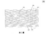
〔第3圖〕係本創作嵌入成型連接器之第一實施例沿複數條平行排列導體所構成平面之剖面圖。[Fig. 3] is a cross-sectional view of the first embodiment of the inventive insert molding connector along a plane formed by a plurality of parallel conductors.
〔第4圖〕係本創作嵌入成型連接器之第二實施例之立體圖。[Fig. 4] is a perspective view of the second embodiment of the insert-molded connector of the present invention.
〔第5圖〕係本創作嵌入成型連接器之第二實施例之俯視圖及沿A-A、B-B兩方向之剖面圖。[Fig. 5] is a top view and a cross-sectional view along the A-A and B-B directions of the second embodiment of the insert-molded connector of the present invention.
〔第6圖〕係本創作嵌入成型連接器之第二實施例沿複數條平行排列導體所構成平面之剖面圖。[Fig. 6] is the second embodiment of the insert-molded connector of the present invention, which is arranged along a plurality of parallel conductors.A cross-sectional view of a plane.
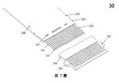
〔第7圖〕係本創作嵌入成型連接器之第三實施例之立體圖。[Fig. 7] is a perspective view of the third embodiment of the insert-molded connector of the present invention.
〔第8圖〕係本創作嵌入成型連接器之第三實施例之俯視圖及沿A-A、B-B兩方向之剖面圖。[Fig. 8] is a top view and a cross-sectional view along the A-A and B-B directions of the third embodiment of the insert-molded connector of the present invention.
〔第9圖〕係本創作嵌入成型連接器之第三實施例沿複數條平行排列導體所構成平面之剖面圖。[Fig. 9] is a cross-sectional view of the third embodiment of the insert molding connector of the present invention along a plane formed by a plurality of conductors arranged in parallel.
為能進一步瞭解本新型的特徵、技術手段以及所達成的具體功能、目的,列舉較具體的實施例,繼以圖式、圖號詳細說明如後。In order to further understand the features and technical means of the present invention, as well as the specific functions and purposes achieved, more specific embodiments are listed, followed by detailed descriptions with drawings and drawing numbers as follows.
以下各實施例的說明是參考附加的圖式,用以例示本創作可用以實施之特定實施例。本創作所提到的方向用語,例如「上」、「下」、「前」、「後」、「左」、「右」、「頂」、「底」、「水平」、「垂直」等,僅是參考附加圖式的方向。因此,使用的方向用語是用以說明及理解本創作,而非用以限制本創作。The following descriptions of the various embodiments refer to the accompanying drawings to illustrate specific embodiments in which the invention may be implemented. Directional terms mentioned in this creation, such as "up", "down", "front", "rear", "left", "right", "top", "bottom", "horizontal", "vertical", etc. , only refer to the orientation of the attached drawings. Therefore, the directional terms used are for explaining and understanding this creation, not for limiting this creation.
請參閱第1圖至第3圖。第1圖係本創作嵌入成型連接器之第一實施例10之立體圖。第2圖係本創作嵌入成型連接器之第一實施例10之俯視圖及沿A-A、B-B兩方向之剖面圖。第3圖係本創作嵌入成型連接器之第一實施例10沿複數條平行排列導體100所構成平面之剖面圖。本創作第一實施例之嵌入成型連接器10包括複數條平行排列之導線100、一包覆絕緣層200以及一連接器舌部300。複數條平行排列之導線100包括主要部101、傳輸接觸部102以及端部103。包覆絕緣層200包括固定通孔201、固定缺口202以及定位缺口203。連接器舌部300包括接觸開口301以及卡合部302。See Figures 1 to 3. FIG. 1 is a perspective view of the
複數條平行排列之導線100係用以傳輸電訊號。如包覆絕緣層200係用以包覆該些導線100之主要部101,並且露出些導線100之傳輸接觸部102。連接器舌部300係為嵌入成型所形成,同時包覆傳輸接觸部102與包覆絕緣層200靠近傳輸接觸部102之部分,並於接觸開口301露出傳輸接觸部102之接觸面。同時,該些導線100之端部103係不平行於傳輸接觸部102,例如如圖中所示向下彎折一定角度,以於連接器舌部300嵌入成型時,埋入連接器舌部300,用以強化該些導線100與連接器舌部300間之固定強度,但本創作並未以此為限定。A plurality of
再者於第一實施例中,如第2圖及第3圖所示,平行排列之導線100係為複數條扁平導體,亦即主要部101、傳輸接觸部102以及端部103為一體之扁平形狀導體。連接器舌部300之接觸開口301係用以露出傳輸接觸部102之接觸面,如圖中所示為傳輸接觸部102之上表面。再者,如第1圖至第3圖所示,包覆絕緣層200靠近傳輸接觸部102之部分包括至少一固定通孔201,使連接器舌部300嵌入成型於至少一固定通孔201中,於第一實施例中係設置複數個圓形之固定通孔201。如第1圖及第3圖所示,複數個圓形之固定通孔201等距地排列,並且固定通孔201均設置於平行排列之導線100之間,連接器舌部300嵌入成型時即填滿此些圓形之固定通孔201,用以強化包覆絕緣層200與連接器舌部300間之固定強度。Furthermore, in the first embodiment, as shown in FIG. 2 and FIG. 3 , the
如第1圖及第3圖所示,包覆絕緣層200之至少一固定缺口202係設置於靠近傳輸接觸部102之部分,使連接器舌部300嵌入成型於固定缺口202中,用以強化包覆絕緣層200與連接器舌部300間之固定強度。於第一實施例中,固定缺口202係設置於包覆絕緣層200靠近傳輸接觸部102部分之兩側,並且形狀係為矩形。再者,包覆絕緣層200之定位缺口203係設置於於包覆絕緣層200之兩側,係用於嵌入成型連接器10製作過程中,自動化設備作業定位之用。於第一實施例中,如第1圖及第2圖所示,連接器舌部300之接觸開口301係對應導線100之傳輸接觸部102設置,於連接器舌部300嵌入成型時,露出傳輸接觸部102之接觸面。如第1圖至第3圖所示,連接器舌部300之卡合部302係傳輸接觸部102之位於兩側,用以卡合、固定於設置於電路板上之板端連接器(未顯示)。As shown in FIG. 1 and FIG. 3 , at least one fixing
於第一實施例中,如第2圖所示,包覆絕緣層200係包括一上包覆膜層200-1與一下包覆膜層200-2。包覆絕緣層200之材料係選自聚酯、聚酰亞胺、聚乙烯、聚丙烯、聚四氟乙烯、丙烯酸或液晶高分子塑料,而嵌入成型之連接器舌部300之材料係選自聚酯、聚酰亞胺、聚乙烯、聚丙烯、聚四氟乙烯、丙烯酸或液晶高分子塑料。上包覆膜層200-1與下包覆膜層200-2係可以熱壓成型,如第1圖所示,自上下方包覆該些導線100之該主要部101,露出該些導線100之傳輸接觸部102。需特別說明的是,包覆絕緣層200之耐受溫度係高於連接器舌部300之嵌入成型製程溫度,亦即上包覆膜層200-1與下包覆膜層200-2之耐受溫度係高於連接器舌部300之嵌入成型製程溫度。是以,本創作方能藉由包覆絕緣層200之高溫耐受性,於後實施連接器舌部300之嵌入成型製程中,仍保持包覆絕緣層200原有之物理、化學及電學等相關特性。亦即連接器舌部300嵌入成型後,包覆絕緣層200原有之物理、化學及電學狀態均不會受嵌入成型之高溫影響,最終創造出構造極簡且可靠性高之嵌入成型連接器。In the first embodiment, as shown in FIG. 2, the cladding insulating
請參閱第4圖至第6圖。第4圖係本創作嵌入成型連接器之第二實施例20之立體圖。第5圖係本創作嵌入成型連接器之第二實施例20之俯視圖及沿A-A、B-B兩方向之剖面圖。第6圖係本創作嵌入成型連接器之第二實施例20沿複數條平行排列導體100所構成平面之剖面圖。本創作第二實施例之嵌入成型連接器20同樣地包括複數條平行排列之導線100、一包覆絕緣層200以及一連接器舌部300。複數條平行排列之導線100包括主要部101、傳輸接觸部102以及端部103。包覆絕緣層200包括固定通孔201、固定缺口202以及定位缺口203。連接器舌部300包括接觸開口301以及卡合部302。See Figures 4 to 6. Figure 4 is the first part of this creation of the insert molding connector.Two perspective views of Example 20. FIG. 5 is a top view and a cross-sectional view along the A-A and B-B directions of the
請參閱第4圖至第6圖。第二實施例之嵌入成型連接器20與第一實施例之嵌入成型連接器10不同之處在於,複數條平行排列之導線100之主要部101係為複數條圓形導體,複數條平行排列之導線100之傳輸接觸部102則原本係為主要部101同為圓形導體之延伸,經施予外力例如敲擊打扁而成為扁平導體。當然同樣地,端部103亦為扁平導體,其係為傳輸接觸部102前端經彎折後而形成。而第二實施例自動作業定位用之定位缺口203形狀可為圓形或半圓形等其它配適自動作業機台之形狀,本創作未有特別限定。See Figures 4 to 6. The difference between the insert-molded
請參閱第7圖至第9圖。第7圖係本創作嵌入成型連接器之第三實施例30之立體圖。第8圖係本創作嵌入成型連接器之第三實施例30之俯視圖及沿A-A、B-B兩方向之剖面圖。第9圖係本創作嵌入成型連接器之第三實施例30沿複數條平行排列導體100所構成平面之剖面圖。本創作第三實施例之嵌入成型連接器30同樣地包括複數條平行排列之導線100、一包覆絕緣層200以及一連接器舌部300。複數條平行排列之導線100包括主要部101、傳輸接觸部102以及端部103。包覆絕緣層200包括固定通孔201、固定缺口202以及定位缺口203。連接器舌部300包括接觸開口301以及卡合部302。See Figures 7 to 9. FIG. 7 is a perspective view of the
請參閱第7圖至第9圖。第三實施例之嵌入成型連接器30與第一實施例之嵌入成型連接器10不同之處在於,第一實施例中係設置複數個圓形之固定通孔201,而第三實施例中之固定通孔201係於包覆絕緣層200靠近傳輸接觸部102之部分設置複數個矩形之通孔。本創作對通孔之數量與長度未有特別限定,且可如第7圖至第9圖中所示曝露出包覆絕緣層200中之數條導線100之主要部101之部分。連接器舌部300嵌入成型後,更進一步增加連接器舌部300嵌入成型之強度。連接器舌部300嵌入成型時即填滿此些矩形之通孔201用以強化包覆絕緣層200與連接器舌部300間之固定強度。See Figures 7 to 9. The difference between the insert-molded
相較於現有習知之嵌入成型連接器,藉由包覆絕緣層200之高溫耐受性,而對其實施嵌入成型製程,而直接形成包覆且固持傳輸接觸部102與部分包覆絕緣層200之連接器舌部300,無需先對獨立存在之傳輸接觸部(傳輸端子)進行嵌入成型,先完成連接器舌部,再將傳輸接觸部(傳輸端子)焊接於具備包覆絕緣層之柔性扁平電纜之焊接部,是以創造出構造極簡且可靠性高之嵌入成型連接器。Compared with the conventional insert-molded connector, an insert-molding process is performed on the insulating-covering
雖然本創作已用較佳實施例揭露如上,然其並非用以限定本創作,任何熟習此技藝者,在不脫離本創作之精神和範圍內,當可作各種之更動與修改,因此本創作之保護範圍當視後附之申請專利範圍所界定者為准。Although this creation has been disclosed above with preferred embodiments, it is not intended to limit this creation. Anyone who is familiar with this technique can make various changes and modifications without departing from the spirit and scope of this creation. Therefore, this creation The scope of protection shall be determined by the scope of the appended patent application.
10:嵌入成型連接器10: Insert Molded Connectors
100:導線100: Wire
101:主要部101: Main Department
102:傳輸接觸部102: Transmission contact part
103:端部103: End
200:包覆絕緣層200: Clad insulating layer
200-1:上包覆膜層200-1: Upper cladding film
200-2:下包覆膜層200-2: Lower cladding film
203:定位缺口203: Positioning the gap
300:連接器舌部300: Connector tongue
301:接觸開口301: Contact opening
302:卡合部302: Engagement part
Claims (14)
Translated fromChinesePriority Applications (3)
| Application Number | Priority Date | Filing Date | Title |
|---|---|---|---|
| TW110213771UTWM627234U (en) | 2021-11-19 | 2021-11-19 | Insert molding connector |
| CN202222787286.5UCN218849852U (en) | 2021-11-19 | 2022-10-21 | Insert molding connector |
| US18/052,919US12334699B2 (en) | 2021-11-19 | 2022-11-06 | Insert molded connector |
Applications Claiming Priority (1)
| Application Number | Priority Date | Filing Date | Title |
|---|---|---|---|
| TW110213771UTWM627234U (en) | 2021-11-19 | 2021-11-19 | Insert molding connector |
Publications (1)
| Publication Number | Publication Date |
|---|---|
| TWM627234Utrue TWM627234U (en) | 2022-05-21 |
Family
ID=82559959
Family Applications (1)
| Application Number | Title | Priority Date | Filing Date |
|---|---|---|---|
| TW110213771UTWM627234U (en) | 2021-11-19 | 2021-11-19 | Insert molding connector |
Country Status (3)
| Country | Link |
|---|---|
| US (1) | US12334699B2 (en) |
| CN (1) | CN218849852U (en) |
| TW (1) | TWM627234U (en) |
Families Citing this family (1)
| Publication number | Priority date | Publication date | Assignee | Title |
|---|---|---|---|---|
| TWM627234U (en)* | 2021-11-19 | 2022-05-21 | 英豪科技股份有限公司 | Insert molding connector |
Family Cites Families (40)
| Publication number | Priority date | Publication date | Assignee | Title |
|---|---|---|---|---|
| JP2000348791A (en)* | 1999-06-01 | 2000-12-15 | Sumitomo Wiring Syst Ltd | Connection structure of flat cable to wire |
| AUPR399301A0 (en)* | 2001-03-27 | 2001-04-26 | Silverbrook Research Pty. Ltd. | An apparatus and method(ART106) |
| US8007286B1 (en)* | 2008-03-18 | 2011-08-30 | Metrospec Technology, Llc | Circuit boards interconnected by overlapping plated through holes portions |
| US8011950B2 (en)* | 2009-02-18 | 2011-09-06 | Cinch Connectors, Inc. | Electrical connector |
| TWM383782U (en)* | 2009-07-14 | 2010-07-01 | Ultrachip Inc | Resistance touch panel |
| CN201741902U (en)* | 2009-12-08 | 2011-02-09 | 富士康(昆山)电脑接插件有限公司 | Cable connector assembly |
| CN102148460B (en)* | 2010-02-08 | 2013-03-13 | 富士康(昆山)电脑接插件有限公司 | Cable connector component |
| CN102208726B (en)* | 2010-03-29 | 2013-05-08 | 富士康(昆山)电脑接插件有限公司 | Cable connector assembly |
| CN201708379U (en)* | 2010-04-07 | 2011-01-12 | 富士康(昆山)电脑接插件有限公司 | Cable Connector Assembly |
| JP5209038B2 (en)* | 2010-12-08 | 2013-06-12 | 日立オートモティブシステムズ株式会社 | Connector and manufacturing method thereof |
| JP2012182047A (en)* | 2011-03-02 | 2012-09-20 | Auto Network Gijutsu Kenkyusho:Kk | Bus-bar set and method for manufacturing the same |
| JP5611864B2 (en)* | 2011-03-09 | 2014-10-22 | アルプス電気株式会社 | Input device and method for manufacturing input device |
| US8235731B1 (en)* | 2011-03-18 | 2012-08-07 | Leviton Manufacturing Co., Ltd. | Connector module and patch panel |
| CN103050834B (en)* | 2011-10-12 | 2015-05-06 | 富士康(昆山)电脑接插件有限公司 | Cable connector assembly |
| JP5615795B2 (en)* | 2011-12-08 | 2014-10-29 | 第一精工株式会社 | Electrical connector |
| TWM430711U (en)* | 2012-02-16 | 2012-06-01 | Bing Xu Prec Co Ltd | Electrical connector assembly |
| TWM454650U (en)* | 2012-06-15 | 2013-06-01 | Bing Xu Prec Co Ltd | Card astragal cable connector assembly (2) |
| CN104737384B (en)* | 2012-10-18 | 2017-06-16 | 山一电机株式会社 | Socket connector, plug connector and possesses the electric connector of both |
| US20140206209A1 (en)* | 2013-01-24 | 2014-07-24 | Apple Inc. | Reversible usb connector |
| CN104183986B (en)* | 2013-05-24 | 2017-06-20 | 富士康(昆山)电脑接插件有限公司 | Plug connector |
| US9991622B2 (en)* | 2013-07-05 | 2018-06-05 | Asahi Kasei Chemicals Corporation | Electrical component comprising insulating resin molded article, and method for stabilizing flame retardance |
| CN104347973B (en)* | 2013-08-01 | 2016-09-28 | 富士康(昆山)电脑接插件有限公司 | Connector assembly |
| US9203193B2 (en)* | 2013-10-17 | 2015-12-01 | Tyco Electronics Corporation | Electrical device having a circuit board and a differential pair of signal conductors terminated thereto |
| US9640885B2 (en)* | 2013-11-17 | 2017-05-02 | Apple Inc. | Connector receptacle having a tongue |
| JP6119878B2 (en)* | 2014-01-09 | 2017-04-26 | 株式会社オートネットワーク技術研究所 | Wire with connector and method for manufacturing the same |
| US9017092B1 (en)* | 2014-05-07 | 2015-04-28 | Microsoft Technology Licensing, Llc | Electronic connector |
| US9166320B1 (en)* | 2014-06-25 | 2015-10-20 | Tyco Electronics Corporation | Cable connector assembly |
| US9437949B2 (en)* | 2014-09-26 | 2016-09-06 | Tyco Electronics Corporation | Electrical cable assembly configured to be mounted onto an array of electrical contacts |
| JP6406023B2 (en)* | 2015-01-15 | 2018-10-17 | 株式会社オートネットワーク技術研究所 | Electric wire, electric wire with terminal, and method for manufacturing electric wire with terminal |
| US10211552B2 (en)* | 2016-10-21 | 2019-02-19 | Foxconn Interconnect Technology Limited | Cable connector assembly having space-saving connection between cable wire conductors and contact terminating portions |
| CN206850124U (en)* | 2017-01-19 | 2018-01-05 | 番禺得意精密电子工业有限公司 | Electric connector and electric connector combination |
| TWM551363U (en)* | 2017-01-23 | 2017-11-01 | 宣德科技股份有限公司 | Improvement of the connector structure |
| CN207753259U (en)* | 2017-03-16 | 2018-08-21 | 立讯精密工业股份有限公司 | Plug and electric coupler component |
| JP2019003816A (en)* | 2017-06-14 | 2019-01-10 | 第一精工株式会社 | Electrical connector and manufacturing method thereof |
| JP7294329B2 (en)* | 2018-04-27 | 2023-06-20 | 住友電気工業株式会社 | connector and board |
| JP7262272B2 (en)* | 2019-03-28 | 2023-04-21 | 株式会社オートネットワーク技術研究所 | connector device |
| JP7324038B2 (en)* | 2019-04-23 | 2023-08-09 | モレックス エルエルシー | connector |
| TWM600493U (en)* | 2020-02-10 | 2020-08-21 | 品威電子國際股份有限公司 | Fixed structure of flexible flat wire electrical connector |
| JP7332652B2 (en)* | 2021-04-14 | 2023-08-23 | 矢崎総業株式会社 | connector |
| TWM627234U (en)* | 2021-11-19 | 2022-05-21 | 英豪科技股份有限公司 | Insert molding connector |
- 2021
- 2021-11-19TWTW110213771Upatent/TWM627234U/enunknown
- 2022
- 2022-10-21CNCN202222787286.5Upatent/CN218849852U/enactiveActive
- 2022-11-06USUS18/052,919patent/US12334699B2/enactiveActive
Also Published As
| Publication number | Publication date |
|---|---|
| US20230163547A1 (en) | 2023-05-25 |
| CN218849852U (en) | 2023-04-11 |
| US12334699B2 (en) | 2025-06-17 |
Similar Documents
| Publication | Publication Date | Title |
|---|---|---|
| TWI763825B (en) | Electrical device having a ground bus terminated to a cable drain wire | |
| US5598627A (en) | Method of making a wire harness | |
| US9203193B2 (en) | Electrical device having a circuit board and a differential pair of signal conductors terminated thereto | |
| US5663526A (en) | Optical module with tolerant wave soldered joints | |
| US5281765A (en) | Wiring assembly for equipment and a method for producing the same | |
| US7988465B2 (en) | Circuit board based connector with raised projection section | |
| US8242374B2 (en) | Flexible-circuit-board cable with positioning structure for insertion | |
| KR20100014064A (en) | Extremely thin coaxial wire harness, its connection method, wiring board connection body, wiring board module and electronic apparatus | |
| US10148052B2 (en) | Connecting-and-fixing method for cable | |
| CN103633460A (en) | Flexible circuit flat cable plug-in structure | |
| CN218849852U (en) | Insert molding connector | |
| US10498085B2 (en) | Molded interconnect substrate for a cable assembly | |
| KR20160121914A (en) | Flexible Bonding Structure including Flexible-Joints and FPCB | |
| WO2021159233A1 (en) | Adapter cable structure | |
| CN201927710U (en) | Coaxial wire guide structure | |
| JP2002359447A (en) | Connection structure for connecting flat cable and printed board | |
| CN101944671B (en) | Circuit cable with plug-in positioning structure | |
| CN201465618U (en) | Flexible cable and connecting structure thereof | |
| CN102005668B (en) | Circuit board plug positioning connector | |
| TWM600493U (en) | Fixed structure of flexible flat wire electrical connector | |
| CN113131264A (en) | Connecting assembly and manufacturing method thereof | |
| CN216773572U (en) | Wire end terminal, wire end connector cable, connector assembly, wire end connector and plate end connector | |
| KR101052160B1 (en) | Flat cable with multiple wiring layers | |
| CN218679473U (en) | Flexible circuit board and display device | |
| JP7740060B2 (en) | Connectors |