TWM622825U - Head mounted magnifying display device - Google Patents
Head mounted magnifying display deviceDownload PDFInfo
- Publication number
- TWM622825U TWM622825UTW110209156UTW110209156UTWM622825UTW M622825 UTWM622825 UTW M622825UTW 110209156 UTW110209156 UTW 110209156UTW 110209156 UTW110209156 UTW 110209156UTW M622825 UTWM622825 UTW M622825U
- Authority
- TW
- Taiwan
- Prior art keywords
- head
- module
- magnifying
- reflection
- sheet
- Prior art date
Links
- 210000003128headAnatomy0.000abstractdescription30
- 210000001508eyeAnatomy0.000abstractdescription11
- 230000003287optical effectEffects0.000abstractdescription10
- 230000003321amplificationEffects0.000abstractdescription4
- 238000003199nucleic acid amplification methodMethods0.000abstractdescription4
- 230000015572biosynthetic processEffects0.000abstractdescription3
- 230000004379myopiaEffects0.000description7
- 208000001491myopiaDiseases0.000description7
- 238000003384imaging methodMethods0.000description4
- 230000000694effectsEffects0.000description3
- 239000011248coating agentSubstances0.000description2
- 238000000576coating methodMethods0.000description2
- 239000013078crystalSubstances0.000description2
- 230000004438eyesightEffects0.000description2
- 230000007774longtermEffects0.000description2
- 230000000007visual effectEffects0.000description2
- 230000006978adaptationEffects0.000description1
- 230000005540biological transmissionEffects0.000description1
- 210000005252bulbus oculiAnatomy0.000description1
- 239000003814drugSubstances0.000description1
- 210000001061foreheadAnatomy0.000description1
- 230000002068genetic effectEffects0.000description1
- 238000000034methodMethods0.000description1
- 210000001525retinaAnatomy0.000description1
Images


Abstract
Translated fromChineseDescription
Translated fromChinese本新型係關於一種放大顯示裝置,特別係指一種頭戴式放大顯示裝置。The present invention relates to a magnifying display device, in particular to a head-mounted magnifying display device.
目前醫學已證明,近視的原因其中5%屬於遺傳因素,其他近視原因多屬長久近看導致,而長久近看的主要活動主要為看書、寫字,隨著文明的進步,近年看手機、平板及電腦的時間更是大幅增長,而人類近視就逐漸成為常態。At present, medicine has proved that 5% of the causes of myopia are genetic factors, and most of the other causes of myopia are caused by long-term near-sightedness. The main activities of long-term near-sightedness are mainly reading and writing. With the progress of civilization, in recent years, watching mobile phones and tablets The time spent on computers and computers has increased significantly, and human myopia has gradually become the norm.
通常,近視是眼球的長度增長所造成的結果,眼球由圓形變成了橢圓形。當看遠的景物時,水晶體已無法借著調適作用改變形狀,使影像無法正確投影在視網膜上。尤其兒童的水晶體尚在發育階段,其更容易因為用眼過度而改變形狀。從前述可之,如何限制看物之距離勿過於接近眼睛,儼然已成為現代人的重要課題。Usually, myopia is the result of an increase in the length of the eyeball, which changes from a round shape to an oval shape. When looking at a distant scene, the crystal cannot change its shape through adaptation, so that the image cannot be correctly projected on the retina. Especially children's crystals are still in the developing stage, and they are more likely to change shape due to overuse. From the above, how to limit the distance of seeing things so as not to get too close to the eyes has become an important issue for modern people.
請參閱中華民國公告號I677709,其揭示一種顯示裝置組件,其主要有一架體、一光學元件及一輔助件,並讓使用者能夠於架體上放置顯示單元(例如:手機),特別的是,該案中的光學元件配置於架體上,且位於顯示單元的影像光束的傳遞路徑上,由於光學元件是具有多層鍍膜的凹透鏡,藉此讓顯示單元所提供的影像光束傳遞至光學元件,並藉由光學元件上的多層鍍膜反射至使用者的眼睛中,以使得使用者可在觀察方向上對光學元件進行觀看,且在對光學元件進行觀看時獲得一虛擬影像,進而讓虛擬影像與真實世界所呈現的環境影像結合。Please refer to the Republic of China Announcement No. I677709, which discloses a display device assembly, which mainly includes a frame, an optical element and an auxiliary part, and enables a user to place a display unit (such as a mobile phone) on the frame, especially a , the optical element in this case is arranged on the frame and is located on the transmission path of the image beam of the display unit. Since the optical element is a concave lens with multi-layer coating, the image beam provided by the display unit is transmitted to the optical element, And through the multi-layer coating on the optical componentsProjecting into the user's eyes, so that the user can view the optical element in the observation direction, and obtain a virtual image when viewing the optical element, and then combine the virtual image with the environment image presented in the real world.
然而,該案中使用者所能看到的字體大小仍受限於於顯示單元(例如:手機)顯示的字體大小,雖然此能夠限制使用者與影像之間的距離,但仍難以解決使用者能夠看清字體的問題。有鑑於此,確有必要提供一技術手段,以解決現有問題。However, in this case, the font size that the user can see is still limited by the font size displayed by the display unit (eg, mobile phone). Although this can limit the distance between the user and the image, it is still difficult to solve the problem for the user. The problem of being able to see the font. In view of this, it is indeed necessary to provide a technical means to solve the existing problems.
本新型之目的在於,解決使用者觀看螢幕距離過近而造成近視的問題,同時須解決字體可能看不清的問題。The purpose of the present invention is to solve the problem of short-sightedness caused by the user viewing the screen too close, and at the same time to solve the problem that the font may not be clearly seen.
為達成前述目的,本新型為一種頭戴式放大顯示裝置,包含:一頭套,供以套設於人體頭部位置;一支臂組,連接該頭套,該支臂組具有一第一轉軸組;一反射模組,組設於該第一轉軸組上,且該反射模組具有為凸面鏡的一反射片,該反射片供以反射一投射影像;一放大模組,連接該支臂組,使該反射模組位於該放大模組及該人體頭部位置之間,且該放大模組具有為凹面鏡的一放大片,該放大片供以接收該投射影像放大後投射至人體眼睛位置。In order to achieve the aforementioned purpose, the present invention is a head-mounted magnifying display device, comprising: a head cover for fitting on the head of a human body; an arm set connected to the head cover, the arm set having a first rotating shaft group ; a reflection module set on the first rotating shaft group, and the reflection module has a reflection sheet that is a convex mirror, the reflection sheet is used to reflect a projected image; an amplification module is connected to the arm group, The reflection module is located between the amplifying module and the position of the head of the human body, and the amplifying module has a concave mirror amplifying sheet for receiving the projected image and then projecting it to the human eye position.
為達成前述目的,本新型另為一種頭戴式放大顯示裝置,包含:一頭套,供以套設於人體頭部位置;一支臂組,連接該頭套,該支臂組具有一第二轉軸組;一反射模組,連接該支臂組,並具有為凸面鏡的一反射片,該反射片供以反射一投射影像;一放大模組,設置於該第二轉軸組上,使該反射模組位於該放大模組及該人體頭部位置之間,且該放大模組具有為凹面鏡的一放大片,該放大片供以接收該投射影像在放大後投射至人體眼睛位置。In order to achieve the aforementioned purpose, the present invention is another head-mounted magnifying display device, comprising: a headgear for fitting on the head of a human body; an arm set connected to the headgear, the arm set having a second rotating shaft Group;A reflection module is connected to the arm group, and has a reflection sheet which is a convex mirror, and the reflection sheet is used for reflecting a projected image; a magnifying module is arranged on the second rotating shaft group, so that the reflection module is located in the Between the magnifying module and the position of the head of the human body, the magnifying module has a magnifying sheet which is a concave mirror, and the magnifying sheet is used to receive the projected image and project it to the position of the human eye after being enlarged.
為達成前述目的,本新型另為一種頭戴式放大顯示裝置,包含:一頭套,供以套設於人體頭部位置;一支臂組,連接該頭套,該支臂組具有一第一轉軸組及一第二轉軸組;一反射模組,設置於該第一轉軸組上,並具有為凸面鏡的一反射片,該反射片供以反射一投射影像;一放大模組,設置於該第二轉軸組上,使該反射模組位於該放大模組及該人體頭部位置之間,且該放大模組具有為凹面鏡的一放大片,該放大片供以接收該投射影像放大後投射至人體眼睛位置。In order to achieve the aforementioned object, the present invention is another head-mounted magnifying display device, comprising: a head cover for fitting on the head of a human body; an arm set connected to the head cover, and the arm set has a first rotating shaft group and a second shaft group; a reflection module set on the first shaft group, and has a reflection sheet which is a convex mirror, the reflection sheet is used for reflecting a projected image; a magnification module is arranged on the first rotation shaft group On the two rotating shaft sets, the reflection module is located between the amplifying module and the position of the head of the human body, and the amplifying module has a concave mirror with a magnifying piece for receiving the projected image and then projecting it to the Human eye position.
為達成前述目的,本新型另為一種頭戴式放大顯示裝置,包含:一頭套,供以套設於人體頭部位置;一支臂組,連接該頭套;一反射模組,連接該支臂組,並具有為凸面鏡的一反射片,該反射片供以反射一投射影像;一放大模組,連接該支臂組,使該反射模組位於該放大模組及該人體頭部位置之間,且該放大模組具有為凹面鏡的一放大片,該放大片供以接收該投射影像放大後投射至人體眼睛位置。In order to achieve the aforementioned purpose, the present invention is another head-mounted magnifying display device, comprising: a head cover for fitting on the head of a human body; an arm set connected to the head cover; a reflection module connected to the support arm A set of reflectors, which are convex mirrors, is used to reflect a projected image; a magnifying module is connected to the arm set, so that the reflecting module is located between the magnifying module and the position of the head of the human body , and the magnifying module has a magnifying sheet which is a concave mirror, and the magnifying sheet is used for receiving the projected image and then projecting it to the position of the human eye.
在一較佳實施例中,放大片的成像公式為
在一較佳實施例中,該頭套上分別設有一公魔鬼氈及一母魔鬼氈。In a preferred embodiment, a male devil felt and a female devil felt are respectively provided on the headgear.
在一較佳實施例中,該頭套上設有一扣環元件。In a preferred embodiment, the headgear is provided with a buckle element.
在一較佳實施例中,該頭套上設有一卡扣元件。In a preferred embodiment, the headgear is provided with a snap element.
所述之頭戴式放大顯示裝置,其中,該頭套具有弧形的一橫桿,以及分別連接該橫桿兩端並具有弧度的二側桿。In the head-mounted magnifying display device, the head cover has an arc-shaped horizontal bar, and two side bars respectively connected to both ends of the horizontal bar and having an arc.
使用者穿戴頭套後,其人體頭部位置的視覺前方將朝向該放大模組,而使用者的視覺前方的影像利用物理光學中,凹面鏡的虛像成項原理,使物體放大數倍並成像在比實際物距更遠,運用該光學技術以解決使用者長時間看近物的問題,不僅讓眼睛視覺看到的距離在一公尺以外,更讓物體放大以讓使用者得以視清。After the user wears the headgear, the visual front of the human head position will face the magnifying module, and the image in front of the user's vision uses the principle of virtual image formation of the concave mirror in physical optics, so that the object can be magnified several times and imaged in a larger ratio. The actual object distance is farther, and this optical technology is used to solve the problem of users looking at close objects for a long time. Not only can the eyes see the distance beyond one meter, but also the object can be enlarged so that the user can see clearly.
10:頭套10: headgear
11:橫桿11: Crossbar
12:側桿12: Sidebar
13:公魔鬼氈13: Male Devil Felt
14:母魔鬼氈14: Female Devil Felt
20:支臂組20: Arm set
21:第一轉軸組21: The first shaft group
22:第二轉軸組22: The second shaft group
30:反射模組30: Reflective module
31:反射片31: Reflector
40:放大模組40: Zoom Module
41:放大片41: Zoom in
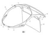
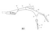
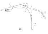
圖1為本新型於一較佳實施例中之立體圖;圖2為本新型於第一實施例中之側視分解圖;圖3為本新型於第二實施例中之側視分解圖;圖4為本新型於第三實施例中之側視分解圖;圖5為本新型於第四實施例中之側視分解圖。Fig. 1 is a perspective view of the novel in a preferred embodiment; Fig. 2 is an exploded side view of the novel in the first embodiment; Fig. 3 is an exploded side view of the novel in the second embodiment; 4 is an exploded side view of the novel in the third embodiment; FIG. 5 is a side exploded view of the novel in the fourth embodiment.
請參閱圖1及圖2,一種頭戴式放大顯示裝置,主要具有一頭套10、一支臂組20、一反射模組30及一放大模組40,其中:該頭套10供以套設於人體頭部位置;在本實施例中該頭套10具有弧形的一橫桿11,以及分別連接該橫桿11兩端並具有弧度的二側桿12,該橫桿11供以靠抵在人體頭部的額頭位置,而該二側桿12供以夾固在人體頭部的兩側位置。Please refer to FIG. 1 and FIG. 2 , a head-mounted magnifying display device mainly includes a
該支臂組20連接該頭套10;在本實施例中,該支臂組20呈U型並具有相對的兩端,兩端分別連接該橫桿11連接該二側桿12的位置,使該支臂組20朝向人體頭部位置前方延伸,該支臂組20具有一第一轉軸組21。The arm set 20 is connected to the
該反射模組30組設於該第一轉軸組21上,且該反射模組30具有為凸面鏡的一反射片31,該反射片31供以反射一投射影像;在本實施例中,該反射模組40朝向人體頭部的前方映照該投射影像。The
該放大模組40連接該支臂組20,使該反射模組30位於該放大模組40及該人體頭部位置之間,且該放大模組40具有為凹面鏡的一放大片41,該放大片41供以接收該投射影像在放大後投射至人體眼睛位置;在本實施例中,該放大片41的成像原理係透過凹面鏡之成像,而該放大片41的成像公式為:
(p:像距、q:物距、f:焦距)(p: image distance, q: object distance, f: focal length)
透過前述公式,不僅可以使該放大片41中的虛像放大,同時可以讓該虛像的距離更遠。Through the aforementioned formula, not only the virtual image in the
在本實施例中,該放大模組40的的角度固定,僅能夠透過該第一轉軸組31調整該反射模組30,以調節該虛像於該放大片41中成像的位置。In this embodiment, the angle of the
再者,該頭套10上分別設有一公魔鬼氈13及一母魔鬼氈14,如圖1所示,該頭套10係為一帶體,該頭套10兩端繞過該側桿12端部分設有公魔鬼氈13,中段處設有母魔鬼氈14,可與對應的公魔鬼氈13相互黏合或撕開以改變黏合位置以調整頭套10的尺寸,惟此調整頭套10尺寸的結構非為本案主要特徵,且仍有多種實施,亦可該公魔鬼氈13的其中一端固定連接於其中一個該側桿12,而該母魔鬼氈14的其中一端固定連接於另一個該側桿12,達到調整該頭套10的尺寸功能,亦可為該頭套10係為兩固定於該側桿12的帶體,一該帶體的另一端設置一扣環元件,供另一該帶體端部穿置成可調整定位的結構形態,或於兩帶體的端部分設有整排的凹孔及一凸扣的卡扣元件,以卡扣於不同凹孔,透過該扣環元件或該卡扣元件同樣能夠達成調整該頭套10尺寸的效果。Furthermore, the
請參閱圖3,在第二實施例中,該支臂組具有一第二轉軸組22,而在第二實施例中並無使用該第一轉軸組21,而該放大片41設置於該第二轉軸組22上,當該第二轉軸組22樞轉時可調整該放大片41的角度。Please refer to FIG. 3 , in the second embodiment, the arm assembly has a
請參閱圖4,在第三實施例中,該支臂組20具有一第一轉軸組21及一第二轉軸組22,該反射片21設置於該第一轉軸組21上,該放大片41設置於該第二轉軸組22上,藉此,讓該反射片31及該放大片41都能夠調整角度。Please refer to FIG. 4 , in the third embodiment, the arm set 20 has a first rotating shaft set 21 and a second rotating shaft set 22 , the
請參閱圖5,在第四實施例中並無使用該第一轉軸組21及該第二轉軸組22,該反射片31及該放大片41固定連接於該頭套10,使該反射片31及該放大片51都無法調整角度。Please refer to FIG. 5 , in the fourth embodiment, the first rotating
以上為本新型於各實施例中之結構組態及其連接關係,本新型之使用方法及其所能產生的效果如下所述:請參閱圖1,使用者穿戴頭套10後,其人體眼睛位置的視覺前方將朝向該放大模組50,而使用者的視覺前方的影像利用物理光學中,凹面鏡的虛像成項原理,使物體放大數倍並成像在比實際物距更遠,運用該光學技術以解決使用者長時間看近物的問題,不僅讓眼睛視覺看到的距離在一公尺以外,更讓物體放大以讓使用者得以視清。The above is the structural configuration and the connection relationship of the novel in each embodiment. The use method of the novel and the effects it can produce are as follows:Referring to FIG. 1 , after the user wears the
10:頭套10: headgear
11:橫桿11: Crossbar
12:側桿12: Sidebar
13:公魔鬼氈13: Male Devil Felt
14:母魔鬼氈14: Female Devil Felt
20:支臂組20: Arm set
21:第一轉軸組21: The first shaft group
30:反射模組30: Reflective module
40:放大模組40: Zoom Module
Claims (10)
Translated fromChinesePriority Applications (9)
| Application Number | Priority Date | Filing Date | Title |
|---|---|---|---|
| TW110209156UTWM622825U (en) | 2021-08-04 | 2021-08-04 | Head mounted magnifying display device |
| US17/574,510US12147055B2 (en) | 2021-08-04 | 2022-01-12 | Head-mounted fixing device |
| KR2020220000150UKR200498837Y1 (en) | 2021-08-04 | 2022-01-19 | Head-mounted fixing device |
| JP2022000123UJP3236793U (en) | 2021-08-04 | 2022-01-19 | Head mount mounting device |
| DE202022100374.2UDE202022100374U1 (en) | 2021-08-04 | 2022-01-24 | head fixation |
| AU2022203248AAU2022203248A1 (en) | 2021-08-04 | 2022-05-15 | Head-Mounted Fixing Device |
| GB2209683.8AGB2610280B (en) | 2021-08-04 | 2022-07-01 | Head-mounted fixing device and head-mounted display device |
| GB2311390.5AGB2618250B (en) | 2021-08-04 | 2022-07-01 | Head-mounted magnifying display device background |
| AU2023210653AAU2023210653B2 (en) | 2021-08-04 | 2023-08-04 | Head-Mounted Fixing Device |
Applications Claiming Priority (1)
| Application Number | Priority Date | Filing Date | Title |
|---|---|---|---|
| TW110209156UTWM622825U (en) | 2021-08-04 | 2021-08-04 | Head mounted magnifying display device |
Publications (1)
| Publication Number | Publication Date |
|---|---|
| TWM622825Utrue TWM622825U (en) | 2022-02-01 |
Family
ID=81323992
Family Applications (1)
| Application Number | Title | Priority Date | Filing Date |
|---|---|---|---|
| TW110209156UTWM622825U (en) | 2021-08-04 | 2021-08-04 | Head mounted magnifying display device |
Country Status (1)
| Country | Link |
|---|---|
| TW (1) | TWM622825U (en) |
- 2021
- 2021-08-04TWTW110209156Upatent/TWM622825U/enunknown
Similar Documents
| Publication | Publication Date | Title |
|---|---|---|
| US10120194B2 (en) | Wide field personal display | |
| JP5646238B2 (en) | Image display device | |
| JP4812181B2 (en) | Observation optical system, imaging optical system, and apparatus using the same | |
| JP4583569B2 (en) | Observation optical system and imaging optical system | |
| JP4727034B2 (en) | Observation optical system and imaging optical system | |
| JP4751534B2 (en) | Optical system and apparatus using the same | |
| US6310736B1 (en) | Image-forming optical system and viewing optical system | |
| US7969657B2 (en) | Imaging systems for eyeglass-based display devices | |
| WO2012032684A1 (en) | Optical prism assembly, and image display device and imaging device using optical prism assembly | |
| WO2016181459A1 (en) | Prism optical system, image display device using prism optical system, and imaging device using prism optical system | |
| CN109874302B (en) | Optical system, image magnifying device, virtual reality glasses and augmented reality glasses | |
| JP2012027350A (en) | Prism optical system, image display device using the prism optical system, and imaging apparatus using the prism optical system | |
| JP5576746B2 (en) | Decentered optical system, and image display device and imaging device using decentered optical system | |
| US12147055B2 (en) | Head-mounted fixing device | |
| JP4567163B2 (en) | Observation optical system and imaging optical system | |
| JP4751532B2 (en) | Optical system and apparatus using the same | |
| CN207833115U (en) | AR shows equipment | |
| JP4667655B2 (en) | Optical element and optical apparatus using the same | |
| JP2017134399A (en) | Glasses-free 3d display device without requiring interpupillary distance adjustment | |
| TWM622825U (en) | Head mounted magnifying display device | |
| WO2016150166A1 (en) | Amplification and display apparatus forming virtual image | |
| CN215494364U (en) | head mounted magnifying display device | |
| CN115903223A (en) | Head-mounted magnified display device | |
| JP4804644B2 (en) | Observation optical system, imaging optical system, and apparatus using the same | |
| JP4579396B2 (en) | Image display device |