TWM622202U - Head mounted fixing device - Google Patents
Head mounted fixing deviceDownload PDFInfo
- Publication number
- TWM622202U TWM622202UTW110210609UTW110210609UTWM622202UTW M622202 UTWM622202 UTW M622202UTW 110210609 UTW110210609 UTW 110210609UTW 110210609 UTW110210609 UTW 110210609UTW M622202 UTWM622202 UTW M622202U
- Authority
- TW
- Taiwan
- Prior art keywords
- head
- fixing device
- bracket
- headband
- front frame
- Prior art date
Links
- 210000003128headAnatomy0.000claimsabstractdescription56
- 210000001061foreheadAnatomy0.000claimsabstractdescription11
- 239000000463materialSubstances0.000claimsdescription3
- 230000008602contractionEffects0.000claimsdescription2
- 230000000007visual effectEffects0.000description4
- 238000010586diagramMethods0.000description3
- 208000001491myopiaDiseases0.000description3
- 230000004379myopiaEffects0.000description3
- 239000013013elastic materialSubstances0.000description2
- 238000005516engineering processMethods0.000description2
- 230000007774longtermEffects0.000description2
- 230000004075alterationEffects0.000description1
- 208000003464asthenopiaDiseases0.000description1
- 229940079593drugDrugs0.000description1
- 239000003814drugSubstances0.000description1
- 239000004744fabricSubstances0.000description1
- 238000012986modificationMethods0.000description1
- 230000004048modificationEffects0.000description1
Images


Classifications
- G—PHYSICS
- G02—OPTICS
- G02B—OPTICAL ELEMENTS, SYSTEMS OR APPARATUS
- G02B27/00—Optical systems or apparatus not provided for by any of the groups G02B1/00 - G02B26/00, G02B30/00
- G02B27/01—Head-up displays
- G02B27/017—Head mounted
- G02B27/0176—Head mounted characterised by mechanical features
- G—PHYSICS
- G02—OPTICS
- G02B—OPTICAL ELEMENTS, SYSTEMS OR APPARATUS
- G02B25/00—Eyepieces; Magnifying glasses
- G02B25/002—Magnifying glasses
- G02B25/005—Magnifying glasses with means for adjusting the magnifying glass or the object viewed
- G—PHYSICS
- G02—OPTICS
- G02C—SPECTACLES; SUNGLASSES OR GOGGLES INSOFAR AS THEY HAVE THE SAME FEATURES AS SPECTACLES; CONTACT LENSES
- G02C7/00—Optical parts
- G02C7/14—Mirrors; Prisms
- G—PHYSICS
- G02—OPTICS
- G02B—OPTICAL ELEMENTS, SYSTEMS OR APPARATUS
- G02B27/00—Optical systems or apparatus not provided for by any of the groups G02B1/00 - G02B26/00, G02B30/00
- G02B27/01—Head-up displays
- G02B27/0149—Head-up displays characterised by mechanical features
- G—PHYSICS
- G02—OPTICS
- G02B—OPTICAL ELEMENTS, SYSTEMS OR APPARATUS
- G02B27/00—Optical systems or apparatus not provided for by any of the groups G02B1/00 - G02B26/00, G02B30/00
- G02B27/01—Head-up displays
- G02B27/017—Head mounted
- G02B27/0172—Head mounted characterised by optical features
- G—PHYSICS
- G02—OPTICS
- G02B—OPTICAL ELEMENTS, SYSTEMS OR APPARATUS
- G02B7/00—Mountings, adjusting means, or light-tight connections, for optical elements
- G02B7/002—Mounting on the human body
- G—PHYSICS
- G02—OPTICS
- G02B—OPTICAL ELEMENTS, SYSTEMS OR APPARATUS
- G02B7/00—Mountings, adjusting means, or light-tight connections, for optical elements
- G02B7/18—Mountings, adjusting means, or light-tight connections, for optical elements for prisms; for mirrors
- G02B7/182—Mountings, adjusting means, or light-tight connections, for optical elements for prisms; for mirrors for mirrors
- G—PHYSICS
- G02—OPTICS
- G02C—SPECTACLES; SUNGLASSES OR GOGGLES INSOFAR AS THEY HAVE THE SAME FEATURES AS SPECTACLES; CONTACT LENSES
- G02C5/00—Constructions of non-optical parts
- G02C5/14—Side-members
- G—PHYSICS
- G02—OPTICS
- G02C—SPECTACLES; SUNGLASSES OR GOGGLES INSOFAR AS THEY HAVE THE SAME FEATURES AS SPECTACLES; CONTACT LENSES
- G02C5/00—Constructions of non-optical parts
- G02C5/22—Hinges
- G—PHYSICS
- G02—OPTICS
- G02B—OPTICAL ELEMENTS, SYSTEMS OR APPARATUS
- G02B5/00—Optical elements other than lenses
- G02B5/08—Mirrors
- G02B5/10—Mirrors with curved faces
- G—PHYSICS
- G02—OPTICS
- G02C—SPECTACLES; SUNGLASSES OR GOGGLES INSOFAR AS THEY HAVE THE SAME FEATURES AS SPECTACLES; CONTACT LENSES
- G02C3/00—Special supporting arrangements for lens assemblies or monocles
- G02C3/006—Arrangements for fitting and securing to the head or neck not in the position of use
Landscapes
- Physics & Mathematics (AREA)
- General Physics & Mathematics (AREA)
- Optics & Photonics (AREA)
- Health & Medical Sciences (AREA)
- Ophthalmology & Optometry (AREA)
- General Health & Medical Sciences (AREA)
- Headphones And Earphones (AREA)
- Helmets And Other Head Coverings (AREA)
Abstract
Translated fromChineseDescription
Translated fromChinese本創作涉及一種固定裝置,尤其是涉及一種頭戴式固定裝置。The present invention relates to a fixing device, in particular to a head-mounted fixing device.
醫學已證明長久近看是導致近視的主因。基本上,從物側至眼睛的視覺距離越長,對眼睛健康越有益。然而在閱讀、寫字或觀看行動電子裝置(例如手機、平板電腦)的螢幕時,視覺距離越長,視覺辨識能力反而越差,容易造成眼睛疲勞。因此,要能保持視覺辨識能力的情況下拉長視覺距離就需要仰賴新科技的輔助,例如將物側的虛像投射至人眼的技術,如專利TWM536362、CN102692710B、TWM550572、CN203608282U、TWI518369、CN203057249U、TWI563361、TW298625、TW201608279、CN201060318Y、TWM541404、TWM535811、TWM592084和TWM548275所揭示的,甚至可再搭配頭戴式固定裝置。Medicine has proven that long-term myopia is the main cause of myopia. Basically, the longer the visual distance from the object side to the eye, the better for eye health. However, when reading, writing or watching the screen of a mobile electronic device (such as a mobile phone and a tablet computer), the longer the visual distance, the worse the visual recognition ability, which is likely to cause eyestrain. Therefore, in order to maintain the visual recognition ability, it is necessary to rely on the assistance of new technologies, such as the technology of projecting the virtual image on the object side to the human eye, such as patents TWM536362, CN102692710B, TWM550572, CN203608282U, TWI518369, CN203057249U, TWI563361 , TW298625, TW201608279, CN201060318Y, TWM541404, TWM535811, TWM592084 and TWM548275, and can even be combined with a head-mounted fixture.
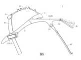
專利TWI654444(如圖1所示)和TWM536362揭露了一種頭戴式固定裝置。然而,這種固定裝置的設計有配戴不穩的問題。Patents TWI654444 (shown in Figure 1) and TWM536362 disclose a head-mounted fixture. However, the design of such a fixture suffers from an unstable fit.
因此,本創作的主要目的是提供一種可穩固配戴的頭戴式固定裝置。Therefore, the main purpose of the present invention is to provide a head-mounted fixture that can be worn securely.
為達上述目的,本創作一實施例所提供的一種頭戴式固定裝置,包含:一頭框,包含二側框部、位於該二側框部之間且連接該二側框部的一前框部以及分別設置於該二側框部的二第一調整件,該二側框部用以抵靠於一使用者的頭部的相對二側,該前框部用以抵靠於該使用者的額頭,該二側框部和該前框部為硬材質;一支架,該支架的一第一端連接該前框部,該支架用以抵靠該使用者的頭頂;以及一頭帶,連接該支架的一第二端,且可活動地連接該二第一調整件,該頭帶用以圍繞且抵靠該頭部的後方,該支架的該第二端相對於該第一端。該二側框部、該前框部、該支架和該頭帶抵靠該頭部,以限制該頭戴式固定裝置相對於該頭部移動;以及調整各該第一調整件在該頭帶的位置,以調整該前框部於該額頭上的位置。In order to achieve the above-mentioned purpose, an embodiment of the present invention provides a head-mounted fixing device, comprising: a head frame, including two side frame parts, located between the two side frame parts and connecting the two side framesA front frame part of the part and two first adjustment pieces respectively disposed on the two side frame parts, the two side frame parts are used to abut the opposite sides of a user's head, and the front frame part is used to abut leaning against the user's forehead, the two side frame parts and the front frame part are made of hard material; a bracket, a first end of the bracket is connected to the front frame part, and the bracket is used to abut the top of the user's head; and a headband connected to a second end of the bracket and movably connected to the two first adjustment pieces, the headband is used to surround and abut the rear of the head, the second end of the bracket is opposite to the first end. The two side frame parts, the front frame part, the bracket and the headband abut against the head, so as to limit the movement of the head-mounted fixing device relative to the head; and adjust each of the first adjustment members on the headband position to adjust the position of the front frame on the forehead.
在一些實施例中,該頭戴式固定裝置更包含:一延伸架,連接該頭框;一放大組件,連接該延伸架,且包含一放大片,該放大片面向該使用者;以及一反射組件,連接該延伸架,位於該放大組件和該使用者之間,且包含一反射片,該反射片背對該使用者,用以將來自一物側的物側光反射至該放大片,使該物側光經由該放大片放大後,被該放大片投射至該使用者的眼睛。In some embodiments, the head-mounted fixing device further includes: an extension frame connected to the head frame; a magnifying component connected to the extension frame and including a magnifying sheet facing the user; and a reflector an assembly, connected to the extension frame, located between the magnifying assembly and the user, and comprising a reflective sheet, the reflective sheet facing away from the user, for reflecting the object-side light from an object side to the magnifying sheet, After the object-side light is enlarged through the magnifying sheet, it is projected to the user's eyes by the magnifying sheet.
在一些實施例中,該反射片為一凸面鏡,該放大片為一凹面鏡。In some embodiments, the reflecting sheet is a convex mirror, and the magnifying sheet is a concave mirror.
在一些實施例中,該放大組件和該反射組件的至少其中之一是樞接於該延伸架,且該放大組件和該反射組件的該至少其中之一與該延伸架的各樞接處設有一第二轉軸。In some embodiments, at least one of the amplifying component and the reflecting component is pivotally connected to the extension frame, and the at least one of the amplifying component and the reflecting component is arranged at each pivotal connection of the extending frame There is a second reel.
在一些實施例中,該支架具有至少一可伸縮結構,藉由該支架的伸縮調整該頭戴式固定裝置相對於該頭部的貼合度。In some embodiments, the bracket has at least one retractable structure, and the fit of the head-mounted fixing device relative to the head can be adjusted by the expansion and contraction of the bracket.
在一些實施例中,該支架的該第一端是樞接於該前框部。In some embodiments, the first end of the bracket is pivotally connected to the front frame portion.
在一些實施例中,該前框部朝向該頭部的一表面設有一襯墊,該襯墊用以抵靠於該頭部。In some embodiments, a surface of the front frame portion facing the head is provided with a pad for abutting against the head.
在一些實施例中,該二側框部是樞接於該前框部,且該二側框部與該前框部的各樞接處設有一第一轉軸。In some embodiments, the two side frame portions are pivotally connected to the front frame portion, and each pivotal connection between the two side frame portions and the front frame portion is provided with a first rotating shaft.
在一些實施例中,該第一調整件為卡扣。In some embodiments, the first adjustment member is a buckle.
在一些實施例中,該頭帶設置有一第二調整件,該第二調整件用以調整該頭帶的長度。In some embodiments, the headband is provided with a second adjusting member for adjusting the length of the headband.
本創作所提供的頭戴式固定裝置可藉由頭框、支架和頭帶抵靠在使用者頭部,來限制頭戴式固定裝置相對於頭部移動,讓使用者可穩固地配戴頭戴式固定裝置。並且,頭框的前框部和位於前框部相對二側的二側框部可貼合頭部,使得頭戴式固定裝置配戴起來更穩固。The head-mounted fixing device provided by the present invention can limit the movement of the head-mounted fixing device relative to the head through the head frame, the bracket and the headband abutting on the user's head, so that the user can wear the head stably Wearable Fixtures. In addition, the front frame portion of the head frame and the two side frame portions located on opposite sides of the front frame portion can fit the head, so that the head-mounted fixing device can be worn more stably.
1:頭戴式固定裝置1: Head Mounted Fixtures
2:頭部2: head
10:頭框10: Head Frame
11:側框部11: Side frame
12:前框部12: Front frame
13:第一調整件13: The first adjustment piece
131:卡合蓋131: snap cover
132:卡合孔132: snap hole
133:穿孔133: Perforation
14:襯墊14: Padding
15:第一轉軸15: The first reel
20:支架20: Bracket
21:第一端21: First End
22:第二端22: Second End
23:可伸縮結構23: Scalable structure
24:穿孔24: Perforation
30:頭帶30: headband
31:端部31: End
32:第二調整件32: Second adjustment piece
33:第一接合元件33: First engaging element
34:第二接合元件34: Second engagement element
40:延伸架40: Extension rack
41:支臂41: Arm
G2,G3:第二轉軸G2, G3: the second axis
50:放大組件50: Amplify Components
51:支撐件51: Supports
52:放大片52: Zoom in
60:反射組件60: Reflective Components
61:支撐件61: Supports
62:反射片62: Reflector
在結合以下附圖研究了詳細描述之後,將發現本創作的其他方面及其優點:圖1為現有應用於頭戴式顯示裝置的頭戴式固定裝置的示意圖;圖2為根據本創作一實施例之頭戴式固定裝置的示意圖;圖3為根據本創作一實施例之頭戴式固定裝置的局部放大圖,用以呈現第一調整件的結構;圖4為根據本創作一實施例之頭戴式固定裝置的上視圖;圖5為根據本創作一實施例之頭戴式固定裝置的側視圖,用以呈現支架可彎曲;圖6為根據本創作一實施例之頭戴式固定裝置的局部放大圖,用以呈現頭帶上的一第二調整件的構成;圖7為根據本創作一實施例之頭戴式固定裝置的後視圖;圖8為根據本創作一實施例之使用者配戴頭戴式固定裝置的示意圖;以及圖9為根據本創作另一實施例之頭戴式固定裝置的側視圖,用以呈現放大組件可相對於延伸架樞轉。Other aspects and advantages of the present invention will be discovered after studying the detailed description in conjunction with the following drawings: FIG. 1 is a schematic diagram of an existing head-mounted fixture applied to a head-mounted display device; FIG. 2 is an implementation according to the present invention. The schematic diagram of the head-mounted fixing device of the present invention; FIG. 3 is a partial enlarged view of the head-mounted fixing device according to an embodiment of the present invention, which is used to show the structure of the first adjustment member; FIG. 4 is an embodiment of the present invention. The top view of the head-mounted fixture; FIG. 5 is a side view of the head-mounted fixture according to an embodiment of the present invention, for showing that the bracket can be bent;FIG. 6 is a partial enlarged view of the head-mounted fixing device according to an embodiment of the present invention, which is used to show the structure of a second adjustment member on the headband; FIG. 7 is a head-mounted fixing device according to an embodiment of the present invention. 8 is a schematic diagram of a user wearing a head-mounted fixture according to an embodiment of the present invention; and FIG. 9 is a side view of the head-mounted fixture according to another embodiment of the present invention, for presenting The magnifying assembly is pivotable relative to the extension frame.
請參考圖2至圖8所示,本創作一實施例所提供的頭戴式固定裝置1適於被配戴在使用者的頭部2。頭戴式固定裝置1包含一頭框10、一支架20、一頭帶30、一延伸架40、一放大組件50和一反射組件60。Referring to FIGS. 2 to 8 , the head-mounted
頭框10包含二側框部11、位於二側框部11之間的一前框部12以及分別設置於二側框部11的二第一調整件13。在本實施例中,二側框部11分別樞接於前框部12的相對二端。具體來說,二側框部11前端與前框部12的各樞接處可例如設有一第一轉軸15;然而,本創作不限於此樞接態樣。因此不使用時可折收該二側框部11。而在其他實施例中,二側框部11和前框部12也可以是一體成形。二側框部11用以抵靠於頭部2的相對二側,前框部12用以承靠於使用者的額頭。二側框部11和前框部12皆為硬材質,例如但不限於塑膠。第一調整件13可例如但不限於卡扣,如圖3所示,包含一卡合蓋131、一卡合孔132和二穿孔133。卡合蓋131可卡入一卡合孔132。二穿孔133可供頭帶30穿設。在本實施例或其他實施例中,前框部12朝向頭部2的一表面設有一襯墊14,襯墊14用以抵靠於額頭,以提升配戴的舒適度。The
支架20包含一第一端21、相對於第一端21的一第二端22以及位於第一端21和第二端22之間的至少一可伸縮結構23。支架20的第一端21樞接於前框部12。支架20的第二端22具有二開孔24,可供頭帶30穿設。可伸縮結構23可例如但不限於波浪結構且為彈性材質,因此可被拉長、壓縮和彎曲。The
頭帶30可例如但不限於為織物或彈性材料製成。頭帶30設置有一第二調整件32。第二調整件32可例如但不限於為魔鬼氈。以魔鬼氈的例子來說,第二調整件32可包含至少一第一接合元件33和至少一第二接合元件34,第一接合元件33可拆卸地接合第二接合元件34。在本實施例中,如圖6所示,第二調整件32包含分別設置在頭帶30的相對二端部31的二個第一接合元件33,以及包含位於相對二端部31之間的一個第二接合元件34,並且第一接合元件33和第二接合元件34皆位於頭帶30的同一表面上。然而,本創作並不限於上述範例。The
延伸架40連接頭框10,且由頭框10往遠離使用者的方向延伸。舉例來說,延伸架40包含二支臂41,且位於前框部12的相對二端。其中一支臂41的一端例如連接在前框部12的一端與一側框部11的交界處,另一支臂41的一端例如連接在前框部12的相對另一端與另一側框部11的交界處。然而,本創作並不限於上述的範例。並且,在本實施例中,前框部12和延伸架40是一體成形;在其他實施例中,延伸架40也可改為樞接前框部12。The
放大組件50包含一支撐件51(即第一支撐件)和一放大片52。支撐件51連接延伸架40的二支臂41的相對另一端。放大片52設置於支撐件51,且面向使用者。放大片52可例如但不限於為一凹面鏡。在本實施例中,延伸架40和支撐件51為一體成形;而在另一實施例中,支撐件51可改為樞接於二支臂41,如圖9所示,支撐件51與二支臂41的各樞接處設有一第二轉軸G2,使放大組件50的傾斜角度可調。然而,本創作不限於此樞接態樣The amplifying
反射組件60包含一支撐件61(即第二支撐件)和一反射片62。支撐件61樞接在延伸架40的二支臂41上的相對二位置,使得反射組件60位於放大組件50和使用者之間。具體來說,如圖2、8所示,支撐件61與各支臂41的樞接處設有一第二轉軸G3,使反射組件60的傾斜角度可調。然而,本創作不限於此樞接態樣。反射片62背對使用者。反射片62可例如但不限於為一凸面鏡。The
要配戴頭戴式固定裝置1時,可先將頭帶30的相對二端部31分別穿過頭框10的二第一調整件13的穿孔133,並讓頭帶30的相對二端部31分別穿過支架20的二穿孔24,如圖2至圖7所示。接著,如圖8所示,可讓前框部12抵靠在額頭,以提供一第一抵靠點;可讓二側框部11抵靠在頭部2的相對二側,以提供二第二抵靠點;可讓頭帶30圍繞並抵靠頭部2的後方,以提供一第三抵靠點;以及讓支架20彎曲並抵靠於頭頂,以提供一第四抵靠點。然後,可調整各側框部11相對於前框部12的角度,以調節頭框10服貼在頭部2的程度;可調整第一調整件13在頭帶30上的位置,以調整頭帶30抵靠在後腦勺上的位置和調整前框部12在額頭上的位置;以及可調整支架20的第二端22上的穿孔24在頭帶30上的位置,以調節支架20服貼在頭頂的程度。之後,可將各第一調整件13的卡合蓋131卡入對應的卡合孔132中,以限制第一調整件13相對於頭帶30移動;以及可將頭帶30上的各第一接合元件33接合於對應的第二接合元件34,以決定頭帶30在使用時的長度,並限制支架20的移動。如此一來,頭戴式固定裝置1與使用者的頭部2之間的第一至第四抵靠點便可限制頭戴式固定裝置1相對於頭部2移動而不晃動。When the head-mounted
當使用者配戴如圖9所示之頭戴式固定裝置1要進行閱讀、寫字或看行動電子裝置的螢幕時,可調整反射組件60相對於支臂41的角度或旋轉第二轉軸G3,以調整反射組件60的傾斜角度,使物側(即書本或行動電子裝置的螢幕)落入反射片62的入射範圍(即光線之入射角所涵蓋的範圍)內,並可調整放大組件50相對於支臂41的角度或旋轉第二轉軸G2,以調整放大組件50的傾斜角度,使放大片52落入反射片62的反射範圍(即光線之反射角所涵蓋的範圍)內。藉此,反射片62可將來自物側的物側光反射至放大片52。由於放大片52面向使用者,因此經由放大片52放大後的物側光會被放大片52投射至使用者的眼睛。此時,使用者便可透過放大片52看到書本或螢幕上的圖文,並且放大片52上之圖文的尺寸大於或等於此圖文在書本或螢幕上的尺寸。藉此,可減緩或避免長久近看對眼睛所造成的傷害。When the user wears the head-mounted
雖然本創作以前述之實施例揭露如上,然而這些實施例並非用以限定本創作。在不脫離本創作之精神和範圍內,所為之更動、潤飾與各實施態樣的組合,均屬本創作之專利保護範圍。關於本創作所界定之保護範圍請參考所附之申請專利範圍。Although the present invention is disclosed in the foregoing embodiments, these embodiments are not intended to limit the present invention. Without departing from the spirit and scope of this creation, the alterations, modifications and combinations of various implementation forms are all within the scope of patent protection of this creation. For the protection scope defined by this creation, please refer to the attached patent application scope.
1:頭戴式固定裝置1: Head Mounted Fixtures
10:頭框10: Head Frame
11:側框部11: Side frame
12:前框部12: Front frame
13:第一調整件13: The first adjustment piece
131:卡合蓋131: snap cover
20:支架20: Bracket
21:第一端21: First End
22:第二端22: Second End
23:可伸縮結構23: Scalable structure
30:頭帶30: headband
31:端部31: End
40:延伸架40: Extension rack
41:支臂41: Arm
50:放大組件50: Amplify Components
51:支撐件51: Supports
60:反射組件60: Reflective Components
61:支撐件61: Supports
62:反射片62: Reflector
G3:第二轉軸G3: The second shaft
Claims (10)
Translated fromChinesePriority Applications (7)
| Application Number | Priority Date | Filing Date | Title |
|---|---|---|---|
| TW110210609UTWM622202U (en) | 2021-09-08 | 2021-09-08 | Head mounted fixing device |
| CN202111220664.5ACN115774334A (en) | 2021-09-08 | 2021-10-20 | head mount |
| JP2021004047UJP3235606U (en) | 2021-09-08 | 2021-10-20 | Head mount fixing device |
| CN202122523986.9UCN216718815U (en) | 2021-09-08 | 2021-10-20 | Head-mounted fixing device |
| US17/451,929US11747631B2 (en) | 2021-09-08 | 2021-10-22 | Head-mounted fixing device |
| KR2020210003218UKR200498604Y1 (en) | 2021-09-08 | 2021-10-25 | Head-mounted fixing device |
| DE202021105816.1UDE202021105816U1 (en) | 2021-09-08 | 2021-10-25 | Head fixation |
Applications Claiming Priority (1)
| Application Number | Priority Date | Filing Date | Title |
|---|---|---|---|
| TW110210609UTWM622202U (en) | 2021-09-08 | 2021-09-08 | Head mounted fixing device |
Publications (1)
| Publication Number | Publication Date |
|---|---|
| TWM622202Utrue TWM622202U (en) | 2022-01-11 |
Family
ID=78822910
Family Applications (1)
| Application Number | Title | Priority Date | Filing Date |
|---|---|---|---|
| TW110210609UTWM622202U (en) | 2021-09-08 | 2021-09-08 | Head mounted fixing device |
Country Status (6)
| Country | Link |
|---|---|
| US (1) | US11747631B2 (en) |
| JP (1) | JP3235606U (en) |
| KR (1) | KR200498604Y1 (en) |
| CN (2) | CN115774334A (en) |
| DE (1) | DE202021105816U1 (en) |
| TW (1) | TWM622202U (en) |
Cited By (1)
| Publication number | Priority date | Publication date | Assignee | Title |
|---|---|---|---|---|
| GB2610280A (en)* | 2021-08-04 | 2023-03-01 | E Lead Electronic Co Ltd | Head-mounted fixing device and head-mounted display device |
Family Cites Families (22)
| Publication number | Priority date | Publication date | Assignee | Title |
|---|---|---|---|---|
| US5644430A (en) | 1995-03-16 | 1997-07-01 | Motorola | Single fold optical magnifier for use in image manifestation apparatus |
| JP3576985B2 (en)* | 2001-02-28 | 2004-10-13 | キヤノン株式会社 | Position adjustment mechanism and head mounted display device |
| CN201060318Y (en) | 2007-01-29 | 2008-05-14 | 王小光 | Video amplification composite shot |
| CN102692710B (en) | 2012-06-13 | 2014-10-01 | 北京大学人民医院 | A distance reading system for controlling the development of myopia in adolescents |
| CN203057249U (en) | 2013-02-02 | 2013-07-10 | 温万安 | Mobile phone screen amplifying device |
| CN203608282U (en) | 2013-12-23 | 2014-05-21 | 温万安 | Mobile phone screen amplification projector |
| TW201606350A (en) | 2014-08-12 | 2016-02-16 | Automotive Res & Testing Ct | Head-up display device |
| TWI621875B (en) | 2014-08-18 | 2018-04-21 | Young Optics Inc | Head up display system |
| TWI563361B (en) | 2014-12-26 | 2016-12-21 | Shinyoptics Corp | Virtual image display device for mobile apparatus |
| TWM535811U (en) | 2016-06-30 | 2017-01-21 | 葉天守 | Reflective virtual image displaying device |
| TWM536362U (en) | 2016-08-11 | 2017-02-01 | 葉天守 | Reflective enlarged virtual image display device |
| CN107817604A (en) | 2016-09-14 | 2018-03-20 | 上海蔚兰动力科技有限公司 | The adjustable reflector of new line display device and the new line display device for including it |
| TWM541404U (en) | 2016-12-27 | 2017-05-11 | E-Lead Electronic Co Ltd | Head-up display device with long distance image display |
| TWM550572U (en) | 2017-03-23 | 2017-10-21 | 聖母醫護管理專科學校 | Adjustable mirror with multi-function |
| JP7249941B2 (en)* | 2017-07-19 | 2023-03-31 | グリー株式会社 | head mounted display |
| CN109752848B (en) | 2017-11-06 | 2021-08-17 | 宏达国际电子股份有限公司 | head mounted display |
| CN208672914U (en)* | 2018-05-30 | 2019-03-29 | 广东未来科技有限公司 | A kind of naked eye three-dimensional virtual reality display helmet |
| GB2583777A (en)* | 2019-05-10 | 2020-11-11 | Astonishing Ltd | A virtual reality headset mount |
| US11561578B2 (en)* | 2019-09-17 | 2023-01-24 | Valve Corporation | Adjustable head-mounted display |
| TWM592084U (en) | 2019-10-16 | 2020-03-11 | 怡利電子工業股份有限公司 | Amplifying display device |
| KR102353037B1 (en)* | 2019-11-20 | 2022-01-19 | 김재근 | Augmented Reality Device Stationary Smart Phone |
| KR20210071600A (en) | 2019-12-06 | 2021-06-16 | 박홍석 | Leisure soft type head protector with gps |
- 2021
- 2021-09-08TWTW110210609Upatent/TWM622202U/enunknown
- 2021-10-20CNCN202111220664.5Apatent/CN115774334A/enactivePending
- 2021-10-20JPJP2021004047Upatent/JP3235606U/enactiveActive
- 2021-10-20CNCN202122523986.9Upatent/CN216718815U/enactiveActive
- 2021-10-22USUS17/451,929patent/US11747631B2/enactiveActive
- 2021-10-25DEDE202021105816.1Upatent/DE202021105816U1/enactiveActive
- 2021-10-25KRKR2020210003218Upatent/KR200498604Y1/enactiveActive
Cited By (2)
| Publication number | Priority date | Publication date | Assignee | Title |
|---|---|---|---|---|
| GB2610280A (en)* | 2021-08-04 | 2023-03-01 | E Lead Electronic Co Ltd | Head-mounted fixing device and head-mounted display device |
| GB2610280B (en)* | 2021-08-04 | 2023-11-08 | E Lead Electronic Co Ltd | Head-mounted fixing device and head-mounted display device |
Also Published As
| Publication number | Publication date |
|---|---|
| CN115774334A (en) | 2023-03-10 |
| KR200498604Y1 (en) | 2024-12-06 |
| KR20230000550U (en) | 2023-03-15 |
| US11747631B2 (en) | 2023-09-05 |
| DE202021105816U1 (en) | 2021-11-10 |
| JP3235606U (en) | 2022-01-06 |
| US20230071032A1 (en) | 2023-03-09 |
| CN216718815U (en) | 2022-06-10 |
Similar Documents
| Publication | Publication Date | Title |
|---|---|---|
| US10324295B2 (en) | Eyeglass-type display apparatus | |
| TWI657331B (en) | Head mounted display device | |
| AU2023210653B2 (en) | Head-Mounted Fixing Device | |
| KR20150094732A (en) | Spectacle with invisible optics | |
| WO2021043305A1 (en) | Face mask and head-mounted display apparatus | |
| JPWO2017221369A1 (en) | Wearable device | |
| WO2015109999A1 (en) | Optical vision converter | |
| TWM622202U (en) | Head mounted fixing device | |
| US20120038543A1 (en) | Method and Apparatus to Support Miniature Image Displays | |
| CN112083571A (en) | Head-mounted equipment support and head-mounted equipment | |
| CN112083575A (en) | Head-mounted display equipment support and intelligent near-to-eye display device | |
| JPH09159965A (en) | Head mount type video display device | |
| JP2020061679A (en) | Head mounted device | |
| JP4023412B2 (en) | Head-mounted image display device | |
| CN111133364B (en) | Dual-mode earphone | |
| TWM641937U (en) | Anti-shake magnification display device and anti-shake holder therefor | |
| CN215494364U (en) | head mounted magnifying display device | |
| TWM624513U (en) | Head Mounted Device | |
| CN216927267U (en) | Head-mounted fixing device | |
| WO2019129141A1 (en) | Head-mounted display | |
| CN115903223A (en) | Head-mounted magnified display device | |
| TWI614526B (en) | Head-mounted device with display image function (2) | |
| JP3109224B2 (en) | Glasses-type image display device | |
| JPH08168059A (en) | Head-mounted display device | |
| TWM622825U (en) | Head mounted magnifying display device |