TWM601313U - Modular building block type light bulb device - Google Patents
Modular building block type light bulb deviceDownload PDFInfo
- Publication number
- TWM601313U TWM601313UTW109205543UTW109205543UTWM601313UTW M601313 UTWM601313 UTW M601313UTW 109205543 UTW109205543 UTW 109205543UTW 109205543 UTW109205543 UTW 109205543UTW M601313 UTWM601313 UTW M601313U
- Authority
- TW
- Taiwan
- Prior art keywords
- assembly
- electrode
- shape feature
- building block
- substrate
- Prior art date
Links
- 239000000758substrateSubstances0.000claimsabstractdescription43
- 230000000712assemblyEffects0.000claimsabstractdescription18
- 238000000429assemblyMethods0.000claimsabstractdescription18
- 238000010586diagramMethods0.000description6
- 230000008878couplingEffects0.000description5
- 238000010168coupling processMethods0.000description5
- 238000005859coupling reactionMethods0.000description5
- 238000000034methodMethods0.000description5
- 230000002238attenuated effectEffects0.000description4
- 230000017525heat dissipationEffects0.000description4
- 239000000463materialSubstances0.000description4
- 230000008859changeEffects0.000description2
- 230000000694effectsEffects0.000description2
- 238000005516engineering processMethods0.000description2
- 239000002184metalSubstances0.000description2
- 239000008188pelletSubstances0.000description2
- 230000009286beneficial effectEffects0.000description1
- 238000005286illuminationMethods0.000description1
- 230000006872improvementEffects0.000description1
- 238000003780insertionMethods0.000description1
- 230000037431insertionEffects0.000description1
- 230000004060metabolic processEffects0.000description1
- 238000012986modificationMethods0.000description1
- 230000004048modificationEffects0.000description1
- 235000001968nicotinic acidNutrition0.000description1
- NJPPVKZQTLUDBO-UHFFFAOYSA-NnovaluronChemical compoundC1=C(Cl)C(OC(F)(F)C(OC(F)(F)F)F)=CC=C1NC(=O)NC(=O)C1=C(F)C=CC=C1FNJPPVKZQTLUDBO-UHFFFAOYSA-N0.000description1
- 235000015097nutrientsNutrition0.000description1
- 230000003287optical effectEffects0.000description1
- 230000008569processEffects0.000description1
- 239000002699waste materialSubstances0.000description1
Images


Landscapes
- Non-Portable Lighting Devices Or Systems Thereof (AREA)
- Arrangement Of Elements, Cooling, Sealing, Or The Like Of Lighting Devices (AREA)
Abstract
Translated fromChineseDescription
Translated fromChinese本新型是有關於一種燈泡裝置,尤其是一種可將光罩卸除並更換或調整LED(Light-emitting diode)的模組化積木式燈泡裝置。The present invention relates to a light bulb device, in particular to a modularized building block type light bulb device capable of removing the light shield and replacing or adjusting the LED (Light-emitting diode).
隨著科技的進步,LED(發光二極體,Light Emitting Diode)具有耗電低、體積小、壽命長及溫度低,等多項優點,尤其是在節能之優點上讓LED被廣泛使用。With the advancement of science and technology, LED (Light Emitting Diode) has many advantages such as low power consumption, small size, long life and low temperature, etc., especially for the advantages of energy saving, so that LEDs are widely used.
傳統白熾燈泡因耗電量大,溫度高,已經被其他燈具所取代,而LED是成為新一代的照明主流,並廣泛運用於各種照明燈具上,成為產業界中為達到省電以及環保要求而極力開發之新照明光源。Traditional incandescent bulbs have been replaced by other lamps due to their high power consumption and high temperature. LEDs have become the mainstream of a new generation of lighting, and are widely used in various lighting fixtures. Efforts to develop a new lighting source.
目前LED燈具的設計是呈封閉狀,LED燈粒被密封在光罩中,因此當LED損壞時,LED燈具就會被丟棄,造成其他可用材料的浪費及成本的提升。At present, the design of the LED lamp is closed, and the LED lamp pellet is sealed in the light cover. Therefore, when the LED is damaged, the LED lamp will be discarded, resulting in waste of other available materials and increased cost.
因此,目前LED燈具雖可符合一般使用者的需求,較為省電的方式進行照明,但是LED燈具損壞或衰減,就必須整組丟棄,無法發揮最大的效用,而尚有改進之空間。Therefore, although the current LED lamps can meet the needs of general users and use a more power-saving way to illuminate, but the LED lamps are damaged or attenuated, they must be discarded as a whole group, which cannot exert the maximum effect, and there is still room for improvement.
除此之外,目前市場亦有推出可調整亮度色溫的 LED 燈具,此類燈具的最大問題在於,調度光度的電路複雜且必須額外配置控制線路等缺點,其中,更必須在燈具開關上設置調光電路,額外在牆壁中進行控制線路的配置,此方式增加配線困難度以及安全上疑慮。In addition, LED lamps with adjustable brightness and color temperature are also available on the market. The biggest problem with this type of lamps is that the circuit for scheduling the luminosity is complicated and additional control circuits must be configured. Among them, the adjustment must be set on the lamp switch. Optical circuit, additional control circuit configuration in the wall, this method increases wiring difficulty and safety concerns.
雖然亦有業者提出以無線遙控器方式控制,此方法確實可以達到減少配線的目的,但需額外增加無線發射裝置,且燈具本身必需具有無線接收電路,導致燈具 的價格過高與使用不便等缺點。Although some companies have proposed to control with a wireless remote control, this method can indeed achieve the purpose of reducing wiring, but an additional wireless transmitting device is needed, and the lamp itself must have a wireless receiving circuit, resulting in high price and inconvenient use of the lamp. .
參閱圖1,為台灣專利M416721,一種可拆組式LED燈泡結構1,其包括包括一燈頭牙座101,可配一燈座102作不同規格設置,其外表設有螺牙103以螺合組設於該燈座102並取得導電關係,而在其內部則設有一容槽104,並在容槽104內端設有一對導電端子105,利用該容槽104可供另置的電源供應器106組設,並使一電源供應器106與導電端子105取得插組連結之導電關係。Refer to Figure 1, which is a Taiwan patent M416721, a detachable LED bulb structure 1, which includes a
該電源供應器106其主要功能係將交流電轉換為直流電,該電源供應器106的尺寸乃相符或略小於燈頭牙座101的容槽104,並在電源供應器106前、後兩端面分別置設有兩對插接孔107,其後端面插接孔107係供電源供應器106置入燈頭牙座101之容槽104時,得於槽內的導電端子105插結,而其前端面接插接孔107則可供電路基板108的電源插接線109插結,藉以取得對電路基板108的供電關係。The main function of the
一散熱飾座110係銜組於燈頭牙座101的前端,在散熱飾座110的前端設有一結合槽111以組設電路基板108,且在結合槽111槽底中心設有一對中空導管112,俾供電路基板108的電源插接線109得以通過中空導管112與燈頭牙座101內置的電源供應器106的插接孔107插結。又在散熱飾座110的結合槽111後端外周緣呈間隔狀地環設有多數之肋片113,且使其各相鄰肋片113間鏤設為散熱孔(圖式未示出),俾將內部的熱氣往外導排散發。A heat-dissipating
該電路基板108係組設於散熱飾座110的結合槽111內,其後部設有電源插接線109,俾使電源插接線109穿過散熱飾座110預設的中空導管112而插結於電源供應器106前端面的插接孔107內,取得電源供應器106對電路基板108的供電關係,而在電路基板108的前板面乃排列佈設有預定數目之LED燈114,以該等LED燈114發光作為照明光源。The
一透光燈罩115係結合於前述散熱飾座110前端的結合槽111,其採具透光性之材質製成,並可視需求製成球型或其他預定型態之罩體,用以對電路基板108及其LED燈114形成罩覆保護,並可使LED燈114的光線透過透光燈罩115向外透射。A light-transmitting
雖然習知技術揭露了一種以LED發光的燈具,但是實際使用時仍具有下列缺點:Although the prior art discloses a lamp that emits LED light, it still has the following shortcomings in actual use:
一、無法改變發光強度: 習知的電源固定,LED數量也固定,因此發出的光度固定,不能改變發光強度。1. The luminous intensity cannot be changed: The conventional power supply is fixed, and the number of LEDs is also fixed, so the luminosity emitted is fixed and the luminous intensity cannot be changed.
二、光罩無法卸除: 習知的光罩及基座固定,無法將光罩與基座上卸除。2. The mask cannot be removed: The conventional photomask and the base are fixed, and the photomask and the base cannot be removed.
三、無法更換LED: 習知的LED已焊接在電路板上,無法輕易地更換,當LED故障時,LED燈具就必須整組廢棄。3. LED cannot be replaced: The conventional LED has been soldered on the circuit board and cannot be easily replaced. When the LED fails, the entire set of LED lamps must be discarded.
因此,如何將LED燈粒與電路簡單組合及分離,以將故障的LED進行更換,更可以在不增加配線電路的條件下改變LED燈具的發光強度,是相關技術人員亟需努力的目標。Therefore, how to simply combine and separate the LED lamp pellets and the circuit to replace the faulty LED, and to change the luminous intensity of the LED lamp without increasing the wiring circuit, is an urgent goal for relevant technicians.
有鑑於此,本新型之目的是在提供一種模組化積木式燈泡裝置,包含一電源單元及至少一發光單元。In view of this, the purpose of the present invention is to provide a modularized building block type light bulb device, which includes a power supply unit and at least one light emitting unit.
該電源單元包括一基板、複數設置於該基板之第一組合件、複數設置於該基板之第二組合件及一設置於該基板之電源模組,該複數第一組合件分別具有一第一形狀特徵,該複數第二組合件分別具有一第二形狀特徵,該第一形狀特徵與該第二形狀特徵不同。The power supply unit includes a substrate, a plurality of first assemblies disposed on the substrate, a plurality of second assemblies disposed on the substrate, and a power module disposed on the substrate, the plurality of first assemblies respectively have a first The shape feature, each of the plurality of second assemblies has a second shape feature, and the first shape feature is different from the second shape feature.
該發光單元包括一座體、一設置於該座體之第三組合件、一設置於該座體之第四組合件及至少一設置於該座體之發光模組,該第三組合件可與該第一組合件組合,該第四組合件可與該第二組合件組合,以使該座體可分離地設置於該基板,並使該電源模組與該發光模組電連接。The light-emitting unit includes a base, a third assembly set on the base, a fourth assembly set on the base, and at least one light-emitting module set on the base. The third assembly can be combined with The first assembly is combined, and the fourth assembly can be combined with the second assembly, so that the base is detachably disposed on the substrate, and the power module is electrically connected to the light-emitting module.
本新型的又一技術手段,是在於上述之該第三組合件具有一第三形狀特徵,該第三形狀特徵與該第一形狀特徵相配合。Another technical means of the present invention is that the aforementioned third assembly has a third shape feature, and the third shape feature matches the first shape feature.
本新型的另一技術手段,是在於上述之該第四組合件具有一第四形狀特徵,該第四形狀特徵與該第二形狀特徵相配合。Another technical means of the present invention is that the above-mentioned fourth assembly has a fourth shape feature, and the fourth shape feature matches the second shape feature.
本新型的再一技術手段,是在於上述之該電源單元包括複數設置於該基板之第一電極及複數設置於該基板之第二電極。Another technical means of the present invention is that the above-mentioned power supply unit includes a plurality of first electrodes arranged on the substrate and a plurality of second electrodes arranged on the substrate.
本新型的又一技術手段,是在於上述之該發光單元更包括一設置於該座體之第三電極及一設置於該座體之第四電極,該第三電極可與該第一電極連接,該第四電極可與該第二電極連接。Another technical means of the present invention is that the above-mentioned light-emitting unit further includes a third electrode arranged on the base body and a fourth electrode arranged on the base body, and the third electrode can be connected to the first electrode , The fourth electrode can be connected to the second electrode.
本新型的另一技術手段,是在於上述之該第一電極設置於該第一組合件,該第二電極設置於該第二組合件,該第三電極設置於該第三組合件,該第四電極設置於該第四組合件。Another technical means of the present invention is that the above-mentioned first electrode is arranged in the first assembly, the second electrode is arranged in the second assembly, the third electrode is arranged in the third assembly, and the Four electrodes are arranged in the fourth assembly.
本新型的再一技術手段,是在於上述之模組化積木式燈泡裝置更包含一本體單元,該本體單元更包括一殼體,該基板設置於該殼體。Another technical means of the present invention is that the above-mentioned modularized building block light bulb device further includes a main body unit, and the main body unit further includes a casing, and the substrate is disposed on the casing.
本新型的又一技術手段,是在於上述之該本體單元更包括複數設置於該殼體之散熱片。Another technical means of the present invention is that the above-mentioned body unit further includes a plurality of heat sinks arranged on the casing.
本新型的另一技術手段,是在於上述之該本體單元更包括一設置於該殼體之頂垣。Another technical method of the present invention is that the above-mentioned body unit further includes a top wall disposed on the casing.
本新型的再一技術手段,是在於上述之該發光單元更包括一可分離地與該頂垣連接之光罩。Another technical method of the present invention is that the above-mentioned light-emitting unit further includes a photomask detachably connected to the top wall.
本新型之有益功效在於,。The beneficial effects of this new model are:
有關本新型之相關申請專利特色與技術內容,在以下配合參考圖式之兩個較佳實施例的詳細說明中,將可清楚地呈現。在進行詳細說明前應注意的是,類似的元件是以相同的編號來做表示。The characteristics and technical content of the patent application related to this new model will be clearly presented in the following detailed description of the two preferred embodiments with reference to the drawings. Before detailed description, it should be noted that similar components are represented by the same numbers.
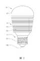
參閱圖2、圖3、圖4及圖5,為本新型一種模組化積木式燈泡裝置3之一第一較佳實施例,該模組化積木式燈泡裝置3包含一電源單元31、至少一發光單元32及一本體單元33。Refer to Figures 2, 3, 4 and 5, which are a first preferred embodiment of a new modularized building block type
該電源單元31包括一基板311、複數設置於該基板311之第一組合件312、複數設置於該基板311之第二組合件313、複數設置於該基板311之第一電極314、複數設置於該基板311之第二電極315及一設置於該座體321之電源模組316。於該第一較佳實施例,該複數第一電極314及該複數第二電極315設有三組,實際實施時,不應以此為限。The
該發光單元32包括一座體321、一設置於該座體321之第三組合件322、一設置於該座體321之第四組合件323、至少一設置於該座體321之發光模組324、一設置於該座體321之第三電極325、一設置於該座體321之第四電極326及一可分離地與該本體單元33連接之光罩327。於該第一較佳實施例,該座體321的數量為一至三個,實際實施時,不應以此為限。The
該本體單元33更包括一殼體331、複數設置於該殼體331之散熱片332、及一設置於該殼體331之頂垣333。該本體單元33之殼體331概呈圓柱形,該複數散熱片332設置在該殼體331外側並向外延伸。The
該殼體331的頂部具有一頂板334,該基板311設置於該殼體331之頂板334上,該頂板334設有孔洞,以提供該電源模組316穿過並置入該殼體331之中,該電源模組316產生的熱量可由該殼體331及該複數散熱片332進行散熱,該頂垣333設置於該頂板334的周緣,該光罩327可分離地與該頂垣333連接在一起。The top of the
該頂垣333可以支撐該光罩327,以使光罩327該座體321上不會脫落,較佳地,該頂垣333外側設有卡準,該光罩327的底緣內側設有對應卡準的溝槽,以使該光罩327與該頂垣333可分離地組合在一起。該光罩327為透光材料,以將該發光模組324所發出的光線對外透出。The
於該第一較佳實施例,該基板311為一種電路板,該電源模組316設置在該基板311的下表面,該第一組合件312、該第二組合件313、該第一電極314及該第二電極315設置在該基板311的上表面。該電源模組316透過基板311中的電路分別與該第一電極314及該第二電極315電連接。In the first preferred embodiment, the
該基板311中設有複數螺孔,可使用複數螺絲341將該基板311鎖設於該頂板334上。於該第一較佳實施例,該螺孔數量為三個,分別設置在每一組第一電極314及第二電極315之間,實際實施時,不應以此為限。The
該電源單元31更包括一設置於該座體321之第五電極317及一設置於該座體321之第六電極318,該第五電極317及該第六電極318與該電源模組316電連接,較佳地,該電源模組316底端設有二個接觸電極(如牆壁上的插座結構),以分別與該第五電極317及該第六電極318電連接,實際實施時,可使用其他電連接的結構,不應以此為限。The
該第五電極317及該第六電極318用以與市電(例如110V的交流電源)連接,該電源模組316是將市電進行變壓,以成為該發光模組324使用的電源(例如5V、12V,或24V等直流電源),並由該複數第一電極314及該複數第二電極315對外輸出。The
於該第一較佳實施例,該第五電極317及該第六電極318設置於該殼體331底部,較佳地,該第五電極317外表呈螺旋狀,該第六電極318與該第五電極317間隔,並設置在第五電極317下方,該第五電極317及該第六電極318的外觀與一般螺設的燈具相同,於此不再詳述,實際實施時,不應以此為限。In the first preferred embodiment, the
該複數第一組合件312分別具有一第一形狀特徵,該複數第二組合件313分別具有一第二形狀特徵,該第三組合件322具有一第三形狀特徵,該第三形狀特徵與該第一形狀特徵相配合,該第四組合件323具有一第四形狀特徵,該第四形狀特徵與該第二形狀特徵相配合,該第三組合件322可與該第一組合件312組合,該第四組合件323可與該第二組合件313組合。The plurality of
該第一形狀特徵與該第二形狀特徵不同,該第三形狀特徵與該第四形狀特徵不同,因此該第一組合件312無法與該第四組合件組合323,該第二組合件313無法與該第三組合件322組合,該。The first shape feature is different from the second shape feature, and the third shape feature is different from the fourth shape feature. Therefore, the
於該第一較佳實施例中,該第一形狀特徵為圓形柱體,該第二形狀特徵為四方形柱體,該第三形狀特徵為圓形凹槽,該第四形狀特徵為四方形凹槽,實際實施時,該第一形狀特徵、該第二形狀特徵、該第三形狀特徵及該第四形狀特徵可以為其他形狀的立體結構或凹槽結構,不應以此為限。In the first preferred embodiment, the first shape feature is a circular cylinder, the second shape feature is a square cylinder, the third shape feature is a circular groove, and the fourth shape feature is a quadrilateral For the square groove, in actual implementation, the first shape feature, the second shape feature, the third shape feature, and the fourth shape feature may be three-dimensional structures or groove structures of other shapes, and should not be limited thereto.
呈圓形柱體之第一形狀特徵的第一組合件312可與呈圓形凹槽之第三形狀特徵的第三組合件322組合,呈四方形柱體之第二形狀特徵第二組合件313可與呈四方形凹槽之第四形狀特徵的第四組合件323組合。The
進一步來說,呈圓形柱體之第一形狀特徵的第一組合件312無法與呈四方形凹槽之第四形狀特徵的第四組合件323組合,呈四方形柱體之第二形狀特徵第二組合件313無法與呈圓形凹槽之第三形狀特徵的第三組合件322組合。Furthermore, the
當該座體321上之第三組合件322及該第四組合件323分別與該基板311之第一組合件312及該第二組合件313組合時,該第三電極325可與該第一電極314連接,該第四電極326可與該第二電極315連接。該第三電極325及該第四電極326透過該座體321中的電路與該發光模組324電連接,以使該發光模組324對外發光。When the
該發光模組324為LED(發光二極體,Light Emitting Diode)燈粒,接收適當電壓的直流電時可對外發出光線。於該第一較佳實施例,每一座體321上設置二個發光模組324,實際實施時,不應以此為限。The
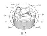
配合參閱圖6、圖7及圖8,分別為在該基板311上設置一個座體321、二個座體321或三個座體321的使用狀態,當該光罩327與該頂垣333分離後,可以調整該基板311上之座體321的數量,當設置一個座體321時,該模組化積木式燈泡裝置3發出的光線最弱,當設置三個座體321時,該模組化積木式燈泡裝置3發出的光線最強。因此本新型不需要另外設置複雜的控制電路就可以簡單的調整發光強度。除此之外,更可以將損壞或衰減之發光模組324的座體321更換,避免該電源模組316狀況良好卻將整個模組化積木式燈泡裝置3丟棄。With reference to Figures 6, 7 and 8, respectively, the use of a
因為本新型可以保留良好的電源模組316並繼續使用,有效符合搖籃到搖籃設計(Cradle-to-cradle design),C2C,cradle 2 cradle是產品及系統設計上仿生學的途徑,將人類的產業視為一種自然界的程序,將材料視為是在健康、安全的代謝中循環的養份。這個詞引用了另一個流行短語「從搖籃到墳墓」(Cradle to Grave)的概念,意思是搖籃到搖籃設計是可持續的,而且體現生命以及後代(一個是從一代的出生「搖籃」到下一代的出生,另一個則是從一代的出生到同一代的死亡)。Because the new model can keep
因為該座體321之第三組合件322只可以與該第一組合件312組合,該第四組合件323只可以與該第二組合件313組合,可以避免該座體321於該基板311上的方向設置錯誤,令該第一電極314與該第三電極325電連接,該第二電極315與該第四電極326電連接,避免該發光模組324因為連接電源方向不正確而發生不發光的狀況。Because the
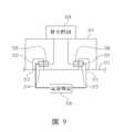
配合參閱圖9,為本新型一種模組化積木式燈泡裝置3之一第二較佳實施例,該第二較佳實施例與該第一較佳實施例大致相同,相同之處於此不再詳述,不同之處在於,該第一電極314設置於該第一組合件312,該第二電極315設置於該第二組合件313,該第三電極325設置於該第三組合件322,該第四電極326設置於該第四組合件323。With reference to FIG. 9, it is a second preferred embodiment of a new modularized building block
於該第二較佳實施例,該第一電極314為該第一組合件312且外觀呈圓形柱體,該第二電極315為該第二組合件313且外觀呈四方形柱體,該第三電極325為該第三組合件322且外型呈圓形凹槽,該第四電極326為該第四組合件323且外觀呈四方形凹槽。實際實施時,該第一電極314可以是包覆於該第一組合件312表面的導電層,該第二電極315可以是包覆於該第二組合件313表面的導電層,該第三電極325可以是設置於該第三組合件322中並具有彈性的金屬板件,該第四電極326可以是設置於該第四組合件323中並具有彈性的金屬板件(類似一般充電插座及充電插孔,只是插座及插孔形狀有所差異),或是使用其他的導電技術做為該第一電極314、該第二電極315、該第三電極325、該第四電極326的結構,不應以本較佳實施例之舉例為限。In the second preferred embodiment, the
於該第二較佳實施例中,因為該第一組合件312只能與該第三組合件322組合,該第二組合件313只能與該第四組合件323組合,因此該第一電極314只會跟該第三電極325電連接,不會與第四電極326連接,且該第二電極315只會跟該第四電極326電連接,不會與第三電極325連接。In the second preferred embodiment, because the
由上述說明可知,本新型一種模組化積木式燈泡裝置3確實具有下列功效:It can be seen from the above description that the new modularized building block type
一、簡單改變光度: 該基板311上設置有複數組第一組合件312及複數第二組合件313,可以將不同數量的座體321設置於該基板311上,該座體321數量越少發光強度越弱,該座體321數量越多發光強度越強。1. Simply change the luminosity: The
二、可以卸除光罩327: 該光罩327可分離地與該頂垣333組合在一起,有別早期密封式光罩327設置,本新型之模組化積木式燈泡裝置3可以清楚的看見發光模組324。2. The
三、減少成本: 續上所述,因為該光罩327可與該頂垣333分離,因此可以將損壞或衰減的發光模組324進行更換,以使未損壞的電源模組316繼續使用,有效減少成本。3. Reduce costs: As described above, because the
綜上所述,本新型將該座體321模組化,並設計成類似積木組合的結構,透過該第三組合件322及該第四組合件323與該基板311組合,不僅可以調整發光強度,更可以將損壞或衰減的發光模組324進行更換,避免將未損壞的電源模組316丟棄,故確實可以達成本新型之目的。To sum up, the present invention modularizes the
惟以上所述者,僅為本新型之兩個較佳實施例而已,當不能以此限定本新型實施之範圍,即大凡依本新型申請專利範圍及新型說明內容所作之簡單的等效變化與修飾,皆仍屬本新型專利涵蓋之範圍內。However, the above-mentioned are only two preferred embodiments of the present model, and should not be used to limit the scope of implementation of the present model, that is, simple equivalent changes and changes made in accordance with the scope of the patent application and the description of the model Modifications are still within the scope of this new patent.
1:可拆組式LED燈泡結構 101:燈頭牙座 102:燈座 103:螺牙 104:容槽 105:導電端子 106:電源供應器 107:插接孔 108:電路基板 109:電源插接線 110:散熱飾座 111:結合槽 112:中空導管 113:肋片 114:LED燈 115:透光燈罩 3:模組化積木式燈泡裝置 31:電源單元 311:基板 312:第一組合件 313:第二組合件 314:第一電極 315:第二電極 316:電源模組 317:第五電極 318:第六電極 32:發光單元 321:座體 322:第三組合件 323:第四組合件 324:發光模組 325:第三電極 326:第四電極 327:光罩 33:本體單元 331:殼體 332:散熱片 333:頂垣 334:頂板 341:螺絲1: Detachable LED bulb structure 101: Lamp holder tooth holder 102: Lamp holder 103: Thread 104: container 105: conductive terminal 106: power supply 107: Socket hole 108: Circuit board 109: Power cord 110: heat sink 111: Combination Slot 112: Hollow catheter 113: Rib 114: LED light 115: Translucent lampshade 3: Modular building block type light bulb device 31: power supply unit 311: substrate 312: The first assembly 313: second assembly 314: first electrode 315: second electrode 316: Power Module 317: Fifth electrode 318: sixth electrode 32: light-emitting unit 321: Block 322: The third assembly 323: The fourth assembly 324: Light-emitting module 325: third electrode 326: fourth electrode 327: Mask 33: body unit 331: Shell 332: heat sink 333: Top Wall 334: top plate 341: Screw
圖1是一剖面示意圖,說明中華民國專利M416721,一種可拆組式LED燈泡結構; 圖2是一立體示意圖,為本新型一種模組化積木式燈泡裝置之一第一較佳實施例,說明該模組化積木式燈泡裝置的立體態樣; 圖3是一側視示意圖,說明於該第一較佳實施例中,該模組化積木式燈泡裝置的側視態樣; 圖4是一分解示意圖,說明於該第一較佳實施例中,該模組化積木式燈泡裝置的分解態樣; 圖5是一立體示意圖,說明於該第一較佳實施例中,一座體的立體態樣; 圖6是一使用示意圖,說明於該第一較佳實施例中,一基板上設置一座體的使用態樣; 圖7是一使用示意圖,說明於該第一較佳實施例中,一基板上設置二座體的使用態樣; 圖8是一使用示意圖,說明於該第一較佳實施例中,一基板上設置三座體的使用態樣;及 圖9是一剖面示意圖,為本新型一種模組化積木式燈泡裝置之一第二較佳實施例,說明一發光單元與一電源單元組合的剖面態樣。Figure 1 is a schematic cross-sectional view illustrating the Republic of China patent M416721, a detachable LED bulb structure; Figure 2 is a three-dimensional schematic diagram showing a first preferred embodiment of a new modularized building block type light bulb device, illustrating the three-dimensional aspect of the modularized building block type light bulb device; 3 is a schematic side view illustrating the side view of the modularized building block light bulb device in the first preferred embodiment; 4 is an exploded schematic diagram illustrating the exploded state of the modularized building block type light bulb device in the first preferred embodiment; Figure 5 is a three-dimensional schematic diagram illustrating the three-dimensional configuration of the base in the first preferred embodiment; Fig. 6 is a schematic diagram illustrating the use of a base body on a substrate in the first preferred embodiment; Figure 7 is a schematic diagram illustrating the use of two bases on a substrate in the first preferred embodiment; FIG. 8 is a schematic diagram illustrating the use of three bases on a substrate in the first preferred embodiment; and 9 is a schematic cross-sectional view showing a second preferred embodiment of a new modularized building block type light bulb device, illustrating a cross-sectional view of a combination of a light-emitting unit and a power supply unit.
311:基板311: substrate
312:第一組合件312: The first assembly
313:第二組合件313: second assembly
314:第一電極314: first electrode
315:第二電極315: second electrode
316:電源模組316: Power Module
317:第五電極317: Fifth electrode
321:座體321: Block
324:發光模組324: Light-emitting module
327:光罩327: Mask
332:散熱片332: heat sink
333:頂垣333: Top Wall
334:頂板334: top plate
341:螺絲341: Screw
Claims (10)
Translated fromChinesePriority Applications (1)
| Application Number | Priority Date | Filing Date | Title |
|---|---|---|---|
| TW109205543UTWM601313U (en) | 2020-05-08 | 2020-05-08 | Modular building block type light bulb device |
Applications Claiming Priority (1)
| Application Number | Priority Date | Filing Date | Title |
|---|---|---|---|
| TW109205543UTWM601313U (en) | 2020-05-08 | 2020-05-08 | Modular building block type light bulb device |
Publications (1)
| Publication Number | Publication Date |
|---|---|
| TWM601313Utrue TWM601313U (en) | 2020-09-11 |
Family
ID=73645091
Family Applications (1)
| Application Number | Title | Priority Date | Filing Date |
|---|---|---|---|
| TW109205543UTWM601313U (en) | 2020-05-08 | 2020-05-08 | Modular building block type light bulb device |
Country Status (1)
| Country | Link |
|---|---|
| TW (1) | TWM601313U (en) |
Cited By (1)
| Publication number | Priority date | Publication date | Assignee | Title |
|---|---|---|---|---|
| TWI759919B (en)* | 2020-10-21 | 2022-04-01 | 林孝正 | Light-emitting device and bulb with the same |
- 2020
- 2020-05-08TWTW109205543Upatent/TWM601313U/ennot_activeIP Right Cessation
Cited By (1)
| Publication number | Priority date | Publication date | Assignee | Title |
|---|---|---|---|---|
| TWI759919B (en)* | 2020-10-21 | 2022-04-01 | 林孝正 | Light-emitting device and bulb with the same |
Similar Documents
| Publication | Publication Date | Title |
|---|---|---|
| US7976211B2 (en) | Light bulb utilizing a replaceable LED light source | |
| ES2984108T3 (en) | Lighting device | |
| US8201985B2 (en) | Light bulb utilizing a replaceable LED light source | |
| US20120257374A1 (en) | Led lamp | |
| US20130279164A1 (en) | Led lighting fixtures | |
| US20090273940A1 (en) | LED lighting device | |
| TWI405932B (en) | Led lamp | |
| WO2013040877A1 (en) | Led floodlight | |
| TWM449908U (en) | Structure for LED (light emitting diode) lamp | |
| US20120043876A1 (en) | Two Confronting Planar LED Lamps with Shades | |
| TWM601313U (en) | Modular building block type light bulb device | |
| CN202040604U (en) | flashlight | |
| TWI721882B (en) | Light emitting device | |
| CN201116702Y (en) | LED lighting unit and light source module thereof | |
| CN201277453Y (en) | Lamp holder module of lamp | |
| CN201155668Y (en) | Combined structure of lamp | |
| WO2019109467A1 (en) | Anti-glare lamp having modularized led light source | |
| CN101813243B (en) | LED illumination lamp | |
| KR101162846B1 (en) | muli-typed LED lamp | |
| CN206555743U (en) | A kind of LED spotlights | |
| CN204494133U (en) | The LED lamp of a kind of integrated LED light source and composition thereof | |
| CN216769142U (en) | Lamp holder and desk lamp with same | |
| CN202915069U (en) | Illumination structure of all-round LED lamp | |
| CN108870118A (en) | A kind of combined LED lamp tube | |
| CN201269422Y (en) | Combined light-emitting diode module and lamp thereof |
Legal Events
| Date | Code | Title | Description |
|---|---|---|---|
| MM4K | Annulment or lapse of a utility model due to non-payment of fees |