TWM597506U - Chemical vapor deposition apparatus with multi-zone injector block - Google Patents
Chemical vapor deposition apparatus with multi-zone injector blockDownload PDFInfo
- Publication number
- TWM597506U TWM597506UTW108204554UTW108204554UTWM597506UTW M597506 UTWM597506 UTW M597506UTW 108204554 UTW108204554 UTW 108204554UTW 108204554 UTW108204554 UTW 108204554UTW M597506 UTWM597506 UTW M597506U
- Authority
- TW
- Taiwan
- Prior art keywords
- reaction gas
- region
- gas
- reaction
- supplied
- Prior art date
Links
- 238000005229chemical vapour depositionMethods0.000titleclaimsabstractdescription32
- 238000009826distributionMethods0.000claimsabstractdescription126
- 239000007789gasSubstances0.000claimsabstractdescription117
- 239000000376reactantSubstances0.000claimsabstractdescription28
- 239000012495reaction gasSubstances0.000claimsdescription300
- 238000012545processingMethods0.000claimsdescription46
- 238000006243chemical reactionMethods0.000claimsdescription9
- 239000000758substrateSubstances0.000claimsdescription5
- 235000012431wafersNutrition0.000description75
- 238000000034methodMethods0.000description36
- 230000008569processEffects0.000description33
- 239000012159carrier gasSubstances0.000description14
- 125000000217alkyl groupChemical group0.000description10
- 229910052751metalInorganic materials0.000description10
- 239000002184metalSubstances0.000description10
- 239000004065semiconductorSubstances0.000description10
- 150000004678hydridesChemical class0.000description9
- 239000002826coolantSubstances0.000description8
- 238000010438heat treatmentMethods0.000description8
- 238000004519manufacturing processMethods0.000description8
- 238000000197pyrolysisMethods0.000description8
- 239000000463materialSubstances0.000description7
- 239000000203mixtureSubstances0.000description5
- 230000006872improvementEffects0.000description4
- 230000007246mechanismEffects0.000description4
- 238000005192partitionMethods0.000description4
- 238000004891communicationMethods0.000description3
- 238000000151depositionMethods0.000description3
- 239000012530fluidSubstances0.000description3
- 238000012546transferMethods0.000description3
- 238000011144upstream manufacturingMethods0.000description3
- VYPSYNLAJGMNEJ-UHFFFAOYSA-NSilicium dioxideChemical compoundO=[Si]=OVYPSYNLAJGMNEJ-UHFFFAOYSA-N0.000description2
- 238000013459approachMethods0.000description2
- 150000001875compoundsChemical class0.000description2
- 230000005494condensationEffects0.000description2
- 238000009833condensationMethods0.000description2
- 239000012809cooling fluidSubstances0.000description2
- 239000013078crystalSubstances0.000description2
- 230000008021depositionEffects0.000description2
- 238000010586diagramMethods0.000description2
- 229910052733galliumInorganic materials0.000description2
- 230000005484gravityEffects0.000description2
- 229910021478group 5 elementInorganic materials0.000description2
- 229910052738indiumInorganic materials0.000description2
- 230000003993interactionEffects0.000description2
- 150000002739metalsChemical class0.000description2
- 230000002093peripheral effectEffects0.000description2
- 238000010944pre-mature reactionyMethods0.000description2
- PIGFYZPCRLYGLF-UHFFFAOYSA-NAluminum nitrideChemical compound[Al]#NPIGFYZPCRLYGLF-UHFFFAOYSA-N0.000description1
- JBRZTFJDHDCESZ-UHFFFAOYSA-NAsGaChemical compound[As]#[Ga]JBRZTFJDHDCESZ-UHFFFAOYSA-N0.000description1
- VEXZGXHMUGYJMC-UHFFFAOYSA-MChloride anionChemical compound[Cl-]VEXZGXHMUGYJMC-UHFFFAOYSA-M0.000description1
- GYHNNYVSQQEPJS-UHFFFAOYSA-NGalliumChemical compound[Ga]GYHNNYVSQQEPJS-UHFFFAOYSA-N0.000description1
- GPXJNWSHGFTCBW-UHFFFAOYSA-NIndium phosphideChemical compound[In]#PGPXJNWSHGFTCBW-UHFFFAOYSA-N0.000description1
- 229910004298SiO 2Inorganic materials0.000description1
- XUIMIQQOPSSXEZ-UHFFFAOYSA-NSiliconChemical compound[Si]XUIMIQQOPSSXEZ-UHFFFAOYSA-N0.000description1
- 229910052782aluminiumInorganic materials0.000description1
- XAGFODPZIPBFFR-UHFFFAOYSA-NaluminiumChemical compound[Al]XAGFODPZIPBFFR-UHFFFAOYSA-N0.000description1
- PNEYBMLMFCGWSK-UHFFFAOYSA-Naluminium oxideInorganic materials[O-2].[O-2].[O-2].[Al+3].[Al+3]PNEYBMLMFCGWSK-UHFFFAOYSA-N0.000description1
- 230000015572biosynthetic processEffects0.000description1
- 229910052797bismuthInorganic materials0.000description1
- JCXGWMGPZLAOME-UHFFFAOYSA-Nbismuth atomChemical compound[Bi]JCXGWMGPZLAOME-UHFFFAOYSA-N0.000description1
- XOYLJNJLGBYDTH-UHFFFAOYSA-MchlorogalliumChemical compound[Ga]ClXOYLJNJLGBYDTH-UHFFFAOYSA-M0.000description1
- 238000005137deposition processMethods0.000description1
- 238000011161developmentMethods0.000description1
- 230000018109developmental processEffects0.000description1
- 238000005516engineering processMethods0.000description1
- 230000005669field effectEffects0.000description1
- HZXMRANICFIONG-UHFFFAOYSA-Ngallium phosphideChemical compound[Ga]#PHZXMRANICFIONG-UHFFFAOYSA-N0.000description1
- 150000004820halidesChemical class0.000description1
- RPQDHPTXJYYUPQ-UHFFFAOYSA-Nindium arsenideChemical compound[In]#[As]RPQDHPTXJYYUPQ-UHFFFAOYSA-N0.000description1
- APFVFJFRJDLVQX-UHFFFAOYSA-Nindium atomChemical compound[In]APFVFJFRJDLVQX-UHFFFAOYSA-N0.000description1
- 230000006698inductionEffects0.000description1
- 239000007788liquidSubstances0.000description1
- 229910001510metal chlorideInorganic materials0.000description1
- 229910001507metal halideInorganic materials0.000description1
- 150000005309metal halidesChemical class0.000description1
- 230000003287optical effectEffects0.000description1
- 150000002902organometallic compoundsChemical class0.000description1
- 229910052594sapphireInorganic materials0.000description1
- 239000010980sapphireSubstances0.000description1
- 229910052710siliconInorganic materials0.000description1
- 239000010703siliconSubstances0.000description1
- HBMJWWWQQXIZIP-UHFFFAOYSA-Nsilicon carbideChemical compound[Si+]#[C-]HBMJWWWQQXIZIP-UHFFFAOYSA-N0.000description1
- 235000012239silicon dioxideNutrition0.000description1
- 239000000377silicon dioxideSubstances0.000description1
- 239000000126substanceSubstances0.000description1
- JCBXSQLQUTXYQK-UHFFFAOYSA-NtetramethylantimonyChemical compoundC[Sb](C)(C)CJCBXSQLQUTXYQK-UHFFFAOYSA-N0.000description1
- 238000007740vapor depositionMethods0.000description1
- 238000005019vapor deposition processMethods0.000description1
- XLYOFNOQVPJJNP-UHFFFAOYSA-NwaterSubstancesOXLYOFNOQVPJJNP-UHFFFAOYSA-N0.000description1
Images


Classifications
- C—CHEMISTRY; METALLURGY
- C23—COATING METALLIC MATERIAL; COATING MATERIAL WITH METALLIC MATERIAL; CHEMICAL SURFACE TREATMENT; DIFFUSION TREATMENT OF METALLIC MATERIAL; COATING BY VACUUM EVAPORATION, BY SPUTTERING, BY ION IMPLANTATION OR BY CHEMICAL VAPOUR DEPOSITION, IN GENERAL; INHIBITING CORROSION OF METALLIC MATERIAL OR INCRUSTATION IN GENERAL
- C23C—COATING METALLIC MATERIAL; COATING MATERIAL WITH METALLIC MATERIAL; SURFACE TREATMENT OF METALLIC MATERIAL BY DIFFUSION INTO THE SURFACE, BY CHEMICAL CONVERSION OR SUBSTITUTION; COATING BY VACUUM EVAPORATION, BY SPUTTERING, BY ION IMPLANTATION OR BY CHEMICAL VAPOUR DEPOSITION, IN GENERAL
- C23C16/00—Chemical coating by decomposition of gaseous compounds, without leaving reaction products of surface material in the coating, i.e. chemical vapour deposition [CVD] processes
- C23C16/44—Chemical coating by decomposition of gaseous compounds, without leaving reaction products of surface material in the coating, i.e. chemical vapour deposition [CVD] processes characterised by the method of coating
- C23C16/54—Apparatus specially adapted for continuous coating
- C—CHEMISTRY; METALLURGY
- C23—COATING METALLIC MATERIAL; COATING MATERIAL WITH METALLIC MATERIAL; CHEMICAL SURFACE TREATMENT; DIFFUSION TREATMENT OF METALLIC MATERIAL; COATING BY VACUUM EVAPORATION, BY SPUTTERING, BY ION IMPLANTATION OR BY CHEMICAL VAPOUR DEPOSITION, IN GENERAL; INHIBITING CORROSION OF METALLIC MATERIAL OR INCRUSTATION IN GENERAL
- C23C—COATING METALLIC MATERIAL; COATING MATERIAL WITH METALLIC MATERIAL; SURFACE TREATMENT OF METALLIC MATERIAL BY DIFFUSION INTO THE SURFACE, BY CHEMICAL CONVERSION OR SUBSTITUTION; COATING BY VACUUM EVAPORATION, BY SPUTTERING, BY ION IMPLANTATION OR BY CHEMICAL VAPOUR DEPOSITION, IN GENERAL
- C23C16/00—Chemical coating by decomposition of gaseous compounds, without leaving reaction products of surface material in the coating, i.e. chemical vapour deposition [CVD] processes
- C23C16/44—Chemical coating by decomposition of gaseous compounds, without leaving reaction products of surface material in the coating, i.e. chemical vapour deposition [CVD] processes characterised by the method of coating
- C23C16/458—Chemical coating by decomposition of gaseous compounds, without leaving reaction products of surface material in the coating, i.e. chemical vapour deposition [CVD] processes characterised by the method of coating characterised by the method used for supporting substrates in the reaction chamber
- C23C16/4582—Rigid and flat substrates, e.g. plates or discs
- C23C16/4583—Rigid and flat substrates, e.g. plates or discs the substrate being supported substantially horizontally
- C23C16/4584—Rigid and flat substrates, e.g. plates or discs the substrate being supported substantially horizontally the substrate being rotated
- C—CHEMISTRY; METALLURGY
- C23—COATING METALLIC MATERIAL; COATING MATERIAL WITH METALLIC MATERIAL; CHEMICAL SURFACE TREATMENT; DIFFUSION TREATMENT OF METALLIC MATERIAL; COATING BY VACUUM EVAPORATION, BY SPUTTERING, BY ION IMPLANTATION OR BY CHEMICAL VAPOUR DEPOSITION, IN GENERAL; INHIBITING CORROSION OF METALLIC MATERIAL OR INCRUSTATION IN GENERAL
- C23C—COATING METALLIC MATERIAL; COATING MATERIAL WITH METALLIC MATERIAL; SURFACE TREATMENT OF METALLIC MATERIAL BY DIFFUSION INTO THE SURFACE, BY CHEMICAL CONVERSION OR SUBSTITUTION; COATING BY VACUUM EVAPORATION, BY SPUTTERING, BY ION IMPLANTATION OR BY CHEMICAL VAPOUR DEPOSITION, IN GENERAL
- C23C16/00—Chemical coating by decomposition of gaseous compounds, without leaving reaction products of surface material in the coating, i.e. chemical vapour deposition [CVD] processes
- C23C16/44—Chemical coating by decomposition of gaseous compounds, without leaving reaction products of surface material in the coating, i.e. chemical vapour deposition [CVD] processes characterised by the method of coating
- C23C16/455—Chemical coating by decomposition of gaseous compounds, without leaving reaction products of surface material in the coating, i.e. chemical vapour deposition [CVD] processes characterised by the method of coating characterised by the method used for introducing gases into reaction chamber or for modifying gas flows in reaction chamber
- C23C16/45502—Flow conditions in reaction chamber
- C23C16/45504—Laminar flow
- C—CHEMISTRY; METALLURGY
- C23—COATING METALLIC MATERIAL; COATING MATERIAL WITH METALLIC MATERIAL; CHEMICAL SURFACE TREATMENT; DIFFUSION TREATMENT OF METALLIC MATERIAL; COATING BY VACUUM EVAPORATION, BY SPUTTERING, BY ION IMPLANTATION OR BY CHEMICAL VAPOUR DEPOSITION, IN GENERAL; INHIBITING CORROSION OF METALLIC MATERIAL OR INCRUSTATION IN GENERAL
- C23C—COATING METALLIC MATERIAL; COATING MATERIAL WITH METALLIC MATERIAL; SURFACE TREATMENT OF METALLIC MATERIAL BY DIFFUSION INTO THE SURFACE, BY CHEMICAL CONVERSION OR SUBSTITUTION; COATING BY VACUUM EVAPORATION, BY SPUTTERING, BY ION IMPLANTATION OR BY CHEMICAL VAPOUR DEPOSITION, IN GENERAL
- C23C16/00—Chemical coating by decomposition of gaseous compounds, without leaving reaction products of surface material in the coating, i.e. chemical vapour deposition [CVD] processes
- C23C16/44—Chemical coating by decomposition of gaseous compounds, without leaving reaction products of surface material in the coating, i.e. chemical vapour deposition [CVD] processes characterised by the method of coating
- C23C16/455—Chemical coating by decomposition of gaseous compounds, without leaving reaction products of surface material in the coating, i.e. chemical vapour deposition [CVD] processes characterised by the method of coating characterised by the method used for introducing gases into reaction chamber or for modifying gas flows in reaction chamber
- C23C16/45514—Mixing in close vicinity to the substrate
- C—CHEMISTRY; METALLURGY
- C23—COATING METALLIC MATERIAL; COATING MATERIAL WITH METALLIC MATERIAL; CHEMICAL SURFACE TREATMENT; DIFFUSION TREATMENT OF METALLIC MATERIAL; COATING BY VACUUM EVAPORATION, BY SPUTTERING, BY ION IMPLANTATION OR BY CHEMICAL VAPOUR DEPOSITION, IN GENERAL; INHIBITING CORROSION OF METALLIC MATERIAL OR INCRUSTATION IN GENERAL
- C23C—COATING METALLIC MATERIAL; COATING MATERIAL WITH METALLIC MATERIAL; SURFACE TREATMENT OF METALLIC MATERIAL BY DIFFUSION INTO THE SURFACE, BY CHEMICAL CONVERSION OR SUBSTITUTION; COATING BY VACUUM EVAPORATION, BY SPUTTERING, BY ION IMPLANTATION OR BY CHEMICAL VAPOUR DEPOSITION, IN GENERAL
- C23C16/00—Chemical coating by decomposition of gaseous compounds, without leaving reaction products of surface material in the coating, i.e. chemical vapour deposition [CVD] processes
- C23C16/44—Chemical coating by decomposition of gaseous compounds, without leaving reaction products of surface material in the coating, i.e. chemical vapour deposition [CVD] processes characterised by the method of coating
- C23C16/455—Chemical coating by decomposition of gaseous compounds, without leaving reaction products of surface material in the coating, i.e. chemical vapour deposition [CVD] processes characterised by the method of coating characterised by the method used for introducing gases into reaction chamber or for modifying gas flows in reaction chamber
- C23C16/45561—Gas plumbing upstream of the reaction chamber
- C—CHEMISTRY; METALLURGY
- C23—COATING METALLIC MATERIAL; COATING MATERIAL WITH METALLIC MATERIAL; CHEMICAL SURFACE TREATMENT; DIFFUSION TREATMENT OF METALLIC MATERIAL; COATING BY VACUUM EVAPORATION, BY SPUTTERING, BY ION IMPLANTATION OR BY CHEMICAL VAPOUR DEPOSITION, IN GENERAL; INHIBITING CORROSION OF METALLIC MATERIAL OR INCRUSTATION IN GENERAL
- C23C—COATING METALLIC MATERIAL; COATING MATERIAL WITH METALLIC MATERIAL; SURFACE TREATMENT OF METALLIC MATERIAL BY DIFFUSION INTO THE SURFACE, BY CHEMICAL CONVERSION OR SUBSTITUTION; COATING BY VACUUM EVAPORATION, BY SPUTTERING, BY ION IMPLANTATION OR BY CHEMICAL VAPOUR DEPOSITION, IN GENERAL
- C23C16/00—Chemical coating by decomposition of gaseous compounds, without leaving reaction products of surface material in the coating, i.e. chemical vapour deposition [CVD] processes
- C23C16/44—Chemical coating by decomposition of gaseous compounds, without leaving reaction products of surface material in the coating, i.e. chemical vapour deposition [CVD] processes characterised by the method of coating
- C23C16/455—Chemical coating by decomposition of gaseous compounds, without leaving reaction products of surface material in the coating, i.e. chemical vapour deposition [CVD] processes characterised by the method of coating characterised by the method used for introducing gases into reaction chamber or for modifying gas flows in reaction chamber
- C23C16/45563—Gas nozzles
- C23C16/45565—Shower nozzles
- C—CHEMISTRY; METALLURGY
- C23—COATING METALLIC MATERIAL; COATING MATERIAL WITH METALLIC MATERIAL; CHEMICAL SURFACE TREATMENT; DIFFUSION TREATMENT OF METALLIC MATERIAL; COATING BY VACUUM EVAPORATION, BY SPUTTERING, BY ION IMPLANTATION OR BY CHEMICAL VAPOUR DEPOSITION, IN GENERAL; INHIBITING CORROSION OF METALLIC MATERIAL OR INCRUSTATION IN GENERAL
- C23C—COATING METALLIC MATERIAL; COATING MATERIAL WITH METALLIC MATERIAL; SURFACE TREATMENT OF METALLIC MATERIAL BY DIFFUSION INTO THE SURFACE, BY CHEMICAL CONVERSION OR SUBSTITUTION; COATING BY VACUUM EVAPORATION, BY SPUTTERING, BY ION IMPLANTATION OR BY CHEMICAL VAPOUR DEPOSITION, IN GENERAL
- C23C16/00—Chemical coating by decomposition of gaseous compounds, without leaving reaction products of surface material in the coating, i.e. chemical vapour deposition [CVD] processes
- C23C16/44—Chemical coating by decomposition of gaseous compounds, without leaving reaction products of surface material in the coating, i.e. chemical vapour deposition [CVD] processes characterised by the method of coating
- C23C16/455—Chemical coating by decomposition of gaseous compounds, without leaving reaction products of surface material in the coating, i.e. chemical vapour deposition [CVD] processes characterised by the method of coating characterised by the method used for introducing gases into reaction chamber or for modifying gas flows in reaction chamber
- C23C16/45563—Gas nozzles
- C23C16/45572—Cooled nozzles
- C—CHEMISTRY; METALLURGY
- C23—COATING METALLIC MATERIAL; COATING MATERIAL WITH METALLIC MATERIAL; CHEMICAL SURFACE TREATMENT; DIFFUSION TREATMENT OF METALLIC MATERIAL; COATING BY VACUUM EVAPORATION, BY SPUTTERING, BY ION IMPLANTATION OR BY CHEMICAL VAPOUR DEPOSITION, IN GENERAL; INHIBITING CORROSION OF METALLIC MATERIAL OR INCRUSTATION IN GENERAL
- C23C—COATING METALLIC MATERIAL; COATING MATERIAL WITH METALLIC MATERIAL; SURFACE TREATMENT OF METALLIC MATERIAL BY DIFFUSION INTO THE SURFACE, BY CHEMICAL CONVERSION OR SUBSTITUTION; COATING BY VACUUM EVAPORATION, BY SPUTTERING, BY ION IMPLANTATION OR BY CHEMICAL VAPOUR DEPOSITION, IN GENERAL
- C23C16/00—Chemical coating by decomposition of gaseous compounds, without leaving reaction products of surface material in the coating, i.e. chemical vapour deposition [CVD] processes
- C23C16/44—Chemical coating by decomposition of gaseous compounds, without leaving reaction products of surface material in the coating, i.e. chemical vapour deposition [CVD] processes characterised by the method of coating
- C23C16/455—Chemical coating by decomposition of gaseous compounds, without leaving reaction products of surface material in the coating, i.e. chemical vapour deposition [CVD] processes characterised by the method of coating characterised by the method used for introducing gases into reaction chamber or for modifying gas flows in reaction chamber
- C23C16/45563—Gas nozzles
- C23C16/45574—Nozzles for more than one gas
- C—CHEMISTRY; METALLURGY
- C23—COATING METALLIC MATERIAL; COATING MATERIAL WITH METALLIC MATERIAL; CHEMICAL SURFACE TREATMENT; DIFFUSION TREATMENT OF METALLIC MATERIAL; COATING BY VACUUM EVAPORATION, BY SPUTTERING, BY ION IMPLANTATION OR BY CHEMICAL VAPOUR DEPOSITION, IN GENERAL; INHIBITING CORROSION OF METALLIC MATERIAL OR INCRUSTATION IN GENERAL
- C23C—COATING METALLIC MATERIAL; COATING MATERIAL WITH METALLIC MATERIAL; SURFACE TREATMENT OF METALLIC MATERIAL BY DIFFUSION INTO THE SURFACE, BY CHEMICAL CONVERSION OR SUBSTITUTION; COATING BY VACUUM EVAPORATION, BY SPUTTERING, BY ION IMPLANTATION OR BY CHEMICAL VAPOUR DEPOSITION, IN GENERAL
- C23C16/00—Chemical coating by decomposition of gaseous compounds, without leaving reaction products of surface material in the coating, i.e. chemical vapour deposition [CVD] processes
- C23C16/44—Chemical coating by decomposition of gaseous compounds, without leaving reaction products of surface material in the coating, i.e. chemical vapour deposition [CVD] processes characterised by the method of coating
- C23C16/455—Chemical coating by decomposition of gaseous compounds, without leaving reaction products of surface material in the coating, i.e. chemical vapour deposition [CVD] processes characterised by the method of coating characterised by the method used for introducing gases into reaction chamber or for modifying gas flows in reaction chamber
- C23C16/45563—Gas nozzles
- C23C16/45578—Elongated nozzles, tubes with holes
- C—CHEMISTRY; METALLURGY
- C23—COATING METALLIC MATERIAL; COATING MATERIAL WITH METALLIC MATERIAL; CHEMICAL SURFACE TREATMENT; DIFFUSION TREATMENT OF METALLIC MATERIAL; COATING BY VACUUM EVAPORATION, BY SPUTTERING, BY ION IMPLANTATION OR BY CHEMICAL VAPOUR DEPOSITION, IN GENERAL; INHIBITING CORROSION OF METALLIC MATERIAL OR INCRUSTATION IN GENERAL
- C23C—COATING METALLIC MATERIAL; COATING MATERIAL WITH METALLIC MATERIAL; SURFACE TREATMENT OF METALLIC MATERIAL BY DIFFUSION INTO THE SURFACE, BY CHEMICAL CONVERSION OR SUBSTITUTION; COATING BY VACUUM EVAPORATION, BY SPUTTERING, BY ION IMPLANTATION OR BY CHEMICAL VAPOUR DEPOSITION, IN GENERAL
- C23C16/00—Chemical coating by decomposition of gaseous compounds, without leaving reaction products of surface material in the coating, i.e. chemical vapour deposition [CVD] processes
- C23C16/44—Chemical coating by decomposition of gaseous compounds, without leaving reaction products of surface material in the coating, i.e. chemical vapour deposition [CVD] processes characterised by the method of coating
- C23C16/458—Chemical coating by decomposition of gaseous compounds, without leaving reaction products of surface material in the coating, i.e. chemical vapour deposition [CVD] processes characterised by the method of coating characterised by the method used for supporting substrates in the reaction chamber
Landscapes
- Chemical & Material Sciences (AREA)
- General Chemical & Material Sciences (AREA)
- Chemical Kinetics & Catalysis (AREA)
- Engineering & Computer Science (AREA)
- Materials Engineering (AREA)
- Mechanical Engineering (AREA)
- Metallurgy (AREA)
- Organic Chemistry (AREA)
- Physics & Mathematics (AREA)
- Fluid Mechanics (AREA)
- Chemical Vapour Deposition (AREA)
Abstract
Description
Translated fromChinese本創作總體上涉及半導體製造技術。更特別地,本創作涉及一種用於化學氣相沉積(CVD)反應器的噴射器塊,該噴射器塊配置為透過減少從CVD反應器排出的未使用的反應氣體的量以及改善整個生長表面的氣相沉積均勻性來提高氣相沉積製程的效率。This creation relates generally to semiconductor manufacturing technology. More particularly, the present creation relates to an injector block for a chemical vapor deposition (CVD) reactor configured to reduce the amount of unused reaction gas discharged from the CVD reactor and improve the entire growth surface The uniformity of the vapor deposition to improve the efficiency of the vapor deposition process.
用於製造半導體的某些製程可能需要用於生長外延層的複雜製程以生成用於製造高性能器件(例如發光二極體(LED)、雷射二極體、光學檢測器、功率電子器件和場效應電晶體)的多層半導體結構。在該製程中,透過稱為化學氣相沉積(CVD)的通用製程生長外延層。一種類型的CVD製程稱為金屬有機化學氣相沉積(MOCVD)。在MOCVD中,將反應氣體引入受控環境內的密封反應室中,使得反應氣體能夠沉積在基材(通常稱為晶圓)上以生長薄的外延層。用於這種製造設備的當前產品線的示例包括TurboDisc®、MaxBright®和EPIK®系列MOCVD系統,以及PROPEL®PowerGaN MOCVD系統,全部由美商維高儀器股份有限公司(Veeco Instruments Inc.of Plainview,N.Y.)製造。Certain processes for manufacturing semiconductors may require complex processes for growing epitaxial layers to produce high-performance devices (e.g., light-emitting diodes (LEDs), laser diodes, optical detectors, power electronics, and Field effect transistor) multilayer semiconductor structure. In this process, the epitaxial layer is grown through a common process called chemical vapor deposition (CVD). One type of CVD process is called metal organic chemical vapor deposition (MOCVD). In MOCVD, the reaction gas is introduced into a sealed reaction chamber in a controlled environment, so that the reaction gas can be deposited on a substrate (commonly referred to as a wafer) to grow a thin epitaxial layer. Examples of current product lines for such manufacturing equipment include TurboDisc®, MaxBright® and EPIK® series MOCVD systems, and PROPEL® PowerGaN MOCVD systems, all by Veeco Instruments Inc. of Plainview, NY manufacture.
在外延層生長期間,對多個製程參數(例如溫度、壓力和氣體流速)進行控制以在外延層中獲得期望的品質。使用不同的材料和製程參數生長不同的層。例如,由化合物半導體(比如III-V半導體)形成的器件通常透過生長一系列不同的層而形成。在該製程中,晶圓暴露於反應氣體的組合,該反應氣體通常包括利用包括III族金屬(例如鎵、銦、鋁及其組合)的烷基源以及包括V族元素的氫化物源(例如NH3、AsH3、PH3或Sb金屬有機物(例如四甲基銻))形成的金屬有機化合物。通常,烷基源和氫化物源與載氣(例如N2和/或H2)結合,該載氣不明顯參與反應。在這些製程中,烷基源和氫化物源流過晶圓表面並彼此發生反應形成通式為InXGaYAlZNAAsBPCSbD的III-V化合物,其中X+Y+Z約等於1,A+B+C+D約等於1,並且X、Y、Z、A、B、C和D中的每一個可以介於0和1之間。在通常稱為“鹵化物”或“氯化物”製程的其他製程中,III族金屬源是單一金屬或多種金屬的揮發性鹵化物,最常見的是氯化物(例如GaCl2)。在其他製程中,鉍被用於代替部分或全部其他III族金屬。During the growth of the epitaxial layer, various process parameters (such as temperature, pressure, and gas flow rate) are controlled to obtain the desired quality in the epitaxial layer. Different materials and process parameters are used to grow different layers. For example, devices formed from compound semiconductors (such as III-V semiconductors) are usually formed by growing a series of different layers. In this process, the wafer is exposed to a combination of reactive gases, which typically include an alkyl source using Group III metals (such as gallium, indium, aluminum, and combinations thereof) and a hydride source including Group V elements (such as Metal organic compounds formed from NH3 , AsH3 , PH3 or Sb metal organics (such as tetramethyl antimony). Generally, the alkyl source and the hydride source are combined with a carrier gas (eg, N2 and/or H2 ), which carrier gas does not significantly participate in the reaction. In these processes, the alkyl source and the hydride source flow through the wafer surface and react with each other to form a III-V compound with the general formula InX GaY AlZ NA AsB PC SbD , where X+Y+Z Approximately equal to 1, A+B+C+D approximately equal to 1, and each of X, Y, Z, A, B, C, and D can be between 0 and 1. In other processes commonly referred to as "halide" or "chloride" process, the source is a Group III metal halide, a single metal or a volatile metal chlorides are the most common (e.g. GaCl2). In other processes, bismuth is used to replace some or all other Group III metals.
用於反應的合適基材可以是具有金屬的、半導體的和/或絕緣特性的晶圓的形式。在一些製程中,晶圓可以由藍寶石、氧化鋁、矽(Si)、碳化矽(SiC)、砷化鎵(GaAs)、磷化銦(InP)、砷化銦(InAs)、磷化鎵(GaP)、氮化鋁(AlN)、二氧化矽(SiO2)等形成。Suitable substrates for the reaction may be in the form of wafers with metallic, semiconductor and/or insulating properties. In some processes, the wafer can be made of sapphire, alumina, silicon (Si), silicon carbide (SiC), gallium arsenide (GaAs), indium phosphide (InP), indium arsenide (InAs), gallium phosphide ( GaP), aluminum nitride (AlN), silicon dioxide (SiO2 ), etc. are formed.
在CVD處理室中,一個或多個晶圓定位於托盤(通常稱為晶圓載器)內,使得每個晶圓的頂表面暴露,從而提供晶圓的頂表面均勻暴露於反應器室內的氣氛,以用於半導體材料的沉積。晶圓載器通常以約50至1500RPM或更高的轉動速度轉動。當晶圓載器轉動時,反應氣體從位於晶圓載器上游的氣體分配裝置引入處理室。流動的氣體(理想情況下,以層流的方式)向下游流向晶圓載器和晶圓。公開號為2017/0253967的美國專利公開了CVD處理室的一個這樣的示例,其內容在此作為參考併入本文。In a CVD processing chamber, one or more wafers are positioned in a tray (commonly referred to as a wafer carrier) so that the top surface of each wafer is exposed, thereby providing a uniform exposure of the top surface of the wafer to the atmosphere in the reactor chamber , For the deposition of semiconductor materials. The wafer carrier is usually rotated at a rotation speed of about 50 to 1500 RPM or higher. When the wafer carrier rotates, the reaction gas is introduced into the processing chamber from the gas distribution device located upstream of the wafer carrier. Flowing gas (ideally, in a laminar flow) flows downstreamTo wafer carrier and wafer. US Patent Publication No. 2017/0253967 discloses one such example of a CVD processing chamber, the contents of which are incorporated herein by reference.
在CVD製程期間,晶圓載器透過加熱元件保持在期望的高溫下,加熱元件通常位於晶圓載器下方。因此,熱量從加熱元件傳遞到晶圓載器的底表面並且向上流過晶圓載器到達一個或多個晶圓。根據製程的不同,晶圓載器的溫度保持在700℃至1200℃之間。然而,反應氣體透過氣體分配裝置在更低的溫度(通常為200℃或更低)下被引入處理室中,以便抑制氣體的過早反應。During the CVD process, the wafer carrier is maintained at a desired high temperature through the heating element, which is usually located below the wafer carrier. Therefore, heat is transferred from the heating element to the bottom surface of the wafer carrier and flows upward through the wafer carrier to one or more wafers. Depending on the manufacturing process, the temperature of the wafer carrier is maintained between 700°C and 1200°C. However, the reaction gas is introduced into the processing chamber at a lower temperature (typically 200° C. or lower) through the gas distribution device in order to suppress premature reaction of the gas.
當反應氣體接近轉動的晶圓載器時,反應氣體的溫度顯著增加,並且轉動的晶圓載器的黏滯阻力促使氣體圍繞晶圓載器的軸線轉動,使得氣體圍繞軸線流動並向外朝向晶圓載器表面附近的邊界區域中的晶圓載器的周邊流動。根據製程中所使用的反應氣體的不同,熱解可以在氣體分配裝置的溫度和晶圓載器的溫度之間的中間溫度下在邊界區域中或附近發生。該熱解有利於反應氣體的相互作用與晶體結構的生長。未沉積的氣體繼續流向周邊並流過載器的外邊緣,在那裡可以透過設置在晶圓載器下方的一個或多個排氣口將其從處理室移除。When the reactive gas approaches the rotating wafer carrier, the temperature of the reactive gas increases significantly, and the viscous resistance of the rotating wafer carrier causes the gas to rotate around the axis of the wafer carrier, causing the gas to flow around the axis and outward toward the wafer carrier The periphery of the wafer carrier in the boundary area near the surface flows. Depending on the reaction gas used in the process, pyrolysis can occur in or near the boundary region at an intermediate temperature between the temperature of the gas distribution device and the temperature of the wafer carrier. This pyrolysis is conducive to the interaction of the reaction gas and the growth of the crystal structure. The undeposited gas continues to flow to the outer edge of the peripheral parallel overload device, where it can be removed from the processing chamber through one or more exhaust ports provided below the wafer carrier.
最常見的是,利用一系列不同的氣體組分和(在某些情況下)不同的晶圓溫度來實施該製程,以沉積具有所要求的不同組分的多個半導體層以形成期望的半導體器件。例如,在LED和二極體雷射器的形成過程中,可以透過沉積具有不同比例的Ga和In的III-V層來形成多量子阱(MQW)結構。每層厚度可以是幾十埃的數量級,即幾個原子層。Most commonly, the process is implemented with a series of different gas compositions and (in some cases) different wafer temperatures to deposit multiple semiconductor layers with the required different compositions to form the desired semiconductor Device. For example, in the formation of LEDs and diode lasers, multiple quantum well (MQW) structures can be formed by depositing III-V layers with different ratios of Ga and In. The thickness of each layer can be on the order of tens of angstroms, that is, several atomic layers.
這種類型的處理室可以在晶圓表面上提供穩定且有序的反應氣體流,使得晶圓載器上的晶圓的每一個的所有區域都暴露於大體一致的條件。這反過來促進了材料在晶圓上的均勻沉積。這種均勻性是重要的,這是由於即使沉積在晶圓上的材料層的組分和厚度的微小差異也會對生成的器件的特性造成影響。This type of processing chamber can provide a stable and orderly flow of reactive gas on the wafer surface, so that all areas of each of the wafers on the wafer carrier are exposed to substantially uniform conditions. ThisThis in turn promotes the uniform deposition of material on the wafer. This uniformity is important because even small differences in the composition and thickness of the material layers deposited on the wafer can affect the characteristics of the resulting device.
在本領域中已經投入了相當大的努力來開發改進的氣體分配裝置以改善均勻性。通常,氣體分配裝置(也稱為噴射器塊或冷板)包括多個氣體分配出口,該氣體分配出口用於在與晶圓載器大小大致相等的活性氣體發出區域上分配反應氣體。一些氣體分配出口可以配置為分配第一反應氣體(例如III族烷基混合物),而其他氣體分配出口配置為分配第二反應氣體(例如V族氫化物混合物)。額外地,由於通常將反應氣體保持在遠低於熱解溫度,因此氣體分配裝置通常設置有冷卻劑通道。冷卻劑通道攜帶迴圈水流或其他液體流,由此保持氣體分配出口的溫度,從而抑制氣體的過早反應。Considerable effort has been invested in the field to develop improved gas distribution devices to improve uniformity. Generally, a gas distribution device (also referred to as an ejector block or cold plate) includes a plurality of gas distribution outlets for distributing reaction gas on an active gas emission area approximately equal in size to a wafer carrier. Some gas distribution outlets may be configured to distribute a first reaction gas (eg, a group III alkyl mixture), while other gas distribution outlets are configured to distribute a second reaction gas (eg, a group V hydride mixture). Additionally, since the reaction gas is usually kept well below the pyrolysis temperature, the gas distribution device is usually provided with a coolant channel. The coolant channel carries the loop water flow or other liquid flow, thereby maintaining the temperature of the gas distribution outlet, thereby suppressing the premature reaction of the gas.
額外地,氣體分配裝置通常構造為在反應氣體離開氣體分配出口時抑制其再循環。在有些情況下,透過使用從氣體分配出口的表面向下游突出的葉片狀擴散器使氣體分配出口附近的排出氣體的再循環降低。在編號為8,303,713的美國專利中公開了氣體分配裝置的一個這樣的示例,其內容在此作為參考併入本文。Additionally, the gas distribution device is generally configured to suppress the recirculation of the reaction gas when it leaves the gas distribution outlet. In some cases, the recirculation of exhaust gas near the gas distribution outlet is reduced by using a blade-shaped diffuser protruding downstream from the surface of the gas distribution outlet. One such example of a gas distribution device is disclosed in US Patent No. 8,303,713, the contents of which are incorporated herein by reference.
儘管有這些發展,但CVD反應器內的反應氣體分佈仍可能有些不可預測。需要進一步的改進,特別是改善在CVD製程中整個晶圓生長表面上的反應氣體分佈的可預測性,以及透過減少從處理室排出的未使用的反應氣體的量來提高沉積製程的效率(這代表了生產過程中非價值增加的成本)。Despite these developments, the distribution of reactive gases in CVD reactors may still be somewhat unpredictable. Further improvements are needed, especially to improve the predictability of the reactive gas distribution across the wafer growth surface in the CVD process, and to increase the efficiency of the deposition process by reducing the amount of unused reactive gas discharged from the processing chamber (this Represents the cost of non-value added in the production process).
本創作的實施例提供了一種改進的氣體分配裝置或噴射器塊,其具有第一反應氣體出口和第二反應氣體出口,其中反應氣體出口被至少劃分為第一區域和第二區域,從而提高在CVD製程中整個晶圓生長表面上的反應氣體分佈的可預測性,並且透過減少從CVD室排出的未使用的反應氣體的量來提高效率。The embodiment of the present invention provides an improved gas distribution device or injector block having a first reaction gas outlet and a second reaction gas outlet, wherein the reaction gas outlet is divided into at least a first area and a second area, thereby improving Predictability of reactive gas distribution on the entire wafer growth surface during the CVD process, and improves efficiency by reducing the amount of unused reactive gas discharged from the CVD chamber.
本創作的一實施例提供了一種用於將一種或多種反應氣體供應到CVD反應器中的噴射器塊。噴射器塊可以包括在一個或多個第一反應氣體入口和多個第一反應氣體分配出口之間的多個第一反應氣體分配通道,以將第一反應氣體輸送到反應器中。噴射器塊還可以包括在一個或多個第二反應氣體入口和多個第二氣體分配出口之間的多個第二氣體分配通道,以將第二反應氣體輸送到反應器中,其中多個第二反應氣體分配出口被至少劃分為第二反應氣體第一區域和第二反應氣體第二區域,第二反應氣體第二區域至少部分地圍繞第二反應氣體第一區域。An embodiment of the present creation provides an injector block for supplying one or more reactive gases into a CVD reactor. The injector block may include a plurality of first reaction gas distribution channels between one or more first reaction gas inlets and a plurality of first reaction gas distribution outlets to deliver the first reaction gas into the reactor. The injector block may further include a plurality of second gas distribution channels between one or more second reaction gas inlets and a plurality of second gas distribution outlets to deliver the second reaction gas into the reactor, wherein a plurality of The second reaction gas distribution outlet is divided into at least a second reaction gas first region and a second reaction gas second region, and the second reaction gas second region at least partially surrounds the second reaction gas first region.
在部分實施例中,用於第二反應氣體第二區域的第二反應氣體入口配置為以與供應到第二反應氣體第一區域的第二反應氣體的濃度不同的濃度供應第二反應氣體。在部分實施例中,用於第二反應氣體第二區域的第二反應氣體入口配置為以與供應到第二反應氣體第一區域的第二反應氣體的濃度大體相等的任何濃度供應第二反應氣體。在部分實施例中,第二反應氣體第二區域圍繞第二反應氣體第一區域。在部分實施例中,第二反應氣體第一區域的第二反應氣體分配出口與第一反應氣體分配出口交替散佈。在部分實施例中,第一反應氣體分配出口等間距分隔開,使得第一反應氣體分配出口的對稱軸關於在水平方向上延伸的中間平面非對稱。在部分實施例中,多個第一反應氣體分配出口被劃分為第一反應氣體第一區域和第一反應氣體第二區域。在部分實施例中,第一反應氣體第一區域具有比第一反應氣體第二區域更多數量的第一反應氣體分配出口。在部分實施例中,第一反應氣體第一區域的流速與第一反應氣體第二區域的流速大體相等。在部分實施例中,第一反應氣體第一區域的流速和第一反應氣體第二區域的流速不同。在部分實施例中,第一反應氣體第一區域和第一反應氣體第二區域具有分開的第一反應氣體入口。在部分實施例中,用於第一反應氣體第二區域的第一反應氣體入口配置為以與供應到第一反應氣體第一區域的第一反應氣體的濃度不同的濃度供應第一反應氣體。在部分實施例中,用於第一反應氣體第二區域的第一反應氣體入口配置為以與供應到第一反應氣體第一區域的第一反應氣體的濃度大體相等的濃度供應第一反應氣體。In some embodiments, the second reaction gas inlet for the second region of the second reaction gas is configured to supply the second reaction gas at a concentration different from that of the second reaction gas supplied to the first region of the second reaction gas. In some embodiments, the second reaction gas inlet for the second reaction gas second region is configured to supply the second reaction at any concentration that is substantially equal to the concentration of the second reaction gas supplied to the second reaction gas first region gas. In some embodiments, the second reaction gas second region surrounds the second reaction gas first region. In some embodiments, the second reaction gas distribution outlets of the first reaction gas first region and the first reaction gas distribution outlets are alternately dispersed. In some embodiments, the first reaction gas distribution outlets are equally spaced so that the symmetry axis of the first reaction gas distribution outlets is asymmetric with respect to an intermediate plane extending in the horizontal direction. In some embodiments, multiple first reactant gases are distributedThe outlet is divided into a first reaction gas first region and a first reaction gas second region. In some embodiments, the first reaction gas first region has a greater number of first reaction gas distribution outlets than the first reaction gas second region. In some embodiments, the flow rate of the first region of the first reaction gas is substantially equal to the flow rate of the second region of the first reaction gas. In some embodiments, the flow rate of the first region of the first reaction gas and the flow rate of the second region of the first reaction gas are different. In some embodiments, the first reaction gas first region and the first reaction gas second region have separate first reaction gas inlets. In some embodiments, the first reaction gas inlet for the second region of the first reaction gas is configured to supply the first reaction gas at a concentration different from that of the first reaction gas supplied to the first region of the first reaction gas. In some embodiments, the first reaction gas inlet for the first reaction gas second region is configured to supply the first reaction gas at a concentration substantially equal to the concentration of the first reaction gas supplied to the first reaction gas first region .
本創作的另一實施例提供一種CVD反應器。該反應器可以包括基座、晶圓載器、主軸和噴射器塊。晶圓載器可以從軸徑向向外延伸。晶圓載器具有頂表面和底表面。頂表面可以適於保持或承載一個或多個晶圓(或基材),並且底表面可以適於接合主軸的頂端或上端。晶圓載器可以可移除地安裝在主軸上。噴射器塊可以配置為將一種或多種反應氣體供應到晶圓載器的頂表面。噴射器塊可以包括介於一個或多個第一反應氣體入口和多個第一反應氣體分配出口之間的多個第一反應氣體分配通道,以將第一反應氣體輸送到反應器中。噴射器塊還可以包括介於一個或多個第二反應氣體入口和多個第二反應氣體分配出口之間的多個第二反應氣體分配通道,以將第二反應氣體輸送到反應器中,其中多個第二反應氣體分配出口被至少劃分為第二反應氣體第一區域和第二反應氣體第二區域,第二反應氣體第二區域至少部分地圍繞第二反應氣體第一區域。Another embodiment of the present creation provides a CVD reactor. The reactor may include a base, a wafer carrier, a spindle, and an ejector block. The wafer carrier may extend radially outward from the shaft. The wafer carrier has a top surface and a bottom surface. The top surface may be adapted to hold or carry one or more wafers (or substrates), and the bottom surface may be adapted to engage the top or upper end of the spindle. The wafer carrier can be removably mounted on the spindle. The injector block may be configured to supply one or more reactive gases to the top surface of the wafer carrier. The injector block may include a plurality of first reaction gas distribution channels between one or more first reaction gas inlets and a plurality of first reaction gas distribution outlets to deliver the first reaction gas into the reactor. The ejector block may also include a plurality of second reaction gas distribution channels between one or more second reaction gas inlets and a plurality of second reaction gas distribution outlets to deliver the second reaction gas into the reactor, The plurality of second reaction gas distribution outlets are divided into at least a second reaction gas first region and a second reaction gas second region, and the second reaction gas second region at least partially surrounds the second reaction gas first region.
在部分實施例中,用於第二反應氣體第二區域的第二反應氣體入口配置為以與供應到第二反應氣體第一區域的第二反應氣體的濃度不同的濃度供應第二反應氣體。在部分實施例中,用於第二反應氣體第二區域的第二反應氣體入口配置為以與供應到第二反應氣體第一區域的第二反應氣體的濃度大體相等的濃度供應第二反應氣體。在部分實施例中,第二反應氣體第二區域圍繞第二反應氣體第一區域。在部分實施例中,第二反應氣體第一區域的第二反應氣體分配出口與第一反應氣體分配出口交替散佈。在部分實施例中,第一反應氣體分配出口等間距分隔開,使得第一反應氣體分配出口的對稱軸關於在水平方向上延伸的中間平面非對稱。在部分實施例中,多個第一反應氣體分配出口被劃分為第一反應氣體第一區域和第一反應氣體第二區域。在部分實施例中,第一反應氣體第一區域具有比第一反應氣體第二區域更多數量的第一反應氣體分配出口。在部分實施例中,第一反應氣體第一區域的流速與第一反應氣體第二區域的流速大體相等。在部分實施例中,第一反應氣體第一區域的流速與第一反應氣體第二區域的流速不同。在部分實施例中,第一反應氣體第一區域和第一反應氣體第二區域具有分開的第一反應氣體入口。在部分實施例中,用於第一反應氣體第二區域的第一反應氣體入口配置為以與供應到第一反應氣體第一區域的第一反應氣體的濃度不同的濃度供應第一反應氣體。在部分實施例中,用於第一反應氣體第二區域的第一反應氣體入口配置為以與供應到第一反應氣體第一區域的第一反應氣體的濃度大體相等的濃度供應第一反應氣體。在一些實施例中,第一反應氣體分配通道可以以線性模式、徑向模式或其組合模式延伸。例如,在部分實施例中,第一反應氣體分配通道可以配置為靠近噴射器塊的周邊的環形通道,並且多個通道線性地橫穿噴射器塊的一部分。在一些實施例中,第二反應氣體分配通道可以以線性模式、徑向模式或其組合模式延伸。例如,在部分實施例中,第二反應氣體分配通道可以配置為靠近噴射器塊周邊的環形通道和限定在噴射器塊內的圓形腔室。In some embodiments, the second reaction gas inlet for the second region of the second reaction gas is configured to supply the second reaction gas at a concentration different from that of the second reaction gas supplied to the first region of the second reaction gas. In some embodiments, the second reaction gas inlet for the second reaction gas second region is configured to supply the second reaction gas at a concentration substantially equal to the concentration of the second reaction gas supplied to the second reaction gas first region . In some embodiments, the second reaction gas second region surrounds the second reaction gas first region. In some embodiments, the second reaction gas distribution outlets of the first reaction gas first region and the first reaction gas distribution outlets are alternately dispersed. In some embodiments, the first reaction gas distribution outlets are equally spaced so that the symmetry axis of the first reaction gas distribution outlets is asymmetric with respect to an intermediate plane extending in the horizontal direction. In some embodiments, the plurality of first reaction gas distribution outlets are divided into a first reaction gas first region and a first reaction gas second region. In some embodiments, the first reaction gas first region has a greater number of first reaction gas distribution outlets than the first reaction gas second region. In some embodiments, the flow rate of the first region of the first reaction gas is substantially equal to the flow rate of the second region of the first reaction gas. In some embodiments, the flow rate of the first region of the first reaction gas is different from the flow rate of the second region of the first reaction gas. In some embodiments, the first reaction gas first region and the first reaction gas second region have separate first reaction gas inlets. In some embodiments, the first reaction gas inlet for the second region of the first reaction gas is configured to supply the first reaction gas at a concentration different from that of the first reaction gas supplied to the first region of the first reaction gas. In some embodiments, the first reaction gas inlet for the first reaction gas second region is configured to supply the first reaction gas at a concentration substantially equal to the concentration of the first reaction gas supplied to the first reaction gas first region . In some embodiments, the first reaction gas distribution channel may extend in a linear mode, a radial mode, or a combination thereof. For example, in some embodiments, the first reaction gas distribution channel may be configured as an annular channel near the periphery of the injector block, and the plurality of channels linearly traverse a portion of the injector block. In someIn an embodiment, the second reaction gas distribution channel may extend in a linear mode, a radial mode, or a combination thereof. For example, in some embodiments, the second reaction gas distribution channel may be configured as an annular channel near the periphery of the injector block and a circular chamber defined within the injector block.
100:反應器100: reactor
102:處理室102: processing room
104:噴射器塊104: injector block
106A:反應氣體源106A: reactive gas source
106A1:第一入口106A1: First entrance
106A2:第二入口106A2: Second entrance
106B:載氣源106B: Carrier gas source
106B1:第一入口106B1: The first entrance
106B2:第二入口106B2: Second entrance
108A:製程氣體流108A: Process gas flow
108B:製程氣體流108B: Process gas flow
110:冷卻劑系統110: coolant system
112:排氣系統112: Exhaust system
114:主軸114: Spindle
116:中心軸線116: Central axis
120:晶圓載器120: Wafer carrier
122:凹槽122: groove
124:加熱元件124: heating element
126:轉動驅動機構126: Rotating drive mechanism
128:頂表面128: top surface
130:上游表面130: upstream surface
132:下游表面132: downstream surface
134:第一反應物流動路徑134: First reactant flow path
138A:分隔部138A: Partition
138B:分隔部138B: Partition
140A:第一區域140A: the first area
140B:第二區域140B: Second area
141A:板141A: Board
141B:板141B: Board
142A:分配通道142A: Distribution channel
142B:分配通道142B: Distribution channel
144:分配出口144: Distribution outlet
144A:分配出口144A: Distribution outlet
144B:分配出口144B: Distribution outlet
150A:第一分配通道150A: the first distribution channel
150B:第二分配通道150B: Second distribution channel
151A:第一區域151A: First area
151B:第二區域151B: Second area
152:分配出口152: Distribution outlet
152A:第二反應氣體出口152A: Second reaction gas outlet
152B:第二反應氣體出口152B: Second reaction gas outlet
P1:定點P1: fixed point
P2:定點P2: fixed point
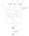
圖1是描繪根據本創作的實施例的CVD反應器的示意圖。FIG. 1 is a schematic diagram depicting a CVD reactor according to an embodiment of the present creation.
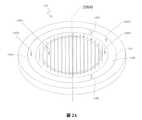
圖2A是根據本創作的實施例的噴射器塊的立體圖。2A is a perspective view of an injector block according to an embodiment of the present creation.
圖2B是描繪圖2A的噴射器塊的橫截面圖。2B is a cross-sectional view depicting the injector block of FIG. 2A.
圖3A繪示了根據本創作的實施例的噴射器塊上的第一反應氣體出口和第二反應氣體出口的對稱佈置。FIG. 3A illustrates a symmetrical arrangement of the first reaction gas outlet and the second reaction gas outlet on the injector block according to an embodiment of the present creation.
圖3B繪示了根據本創作的實施例的噴射器塊上的第一反應氣體出口和第二反應氣體出口的非對稱佈置。FIG. 3B illustrates the asymmetric arrangement of the first reaction gas outlet and the second reaction gas outlet on the injector block according to an embodiment of the present creation.
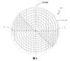
圖4繪示了根據本創作的實施例的沿非對稱佈置的噴射器塊的分配出口的點跡線。FIG. 4 illustrates the dot traces along the distribution outlets of asymmetrically arranged ejector blocks according to an embodiment of the present creation.
圖5是根據本創作的實施例的對應於對稱佈置和非對稱佈置的噴射器塊的CVD生長速率的圖示。FIG. 5 is a graph of CVD growth rates corresponding to symmetrically and asymmetrically arranged injector blocks according to an embodiment of the present creation.
圖6繪示了根據本創作的實施例的在CVD製程期間反應氣體流入處理室的操作流程。FIG. 6 illustrates an operation flow of reactant gas flowing into the processing chamber during the CVD process according to an embodiment of the present creation.
本申請要求2018年4月13日提交的編號為62/657,255的美國臨時申請的權益,該臨時申請透過引用而全部併入本文。This application claims the benefits of the US provisional application numbered 62/657,255 filed on April 13, 2018, which is incorporated by reference in its entirety.
參照圖1,根據本創作的實施例繪示了CVD反應器100的示意圖。反應器100限定處理室102,處理室102配置為用作處理環境空間。氣體分配裝置或噴射器塊104佈置在處理室102的一端。處理室102的佈置有噴射器塊104的端部可以稱為處理室102的“頂部”端。處理室的這一端通常(但不是必須地)在正常重力參考系中設置在處理室的頂部。因此,無論指示是否與重力向上和向下方向對準,這裡使用的向下方向都指的是遠離噴射器塊104的方向;而向上方向指的是處理室內朝向噴射器塊104的方向。類似地,這裡可以參照處理室102和噴射器塊104的參照係描述元件的“頂”表面和“底”表面。Referring to FIG. 1, a schematic diagram of a
噴射器塊104可以可操作地耦接到一個或多個反應氣體(製程氣體/載氣)源106A/B,其用於供應待在CVD製程中使用的氣體(例如反應氣體和載氣)。噴射器塊104佈置為接收來自反應氣體源106A/B的各種氣體,並將氣流108A/B沿大致向下的方向引導到處理室102中。在部分實施例中,噴射器塊104包括冷卻劑系統110,冷卻劑系統110配置為使冷卻流體循環以在操作期間將噴射器塊104保持在期望的溫度。冷卻劑系統110還可以配置為使冷卻流體循環通過處理室102的壁。處理室102還配備有排氣系統112,該排氣系統112配置為從處理室102的內部除去廢氣,從而使得氣體能夠從噴射器塊104沿向下方向連續流動。The
主軸114可佈置在處理室102內,使得主軸114的中心軸線116沿向上方向/向下方向延伸。主軸114可以透過結合有軸承和密封件的傳統轉動直通裝置安裝在處理室102內,使得主軸114可以轉動,同時又與處理室102的壁保持密封。The
晶圓載器120可以可解除地安裝到主軸114的頂端。晶圓載器120可以具有一個或多個凹槽122,晶圓保持在該一個或多個凹槽122中,並且半導體材料可以外延生長到該一個或多個凹槽122上。晶圓載器120可以具有圍繞中心軸線116佈置的大致圓形的橫截面。加熱元件124可以安裝在處理室102內並且至少部分地圍繞主軸114。因此,在部分實施例中,處理室102、噴射器塊104、主軸114、晶圓載器120和加熱元件124圍繞中心軸線116對稱地佈置。主軸114可以連接到配置為以期望的速度使主軸114和晶圓載器120轉動的轉動驅動機構126(例如電機驅動器)。在部分實施例中,轉動驅動機構配置為以介於50RPM至1500RPM的轉動速度使主軸114轉動。The
製程氣體可以透過噴射器塊104引入處理室102中。在引入後,製程氣體向下朝向晶圓載器120通過,並在保持晶圓的晶圓載器120的頂表面128上方通過。製程氣體流108A/B繼續圍繞晶圓載器120的周邊流動,並且最終通過排氣系統112從處理室102排出。通常,頂表面128附近的製程氣體主要由載氣(例如H2和/或N2)組成,其具有一定量的第一反應氣體組分和第二反應氣體組分。在部分實施例中,第一反應氣體組分可以是烷基源III族金屬,第二反應氣體組分可以是氫化物源V族元素。Process gas can be introduced into the
加熱元件124可以主要透過輻射熱傳遞將熱量傳遞給晶圓載器120。在其他實施例中,可以透過感應熱傳遞加熱晶圓載器120。從加熱元件124所施加的熱量透過晶圓載器120的主體向上傳遞到晶圓載器120的頂表面128。晶圓載器120的頂表面128上的一部分熱量被傳遞到晶圓和在頂表面上方通過的製程氣體108A/B。非特意地,一部分熱量也被傳遞到處理室102內的較冷的元件(例如處理室102的壁和噴射器塊104的壁)。The
希望將熱解氣體在其積聚在這些冷卻器結構的任一者上之前從處理室102中除去,這尤其是因為冷凝可以在相對較冷的表面上更快地發生。為了幫助除去熱解氣體,在部分實施例中,處理室102的壁結構可以形成配置為激勵向下氣流的上側遮板和下側遮板,從而減少或消除任何渦流,否則渦流會使熱解氣體反向再循環向上朝向相對較冷的表面(例如噴射器塊104)造成冷凝。It is desirable to remove the pyrolysis gas from the
噴射器塊104的改進可以進一步促進晶圓載器120的整個頂表面128上的更加一致的生長速率。額外地,噴射器塊104的改進可以促進對處理室102內的反應氣體的更有效使用,使得較少量的未使用的反應氣體從處理室102排出,從而顯示與現有技術的CVD反應器相比顯著節省了操作成本。The improvement of the
參照圖2A,根據本創作的實施例繪示了噴射器塊104的立體圖。圖2B繪示了圖2A的噴射器塊104的橫截面圖。在一些實施例中,噴射器塊104可替代地稱為氣體分配裝置和/或冷板。噴射器塊104定位於處理室102的頂端。噴射器塊104可具有上游表面130和下游表面132(如圖2B所示)。噴射器塊104的下游表面132可面向下游方向,朝向晶圓載器120和晶圓。噴射器塊104可以可操作地耦接到一個或多個反應氣體源106A/B,從而能夠分配反應氣體和載氣。噴射器塊104還可以可操作地耦接到冷卻劑系統110(如圖1所示),從而使冷卻劑能夠流過噴射器塊104的一部分,以幫助將反應氣體和載氣保持在期望的溫度。2A, a perspective view of the
在部分實施例中,一個或多個第一氣體源106A1-2(替代地稱為第一反應氣體入口)可以配置為將通常與載氣(例如H2和/或N2)混合的第一反應氣體(例如III族烷基金屬)供應給噴射器塊104。第一反應物氣體入口106A1-2可以與第一反應物流動路徑134流體連通。在部分實施例中,流動路徑134可以是限定在噴射器塊104的一部分內的管道。例如,在部分實施例中,流動路徑134可配置為定位在噴射器塊104的周邊附近一個或多個環形通道。在部分實施例中,流動路徑134被定義為具有一個或多個分隔部138A/B(或者稱為擋板)的環形溝槽,從而將烷基或第一反應物流動路徑134分成第一反應氣體第一區域140A和第一反應氣體第二區域140B。額外地參照圖2B,在一些實施例中,第一反應氣體第一區域和第二區域140A/B可以透過一個或多個板141A/B至少部分地被密封。In some embodiments, one or more first gas sources 106A1-2 (alternatively referred to as a first reactant gas inlet) may be configured to mix the first with the carrier gas (eg, H2 and/or N2 ) The reaction gas (for example, Group III metal alkyl) is supplied to the
如圖2B所示,相應的第一反應氣體第一區域和第二區域140A/B可包括橫穿噴射器塊104的一部分的多個分配通道142A/B。在一些實施例中,分配通道142A/B可線性地橫穿噴射器塊104的一部分。在部分實施例中,對分配通道142A/B進行限定的壁的下部分可以限定沿分配通道142A/B縱向延伸的分配出口144A/B,從而使得分配通道142A/B內的第一反應氣體能夠被引入到處理室102內。在一些實施例中,分配出口144A/B還可以穿過噴嘴以呈現期望的分配流動。As shown in FIG. 2B, the respective first and
在一些實施例中,第一數量的第一反應氣體流入第一反應氣體入口106A1,穿過第一反應氣體第一區域140A,並穿過由第一分配通道142A限定的相應的分配出口144A流出。第二數量的第一反應氣體流入第二反應器氣體入口106A2,穿過第二區域140B,並穿過由第二分配通道142B限定的相應的分配出口144B流出。此後,第一反應氣體向下流入處理室102內,朝向晶圓載器120和晶圓。In some embodiments, a first amount of first reaction gas flows into the first reaction gas inlet 106A1, passes through the first reaction gas
在一些實施例中,第一反應氣體第一區域140A可包括比第一反應氣體第二區域140B更多數量的分配通道142A和/或分配出口144A。例如,如圖所示,在部分實施例中,存在十四個第一分配通道142A和三個第二分配通道142B。在其他實施例中,預期了其他數量的分配通道。在一些實施例中,第一反應氣體的流速在噴射器塊104上可以大體一致(例如,第一區域140A和第二區域140B之間的流速可以大體相等)。在其他實施例中,第一區域140A內的第一反應氣體的流速可以相對高於或低於第二區域140B內的流速。在一些實施例中,相對於供應到第一入口106A1的反應氣體的濃度,到第二入口106A2的第一反應氣體供應源可具有更高濃度的反應氣體。在其他實施例中,到第一入口和第二入口106A1-2的反應氣體供應源的濃度可以大體相等。In some embodiments, the first reaction gas
在部分實施例中,噴射器塊104可包括配置為將通常與載氣(例如H2和/或N2)混合的第二反應氣體(例如V族氫化物)供應到噴射器塊104的一個或多個第二反應氣體入口106B1-2。第二反應氣體入口106B1-2可與第二反應物流動路徑和/或分配通道150A-B流體連通。分配通道150可以配置為一個或多個環形通道、線性通道或其組合。在部分實施例中,第二反應物分配通道150A-B可以分成第一區域151A和第二區域151B。在一些實施例中,第二區域151B可以至少部分地圍繞第一區域151A。在部分實施例中,第一區域151A可以透過溝槽或分隔部153與第二區域151B分隔開。In some embodiments, the
第一區域和第二區域151A/B內的相應的第二反應氣體可以與多個第二反應氣體出口152A/B流體連通。在部分實施例中,第二反應氣體出口152A/B通常可以定位於第一區域和第二區域151A/B下方,從而使第一區域和第二區域151A/B內的第二反應氣體能夠被引入處理室102中。在一些實施例中,分配出口152穿過擴散器,擴散器在一些實施例中可以被限定在相鄰的第一反應氣體出口噴嘴之間。因此,在部分實施例中,至少一部分第二反應氣體出口152A-B可以穿插有至少一部分第一反應氣體分配出口144。The corresponding second reaction gas in the first and
在部分實施例中,第一數量的第二反應氣體流入第二反應氣體入口106B1,進入第二反應氣體第一區域151A的相應的第一分配通道150A,並穿過相應的第二反應氣體出口152A流出。第二數量的第二反應氣體流入第二反應氣體入口106B2,進入第二反應氣體第二區域151B的第二分配通道150B,並穿過相應的第二反應氣體出口152B流出。此後,第二反應氣體向下流入處理室102內,朝向晶圓載器120和晶圓。In some embodiments, the first amount of second reaction gas flows into the second reaction gas inlet 106B1, enters the corresponding
在一些實施例中,第二反應氣體第一區域可包括比第二反應氣體第二區域更多數量的分配出口152。在一些實施例中,第二反應氣體的流速在噴射器塊104上可以大體一致(例如,第一區域151A和第二區域151B之間的流速可以大體相等)。在其他實施例中,第一區域151A內的第二反應氣體的流速可以相對高於或低於第二區域151B的流速。在一些實施例中,相對於供應到第二入口106B2的反應氣體的濃度,到第一入口106B1的第二反應氣體的供應源可具有更高濃度的反應氣體。例如,在部分實施例中,第二區域151B內的氣體可主要由H2和/或N2組成,而第一區域151A則用作主要氫化物源。在其他實施例中,到第一入口和第二入口106B1-2的反應氣體供應源的濃度可以大體相等。In some embodiments, the first reaction gas second region may include a greater number of
參照圖3A至3B,氣體分配出口144/152可以相對於噴射器塊104的對稱軸對稱或非對稱。如圖3A所示,對稱軸的兩側上的分配出口144定位為距對稱軸相等的距離(例如,D1等於D2);因此,圖3A表示分配出口144/152的對稱佈置。相反,如圖3B所示,對稱軸兩側上的分配出口定位於距對稱軸不相等的距離處(例如,D3不等於D4);因此,圖3B表示分配出口144/152的非對稱佈置。在任一種情況下,多個分配出口144/152在噴射器塊104上可以彼此等間距分隔開;相反,對稱和非對稱佈置之間的差異取決於分佈出口網路與對稱軸的間距。3A to 3B, the
如圖4所示,非對稱佈置提供了噴射器塊104下方的流動均勻性的改進。具體地,由於晶圓載器120總體上圍繞噴射器塊104下方的對稱軸轉動,所以沿著定位在對稱軸一側上的出口144/152的給定點P1將追蹤與沿著定位在對稱軸的相對側上的出口144/152的給定點P2的同心圓不同的同心圓。因此,在一些實施例中,可以有效地減小分配出口144/152之間的有效間隔(例如減少50%),從而改善反應氣體分佈和CVD生長的均勻性。參照圖5,根據本創作的實施例繪示了對應於對稱出口分佈和非對稱出口分佈的CVD生長速率的圖示。在CVD生長速率均勻性上的改進使得非對稱噴射器塊的分配出口144/152能夠進一步間隔開,這表示降低了製造成本,並且在一些情況下改善了氣流,這是由於各種分配通道的尺寸可以做得更大。As shown in FIG. 4, the asymmetrical arrangement provides improved flow uniformity under the
參照圖6,根據本創作的實施例繪示了CVD反應器100的橫截面圖,其示出了在CVD製程期間處理室102內的反應氣體濃度和流動線。在操作中,與一種或多種載氣(如H2和/或N2)混合的第一反應氣體(例如III族烷基金屬)通過第一反應氣體入口106A1-2供應到相應的第一區域和第二區域140A/B中,並且經由多個第一反應氣體出口144A/B引射到處理室102中。類似地,也與一種或多種載氣混合的第二反應氣體(例如V族氫化物)被供應到第二反應氣體入口106B1-2,進入相應的第一區域和第二區域151A/B,並且經由多個第二反應氣體出口152A/B被引射到處理室102中。因此,第一反應氣體和第二反應氣體作為一系列細長的簾狀氣流從相應的第一反應氣體出口144A/B和第二反應氣體出口152A/B發出。Referring to FIG. 6, a cross-sectional view of the
當第一反應氣體和第二反應氣體接近轉動的晶圓載器120時,反應氣體的溫度顯著增加,並且轉動的晶圓載器120的黏滯阻力促使第一氣體和第二氣體圍繞晶圓載器120的軸轉動,使得在晶圓載器120的頂表面附近的邊界區域中,氣體圍繞軸線流動並且向外朝向晶圓載器120的周邊。根據在該製程中使用的反應氣體不同,熱解可以以介於噴射器塊104的溫度和晶圓載器120溫度之間的中間溫度發生在邊界區域中或其附近。這種熱解有利於反應氣體的交互作用和晶體結構的生長。未沉積的氣體繼續流向周邊並流過載器120的外邊緣,在那裡其可以透過設置在晶圓載器120下方的一個或多個排氣口從處理室102移除。When the first reactive gas and the second reactive gas approach the
在一些實施例中,從第二區域140B發出的第一反應氣體可以具有相對於從第一區域140A發出的第一反應氣體更高濃度的III族烷基金屬,並且第二反應氣體第二區域151B(其可以至少部分地圍繞第二反應氣體第一區域151A)可以具有相對於第二反應氣體第一區域151A更高濃度的載氣。第一反應氣體第二區域140B中的III族烷基金屬的增加的濃度以及第二反應氣體第二區域151B中的V族氫化物的降低的濃度可用於改善生長均勻性並促進反應物化學物質在CVD製程中的更有效的使用,從而降低生產成本並提高品質。In some embodiments, the first reaction gas emitted from the
應當理解的是,只要教導仍然是可操作的,則在本教導的方法中使用的各個步驟可以以任何順序和/或同時執行。此外,應當理解的是,只要教導仍然是可操作的,則本教導的裝置和方法可以包括任何數量的或全部的所描述實施例。It should be understood that as long as the teachings are still operable, the various steps used in the methods of the present teachings can be performed in any order and/or simultaneously. Furthermore, it should be understood that the device and method of the present teaching may include any number or all of the described embodiments as long as the teaching is still operable.
本文已經描述了系統、裝置和方法的各種實施例。這些實施例僅作為示例給出,並不旨在限制本發明的範圍。此外,應當理解的是,已經描述的實施例的各種特徵可以以各種方式組合以生成許多附加的實施例。此外,雖然已經描述了各種材料、尺寸、形狀、配置和位置等以用於所公開的實施例,但是,在不超出本發明的範圍的情況下,可以使用除了所公開的那些之外的其他材料。此外,說明書中對“一個實施例”,“實施例”或“一些實施例”的引用意味著結合實施例描述的特定特徵、結構或特性包括在教導的至少一個實施例中。在說明書中各處出現的短語“在部分實施例中”不一定都指的是同一實施例。Various embodiments of systems, devices and methods have been described herein. These embodiments are given as examples only, and are not intended to limit the scope of the present invention. Furthermore, it should be understood that the various features of the embodiments that have been described can be combined in various ways to generate many additional embodiments. In addition, although various materials, sizes, shapes, configurations, positions, etc. have been described for the disclosed embodiments, other than those disclosed can be used without departing from the scope of the present invention material. In addition, references in the specification to "one embodiment", "an embodiment" or "some embodiments" mean that a particular feature, structure or characteristic described in connection with the embodiment is included in at least one embodiment of the teaching. The appearance of the phrase "in some embodiments" throughout the specification does not necessarily refer to the same embodiment.
本技術領域中具有通常知識者將認識到,本文的主題可包括比上述任何單獨實施例中所示的更少的特徵。本文所描述的實施例並不意味著是對可以組合本主題的各種特徵的方式的詳盡表示。因此,實施例不是相互排斥的特徵組合;相反,正如本技術領域中具有通常知識者所理解的,各種實施例可包括選自不同的個別實施例的不同個別特徵的組合。此外,除非另有說明,否則關於一個實施例所描述的元件也可以在其他實施例中實現,即使在這些實施例中沒有對其進行描述。Those of ordinary skill in the art will recognize that the subject matter herein may include fewer features than shown in any individual embodiment described above. The embodiments described herein are not meant to be an exhaustive representation of the ways in which the various features of the subject matter can be combined. Therefore, the embodiments are not mutually exclusive combinations of features; rather, as those of ordinary skill in the art understand, various embodiments may include combinations of different individual features selected from different individual embodiments. In addition, unless otherwise stated, elements described in relation to one embodiment can also be implemented in other embodiments, even if they are not described in these embodiments.
100:反應器100: reactor
102:處理室102: processing room
104:噴射器塊104: injector block
106A:反應氣體源106A: reactive gas source
106B:載氣源106B: Carrier gas source
108A:製程氣體流108A: Process gas flow
108B:製程氣體流108B: Process gas flow
110:冷卻劑系統110: coolant system
112:排氣系統112: Exhaust system
114:主軸114: Spindle
116:中心軸線116: Central axis
120:晶圓載器120: Wafer carrier
122:凹槽122: groove
124:加熱元件124: heating element
126:轉動驅動機構126: Rotating drive mechanism
128:頂表面128: top surface
Claims (26)
Translated fromChineseApplications Claiming Priority (2)
| Application Number | Priority Date | Filing Date | Title |
|---|---|---|---|
| US201862657255P | 2018-04-13 | 2018-04-13 | |
| US62/657,255 | 2018-04-13 |
Publications (1)
| Publication Number | Publication Date |
|---|---|
| TWM597506Utrue TWM597506U (en) | 2020-06-21 |
Family
ID=68161466
Family Applications (2)
| Application Number | Title | Priority Date | Filing Date |
|---|---|---|---|
| TW108204554UTWM597506U (en) | 2018-04-13 | 2019-04-12 | Chemical vapor deposition apparatus with multi-zone injector block |
| TW108112969ATWI809088B (en) | 2018-04-13 | 2019-04-12 | Chemical vapor deposition apparatus with multi-zone injector block |
Family Applications After (1)
| Application Number | Title | Priority Date | Filing Date |
|---|---|---|---|
| TW108112969ATWI809088B (en) | 2018-04-13 | 2019-04-12 | Chemical vapor deposition apparatus with multi-zone injector block |
Country Status (6)
| Country | Link |
|---|---|
| US (1) | US20190316258A1 (en) |
| JP (1) | JP7495882B2 (en) |
| CN (2) | CN210030883U (en) |
| DE (1) | DE112019001953T5 (en) |
| TW (2) | TWM597506U (en) |
| WO (1) | WO2019200312A1 (en) |
Families Citing this family (3)
| Publication number | Priority date | Publication date | Assignee | Title |
|---|---|---|---|---|
| JP7256135B2 (en)* | 2017-06-23 | 2023-04-11 | メルク パテント ゲゼルシャフト ミット ベシュレンクテル ハフツング | Atomic layer deposition method for selective film growth |
| TWM597506U (en)* | 2018-04-13 | 2020-06-21 | 美商維高儀器股份有限公司 | Chemical vapor deposition apparatus with multi-zone injector block |
| US11225716B2 (en)* | 2019-11-27 | 2022-01-18 | Tokyo Electron Limited | Internally cooled multi-hole injectors for delivery of process chemicals |
Family Cites Families (20)
| Publication number | Priority date | Publication date | Assignee | Title |
|---|---|---|---|---|
| US5552017A (en)* | 1995-11-27 | 1996-09-03 | Taiwan Semiconductor Manufacturing Company | Method for improving the process uniformity in a reactor by asymmetrically adjusting the reactant gas flow |
| US6302964B1 (en)* | 1998-06-16 | 2001-10-16 | Applied Materials, Inc. | One-piece dual gas faceplate for a showerhead in a semiconductor wafer processing system |
| JP4487338B2 (en)* | 1999-08-31 | 2010-06-23 | 東京エレクトロン株式会社 | Film forming apparatus and film forming method |
| JP2002110567A (en)* | 2000-10-03 | 2002-04-12 | Mitsubishi Electric Corp | Chemical vapor deposition apparatus and method for forming semiconductor wafer by using the apparatus |
| US20060191637A1 (en)* | 2001-06-21 | 2006-08-31 | John Zajac | Etching Apparatus and Process with Thickness and Uniformity Control |
| US6590344B2 (en)* | 2001-11-20 | 2003-07-08 | Taiwan Semiconductor Manufacturing Co., Ltd. | Selectively controllable gas feed zones for a plasma reactor |
| KR100513920B1 (en)* | 2003-10-31 | 2005-09-08 | 주식회사 시스넥스 | Chemical vapor deposition unit |
| US20060196417A1 (en)* | 2005-03-03 | 2006-09-07 | Taiwan Semiconductor Manufacturing Co., Ltd. | Gas distribution systems for deposition processes |
| US20080078746A1 (en)* | 2006-08-15 | 2008-04-03 | Noriiki Masuda | Substrate processing system, gas supply unit, method of substrate processing, computer program, and storage medium |
| US20080314311A1 (en)* | 2007-06-24 | 2008-12-25 | Burrows Brian H | Hvpe showerhead design |
| TW201030178A (en)* | 2008-10-10 | 2010-08-16 | Alta Devices Inc | Concentric showerhead for vapor deposition |
| CN105420688B (en)* | 2008-12-04 | 2019-01-22 | 威科仪器有限公司 | Air inlet element and its manufacturing method for chemical vapor deposition |
| TW201237994A (en)* | 2010-12-20 | 2012-09-16 | Novellus Systems Inc | System and apparatus for flowable deposition in semiconductor fabrication |
| US9447499B2 (en)* | 2012-06-22 | 2016-09-20 | Novellus Systems, Inc. | Dual plenum, axi-symmetric showerhead with edge-to-center gas delivery |
| DE102013101534A1 (en)* | 2013-02-15 | 2014-08-21 | Aixtron Se | Gas distributor for a CVD reactor |
| US20140284404A1 (en)* | 2013-03-20 | 2014-09-25 | Asm Technology Singapore Pte Ltd. | Chemical vapour deposition injector |
| CN105441904B (en)* | 2014-06-18 | 2018-06-26 | 中微半导体设备(上海)有限公司 | Gas shower device, chemical vapor deposition unit and method |
| JP5837962B1 (en)* | 2014-07-08 | 2015-12-24 | 株式会社日立国際電気 | Substrate processing apparatus, semiconductor device manufacturing method, and gas rectifier |
| US10358722B2 (en)* | 2015-12-14 | 2019-07-23 | Lam Research Corporation | Showerhead assembly |
| TWM597506U (en)* | 2018-04-13 | 2020-06-21 | 美商維高儀器股份有限公司 | Chemical vapor deposition apparatus with multi-zone injector block |
- 2019
- 2019-04-12TWTW108204554Upatent/TWM597506U/enunknown
- 2019-04-12DEDE112019001953.8Tpatent/DE112019001953T5/enactivePending
- 2019-04-12TWTW108112969Apatent/TWI809088B/enactive
- 2019-04-12JPJP2020555785Apatent/JP7495882B2/enactiveActive
- 2019-04-12USUS16/383,321patent/US20190316258A1/enactivePending
- 2019-04-12WOPCT/US2019/027312patent/WO2019200312A1/ennot_activeCeased
- 2019-04-15CNCN201920505560.0Upatent/CN210030883U/enactiveActive
- 2019-04-15CNCN201910300090.9Apatent/CN110373653B/enactiveActive
Also Published As
| Publication number | Publication date |
|---|---|
| JP7495882B2 (en) | 2024-06-05 |
| TWI809088B (en) | 2023-07-21 |
| JP2021521332A (en) | 2021-08-26 |
| CN110373653B (en) | 2023-12-01 |
| CN110373653A (en) | 2019-10-25 |
| US20190316258A1 (en) | 2019-10-17 |
| TW201946125A (en) | 2019-12-01 |
| DE112019001953T5 (en) | 2021-01-21 |
| CN210030883U (en) | 2020-02-07 |
| WO2019200312A1 (en) | 2019-10-17 |
Similar Documents
| Publication | Publication Date | Title |
|---|---|---|
| CN101413112B (en) | Multi-gas straight channel showerhead | |
| CN102272892B (en) | Chemical vapor deposition with elevated temperature gas injection | |
| TWI791100B (en) | MOCVD reactor | |
| US9593434B2 (en) | Alkyl push flow for vertical flow rotating disk reactors | |
| KR101610638B1 (en) | Vapor phase growing apparatus and vapor phase growing method | |
| KR20070107782A (en) | Chemical Vapor Deposition Reactor with Multiple Inlets | |
| CN101423937A (en) | Multi-gas concentric injection showerhead | |
| TWI521089B (en) | Vapor phase film deposition apparatus | |
| TWI809088B (en) | Chemical vapor deposition apparatus with multi-zone injector block | |
| TW201606120A (en) | Gas flow flange for a rotating disk reactor for chemical vapor deposition | |
| TW201108305A (en) | Gas phase growing apparatus for group III nitride semiconductor | |
| JP5064132B2 (en) | Vapor growth apparatus and method for manufacturing semiconductor device | |
| US10570510B2 (en) | Periphery purge shutter and flow control systems and methods | |
| JP2009032785A (en) | Vapor growth apparatus and method for manufacturing semiconductor device | |
| TWI545224B (en) | Inlet system for metal organic chemical vapor deposition apparatus | |
| CN105624648B (en) | Film growth chamber and film grower | |
| JP2008053669A (en) | Crystal growing method, and device using temperature-controlled process gas | |
| JPH08213328A (en) | Metal-organic vapor phase epitaxy apparatus and metal-organic vapor phase growth method using the same |