Movatterモバイル変換


[0]ホーム

URL:


TWM596873U - Optical system of miniature head-mounted display - Google Patents

Optical system of miniature head-mounted display
Download PDF

Info

Publication number
TWM596873U
TWM596873UTW109202571UTW109202571UTWM596873UTW M596873 UTWM596873 UTW M596873UTW 109202571 UTW109202571 UTW 109202571UTW 109202571 UTW109202571 UTW 109202571UTW M596873 UTWM596873 UTW M596873U
Authority
TW
Taiwan
Prior art keywords
optical system
lens
polarized light
mounted display
phase delay
Prior art date
Application number
TW109202571U
Other languages
Chinese (zh)
Inventor
洪淩桂
施富斌
游鴻文
Original Assignee
雙瑩科技股份有限公司
Priority date (The priority date is an assumption and is not a legal conclusion. Google has not performed a legal analysis and makes no representation as to the accuracy of the date listed.)
Filing date
Publication date
Application filed by 雙瑩科技股份有限公司filedCritical雙瑩科技股份有限公司
Priority to TW109202571UpriorityCriticalpatent/TWM596873U/en
Publication of TWM596873UpublicationCriticalpatent/TWM596873U/en

Links

Images

Abstract

Translated fromChinese

本創作為一種微型頭戴式顯示器之光學系統,包括一部分反射部分穿透元件對應顯示裝置設置,以將其發出的偏振光部分穿透出去;相位延遲元件對應部分反射部分穿透元件設置,以對偏振光相位延遲,成為另一偏振態之偏振光;一第一透鏡對應部分反射部分穿透元件與相位延遲元件設置,以接收偏振光,調節偏振光焦距;反射式偏振元件接收另一偏振態之偏振光並反射,使另一偏振態之偏振光經過相位延遲元件及部分反射部分穿透元件後,再反射回反射式偏振元件並穿透至第二透鏡,以將其導入偏振光人眼中。本創作利用光線的相位延遲及多次反射達到近似長度的光程,可縮短顯示裝置和光學模系統的距離,且雙透鏡的設置,能修正像差,並擴大視場角。This creation is an optical system for a miniature head-mounted display. It includes a part of the reflective part penetrating element corresponding to the display device to transmit the polarized light emitted by it; the phase delay element is corresponding to the partial reflective part penetrating element. Phase retardation of polarized light becomes polarized light of another polarization state; a first lens corresponding to the partial reflection part penetrating element and phase delay element are arranged to receive polarized light and adjust the focal length of polarized light; the reflective polarizing element receives another polarization Polarized light of the other state and reflected, so that the polarized light of the other polarized state passes through the phase delay element and the partially reflective partial penetrating element, and then reflects back to the reflective polarizing element and penetrates to the second lens to introduce it into the polarized light Eyes. This creation uses the phase delay of light and multiple reflections to achieve an approximate optical path length, which can shorten the distance between the display device and the optical mode system, and the dual lens setting can correct aberrations and expand the angle of view.

Description

Translated fromChinese
微型頭戴式顯示器之光學系統Optical system of miniature head-mounted display

本創作係有關一種光學元件、系統或儀器,特別是指一種微型頭戴式顯示器之光學系統。This creation relates to an optical element, system or instrument, especially an optical system of a miniature head-mounted display.

虛擬實境(virtual reality,VR)是指一種利用電腦技術產生一個三維空間的虛擬影像,並將其影像投射至使用者眼中,令使用者感受到身入其境的技術。目前用來實現虛擬實境之技術,多半是令使用者將虛擬實境裝置穿戴在頭部,使虛擬實境裝置中的顯示螢幕能貼近使用者的眼部,令使用者在一個短距離能看到屏寬超過90度的顯示影像。Virtual reality (VR) refers to a technology that uses computer technology to generate a virtual image in a three-dimensional space and project the image into the user's eyes, so that the user feels that he is in the environment. The current technology used to implement virtual reality is mostly to enable users to wear the virtual reality device on their heads, so that the display screen in the virtual reality device can be close to the user's eyes, so that the user can See the display image with a screen width exceeding 90 degrees.

請參照第一圖,以說明一般頭戴式顯示器之技術,習知頭戴式顯示器包括有顯示螢幕90以及一光學模組92,顯示螢幕90的影像可投射在光學模組92上,使光學模組92能調整影像的聚焦位置,將影像近距離投射在人眼94。顯示螢幕90所投射的影像會經過一段光程為d的光路後,再進入到光學模組92,舉例來說,若光程d為40公厘(mm),則頭戴顯示器中顯示螢幕90與光學模組92的距離就至少為40公厘(mm),除此之外加上光學模組92、適眼距以及戴式顯示器外殼,使得頭戴式顯示器後必然大於40mm。Please refer to the first figure to explain the general head-mounted display technology. The conventional head-mounted display includes adisplay screen 90 and anoptical module 92. The image of thedisplay screen 90 can be projected on theoptical module 92 to make the optical Themodule 92 can adjust the focus position of the image and project the image on thehuman eye 94 at close range. The image projected by thedisplay screen 90 will go through an optical path with an optical path of d, and then enter theoptical module 92. For example, if the optical path d is 40 millimeters (mm), thescreen 90 is displayed in the head-mounted display The distance to theoptical module 92 is at least 40 millimeters (mm). In addition, theoptical module 92, the eye distance, and the housing of the head-mounted display make the head-mounted display necessarily larger than 40 mm.

因此,目前的頭戴式顯示器結構使得裝置相當笨重,當使用者穿戴在頭上時,可能因頭戴式顯示器體積過大或重量過重,造成穿戴上的不適,令使用者無法長時間穿戴等問題產生,故將頭戴顯示器的厚度縮小、便於使用者配戴使用為一項重要的課題。Therefore, the current head-mounted display structure makes the device quite bulky. When the user wears it on the head, the head-mounted display may be too bulky or heavy, which may cause discomfort in wearing and prevent the user from wearing for a long time. Therefore, it is an important issue to reduce the thickness of the head-mounted display and facilitate the user to wear and use it.

有鑑於此,本創作遂針對上述習知技術之缺失,提出一種,以有效克服上述之該等問題。In view of this, the author proposes a solution to the above-mentioned lack of conventional technology to effectively overcome the above-mentioned problems.

本創作之主要目的在提供一種微型頭戴式顯示器之光學系統,其透過雙透鏡的設置,能有效修正影像的像差,並擴大視場角的範圍。The main purpose of this creation is to provide an optical system for a miniature head-mounted display, which can effectively correct the aberration of the image and expand the range of the angle of view through the setting of the double lens.

本創作之另一目的在提供一種微型頭戴式顯示器之光學系統,其在頭戴顯示器的光學系統設置反射式偏振元件、相位延遲元件、部分反射部分穿透元件等光學元件,利用光線的相位延遲及多次反射達到近似長度的光程,藉以縮短顯示裝置和光學模系統之間的距離,以將頭戴顯示器微型化。Another purpose of this creation is to provide an optical system for a miniature head-mounted display. The optical system of the head-mounted display is provided with optical elements such as a reflective polarizing element, a phase delay element, a partially reflective partial penetrating element, etc. The delay and multiple reflections reach the optical path of approximate length, thereby shortening the distance between the display device and the optical mode system to miniaturize the head-mounted display.

為達上述之目的,本創作提供一種微型頭戴式顯示器之光學系統,其可接收顯示裝置之輸出影像及其偏振光,光學系統包括一部分反射部分穿透元件對應顯示裝置設置,部分反射部分穿透元件可將偏振光部分反射,部分穿透出部分反射部分穿透元件;一相位延遲元件對應部分反射部分穿透元件設置,相位延遲元件接收穿透部分反射部分穿透元件之偏振光,並對其進行相位延遲,成為另一偏振態之該偏振光;一第一透鏡對應部分反射部分穿透元件與相位延遲元件設置,以接收該偏振光,調節偏振光焦距;一反射式偏振元件對應相位延遲元件設置,以接收另一偏振態之偏振光並反射,使另一偏振態之偏振光經過相位延遲元件及部分反射部分穿透元件後,再反射回反射式偏振元件並穿透至一第二透鏡,第二透鏡對應反射式偏振元件設置,接收穿透反射式偏振元件之偏振光,並將其導入人眼中。To achieve the above purpose, the present invention provides an optical system for a micro head-mounted display, which can receive the output image of the display device and its polarized light. The optical system includes a part of the reflective part penetrating element corresponding to the display device, and a part of the reflective part The transmissive element can partially reflect polarized light and partially penetrate out of the partially reflective partially penetrating element; a phase delay element is provided corresponding to the partially reflective partially penetrating element, and the phase delay element receives polarized light penetrating the partially reflecting part penetrating element, and Phase-delay it to become the polarized light of another polarization state; a first lens corresponding to the partial reflection part penetrating element and the phase delay element are arranged to receive the polarized light and adjust the polarized light focal length; a reflective polarizing element corresponds to The phase delay element is set to connectReceive the polarized light of another polarization state and reflect it, so that the polarized light of another polarization state passes through the phase delay element and the partial reflection part penetrating element, then reflects back to the reflective polarizing element and penetrates to a second lens, the second The lens is arranged corresponding to the reflective polarizing element, receives polarized light penetrating the reflective polarizing element, and directs it into the human eye.

根據本創作之實施例,其中部分反射部分穿透元件係設置在第一透鏡上。According to an embodiment of the present invention, the partially reflecting and partially penetrating element is disposed on the first lens.

根據本創作之實施例,微型頭戴式顯示器之光學系統更包括一平面光學元件設置在第一透鏡與第二透鏡之間,令相位延遲元件及反射式偏振元件設置在平面光學元件上。According to the embodiment of the present invention, the optical system of the micro head-mounted display further includes a planar optical element disposed between the first lens and the second lens, so that the phase delay element and the reflective polarizing element are disposed on the planar optical element.

根據本創作之實施例,其中第二透鏡相鄰第一透鏡之一側設有一第二平面部,令相位延遲元件及反射式偏振元件設置於第二平面部。According to an embodiment of the present invention, a side of the second lens adjacent to the first lens is provided with a second plane portion, so that the phase delay element and the reflective polarizing element are disposed on the second plane portion.

根據本創作之實施例,其中反射式偏振元件係設置在第二透鏡上。According to an embodiment of the present invention, the reflective polarizing element is disposed on the second lens.

根據本創作之實施例,其中相位延遲元件係設置在一平面光學元件上。According to an embodiment of the present invention, the phase delay element is disposed on a planar optical element.

根據本創作之實施例,微型頭戴式顯示器之光學系統更包括一平面光學元件,設置於顯示裝置以及第一透鏡之間,部分反射部分穿透元件及相位延遲元件係設置在平面光學元件上。According to the embodiment of the present invention, the optical system of the micro head-mounted display further includes a planar optical element, which is disposed between the display device and the first lens, and the partially reflective partial transmissive element and the phase delay element are disposed on the planar optical element .

根據本創作之實施例,其中第一透鏡相鄰顯示裝置設置之一側具有一第一平面部,令部分反射部分穿透元件及相位延遲元件設置於第一平面部。According to an embodiment of the present invention, one side of the first lens adjacent to the display device has a first plane portion, so that the partially reflective partial transmission element and the phase delay element are arranged on the first plane portion.

茲為對本創作之結構特徵及所達成之功效更有進一步之瞭解與認識,謹佐以較佳之實施例圖及配合詳細之說明,說明如後。In order to have a further understanding and understanding of the structural characteristics and the achieved effect of this creation, I would like to use the preferred embodiment drawings and detailed descriptions to explain as follows.

10:部分反射部分穿透10: Partial reflection and partial penetration

12:第一透鏡12: the first lens

122:第一平面部122: The first plane

14:相位延遲元件14: Phase delay element

16:反射式偏振元件16: Reflective polarizing element

18:平面光學元件18: Flat optics

20:第二透鏡20: Second lens

202:第二平面部202: second plane

2:顯示裝置2: display device

90:顯示裝置90: display device

92:光學模組92: Optical module

94:人眼94: Human eye

A:偏振光A: polarized light

B:偏振光B: polarized light

C:偏振光C: polarized light

D:偏振光D: polarized light

第一圖係為先前技術中頭戴顯示器的顯示裝置與人眼之間的光程示意圖。The first figure is a schematic diagram of the optical path between the display device of the head-mounted display and the human eye in the prior art.

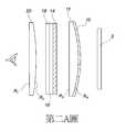
第二A圖係為本創作之第一實施例示意圖。The second figure A is a schematic diagram of the first embodiment of the creation.

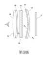
第二B圖係為本創作之第一實施例偏振光之光路示意圖。The second figure B is a schematic diagram of the optical path of polarized light according to the first embodiment of the creation.

第三圖係為本創作之第二實施例示意圖。The third diagram is a schematic diagram of the second embodiment of the creation.

第四圖係為本創作之第三實施例示意圖。The fourth figure is a schematic diagram of the third embodiment of the creation.

第五圖係為本創作之第四實施例示意圖。The fifth figure is a schematic diagram of the fourth embodiment of the creation.

第六圖係為本創作之第五實施例示意圖。The sixth figure is a schematic diagram of the fifth embodiment of the creation.

本創作提供一種微型頭戴式顯示器之光學系統,其能有效修正影像的像差,並擴大視場角的範圍,且能利用光線的相位延遲及多次反射達到近似長度的光程,藉以縮短顯示裝置和光學系統之間的距離,將頭戴式顯示器微型化。This creation provides an optical system for a miniature head-mounted display, which can effectively correct the aberration of the image and expand the range of the field of view, and can use the phase delay of light and multiple reflections to achieve an optical path of approximate length, thereby shortening The distance between the display device and the optical system miniaturizes the head-mounted display.

為了能瞭解本創作的結構設計,在此先詳述微型頭戴式顯示器之光學系統的結構組成,本創作之光學系統可供安裝在微型頭戴式顯示器中,光學系統接收微型頭戴式顯示器中顯示裝置的輸出影像及其偏振光,以呈現屏寬超過90度的顯示影像供使用者觀賞。請參照第二A圖,本實施例之光學系統係設置在微型頭戴式顯示器內,且位於顯示裝置2前端,光學系統之結構由顯示裝置2依序互相對應設置有一部分反射部分穿透元件10、一第一透鏡12、一相位延遲元件14、一反射式偏振元件16、一平面光學元件18及一第二透鏡20。其中第一透鏡12及第二透鏡20可為非球面透鏡、菲涅爾透鏡或多片透鏡之組合。In order to understand the structural design of this creation, the structural composition of the optical system of the micro head-mounted display is described in detail first. The optical system of this creation can be installed in the micro head-mounted display, and the optical system receives the micro head-mounted display The output image of the middle display device and its polarizationLight to present a display image with a screen width exceeding 90 degrees for the user to watch. Please refer to FIG. 2A. The optical system of this embodiment is disposed in a micro head-mounted display and is located at the front end of thedisplay device 2. The structure of the optical system is provided by thedisplay device 2 in sequence corresponding to each other with a part of reflectivepartial transmission elements 10. Afirst lens 12, aphase delay element 14, a reflective polarizingelement 16, a planaroptical element 18, and asecond lens 20. Thefirst lens 12 and thesecond lens 20 may be aspheric lenses, Fresnel lenses, or a combination of multiple lenses.

由顯示裝置2輸出之偏振光之型態可為線偏振光、圓偏振光或其他偏振態,因此顯示裝置2及部分穿透部分反射元件10之間更可依據顯示裝置2之偏振情況增加一個或複數個偏振調整元件(圖中未示),偏振調整元件可為線偏振元件、圓偏振元件、相位延遲元件或反射式偏振元件以對應調整顯示裝置2之偏振態。偏振調整元件可為薄膜材料或光學鍍膜等以塗佈、鍍膜或黏合等的形式設置於顯示裝置2或部分穿透部分反射元件10上。The type of polarized light output by thedisplay device 2 may be linearly polarized light, circularly polarized light, or other polarization states. Therefore, between thedisplay device 2 and the partially penetrating partialreflective element 10, an additional one can be added according to the polarization of thedisplay device 2 Or a plurality of polarization adjustment elements (not shown), the polarization adjustment elements may be linear polarization elements, circular polarization elements, phase delay elements or reflective polarization elements to adjust the polarization state of thedisplay device 2 accordingly. The polarization adjusting element may be a thin film material, an optical coating, or the like, which is provided on thedisplay device 2 or the partially penetrating partialreflective element 10 in the form of coating, coating, bonding, or the like.

請持續參照第二A圖,部分反射部分穿透元件10對應顯示裝置2設置,本實施例之部分反射部分穿透元件10可透過黏貼或鍍膜的方式對應設置在第一透鏡12上。平面光學元件18可為平面玻璃對應設置在第一透鏡12與第二透鏡20之間,令相位延遲元件14及反射式偏振元件16透過黏貼或鍍膜的方式,設置在平面光學元件18上。Please continue to refer to FIG. 2A. The partially reflective partially penetratingelement 10 is corresponding to thedisplay device 2. The partially reflective partially penetratingelement 10 of this embodiment may be correspondingly disposed on thefirst lens 12 by means of adhesion or plating. The planaroptical element 18 may be a planar glass correspondingly disposed between thefirst lens 12 and thesecond lens 20, so that thephase retardation element 14 and the reflectivepolarizing element 16 are disposed on the planaroptical element 18 by means of adhesion or coating.

本實施例微型頭戴式顯示器之具體數據如下表一:

Figure 109202571-A0305-02-0006-1
Figure 109202571-A0305-02-0007-2
The specific data of the micro head-mounted display in this embodiment is as follows in Table 1:
Figure 109202571-A0305-02-0006-1
Figure 109202571-A0305-02-0007-2

表一中F為光學系統之有效焦距,該光學系統之總長為TTL,ω為光學系統之半視場角,f1為第一透鏡組的有效焦距,f2為第二透鏡組的有效焦距,Nd為折射率,Vd為阿貝數。A、B、C、D、E、F等為非球面公式中之參數,K為圓錐係數,非球面公式為

Figure 109202571-A0305-02-0007-3
,其中C=1/R,R為曲率半徑。In Table 1, F is the effective focal length of the optical system, the total length of the optical system is TTL,ω is the half angle of view of the optical system, f1 is the effective focal length of the first lens group, and f2 is the effective focal length of the second lens group , Nd is the refractive index, and Vd is the Abbe number. A, B, C, D, E, F, etc. are the parameters in the aspheric formula, K is the conic coefficient, and the aspheric formula is
Figure 109202571-A0305-02-0007-3
, Where C=1/R, R is the radius of curvature.

接著說明顯示裝置2發出之偏振光進入光學系統時的傳遞狀態,請參照第二B圖,如圖所示,當顯示裝置2發射第一偏振態的偏振光A後,第一偏振態的偏振光A進入到第一透鏡12上的部分反射部分穿透元件10,以將顯示裝置2發射的第一偏振態的偏振光A部分反射,部分穿透出部分反射部分穿透元件10以進入第一透鏡12,接著第一偏振態的偏振光A會持續穿透出第一透鏡12,以進入到平面光學元件18上的相位延遲元件14,相位延遲元件14接收到第一偏振態的偏振光A,會對其進行相位延遲,成為第二偏振態之偏振光B後,第二偏振態之偏振光B進入到反射式偏振元件16,令反射式偏振元件16反射第二偏振態之偏振光B,使第二偏振態之偏振光B再進入過相位延遲元件14,產生一第三偏振態之偏振光C,第三偏振態之偏振光C反射回部分反射部分穿透元件10後,再反射回相位延遲元件14以產生第四偏振態之偏振光D至反射式偏振元件16並穿透,最後第四偏振態之偏振光D會進入到第二透鏡20,以將第四偏振態之偏振光D導入人眼中。Next, the transmission state of the polarized light emitted by thedisplay device 2 when entering the optical system will be described. Please refer to the second diagram B. As shown in the figure, after thedisplay device 2 emits the polarized light A of the first polarization state, the polarization of the first polarization state The light A enters the partially reflective partially penetratingelement 10 on thefirst lens 12 to partially reflect the polarized light A of the first polarization state emitted by thedisplay device 2 and partially penetrates the partially reflecting partially penetratingelement 10 to enter thefirst A lens 12, then the polarized light A of the first polarization state will continue to penetrate thefirst lens 12 to enter thephase delay element 14 on the planaroptical element 18, and thephase delay element 14 receives the polarized light of the first polarization state A, it will be phase-delayed to become polarized light B of the second polarization state, then polarized light B of the second polarization state enters into the reverseThepolarizing element 16 causes the reflectivepolarizing element 16 to reflect the polarized light B of the second polarization state, so that the polarized light B of the second polarization state enters thephase delay element 14 to generate a polarized light C of the third polarization state. The polarized light C of the third polarization state is reflected back to the partiallyreflective part 10 and then reflected back to thephase delay element 14 to generate the polarized light D of the fourth polarization state to the reflectivepolarizing element 16 and penetrate, and finally the fourth polarization The polarized light D in the state will enter thesecond lens 20 to introduce the polarized light D in the fourth polarization state into the human eye.

請持續參照第二B圖,舉例來說,當顯示裝置2所發出之光線為圓偏振光,因此第一偏振光為相位差1/4波長的偏振光(亦即偏振光A為圓偏振光),而相位延遲元件14為產生1/4波長相位延遲之元件,相位延遲元件14接收到第一偏振光A,會對其進行相位延遲,成為第二偏振光B,第二偏振光為相位差1/2波長的偏振光(亦即偏振光B為線偏振光),二度經過相位延遲元件14後產生的第三偏振光為相位差3/4波長的偏振光(亦即偏振光C為圓偏振光),三度經過而相位延遲元件14後產生的第四偏振光為相位差1個波長的偏振光(亦即偏振光D為線振光)。在此實施例中,偏振光B與偏振光D偏振光的線偏振方向互相垂直,反射式偏振元件16僅提供偏振光D的線偏振方向進行穿透,對偏振光B的偏振方向進行反射,因此偏振光D可穿透反射式偏振元件。Please continue to refer to the second figure B. For example, when the light emitted by thedisplay device 2 is circularly polarized light, the first polarized light is polarized light with a phase difference of 1/4 wavelength (that is, the polarized light A is circularly polarized light ), and thephase delay element 14 is an element that generates a 1/4 wavelength phase delay. Thephase delay element 14 receives the first polarized light A and delays it to become the second polarized light B, and the second polarized light is the phase Polarized light with a difference of 1/2 wavelength (that is, polarized light B is linearly polarized light), and the third polarized light generated after passing through thephase delay element 14 twice is polarized light with a phase difference of 3/4 wavelength (that is, polarized light C) Is circularly polarized light), and the fourth polarized light generated after passing through thephase delay element 14 three times is polarized light with a phase difference of 1 wavelength (that is, the polarized light D is linear oscillatory light). In this embodiment, the linear polarization directions of the polarized light B and the polarized light D are perpendicular to each other, and the reflectivepolarizing element 16 only provides the linear polarization direction of the polarized light D to penetrate and reflects the polarization direction of the polarized light B, Therefore, the polarized light D can penetrate the reflective polarizing element.

因此,本實施例透過第一透鏡12與第二透鏡20雙透鏡的設置,能有效修正影像的像差,並提升視場角的範圍,且在頭戴顯示器的顯示裝置2和光學模組之間設置反射式偏振元件16、相位延遲元件14、部分反射部分穿透元件10等光學元件,能利用光線的相位延遲及多次反射達到近似長度的光程,藉以縮短顯示裝置2和光學系統之間的距離,以將頭戴顯示器微型化。Therefore, this embodiment can effectively correct the aberration of the image and improve the range of the angle of view through the dual lens arrangement of thefirst lens 12 and thesecond lens 20. In thedisplay device 2 of the head-mounted display and the optical module Between the reflectivepolarizing element 16, thephase delay element 14, the partial reflectionpart penetrating element 10 and other optical elements, the phase delay of the light and multiple reflections can be used to achieve an approximate optical path length, thereby shortening thedisplay device 2 and the optical system The distance between the headWear the display miniaturized.

除上述結構之外,本創作更提供第二實施例之結構,如第三圖所示,本實施例光學系統之結構由顯示裝置2之一側依序對應設置一部分反射部分穿透元件10、一第一透鏡12、一相位延遲元件14、一反射式偏振元件16以及一第二透鏡20。其中部分反射部分穿透元件10與上述第一實施例相同,以黏貼或鍍膜的方式對應設置在第一透鏡12上。第二透鏡20上且相鄰第一透鏡12之一側設有一第二平面部202,第二透鏡20之第二平面部202可供相位延遲元件14及反射式偏振元件14以黏貼或鍍膜的方式設置於第二平面部202上。此實施例微型頭戴式顯示器之具體數據如下表二:

Figure 109202571-A0305-02-0009-4
In addition to the above-mentioned structure, the present invention further provides the structure of the second embodiment. As shown in the third figure, the structure of the optical system of this embodiment is correspondingly provided with a part of the reflectivepart penetrating element 10 in order from one side of the display device Afirst lens 12, aphase delay element 14, a reflectivepolarizing element 16, and asecond lens 20. The partially reflecting and partially penetratingelement 10 is the same as the first embodiment described above, and is correspondingly disposed on thefirst lens 12 by means of adhesion or plating. A secondflat portion 202 is provided on thesecond lens 20 and on one side adjacent to thefirst lens 12. The secondflat portion 202 of thesecond lens 20 can be used for attaching or coating thephase retardation element 14 and the reflectivepolarizing element 14. The mode is provided on thesecond plane portion 202. The specific data of the micro head-mounted display in this embodiment is as follows in Table 2:
Figure 109202571-A0305-02-0009-4

表二中F為光學系統之有效焦距,該光學系統之總長為TTL,ω為光學系統之半視場角,f1為第一透鏡組的有效焦距,f2為第二透鏡組的有效焦距,Nd為折射率,Vd為阿貝數。A、B、C、D、E、F等為非球面公式中之參數,K為圓錐係數,非球面公式為

Figure 109202571-A0305-02-0010-5
,其中C=1/R,R為曲率半徑。In Table 2, F is the effective focal length of the optical system, the total length of the optical system is TTL,ω is the half angle of view of the optical system, f1 is the effective focal length of the first lens group, f2 is the effective focal length of the second lens group, Nd Is the refractive index and Vd is the Abbe number. A, B, C, D, E, F, etc. are the parameters in the aspheric formula, K is the conic coefficient, and the aspheric formula is
Figure 109202571-A0305-02-0010-5
, Where C=1/R, R is the radius of curvature.

本實施例偏振光進入光學系統時的傳遞狀態與上述第一實施例相同,顯示裝置2發出第一偏振態的偏振光後,穿透部分反射部分穿透元件10進入第一透鏡12,再進入到相位延遲元件14,成為第二偏振態之偏振光後進入反射式偏振元件16,再反射回相位延遲元件14產生第三偏振態之偏振光至部分反射部分穿透元件10後,再反射回相位延遲元件14以產生第四偏振態之偏振光至反射式偏振元件及第二透鏡20,以導入人眼中。因此第二實施例偏振光的傳遞狀態皆係透過進入相位延遲元件14,以改變偏振光的偏振態,且改變的狀態及折射方式與上述第一實施例相同,因此不再詳細贅述。The transmission state of the polarized light of this embodiment when entering the optical system is the same as that of the above-mentioned first embodiment. After thedisplay device 2 emits the polarized light of the first polarization state, the penetrating part of the reflectingpart penetrating element 10 enters thefirst lens 12, and then enters To thephase delay element 14, the polarized light of the second polarization state enters the reflectivepolarizing element 16, and then it is reflected back to thephase delay element 14 to generate the polarized light of the third polarization state to the partially reflecting part after penetrating theelement 10, and then reflected back Thephase delay element 14 generates polarized light in the fourth polarization state to the reflective polarizing element and thesecond lens 20 for introduction into the human eye. Therefore, the transmission state of the polarized light in the second embodiment is transmitted through thephase delay element 14 to change the polarization state of the polarized light, and the changed state and the refraction mode are the same as those in the first embodiment described above, and thus will not be described in detail.

請參照第四圖,以說明本創作第三實施例,本實施例光學系統之結構由顯示裝置2依序對應設置一第一透鏡12、一部分反射部分穿透元件10、一相位延遲元件14、一平面光學元件18、一反射式偏振元件16以及一第二透鏡20。其中部分反射部分穿透元件10以黏貼或鍍膜的方式設置在第一透鏡12上;相位延遲元件14以黏貼或鍍膜的方式設置在平面光學元件18上;反射式偏振元件16以黏貼或鍍膜的方式鍍膜設置在第二透鏡20的表面。此實施例之微型頭戴式顯示器具體數據如下表三:

Figure 109202571-A0305-02-0010-6
Figure 109202571-A0305-02-0011-7
Please refer to the fourth figure to illustrate the third embodiment of the present creation. The structure of the optical system of this embodiment is that thedisplay device 2 is sequentially provided with afirst lens 12, a part of the reflectivepartial transmission element 10, and aphase delay element 14, A planaroptical element 18, a reflectivepolarizing element 16, and asecond lens 20. The partially reflecting and partially penetratingelement 10 is provided on thefirst lens 12 by means of sticking or coating; thephase delay element 14 is provided on the planaroptical element 18 by means of sticking or coating; the reflectivepolarizing element 16 is provided by sticking or coating The mode coating is provided on the surface of thesecond lens 20. The specific data of the micro head-mounted display of this embodiment is as follows in Table 3:
Figure 109202571-A0305-02-0010-6
Figure 109202571-A0305-02-0011-7

表三中F為光學系統之有效焦距,該光學系統之總長為TTL,ω為光學系統之半視場角,f1為第一透鏡組的有效焦距,f2為第二透鏡組的有效焦距,Nd為折射率,Vd為阿貝數。A、B、C、D、E、F、G等為非球面公式中之參數,K為圓錐係數,非球面公式為

Figure 109202571-A0305-02-0011-8
,其中C=1/R,R為曲率半徑。In Table 3, F is the effective focal length of the optical system, the total length of the optical system is TTL,ω is the half angle of view of the optical system, f1 is the effective focal length of the first lens group, f2 is the effective focal length of the second lens group, Nd Is the refractive index and Vd is the Abbe number. A, B, C, D, E, F, G, etc. are the parameters in the aspheric formula, K is the conic coefficient, and the aspheric formula is
Figure 109202571-A0305-02-0011-8
, Where C=1/R, R is the radius of curvature.

本實施例偏振光進入光學系統時的傳遞狀態與上述第一實施例相同,顯示裝置2發出第一偏振態的偏振光後,穿透第一透鏡12及部分反射部分穿透元件10,再進入到相位延遲元件14,成為第二偏振態之偏振光後進入反射式偏振元件16,再反射回相位延遲元件14產生第三偏振態之偏振光至部分反射部分穿透元件10後,再反射回相位延遲元件14以產生第四偏振態之偏振光至反射式偏振元件及第二透鏡20,以導入人眼中。因此第三實施例偏振光的傳遞狀態皆係透過進入相位延遲元件14,以改變偏振光的偏振態,且改變的狀態及折射方式與上述第一實施例相同,因此不再詳細贅述。The transmission state of the polarized light of this embodiment when entering the optical system is the same as that of the above-mentioned first embodiment. After thedisplay device 2 emits the polarized light of the first polarization state, it penetrates thefirst lens 12 and the partially reflective partially penetratingelement 10, and then enters To thephase delay element 14, the polarized light of the second polarization state enters the reflectivepolarizing element 16, and then it is reflected back to thephase delay element 14 to generate the polarized light of the third polarization state to the partially reflecting part after penetrating theelement 10, and then reflected back Thephase delay element 14 generates polarized light in the fourth polarization state to the reflective polarizing element and thesecond lens 20 for introduction into the human eye. Therefore, the transmission state of polarized light in the third embodiment is transmitted through thephase delay element 14 to change the polarization state of the polarized light, and the changed state and refraction mode are the same as those in the first embodiment described above.The same, so no more details.

請參照第五圖,以說明本創作第四實施例,本實施例光學系統之結構由顯示裝置2依序對應設置一部分反射部分穿透元件10、一相位延遲元件14、一平面光學元件18、一第一透鏡12、一反射式偏振元件16以及一第二透鏡20。其中部分反射部分穿透元件10及相位延遲元件14係以黏貼或鍍膜的方式鍍膜設置在平面光學元件18表面;反射式偏振元件16以黏貼或鍍膜的方式鍍膜在第二透鏡20表面。此實施例之微型頭戴式顯示器具體數據如下表四:

Figure 109202571-A0305-02-0012-9
Please refer to the fifth figure to illustrate the fourth embodiment of the present creation. The structure of the optical system of this embodiment is that thedisplay device 2 is sequentially provided with a part of the reflective partialtransmissive element 10, aphase delay element 14, a planaroptical element 18, Afirst lens 12, a reflectivepolarizing element 16, and asecond lens 20. The partially reflecting and partially penetratingelement 10 and thephase delay element 14 are coated on the surface of the planaroptical element 18 by means of adhesion or coating; the reflectivepolarizing element 16 is coated on the surface of thesecond lens 20 by means of adhesion or coating. The specific data of the micro head-mounted display of this embodiment is as follows in Table 4:
Figure 109202571-A0305-02-0012-9

表四中F為光學系統之有效焦距,該光學系統之總長為TTL,ω為光學系統之半視場角,f1為第一透鏡組的有效焦距,f2為第二透鏡組的有效焦距,Nd為折射率,Vd為阿貝數。A、B、C、D、E、F、G等為非球面公式中之參數,K為圓錐係數,非球面公式為

Figure 109202571-A0305-02-0013-10
,其中C=1/R,R為曲率半徑。In Table 4, F is the effective focal length of the optical system, the total length of the optical system is TTL,ω is the half angle of view of the optical system, f1 is the effective focal length of the first lens group, f2 is the effective focal length of the second lens group, Nd Is the refractive index and Vd is the Abbe number. A, B, C, D, E, F, G, etc. are the parameters in the aspheric formula, K is the conic coefficient, and the aspheric formula is
Figure 109202571-A0305-02-0013-10
, Where C=1/R, R is the radius of curvature.

本實施例偏振光進入光學系統時的傳遞狀態與上述第一實施例相同,顯示裝置2發出第一偏振態的偏振光後,穿透部分反射部分穿透元件10進入到相位延遲元件14,成為第二偏振態之偏振光後進入第一透鏡12及反射式偏振元件16,反射式偏振元件16再反射回相位延遲元件14產生第三偏振態之偏振光至部分反射部分穿透元件10後,再反射回相位延遲元件14以產生第四偏振態之偏振光至反射式偏振元件16及第二透鏡20,以導入人眼中。因此第四實施例偏振光的傳遞狀態皆係透過進入相位延遲元件14,以改變偏振光的偏振態,且改變的狀態及折射方式與上述第一實施例相同,因此不再詳細贅述。The transmission state of the polarized light of this embodiment when entering the optical system is the same as that of the first embodiment described above. After thedisplay device 2 emits the polarized light of the first polarization state, the penetrating partial reflectionpart penetrating element 10 enters thephase delay element 14 and becomes The polarized light of the second polarization state enters thefirst lens 12 and the reflectivepolarizing element 16, and the reflectivepolarizing element 16 reflects back to thephase delay element 14 to generate polarized light of the third polarized state to the partially reflecting part after passing through theelement 10, Then, it is reflected back to thephase delay element 14 to generate polarized light in the fourth polarization state to the reflectivepolarizing element 16 and thesecond lens 20 for introduction into the human eye. Therefore, the transmission state of the polarized light in the fourth embodiment is transmitted through thephase delay element 14 to change the polarization state of the polarized light, and the changed state and the refraction mode are the same as those in the first embodiment described above, and therefore will not be described in detail.

請參照第六圖,以說明本創作第五實施例,本實施例光學系統之結構由顯示裝置2依序對應設置一部分反射部分穿透元件10、一相位延遲元件14、一第一透鏡12、一反射式偏振元件16以及一第二透鏡20。其中第一透鏡12相鄰顯示裝置2之一側具有一第一平面部122,令部分反射部分穿透元件10及相位延遲元件14以黏貼或鍍膜的方式設置於第一平面部122上;反射式偏振元件16以黏貼或鍍膜的方式設置在第二透鏡20表面。此實施例之微型頭戴式顯示器具體數據如下表五:

Figure 109202571-A0305-02-0013-11
Figure 109202571-A0305-02-0014-12
Please refer to the sixth figure to illustrate the fifth embodiment of the present creation. The structure of the optical system of this embodiment is that thedisplay device 2 is sequentially provided with a part of the reflectivepartial transmission element 10, aphase delay element 14, afirst lens 12, A reflectivepolarizing element 16 and asecond lens 20. One side of thefirst lens 12 adjacent to thedisplay device 2 has afirst plane portion 122, so that the partially reflectingpart penetrating element 10 and thephase delay element 14 are disposed on thefirst plane portion 122 by means of adhesion or coating; reflection Thepolarizing element 16 is provided on the surface of thesecond lens 20 by adhesion or coating. The specific data of the micro head-mounted display of this embodiment is as follows in Table 5:
Figure 109202571-A0305-02-0013-11
Figure 109202571-A0305-02-0014-12

表五中F為光學系統之有效焦距,該光學系統之總長為TTL,ω為光學系統之半視場角,f1為第一透鏡組的有效焦距,f2為第二透鏡組的有效焦距,Nd為折射率,Vd為阿貝數。A、B、C、D、E、F等為非球面公式中之參數,K為圓錐係數,非球面公式為

Figure 109202571-A0305-02-0014-13
,其中C=1/R,R為曲率半徑。In Table 5, F is the effective focal length of the optical system, the total length of the optical system is TTL,ω is the half angle of view of the optical system, f1 is the effective focal length of the first lens group, f2 is the effective focal length of the second lens group, Nd Is the refractive index and Vd is the Abbe number. A, B, C, D, E, F, etc. are the parameters in the aspheric formula, K is the conic coefficient, and the aspheric formula is
Figure 109202571-A0305-02-0014-13
, Where C=1/R, R is the radius of curvature.

本實施例偏振光進入光學系統時的傳遞狀態與上述第一實施例相同,顯示裝置2發出第一偏振態的偏振光後,穿透部分反射部分穿透元件10進入到相位延遲元件14,成為第二偏振態之偏振光後進入第一透鏡12及反射式偏振元件16,反射式偏振元件16再反射回相位延遲元件14產生第三偏振態之偏振光至部分反射部分穿透元件10後,再反射回相位延遲元件14以產生第四偏振態之偏振光至反射式偏振元件16及第二透鏡20,以導入人眼中。因此第五實施例偏振光的傳遞狀態皆係透過進入相位延遲元件14,以改變偏振光的偏振態,且改變的狀態及折射方式與上述第一實施例相同,因此不再詳細贅述。The transmission state of the polarized light of this embodiment when entering the optical system is the same as that of the first embodiment described above. After thedisplay device 2 emits the polarized light of the first polarization state, the penetrating partial reflectionpart penetrating element 10 enters thephase delay element 14 and becomes The polarized light of the second polarization state enters thefirst lens 12 and the reflectivepolarizing element 16, and the reflectivepolarizing element 16 reflects back to thephase delay element 14 to generate polarized light of the third polarized state to the partially reflecting part after penetrating theelement 10, Then, it is reflected back to thephase delay element 14 to generate polarized light in the fourth polarization state to the reflectivepolarizing element 16 and thesecond lens 20 for introduction into the human eye. Therefore, the transmission state of polarized light in the fifth embodiment is transmitted through thephase delay element 14 to change the polarization state of the polarized light, and the changed state and the refraction mode are the same as those in the first embodiment described above, and thus will not be described in detail.

請參考第二A圖、第三圖至第六圖,本創作可達到較大視角、系統距離縮短及良好像差校正之效果,如下列公式所示:

Figure 109202571-A0305-02-0015-14
Please refer to Figure 2A, Figure 3 to Figure 6, this creation can achieve the effect of a larger viewing angle, shortened system distance and good aberration correction, as shown in the following formula:
Figure 109202571-A0305-02-0015-14

Figure 109202571-A0305-02-0015-15

Figure 109202571-A0305-02-0015-16

Figure 109202571-A0305-02-0015-17

Figure 109202571-A0305-02-0015-18
其中f1為第一透鏡12的有效焦距,f2為第二透鏡20的有效焦距,F為光學系統之有效焦距,ω為光學系統之半視場角,R1、R2分別為第二透鏡20二表面的曲率半徑,R3、R4分別為第一透鏡12二表面的曲率半徑,TTL為光學系統之總長。當符合公式(1)可使光路達到良好的折反射效果,有效縮短總長;符合公式(2)、(3)有效增大視角,並達到良好的像差平衡;符合公式(4)可增大視角並達到輕薄化;符合公式(5)可達到良好的色差修正,並有效提高觀影對比度。
Figure 109202571-A0305-02-0015-18
Where f1 is the effective focal length of thefirst lens 12, f2 is the effective focal length of thesecond lens 20, F is the effective focal length of the optical system,ω is the half angle of view of the optical system, and R1 and R2 are the second The radius of curvature of the two surfaces of thelens 20, R3 and R4 are respectively the radius of curvature of the two surfaces of thefirst lens 12, and the TTL is the total length of the optical system. When the formula (1) is met, the optical path can achieve a good catadioptric effect, effectively shortening the total length; the formula (2), (3) can effectively increase the viewing angle and achieve a good aberration balance; the formula (4) can increase The viewing angle is thin and light; conforming to formula (5) can achieve good chromatic aberration correction and effectively improve the viewing contrast.

下列表六為第二A圖、第一實施例至第五實施例套入上述公式(1)~(5)之計算結果。Table 6 below shows the calculation results of the second formula A and the first to fifth embodiments, which are embedded in the above formulas (1) to (5).

Figure 109202571-A0305-02-0015-26
Figure 109202571-A0305-02-0016-20

由上述表六可知,本創作實施例皆能滿足上述公式(1)至公式(5),故使用本創作之結構能令光路達到良好的折反射效果,有效縮短總長;有效增大視角,並達到良好的像差平衡;可增大視角並達到輕薄化;可達到良好的色差修正,並有效提高觀影對比度等功效。It can be seen from Table 6 above that all of the creative embodiments can satisfy the above formula (1) to formula (5), so the use of the structure of this creation can make the optical path achieve a good catadioptric effect, effectively shorten the total length; effectively increase the viewing angle, and Achieve a good balance of aberrations; can increase the viewing angle and achieve thinness; can achieve good chromatic aberration correction, and effectively improve the viewing contrast and other functions.

綜上所述,本創作透過第一透鏡與第二透鏡雙透鏡的設置,能有效修正影像的像差,並提升視場角的範圍,且在頭戴顯示器設置反射式偏振元件、相位延遲元件、部分反射部分穿透元件等光學元件,利用光線的相位延遲及多次反射達到近似長度的光程,藉以縮短顯示屏和光學系統之間的距離,以將頭戴顯示器微型化。In summary, the creation of the first lens and the second lens double lens can effectively correct the aberration of the image and increase the range of the angle of view, and the reflective polarizing element and phase delay element are provided on the head-mounted display , Partial reflection and partial penetration of optical elements such as components, using the phase delay of light and multiple reflections to achieve an approximate optical path length, thereby shortening the distance between the display and the optical system to miniaturize the head-mounted display.

唯以上所述者,僅為本創作之較佳實施例而已,並非用來限定本創作實施之範圍。故即凡依本創作申請範圍所述之特徵及精神所為之均等變化或修飾,均應包括於本創作之申請專利範圍內。The above are only preferred embodiments of this creation, and are not intended to limit the scope of this creation. Therefore, any changes or modifications based on the characteristics and spirit described in the scope of this creative application should be included in the scope of the patent application for this creative.

10:部分反射部分穿透10: Partial reflection and partial penetration

12:第一透鏡12: the first lens

14:相位延遲元件14: Phase delay element

16:反射式偏振元件16: Reflective polarizing element

18:平面光學元件18: Flat optics

20:第二透鏡20: Second lens

2:顯示裝置2: display device

Claims (18)

Translated fromChinese
一種微型頭戴式顯示器之光學系統,其可接收顯示裝置之輸出影像及其偏振光,該光學系統包括:一部分反射部分穿透元件,對應該顯示裝置設置,使該偏振光部分反射,部分穿透出該部分反射部分穿透元件;一相位延遲元件,對應該部分反射部分穿透元件設置,接收穿透該部分反射部分穿透元件之該偏振光,並對其進行相位延遲,成為另一偏振態之該偏振光;一第一透鏡,對應該部分反射部分穿透元件與該相位延遲元件設置,以接收該偏振光,調節該偏振光焦距;一反射式偏振元件,對應該相位延遲元件設置,接收另一偏振態之該偏振光並反射,使另一偏振態之該偏振光經過該相位延遲元件及該部分反射部分穿透元件後,再反射回該反射式偏振元件並穿透;以及一第二透鏡,對應該反射式偏振元件設置,接收穿透該反射式偏振元件之該偏振光,並將其導入人眼。An optical system of a miniature head-mounted display that can receive the output image of the display device and its polarized light. The optical system includes: a part of the reflective part penetrating element, which is arranged corresponding to the display device, so that the polarized light is partially reflected and partially penetrated The partly reflecting part penetrating element is transmitted out; a phase delay element, corresponding to the partly reflecting part penetrating element, receives the polarized light penetrating the partly reflecting part penetrating element, and phase delays it to become another The polarized light in a polarized state; a first lens corresponding to the partially reflecting part penetrating element and the phase delay element to receive the polarized light and adjust the polarized light focal length; a reflective polarizing element corresponding to the phase delay element Setting, receiving the polarized light of another polarization state and reflecting it, so that the polarized light of another polarization state passes through the phase delay element and the partially reflecting part penetrating element, and then reflects back to the reflective polarizing element and penetrates; And a second lens, corresponding to the reflective polarizing element, receiving the polarized light penetrating the reflective polarizing element and introducing it into the human eye.如請求項1所述之微型頭戴式顯示器之光學系統,其中該部分反射部分穿透元件可設置在第一透鏡上。The optical system of a micro head-mounted display as described in claim 1, wherein the partially reflective partially penetrating element may be provided on the first lens.如請求項1所述之微型頭戴式顯示器之光學系統,更可包括一平面光學元件,對應設置在該第一透鏡與該第二透鏡之間,令該相位延遲元件及該反射式偏振元件設置在該平面光學元件上。The optical system of the micro head-mounted display as described in claim 1 may further include a planar optical element, correspondingly disposed between the first lens and the second lens, so that the phase delay element and the reflective polarizing element Set on the planar optical element.如請求項1所述之微型頭戴式顯示器之光學系統,其中該第二透鏡相鄰該第一透鏡之一側設有一第二平面部,令該相位延遲元件及該反射式偏振元件設置於該第二平面部。The optical system of a miniature head-mounted display according to claim 1, wherein the second lens is provided with a second flat portion adjacent to a side of the first lens, so that the phase delay element and the reflective polarizing element are disposed at The second plane part.如請求項1所述之微型頭戴式顯示器之光學系統,其中該反射式偏振元件可設置在該第二透鏡上。The optical system of the micro head-mounted display according to claim 1, wherein the reflective typeThe polarizing element may be provided on the second lens.如請求項1所述之微型頭戴式顯示器之光學系統,其中該相位延遲元件可設置在一平面光學元件上。The optical system of the micro head-mounted display according to claim 1, wherein the phase delay element may be provided on a planar optical element.如請求項1所述之微型頭戴式顯示器之光學系統,更可包括一平面光學元件,設置於該顯示裝置以及該第一透鏡之間,該部分反射部分穿透元件及該相位延遲元件係設置在該平面光學元件上。The optical system of the micro head-mounted display according to claim 1 may further include a planar optical element disposed between the display device and the first lens, the partially reflecting part penetrating element and the phase delay element are Set on the planar optical element.如請求項1所述之微型頭戴式顯示器之光學系統,其中該第一透鏡相鄰該顯示裝置設置之一側具有一第一平面部,令該部分反射部分穿透元件及該相位延遲元件設置於該第一平面部。The optical system of a micro head-mounted display as described in claim 1, wherein the side of the first lens adjacent to the display device has a first plane portion, so that the partially reflecting part penetrates the element and the phase delay element It is provided on the first plane portion.如請求項1所述之微型頭戴式顯示器之光學系統,其中該顯示裝置輸出之該偏振光可為線偏振光、圓偏振光或其他偏振態。The optical system of a miniature head-mounted display according to claim 1, wherein the polarized light output by the display device may be linearly polarized light, circularly polarized light or other polarization states.如請求項1所述之微型頭戴式顯示器之光學系統,其中該顯示裝置及該部分穿透部分反射元件之間更可設置至少一偏振調整元件,偏振調整元件可為薄膜材料或為光學鍍膜,以塗佈、鍍膜或黏合等的形式設置於該顯示裝置或該部分穿透部分反射元件上。The optical system of the micro head-mounted display according to claim 1, wherein at least one polarization adjusting element can be further provided between the display device and the partially penetrating partial reflecting element, and the polarization adjusting element can be a thin film material or an optical coating , In the form of coating, plating or bonding, etc., is provided on the display device or the partially penetrating reflective element.如請求項10所述之微型頭戴式顯示器之光學系統,其中該偏振調整元件可為線偏振元件、圓偏振元件、該相位延遲元件或該反射式偏振元件。The optical system of a micro head-mounted display according to claim 10, wherein the polarization adjustment element may be a linear polarization element, a circular polarization element, the phase delay element, or the reflective polarization element.如請求項1所述之微型頭戴式顯示器之光學系統,其中該光學系統滿足
Figure 109202571-A0305-02-0019-21
,該F為該光學系統之有效焦距,該f1為該第一透鏡之有效焦距,該f2為該第二透鏡之有效焦距。The optical system of the micro head-mounted display according to claim 1, wherein the optical system satisfies
Figure 109202571-A0305-02-0019-21
, F is the effective focal length of the optical system, f1 is the effective focal length of the first lens, and f2 is the effective focal length of the second lens.如請求項1所述之微型頭戴式顯示器之光學系統,其中該光學系統滿足
Figure 109202571-A0305-02-0019-22
,該F為該光學系統之有效焦距,該R1為該第二透鏡靠近該人眼之一側之曲率半徑,該R2為靠近該顯示裝置之一側之曲率半徑。
The optical system of the micro head-mounted display according to claim 1, wherein the optical system satisfies
Figure 109202571-A0305-02-0019-22
, F is the effective focal length of the optical system, R1 is the radius of curvature of the side of the second lens close to the human eye, and R2 is the radius of curvature of the side close to the display device.
如請求項1所述之微型頭戴式顯示器之光學系統,其中該光學系統滿足
Figure 109202571-A0305-02-0020-23
,該F為該光學系統之有效焦距,該R3為該第一透鏡靠近該人眼之一側之曲率半徑,該R4為靠近該顯示裝置之一側之曲率半徑。
The optical system of the micro head-mounted display according to claim 1, wherein the optical system satisfies
Figure 109202571-A0305-02-0020-23
, F is the effective focal length of the optical system, R3 is the radius of curvature of the side of the first lens close to the human eye, and R4 is the radius of curvature of the side close to the display device.
如請求項1所述之微型頭戴式顯示器之光學系統,其中該光學系統滿足
Figure 109202571-A0305-02-0020-24
,該F為該光學系統之有效焦距,該ω為該光學系統之半視場角,該TTL為該光學系統之總長。
The optical system of the micro head-mounted display according to claim 1, wherein the optical system satisfies
Figure 109202571-A0305-02-0020-24
, The F is the effective focal length of the optical system, theω is the half angle of view of the optical system, and the TTL is the total length of the optical system.
如請求項1所述之微型頭戴式顯示器之光學系統,其中該光學系統滿足
Figure 109202571-A0305-02-0020-25
,該Vd1為該第一透鏡之阿貝數(Abbe number),該Vd2為該第二透鏡之阿貝數。
The optical system of the micro head-mounted display according to claim 1, wherein the optical system satisfies
Figure 109202571-A0305-02-0020-25
, The Vd1 is the Abbe number of the first lens, and the Vd2 is the Abbe number of the second lens.
如請求項1所述之微型頭戴式顯示器之光學系統,其中該第一透鏡可為球面、非球面透鏡、菲涅爾透鏡或多片透鏡之組合。The optical system of the micro head-mounted display according to claim 1, wherein the first lens may be a spherical lens, an aspheric lens, a Fresnel lens, or a combination of multiple lenses.如請求項1所述之微型頭戴式顯示器之光學系統,其中該第二透鏡可為球面、非球面透鏡、菲涅爾透鏡或多片透鏡之組合。The optical system of the micro head-mounted display according to claim 1, wherein the second lens can be a spherical lens, an aspheric lens, a Fresnel lens, or a combination of multiple lenses.
TW109202571U2020-03-062020-03-06Optical system of miniature head-mounted displayTWM596873U (en)

Priority Applications (1)

Application NumberPriority DateFiling DateTitle
TW109202571UTWM596873U (en)2020-03-062020-03-06Optical system of miniature head-mounted display

Applications Claiming Priority (1)

Application NumberPriority DateFiling DateTitle
TW109202571UTWM596873U (en)2020-03-062020-03-06Optical system of miniature head-mounted display

Publications (1)

Publication NumberPublication Date
TWM596873Utrue TWM596873U (en)2020-06-11

Family

ID=72176745

Family Applications (1)

Application NumberTitlePriority DateFiling Date
TW109202571UTWM596873U (en)2020-03-062020-03-06Optical system of miniature head-mounted display

Country Status (1)

CountryLink
TW (1)TWM596873U (en)

Cited By (6)

* Cited by examiner, † Cited by third party
Publication numberPriority datePublication dateAssigneeTitle
CN112305764A (en)*2020-10-262021-02-02深圳惠牛科技有限公司Display optical system for correcting chromatic aberration and head-mounted display device
CN114935822A (en)*2022-06-152022-08-23业成科技(成都)有限公司Optical system
CN115185081A (en)*2022-06-292022-10-14北京理工大学 Near-eye display device and contact lens based on short-focus catadioptric projection system
TWI791399B (en)*2022-04-212023-02-01新鉅科技股份有限公司Optical lens assembly and head-mounted electronic device
TWI800711B (en)*2020-03-062023-05-01廣達電腦股份有限公司 Optical system of miniature head-mounted display
TWI823809B (en)*2023-04-132023-11-21新鉅科技股份有限公司Optical lens assembly and head-mounted electronic device

Cited By (6)

* Cited by examiner, † Cited by third party
Publication numberPriority datePublication dateAssigneeTitle
TWI800711B (en)*2020-03-062023-05-01廣達電腦股份有限公司 Optical system of miniature head-mounted display
CN112305764A (en)*2020-10-262021-02-02深圳惠牛科技有限公司Display optical system for correcting chromatic aberration and head-mounted display device
TWI791399B (en)*2022-04-212023-02-01新鉅科技股份有限公司Optical lens assembly and head-mounted electronic device
CN114935822A (en)*2022-06-152022-08-23业成科技(成都)有限公司Optical system
CN115185081A (en)*2022-06-292022-10-14北京理工大学 Near-eye display device and contact lens based on short-focus catadioptric projection system
TWI823809B (en)*2023-04-132023-11-21新鉅科技股份有限公司Optical lens assembly and head-mounted electronic device

Similar Documents

PublicationPublication DateTitle
CN211826725U (en) Optical system of micro head-mounted display
TWM596873U (en)Optical system of miniature head-mounted display
CN104503087B (en)Polarize guide-lighting planar waveguide optical display device
CN104656258B (en)The nearly optics of the eye display device of the adjustable curved surface waveguide of diopter
CN104536138B (en)Slab guide binocular optical display device with sawtooth sandwich
US7616382B2 (en)Image observation apparatus and image observation system
CN104614858B (en)Saw tooth structure plane waveguide visual optical display device for enhancing reality
CN104536088B (en)Tooth form inlays planar waveguide optical device
CN113391447A (en)Optical system of miniature head-mounted display
US20210018955A1 (en)Thin light optical system for a wearable virtual reality display device
CN104678555B (en)The tooth form of diopter correction inlays planar waveguide optical device
KR20200118197A (en) Augmented Reality Devices and Optical Systems Used in Augmented Reality Devices
CN113219665B (en) Optical lens group, optical system and head-mounted display device
CN110515208A (en) short distance optics
CN114967135B (en) Ultra-short throw eyepiece system
CN104597565A (en)Reality-augmented tooth form inlay planar waveguide optical device
CN210776039U (en) Miniaturized Short-Range Optical System
TWM615839U (en)Ultra short distance eyepiece system
TWI797563B (en) Ultra short distance eyepiece system
TW202134734A (en)Optical system of miniature head-mounted display achieving an optical distance with a similar length by virtue of the phase delay and multiple reflection of rays
TWM591624U (en)Short distance optical system
TWM614817U (en)Optical system for miniaturized head-mounted display device
CN112505920A (en)Miniaturized short-distance optical system
TWM587756U (en)Miniaturized short-distance optical system
CN216561221U (en)Optical system of miniaturized head-mounted display

[8]ページ先頭

©2009-2025 Movatter.jp