TWI884414B - Imaging lens module and electric device - Google Patents
Imaging lens module and electric deviceDownload PDFInfo
- Publication number
- TWI884414B TWI884414BTW112103781ATW112103781ATWI884414BTW I884414 BTWI884414 BTW I884414BTW 112103781 ATW112103781 ATW 112103781ATW 112103781 ATW112103781 ATW 112103781ATW I884414 BTWI884414 BTW I884414B
- Authority
- TW
- Taiwan
- Prior art keywords
- optical axis
- imaging lens
- lens module
- object end
- side wall
- Prior art date
Links
Images


Classifications
- G—PHYSICS
- G02—OPTICS
- G02B—OPTICAL ELEMENTS, SYSTEMS OR APPARATUS
- G02B7/00—Mountings, adjusting means, or light-tight connections, for optical elements
- G02B7/02—Mountings, adjusting means, or light-tight connections, for optical elements for lenses
- G—PHYSICS
- G02—OPTICS
- G02B—OPTICAL ELEMENTS, SYSTEMS OR APPARATUS
- G02B7/00—Mountings, adjusting means, or light-tight connections, for optical elements
- G02B7/02—Mountings, adjusting means, or light-tight connections, for optical elements for lenses
- G02B7/021—Mountings, adjusting means, or light-tight connections, for optical elements for lenses for more than one lens
- G—PHYSICS
- G03—PHOTOGRAPHY; CINEMATOGRAPHY; ANALOGOUS TECHNIQUES USING WAVES OTHER THAN OPTICAL WAVES; ELECTROGRAPHY; HOLOGRAPHY
- G03B—APPARATUS OR ARRANGEMENTS FOR TAKING PHOTOGRAPHS OR FOR PROJECTING OR VIEWING THEM; APPARATUS OR ARRANGEMENTS EMPLOYING ANALOGOUS TECHNIQUES USING WAVES OTHER THAN OPTICAL WAVES; ACCESSORIES THEREFOR
- G03B13/00—Viewfinders; Focusing aids for cameras; Means for focusing for cameras; Autofocus systems for cameras
- G03B13/32—Means for focusing
- G03B13/34—Power focusing
- G03B13/36—Autofocus systems
- G—PHYSICS
- G03—PHOTOGRAPHY; CINEMATOGRAPHY; ANALOGOUS TECHNIQUES USING WAVES OTHER THAN OPTICAL WAVES; ELECTROGRAPHY; HOLOGRAPHY
- G03B—APPARATUS OR ARRANGEMENTS FOR TAKING PHOTOGRAPHS OR FOR PROJECTING OR VIEWING THEM; APPARATUS OR ARRANGEMENTS EMPLOYING ANALOGOUS TECHNIQUES USING WAVES OTHER THAN OPTICAL WAVES; ACCESSORIES THEREFOR
- G03B17/00—Details of cameras or camera bodies; Accessories therefor
- G03B17/02—Bodies
- G—PHYSICS
- G03—PHOTOGRAPHY; CINEMATOGRAPHY; ANALOGOUS TECHNIQUES USING WAVES OTHER THAN OPTICAL WAVES; ELECTROGRAPHY; HOLOGRAPHY
- G03B—APPARATUS OR ARRANGEMENTS FOR TAKING PHOTOGRAPHS OR FOR PROJECTING OR VIEWING THEM; APPARATUS OR ARRANGEMENTS EMPLOYING ANALOGOUS TECHNIQUES USING WAVES OTHER THAN OPTICAL WAVES; ACCESSORIES THEREFOR
- G03B30/00—Camera modules comprising integrated lens units and imaging units, specially adapted for being embedded in other devices, e.g. mobile phones or vehicles
- G—PHYSICS
- G03—PHOTOGRAPHY; CINEMATOGRAPHY; ANALOGOUS TECHNIQUES USING WAVES OTHER THAN OPTICAL WAVES; ELECTROGRAPHY; HOLOGRAPHY
- G03B—APPARATUS OR ARRANGEMENTS FOR TAKING PHOTOGRAPHS OR FOR PROJECTING OR VIEWING THEM; APPARATUS OR ARRANGEMENTS EMPLOYING ANALOGOUS TECHNIQUES USING WAVES OTHER THAN OPTICAL WAVES; ACCESSORIES THEREFOR
- G03B9/00—Exposure-making shutters; Diaphragms
- G03B9/02—Diaphragms
- G03B9/06—Two or more co-operating pivoted blades, e.g. iris type
- H—ELECTRICITY
- H01—ELECTRIC ELEMENTS
- H01F—MAGNETS; INDUCTANCES; TRANSFORMERS; SELECTION OF MATERIALS FOR THEIR MAGNETIC PROPERTIES
- H01F7/00—Magnets
- H01F7/06—Electromagnets; Actuators including electromagnets
- H01F7/08—Electromagnets; Actuators including electromagnets with armatures
- H01F7/081—Magnetic constructions
- G—PHYSICS
- G02—OPTICS
- G02B—OPTICAL ELEMENTS, SYSTEMS OR APPARATUS
- G02B13/00—Optical objectives specially designed for the purposes specified below
- G02B13/001—Miniaturised objectives for electronic devices, e.g. portable telephones, webcams, PDAs, small digital cameras
- G—PHYSICS
- G03—PHOTOGRAPHY; CINEMATOGRAPHY; ANALOGOUS TECHNIQUES USING WAVES OTHER THAN OPTICAL WAVES; ELECTROGRAPHY; HOLOGRAPHY
- G03B—APPARATUS OR ARRANGEMENTS FOR TAKING PHOTOGRAPHS OR FOR PROJECTING OR VIEWING THEM; APPARATUS OR ARRANGEMENTS EMPLOYING ANALOGOUS TECHNIQUES USING WAVES OTHER THAN OPTICAL WAVES; ACCESSORIES THEREFOR
- G03B2205/00—Adjustment of optical system relative to image or object surface other than for focusing
- G03B2205/0053—Driving means for the movement of one or more optical element
- G03B2205/0069—Driving means for the movement of one or more optical element using electromagnetic actuators, e.g. voice coils
- G—PHYSICS
- G03—PHOTOGRAPHY; CINEMATOGRAPHY; ANALOGOUS TECHNIQUES USING WAVES OTHER THAN OPTICAL WAVES; ELECTROGRAPHY; HOLOGRAPHY
- G03B—APPARATUS OR ARRANGEMENTS FOR TAKING PHOTOGRAPHS OR FOR PROJECTING OR VIEWING THEM; APPARATUS OR ARRANGEMENTS EMPLOYING ANALOGOUS TECHNIQUES USING WAVES OTHER THAN OPTICAL WAVES; ACCESSORIES THEREFOR
- G03B3/00—Focusing arrangements of general interest for cameras, projectors or printers
- G03B3/10—Power-operated focusing
Landscapes
- Physics & Mathematics (AREA)
- General Physics & Mathematics (AREA)
- Optics & Photonics (AREA)
- Electromagnetism (AREA)
- Engineering & Computer Science (AREA)
- Power Engineering (AREA)
- Lens Barrels (AREA)
Abstract
Description
Translated fromChinese本發明係關於一種成像鏡頭模組與電子裝置,特別是一種適用於電子裝置的成像鏡頭模組。The present invention relates to an imaging lens module and an electronic device, in particular to an imaging lens module suitable for an electronic device.
隨著半導體製程技術更加精進,使得電子感光元件性能有所提升,畫素可達到更微小的尺寸,因此,具備高成像品質的光學鏡頭儼然成為不可或缺的一環。此外,隨著科技日新月異,配備光學鏡頭的電子裝置的應用範圍更加廣泛,對於光學鏡頭的要求也是更加多樣化。As semiconductor manufacturing technology becomes more sophisticated, the performance of electronic photosensitive components has been improved, and pixels can reach a smaller size. Therefore, optical lenses with high imaging quality have become an indispensable part. In addition, with the rapid development of technology, the application range of electronic devices equipped with optical lenses has become wider, and the requirements for optical lenses have become more diverse.
近年來,相機模組被應用於更多領域中的電子裝置,譬如智慧型手機、運動型相機等攜帶式裝置以及擴增實境(Augmented Reality,AR)、虛擬實境(Virtual Reality,VR)等頭戴式裝置或是空拍機等等。並且,相機模組的硬體也不斷地迭代更新,譬如使用更大尺寸的感光元件以及使用畫質更好的光學鏡頭,其中更大尺寸的感光元件可以為使用者帶來更好的成像品質,但卻會因為景深過淺而導致背景模糊。現有的一種可變光圈可用以改變景深進而調整背景模糊的程度,並控制光學鏡頭的進光量,使得在電子裝置的光學鏡頭中設置可變光圈成為一個具有前瞻性的主題。然而,現有的光學鏡頭往往在設計時未先考慮到可變光圈的設置空間,使得設計餘裕不足,而與可變光圈的整合性不佳。因此,如何改良光學鏡頭的設計來與可變光圈高度整合,以滿足現今對電子裝置高規格的需求,已成為目前相關領域的重要議題。In recent years, camera modules have been applied to electronic devices in more fields, such as portable devices such as smartphones and sports cameras, as well as head-mounted devices such as augmented reality (AR) and virtual reality (VR), or drones. In addition, the hardware of camera modules is constantly updated, such as using larger photosensitive elements and optical lenses with better image quality. Larger photosensitive elements can bring better imaging quality to users, but will cause background blur due to shallow depth of field. An existing variable aperture can be used to change the depth of field and thus adjust the degree of background blur, and control the amount of light entering the optical lens, making the setting of variable aperture in the optical lens of electronic devices a forward-looking topic. However, existing optical lenses often fail to take into account the space for setting up the variable aperture when designing, resulting in insufficient design margin and poor integration with the variable aperture. Therefore, how to improve the design of optical lenses to achieve high integration with the variable aperture to meet today's high-standard requirements for electronic devices has become an important issue in the relevant field.
鑒於以上提到的問題,本發明在於提供一種成像鏡頭模組,具有足夠的設計餘裕,而能與可變光圈高度整合。In view of the above-mentioned problems, the present invention provides an imaging lens module with sufficient design margin and can be highly integrated with a variable aperture.
本發明之一實施例所揭露之成像鏡頭模組,包含至少一透鏡、一透鏡載體以及一可變通孔組。所述至少一透鏡具有一光軸。透鏡載體容納所述至少一透鏡。透鏡載體包含一物端部、一像端部以及一管狀部。物端部具有一物端開孔。物端開孔用以供光線進入成像鏡頭模組,且物端部在物端開孔處形成透鏡載體的一最小開孔。像端部與物端部相對。管狀部連接物端部與像端部。可變通孔組設置於物端部。可變通孔組包含多個可轉動葉片。可轉動葉片可轉動地圍繞光軸設置。可轉動葉片形成一通孔,且通孔的尺寸可變。其中,物端部更具有一導軌結構。導軌結構引導可轉動葉片的作動,且導軌結構較最小開孔遠離光軸。其中,物端部與像端部之間形成一空氣夾層,且空氣夾層較管狀部遠離光軸。An imaging lens module disclosed in an embodiment of the present invention includes at least one lens, a lens carrier and a variable through hole group. The at least one lens has an optical axis. The lens carrier accommodates the at least one lens. The lens carrier includes an object end, an image end and a tubular portion. The object end has an object end opening. The object end opening is used to allow light to enter the imaging lens module, and the object end forms a minimum opening of the lens carrier at the object end opening. The image end is opposite to the object end. The tubular portion connects the object end and the image end. The variable through hole group is arranged at the object end. The variable through hole group includes a plurality of rotatable blades. The rotatable blades are rotatably arranged around the optical axis. The rotatable blades form a through hole, and the size of the through hole is variable. Among them, the object end further has a guide rail structure. The guide rail structure guides the movement of the rotatable blades, and the guide rail structure is farther from the optical axis than the minimum opening. An air layer is formed between the object end and the image end, and the air layer is farther from the optical axis than the tubular portion.
本發明之另一實施例所揭露之成像鏡頭模組,包含至少一透鏡、一透鏡載體以及一可變通孔組。所述至少一透鏡具有一光軸。透鏡載體容納所述至少一透鏡。透鏡載體包含一物端部、一像端部以及一管狀部。物端部具有一物端開孔。物端開孔用以供光線進入成像鏡頭模組,且物端部在物端開孔處形成透鏡載體的一最小開孔。像端部與物端部相對。管狀部連接物端部與像端部。可變通孔組設置於物端部。可變通孔組包含多個可轉動葉片以及一葉片驅動部。可轉動葉片可轉動地圍繞光軸設置。可轉動葉片形成一通孔,且通孔的尺寸可變。葉片驅動部包含至少一驅動磁石以及至少一驅動線圈。所述至少一驅動磁石與所述至少一驅動線圈在平行於光軸的方向上彼此相對設置。其中,物端部更具有一導軌結構。導軌結構引導可轉動葉片的作動,且導軌結構較最小開孔遠離光軸。Another embodiment of the present invention discloses an imaging lens module, comprising at least one lens, a lens carrier and a variable aperture group. The at least one lens has an optical axis. The lens carrier accommodates the at least one lens. The lens carrier comprises an object end, an image end and a tubular portion. The object end has an object end opening. The object end opening is used for light to enter the imaging lens module, and the object end forms a minimum opening of the lens carrier at the object end opening. The image end is opposite to the object end. The tubular portion connects the object end and the image end. The variable aperture group is arranged at the object end. The variable aperture group comprises a plurality of rotatable blades and a blade driving portion. The rotatable blades are rotatably arranged around the optical axis. The rotatable blades form a through hole, and the size of the through hole is variable. The blade driving part includes at least one driving magnet and at least one driving coil. The at least one driving magnet and the at least one driving coil are arranged opposite to each other in a direction parallel to the optical axis. The object end further has a guide rail structure. The guide rail structure guides the movement of the rotatable blade, and the guide rail structure is farther from the optical axis than the minimum opening.
根據上述實施例所揭露的成像鏡頭模組,藉由透鏡載體的結構設計,能使成像鏡頭模組具有足夠的餘裕來整合可變通孔組,並能增加應用的範圍而能適用於多種電子產品中。According to the imaging lens module disclosed in the above-mentioned embodiment, the structural design of the lens carrier can enable the imaging lens module to have sufficient margin to integrate the variable hole set, and can increase the scope of application and be applicable to a variety of electronic products.
以上關於本發明內容的說明及以下實施方式的說明係用以示範與解釋本發明的原理,並且提供本發明的專利申請範圍更進一步的解釋。The above description of the content of the present invention and the following description of the implementation method are used to demonstrate and explain the principle of the present invention, and provide a further explanation of the scope of the patent application of the present invention.
1、2、3、4:成像鏡頭模組1, 2, 3, 4: Imaging lens module
11、41、51、61:透鏡11, 41, 51, 61: Lens
110、210、310、410、510、610:光軸110, 210, 310, 410, 510, 610: optical axis
12、22、32、42、52、62:透鏡載體12, 22, 32, 42, 52, 62: Lens carrier
121、421、521、621:物端部121, 421, 521, 621: object end
1211、4211:物端開孔1211, 4211: Object end opening
1212、4212:導軌結構1212, 4212: rail structure
1213、4213、5213、6213:天面1213, 4213, 5213, 6213: Sky surface
5214a、6214a:開槽5214a, 6214a: slotting
6214b:開槽6214b: slotting
1215a、4215a、5215a、6215a:第一側壁1215a, 4215a, 5215a, 6215a: first side wall
5215b、6215b:第二側壁5215b, 6215b: Second side wall
6215c:第三側壁6215c: Third side wall
122、322、422:像端部122, 322, 422: Image end
3221:凹槽3221: Groove
123、423:管狀部123, 423: Tubular part
13、43:可變通孔組13, 43: Variable hole set
131、431:上蓋131, 431: Upper cover
132、432:可轉動葉片132, 432: Rotatable blades
133、433:葉片驅動部133, 433: Blade drive unit
1331、4331:驅動磁石1331, 4331: Driving magnet
1332、4332:驅動線圈1332, 4332: driving coil
1333、4333:轉動件1333, 4333: Rotating parts
1334、4334:滾動元件1334, 4334: rolling element
1334p、4334p:滾動元件中心1334p, 4334p: rolling element center
14、44:柔性電路板14, 44: Flexible circuit board
15、45:磁性件15, 45: Magnetic parts
26、36:自動對焦驅動部26, 36: Auto focus drive unit
261、361:自動對焦磁石261, 361: Autofocus magnet
262、362:自動對焦線圈262, 362: Autofocus coil
7:電子裝置7: Electronic devices
7a:提示燈7a: Tip light
70a、70b、70c、70d、70e:相機模組70a, 70b, 70c, 70d, 70e: Camera module
72:閃光燈模組72: Flash light module
73:對焦輔助模組73: Focus assist module
74:單晶片系統74: Single chip system
75:顯示裝置75: Display device
751:變焦控制鍵751: Zoom control key
752:對焦拍照按鍵752: Focus and photo button
753:影像回放按鍵753: Video playback button
754:相機模組切換按鍵754: Camera module switch button
755:集成選單按鍵755: Integrated menu button
77:生物識別感測器77:Biometric sensor
78:電路板78: Circuit board
781:連結器781: Connector
79:電子元件79: Electronic components
AA、BB、CC、DD:區域AA, BB, CC, DD: Area
AS:空氣夾層AS: Air interlayer
AS1:空氣夾層上表面AS1: Upper surface of air sandwich layer
AS2:空氣夾層下表面AS2: Lower surface of air sandwich layer
OBJ:被攝物OBJ: Object
OP:最小開孔OP: minimum opening
TH:通孔TH:Through hole
Ha:空氣夾層上表面與空氣夾層下表面之間在平行於光軸的方向上的距離Ha: The distance between the upper surface of the air sandwich layer and the lower surface of the air sandwich layer in the direction parallel to the optical axis
Hb:透鏡載體的高度Hb: Height of lens carrier
Di:像端部在垂直於光軸的方向上的最大外徑Di: The maximum outer diameter of the image end in the direction perpendicular to the optical axis
Do:物端部在垂直於光軸的方向上的最大外徑Do: The maximum outer diameter of the object end in the direction perpendicular to the optical axis
Dt:管狀部在垂直於光軸的方向上的最大外徑Dt: Maximum outer diameter of the tubular portion in the direction perpendicular to the optical axis
FNO:成像鏡頭模組的光圈值FNO: Aperture value of the imaging lens module
FOV:成像鏡頭模組的最大視角FOV: Maximum viewing angle of the imaging lens module
h1:滾動元件中心與天面之間在平行於光軸的方向上的距離h1: The distance between the center of the rolling element and the celestial disk in the direction parallel to the optical axis
h2:第一側壁在平行於光軸的方向上的高度h2: Height of the first side wall in the direction parallel to the optical axis
h3:第二側壁的高度h3: Height of the second side wall
h4:第三側壁的高度h4: Height of the third side wall
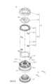
圖1係根據本發明第一實施例所繪示之成像鏡頭模組的立體示意圖。FIG1 is a three-dimensional schematic diagram of an imaging lens module according to the first embodiment of the present invention.
圖2係圖1之成像鏡頭模組的分解示意圖。Figure 2 is a schematic diagram of the exploded view of the imaging lens module in Figure 1.
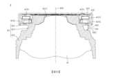
圖3係圖1之成像鏡頭模組的側面剖切示意圖。Figure 3 is a schematic side cross-sectional view of the imaging lens module in Figure 1.
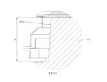
圖4係圖3之AA區域的放大示意圖。Figure 4 is an enlarged schematic diagram of the AA area in Figure 3.
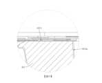
圖5係圖3之BB區域的放大示意圖。Figure 5 is an enlarged schematic diagram of the BB area in Figure 3.
圖6係圖1之成像鏡頭模組的另一側面剖切示意圖。FIG6 is another side cross-sectional view of the imaging lens module of FIG1.
圖7係根據本發明第二實施例所繪示之成像鏡頭模組的側面剖切示意圖。FIG7 is a schematic side cross-sectional view of an imaging lens module according to the second embodiment of the present invention.
圖8係根據本發明第三實施例所繪示之成像鏡頭模組的側面剖切示意圖。FIG8 is a schematic side cross-sectional view of an imaging lens module according to the third embodiment of the present invention.
圖9係根據本發明第四實施例所繪示之成像鏡頭模組的立體示意圖。FIG9 is a three-dimensional schematic diagram of an imaging lens module according to the fourth embodiment of the present invention.
圖10係圖9之成像鏡頭模組的分解示意圖。FIG10 is a schematic diagram of the exploded view of the imaging lens module of FIG9.
圖11係圖9之成像鏡頭模組的側面剖切示意圖。FIG11 is a schematic side cross-sectional view of the imaging lens module of FIG9.
圖12係圖11之CC區域的放大示意圖。Figure 12 is an enlarged schematic diagram of the CC area in Figure 11.
圖13係圖11之DD區域的放大示意圖。Figure 13 is an enlarged schematic diagram of the DD area in Figure 11.
圖14係圖9之成像鏡頭模組的另一側面剖切示意圖。FIG14 is another side cross-sectional view of the imaging lens module of FIG9 .
圖15係根據本發明第五實施例所繪示之成像鏡頭模組之透鏡載體的立體示意圖。FIG15 is a three-dimensional schematic diagram of the lens carrier of the imaging lens module according to the fifth embodiment of the present invention.
圖16係圖15之透鏡載體的側面剖切示意圖。Figure 16 is a schematic side cross-sectional view of the lens carrier of Figure 15.
圖17係根據本發明第六實施例所繪示之成像鏡頭模組之透鏡載體的立體示意圖。FIG17 is a three-dimensional schematic diagram of the lens carrier of the imaging lens module according to the sixth embodiment of the present invention.
圖18係圖17之透鏡載體的側面剖切示意圖。Figure 18 is a schematic side cross-sectional view of the lens carrier of Figure 17.
圖19繪示依照本發明第七實施例的一種電子裝置的立體示意圖。FIG19 shows a three-dimensional schematic diagram of an electronic device according to the seventh embodiment of the present invention.
圖20繪示圖19之電子裝置之另一側的立體示意圖。FIG20 is a three-dimensional schematic diagram showing another side of the electronic device of FIG19.
圖21繪示圖19之電子裝置的系統方塊圖。FIG. 21 shows a system block diagram of the electronic device of FIG. 19 .
圖22繪示圖19之電子裝置以廣視角相機模組所擷取到的影像示意圖。FIG. 22 is a schematic diagram showing an image captured by the electronic device of FIG. 19 using a wide-angle camera module.
圖23繪示圖19之電子裝置以可變光圈相機模組在光圈值為1.4的狀態所擷取到的影像示意圖。FIG. 23 is a schematic diagram showing an image captured by the electronic device of FIG. 19 using a variable aperture camera module when the aperture value is 1.4.
圖24繪示圖19之電子裝置以可變光圈相機模組在光圈值為5.6的狀態所擷取到的影像示意圖。FIG. 24 is a schematic diagram showing an image captured by the electronic device of FIG. 19 using a variable aperture camera module when the aperture value is 5.6.
以下在實施方式中詳細敘述本發明之詳細特徵以及優點,其內容足以使任何熟習相關技藝者瞭解本發明之技術內容並據以實施,且根據本說明書所揭露之內容、申請專利範圍及圖式,任何熟習相關技藝者可輕易地理解本發明相關之目的及優點。以下之實施例進一步詳細說明本發明之觀點,但非以任何觀點限制本發明之範疇。The detailed features and advantages of the present invention are described in detail in the following implementation method. The content is sufficient for anyone familiar with the relevant technology to understand the technical content of the present invention and implement it accordingly. According to the content disclosed in this specification, the scope of the patent application and the drawings, anyone familiar with the relevant technology can easily understand the relevant purposes and advantages of the present invention. The following embodiments further illustrate the viewpoints of the present invention in detail, but do not limit the scope of the present invention by any viewpoint.
本發明提供一成像鏡頭模組,包含至少一透鏡、一透鏡載體以及一可變通孔組。所述至少一透鏡具有一光軸。透鏡載體容納所述至少一透鏡。其中,透鏡載體可實體接觸於所述至少一透鏡。可變通孔組設置於透鏡載體。可變通孔組包含多個可轉動葉片。可轉動葉片可轉動地圍繞光軸設置。可轉動葉片形成一通孔,且通孔的尺寸可變。The present invention provides an imaging lens module, comprising at least one lens, a lens carrier and a variable through hole group. The at least one lens has an optical axis. The lens carrier accommodates the at least one lens. The lens carrier can physically contact the at least one lens. The variable through hole group is arranged on the lens carrier. The variable through hole group includes a plurality of rotatable blades. The rotatable blades are rotatably arranged around the optical axis. The rotatable blades form a through hole, and the size of the through hole is variable.
具體來說,透鏡載體包含一物端部、一像端部以及一管狀部。物端部供可變通孔組設置。物端部具有一物端開孔以及一導軌結構(guiding structure)。物端開孔用以供光線進入成像鏡頭模組,且物端部例如在物端開孔處具有傾斜的結構,而在傾斜結構的最窄處形成透鏡載體的一最小開孔。導軌結構引導可轉動葉片的作動,且導軌結構較最小開孔遠離光軸。像端部與物端部相對。管狀部連接物端部與像端部。Specifically, the lens carrier includes an object end, an image end, and a tubular portion. The object end is provided with a variable aperture group. The object end has an object end opening and a guiding structure. The object end opening is used to allow light to enter the imaging lens module, and the object end has a tilted structure at the object end opening, and a minimum opening of the lens carrier is formed at the narrowest part of the tilted structure. The guiding structure guides the movement of the rotatable blades, and the guiding structure is farther from the optical axis than the minimum opening. The image end is opposite to the object end. The tubular portion connects the object end and the image end.
藉由透鏡載體的結構設計,能使成像鏡頭模組具有足夠的餘裕來整合可變通孔組,並能增加應用的範圍而能適用於多種電子產品中。此外,藉由透鏡載體物側端的縮小設計,能使成像鏡頭模組適用於前端體積較小的小頭鏡頭。The structural design of the lens carrier allows the imaging lens module to have enough margin to integrate the variable aperture set, and can increase the scope of application and be applicable to a variety of electronic products. In addition, the reduced design of the object side of the lens carrier allows the imaging lens module to be applicable to small lenses with a smaller front end volume.
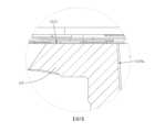
物端部更可具有一天面、至少一開槽、一第一側壁、一第二側壁以及一第三側壁。天面可為物端部最靠近物側的表面。其中,天面可在垂直於光軸的方向上延伸。所述至少一開槽可在平行於光軸的方向上遠離天面延伸。第一側壁可較導軌結構靠近光軸。第二側壁可位於所述至少一開槽,且第二側壁可較第一側壁靠近光軸。藉此,可保持成像鏡頭模組的射出成型良率。第三側壁可位於所述至少一開槽,且第三側壁可較第二側壁靠近光軸。藉此,可進一步保持成像鏡頭模組的射出成型良率。請參照圖5,係繪示有根據本發明第一實施例之天面1213。請參照圖15至圖16以及圖17至圖18,係分別繪示有根據本發明第五實施例之開槽5214a以及第六實施例之開槽6214a。請參照圖17至圖18,係繪示有根據本發明第六實施例之開槽6214b。請參照圖4,係繪示有根據本發明第一實施例之第一側壁1215a。請參照圖15至圖16以及圖17至圖18,係分別繪示有根據本發明第五實施例之第二側壁5215b以及第六實施例之第二側壁6215b。請參照圖17至圖18,係繪示有根據本發明第六實施例之第三側壁6215c。The object end portion may further have a sky surface, at least one groove, a first side wall, a second side wall and a third side wall. The sky surface may be the surface of the object end portion that is closest to the object side. The sky surface may extend in a direction perpendicular to the optical axis. The at least one groove may extend away from the sky surface in a direction parallel to the optical axis. The first side wall may be closer to the optical axis than the guide rail structure. The second side wall may be located at the at least one groove, and the second side wall may be closer to the optical axis than the first side wall. In this way, the injection molding yield of the imaging lens module may be maintained. The third side wall may be located at the at least one groove, and the third side wall may be closer to the optical axis than the second side wall. In this way, the injection molding yield of the imaging lens module may be further maintained. Please refer to FIG. 5, which shows a
物端部與像端部之間可形成一空氣夾層(air sleeve)。空氣夾層可較管狀部遠離光軸。空氣夾層可具有一空氣夾層上表面以及一空氣夾層下表面。空氣夾層上表面可為一在垂直於光軸的方向上延伸的表面,且可為空氣夾層在平行於光軸的方向上最靠近物側的表面。空氣夾層下表面可為一在垂直於光軸的方向上延伸的表面,且可為空氣夾層在平行於光軸的方向上最靠近像側的表面。其中,在平行於光軸的方向上,物端部、像端部與空氣夾層可有重疊。或者也可以說,空氣夾層上表面可為物端部的其中一個表面,而空氣夾層下表面可為像端部的其中一個表面。請參照圖3,係繪示有根據本發明第一實施例之空氣夾層AS、空氣夾層上表面AS1與空氣夾層下表面AS2。An air sleeve may be formed between the object end and the image end. The air sleeve may be farther from the optical axis than the tubular portion. The air sleeve may have an air sleeve upper surface and an air sleeve lower surface. The air sleeve upper surface may be a surface extending in a direction perpendicular to the optical axis, and may be the surface of the air sleeve closest to the object side in a direction parallel to the optical axis. The air sleeve lower surface may be a surface extending in a direction perpendicular to the optical axis, and may be the surface of the air sleeve closest to the image side in a direction parallel to the optical axis. In the direction parallel to the optical axis, the object end, the image end and the air sleeve may overlap. Alternatively, the upper surface of the air sandwich layer can be one of the surfaces of the object end, and the lower surface of the air sandwich layer can be one of the surfaces of the image end. Please refer to Figure 3, which shows the air sandwich layer AS, the upper surface AS1 of the air sandwich layer, and the lower surface AS2 of the air sandwich layer according to the first embodiment of the present invention.
可變通孔組更可包含一葉片驅動部。葉片驅動部可包含至少一驅動磁石、至少一驅動線圈、一轉動件以及至少二滾動元件(rolling member)。The variable hole group may further include a blade driving part. The blade driving part may include at least one driving magnet, at least one driving coil, a rotating member and at least two rolling members.
所述至少一驅動磁石與所述至少一驅動線圈可在平行於光軸的方向上彼此相對設置。其中,所述至少一驅動磁石可設置於所述至少一驅動線圈上方,但本發明不此為限。藉由所述至少一驅動磁石與所述至少一驅動線圈之間的相互作用,可精確控制通孔的尺寸。The at least one driving magnet and the at least one driving coil may be arranged opposite to each other in a direction parallel to the optical axis. The at least one driving magnet may be arranged above the at least one driving coil, but the present invention is not limited thereto. The size of the through hole may be precisely controlled by the interaction between the at least one driving magnet and the at least one driving coil.
轉動件可連接可轉動葉片,且轉動件可驅動可轉動葉片以調整通孔的尺寸。其中,轉動件與可轉動葉片可相對設置。藉此,可準確的控制通孔的尺寸。The rotating member can be connected to the rotatable blade, and the rotating member can drive the rotatable blade to adjust the size of the through hole. The rotating member and the rotatable blade can be arranged opposite to each other. In this way, the size of the through hole can be accurately controlled.
所述至少二滾動元件可為球狀元件,且可在平行於光軸的方向上設置於導軌結構與轉動件之間以支撐轉動件的轉動。具體來說,所述至少二滾動元件可在導軌結構與轉動件之間移動,藉以可驅動轉動件轉動,並可引導可轉動葉片作動。所述至少二滾動元件較第一側壁遠離光軸。藉此,可降低可變通孔組的高度,使得可變通孔組的最大通孔可貼近透鏡載體的最小開孔,並可使得最大通孔接近整體光學系統的初始光圈值。其中,所述至少二滾動元件可與光軸對齊。或者也可以說,所述至少二滾動元件可位在與光軸垂直的同一平面。又或者也可以說,所述至少二滾動元件可相對光軸呈軸對稱。藉此,有助於提升所述至少二滾動元件的轉動穩定性。The at least two rolling elements may be spherical elements, and may be disposed between the guide rail structure and the rotating member in a direction parallel to the optical axis to support the rotation of the rotating member. Specifically, the at least two rolling elements may move between the guide rail structure and the rotating member to drive the rotating member to rotate, and may guide the rotatable blades to move. The at least two rolling elements are farther from the optical axis than the first side wall. Thereby, the height of the variable through hole group may be lowered, so that the maximum through hole of the variable through hole group may be close to the minimum opening of the lens carrier, and the maximum through hole may be close to the initial aperture value of the entire optical system. The at least two rolling elements may be aligned with the optical axis. Alternatively, it can be said that the at least two rolling elements may be located in the same plane perpendicular to the optical axis. Alternatively, it can be said that the at least two rolling elements can be axially symmetrical relative to the optical axis. This helps to improve the rotational stability of the at least two rolling elements.
根據本發明之一實施例所揭露的成像鏡頭模組,更可包含一自動對焦驅動部。自動對焦驅動部包含至少一自動對焦磁石以及至少一自動對焦線圈。所述至少一自動對焦線圈相對所述至少一自動對焦磁石設置。所述至少一自動對焦磁石與所述至少一自動對焦線圈的其中一者設置於空氣夾層內。自動對焦驅動部驅動透鏡載體在平行於光軸的方向上移動。藉此,可進行自動對焦(Auto Focus,AF)。請參照圖7,係繪示有根據本發明第二實施例之自動對焦驅動部26及其包含的自動對焦磁石261與自動對焦線圈262。According to an embodiment of the present invention, the imaging lens module disclosed may further include an autofocus drive unit. The autofocus drive unit includes at least one autofocus magnet and at least one autofocus coil. The at least one autofocus coil is arranged relative to the at least one autofocus magnet. One of the at least one autofocus magnet and the at least one autofocus coil is arranged in an air sandwich. The autofocus drive unit drives the lens carrier to move in a direction parallel to the optical axis. Thereby, autofocus (Auto Focus, AF) can be performed. Please refer to Figure 7, which shows an
物端部在垂直於光軸的方向上的最大外徑為Do,像端部在垂直於光軸的方向上的最大外徑為Di,其可滿足下列條件:0.9

物端部在垂直於光軸的方向上的最大外徑為Do,像端部在垂直於光軸的方向上的最大外徑為Di,管狀部在垂直於光軸的方向上的最大外徑為Dt,其可滿足下列條件:4[公釐]

所述至少二滾動元件可各自具有一滾動元件中心。滾動元件中心與天面之間在平行於光軸的方向上的距離為h1,第一側壁在平行於光軸的方向上的高度為h2,其可滿足下列條件:1

第一側壁在平行於光軸的方向上的高度為h2,第二側壁的高度為h3,其可滿足下列條件:0<h3/h2
第二側壁的高度為h3,第三側壁的高度為h4,其可滿足下列條件:0<h4/h3
空氣夾層上表面與空氣夾層下表面之間在平行於光軸的方向上的距離為Ha,透鏡載體的高度為Hb,其可滿足下列條件:0.005

成像鏡頭模組的光圈值為FNO,其可滿足下列條件:1.4

成像鏡頭模組的最大視角為FOV,其可滿足下列條件:50[度]

本發明提供一種電子裝置,其包含前述的成像鏡頭模組。The present invention provides an electronic device, which includes the aforementioned imaging lens module.
上述本發明成像鏡頭模組與電子裝置中的各技術特徵皆可組合配置,而達到對應之功效。The above-mentioned imaging lens module and various technical features of the electronic device of the present invention can be configured in combination to achieve corresponding effects.
根據上述實施方式,以下提出具體實施例並配合圖式予以詳細說明。Based on the above implementation method, a specific implementation example is proposed below and described in detail with accompanying drawings.
<第一實施例><First embodiment>
請參照圖1至圖6,其中圖1係根據本發明第一實施例所繪示之成像鏡頭模組的立體示意圖,圖2係圖1之成像鏡頭模組的分解示意圖,圖3係圖1之成像鏡頭模組的側面剖切示意圖,圖4係圖3之AA區域的放大示意圖,圖5係圖3之BB區域的放大示意圖,且圖6係圖1之成像鏡頭模組的另一側面剖切示意圖。Please refer to Figures 1 to 6, wherein Figure 1 is a three-dimensional schematic diagram of an imaging lens module according to the first embodiment of the present invention, Figure 2 is an exploded schematic diagram of the imaging lens module of Figure 1, Figure 3 is a side cross-sectional schematic diagram of the imaging lens module of Figure 1, Figure 4 is an enlarged schematic diagram of the AA area of Figure 3, Figure 5 is an enlarged schematic diagram of the BB area of Figure 3, and Figure 6 is another side cross-sectional schematic diagram of the imaging lens module of Figure 1.
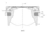
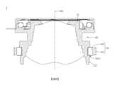
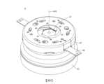
本發明第一實施例提供一種成像鏡頭模組1,包含多片透鏡11、一透鏡載體12、一可變通孔組13、一柔性電路板14以及多個磁性件15。The first embodiment of the present invention provides an
透鏡11具有一光軸110。透鏡11的數量、表面形狀和厚度等並非用以限制本發明,故未在圖式中繪示出完整的透鏡輪廓。The
透鏡載體12於內側實體接觸透鏡11,以容納透鏡11。透鏡載體12包含一物端部121、一像端部122以及一管狀部123。像端部122與物端部121相對。管狀部123連接物端部121與像端部122。The
具體來說,物端部121具有一物端開孔1211、多個導軌結構1212、一天面1213以及多個第一側壁1215a。Specifically, the
物端開孔1211用以供光線進入成像鏡頭模組1,且物端部121在物端開孔1211處形成透鏡載體12的一最小開孔OP。The
導軌結構1212較最小開孔OP遠離光軸110。The
天面1213在垂直於光軸110的方向上延伸,並作為物端部121最靠近物側的表面。更進一步來說,天面1213可為沿著垂直於光軸110的方向延伸之物端部121的外表面。The apex 1213 extends in a direction perpendicular to the
第一側壁1215a較導軌結構1212靠近光軸110。The
物端部121與像端部122之間形成一空氣夾層AS。空氣夾層AS較管狀部123遠離光軸110。空氣夾層AS具有一空氣夾層上表面AS1以及一空氣夾層下表面AS2。空氣夾層上表面AS1在垂直於光軸110的方向上延伸,且為空氣夾層AS在平行於光軸110的方向上最靠近物側的表面。空氣夾層下表面AS2在垂直於光軸110的方向上延伸,且為空氣夾層AS在平行於光軸110的方向上最靠近像側的表面。並且,在平行於光軸110的方向上,物端部121、像端部122與空氣夾層AS有重疊。An air sandwich layer AS is formed between the
可變通孔組13設置於物端部121。可變通孔組13包含一上蓋131、多個可轉動葉片132以及一葉片驅動部133。可轉動葉片132可轉動地圍繞光軸110設置於上蓋131與葉片驅動部133之間。可轉動葉片132受到導軌結構1212引導而作動。可轉動葉片132形成一通孔TH,且通孔TH的尺寸可變。The variable through hole set 13 is arranged at the
葉片驅動部133包含多個驅動磁石1331、多個驅動線圈1332、一轉動件1333以及多個滾動元件1334。The
驅動磁石1331與驅動線圈1332在平行於光軸110的方向上彼此相對設置,且驅動磁石1331設置於驅動線圈1332上方。The
轉動件1333連接可轉動葉片132並與可轉動葉片132相對設置,且轉動件1333驅動可轉動葉片132以調整通孔TH的尺寸。The rotating
滾動元件1334為球狀元件,在平行於光軸110的方向上設置於導軌結構1212與轉動件1333之間,並可在導軌結構1212與轉動件1333之間移動,以支撐轉動件1333的轉動,進而引導可轉動葉片132作動。並且,滾動元件1334較第一側壁1215a遠離光軸110,且與光軸110對齊。The rolling
柔性電路板14設置於透鏡載體12與可變通孔組13之間,以將控制訊號傳輸至驅動線圈1332。The
磁性件15設置於透鏡載體12上,以提供與驅動磁石1331作用的磁場。The
物端部121在垂直於光軸110的方向上的最大外徑為Do,像端部122在垂直於光軸110的方向上的最大外徑為Di,管狀部123在垂直於光軸110的方向上的最大外徑為Dt,其滿足下列條件:Do=12.30[公釐];Di=10.91[公釐];Dt=9.29[公釐];Do/Di=1.13;以及4[公釐]

滾動元件1334各自具有一滾動元件中心1334p。滾動元件中心1334p與天面1213之間在平行於光軸110的方向上的距離為h1,第一側壁1215a在平行於光軸110的方向上的高度為h2,其滿足下列條件:h1=0.7[公釐];h2=1.33[公釐];以及h2/h1=1.9。Each rolling
空氣夾層上表面AS1與空氣夾層下表面AS2之間在平行於光軸110的方向上的距離為Ha,透鏡載體12的高度為Hb,其滿足下列條件:Ha=1.76[公釐];Hb=6.76[公釐];以及Ha/Hb=0.26。The distance between the upper surface AS1 of the air interlayer and the lower surface AS2 of the air interlayer in the direction parallel to the
成像鏡頭模組1的光圈值為FNO,其滿足下列條件:1.4

成像鏡頭模組1的最大視角為FOV,其滿足下列條件:50[度]

<第二實施例><Second embodiment>
請參照圖7,係根據本發明第二實施例所繪示之成像鏡頭模組的側面剖切示意圖。Please refer to Figure 7, which is a side cross-sectional schematic diagram of the imaging lens module according to the second embodiment of the present invention.
本發明第二實施例提供一種成像鏡頭模組2,其類似於上述第一實施例的成像鏡頭模組1,以下僅針對成像鏡頭模組2與成像鏡頭模組1之間的相異處進行說明,且以下說明可能結合部分其他元件以便於理解。The second embodiment of the present invention provides an
成像鏡頭模組2更可包含一自動對焦驅動部26。自動對焦驅動部26包含多個自動對焦磁石261以及一自動對焦線圈262。自動對焦線圈262相對自動對焦磁石261設置。自動對焦線圈262設置於空氣夾層AS內。自動對焦驅動部26可驅動透鏡載體22在平行於光軸210的方向上移動。The
<第三實施例><Third embodiment>
請參照圖8,係根據本發明第三實施例所繪示之成像鏡頭模組的側面剖切示意圖。Please refer to Figure 8, which is a side cross-sectional schematic diagram of the imaging lens module according to the third embodiment of the present invention.
本發明第三實施例提供一種成像鏡頭模組3,其類似於上述第一實施例的成像鏡頭模組1,以下僅針對成像鏡頭模組3與成像鏡頭模組1之間的相異處進行說明,且以下說明可能結合部分其他元件以便於理解。The third embodiment of the present invention provides an
成像鏡頭模組3的像端部322具有一凹槽3221,凹槽3221較空氣夾層AS靠近像側。成像鏡頭模組3更可包含一自動對焦驅動部36。自動對焦驅動部36包含多個自動對焦磁石361以及一自動對焦線圈362。自動對焦線圈362相對自動對焦磁石361設置。自動對焦線圈362設置於凹槽3221內。自動對焦驅動部36可驅動透鏡載體32在平行於光軸310的方向上移動。The
<第四實施例><Fourth embodiment>
請參照圖9至圖14,其中圖9係根據本發明第四實施例所繪示之成像鏡頭模組的立體示意圖,圖10係圖9之成像鏡頭模組的分解示意圖,圖11係圖9之成像鏡頭模組的側面剖切示意圖,圖12係圖11之CC區域的放大示意圖,圖13係圖11之DD區域的放大示意圖,且圖14係圖9之成像鏡頭模組的另一側面剖切示意圖。Please refer to Figures 9 to 14, wherein Figure 9 is a three-dimensional schematic diagram of an imaging lens module according to the fourth embodiment of the present invention, Figure 10 is an exploded schematic diagram of the imaging lens module of Figure 9, Figure 11 is a side cross-sectional schematic diagram of the imaging lens module of Figure 9, Figure 12 is an enlarged schematic diagram of the CC area of Figure 11, Figure 13 is an enlarged schematic diagram of the DD area of Figure 11, and Figure 14 is another side cross-sectional schematic diagram of the imaging lens module of Figure 9.
本發明第四實施例提供一種成像鏡頭模組4,包含多片透鏡41、一透鏡載體42、一可變通孔組43、一柔性電路板44以及多個磁性件45。The fourth embodiment of the present invention provides an
透鏡41具有一光軸410。透鏡41的數量、表面形狀和厚度等並非用以限制本發明,故未在圖式中繪示出完整的透鏡輪廓。The
透鏡載體42於內側實體接觸透鏡41,以容納透鏡41。透鏡載體42包含一物端部421、一像端部422以及一管狀部423。像端部422與物端部421相對。管狀部423連接物端部421與像端部422。The
具體來說,物端部421具有一物端開孔4211、多個導軌結構4212、一天面4213以及多個第一側壁4215a。Specifically, the
物端開孔4211用以供光線進入成像鏡頭模組4,且物端部421在物端開孔4211處形成透鏡載體42的一最小開孔OP。The
導軌結構4212較最小開孔OP遠離光軸410。The
天面4213在垂直於光軸410的方向上延伸,並作為物端部421最靠近物側的表面。更進一步來說,天面4213可為沿著垂直於光軸410的方向延伸之物端部421的外表面。The apex 4213 extends in a direction perpendicular to the
第一側壁4215a較導軌結構4212靠近光軸410。The
物端部421與像端部422之間形成一空氣夾層AS。空氣夾層AS較管狀部423遠離光軸410。空氣夾層AS具有一空氣夾層上表面AS1以及一空氣夾層下表面AS2。空氣夾層上表面AS1在垂直於光軸410的方向上延伸,且為空氣夾層AS在平行於光軸410的方向上最靠近物側的表面。空氣夾層下表面AS2在垂直於光軸410的方向上延伸,且為空氣夾層AS在平行於光軸410的方向上最靠近像側的表面。並且,在平行於光軸410的方向上,物端部421、像端部422與空氣夾層AS有重疊。An air sandwich layer AS is formed between the
可變通孔組43設置於物端部421。可變通孔組43包含一上蓋431、多個可轉動葉片432以及一葉片驅動部433。可轉動葉片432可轉動地圍繞光軸410設置於上蓋431與葉片驅動部433之間。可轉動葉片432受到導軌結構4212引導而作動。可轉動葉片432形成一通孔TH,且通孔TH的尺寸可變。The variable through hole set 43 is arranged at the
葉片驅動部433包含多個驅動磁石4331、多個驅動線圈4332、一轉動件4333以及多個滾動元件4334。The
驅動磁石4331與驅動線圈4332在平行於光軸410的方向上彼此相對設置,且驅動磁石4331設置於驅動線圈4332上方。The
轉動件4333連接可轉動葉片432並與可轉動葉片432相對設置,且轉動件4333驅動可轉動葉片432以調整通孔TH的尺寸。The rotating
滾動元件4334為球狀元件,在平行於光軸410的方向上設置於導軌結構4212與轉動件4333之間,並可在導軌結構4212與轉動件4333之間移動,以支撐轉動件4333的轉動,進而引導可轉動葉片432作動。並且,滾動元件4334較第一側壁4215a遠離光軸410,且與光軸410對齊。The rolling
柔性電路板44設置於透鏡載體42與可變通孔組43之間,以將控制訊號傳輸至驅動線圈4332。The
磁性件45設置於透鏡載體42上,以提供與驅動磁石4331作用的磁場。The
物端部421在垂直於光軸410的方向上的最大外徑為Do,像端部422在垂直於光軸410的方向上的最大外徑為Di,管狀部423在垂直於光軸410的方向上的最大外徑為Dt,其滿足下列條件:Do=6.55[公釐];Di=6.15[公釐];Dt=4.8[公釐];Do/Di=1.07;以及4[公釐]

滾動元件4334各自具有一滾動元件中心4334p。滾動元件中心4334p與天面4213之間在平行於光軸410的方向上的距離為h1,第一側壁4215a在平行於光軸410的方向上的高度為h2,其滿足下列條件:h1=0.35[公釐];h2=0.66[公釐];以及h2/h1=1.89。Each rolling
空氣夾層上表面AS1與空氣夾層下表面AS2之間在平行於光軸410的方向上的距離為Ha,透鏡載體42的高度為Hb,其滿足下列條件:Ha=0.41[公釐];Hb=3.57[公釐];以及Ha/Hb=0.11。The distance between the upper surface AS1 of the air sandwich layer and the lower surface AS2 of the air sandwich layer in the direction parallel to the
成像鏡頭模組4的光圈值為FNO,其滿足下列條件:1.4

成像鏡頭模組4的最大視角為FOV,其滿足下列條件:50[度]

<第五實施例><Fifth embodiment>
請參照圖15與圖16,其中圖15係根據本發明第五實施例所繪示之成像鏡頭模組之透鏡載體的立體示意圖,且圖16係圖15之透鏡載體的側面剖切示意圖。Please refer to Figures 15 and 16, wherein Figure 15 is a three-dimensional schematic diagram of the lens carrier of the imaging lens module according to the fifth embodiment of the present invention, and Figure 16 is a side cross-sectional schematic diagram of the lens carrier of Figure 15.
本發明第五實施例提供一種成像鏡頭模組,其類似於上述第四實施例的成像鏡頭模組4,以下僅針對本實施例之成像鏡頭模組與成像鏡頭模組4之間的相異處進行說明,且以下說明可能結合部分其他元件以便於理解。The fifth embodiment of the present invention provides an imaging lens module, which is similar to the
在透鏡載體52中,物端部521更具有多個開槽5214a以及多個第二側壁5215b。開槽5214a在平行於透鏡51之光軸510的方向上遠離天面5213延伸。第二側壁5215b位於開槽5214a,且第二側壁5215b較第一側壁5215a靠近光軸510。In the
第一側壁5215a在平行於光軸510的方向上的高度為h2,第二側壁5215b的高度為h3,其滿足下列條件:h2=0.66[公釐];h3=0.31[公釐];以及h3/h2=0.47。The height of the
<第六實施例><Sixth Implementation Example>
請參照圖17與圖18,其中圖17係根據本發明第六實施例所繪示之成像鏡頭模組之透鏡載體的立體示意圖,且圖18係圖17之透鏡載體的側面剖切示意圖。Please refer to Figures 17 and 18, wherein Figure 17 is a three-dimensional schematic diagram of the lens carrier of the imaging lens module according to the sixth embodiment of the present invention, and Figure 18 is a side cross-sectional schematic diagram of the lens carrier of Figure 17.
本發明第六實施例提供一種成像鏡頭模組,其類似於上述第四實施例的成像鏡頭模組4,以下僅針對本實施例之成像鏡頭模組與成像鏡頭模組4之間的相異處進行說明,且以下說明可能結合部分其他元件以便於理解。The sixth embodiment of the present invention provides an imaging lens module, which is similar to the
在透鏡載體62中,物端部621更具有多個開槽6214a、6214b、多個第二側壁6215b以及多個第三側壁6215c。開槽6214b較開槽6214a靠近透鏡61的光軸610。開槽6214a、6214b在平行於光軸610的方向上遠離天面6213延伸。第二側壁6215b位於開槽6214a,且第二側壁6215b較第一側壁6215a靠近光軸610。第三側壁6215c位於開槽6214b,且第三側壁6215c較第二側壁6215b靠近光軸610。In the
第一側壁6215a在平行於光軸610的方向上的高度為h2,第二側壁6215b的高度為h3,其滿足下列條件:h2=0.66[公釐];h3=0.59[公釐];以及h3/h2=0.89。The height of the
第三側壁6215c的高度為h4,其滿足下列條件:h3=0.59[公釐];h4=0.36[公釐];以及h4/h3=0.61。The height of the
<第七實施例><Seventh Implementation Example>
請參照圖19至圖21,其中圖19繪示依照本發明第七實施例的一種電子裝置的立體示意圖,圖20繪示圖19之電子裝置之另一側的立體示意圖,且圖21繪示圖19之電子裝置的系統方塊圖。Please refer to Figures 19 to 21, wherein Figure 19 is a three-dimensional schematic diagram of an electronic device according to the seventh embodiment of the present invention, Figure 20 is a three-dimensional schematic diagram of the other side of the electronic device of Figure 19, and Figure 21 is a system block diagram of the electronic device of Figure 19.
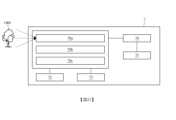
在本實施例中,電子裝置7為一行動裝置,其中行動裝置可以是電腦、智慧型手機、智慧型穿戴裝置、空拍機或車用影像紀錄與顯示儀器等等,本發明不以此為限。電子裝置7包含可變光圈相機模組70a、廣視角相機模組70b、微距相機模組70c、微型相機模組70d、飛時測距(Time of Flight,ToF)相機模組70e、閃光燈模組72、對焦輔助模組73、影像訊號處理器(Image Signal Processor)(未另標號)、顯示裝置75、影像軟體處理器(未另標號)以及生物識別感測器77。其中,可變光圈相機模組70a例如為第一實施例之成像鏡頭模組1,但本發明不以此為限。相機模組70b、70c、70d、70e亦可例如為上述本發明其他實施例的成像鏡頭模組。In this embodiment, the
相機模組70a、相機模組70b及相機模組70c係皆配置於電子裝置7的同一側。相機模組70d、相機模組70e及顯示裝置75係皆配置於電子裝置7的另一側,並且顯示裝置75可為使用者介面,以使相機模組70d及相機模組70e可作為前置鏡頭以提供自拍功能,但本發明並不以此為限。
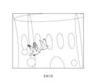
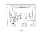
本實施例之相機模組70a、相機模組70b及相機模組70c具有相異的視角,使電子裝置7可提供不同的放大倍率,以達到光學變焦的拍攝效果。舉例來說,廣視角相機模組70b具有較廣的最大視角,其所拍攝到的影像可參照圖22,係繪示有電子裝置7以廣視角相機模組70b所擷取到的影像示意圖,其中所擷取到的影像包含整體教堂、周邊建築與廣場上的人物。圖22的影像具有較大的視角與景深,但常伴隨有較大的畸變。可變光圈相機模組70a在較小光圈值時所拍攝到的影像可參照圖23,而在較大光圈值時所拍攝到的影像可參照圖24。圖23係繪示有電子裝置7以可變光圈相機模組70a在光圈值為1.4的狀態所擷取到的影像示意圖,且圖24係繪示有電子裝置7以可變光圈相機模組70a在光圈值為5.6的狀態所擷取到的影像示意圖,其中所擷取到的影像包含教堂前方飛翔的鳥群。如圖23所示,當可變光圈相機模組70a的可變通孔組提供較大的通孔時,電子感光元件獲得較多的光線,但此時背景較模糊不清。如圖24所示,當可變光圈相機模組70a的可變通孔組提供較小的通孔時,電子感光元件獲得較少的光線,但可獲得較清楚的背景。圖23和圖24的影像具有較小的視角,使得可變光圈相機模組70a可用於拍攝移動目標,自動對焦驅動部驅動透鏡載體對目標快速且連續的自動對焦,使目標物不會因為遠離對焦位置而模糊不清;在取像時,可變光圈相機模組70a可進一步針對拍攝主題進行光學變焦,獲得更清晰的影像。另外,飛時測距相機模組70e係可取得影像的深度資訊。上述電子裝置7以包含多個相機模組70a、70b、70c、70d、70e為例,但相機模組的數量與配置並非用以限制本發明。The
當使用者拍攝被攝物OBJ時,電子裝置7利用相機模組70a、相機模組70b或相機模組70c聚光取像,啟動閃光燈模組72進行補光,並使用對焦輔助模組73提供的被攝物OBJ之物距資訊進行快速對焦,再加上影像訊號處理器進行影像最佳化處理,來進一步提升透鏡組所產生的影像品質。對焦輔助模組73可採用紅外線或雷射對焦輔助系統來達到快速對焦。When the user takes a photo of the object OBJ, the
此外,電子裝置7亦可利用相機模組70d或相機模組70e進行拍攝。當相機模組70d或相機模組70e進行拍攝時,可有一提示燈7a發光以提醒使用者電子裝置7正在拍攝中。顯示裝置75可採用觸控螢幕或變焦控制鍵751和對焦拍照按鍵752之實體的拍攝按鈕,配合影像軟體處理器的多樣化功能進行影像拍攝以及影像處理。經由影像軟體處理器處理後的影像可顯示於顯示裝置75。使用者還可透過顯示裝置75的影像回放按鍵753重播先前拍攝的影像,亦可透過相機模組切換按鍵754以選取適合的相機模組來進行拍攝,還可透過集成選單按鍵755來對當下的拍攝場景進行適合的拍攝條件調整。In addition, the
進一步來說,電子裝置7更包含一電路板78,且電路板78承載多個電子元件79。相機模組70a、70b、70c、70d、70e透過電路板78上的連結器781電性連接電子元件79,其中電子元件79可包含一訊號發射模組,可透過訊號發射模組將影像傳遞至其他電子裝置或是雲端儲存。其中,訊號發射模組可以是無線網路技術(Wireless Fidelity,WiFi)模組、藍牙模組、紅外線模組、網路服務模組或上述多種訊號發射的集成模組,本發明不以此為限。Furthermore, the
電子元件79亦可包含儲存單元、隨機存取記憶體以儲存影像訊號、陀螺儀、位置定位器以利電子裝置7的導航或定位。在本實施例中,影像訊號處理器、影像軟體處理器與隨機存取記憶體整合成一個單晶片系統74,但本發明不以此配置為限。在部分其他實施例中,電子元件亦可以整合於相機模組或亦可設置於多個電路板的其中一者。此外,生物識別感測器77可提供電子裝置7開機和解鎖等功能。The
本發明的成像鏡頭模組不以應用於智慧型手機為限。成像鏡頭模組更可視需求應用於移動對焦的系統,並兼具優良像差修正與良好成像品質的特色。舉例來說,成像鏡頭模組可多方面應用於三維(3D)影像擷取、數位相機、行動裝置、數位平板、智慧型電視、網路監控設備、行車記錄器、倒車顯影裝置、多鏡頭裝置、辨識系統、體感遊戲機與穿戴式裝置等電子裝置中。前揭電子裝置僅是示範性地說明本發明的實際運用例子,並非限制本發明之成像鏡頭模組的運用範圍。The imaging lens module of the present invention is not limited to being applied to smart phones. The imaging lens module can be applied to the mobile focus system according to the needs, and has the characteristics of excellent aberration correction and good imaging quality. For example, the imaging lens module can be used in many aspects in electronic devices such as three-dimensional (3D) image capture, digital cameras, mobile devices, digital tablets, smart TVs, network monitoring equipment, dash cams, reversing display devices, multi-lens devices, identification systems, somatosensory game consoles and wearable devices. The above-mentioned electronic devices are only examples of the actual application of the present invention, and do not limit the scope of application of the imaging lens module of the present invention.
雖然本發明以前述之諸項實施例揭露如上,然其並非用以限定本發明,任何熟習相像技藝者,在不脫離本發明之精神和範圍內,當可作些許之更動與潤飾,因此本發明之專利保護範圍須視本說明書所附之申請專利範圍所界定者為準。Although the present invention is disclosed as above by the aforementioned embodiments, they are not used to limit the present invention. Anyone familiar with similar techniques can make some changes and modifications without departing from the spirit and scope of the present invention. Therefore, the scope of patent protection of the present invention shall be subject to the scope of the patent application attached to this specification.
1:成像鏡頭模組1: Imaging lens module
11:透鏡11: Lens
110:光軸110:Optical axis
12:透鏡載體12: Lens carrier
121:物端部121: End of object
1211:物端開孔1211: Object end opening
1212:導軌結構1212: Rail structure
1213:天面1213:Sky face
1215a:第一側壁1215a: First side wall
122:像端部122: Like the end
123:管狀部123: Tubular part
131:上蓋131: Upper cover
132:可轉動葉片132: Rotatable blades
1333:轉動件1333: Rotating parts
1334:滾動元件1334: Rolling element
1334p:滾動元件中心1334p: Rolling element center
AA、BB:區域AA, BB: Region
AS:空氣夾層AS: Air interlayer
AS1:空氣夾層上表面AS1: Upper surface of air sandwich layer
AS2:空氣夾層下表面AS2: Air sandwich lower surface
OP:最小開孔OP: minimum opening
Ha:空氣夾層上表面與空氣夾層下表面之間在平行於光軸的方向上的距離Ha: The distance between the upper surface of the air sandwich layer and the lower surface of the air sandwich layer in the direction parallel to the optical axis
Hb:透鏡載體的高度Hb: Height of lens carrier
Di:像端部在垂直於光軸的方向上的最大外徑Di: The maximum outer diameter of the image end in the direction perpendicular to the optical axis
Do:物端部在垂直於光軸的方向上的最大外徑Do: The maximum outer diameter of the object end in the direction perpendicular to the optical axis
Dt:管狀部在垂直於光軸的方向上的最大外徑Dt: Maximum outer diameter of the tubular portion in the direction perpendicular to the optical axis
h1:滾動元件中心與天面之間在平行於光軸的方向上的距離h1: The distance between the center of the rolling element and the celestial disk in the direction parallel to the optical axis
h2:第一側壁在平行於光軸的方向上的高度h2: Height of the first side wall in the direction parallel to the optical axis
Claims (30)
Translated fromChineseApplications Claiming Priority (2)
| Application Number | Priority Date | Filing Date | Title |
|---|---|---|---|
| US202363440057P | 2023-01-19 | 2023-01-19 | |
| US63/440,057 | 2023-01-19 |
Publications (2)
| Publication Number | Publication Date |
|---|---|
| TW202431002A TW202431002A (en) | 2024-08-01 |
| TWI884414Btrue TWI884414B (en) | 2025-05-21 |
Family
ID=85795348
Family Applications (1)
| Application Number | Title | Priority Date | Filing Date |
|---|---|---|---|
| TW112103781ATWI884414B (en) | 2023-01-19 | 2023-02-03 | Imaging lens module and electric device |
Country Status (4)
| Country | Link |
|---|---|
| US (1) | US20240248373A1 (en) |
| EP (1) | EP4403993A1 (en) |
| CN (2) | CN219552740U (en) |
| TW (1) | TWI884414B (en) |
Families Citing this family (1)
| Publication number | Priority date | Publication date | Assignee | Title |
|---|---|---|---|---|
| CN119717362A (en)* | 2023-09-28 | 2025-03-28 | 大立光电股份有限公司 | Iris aperture set, optical lens module, camera module and electronic device |
Citations (9)
| Publication number | Priority date | Publication date | Assignee | Title |
|---|---|---|---|---|
| CN204389774U (en)* | 2015-02-26 | 2015-06-10 | 大立光电股份有限公司 | Camera Modules and Electronics |
| TW201626022A (en)* | 2014-12-26 | 2016-07-16 | 三美電機股份有限公司 | Lens drive unit, camera module, and camera mount device |
| JP6238762B2 (en)* | 2014-01-21 | 2017-11-29 | キヤノン株式会社 | Optical equipment |
| TW201833616A (en)* | 2017-03-08 | 2018-09-16 | 大陸商光寶電子(廣州)有限公司 | Lens module |
| TW201910894A (en)* | 2017-07-26 | 2019-03-16 | 日商日本電產三協股份有限公司 | Optical unit with shake correction |
| TW201913146A (en)* | 2017-09-01 | 2019-04-01 | 美商康寧公司 | Liquid lenses |
| JP6584070B2 (en)* | 2014-12-17 | 2019-10-02 | キヤノン株式会社 | Lens barrel and optical equipment |
| US20190373145A1 (en)* | 2018-06-05 | 2019-12-05 | Samsung Electronics Co., Ltd. | Camera module for controlling iris diaphragm using signal corrected according to position of lens assembly, electronic device including the camera module, and method for operating the electronic device |
| WO2020124553A1 (en)* | 2018-12-21 | 2020-06-25 | Huawei Technologies Co., Ltd. | Variable aperture device and camera module |
Family Cites Families (7)
| Publication number | Priority date | Publication date | Assignee | Title |
|---|---|---|---|---|
| CN201167259Y (en)* | 2008-02-18 | 2008-12-17 | 惠州市百宏微动技术工业有限公司 | Fore-and-aft support for subminiaturisation voice coil motor |
| TWI695217B (en)* | 2019-06-25 | 2020-06-01 | 大陽科技股份有限公司 | Imaging lens module and electronic device |
| US12001074B2 (en)* | 2019-10-09 | 2024-06-04 | Tdk Taiwan Corp. | Optical element driving mechanism |
| CN114125204B (en)* | 2020-08-28 | 2024-05-14 | 宁波舜宇光电信息有限公司 | Optical lens, preparation method thereof, camera module and electronic equipment |
| CN216700119U (en)* | 2021-12-25 | 2022-06-07 | Oppo广东移动通信有限公司 | Electronic equipment, camera module, motor device and its coil carrier |
| TWI836408B (en)* | 2022-04-22 | 2024-03-21 | 大立光電股份有限公司 | Imaging lens, camera module and electronic device |
| TWI833383B (en)* | 2022-09-22 | 2024-02-21 | 大立光電股份有限公司 | Variable aperture module, imaging lens module and electronic device |
- 2023
- 2023-02-03TWTW112103781Apatent/TWI884414B/enactive
- 2023-03-16CNCN202320516865.8Upatent/CN219552740U/enactiveActive
- 2023-03-16CNCN202310256787.7Apatent/CN118363131A/enactivePending
- 2023-03-31EPEP23165872.5Apatent/EP4403993A1/enactivePending
- 2023-04-19USUS18/136,771patent/US20240248373A1/enactivePending
Patent Citations (9)
| Publication number | Priority date | Publication date | Assignee | Title |
|---|---|---|---|---|
| JP6238762B2 (en)* | 2014-01-21 | 2017-11-29 | キヤノン株式会社 | Optical equipment |
| JP6584070B2 (en)* | 2014-12-17 | 2019-10-02 | キヤノン株式会社 | Lens barrel and optical equipment |
| TW201626022A (en)* | 2014-12-26 | 2016-07-16 | 三美電機股份有限公司 | Lens drive unit, camera module, and camera mount device |
| CN204389774U (en)* | 2015-02-26 | 2015-06-10 | 大立光电股份有限公司 | Camera Modules and Electronics |
| TW201833616A (en)* | 2017-03-08 | 2018-09-16 | 大陸商光寶電子(廣州)有限公司 | Lens module |
| TW201910894A (en)* | 2017-07-26 | 2019-03-16 | 日商日本電產三協股份有限公司 | Optical unit with shake correction |
| TW201913146A (en)* | 2017-09-01 | 2019-04-01 | 美商康寧公司 | Liquid lenses |
| US20190373145A1 (en)* | 2018-06-05 | 2019-12-05 | Samsung Electronics Co., Ltd. | Camera module for controlling iris diaphragm using signal corrected according to position of lens assembly, electronic device including the camera module, and method for operating the electronic device |
| WO2020124553A1 (en)* | 2018-12-21 | 2020-06-25 | Huawei Technologies Co., Ltd. | Variable aperture device and camera module |
Also Published As
| Publication number | Publication date |
|---|---|
| CN118363131A (en) | 2024-07-19 |
| CN219552740U (en) | 2023-08-18 |
| EP4403993A1 (en) | 2024-07-24 |
| US20240248373A1 (en) | 2024-07-25 |
| TW202431002A (en) | 2024-08-01 |
Similar Documents
| Publication | Publication Date | Title |
|---|---|---|
| TWI836408B (en) | Imaging lens, camera module and electronic device | |
| CN212364777U (en) | Reflection module capable of achieving image stabilization, camera module and electronic device | |
| TWI804212B (en) | Controllable aperture stop, compact camera module and electronic device | |
| TWI793978B (en) | Photographing module and electronic device | |
| TWI741790B (en) | Imaging lens system, image capturing unit and electronic device | |
| TWI761058B (en) | Lens driving module, photographing camera and electronic device | |
| TW202113415A (en) | Imaging lens, camera module and electronic device | |
| TWI814457B (en) | Light pass aperture module, camera module and electronic device | |
| CN114488460A (en) | Drivers, imaging devices and electronic devices | |
| TWI884414B (en) | Imaging lens module and electric device | |
| CN216561329U (en) | Camera Modules, Electronics and Vehicle Tools | |
| TWI882446B (en) | Camera module and electronic device | |
| TWI772185B (en) | Imaging lens driving module and electronic device | |
| CN221572982U (en) | Imaging lens module with changeable light hole module, camera module and electronic device | |
| TWI850042B (en) | Adjustable aperture module, imaging lens module, camera module and electronic device | |
| TWI898291B (en) | Adjustable aperture module, imaging lens module, camera module and electronic device | |
| TWI865085B (en) | Optical lens module and electronic device | |
| BR102023027032A2 (en) | IMAGE PROCESSING LENS MODULE AND ELECTRONIC DEVICE | |
| CN117097975A (en) | Camera module, processing method and electronic equipment |