TWI873879B - Synchronous rectifier device for power converter - Google Patents
Synchronous rectifier device for power converterDownload PDFInfo
- Publication number
- TWI873879B TWI873879BTW112137135ATW112137135ATWI873879BTW I873879 BTWI873879 BTW I873879BTW 112137135 ATW112137135 ATW 112137135ATW 112137135 ATW112137135 ATW 112137135ATW I873879 BTWI873879 BTW I873879B
- Authority
- TW
- Taiwan
- Prior art keywords
- synchronous rectification
- current
- circuit
- value
- signal
- Prior art date
Links
Images


Classifications
- H—ELECTRICITY
- H02—GENERATION; CONVERSION OR DISTRIBUTION OF ELECTRIC POWER
- H02M—APPARATUS FOR CONVERSION BETWEEN AC AND AC, BETWEEN AC AND DC, OR BETWEEN DC AND DC, AND FOR USE WITH MAINS OR SIMILAR POWER SUPPLY SYSTEMS; CONVERSION OF DC OR AC INPUT POWER INTO SURGE OUTPUT POWER; CONTROL OR REGULATION THEREOF
- H02M3/00—Conversion of DC power input into DC power output
- H02M3/22—Conversion of DC power input into DC power output with intermediate conversion into AC
- H02M3/24—Conversion of DC power input into DC power output with intermediate conversion into AC by static converters
- H02M3/28—Conversion of DC power input into DC power output with intermediate conversion into AC by static converters using discharge tubes with control electrode or semiconductor devices with control electrode to produce the intermediate AC
- H02M3/325—Conversion of DC power input into DC power output with intermediate conversion into AC by static converters using discharge tubes with control electrode or semiconductor devices with control electrode to produce the intermediate AC using devices of a triode or a transistor type requiring continuous application of a control signal
- H02M3/335—Conversion of DC power input into DC power output with intermediate conversion into AC by static converters using discharge tubes with control electrode or semiconductor devices with control electrode to produce the intermediate AC using devices of a triode or a transistor type requiring continuous application of a control signal using semiconductor devices only
- H02M3/33569—Conversion of DC power input into DC power output with intermediate conversion into AC by static converters using discharge tubes with control electrode or semiconductor devices with control electrode to produce the intermediate AC using devices of a triode or a transistor type requiring continuous application of a control signal using semiconductor devices only having several active switching elements
- H02M3/33576—Conversion of DC power input into DC power output with intermediate conversion into AC by static converters using discharge tubes with control electrode or semiconductor devices with control electrode to produce the intermediate AC using devices of a triode or a transistor type requiring continuous application of a control signal using semiconductor devices only having several active switching elements having at least one active switching element at the secondary side of an isolation transformer
- H02M3/33592—Conversion of DC power input into DC power output with intermediate conversion into AC by static converters using discharge tubes with control electrode or semiconductor devices with control electrode to produce the intermediate AC using devices of a triode or a transistor type requiring continuous application of a control signal using semiconductor devices only having several active switching elements having at least one active switching element at the secondary side of an isolation transformer having a synchronous rectifier circuit or a synchronous freewheeling circuit at the secondary side of an isolation transformer
- H—ELECTRICITY
- H02—GENERATION; CONVERSION OR DISTRIBUTION OF ELECTRIC POWER
- H02M—APPARATUS FOR CONVERSION BETWEEN AC AND AC, BETWEEN AC AND DC, OR BETWEEN DC AND DC, AND FOR USE WITH MAINS OR SIMILAR POWER SUPPLY SYSTEMS; CONVERSION OF DC OR AC INPUT POWER INTO SURGE OUTPUT POWER; CONTROL OR REGULATION THEREOF
- H02M1/00—Details of apparatus for conversion
- H02M1/0003—Details of control, feedback or regulation circuits
- H02M1/0009—Devices or circuits for detecting current in a converter
- H—ELECTRICITY
- H02—GENERATION; CONVERSION OR DISTRIBUTION OF ELECTRIC POWER
- H02M—APPARATUS FOR CONVERSION BETWEEN AC AND AC, BETWEEN AC AND DC, OR BETWEEN DC AND DC, AND FOR USE WITH MAINS OR SIMILAR POWER SUPPLY SYSTEMS; CONVERSION OF DC OR AC INPUT POWER INTO SURGE OUTPUT POWER; CONTROL OR REGULATION THEREOF
- H02M1/00—Details of apparatus for conversion
- H02M1/32—Means for protecting converters other than automatic disconnection
- Y—GENERAL TAGGING OF NEW TECHNOLOGICAL DEVELOPMENTS; GENERAL TAGGING OF CROSS-SECTIONAL TECHNOLOGIES SPANNING OVER SEVERAL SECTIONS OF THE IPC; TECHNICAL SUBJECTS COVERED BY FORMER USPC CROSS-REFERENCE ART COLLECTIONS [XRACs] AND DIGESTS
- Y02—TECHNOLOGIES OR APPLICATIONS FOR MITIGATION OR ADAPTATION AGAINST CLIMATE CHANGE
- Y02B—CLIMATE CHANGE MITIGATION TECHNOLOGIES RELATED TO BUILDINGS, e.g. HOUSING, HOUSE APPLIANCES OR RELATED END-USER APPLICATIONS
- Y02B70/00—Technologies for an efficient end-user side electric power management and consumption
- Y02B70/10—Technologies improving the efficiency by using switched-mode power supplies [SMPS], i.e. efficient power electronics conversion e.g. power factor correction or reduction of losses in power supplies or efficient standby modes
Landscapes
- Engineering & Computer Science (AREA)
- Power Engineering (AREA)
- Rectifiers (AREA)
Abstract
Description
Translated fromChinese本發明是有關於一種電子裝置,且特別是有關於一種用於電源轉換器的同步整流裝置。The present invention relates to an electronic device, and in particular to a synchronous rectification device for a power converter.
一般來說,電源轉換器可利用同步整流開關來進行同步整流操作以降低電源轉換的能量損失。同步整流開關必須基於控制信號來運行。因此,如何提供正確的控制信號來精準進行電源轉換器的同步整流操作,是本領域技術人員的研究重點之一。Generally speaking, a power converter can use a synchronous rectification switch to perform synchronous rectification operation to reduce energy loss in power conversion. The synchronous rectification switch must operate based on a control signal. Therefore, how to provide a correct control signal to accurately perform synchronous rectification operation of the power converter is one of the research focuses of technicians in this field.
本發明提供一種用於電源轉換器的同步整流裝置,能夠精準進行電源轉換器的同步整流操作。The present invention provides a synchronous rectification device for a power converter, which can accurately perform the synchronous rectification operation of the power converter.
本發明的同步整流裝置用於電源轉換器。電源轉換器至少包括二次側電路以及變壓器。同步整流裝置包括同步整流電路以及控制器。同步整流電路包括同步整流開關以及電流接收電路。同步整流開關耦接於二次側電路與變壓器的二次側繞組之間。電流接收電路接收流經同步整流開關的電流,並依據電流提供電流信號。控制器耦接於電流接收電路以及同步整流開關的控制端。控制器依據電流信號來控制同步整流開關。在同步整流開關被斷開的情況下,當電流信號表示出電流大於預定值時,控制器導通同步整流開關。The synchronous rectification device of the present invention is used for a power converter. The power converter includes at least a secondary circuit and a transformer. The synchronous rectification device includes a synchronous rectification circuit and a controller. The synchronous rectification circuit includes a synchronous rectification switch and a current receiving circuit. The synchronous rectification switch is coupled between the secondary circuit and the secondary winding of the transformer. The current receiving circuit receives the current flowing through the synchronous rectification switch and provides a current signal according to the current. The controller is coupled to the current receiving circuit and the control end of the synchronous rectification switch. The controller controls the synchronous rectification switch according to the current signal. When the synchronous rectification switch is disconnected, when the current signal indicates that the current is greater than a predetermined value, the controller turns on the synchronous rectification switch.
基於上述,電流接收電路依據流經同步整流開關的電流提供電流信號。控制器依據電流信號來控制同步整流開關。在同步整流開關被斷開的情況下,當電流信號表示出電流大於預定值時,控制器導通同步整流開關。如此一來,同步整流裝置能夠精準進行電源轉換器的同步整流操作。Based on the above, the current receiving circuit provides a current signal according to the current flowing through the synchronous rectification switch. The controller controls the synchronous rectification switch according to the current signal. When the synchronous rectification switch is disconnected, when the current signal indicates that the current is greater than a predetermined value, the controller turns on the synchronous rectification switch. In this way, the synchronous rectification device can accurately perform the synchronous rectification operation of the power converter.
10、20、30:電源轉換器10, 20, 30: Power converter
11:一次側電路11: Primary side circuit
12:變壓器12: Transformer
13:二次側電路13: Secondary circuit
100、200、300:同步整流裝置100, 200, 300: Synchronous rectification device
110:同步整流電路110: Synchronous rectification circuit
111:同步整流開關111: Synchronous rectification switch
112:電流接收電路112: Current receiving circuit
120、220、320:控制器120, 220, 320: controller
221、321:邏輯控制電路221, 321: Logic control circuit
222、322:電壓判斷電路222, 322: Voltage determination circuit
323:感測電路323: Sensing circuit
C0:輸出電容器C0: output capacitor
FF:正反器FF: Flip-flop
ID:電流ID: Current
ND:連接節點ND: Connection Node
Q:正反器的輸出端Q: Output end of the flip-flop
R:正反器的重置端R: reset terminal of the flip-flop
S:正反器的設定端S: Setting terminal of the flip-flop
SC:控制信號SC: control signal
SCR:電流信號SCR: current signal
SD:判斷信號SD: judgment signal
SS:感測信號SS: Sensing signal
TD:預定值TD: Determined value
VD:偵測電壓VD: Detection voltage
VTH:電壓閾值VTH: voltage threshold
圖1是依據本發明第一實施例所繪示的電源轉換器的示意圖。FIG1 is a schematic diagram of a power converter according to the first embodiment of the present invention.
圖2是依據本發明第二實施例所繪示的電源轉換器的示意圖。FIG2 is a schematic diagram of a power converter according to the second embodiment of the present invention.
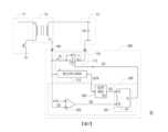
圖3是依據本發明第三實施例所繪示的電源轉換器的示意圖。FIG3 is a schematic diagram of a power converter according to the third embodiment of the present invention.
本發明的部份實施例接下來將會配合附圖來詳細描述,以下的描述所引用的元件符號,當不同附圖出現相同的元件符號將視為相同或相似的元件。這些實施例只是本發明的一部份,並未揭示所有本發明的可實施方式。更確切的說,這些實施例只是本發明的專利申請範圍中的範例。Some embodiments of the present invention will be described in detail with reference to the accompanying drawings. The component symbols cited in the following description will be regarded as the same or similar components when the same component symbols appear in different drawings. These embodiments are only part of the present invention and do not disclose all possible implementation methods of the present invention. More precisely, these embodiments are only examples within the scope of the patent application of the present invention.
請參考圖1,圖1是依據本發明第一實施例所繪示的電源轉換器的示意圖。在本實施例中,電源轉換器10包括一次側電路11、變壓器12、二次側電路13以及同步整流裝置100。以本實施例為例,變壓器12的一次側繞組耦接於一次側電路11。變壓器12的二次側繞組耦接於二次側電路13。二次側電路13包括輸出電容器C0。以本實施例為例,輸出電容器C0的第一端耦接於變壓器12的二次側繞組的第一端。輸出電容器C0的第二端耦接於二次側電路13的接地端。Please refer to FIG. 1, which is a schematic diagram of a power converter according to the first embodiment of the present invention. In this embodiment, the
在本實施例中,同步整流裝置100用於電源轉換器10的同步整流操作。同步整流裝置100包括同步整流電路110以及控制器120。同步整流電路110包括同步整流開關111以及電流接收電路112。同步整流開關111耦接於二次側電路13與變壓器12的二次側繞組之間。以本實施例為例,同步整流開關111的第一端與二次側繞組耦接於連接節點ND。同步整流開關111的第二端耦接於輸出電容器C0的第二端。同步整流開關111的控制端耦接於控制器120。In this embodiment, the
在本實施例中,電流接收電路112接收流經同步整流開關111的電流ID,並依據電流ID提供來電流信號SCR。在一實施例中,電流接收電路112可接收流經同步整流開關111的二極體元件的電流ID。在一實施例中,電流接收電路112可感應流經同步整流開關111的第一端的電流ID。電流信號SCR可以是對應於電流ID的資訊,所述資訊例如是電流ID的電流值。In this embodiment, the
在本實施例中,控制器120耦接於電流接收電路112以及同步整流開關111的控制端。控制器120接收電流信號SCR並對電流信號SCR進行分析。控制器120依據電流信號SCR來控制同步整流開關111。在同步整流開關111被斷開的情況下,當電流信號SCR表示出電流ID的電流值大於預定值TD時,控制器120導通同步整流開關111。在本實施例中,控制器120會利用控制信號SC來導通同步整流開關111。In this embodiment, the
在另一方面,在同步整流開關111被斷開的情況下,當所述電流信號SCR表示出電流ID的電流值小於或等於預定值TD時,控制器120持續斷開同步整流開關111。On the other hand, when the
在此值得一提的是,電流接收電路112依據流經同步整流開關111的電流ID來提供電流信號SCR。在同步整流開關111被斷開的情況下,當電流信號SCR表示出電流ID的電流值大於預定值TD時,控制器120導通同步整流開關111。如此一來,同步整流裝置100能夠依據流經同步整流開關111的電流ID來精準進行電源轉換器10的同步整流操作。It is worth mentioning here that the
舉例來說,在同步整流開關111被斷開的情況下,電流ID會流經同步整流開關111的二極體元件。當電流ID的電流值小於或等於預定值TD時,這表示電流ID是諧振電流。因此,控制器120持續斷開同步整流開關111。當電流ID的電流值大於預定值TD時,這表示電流ID是輸出電流,而不是諧振電流。因此,控制器120導通同步整流開關111。For example, when the
在本實施例中,控制器120可接收位於連接節點ND的偵測電壓VD,並判斷偵測電壓VD的電壓值。當偵測電壓VD的電壓值變化大於轉換率(slew rate)閾值時,控制器120會導通同步整流開關111。當偵測電壓VD的電壓值變化小於轉換率閾值時,偵測電壓VD可能是諧振電壓。因此,控制器120會持續斷開同步整流開關111。In this embodiment, the
此外,當偵測電壓VD的電壓值低於預定電壓值時,控制器120會導通同步整流開關111。當偵測電壓VD的電壓值高於或等於預定電壓值時,控制器120斷開同步整流開關111。In addition, when the voltage value of the detection voltage VD is lower than the predetermined voltage value, the
基於上述,控制器120可利用偵測電壓VD來作為控制同步整流開關111的輔助依據。然本發明並不以此為限,在一些實施例中,控制器120可以不接收偵測電壓VD。Based on the above, the
在本實施例中,同步整流開關111以及電流接收電路112被製作在單一半導體晶粒(semiconductor die)中。換言之,同步整流電路110製作在單一半導體晶粒中。控制器120以及半導體晶粒被封裝在同一電路封包(package)中。因此,同步整流裝置100能夠被組裝到電源轉換器10中。In this embodiment, the
請參考圖2,圖2是依據本發明第二實施例所繪示的電源轉換器的示意圖。在本實施例中,電源轉換器20包括一次側電路11、變壓器12、二次側電路13以及同步整流裝置200。同步整流裝置200包括同步整流電路110以及控制器220。一次側電路11、變壓器12、二次側電路13以及同步整流電路110之間的耦接關係以及同步整流電路110的實施方式已經在圖1的實施例中清楚描述,故不在此重述。Please refer to FIG. 2, which is a schematic diagram of a power converter according to the second embodiment of the present invention. In this embodiment, the
在本實施例中,控制器220耦接於電流接收電路112以及同步整流開關111的控制端。控制器220包括邏輯控制電路221。邏輯控制電路221耦接於電流接收電路112。邏輯控制電路221依據電流信號SCR來提供用於控制同步整流開關111的控制信號SC。In this embodiment, the
在同步整流開關111被斷開的情況下,當電流信號SCR表示出電流ID的電流值大於預定值TD時,邏輯控制電路221利用控制信號SC來導通同步整流開關111。在另一方面,在同步整流開關111被斷開的情況下,當所述電流信號SCR表示出電流ID的電流值小於或等於預定值TD時,邏輯控制電路221持續斷開同步整流開關111。When the
在本實施例中,控制器220還包括電壓判斷電路222。電壓判斷電路222耦接於連接節點ND以及邏輯控制電路221。電壓判斷電路222對位於連接節點ND的偵測電壓VD進行判斷以產生判斷信號SD,並將判斷信號SD提供至邏輯控制電路221。In this embodiment, the
在本實施例中,電壓判斷電路222可以是由比較器來實施。電壓判斷電路222的非反相輸入端接收偵測電壓VD。電壓判斷電路222的反相輸入端接收電壓閾值VTH。當偵測電壓VD的電壓值高於電壓閾值VTH時,電壓判斷電路222提供具有第一邏輯值的判斷信號SD。邏輯控制電路221會依據具有第一邏輯值的判斷信號SD來持續斷開同步整流開關111。當偵測電壓VD的電壓值低於或等於電壓閾值VTH時,電壓判斷電路222提供具有第二邏輯值的判斷信號SD。邏輯控制電路221會依據具有第二邏輯值的判斷信號SD來導通同步整流開關111。In this embodiment, the
請參考圖3,圖3是依據本發明第三實施例所繪示的電源轉換器的示意圖。在本實施例中,在本實施例中,電源轉換器30包括一次側電路11、變壓器12、二次側電路13以及同步整流裝置300。同步整流裝置300包括同步整流電路110以及控制器320。一次側電路11、變壓器12、二次側電路13以及同步整流電路110之間的耦接關係以及同步整流電路110的實施方式已經在圖1的實施例中清楚描述,故不在此重述。Please refer to FIG. 3, which is a schematic diagram of a power converter according to the third embodiment of the present invention. In this embodiment, the
在本實施例中,控制器320耦接於電流接收電路112以及同步整流開關111的控制端。控制器320包括邏輯控制電路321、電壓判斷電路322以及感測電路323。In this embodiment, the
在本實施例中,感測電路323耦接於電流接收電路112以及邏輯控制電路321。感測電路323依據來自於電流接收電路112的電流信號SCR來產生感測信號SS,並將感測信號SS提供至邏輯控制電路321。在本實施例中,邏輯控制電路221包括正反器FF。正反器FF的設定端S耦接於感測電路323。正反器FF的重置端R耦接於電壓判斷電路322。正反器FF的輸出端Q耦接於所述同步整流開關111的控制端。In this embodiment, the
在本實施例中,感測電路323對電流ID的電流值進行判斷。當電流ID的電流值高於預定值TD時,感測電路323產生具有高邏輯值的感測信號SS。在另一方面,當電流ID的電流值低於或等於預定值TD時,感測電路323則產生具有低邏輯值的感測信號SS。In this embodiment, the
此外,當偵測電壓VD的電壓值高於電壓閾值VTH時,電壓判斷電路322提供具有高邏輯值的判斷信號SD。在另一方面,當偵測電壓VD的電壓值低於或等於電壓閾值VTH時,電壓判斷電路322提供具有低邏輯值的判斷信號SD。In addition, when the voltage value of the detection voltage VD is higher than the voltage threshold value VTH, the
在本實施例中,當偵測電壓VD的電壓值低於或等於電壓閾值VTH並且電流ID的電流值高於預定值TD時,正反器FF會輸出控制信號SC(即,具有高邏輯值的信號)來導通同步整流開關111。當偵測電壓VD的電壓值高於電壓閾值VTH時,正反器FF會斷開同步整流開關111。此外,當電流ID的電流值低於或等於預定值TD時,正反器FF也會斷開同步整流開關111。In this embodiment, when the voltage value of the detection voltage VD is lower than or equal to the voltage threshold VTH and the current value of the current ID is higher than the predetermined value TD, the flip-flop FF outputs a control signal SC (i.e., a signal with a high logic value) to turn on the
綜上所述,同步整流裝置包括同步整流電路以及控制器120。同步整流電路包括同步整流開關以及電流接收電路。電流接收電路依據流經同步整流開關的電流來提供電流信號。控制器依據電流信號來控制同步整流開關。如此一來,同步整流裝置能夠利用依據流經同步整流開關的電流來精準進行電源轉換器的同步整流操作。此外,同步整流開關以及電流接收電路被製作在單一半導體晶粒中。控制器以及同步整流電路被封裝在同一電路封包中。如此一來,同步整流裝置能夠被組裝到電源轉換器中。In summary, the synchronous rectification device includes a synchronous rectification circuit and a
雖然本發明已以實施例揭露如上,然其並非用以限定本發明,任何所屬技術領域中具有通常知識者,在不脫離本發明的精神和範圍內,當可作些許的更動與潤飾,故本發明的保護範圍當視後附的申請專利範圍所界定者為準。Although the present invention has been disclosed as above by the embodiments, it is not intended to limit the present invention. Anyone with ordinary knowledge in the relevant technical field can make some changes and modifications without departing from the spirit and scope of the present invention. Therefore, the protection scope of the present invention shall be subject to the scope defined by the attached patent application.
10:電源轉換器10: Power converter
11:一次側電路11: Primary side circuit
12:變壓器12: Transformer
13:二次側電路13: Secondary circuit
100:同步整流裝置100: Synchronous rectification device
110:同步整流電路110: Synchronous rectification circuit
111:同步整流開關111: Synchronous rectification switch
112:電流接收電路112: Current receiving circuit
120:控制器120: Controller
C0:輸出電容器C0: output capacitor
ID:電流ID: Current
ND:連接節點ND: Connection Node
TD:預定值TD: Determined value
SC:控制信號SC: control signal
SCR:電流信號SCR: current signal
VD:偵測電壓VD: Detection voltage
Claims (10)
Translated fromChinesePriority Applications (3)
| Application Number | Priority Date | Filing Date | Title |
|---|---|---|---|
| TW112137135ATWI873879B (en) | 2023-09-27 | 2023-09-27 | Synchronous rectifier device for power converter |
| CN202311398935.5ACN119727423A (en) | 2023-09-27 | 2023-10-26 | Synchronous rectifying device for power converter |
| US18/509,179US20250105753A1 (en) | 2023-09-27 | 2023-11-14 | Synchronous rectifier device for power converter |
Applications Claiming Priority (1)
| Application Number | Priority Date | Filing Date | Title |
|---|---|---|---|
| TW112137135ATWI873879B (en) | 2023-09-27 | 2023-09-27 | Synchronous rectifier device for power converter |
Publications (2)
| Publication Number | Publication Date |
|---|---|
| TWI873879Btrue TWI873879B (en) | 2025-02-21 |
| TW202515099A TW202515099A (en) | 2025-04-01 |
Family
ID=95066225
Family Applications (1)
| Application Number | Title | Priority Date | Filing Date |
|---|---|---|---|
| TW112137135ATWI873879B (en) | 2023-09-27 | 2023-09-27 | Synchronous rectifier device for power converter |
Country Status (3)
| Country | Link |
|---|---|
| US (1) | US20250105753A1 (en) |
| CN (1) | CN119727423A (en) |
| TW (1) | TWI873879B (en) |
Citations (6)
| Publication number | Priority date | Publication date | Assignee | Title |
|---|---|---|---|---|
| US9899931B1 (en)* | 2016-10-25 | 2018-02-20 | Alpha And Omega Semiconductor Incorporated | Zero voltage switching flyback converter for primary switch turn-off transitions |
| US10566829B2 (en)* | 2016-02-05 | 2020-02-18 | Guangdong Oppo Mobile Telecommunications Corp., Ltd. | Adapter and charging control method |
| US20200186049A1 (en)* | 2017-07-27 | 2020-06-11 | Yazaki Corporation | Switching power supply device |
| CN112564498A (en)* | 2020-12-04 | 2021-03-26 | 青岛鼎信通讯股份有限公司 | Flyback circuit zero-voltage switching-on control method applied to power product |
| CN112713778A (en)* | 2019-10-24 | 2021-04-27 | 立锜科技股份有限公司 | Switching control circuit and method for controlling flyback power supply circuit |
| CN116388526A (en)* | 2023-05-09 | 2023-07-04 | 深圳欣锐科技股份有限公司 | Switching tube conduction compensation method and device |
Family Cites Families (6)
| Publication number | Priority date | Publication date | Assignee | Title |
|---|---|---|---|---|
| US20040125621A1 (en)* | 2002-12-30 | 2004-07-01 | Ta-Yung Yang | Synchronous rectifier of flyback power converter |
| US6995991B1 (en)* | 2004-07-20 | 2006-02-07 | System General Corp. | PWM controller for synchronous rectifier of flyback power converter |
| US8054655B2 (en)* | 2008-11-03 | 2011-11-08 | Monolithie Power Systems, Inc. | Tail current control of isolated converter and apparatus thereof |
| US20160056704A1 (en)* | 2014-08-25 | 2016-02-25 | Infineon Technologies Austria Ag | Information exchange via flyback transformer for primary side control |
| US9768703B2 (en)* | 2014-12-31 | 2017-09-19 | Apple Inc. | Shoot-through prevention in switched-mode power supplies |
| US20240280645A1 (en)* | 2023-02-21 | 2024-08-22 | Cypress Semiconductor Corporation | Power converter current sense fault detection |
- 2023
- 2023-09-27TWTW112137135Apatent/TWI873879B/enactive
- 2023-10-26CNCN202311398935.5Apatent/CN119727423A/enactivePending
- 2023-11-14USUS18/509,179patent/US20250105753A1/enactivePending
Patent Citations (6)
| Publication number | Priority date | Publication date | Assignee | Title |
|---|---|---|---|---|
| US10566829B2 (en)* | 2016-02-05 | 2020-02-18 | Guangdong Oppo Mobile Telecommunications Corp., Ltd. | Adapter and charging control method |
| US9899931B1 (en)* | 2016-10-25 | 2018-02-20 | Alpha And Omega Semiconductor Incorporated | Zero voltage switching flyback converter for primary switch turn-off transitions |
| US20200186049A1 (en)* | 2017-07-27 | 2020-06-11 | Yazaki Corporation | Switching power supply device |
| CN112713778A (en)* | 2019-10-24 | 2021-04-27 | 立锜科技股份有限公司 | Switching control circuit and method for controlling flyback power supply circuit |
| CN112564498A (en)* | 2020-12-04 | 2021-03-26 | 青岛鼎信通讯股份有限公司 | Flyback circuit zero-voltage switching-on control method applied to power product |
| CN116388526A (en)* | 2023-05-09 | 2023-07-04 | 深圳欣锐科技股份有限公司 | Switching tube conduction compensation method and device |
Also Published As
| Publication number | Publication date |
|---|---|
| CN119727423A (en) | 2025-03-28 |
| US20250105753A1 (en) | 2025-03-27 |
| TW202515099A (en) | 2025-04-01 |
Similar Documents
| Publication | Publication Date | Title |
|---|---|---|
| US9444353B2 (en) | Isolated power converter and associated switching power supply | |
| TWI565212B (en) | Flyback-based power conversion apparatus | |
| CN103107707B (en) | Resonant conversion circuit and resonant controller | |
| CN102763315B (en) | Switching power supply unit | |
| CN113872428B (en) | Drive control circuit, method, equipment and medium of gallium nitride transistor | |
| US9136767B2 (en) | Switching power-supply device | |
| TW201517489A (en) | Isolated switching converters, and switching controllers and controlling methods thereof | |
| TW201407311A (en) | Control circuit, control method used in PFC circuit and power source system thereof | |
| TWI646767B (en) | Power control device and power control system | |
| JPWO2013146339A1 (en) | Switching power supply | |
| TWI848355B (en) | Switching power supply and method for use in switching power supply | |
| US9318961B2 (en) | Switching power-supply device | |
| CN104795984B (en) | Power supply changeover device | |
| TW201739153A (en) | Control module with active snubber and related flyback power converting device | |
| CN111726011B (en) | Digital isolator circuit comprising integrated isolated DC-DC and digital isolator comprising circuit | |
| CN106953518A (en) | Multi-mode controller applied to power converter and operation method thereof | |
| JP4669306B2 (en) | Quasi-resonant switching power supply device and pseudo-resonant switching power supply circuit using the same | |
| JP4682784B2 (en) | Switching power supply | |
| CN109149944B (en) | On-chip integrated active negative voltage clamping circuit suitable for flyback converter | |
| TWI726758B (en) | Power supply device for eliminating ringing effect | |
| TWI873879B (en) | Synchronous rectifier device for power converter | |
| CN110045174A (en) | A kind of current sampling circuit | |
| CN206195641U (en) | Accurate switching power supply circuit of opto -coupler reaction type | |
| CN204559393U (en) | A kind of Switching Power Supply control chip and inverse-excitation type AC-DC converter | |
| TWI469486B (en) | Flyback regulator and control circuit thereof and related primary side controller and secondary side controller |