TWI873857B - Driving control method and driving system - Google Patents
Driving control method and driving systemDownload PDFInfo
- Publication number
- TWI873857B TWI873857BTW112135447ATW112135447ATWI873857BTW I873857 BTWI873857 BTW I873857BTW 112135447 ATW112135447 ATW 112135447ATW 112135447 ATW112135447 ATW 112135447ATW I873857 BTWI873857 BTW I873857B
- Authority
- TW
- Taiwan
- Prior art keywords
- drive device
- rotation speed
- control circuit
- battery unit
- drive
- Prior art date
Links
Images


Landscapes
- Electric Propulsion And Braking For Vehicles (AREA)
- Control Of Multiple Motors (AREA)
- Control Of Motors That Do Not Use Commutators (AREA)
- Control Of Electric Motors In General (AREA)
Abstract
Description
Translated fromChinese本發明涉及一種驅動控制方法以及驅動系統,特別是涉及一種 方法簡易的驅動控制方法以及驅動系統。The present invention relates to a drive control method and a drive system, and in particular to a simple drive control method and a drive system.
現有行動載具的驅動裝置,在怠速熄火或是正常熄火的時候,驅動裝置的曲柄軸或是轉子多是停止在任意位置。當行動載具要再次啟動時,所耗費的能量多會設定為提供相同能量進行啟動。這種啟動方式相當耗能,無法精確計算與使用電池中的電能,行動載具的各種組件的耗損率也會因此提高。In existing mobile vehicle drive devices, when the vehicle is idle or normally shut down, the crankshaft or rotor of the drive device usually stops at any position. When the vehicle is to be restarted, the energy consumed is usually set to provide the same energy for starting. This startup method consumes a lot of energy and cannot accurately calculate and use the power in the battery, which will increase the wear rate of various components of the vehicle.
本發明所要解決的技術問題在於,針對現有技術的不足提供一種驅動控制方法,適用於一行動載具,所述行動載具包括一驅動裝置,所述行動載具還包括一控制電路以及一轉速感測器,所述轉速感測器設置在所述驅動裝置上,所述轉速感測器連接所述控制電路,所述控制電路連接所述驅動裝置,所述驅動控制方法包括:所述轉速感測器偵測所述驅動裝置的一轉速;以及當所述驅動裝置的所述轉速低於一第一預定轉速時,所述控制電路提供多個控制訊號給所述驅動裝置,以使所述驅動裝置停留在一停留角度區間。The technical problem to be solved by the present invention is to provide a driving control method for a mobile vehicle, wherein the mobile vehicle includes a driving device, and the mobile vehicle also includes a control circuit and a rotation speed sensor. The rotation speed sensor is arranged on the driving device, and the rotation speed sensor is connected to the control circuit, and the control circuit is connected to the driving device. The driving control method includes: the rotation speed sensor detects a rotation speed of the driving device; and when the rotation speed of the driving device is lower than a first predetermined rotation speed, the control circuit provides multiple control signals to the driving device to make the driving device stay in a stay angle range.
為了解決上述的技術問題,本發明所採用的其中一技術方案是提供一種驅動系統,適用於一行動載具的一驅動裝置,所述驅動系統包括:一控制電路,連接所述驅動裝置;以及一轉速感測器,設置在所述驅動裝置,用於偵測所述驅動裝置的一轉速,所述轉速感測器連接所述控制電路;其中,當所述轉速感測器偵測到所述驅動裝置的所述轉速低於一第一預定轉速時,所述控制電路提供多個控制訊號給所述驅動裝置,以使所述驅動裝置停止在一停留角度區間。In order to solve the above-mentioned technical problems, one of the technical solutions adopted by the present invention is to provide a driving system suitable for a driving device of a mobile vehicle, the driving system comprising: a control circuit connected to the driving device; and a speed sensor, arranged on the driving device, for detecting a speed of the driving device, the speed sensor being connected to the control circuit; wherein, when the speed sensor detects that the speed of the driving device is lower than a first predetermined speed, the control circuit provides a plurality of control signals to the driving device so as to stop the driving device at a stop angle interval.
本發明的其中一有益效果在於,本發明所提供的驅動控制方法以及驅動系統可以控制行動載具的驅動裝置的再啟動位置,有效降低驅動裝置再次啟動的能耗,更可以根據行動載具的電池單元或是驅動裝置的狀態進行充電方法的調配,有效降低油耗以及提升充電效率。One of the beneficial effects of the present invention is that the drive control method and drive system provided by the present invention can control the restart position of the drive device of the mobile vehicle, effectively reducing the energy consumption of the drive device when restarting again, and can also adjust the charging method according to the status of the battery unit or the drive device of the mobile vehicle, effectively reducing fuel consumption and improving charging efficiency.
為使能更進一步瞭解本發明的特徵及技術內容,請參閱以下有關本發明的詳細說明與圖式,然而所提供的圖式僅用於提供參考與說明,並非用來對本發明加以限制。To further understand the features and technical contents of the present invention, please refer to the following detailed description and drawings of the present invention. However, the drawings provided are only used for reference and description and are not used to limit the present invention.
以下是通過特定的具體實施例來說明本發明所公開有關“驅動控制方法以及驅動系統”的實施方式,本領域技術人員可由本說明書所公開的內容瞭解本發明的優點與效果。本發明可通過其他不同的具體實施例加以施行或應用,本說明書中的各項細節也可基於不同觀點與應用,在不背離本發明的構思下進行各種修改與變更。另外,本發明的附圖僅為簡單示意說明,並非依實際尺寸的描繪,事先聲明。以下的實施方式將進一步詳細說明本發明的相關技術內容,但所公開的內容並非用以限制本發明的保護範圍。另外,本文中所使用的術語“或”,應視實際情況可能包括相關聯的列出項目中的任一個或者多個的組合。The following is an explanation of the implementation of the "drive control method and drive system" disclosed in the present invention through specific concrete embodiments. Technical personnel in this field can understand the advantages and effects of the present invention from the contents disclosed in this specification. The present invention can be implemented or applied through other different specific embodiments, and the details in this specification can also be modified and changed in various ways based on different viewpoints and applications without departing from the concept of the present invention. In addition, the drawings of the present invention are only for simple schematic illustrations and are not depicted according to actual sizes. Please note in advance. The following implementation will further explain the relevant technical contents of the present invention in detail, but the disclosed contents are not intended to limit the scope of protection of the present invention. In addition, the term "or" used herein may include any one or more combinations of the associated listed items as appropriate.
[第一實施例][First embodiment]
請參閱圖1、圖2、圖3、圖4、圖5、圖6、圖7以及圖8,圖1是本發明第一實施例的驅動控制方法應用於一行動載具的驅動系統的示意圖。 圖2是本發明第一實施例的驅動控制方法的流程圖。圖3是行動載具的驅動裝置的示意圖。圖4是不同驅動裝置的啟動阻抗示意圖。圖5是本發明第一實施例的驅動控制方法的停留角度區間的示意圖。圖6是利用本發明第一實施例的驅動控制方法的驅動系統的示意圖。圖7是利用本發明第一實施例的驅動控制方法的驅動系統的另一示意圖。圖8是本發明第一實施例的驅動控制方法的另一流程圖。Please refer to Figures 1, 2, 3, 4, 5, 6, 7 and 8. Figure 1 is a schematic diagram of the drive control method of the first embodiment of the present invention applied to a drive system of a mobile vehicle. Figure 2 is a flow chart of the drive control method of the first embodiment of the present invention. Figure 3 is a schematic diagram of a drive device of a mobile vehicle. Figure 4 is a schematic diagram of the starting impedance of different drive devices. Figure 5 is a schematic diagram of the stay angle range of the drive control method of the first embodiment of the present invention. Figure 6 is a schematic diagram of a drive system using the drive control method of the first embodiment of the present invention. Figure 7 is another schematic diagram of a drive system using the drive control method of the first embodiment of the present invention. Figure 8 is another flow chart of the drive control method of the first embodiment of the present invention.
在本實施例中,提供一種驅動控制方法,適用一種行動載具V1。In this embodiment, a driving control method is provided, which is applicable to a mobile vehicle V1.
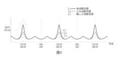
行動載具V1包括一驅動裝置10。在本實施例中,行動載具V1是一機車。驅動裝置10是一一體化啟動發電機(Integrated Starter Generator, ISG)。也就是,驅動裝置10是結合起動機和發電機的兩種操作模式的發電機。在驅動裝置10中有一曲柄軸101。曲柄軸101的轉動可以帶動驅動裝置10在多個角度位置(吸氣、壓縮、排氣、爆發)進行運作。請參閱圖4,其為驅動裝置10在各個角度的啟動阻抗的曲線圖。The mobile vehicle V1 includes a
在本實施例中,驅動裝置10可以不包括減壓機構,驅動裝置10也可以包括一個或是兩個減壓機構。當驅動裝置10包括一個減壓機構時,則是包括一正壓減壓機構。當驅動裝置10包括兩個減壓機構時,則是包括一正壓減壓機構以及一離心式減壓機構。此外,驅動裝置10的曲柄軸101可以正轉以及反轉。其在各角度的啟動阻抗則如圖4所示。In this embodiment, the
行動載具V1的驅動系統SYS包括一控制電路11以及一轉速感測器12。轉速感測器12設置在驅動裝置10上。轉速感測器12連接控制電路11。控制電路11連接驅動裝置10。The driving system SYS of the mobile vehicle V1 includes a
在本實施例中,可以應用於驅動裝置10的驅動控制方法包括下列步驟:In this embodiment, the driving control method applicable to the
步驟S200:轉速感測器偵測所述驅動裝置的一轉速;以及Step S200: The speed sensor detects a speed of the driving device; and
步驟S210:當所述驅動裝置的所述轉速低於一第一預定轉速時,所述控制電路提供多個控制訊號給所述驅動裝置,以使所述驅動裝置停留在一停留角度區間。Step S210: When the rotation speed of the driving device is lower than a first predetermined rotation speed, the control circuit provides a plurality of control signals to the driving device so as to make the driving device stay in a stay angle range.
也就是,在步驟S200中,轉速感測器12會偵測驅動裝置10的曲柄軸101的轉速。而在步驟S210中,當驅動裝置10的曲柄軸101的轉速降低到第一預定轉速以下時(小於等於第一預定轉速),控制電路11就會提供控制訊號給驅動裝置10,將驅動裝置10轉換為馬達模式,進一步控制驅動裝置10的運作。That is, in step S200, the
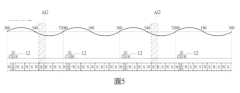
在步驟S210中,控制電路11還會控制驅動裝置10將曲柄軸101停止在一停留角度區間AG裏頭。也就是,當行動載具V1的驅動裝置10降低轉速到0之前,驅動裝置10的曲柄軸101會由控制電路11進行控制,停止在停留角度區間中,以等待再次啟動。而停留在停留角度區間中的驅動裝置10的曲柄軸101,再次啟動時,則可以被預測需要多少啟動阻抗(對應於多少啟動電壓、啟動電流)才可以快速啟動。如此一來,行動載具V1的電池可以有效的被預測其使用壽命以及所需電量。不僅可以有效降低油耗(用於驅動行動載具以及對電池充電),也可以有效的增加電池壽命。In step S210, the
請一併參閱圖4,曲線L1、曲線L2以及曲線L3是不同驅動裝置10的曲柄軸101在各角度的啟動阻抗的曲線圖。Please refer to FIG. 4 , where curves L1 , L2 and L3 are graphs of the starting impedance of the
其中,曲線L1是沒有減壓裝置的阻抗角度曲線。曲線L2是僅有正向減壓裝置的阻抗角度曲線。曲線L3是包括正向減壓裝置以及離心式減壓裝置的阻抗角度曲線。曲線L1對應的啟動阻抗則是高於曲線L2對應的啟動阻抗。曲線L2對應的啟動阻抗則是高於曲線L3對應的啟動阻抗。在本實施例的驅動控制方法,其主要的目的就是讓驅動裝置10的曲柄軸101在停止時,可以跨越啟動阻抗的最高峰值區間,停留在啟動阻抗的最高峰值區間之後的一個角度區間。Among them, curve L1 is an impedance angle curve without a pressure reducing device. Curve L2 is an impedance angle curve with only a forward pressure reducing device. Curve L3 is an impedance angle curve including a forward pressure reducing device and a centrifugal pressure reducing device. The starting impedance corresponding to curve L1 is higher than the starting impedance corresponding to curve L2. The starting impedance corresponding to curve L2 is higher than the starting impedance corresponding to curve L3. The main purpose of the drive control method in this embodiment is to allow the
請參閱圖5,在本實施例中,控制電路11提供多個控制訊號給驅動裝置10,已將驅動裝置10的曲柄軸101停止在例如可以是600度+/-20度的區間之間。驅動裝置10的曲柄軸101在這個角度區間,於再次啟動時,可以處於低耗能狀態。也就是,本案的角度停留的誤差值約是20度左右。然而,驅動裝置10的曲柄軸101停留的角度可以根據驅動裝置10的設計參數進行調整,在本發明中不做限制。Please refer to FIG. 5 . In this embodiment, the
請參閱圖6,控制電路11包括一微控制器111、一開關元件驅動電路112、一開關電路113、一功率控制電路114以及一電池保護電路115。Referring to FIG. 6 , the
微控制器111連接功率控制電路114以及開關元件驅動電路112。The
開關元件驅動電路112電性連接功率控制電路114、電池保護電路115以及開關電路113。The switch
開關電路113則電性連接驅動裝置10,用於控制驅動裝置10。開關電路113可以包括六個主動開關元件或是三個主動開關元件,在本發明中不做限制。The
為了提供較大的功率,驅動裝置10包括的多個線圈(圖未示),可以利用大於對應預定功率的繞製線徑(28AWG)的導線(26AWG)進行繞制,且不限於以上所述。也就是,驅動裝置10的功率設計可以大於預定功率的一倍數,例如1.1倍。提供較大功率的驅動裝置10的導線則需要較粗的線徑,可以承受較大的電流,流經較大的電流則可以提供較強的功率。In order to provide a larger power, the multiple coils (not shown) included in the
在本實施例中,驅動裝置10連接一第一電池單元BA1。也就是,第一電池單元BA1是提供驅動裝置10一電能,以控制驅動裝置10進行轉動。In this embodiment, the driving
請參閱圖7,控制電路11連接一第一電池單元BA1以及一第二電池單元BA2。當驅動裝置10在正常運作的狀況下,第二電池單元BA2不會被使用。也就是,當驅動裝置10在正常運作的狀況下,只有第一電池單元BA1會被使用。Please refer to FIG7 , the
在本實施例中,第一電池單元BA1以及第二電池單元BA2之間包括一連接開關SW1。連接開關SW1連接微控制器111。微控制器111控制連接開關SW1的開啟與關閉,以決定第一電池單元BA1提供電能或是第一電池單元BA1以及第二電池單元BA2共同提供電能。In this embodiment, a connection switch SW1 is included between the first battery cell BA1 and the second battery cell BA2. The connection switch SW1 is connected to the
當驅動裝置10的轉速低於一第一預定轉速時,控制電路11將第一電池單元BA1連接至一第二電池單元BA2,以使第一電池單元BA1與第二電池單元BA2進行並聯,以使第一電池單元BA1與第二電池單元BA2共同提供一電流。此時第一電池單元BA1與第二電池單元BA2共同提供的電流則會大於第一電池單元BA1獨自提供的電流。When the speed of the
當驅動裝置10的轉速高於第一預定轉速時,控制電路11就會將第一電池單元BA1以及第二電池單元BA2斷開,只利用第一電池單元BA1進行供電。When the speed of the driving
在本實施例中,當驅動裝置10的轉速低於第一預定轉速時,驅動裝置10是將要進入一怠速狀態。In this embodiment, when the speed of the driving
請參閱圖8,在本實施例的驅動控制方法還包括下列步驟:Please refer to FIG8 , the driving control method in this embodiment further includes the following steps:
步驟S801:第一電池單元的電量是否小於等於一預定電量?Step S801: Is the power level of the first battery cell less than or equal to a predetermined power level?
步驟S802:驅動裝置的轉速是否大於等於一第二預定轉速?Step S802: Is the rotation speed of the driving device greater than or equal to a second predetermined rotation speed?
步驟S803:對第一電池單元充電。Step S803: charging the first battery unit.
在步驟S801中,控制電路11可以根據第一電池單元BA1的電量決定是否利用驅動裝置10進行充電。也就是,控制電路11可以決定在不同時間區間對第一電池單元BA1進行充電。In step S801, the
在本實施例中,驅動裝置10於再次啟動之後,約30秒至300秒,控制電路11並沒有讓驅動裝置10對第一電池單元BA1進行充電。主要的原因,驅動裝置10的轉速在這個時間區間(30秒至300秒)中,並沒有提高到一個足夠高的轉速,仍在提高速度的過程。此時的驅動裝置10,若是同時驅動行動載具V1以及對第一電池單元BA1進行充電,其油耗會比單獨驅動行動載具V1為高。尤其,當第一電池單元BA1的電量小於等於一預定電量時(例如80%電量),控制電路11則會控制驅動裝置10對第一電池單元BA1進行充電。此外,若是設置第二電池單元BA2,則控制電路11也會偵測第二電池單元BA2的電量,以對第二電池單元BA2進行充電。In this embodiment, after the driving
此外,在步驟S802中,控制電路11根據驅動裝置10的轉速判斷是否對第一電池單元進行充電。也就是,控制電路11可以在驅動裝置10的轉速低於一第二預定轉速之前,不對第一電池單元BA1充電。再者,控制電路11也可以根據第一電池單元BA1的電量,決定不對第一電池單元BA1進行充電的時間長短。也就是,控制電路11可以決定對第一電池單元BA1的不充電時間。當驅動裝置10的轉速高於第二預定轉速之後,控制電路11則會控制驅動裝置10對第一電池單元BA1充電。此處的不充電時間,是從驅動裝置10再次啟動之後開始計算。此外,不充電時間是可以調整的,也就是不充電時間可以大於等於0秒,且小於等於N秒。N在本實施例中是300。In addition, in step S802, the
此外,由於本實施例的控制電路11包括微控制器111。微控制器111是一數位控制器,因此,控制電路11也可以設定多個充電區間,除了根據轉速判斷是否對第一電池單元BA1進行充電,控制電路11還可以根據第一電池單元BA1或是開關電路113的溫度,以判斷是否對第一電池單元BA1進行充電。In addition, since the
[實施例的有益效果][Beneficial Effects of the Embodiments]
本發明的其中一有益效果在於,本發明所提供的驅動控制方法以及驅動系統可以控制行動載具的驅動裝置的再啟動位置,有效降低驅動裝置再次啟動的能耗,更可以根據行動載具的電池單元或是驅動裝置的狀態進行充電方法的調配,有效降低油耗以及提升充電效率。One of the beneficial effects of the present invention is that the drive control method and drive system provided by the present invention can control the restart position of the drive device of the mobile vehicle, effectively reducing the energy consumption of the drive device when restarting again, and can also adjust the charging method according to the status of the battery unit or the drive device of the mobile vehicle, effectively reducing fuel consumption and improving charging efficiency.
以上所公開的內容僅為本發明的優選可行實施例,並非因此侷限本發明的申請專利範圍,所以凡是運用本發明說明書及圖式內容所做的等效技術變化,均包含於本發明的申請專利範圍內。The above disclosed contents are only the preferred feasible embodiments of the present invention, and do not limit the scope of the patent application of the present invention. Therefore, all equivalent technical changes made by using the contents of the description and drawings of the present invention are included in the scope of the patent application of the present invention.
SYS:驅動系統 V1:行動載具 S200-S210, S801-S803:步驟 10:驅動裝置 11:控制電路 101:曲柄軸 L1, L2, L3:曲線 AG:停留角度區間 12:轉速感測器 111:微控制器 112:開關元件驅動電路 113:開關電路 114:功率控制電路 115:電池保護電路 BA1:第一電池單元 BA2:第二電池單元 SW1:連接開關SYS: drive systemV1: mobile vehicleS200-S210, S801-S803: steps10: drive device11: control circuit101: crankshaftL1, L2, L3: curveAG: dwell angle interval12: speed sensor111: microcontroller112: switch element drive circuit113: switch circuit114: power control circuit115: battery protection circuitBA1: first battery unitBA2: second battery unitSW1: connection switch
圖1是本發明第一實施例的驅動控制方法應用於一行動載具的驅動系統的示意圖。FIG1 is a schematic diagram of a driving control method according to a first embodiment of the present invention applied to a driving system of a mobile vehicle.
圖2是本發明第一實施例的驅動控制方法的流程圖。FIG2 is a flow chart of the driving control method of the first embodiment of the present invention.
圖3是行動載具的驅動裝置的示意圖。FIG. 3 is a schematic diagram of a driving device of a mobile vehicle.
圖4是不同驅動裝置的啟動阻抗示意圖。FIG. 4 is a schematic diagram of the starting impedance of different drive devices.
圖5是本發明第一實施例的驅動控制方法的停留角度區間的示意圖。FIG5 is a schematic diagram of the dwell angle interval of the driving control method of the first embodiment of the present invention.
圖6是利用本發明第一實施例的驅動控制方法的驅動系統的示意圖。FIG6 is a schematic diagram of a drive system using the drive control method of the first embodiment of the present invention.
圖7是利用本發明第一實施例的驅動控制方法的驅動系統的另一示意圖。FIG. 7 is another schematic diagram of a drive system using the drive control method of the first embodiment of the present invention.
圖8是本發明第一實施例的驅動控制方法的另一流程圖。FIG8 is another flow chart of the driving control method of the first embodiment of the present invention.
S200-S210:步驟S200-S210: Steps
Claims (10)
Translated fromChinesePriority Applications (1)
| Application Number | Priority Date | Filing Date | Title |
|---|---|---|---|
| TW112135447ATWI873857B (en) | 2023-09-18 | 2023-09-18 | Driving control method and driving system |
Applications Claiming Priority (1)
| Application Number | Priority Date | Filing Date | Title |
|---|---|---|---|
| TW112135447ATWI873857B (en) | 2023-09-18 | 2023-09-18 | Driving control method and driving system |
Publications (2)
| Publication Number | Publication Date |
|---|---|
| TWI873857Btrue TWI873857B (en) | 2025-02-21 |
| TW202513401A TW202513401A (en) | 2025-04-01 |
Family
ID=95557530
Family Applications (1)
| Application Number | Title | Priority Date | Filing Date |
|---|---|---|---|
| TW112135447ATWI873857B (en) | 2023-09-18 | 2023-09-18 | Driving control method and driving system |
Country Status (1)
| Country | Link |
|---|---|
| TW (1) | TWI873857B (en) |
Citations (10)
| Publication number | Priority date | Publication date | Assignee | Title |
|---|---|---|---|---|
| CN1279279C (en)* | 1999-11-24 | 2006-10-11 | 株式会社美姿把 | Starting device for internal combustion engine |
| TW200829461A (en)* | 2006-07-25 | 2008-07-16 | Yamaha Motor Co Ltd | Hybrid motorcycle |
| TW201339413A (en)* | 2012-03-21 | 2013-10-01 | Kwang Yang Motor Co | Control method of reducing engine starting torque |
| TW201542927A (en)* | 2014-05-09 | 2015-11-16 | Sanyang Industry Co Ltd | A method for controlling engine starting of a starter and generator device |
| CN103899465B (en)* | 2012-12-27 | 2016-06-22 | 光阳工业股份有限公司 | Control Method for Reducing Engine Starting Torque |
| CN104242423B (en)* | 2013-06-20 | 2016-08-24 | 光阳工业股份有限公司 | Charging device and charging method for vehicle storage battery |
| CN107035551A (en)* | 2016-02-03 | 2017-08-11 | 光阳工业股份有限公司 | Engine flameout brake control method |
| TWI605191B (en)* | 2014-11-11 | 2017-11-11 | 財團法人工業技術研究院 | Crankshaft angle control method and system thereof |
| CN108661812B (en)* | 2017-03-31 | 2021-01-05 | 光阳工业股份有限公司 | Crankshaft positioning control system and control method for vehicle |
| CN109723593B (en)* | 2017-10-27 | 2021-09-28 | 现代自动车株式会社 | Idle stop and start system and control method thereof |
- 2023
- 2023-09-18TWTW112135447Apatent/TWI873857B/enactive
Patent Citations (10)
| Publication number | Priority date | Publication date | Assignee | Title |
|---|---|---|---|---|
| CN1279279C (en)* | 1999-11-24 | 2006-10-11 | 株式会社美姿把 | Starting device for internal combustion engine |
| TW200829461A (en)* | 2006-07-25 | 2008-07-16 | Yamaha Motor Co Ltd | Hybrid motorcycle |
| TW201339413A (en)* | 2012-03-21 | 2013-10-01 | Kwang Yang Motor Co | Control method of reducing engine starting torque |
| CN103899465B (en)* | 2012-12-27 | 2016-06-22 | 光阳工业股份有限公司 | Control Method for Reducing Engine Starting Torque |
| CN104242423B (en)* | 2013-06-20 | 2016-08-24 | 光阳工业股份有限公司 | Charging device and charging method for vehicle storage battery |
| TW201542927A (en)* | 2014-05-09 | 2015-11-16 | Sanyang Industry Co Ltd | A method for controlling engine starting of a starter and generator device |
| TWI605191B (en)* | 2014-11-11 | 2017-11-11 | 財團法人工業技術研究院 | Crankshaft angle control method and system thereof |
| CN107035551A (en)* | 2016-02-03 | 2017-08-11 | 光阳工业股份有限公司 | Engine flameout brake control method |
| CN108661812B (en)* | 2017-03-31 | 2021-01-05 | 光阳工业股份有限公司 | Crankshaft positioning control system and control method for vehicle |
| CN109723593B (en)* | 2017-10-27 | 2021-09-28 | 现代自动车株式会社 | Idle stop and start system and control method thereof |
Also Published As
| Publication number | Publication date |
|---|---|
| TW202513401A (en) | 2025-04-01 |
Similar Documents
| Publication | Publication Date | Title |
|---|---|---|
| CN102108930B (en) | Engine control apparatus and engine control method | |
| JP5307847B2 (en) | Vehicle power supply system | |
| JP6015171B2 (en) | Power supply device for cars with idle stop | |
| JP2005045883A (en) | Hybrid vehicle | |
| JP2011190735A (en) | Idling stop device, engine start system, and method for starting engine | |
| WO2016181495A1 (en) | Power supply system | |
| CN104579063B (en) | The delay control circuit of generating set and control method | |
| JP7128661B2 (en) | battery diagnostic device | |
| TWI873857B (en) | Driving control method and driving system | |
| JP2016040146A (en) | Control device of hybrid vehicle | |
| TWI852768B (en) | Driving control method and driving system | |
| KR20100024584A (en) | Control apparatus and method for mild hybrid vehicle | |
| JP4618693B2 (en) | Engine power generation system and controller thereof | |
| JP2001268707A (en) | Control device for hybrid vehicle | |
| JP3257204B2 (en) | Control device for vehicle generator | |
| TW201715146A (en) | Method for controlling and protecting power generation after switching off power of a vehicle | |
| JP2004229478A (en) | Power supply control device for vehicles | |
| TWI623455B (en) | ISG system for motorcycle engine and controlling method thereof | |
| JP2004150354A (en) | Operation control device for internal combustion engine | |
| JP6748670B2 (en) | Vehicle power supply | |
| KR100440160B1 (en) | Start up control method of hybrid electric vehicle | |
| JPH0880095A (en) | Internal combustion engine driven power generation system | |
| JP7491475B2 (en) | Hybrid vehicle control device | |
| JP7347997B2 (en) | Vehicle control device | |
| JP5343868B2 (en) | Power generation control device |