TWI872265B - Display system - Google Patents
Display systemDownload PDFInfo
- Publication number
- TWI872265B TWI872265BTW110127059ATW110127059ATWI872265BTW I872265 BTWI872265 BTW I872265BTW 110127059 ATW110127059 ATW 110127059ATW 110127059 ATW110127059 ATW 110127059ATW I872265 BTWI872265 BTW I872265B
- Authority
- TW
- Taiwan
- Prior art keywords
- lens
- image light
- light
- display system
- image
- Prior art date
Links
- 230000000903blocking effectEffects0.000claimsabstractdescription26
- 230000003287optical effectEffects0.000claimsabstractdescription20
- 230000010287polarizationEffects0.000claimsdescription12
- 239000004973liquid crystal related substanceSubstances0.000claimsdescription8
- 230000000007visual effectEffects0.000abstractdescription3
- 238000010586diagramMethods0.000description4
- 238000007654immersionMethods0.000description4
- 239000002184metalSubstances0.000description3
- 230000005540biological transmissionEffects0.000description2
- 230000000694effectsEffects0.000description2
- 230000005684electric fieldEffects0.000description2
- 230000004907fluxEffects0.000description2
- 239000011521glassSubstances0.000description2
- 238000000034methodMethods0.000description2
- 239000002861polymer materialSubstances0.000description2
- 239000011347resinSubstances0.000description2
- 229920005989resinPolymers0.000description2
- 239000000758substrateSubstances0.000description2
- 230000003667anti-reflective effectEffects0.000description1
- 230000003190augmentative effectEffects0.000description1
- 230000001066destructive effectEffects0.000description1
- 238000004519manufacturing processMethods0.000description1
- 239000000463materialSubstances0.000description1
- 238000012986modificationMethods0.000description1
- 230000004048modificationEffects0.000description1
- 238000001579optical reflectometryMethods0.000description1
- 239000002699waste materialSubstances0.000description1
Images


Classifications
- G—PHYSICS
- G02—OPTICS
- G02B—OPTICAL ELEMENTS, SYSTEMS OR APPARATUS
- G02B27/00—Optical systems or apparatus not provided for by any of the groups G02B1/00 - G02B26/00, G02B30/00
- G02B27/01—Head-up displays
- G02B27/017—Head mounted
- G02B27/0172—Head mounted characterised by optical features
- G—PHYSICS
- G02—OPTICS
- G02B—OPTICAL ELEMENTS, SYSTEMS OR APPARATUS
- G02B27/00—Optical systems or apparatus not provided for by any of the groups G02B1/00 - G02B26/00, G02B30/00
- G02B27/28—Optical systems or apparatus not provided for by any of the groups G02B1/00 - G02B26/00, G02B30/00 for polarising
- G02B27/286—Optical systems or apparatus not provided for by any of the groups G02B1/00 - G02B26/00, G02B30/00 for polarising for controlling or changing the state of polarisation, e.g. transforming one polarisation state into another
- G—PHYSICS
- G02—OPTICS
- G02F—OPTICAL DEVICES OR ARRANGEMENTS FOR THE CONTROL OF LIGHT BY MODIFICATION OF THE OPTICAL PROPERTIES OF THE MEDIA OF THE ELEMENTS INVOLVED THEREIN; NON-LINEAR OPTICS; FREQUENCY-CHANGING OF LIGHT; OPTICAL LOGIC ELEMENTS; OPTICAL ANALOGUE/DIGITAL CONVERTERS
- G02F1/00—Devices or arrangements for the control of the intensity, colour, phase, polarisation or direction of light arriving from an independent light source, e.g. switching, gating or modulating; Non-linear optics
- G02F1/01—Devices or arrangements for the control of the intensity, colour, phase, polarisation or direction of light arriving from an independent light source, e.g. switching, gating or modulating; Non-linear optics for the control of the intensity, phase, polarisation or colour
- G02F1/13—Devices or arrangements for the control of the intensity, colour, phase, polarisation or direction of light arriving from an independent light source, e.g. switching, gating or modulating; Non-linear optics for the control of the intensity, phase, polarisation or colour based on liquid crystals, e.g. single liquid crystal display cells
Landscapes
- Physics & Mathematics (AREA)
- General Physics & Mathematics (AREA)
- Optics & Photonics (AREA)
- Nonlinear Science (AREA)
- Chemical & Material Sciences (AREA)
- Crystallography & Structural Chemistry (AREA)
- Electroluminescent Light Sources (AREA)
- Devices For Indicating Variable Information By Combining Individual Elements (AREA)
Abstract
Description
Translated fromChinese本發明涉及顯示技術領域,尤其涉及一種顯示系統。The present invention relates to the field of display technology, and in particular to a display system.
虛擬實境(virtual reality)技術已經在軍事、建築、旅遊、電影、多媒體及電競等領域急速地發展。應用虛擬實境科技的裝置可以被分類為虛擬實境(Virtual Reality,VR)裝置或是擴增實境(Augmented Reality,AR)裝置。這些裝置包含了正在發展中的顯示裝置,例如,頭戴式顯示裝置HMD(Head Mounted Display,HMD)。在頭戴式顯示裝置中,影像光束由顯示裝置發出後經鏡頭傳遞至使用者的眼睛。然而,部分影像光束在傳遞過程中易於鏡頭與顯示裝置之間產生反射,而讓使用者觀看到不必要的影像信息,即鬼影(Ghost Image)。另一方面,組成鏡頭的透鏡的平面結構通常為圓形,透鏡具有靠近圓心的內圈和圍繞該內圈的外圈。由於在製作透鏡時,透鏡的外圈相較於內圈比較難進行加工,透鏡的外圈易存在機構誤差。所以當光束從透鏡外圈透射時易產生相較於光束從透鏡內圈的部分透射時候的頻率較高的光,進一步加大了鬼影效應並且會導致透射到人眼的部分的影像的對比度較大,從而導致用戶在虛擬現實中的沉浸感降低。Virtual reality technology has developed rapidly in the fields of military, architecture, tourism, film, multimedia and e-sports. Devices that apply virtual reality technology can be classified as virtual reality (VR) devices or augmented reality (AR) devices. These devices include display devices that are under development, such as head-mounted display (HMD). In a head-mounted display, the image beam is emitted by the display device and transmitted to the user's eyes through the lens. However, part of the image beam is easily reflected between the lens and the display device during the transmission process, allowing the user to see unnecessary image information, namely ghost images. On the other hand, the plane structure of the lens constituting the lens is usually circular, and the lens has an inner ring near the center of the circle and an outer ring surrounding the inner ring. Since the outer ring of the lens is more difficult to process than the inner ring when manufacturing the lens, the outer ring of the lens is prone to mechanical errors. Therefore, when the light beam is transmitted from the outer ring of the lens, it is easy to generate light with a higher frequency than when the light beam is partially transmitted from the inner ring of the lens, further increasing the ghost effect and causing the contrast of the image transmitted to the human eye to be greater, thereby reducing the user's sense of immersion in virtual reality.
本申請提供一種顯示系統,包括:顯示裝置,具有顯示面,該顯示面用於發出圖像光;及第一透鏡組件,包括:第一透鏡,設置於該圖像光的光路上,用於聚焦該圖像光;及光阻擋層,設置於該第一透鏡的一側,該光阻擋層用於吸收部分該圖像光及吸收外部光束,另一部分該圖像光從該第一透鏡遠離該顯示裝置的一側透射以顯示VR圖像或AR圖像。The present application provides a display system, comprising: a display device having a display surface, the display surface being used to emit image light; and a first lens assembly, comprising: a first lens, arranged on the optical path of the image light, and used to focus the image light; and a light blocking layer, arranged on one side of the first lens, the light blocking layer being used to absorb part of the image light and absorb external light beams, and another part of the image light is transmitted from the first lens away from the side of the display device to display VR images or AR images.
本申請實施例的顯示系統,包括顯示裝置、第一透鏡和光阻擋層,顯示裝置用於出射圖像光,第一透鏡用於接收該圖像光,第一透鏡接收的部分圖像光易形成高頻的雜散光而導致產生鬼影現象,光阻擋層用於吸收掉該雜散光,因此藉由設置光阻擋層,能夠有效減少該顯示系統中產生的雜散光,進而改善鬼影現象。The display system of the embodiment of the present application includes a display device, a first lens and a light blocking layer. The display device is used to emit image light, and the first lens is used to receive the image light. Part of the image light received by the first lens is prone to form high-frequency stray light, resulting in a ghost phenomenon. The light blocking layer is used to absorb the stray light. Therefore, by setting the light blocking layer, the stray light generated in the display system can be effectively reduced, thereby improving the ghost phenomenon.
100、200:顯示系統100, 200: Display system
10:顯示裝置10: Display device
20:第一透鏡組件20: First lens assembly
30:第二透鏡組件30: Second lens assembly
21:第一透鏡21: First lens
31:第二透鏡31: Second lens
32:調焦部32: Focusing Department
211:第一表面211: First surface
212:第二表面212: Second surface
213:第一抗反射層213: First anti-reflection layer
214:半反射膜214: Semi-reflective film
215、315:光阻擋層215, 315: Light blocking layer
216:第一區域216: First Area
217:第二區域217: Second Area
22:反射式偏振片22: Reflective polarizer
13、23:四分之一波片13, 23: Quarter wave plate
33a:第一線偏振片33a: First linear polarizer
33b:第二線偏振片33b: Second linear polarizer
34:第二抗反射層34: Second anti-reflective layer
11:顯示面11: Display surface
12:第三線偏振片12: Third linear polarizer
131、231:光軸131, 231: Light axis
L1:圖像光L1: Image light
圖1為本申請第一實施例的顯示系統的結構示意圖。Figure 1 is a schematic diagram of the structure of the display system of the first embodiment of this application.
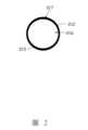
圖2是圖1中第一透鏡的第二表面的平面結構示意圖。Figure 2 is a schematic diagram of the planar structure of the second surface of the first lens in Figure 1.
圖3是本申請第二實施例的顯示系統的結構示意圖。Figure 3 is a schematic diagram of the structure of the display system of the second embodiment of this application.
圖4是本申請第三實施例的顯示系統的結構示意圖。Figure 4 is a schematic diagram of the structure of the display system of the third embodiment of this application.
下面將結合本發明實施例中的附圖,對本發明實施例中的技術方案進行清楚、完整地描述,顯然,所描述的實施例是本發明一部分實施例,而不是全部的實施例。The following will combine the attached figures in the embodiments of the present invention to clearly and completely describe the technical solutions in the embodiments of the present invention. Obviously, the described embodiments are part of the embodiments of the present invention, not all of them.
除非另有定義,本文所使用的所有的技術和科學術語與屬於本發明的技術領域的技術人員通常理解的含義相同。本文中在本發明的說明書中所使用的術語只是為了描述具體的實施例的目的,不是只限制於本發明。Unless otherwise defined, all technical and scientific terms used herein have the same meaning as those commonly understood by technicians in the technical field of the present invention. The terms used in this specification of the present invention are only for the purpose of describing specific embodiments and are not limited to the present invention.
為能進一步闡述本發明達成預定目的所採取的技術手段及功效,以下結合附圖及較佳實施方式,對本發明作出如下詳細說明。In order to further explain the technical means and effects adopted by the present invention to achieve the intended purpose, the present invention is described in detail below in conjunction with the attached drawings and the preferred implementation method.
本申請實施例提供的顯示系統,包括:顯示裝置,具有顯示面,該顯示面用於發出圖像光;及第一透鏡組件,包括:第一透鏡,設置於該圖像光的光路上,用於聚焦該圖像光;及光阻擋層,設置於該第一透鏡的一側,該光阻擋層用於吸收部分該圖像光及吸收外部光束。以下實施例對該顯示系統進行詳細說明。The display system provided by the embodiment of the present application includes: a display device having a display surface, the display surface is used to emit image light; and a first lens assembly, including: a first lens, arranged on the optical path of the image light, and used to focus the image light; and a light blocking layer, arranged on one side of the first lens, the light blocking layer is used to absorb part of the image light and absorb external light beams. The following embodiment describes the display system in detail.
實施例一Implementation Example 1
請參閱圖1,本申請第一實施例中顯示系統100包括:顯示裝置10、第一透鏡組件20和第二透鏡組件30。顯示裝置10具有顯示面11,顯示面11用於發出圖像光L1。在本實施例中,顯示裝置10可為液晶顯示裝置(Liquid Crystal Display,LCD)、有機發光二極管顯示裝置(Organic Light Emitting Diode,OLED)或其他種類的顯示裝置,但不以此為限。在本實施例中,圖像光L1攜帶影像信息,而圖像光L1也可稱為影像光束。Please refer to FIG. 1 . In the first embodiment of the present application, the
第一透鏡組件20設置於圖像光L1的光路上且與顯示裝置10間隔,包括第一透鏡21。第一透鏡21設置於圖像光L1的光路上。第一透鏡21具有面向顯示裝置10的第一表面211和背向顯示裝置10的第二表面212。請參閱圖2,第二表面212包括相互拼接的第一區域216和第二區域217,第二區域217圍繞第一區域216,即第二區域217相對於第一區域216更靠近第一透鏡21的外緣。第一透鏡21用於聚焦圖像光L1。在本實施例中,第一透鏡21可以是單個或複數透鏡的組合。The
當透鏡應用於VR或者AR的光路系統時,從透鏡內圈的部分透射的光為比較穩定的低頻光,但是光束從透鏡外圈的部分透射時易產生高頻光,該高頻光會導致透射到人眼的部分影像的對比度降低,從而導致用戶在虛擬現實中的沉浸感降低。本實施例中,圖像光L1從第一透鏡21的第二區域217透射的部分通常包含有雜散光。該雜散光會導致圖像光L1中進入人眼後,使人眼感受到部分影像的對比度降低,從而導致用戶在虛擬現實中的沉浸感降低。並且,圖像光以外的,從外部環境進入顯示系統100的外部光束從第一透鏡21的第二區域217透射時,也會產生高頻光,導致透射到人眼的部分的影像的對比度降低,從而導致用戶在虛擬現實中的沉浸感降低。為解決上述問題,請參閱圖1和圖2,在本實施例中,第一透鏡組件20還包括光阻擋層215,光阻擋層215位於第二表面212的第二區域217。光阻擋層215用於吸收從第二區域217經過的部分圖像光L1以及吸收從第二區域217經過的外部光束,以避免該部分圖像光L1及外部光束從第二區域217透射,在本實施例中,光阻擋層215可以為黑化層、金屬層或者樹脂等高分子材料,但不以此為限,只要能阻擋光線透過即可。When the lens is used in the optical path system of VR or AR, the light transmitted from the inner part of the lens is relatively stable low-frequency light, but the light beam is easily transmitted from the outer part of the lens, which is prone to generate high-frequency light. The high-frequency light will cause the contrast of the part of the image transmitted to the human eye to decrease, thereby reducing the user's immersion in the virtual reality. In this embodiment, the part of the image light L1 transmitted from the
由於在顯示裝置10和第一透鏡21之間具有空氣間隙,該空氣間隙的光反射率約為4%,圖像光L1透過上述空氣間隙時會發生反射,所以會導致顯示系統100中光通量的下降,最終導致成像的亮度不足。在本實施例中,第一透鏡組件20還包括第一抗反射層213,第一抗反射層213位於第一透鏡21的第一表面211,第一抗反射層213位於第一表面211能有效減少第一透鏡21對於從顯示裝置10發出的圖像光L1的反射,以增大系統中的光通量。第一抗反射層213可以是能使得圖像光L1發生干涉的干涉膜,也可以是其它種類的抗反射層。Since there is an air gap between the
第一透鏡組件20還包括半反射膜214,半反射膜214位於第一透鏡21的第二表面212,當圖像光L1入射到半反射膜214時,部分圖像光L1會被半反射膜214反射,未被反射的圖像光L1則會從半反射膜214透射。半反射膜214可以為金屬等具有反射並可以被光束透射的材料製成,但不以此為限。The
第一透鏡組件20還包括反射式偏振片22和四分之一波片23。反射式偏振片22設置於第一透鏡21和第二透鏡組件30之間,反射式偏振片22,反射式偏振片22具有一個偏振方向,反射式偏振片22可以透射與反射式偏振片22偏振方向相同的圖像光L1並反射與反射式偏振片22偏振方向不同的圖像光L1。四分之一波片23設置於第一透鏡21和反射式偏振片22之間,四分之一波片23用於將入射到四分之一波片23的圖像光L1從圓偏振光轉化為線偏振光或者將圖像光L1從線偏振光轉化為圓偏振光。為滿足線偏振光轉化為圓偏振光的條件,需要設置四分之一波片23的光軸231與反射式偏振片22的偏振方向的夾角為45°。The
第二透鏡組件30設置於從第一透鏡組件20出射的圖像光L1的光路上,用於傳輸對從第一透鏡組件20出射的圖像光L1進行濾光處理和調整從第一透鏡組件20出射的圖像光L1的焦距以顯示該VR圖像或該AR圖像。第二透鏡組件30包括第二透鏡31和調焦部32。第二透鏡31設置於第一透鏡組件的出射的圖像光L1的光路上,用於透射並聚焦從第一透鏡組件20出射的圖像光L1。在本實施例中,第二透鏡31可以是單個或複數透鏡的組合,第二透鏡31也可進一步包括為透鏡以外的其它光學構件,但不以此為限。The
調焦部32設置於從第二透鏡31透射的圖像光L1的光路上。調焦部32用於調整顯示系統100的焦距,調焦部32可以為液晶透鏡等其他可以調節光路焦距的元件,在本實施例中以調焦部32為液晶透鏡進行說明,但不以此為限。本實施例中,調焦部32由兩塊玻璃基板和液晶分子組成,當在玻璃基板上施加電場時,液晶分子會改變方向,導致從透鏡透射的光線會重新聚焦,藉由調節電場和液晶分子的方向,可以調塑光束,從而調節液晶的折射率,以實現變焦。調焦部32可以使顯示系統100在不需要配備機械部件的情況下實現自動對焦和變焦,並且控制電壓低,避免了電能浪費。本實施例中,調焦部32以電驅動的方式來調整顯示系統100的焦距,調焦部32可以單個元件結構進行調焦或者以複數元件結構組合進行調焦,但不以此為限。The focusing
藉由設置調焦部32,使得使用者可以根據實際情況調節顯示系統100的焦距,以滿足使用者對於不同焦距的圖像的需求。By providing the
第二透鏡組件30還包括第一線偏振片33a和第二線偏振片33b。第一線偏振片33a設置於第二透鏡31和調焦部32之間,並設置於從調焦部32透射的圖像光L1的光路上。第一線偏振片33a具有一個偏振方向,可以透射與第一線偏振片33a偏振方向相同的圖像光L1,並且吸收與第一線偏振片33a偏振方向不同的圖像光L1,藉由第一線偏振片33a的設置,可以阻擋顯示系統100中由於反射式偏振片22和透鏡間的來回反射產生的雜散光,以顯著地改善鬼影現象,提升視覺效果。第二線偏振片33b設置於調焦部32的出光光路上,用於阻擋圖像光L1在經過調焦部32調整焦距後產生的雜散光,以起到提升圖像的視覺效果。The
第一線偏振片33a的偏振方向、第二線偏振片33b的偏振方向以及反射式偏振片22的偏振方向被配置為相同的;且反射式偏振片22的光路透射方向、第一線偏振片33a的光路透射方向以及第二線偏振片33b光路透射方向也被配置成相同的,即朝向顯示裝置10傳輸的光束從反射式偏振片22、第一線偏振片33a以及第二線偏振片33b透射時,該光束會被反射式偏振片22反射或被第一線偏振片33a吸收或被第二線偏振片33b吸收,無法從上述元件透射。The polarization directions of the first
顯示裝置10包括第三線偏振片12和四分之一波片13。四分之一波片13設置於顯示面11發出的圖像光L1的光路上,第三線偏振片12設置於四分之一波片13和顯示面11之間。第三線偏振片12具有偏振方向,用於透射與第三線偏振片12偏振方向相同的圖像光L1,四分之一波片13用於將從第三線偏振片12透射後的圖像光L1轉化為圓偏振光。第三線偏振片12和四分之一波片13組合用於將顯示裝置10的顯示面11發出的圖像光L1轉化為圓偏振光。為滿足線偏振光轉化為圓偏振光的條件,需要設置四分之一波片13的光軸131與第三線偏振片12的偏振方向的夾角為45°。The
實施例二Implementation Example 2
請參閱圖3,本申請的第二實施例的顯示系統200與顯示系統100基本相似,不同之處主要在於光阻擋層315不再位於第一透鏡21的第二表面212,而設置在第一透鏡21和四分之一波片23之間。光阻擋層315遮住第一透鏡21的第二區域217。光阻擋層315用於吸收從第二區域217經過的部分圖像光L1,另一部分圖像光L1從第一區域216透射遠離顯示裝置10的一側射以顯示VR圖像或AR圖像。在本實施例中,光阻擋層315為一圓環結構,但不以此為限;光阻擋層315不設置在透鏡的表面上可以防止光阻擋層315與透鏡接觸而導致磨損,以起到增延長第一透鏡21使用壽命的作用。在本實施例中,光阻擋層315可以為黑化層、金屬層或者樹脂等高分子材料,但不以此為限。此外,顯示系統200其它部分的結構以及光路走向與實施例一中的顯示系統100的對應部分的結構和光路走向相同,在此不再進行贅述。Please refer to FIG. 3 . The
實施例三Implementation Example 3
請參閱圖4,本申請的第三實施例的顯示系統300與顯示系統100基本相似,不同之處在於在從第二線偏振片33b透射的圖像光L1的光路上設置有第二抗反射層34。由於顯示系統300在使用過程中會受到周圍環境的影響,會有環境光等雜散光進入到顯示系統300中。所以當雜散光進入顯示系統300後,會在顯示系統300發生反射,讓使用者看到不必要的影像信息,即產生鬼影。所以,本實施例中,第二抗反射層34可以抑制顯示系統300中該環境光的反射以及抑制從第二線偏振片33b透射的圖像光L1的反射。第二抗反射層34可以是能夠針對圖像光L1的波長產生破壞性干涉的干涉膜,但不以此為限,在其它實施例中,第二抗反射層34也可以是其它種類的抗反射層。此外,顯示系統300其它部分的結構以及光路走向與實施例一中的顯示系統100的對應部分的結構和光路走向相同,在此不再進行贅述。Please refer to FIG. 4 . The
本技術領域的普通技術人員應當認識到,以上的實施方式僅是用來說明本申請,而並非用作為對申請的限定,只要在本申請的實質精神範圍之內,對以上實施例所作的適當改變和變化都落在本申請要求保護的範圍之內。Ordinary technicians in this technical field should recognize that the above implementation is only used to illustrate this application, and is not used as a limitation on the application. As long as it is within the spirit of the application, appropriate changes and modifications to the above implementation are within the scope of protection required by this application.
100:顯示系統100: Display system
10:顯示裝置10: Display device
20:第一透鏡組件20: First lens assembly
30:第二透鏡組件30: Second lens assembly
21:第一透鏡21: First lens
31:第二透鏡31: Second lens
32:調焦部32: Focusing Department
211:第一表面211: First surface
212:第二表面212: Second surface
213:第一抗反射層213: First anti-reflection layer
214:半反射膜214: Semi-reflective film
215:光阻擋層215: Light blocking layer
216:第一區域216: First Area
217:第二區域217: Second Area
22:反射式偏振片22: Reflective polarizer
13、23:四分之一波片13, 23: Quarter wave plate
33a:第一線偏振片33a: First linear polarizer
33b:第二線偏振片33b: Second linear polarizer
11:顯示面11: Display surface
12:第三線偏振片12: Third linear polarizer
131、231:光軸131, 231: Light axis
L1:圖像光L1: Image light
Claims (7)
Translated fromChineseApplications Claiming Priority (2)
| Application Number | Priority Date | Filing Date | Title |
|---|---|---|---|
| CN202110764314.9 | 2021-07-06 | ||
| CN202110764314.9ACN113376841A (en) | 2021-07-06 | 2021-07-06 | Display system |
Publications (2)
| Publication Number | Publication Date |
|---|---|
| TW202303223A TW202303223A (en) | 2023-01-16 |
| TWI872265Btrue TWI872265B (en) | 2025-02-11 |
Family
ID=77581169
Family Applications (1)
| Application Number | Title | Priority Date | Filing Date |
|---|---|---|---|
| TW110127059ATWI872265B (en) | 2021-07-06 | 2021-07-22 | Display system |
Country Status (2)
| Country | Link |
|---|---|
| CN (1) | CN113376841A (en) |
| TW (1) | TWI872265B (en) |
Families Citing this family (4)
| Publication number | Priority date | Publication date | Assignee | Title |
|---|---|---|---|---|
| CN113960798A (en)* | 2021-11-03 | 2022-01-21 | 上海鱼微阿科技有限公司 | Large-caliber optical assembly |
| CN114706226B (en)* | 2022-04-29 | 2023-12-12 | 业成科技(成都)有限公司 | Virtual reality display system and head-mounted display device |
| CN114935822A (en)* | 2022-06-15 | 2022-08-23 | 业成科技(成都)有限公司 | Optical system |
| CN116909026A (en)* | 2023-08-02 | 2023-10-20 | 业成科技(成都)有限公司 | Head-mounted display device |
Citations (9)
| Publication number | Priority date | Publication date | Assignee | Title |
|---|---|---|---|---|
| CN106501935A (en)* | 2015-09-03 | 2017-03-15 | 3M创新有限公司 | Head mounted display |
| CN106575037A (en)* | 2014-08-13 | 2017-04-19 | 3M创新有限公司 | Head-mounted display system and components |
| TW201732371A (en)* | 2016-01-22 | 2017-09-16 | 康寧公司 | Wide field personal display |
| JP6249366B2 (en)* | 2014-06-10 | 2017-12-20 | 国立大学法人東北大学 | Image display device |
| US20180003919A1 (en)* | 2016-06-29 | 2018-01-04 | Lg Electronics Inc. | Head mounted display and method for controlling the same |
| US20180136468A1 (en)* | 2016-11-16 | 2018-05-17 | Google Llc | Freeform projected display |
| CN108713159A (en)* | 2016-03-02 | 2018-10-26 | 欧库勒斯虚拟现实有限责任公司 | Field Curvature Corrected Display |
| CN110187506A (en)* | 2019-05-28 | 2019-08-30 | 京东方科技集团股份有限公司 | Optical display systems and augmented reality devices |
| CN110325895A (en)* | 2017-02-21 | 2019-10-11 | 脸谱科技有限责任公司 | Focus adjustment multi-plane head-mounted display |
Family Cites Families (6)
| Publication number | Priority date | Publication date | Assignee | Title |
|---|---|---|---|---|
| DE602005020425D1 (en)* | 2004-02-09 | 2010-05-20 | Tamron Kk | OPTICAL SYSTEM FOR IMAGING WITH CHROMATIC ABERRATION CORRECTION |
| JP2009086644A (en)* | 2007-09-12 | 2009-04-23 | Fujinon Corp | Imaging lens and imaging apparatus |
| JP6786248B2 (en)* | 2016-04-12 | 2020-11-18 | キヤノン株式会社 | Optical element and its manufacturing method |
| WO2018168326A1 (en)* | 2017-03-16 | 2018-09-20 | ソニー株式会社 | Optical component, method for manufacturing optical component, and image display device |
| TWI690745B (en)* | 2019-06-26 | 2020-04-11 | 點晶科技股份有限公司 | Multifunctional eyeglasses |
| CN112666708B (en)* | 2020-12-24 | 2023-06-27 | 业成科技(成都)有限公司 | Composite optical device and method for manufacturing the same |
- 2021
- 2021-07-06CNCN202110764314.9Apatent/CN113376841A/enactivePending
- 2021-07-22TWTW110127059Apatent/TWI872265B/enactive
Patent Citations (9)
| Publication number | Priority date | Publication date | Assignee | Title |
|---|---|---|---|---|
| JP6249366B2 (en)* | 2014-06-10 | 2017-12-20 | 国立大学法人東北大学 | Image display device |
| CN106575037A (en)* | 2014-08-13 | 2017-04-19 | 3M创新有限公司 | Head-mounted display system and components |
| CN106501935A (en)* | 2015-09-03 | 2017-03-15 | 3M创新有限公司 | Head mounted display |
| TW201732371A (en)* | 2016-01-22 | 2017-09-16 | 康寧公司 | Wide field personal display |
| CN108713159A (en)* | 2016-03-02 | 2018-10-26 | 欧库勒斯虚拟现实有限责任公司 | Field Curvature Corrected Display |
| US20180003919A1 (en)* | 2016-06-29 | 2018-01-04 | Lg Electronics Inc. | Head mounted display and method for controlling the same |
| US20180136468A1 (en)* | 2016-11-16 | 2018-05-17 | Google Llc | Freeform projected display |
| CN110325895A (en)* | 2017-02-21 | 2019-10-11 | 脸谱科技有限责任公司 | Focus adjustment multi-plane head-mounted display |
| CN110187506A (en)* | 2019-05-28 | 2019-08-30 | 京东方科技集团股份有限公司 | Optical display systems and augmented reality devices |
Also Published As
| Publication number | Publication date |
|---|---|
| TW202303223A (en) | 2023-01-16 |
| CN113376841A (en) | 2021-09-10 |
Similar Documents
| Publication | Publication Date | Title |
|---|---|---|
| TWI872265B (en) | Display system | |
| KR102578625B1 (en) | Substrate-guided optical device | |
| US9946074B2 (en) | See-through curved eyepiece with patterned optical combiner | |
| JP7151255B2 (en) | virtual image display | |
| WO2017038350A1 (en) | Optical device and method for producing same, and display device | |
| EP4303641A1 (en) | Near-to-eye display optical system, optical filter and near-to-eye display device | |
| CN1867855A (en) | Substrate-guided optical devices | |
| US20200041795A1 (en) | Virtual image display device and enlargement optical system | |
| US20180373038A1 (en) | Optics of wearable display devices | |
| US11860506B2 (en) | Virtual reality display system and head-mounted display apparatus | |
| CN114488538B (en) | AR ray apparatus and wear display device | |
| CN114859560A (en) | Optical modules and head-mounted display devices | |
| CN112162382B (en) | Lenses, projection optics and near-eye display systems | |
| US20250004277A1 (en) | Virtual image display device and optical unit | |
| CN114144716B (en) | Optical system for displaying magnified virtual image | |
| CN219799825U (en) | Light guide system, light source device and display equipment | |
| WO2022178406A1 (en) | Display device including polarization selective microlens array | |
| US20240418996A1 (en) | Display device | |
| US20250004276A1 (en) | Virtual image display device and optical unit | |
| US20250138321A1 (en) | Virtual-image display device and optical unit | |
| US20250291190A1 (en) | Virtual image display device and optical unit | |
| US20250004278A1 (en) | Virtual image display device and optical unit | |
| HK1097917B (en) | Substrate-guided optical devices |