TWI871041B - Glasses type display device - Google Patents
Glasses type display deviceDownload PDFInfo
- Publication number
- TWI871041B TWI871041BTW112138645ATW112138645ATWI871041BTW I871041 BTWI871041 BTW I871041BTW 112138645 ATW112138645 ATW 112138645ATW 112138645 ATW112138645 ATW 112138645ATW I871041 BTWI871041 BTW I871041B
- Authority
- TW
- Taiwan
- Prior art keywords
- pivot
- assembly
- upper pivot
- display device
- connecting portion
- Prior art date
Links
- 239000011521glassSubstances0.000title1
- 239000004020conductorSubstances0.000claims1
- 230000003287optical effectEffects0.000description4
- 230000009286beneficial effectEffects0.000description2
- 230000003190augmentative effectEffects0.000description1
- 238000005452bendingMethods0.000description1
- 238000010586diagramMethods0.000description1
- 230000000694effectsEffects0.000description1
- 238000000034methodMethods0.000description1
- 230000001681protective effectEffects0.000description1
- 230000008054signal transmissionEffects0.000description1
Images


Classifications
- G—PHYSICS
- G02—OPTICS
- G02B—OPTICAL ELEMENTS, SYSTEMS OR APPARATUS
- G02B27/00—Optical systems or apparatus not provided for by any of the groups G02B1/00 - G02B26/00, G02B30/00
- G02B27/01—Head-up displays
- G02B27/017—Head mounted
- G02B27/0176—Head mounted characterised by mechanical features
- G—PHYSICS
- G02—OPTICS
- G02C—SPECTACLES; SUNGLASSES OR GOGGLES INSOFAR AS THEY HAVE THE SAME FEATURES AS SPECTACLES; CONTACT LENSES
- G02C5/00—Constructions of non-optical parts
- G02C5/22—Hinges
- G02C5/2209—Pivot bearings and hinge bolts other than screws
- G—PHYSICS
- G02—OPTICS
- G02C—SPECTACLES; SUNGLASSES OR GOGGLES INSOFAR AS THEY HAVE THE SAME FEATURES AS SPECTACLES; CONTACT LENSES
- G02C11/00—Non-optical adjuncts; Attachment thereof
- G02C11/10—Electronic devices other than hearing aids
- G—PHYSICS
- G02—OPTICS
- G02C—SPECTACLES; SUNGLASSES OR GOGGLES INSOFAR AS THEY HAVE THE SAME FEATURES AS SPECTACLES; CONTACT LENSES
- G02C5/00—Constructions of non-optical parts
- G02C5/14—Side-members
- G—PHYSICS
- G02—OPTICS
- G02C—SPECTACLES; SUNGLASSES OR GOGGLES INSOFAR AS THEY HAVE THE SAME FEATURES AS SPECTACLES; CONTACT LENSES
- G02C5/00—Constructions of non-optical parts
- G02C5/22—Hinges
- G—PHYSICS
- G02—OPTICS
- G02B—OPTICAL ELEMENTS, SYSTEMS OR APPARATUS
- G02B27/00—Optical systems or apparatus not provided for by any of the groups G02B1/00 - G02B26/00, G02B30/00
- G02B27/01—Head-up displays
- G02B27/017—Head mounted
- G02B2027/0178—Eyeglass type
Landscapes
- Physics & Mathematics (AREA)
- Health & Medical Sciences (AREA)
- General Physics & Mathematics (AREA)
- Optics & Photonics (AREA)
- Ophthalmology & Optometry (AREA)
- Acoustics & Sound (AREA)
- General Health & Medical Sciences (AREA)
- Otolaryngology (AREA)
- Eyeglasses (AREA)
- Devices For Indicating Variable Information By Combining Individual Elements (AREA)
Abstract
Description
Translated fromChinese本發明是有關於一種顯示裝置,且特別是有關於一種眼鏡型顯示裝置。The present invention relates to a display device, and in particular to a glasses-type display device.
目前用於虛擬實境的顯示裝置較為常見的類型是頭戴式顯示裝置。頭戴式顯示裝置的一種常見類型是眼鏡型顯示裝置,其可折疊的鏡腳可大幅減少儲存空間,這有利於可攜帶性。Currently, the most common type of display device used for virtual reality is a head-mounted display device. One common type of head-mounted display device is a glasses-type display device, whose foldable temples can significantly reduce storage space, which is conducive to portability.
本發明提供一種眼鏡型顯示裝置,具有可收折的鏡腳以減少儲存空間。The present invention provides a glasses-type display device having foldable temples to reduce storage space.
本發明的眼鏡型顯示裝置包括一前端組件、一第一鏡腳、一第二鏡腳、一樞接組件及一導線。第一鏡腳樞接至前端組件。樞接組件設於前端組件與第二鏡腳之間,以將第二鏡腳樞接至前端組件。樞接組件包括一第一連接部及一第二連接部。第一連接部連接至前端組件與第二鏡腳其中的一個,並具有一第一上樞接部及一第一下樞接部。第二連接部連接至前端組件與第二鏡腳其中的另一個,並具有一第二上樞接部及一第二下樞接部。第一上樞接部與第二上樞接部在一樞轉軸線上彼此配合,且第一下樞接部與第二下樞接部在樞轉軸線上彼此配合,使得第二連接部相對於第一連接部在樞轉軸線上樞轉。導線從前端組件延伸穿過第一上樞接部或第二上樞接部與第一下樞接部或第二下樞接部之間的空間而到達第二鏡腳。The eyeglass-type display device of the present invention includes a front-end assembly, a first mirror leg, a second mirror leg, a pivot assembly and a wire. The first mirror leg is pivoted to the front-end assembly. The pivot assembly is arranged between the front-end assembly and the second mirror leg to pivot the second mirror leg to the front-end assembly. The pivot assembly includes a first connecting portion and a second connecting portion. The first connecting portion is connected to one of the front-end assembly and the second mirror leg, and has a first upper pivot portion and a first lower pivot portion. The second connecting portion is connected to the other of the front-end assembly and the second mirror leg, and has a second upper pivot portion and a second lower pivot portion. The first upper pivot and the second upper pivot cooperate with each other on a pivot axis, and the first lower pivot and the second lower pivot cooperate with each other on the pivot axis, so that the second connection portion pivots on the pivot axis relative to the first connection portion. The wire extends from the front end assembly through the space between the first upper pivot or the second upper pivot and the first lower pivot or the second lower pivot to reach the second temple.
基於上述,在本發明中,將用於樞轉的軸體分成有間隔的兩部分以讓導線延伸經過,這有利於減少外觀尺寸,並可讓導線可自然彎曲以延長使用壽命。Based on the above, in the present invention, the shaft for pivoting is divided into two spaced parts to allow the wire to extend through, which is beneficial to reducing the external dimensions and allows the wire to bend naturally to extend the service life.
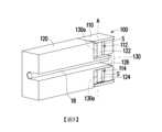
請參考圖1,在本發明的一實施例中,眼鏡型顯示裝置10包括一前端組件12。前端組件12可包括光學系統(未繪示)以及保護外殼等構件,並可設置顯示器或適於放置顯示器。前述顯示器可以是內建顯示器或外加的可攜式顯示器(例如智慧型手機等),但不限於此。前述顯示器的種類可依據眼鏡型顯示裝置10應用在虛擬實境系統(virtual reality system)、擴增實境系統(augmented reality system)或混合實境系統(mixed reality system)中而有所調整。光學系統包括用於改變顯示器的光路的光學元件,例如為透鏡、導光件或稜鏡等。Please refer to FIG. 1 . In one embodiment of the present invention, the eyeglass-
請再參考圖1,眼鏡型顯示裝置10更包括一第一鏡腳14、一第二鏡腳16及一樞接組件100。第一鏡腳14樞接至前端組件12。樞接組件100設於前端組件12與第二鏡腳16之間,以將第二鏡腳16樞接至前端組件12。在本實施例中,第一鏡腳14可通過傳統的樞接機構來樞接至前端組件12,但不限於此。此外,為了電力供應或信號傳輸的需要,眼鏡型顯示裝置10更包括一導線18。導線18從前端組件12延伸穿過樞接組件100而到達第二鏡腳16。導線18例如是電纜(cable)或軟性線路板(FPC)。Referring to FIG. 1 again, the eyeglass-
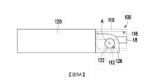
請參考圖2及圖3,在本實施例中,樞接組件100包括一第一連接部110及一第二連接部120。第一連接部110連接至前端組件12與第二鏡腳16其中的一個(本實施例以前端組件12為例)。第二連接部120連接至前端組件12與第二鏡腳16其中的另一個(本實施例以第二鏡腳16)為例。第一連接部110和第二連接部120的材料可為塑膠,以達成輕量化效果,但不以此為限。Referring to FIG. 2 and FIG. 3 , in this embodiment, the
在本實施例中,第一連接部110具有一第一上樞接部112及一第一下樞接部114。第二連接部120具有一第二上樞接部122及一第二下樞接部124。第一上樞接部112與第二上樞接部122在一樞轉軸線A上彼此配合,且第一下樞接部114與第二下樞接部124在樞轉軸線A上彼此配合,使得第二連接部120相對於第一連接部110在樞轉軸線A上樞轉。導線18從前端組件12延伸穿過第一上樞接部112或第二上樞接部122與第一下樞接部114或第二下樞接部124之間的空間而到達第二鏡腳16。In this embodiment, the first connecting
在本實施例中,第一上樞接部112及二上樞接部分別為彼此配合的一軸孔及一軸體,且第一下樞接部114及二下樞接部分別為彼此配合的另一軸孔及另一軸體。具體來說,第一上樞接部112及第一下樞接部114可為軸孔,而第二上樞接部122及第二下樞接部124可為軸體,但不以此為限。在另一未繪示的實施例中,第一上樞接部112及第二下樞接部124可為軸孔,而第二上樞接部122及第一下樞接部114均為軸體。在另一未繪示的實施例中,第一上樞接部112及第二下樞接部124可為軸體,而第二上樞接部122及第一下樞接部114分均為軸孔。在前述實施例中,當第一上樞接部112、第二上樞接部122、第一下樞接部114及第二下樞接部124其中的一個為軸體時,導線18在樞轉軸線A上朝向此軸體(即第一上樞接部112、第二上樞接部122、第一下樞接部114或第二下樞接部124)的投影落在此軸體上。前述的情況可見於圖6中的實施例中,即導線18在樞轉軸線A上朝向此軸體(即第二上樞接部122)的投影落在此軸體上,但不限於此。In this embodiment, the first
在本實施例中,當第一上樞接部112及第一下樞接部114為軸孔,且第二上樞接部122及第二下樞接部124為軸體時,這些軸孔(即第一上樞接部112及第一下樞接部114)的每一個具有一側向開口S。這些軸體(即第二上樞接部122及第二下樞接部124)分別經由這些側向開口S進入這些軸孔(即第一上樞接部112及第一下樞接部114)。此外,樞接組件100還包括一限位件130,其僅繪示於圖2及圖3。限位件130包括多個限位部130a。這些限位部130a分別封閉這些側向開口S,以將這些軸體(即第二上樞接部122及第二下樞接部124)分別限位在這些軸孔(即第一上樞接部112及第一下樞接部114)內。在另一未繪示的實施例中,這些側向開口S可形成頸縮結構,使得這些軸體(即第二上樞接部122及第二下樞接部124)分別經由這些側向開口S被迫進入這些軸孔(即第一上樞接部112及第一下樞接部114),而被限制在這些軸孔(即第一上樞接部112及第一下樞接部114)內。In this embodiment, when the first
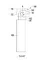
在圖5A及圖5B中,第一連接部110以透明及虛線方式呈現。在圖6中,第一連接部110及第二連接部120以透明及不同斷線方式呈現。In Fig. 5A and Fig. 5B, the
在本實施例中,處於圖4A及圖5A的打開狀態的樞接組件100的第二連接部120可相對於第一連接部110受力經由第一上樞接部112和第二上樞接部122之間的配合以及第一下樞接部114和第二下樞接部124之間的配合相對於第一連接部110樞轉至圖4B及圖5B的關閉狀態,使得圖1的第二鏡腳16可對應第一連接部110和第二連接部120之間的相對樞轉而被折疊靠近前端組件12。同時,導線18可對應第一連接部110和第二連接部120之間的樞轉而自然彎曲,如圖6所示。具體而言,由於導線18延伸於軸體之間的空間而不需靠著軸體延伸,所以導線18原先繞過軸體的區段在樞轉過程中不再被拉扯而可自然彎曲,這延長了導線18的使用壽命。In this embodiment, the
請參考圖2及圖3,在本實施例中,第一連接部110可具有一凹槽116。第二連接部120可具有一槽殼126。槽殼126可位於凹槽116內。導線18可延伸於槽殼126內。第一上樞接部112和第一下樞接部114可位於凹槽116的兩側。第二上樞接部122和第二下樞接部124可位於槽殼126的兩側。槽殼126可對應可對應第一連接部110和第二連接部120之間的樞轉而在凹槽116內移動。2 and 3 , in this embodiment, the
綜上所述,在本發明中,將用於樞轉的軸體分成有間隔的兩部分以讓導線延伸經過,這有利於減少外觀尺寸,並可讓導線可自然彎曲以延長使用壽命。In summary, in the present invention, the shaft for pivoting is divided into two spaced parts to allow the wire to extend through, which is beneficial to reducing the external dimensions and allows the wire to bend naturally to extend the service life.
10:眼鏡型顯示裝置 12:前端組件 14:第一鏡腳 16:第二鏡腳 18:導線 100:樞接組件 110:第一連接部 112:第一上樞接部 114:第一下樞接部 116:凹槽 120:第二連接部 122:第二上樞接部 124:第二下樞接部 126:槽殼 130:限位件 130a:限位部 A:樞轉軸線 S:側向開口10: Eyeglass-type display device12: Front end assembly14: First mirror leg16: Second mirror leg18: Wire100: Pivot assembly110: First connecting portion112: First upper pivot portion114: First lower pivot portion116: Groove120: Second connecting portion122: Second upper pivot portion124: Second lower pivot portion126: Slot shell130: Limiting
圖1是依照本發明的一實施例的一種眼鏡型顯示裝置的示意圖。 圖2是圖1的樞接組件的分解圖。 圖3是圖2的樞接組件的組合圖。 圖4A是圖1的樞接組件於打開狀態的立體圖。 圖4B是圖4A的樞接組件於打開狀態的立體圖。 圖5A是圖1的樞接組件於關閉狀態的俯視圖。 圖5B是圖5A的樞接組件於關閉狀態的俯視圖。 圖6是圖5B的樞接組件表示導線彎曲狀態的俯視圖。FIG. 1 is a schematic diagram of a spectacle-type display device according to an embodiment of the present invention.FIG. 2 is an exploded view of the hinge assembly of FIG. 1.FIG. 3 is an assembled view of the hinge assembly of FIG. 2.FIG. 4A is a three-dimensional view of the hinge assembly of FIG. 1 in an open state.FIG. 4B is a three-dimensional view of the hinge assembly of FIG. 4A in an open state.FIG. 5A is a top view of the hinge assembly of FIG. 1 in a closed state.FIG. 5B is a top view of the hinge assembly of FIG. 5A in a closed state.FIG. 6 is a top view of the hinge assembly of FIG. 5B showing a wire bending state.
10:眼鏡型顯示裝置10: Eyeglass-type display device
12:前端組件12: Front-end components
14:第一鏡腳14: First scene
16:第二鏡腳16: Second scene
18:導線18: Wire
100:樞接組件100: hinge assembly
110:第一連接部110: First connection part
120:第二連接部120: Second connection part
Claims (5)
Translated fromChineseApplications Claiming Priority (2)
| Application Number | Priority Date | Filing Date | Title |
|---|---|---|---|
| US202263432041P | 2022-12-12 | 2022-12-12 | |
| US63/432,041 | 2022-12-12 |
Publications (2)
| Publication Number | Publication Date |
|---|---|
| TW202424586A TW202424586A (en) | 2024-06-16 |
| TWI871041Btrue TWI871041B (en) | 2025-01-21 |
Family
ID=91382245
Family Applications (1)
| Application Number | Title | Priority Date | Filing Date |
|---|---|---|---|
| TW112138645ATWI871041B (en) | 2022-12-12 | 2023-10-11 | Glasses type display device |
Country Status (3)
| Country | Link |
|---|---|
| US (1) | US12222585B2 (en) |
| CN (1) | CN118192084A (en) |
| TW (1) | TWI871041B (en) |
Citations (4)
| Publication number | Priority date | Publication date | Assignee | Title |
|---|---|---|---|---|
| CN2784967Y (en)* | 2005-02-06 | 2006-05-31 | 珠海精准电子有限公司 | Durable multifunctional glasses |
| CN210123499U (en)* | 2019-05-28 | 2020-03-03 | 优奈柯恩(北京)科技有限公司 | Augmented reality glasses |
| US10761346B1 (en)* | 2015-12-28 | 2020-09-01 | Amazon Technologies, Inc. | Head-mounted computer device with hinge |
| CN211577564U (en)* | 2020-03-24 | 2020-09-25 | 联想(北京)有限公司 | Glasses |
Family Cites Families (8)
| Publication number | Priority date | Publication date | Assignee | Title |
|---|---|---|---|---|
| IT1275030B (en)* | 1994-06-27 | 1997-07-29 | Killer Loop Spa | INTERCONNECTION AND LOCKING DEVICE OF TWO GLASSES OR PROTECTIVE ELEMENTS FOR SPORT |
| US6007198A (en)* | 1998-12-23 | 1999-12-28 | Burton; Jesse L. | Rear-view mirror for attachment to eyeglasses and cap brims |
| US6163926A (en)* | 1999-11-12 | 2000-12-26 | Ppg Industries Ohio, Inc. | Split-pin hinge with wire extending therethrough |
| ATE241158T1 (en)* | 2000-12-21 | 2003-06-15 | F A Thiele As | GLASSES FRAME AND ASSOCIATED HINGE ARRANGEMENT |
| GB0712036D0 (en)* | 2007-06-21 | 2007-08-01 | Airspirit Ltd | Hinge arrangement for spectacles |
| US8371692B2 (en)* | 2009-10-28 | 2013-02-12 | Micron Eyewear Manufactory Company Limited | Pinless hinge for eyewear |
| GB2477264B (en)* | 2010-01-18 | 2015-02-25 | Gici Labs Llp | Eyeglasses and means for their adjustment |
| CN109782447B (en) | 2019-02-15 | 2021-10-15 | 华为技术有限公司 | Wearable device |
- 2023
- 2023-10-11CNCN202311313736.XApatent/CN118192084A/enactivePending
- 2023-10-11TWTW112138645Apatent/TWI871041B/enactive
- 2023-10-11USUS18/484,457patent/US12222585B2/enactiveActive
Patent Citations (4)
| Publication number | Priority date | Publication date | Assignee | Title |
|---|---|---|---|---|
| CN2784967Y (en)* | 2005-02-06 | 2006-05-31 | 珠海精准电子有限公司 | Durable multifunctional glasses |
| US10761346B1 (en)* | 2015-12-28 | 2020-09-01 | Amazon Technologies, Inc. | Head-mounted computer device with hinge |
| CN210123499U (en)* | 2019-05-28 | 2020-03-03 | 优奈柯恩(北京)科技有限公司 | Augmented reality glasses |
| CN211577564U (en)* | 2020-03-24 | 2020-09-25 | 联想(北京)有限公司 | Glasses |
Also Published As
| Publication number | Publication date |
|---|---|
| TW202424586A (en) | 2024-06-16 |
| US20240192521A1 (en) | 2024-06-13 |
| CN118192084A (en) | 2024-06-14 |
| US12222585B2 (en) | 2025-02-11 |
Similar Documents
| Publication | Publication Date | Title |
|---|---|---|
| CN102628995B (en) | Virtual image display apparatus | |
| KR102734308B1 (en) | Electronic device including heat radiation member | |
| US11372251B2 (en) | Systems, devices, and methods for electrical pathways between components in wearable heads-up displays | |
| US20170108714A1 (en) | Wearable electronic display | |
| EP3894981B1 (en) | Modular accessory systems for wearable devices | |
| US20220210922A1 (en) | Flexible printed circuit board and electronic device including flexible printed circuit board | |
| US20220287180A1 (en) | Electronic device including flexible printed circuit board | |
| CN114236848B (en) | Mounting module, externally hung device and head-mounted equipment | |
| US20170090200A1 (en) | Display device and head mounted display | |
| US11992102B2 (en) | Case for electronic device | |
| EP1720058A1 (en) | Image display device | |
| CN116774443A (en) | smart glasses | |
| TWI871041B (en) | Glasses type display device | |
| CN114527570A (en) | Near-to-eye display optical system and head-mounted equipment | |
| CN114153069B (en) | Glasses type display device | |
| CN217112896U (en) | Picture frame, head-mounted assembly and head-mounted equipment | |
| CN114280789B (en) | Near-eye display optical system and near-eye display optical apparatus | |
| WO2023040542A1 (en) | Head-mounted device | |
| KR20240004083A (en) | Wearable electronic device including a lens assembly | |
| CN216210239U (en) | Elasticity adjusting part and head-mounted equipment | |
| WO2023279796A1 (en) | Head-mounted device | |
| CN115586646B (en) | Head-mounted device | |
| CN218497273U (en) | AR (augmented reality) glasses frame and AR glasses | |
| CN216670404U (en) | Elasticity adjusting part and head-mounted equipment | |
| CN219456644U (en) | Video glasses |