TWI868462B - Display with stacked light-guide elements providing different parts of field of view - Google Patents
Display with stacked light-guide elements providing different parts of field of viewDownload PDFInfo
- Publication number
- TWI868462B TWI868462BTW111125003ATW111125003ATWI868462BTW I868462 BTWI868462 BTW I868462BTW 111125003 ATW111125003 ATW 111125003ATW 111125003 ATW111125003 ATW 111125003ATW I868462 BTWI868462 BTW I868462B
- Authority
- TW
- Taiwan
- Prior art keywords
- optical element
- light
- light guide
- partially reflective
- image
- Prior art date
Links
- 238000005286illuminationMethods0.000claimsabstractdescription46
- 230000003287optical effectEffects0.000claimsdescription109
- 239000002131composite materialSubstances0.000claimsdescription21
- 238000010168coupling processMethods0.000claimsdescription18
- 238000005859coupling reactionMethods0.000claimsdescription18
- 230000008878couplingEffects0.000claimsdescription17
- 230000001902propagating effectEffects0.000claimsdescription15
- 238000000576coating methodMethods0.000claimsdescription14
- 239000011248coating agentSubstances0.000claimsdescription13
- 239000012780transparent materialSubstances0.000claimsdescription13
- 239000000463materialSubstances0.000claimsdescription8
- 238000002310reflectometryMethods0.000claimsdescription8
- 239000006117anti-reflective coatingSubstances0.000claimsdescription5
- 230000007246mechanismEffects0.000claimsdescription5
- 150000001875compoundsChemical class0.000abstract3
- 239000010410layerSubstances0.000description9
- 238000000034methodMethods0.000description6
- 230000003667anti-reflective effectEffects0.000description4
- 101100233916Saccharomyces cerevisiae (strain ATCC 204508 / S288c) KAR5 geneProteins0.000description3
- 230000008901benefitEffects0.000description3
- 239000012790adhesive layerSubstances0.000description2
- 238000003491arrayMethods0.000description2
- 230000004424eye movementEffects0.000description2
- 230000000644propagated effectEffects0.000description2
- XUIMIQQOPSSXEZ-UHFFFAOYSA-NSiliconChemical compound[Si]XUIMIQQOPSSXEZ-UHFFFAOYSA-N0.000description1
- 239000000853adhesiveSubstances0.000description1
- 238000004026adhesive bondingMethods0.000description1
- 230000001070adhesive effectEffects0.000description1
- 239000003086colorantSubstances0.000description1
- 238000009826distributionMethods0.000description1
- 239000011521glassSubstances0.000description1
- 239000004973liquid crystal related substanceSubstances0.000description1
- 238000004519manufacturing processMethods0.000description1
- 238000000926separation methodMethods0.000description1
- 229910052710siliconInorganic materials0.000description1
- 239000010703siliconSubstances0.000description1
- 239000000758substrateSubstances0.000description1
- 238000002834transmittanceMethods0.000description1
Images


Classifications
- G—PHYSICS
- G02—OPTICS
- G02B—OPTICAL ELEMENTS, SYSTEMS OR APPARATUS
- G02B27/00—Optical systems or apparatus not provided for by any of the groups G02B1/00 - G02B26/00, G02B30/00
- G02B27/01—Head-up displays
- G02B27/0101—Head-up displays characterised by optical features
- G—PHYSICS
- G02—OPTICS
- G02B—OPTICAL ELEMENTS, SYSTEMS OR APPARATUS
- G02B6/00—Light guides; Structural details of arrangements comprising light guides and other optical elements, e.g. couplings
- G02B6/0001—Light guides; Structural details of arrangements comprising light guides and other optical elements, e.g. couplings specially adapted for lighting devices or systems
- G02B6/0011—Light guides; Structural details of arrangements comprising light guides and other optical elements, e.g. couplings specially adapted for lighting devices or systems the light guides being planar or of plate-like form
- G02B6/0013—Means for improving the coupling-in of light from the light source into the light guide
- G02B6/0015—Means for improving the coupling-in of light from the light source into the light guide provided on the surface of the light guide or in the bulk of it
- G02B6/0018—Redirecting means on the surface of the light guide
- G—PHYSICS
- G02—OPTICS
- G02B—OPTICAL ELEMENTS, SYSTEMS OR APPARATUS
- G02B6/00—Light guides; Structural details of arrangements comprising light guides and other optical elements, e.g. couplings
- G02B6/0001—Light guides; Structural details of arrangements comprising light guides and other optical elements, e.g. couplings specially adapted for lighting devices or systems
- G02B6/0011—Light guides; Structural details of arrangements comprising light guides and other optical elements, e.g. couplings specially adapted for lighting devices or systems the light guides being planar or of plate-like form
- G02B6/0013—Means for improving the coupling-in of light from the light source into the light guide
- G02B6/0023—Means for improving the coupling-in of light from the light source into the light guide provided by one optical element, or plurality thereof, placed between the light guide and the light source, or around the light source
- G02B6/0031—Reflecting element, sheet or layer
- G—PHYSICS
- G02—OPTICS
- G02B—OPTICAL ELEMENTS, SYSTEMS OR APPARATUS
- G02B6/00—Light guides; Structural details of arrangements comprising light guides and other optical elements, e.g. couplings
- G02B6/0001—Light guides; Structural details of arrangements comprising light guides and other optical elements, e.g. couplings specially adapted for lighting devices or systems
- G02B6/0011—Light guides; Structural details of arrangements comprising light guides and other optical elements, e.g. couplings specially adapted for lighting devices or systems the light guides being planar or of plate-like form
- G02B6/0033—Means for improving the coupling-out of light from the light guide
- G02B6/0035—Means for improving the coupling-out of light from the light guide provided on the surface of the light guide or in the bulk of it
- G02B6/0038—Linear indentations or grooves, e.g. arc-shaped grooves or meandering grooves, extending over the full length or width of the light guide
- G—PHYSICS
- G02—OPTICS
- G02B—OPTICAL ELEMENTS, SYSTEMS OR APPARATUS
- G02B6/00—Light guides; Structural details of arrangements comprising light guides and other optical elements, e.g. couplings
- G02B6/0001—Light guides; Structural details of arrangements comprising light guides and other optical elements, e.g. couplings specially adapted for lighting devices or systems
- G02B6/0011—Light guides; Structural details of arrangements comprising light guides and other optical elements, e.g. couplings specially adapted for lighting devices or systems the light guides being planar or of plate-like form
- G02B6/0075—Arrangements of multiple light guides
- G02B6/0076—Stacked arrangements of multiple light guides of the same or different cross-sectional area
- G—PHYSICS
- G02—OPTICS
- G02B—OPTICAL ELEMENTS, SYSTEMS OR APPARATUS
- G02B27/00—Optical systems or apparatus not provided for by any of the groups G02B1/00 - G02B26/00, G02B30/00
- G02B27/01—Head-up displays
- G02B27/0101—Head-up displays characterised by optical features
- G02B2027/0118—Head-up displays characterised by optical features comprising devices for improving the contrast of the display / brillance control visibility
- G02B2027/012—Head-up displays characterised by optical features comprising devices for improving the contrast of the display / brillance control visibility comprising devices for attenuating parasitic image effects
- G—PHYSICS
- G02—OPTICS
- G02B—OPTICAL ELEMENTS, SYSTEMS OR APPARATUS
- G02B27/00—Optical systems or apparatus not provided for by any of the groups G02B1/00 - G02B26/00, G02B30/00
- G02B27/01—Head-up displays
- G02B27/0101—Head-up displays characterised by optical features
- G02B2027/0123—Head-up displays characterised by optical features comprising devices increasing the field of view
- G—PHYSICS
- G02—OPTICS
- G02B—OPTICAL ELEMENTS, SYSTEMS OR APPARATUS
- G02B6/00—Light guides; Structural details of arrangements comprising light guides and other optical elements, e.g. couplings
- G02B6/0001—Light guides; Structural details of arrangements comprising light guides and other optical elements, e.g. couplings specially adapted for lighting devices or systems
- G02B6/0011—Light guides; Structural details of arrangements comprising light guides and other optical elements, e.g. couplings specially adapted for lighting devices or systems the light guides being planar or of plate-like form
- G02B6/0033—Means for improving the coupling-out of light from the light guide
- G02B6/0035—Means for improving the coupling-out of light from the light guide provided on the surface of the light guide or in the bulk of it
Landscapes
- Physics & Mathematics (AREA)
- General Physics & Mathematics (AREA)
- Optics & Photonics (AREA)
- Optical Elements Other Than Lenses (AREA)
- Light Guides In General And Applications Therefor (AREA)
- Illuminated Signs And Luminous Advertising (AREA)
Abstract
Description
Translated fromChinese本發明涉及顯示器,並且特別地,本發明涉及提供圖像視場的不同部分的具有堆疊光導光學元件的顯示器。The present invention relates to displays and, in particular, to displays having stacked light-guiding optical elements that provide different portions of an image field of view.
某些平視顯示器特別是近眼顯示器採用光導光學元件(Light-guide Optical Element,LOE),光導光學元件形成為透明材料塊,該透明材料塊具有通過內反射引導光的平行外部主表面,並且具有與主表面成斜角的一組部分反射內表面。准直圖像由圖像投影儀生成並且被注入到LOE(也稱為“波導”或“基板”)中,以通過內反射在LOE內傳播,直到由部分反射內表面朝向使用者的眼睛將准直圖像逐步地耦出。這種波導的示例可以在專利合作條約(Patent Cooperation Treaty,PCT)專利申請公佈第WO 03081320 A1號中找到。Some head-up displays, especially near-eye displays, employ a light-guide optical element (LOE) formed as a block of transparent material having parallel outer major surfaces that guide light by internal reflection and having a set of partially reflective inner surfaces at an oblique angle to the major surfaces. A collimated image is generated by an image projector and injected into the LOE (also called a "waveguide" or "substrate") to propagate within the LOE by internal reflection until the collimated image is progressively coupled out by the partially reflective inner surfaces toward the user's eyes. An example of such a waveguide can be found in Patent Cooperation Treaty (PCT) Patent Application Publication No. WO 03081320 A1.
通過這樣的佈置可以顯示的視場的角尺寸受到幾何光學考慮因素的限制,該幾何光學考慮因素例如是可以被捕獲在波導內以通過內反射傳播的角度範圍以及避免圖像及其在波導內的共軛之間的交疊。The angular size of the field of view that can be displayed by such an arrangement is limited by geometrical considerations such as the range of angles that can be captured within the waveguide to propagate by internal reflections and avoiding overlap between the image and its conjugates within the waveguide.
本發明是一種用於向使用者的眼睛提供圖像的顯示器。The present invention is a display for providing an image to the user's eyes.
根據本發明的實施方式的教導,提供了一種用於向使用者的眼睛提供圖像的顯示器,該顯示器包括:(a)複合光導裝置,包括:(i)第一光導光學元件,該第一光導光學元件包括透明材料塊,該透明材料塊具有一對相互平行的主表面,用於通過主表面處的內反射來引導光,以及(ii)第二光導光學元件,該第二光導光學元件包括透明材料塊,該透明材料塊具有一對相互平行的主表面,用於通過主表面處的內反射來引導光,第一光導光學元件和第二光導光學元件以主表面並置的方式堆疊;以及(b)圖像投影儀,其被配置成投影與具有角視場的准直圖像對應的圖像照明,圖像投影儀光學地耦合至複合光導裝置,以引入通過內反射在第一光導光學元件內傳播的圖像照明的第一部分以及通過內反射在第二光導光學元件內傳播的圖像照明的第二部分,其中,第一光導光學元件包括第一耦出配置,第一耦出配置包括第一多個相互平行的部分反射表面,第一多個部分反射表面部署在第一光導光學元件的主表面之間並且相對於主表面傾斜地成角度,第一多個部分反射表面位於複合光導裝置的第一區域中,用於耦出圖像照明的視場的第一部分供用戶的眼睛觀看,並且其中,第二光導光學元件包括第二耦出配置,第二耦出配置包括第二多個相互平行的部分反射表面,第二多個部分反射表面部署在第二光導光學元件的主表面之間並且相對於主表面傾斜地成角度,第二多個部分反射表面不平行於第一多個部分反射表面,並且第二多個部分反射表面位於複合光導裝置的與第一區域至少部分地不交疊的第二區域中,用於耦出圖像照明的視場的第二部分供使用者的眼睛觀看,並且其中,圖像投影儀向複合光導裝置的光學耦合以及第一多個部分反射表面和第二多個部分反射表面的部署使得:從圖像投影儀平行出射並且分別地耦合到第一光導光學元件和第二光導光學元件中的第一圖像照明光線和第二圖像照明光線在第一光導光學元件和第二光導光學元件內以不同角度傳播,但是由第一多個部分反射表面和第二多個部分反射表面分別耦出成為平行光線。According to the teachings of the embodiments of the present invention, a display for providing an image to a user's eye is provided, the display comprising: (a) a composite light guide device, comprising: (i) a first light guide optical element, the first light guide optical element comprising a transparent material block, the transparent material block having a pair of mutually parallel major surfaces, for guiding light by internal reflection at the major surfaces, and (ii) a second light guide optical element, the second light guide optical element comprising a transparent material block, the transparent material block having a pair of mutually parallel major surfaces, for guiding light by internal reflection at the major surfaces, the first light guide optical element and the second light guide optical element optical elements stacked in major surface juxtaposition; and (b) an image projector configured to project image illumination corresponding to a collimated image having an angular field of view, the image projector optically coupled to the composite light guide device to introduce a first portion of the image illumination propagated by internal reflection within a first light guide optical element and a second portion of the image illumination propagated by internal reflection within a second light guide optical element, wherein the first light guide optical element includes a first outcoupling configuration, the first outcoupling configuration including a first plurality of mutually parallel partially reflective surfaces disposed between and relative to the major surfaces of the first light guide optical element The optical element of the present invention is characterized in that the optical element has a first plurality of partially reflective surfaces disposed between the major surfaces of the second optical element and angled obliquely relative to the major surfaces, the first plurality of partially reflective surfaces are located in a first region of the composite light guide device for coupling out a first portion of the field of view of the image illumination for viewing by an eye of a user, and wherein the second light guide optical element includes a second outcoupling configuration, the second outcoupling configuration includes a second plurality of mutually parallel partially reflective surfaces, the second plurality of partially reflective surfaces are disposed between the major surfaces of the second light guide optical element and angled obliquely relative to the major surfaces, the second plurality of partially reflective surfaces are not parallel to the first plurality of partially reflective surfaces, and the second plurality of partially reflective surfaces are located in a first region of the composite light guide device that is at least partially adjacent to the first region. In the second area that does not overlap, the second part of the field of view for coupling out the image illumination is for viewing by the user's eyes, and wherein the optical coupling of the image projector to the composite light guide device and the deployment of the first plurality of partially reflecting surfaces and the second plurality of partially reflecting surfaces enable: the first image illumination light and the second image illumination light emitted in parallel from the image projector and coupled into the first light guide optical element and the second light guide optical element, respectively, propagate at different angles in the first light guide optical element and the second light guide optical element, but are coupled out by the first plurality of partially reflecting surfaces and the second plurality of partially reflecting surfaces, respectively, into parallel light.
根據本發明的實施方式的另一特徵,圖像投影儀經由主表面之一將圖像照明注入到複合光導裝置中,並且其中,圖像照明的第一部分通過第一反射器耦合到第一光導光學元件中,並且圖像照明的第二部分通過第二反射器耦合到第二光導光學元件中。According to another feature of an embodiment of the invention, the image projector injects image illumination into the composite light guide via one of the main surfaces, and wherein a first portion of the image illumination is coupled into the first light guide optical element via a first reflector, and a second portion of the image illumination is coupled into the second light guide optical element via a second reflector.
根據本發明的實施方式的另一特徵,第一反射器和第二反射器不平行。According to another feature of an embodiment of the present invention, the first reflector and the second reflector are not parallel.
根據本發明的實施方式的另一特徵,第一反射器和第二反射器是呈非交疊關係的全反射器。According to another feature of the implementation of the present invention, the first reflector and the second reflector are total reflectors in a non-overlapping relationship.
根據本發明的實施方式的另一特徵,第二反射器是部分反射器,並且其中,光在穿過第二反射器之後到達第一反射器。According to another feature of an embodiment of the present invention, the second reflector is a partial reflector, and wherein the light reaches the first reflector after passing through the second reflector.
根據本發明的實施方式的另一特徵,第二反射器在第二光導光學元件的內部,並且其中,第一反射器與棱鏡的表面相關聯,所述棱鏡附接至第一光導光學元件的距離圖像投影儀較遠的主表面。According to another feature of an embodiment of the invention, the second reflector is inside the second light-guiding optical element, and wherein the first reflector is associated with a surface of a prism attached to a main surface of the first light-guiding optical element that is farther from the image projector.
根據本發明的實施方式的另一特徵,還提供了調整機構,用於允許對第一反射器的角度進行微調整。According to another feature of an embodiment of the present invention, an adjustment mechanism is also provided to allow fine adjustment of the angle of the first reflector.
根據本發明的實施方式的另一特徵,第一光導光學元件和第二光導光學元件由氣隙隔開。According to another feature of an embodiment of the present invention, the first light-guiding optical element and the second light-guiding optical element are separated by an air gap.
根據本發明的實施方式的另一特徵,第一光導光學元件和第二光導光學元件的透明材料具有第一折射率,並且其中,第一光導光學元件和第二光導光學元件由具有第二折射率的材料層隔開,第二折射率低於第一折射率。According to another feature of an embodiment of the present invention, the transparent material of the first light-guiding optical element and the second light-guiding optical element has a first refractive index, and wherein the first light-guiding optical element and the second light-guiding optical element are separated by a material layer having a second refractive index, the second refractive index being lower than the first refractive index.
根據本發明的實施方式的另一特徵,並置主表面中的每一個設置有抗反射塗層。According to another feature of an embodiment of the present invention, each of the juxtaposed main surfaces is provided with an anti-reflective coating.
根據本發明的實施方式的另一特徵,第一光導光學元件和第二光導光學元件的並置主表面中的至少一個設置有角度選擇性多層介電塗層,該角度選擇性多層介電塗層被配置成對於相對於主表面的法線大於60度的入射角是完全反射的,並且對於相對於法線小於15度的入射角具有低反射率。According to another feature of an embodiment of the present invention, at least one of the juxtaposed main surfaces of the first light-guiding optical element and the second light-guiding optical element is provided with an angle-selective multilayer dielectric coating, which is configured to be completely reflective for an incident angle greater than 60 degrees relative to the normal of the main surface and to have a low reflectivity for an incident angle less than 15 degrees relative to the normal.
根據本發明的實施方式的另一特徵,第一光導光學元件包括第一組相互平行的部分反射偏轉表面,第一組偏轉表面部署在第一光導光學元件的主表面之間,第一組偏轉表面被部署成使在第一光導光學元件內傳播的圖像照明的第一部分朝向第一多個部分反射表面逐漸偏轉,並且其中,第二光導光學元件包括第二組相互平行的部分反射偏轉表面,第二組偏轉表面部署在第二光導光學元件的主表面之間,第二組偏轉表面被部署成使在第二光導光學元件內傳播的圖像照明的第二部分朝向第二多個部分反射表面漸進地偏轉。According to another feature of an embodiment of the present invention, the first light-guiding optical element comprises a first set of mutually parallel partially reflective deflecting surfaces, the first set of deflecting surfaces being disposed between the main surfaces of the first light-guiding optical element, the first set of deflecting surfaces being disposed to gradually deflect a first portion of the image illumination propagating in the first light-guiding optical element toward the first plurality of partially reflective surfaces, and wherein the second light-guiding optical element comprises a second set of mutually parallel partially reflective deflecting surfaces, the second set of deflecting surfaces being disposed between the main surfaces of the second light-guiding optical element, the second set of deflecting surfaces being disposed to gradually deflect a second portion of the image illumination propagating in the second light-guiding optical element toward the second plurality of partially reflective surfaces.
根據本發明實施方式的另一特徵,第一組偏轉表面的平面與主表面的相交線不平行於第二組偏轉表面的平面與主表面的相交線。According to another feature of the embodiment of the present invention, the intersection line between the plane of the first set of deflection surfaces and the main surface is not parallel to the intersection line between the plane of the second set of deflection surfaces and the main surface.
根據本發明的實施方式的另一特徵,第一光導光學元件包括第一內反射表面,第一內反射表面平行於第一組偏轉表面並且被部署成使在第一光導光學元件內傳播的圖像照明的第一部分朝向第一組偏轉表面偏轉,並且其中,第二光導光學元件包括第二內反射表面,第二內反射表面平行於第二組偏轉表面並且被部署成使在第二光導光學元件內傳播的圖像照明的第二部分朝向第二組偏轉表面偏轉。According to another feature of an embodiment of the present invention, the first light-guiding optical element comprises a first internal reflection surface, which is parallel to the first set of deflection surfaces and is arranged to deflect a first portion of the image illumination propagating in the first light-guiding optical element toward the first set of deflection surfaces, and wherein the second light-guiding optical element comprises a second internal reflection surface, which is parallel to the second set of deflection surfaces and is arranged to deflect a second portion of the image illumination propagating in the second light-guiding optical element toward the second set of deflection surfaces.
10:第一光導光學元件10: First light-guiding optical element
100:圖像投影儀100: Image projector
101:眼動框101: Eye movement frame
11,17,18,19,21,22,27,28,29,121,122,123,124,141:表面11,17,18,19,21,22,27,28,29,121,122,123,124,141: Surface
12:表面/第一反射器12: Surface/first reflector
120:棱鏡120: Prism
13,14,23,24:主表面13,14,23,24: Main surface
130,140:窗130,140: Window
15:第一光線15: First Light
16,26:光線16,26: Light
19,29:內表面19,29: Inner surface
20:第二光導光學元件20: Second light-guiding optical element
22:第二反射器22: Second reflector
25:第二光線25: Second Ray
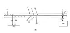
在本文中參照圖式僅以示例的方式來描述本發明,在圖式中:圖1是根據本發明的實施方式的教導構造和操作的顯示器的示意性側視圖,顯示器採用光導光學元件(LOE)的堆疊來將圖像從投影儀傳送至用戶的眼睛,其中,每個LOE傳送視場的不同部分;圖2是類似於圖1的視圖,示出了其中耦入光線不平行於耦出光線而投影圖像的平行圖像光線在耦出圖像中保持平行的實現方式;圖3是類似於圖1的視圖,示出了通過使用交疊的部分反射的耦入反射器實現的減小尺寸的耦入孔徑;圖4A是類似於圖3的視圖,示出了在一個LOE上的外部棱鏡上的耦入反射器的實現方式;圖4B是類似於圖4A的視圖,其中外部棱鏡與外部反射器表面一起使用;圖4C是類似於圖4B的視圖,其中通過使用Risley楔形棱鏡對使外部反射器表面可調整;圖5A至圖5C分別是根據本發明的顯示器的另一實施方式的用於提供二維的孔徑擴展的第二LOE、第一LOE以及由第一LOE和第二LOE組裝的堆疊的正視圖;以及圖6A至圖6C分別是與圖5A至圖5C對應的側視圖。The present invention is described herein by way of example only with reference to the accompanying drawings in which: FIG. 1 is a schematic side view of a display constructed and operated in accordance with the teachings of an embodiment of the present invention, the display employing a stack of light-conducting optical elements (LOEs) to transmit an image from a projector to a user's eye, wherein each LOE transmits a different portion of the field of view; FIG. 2 is a view similar to FIG. 1 showing an implementation in which the in-coupled light rays are not parallel to the out-coupled light rays while the parallel image rays of the projected image remain parallel in the out-coupled image; FIG. 3 is a view similar to FIG. 1 showing a reduced size in-coupled aperture achieved by using overlapping partially reflective in-coupled reflectors; FIG. FIG. 4A is a view similar to FIG. 3, showing an implementation of an in-coupling reflector on an external prism on one LOE; FIG. 4B is a view similar to FIG. 4A, wherein an external prism is used together with an external reflector surface; FIG. 4C is a view similar to FIG. 4B, wherein the external reflector surface is adjustable by using a Risley wedge prism pair; FIG. 5A to FIG. 5C are front views of a second LOE, a first LOE, and a stack assembled by the first LOE and the second LOE for providing two-dimensional aperture expansion according to another embodiment of the display of the present invention; and FIG. 6A to FIG. 6C are side views corresponding to FIG. 5A to FIG. 5C, respectively.
本發明是一種用於向使用者的眼睛提供圖像的顯示器。The present invention is a display for providing an image to the user's eyes.
參照圖式和所附描述可以更好地理解根據本發明的顯示器的原理和操作。The principles and operation of the display according to the present invention may be better understood with reference to the drawings and the accompanying description.
現在參照圖式,圖1至圖5都示出了根據本發明的教導構造和操作的用於向使用者的眼睛提供圖像的顯示器的實現方式,其中假設眼睛位於由101指定的區域,稱為“眼動框”(Eye Motion Box,EMB),該區域表示顯示器被設計為提供完整圖像的眼睛位置的範圍。一般而言,顯示器包括複合光導裝置,複合光導裝置具有第一光導光學元件(“LOE”,可互換地稱為“波導”)10和第二光導光學元件20,其各自形成為具有一對相互平行的主表面(對於LOE 10為主表面13和主表面14,對於LOE 20為主表面23和主表面24)的透明材料的塊。Referring now to the drawings, FIGS. 1-5 all illustrate implementations of a display for providing images to a user's eye, constructed and operative in accordance with the teachings of the present invention, wherein the eye is assumed to be located in an area designated by 101, referred to as an "Eye Motion Box" (EMB), which represents the range of eye positions within which the display is designed to provide a complete image. Generally speaking, the display includes a composite light guide having a first light guide optical element ("LOE", interchangeably referred to as a "waveguide") 10 and a second light guide
兩個LOE 10和20以主表面14和主表面23並置的方式堆疊,使得兩個波導保持它們作為單獨波導的特性,從而通過主表面處的內反射來引導光在每個LOE內的傳播。這可以通過在並置表面之間保持氣隙、通過提供具有較低折射率的居間材料層(作為不同的材料片或低折射率黏合劑層)、或者通過在並置表面中的一個或兩個上提供模擬TIR特性的塗層(通常為多層介電塗層的形式)來實現。術語“並置”或“相鄰”用於涵蓋所有上述選項,無論主表面是由空氣空間隔開、由居間材料層隔開的非接觸式鄰近還是直接接觸。在所有情況下,對於以相對接近於垂直的角度穿過複合光導裝置的光,通常通過施加抗反射塗層來優選地保持相對高的透射率,以允許透過顯示器觀看外部場景。The two
被配置成投影與具有角視場的准直圖像對應的圖像照明的圖像投影儀100光學耦合至複合光導裝置,以引入圖像照明的第一部分以通過內反射在第一LOE 10內傳播以及引入圖像照明的第二部分以通過內反射在第二LOE 20內傳播。下文將討論用於將圖像投影儀100光學耦合至複合光導裝置的耦入裝置的各種實現方式。An
第一LOE 10包括第一耦出配置,第一耦出配置具有第一多個相互平行的部分反射表面11,第一多個部分反射表面11部署在主表面13與主表面14之間,並且相對於主表面13和主表面14傾斜地成角度。第一多個部分反射表面11位於複合光導裝置的第一區域中,以用於將圖像照明的視場的第一部分耦出以供用戶的眼睛觀看。The
第二LOE 20包括第二耦出配置,第二耦出配置具有第二多個相互平行的部分反射表面21,第二多個部分反射表面21部署在主表面23與主表面24之間,並且相對於主表面23和主表面24傾斜地成角度。第二多個部分反射表面21不平行於第一多個部分反射表面11,並且位於複合光導裝置的與第一區域至少部分地不交疊的第二區域中,以用於將圖像照明的視場的第二部分耦出以供使用者的眼睛觀看。The
圖像投影儀100向複合光導裝置的光學耦合以及第一多個部分反射表面11和第二多個部分反射表面21的部署使得:從圖像投影儀100平行地射出並且分別耦合到第一光導光學元件10和第二光導光學元件20中的圖像照明的第一光線15和圖像照明的第二光線25在第一光導光學元件和第二光導光學元件內以不同的角度傳播,但是分別由第一多個部分反射表面11和第二多個部分反射表面21耦出作為平行的光線16和光線26。The optical coupling of the
此時,已經理解的是,本發明提供了許多顯著的優點。具體地,由於每個波導僅需要傳送角視場的子區域,因此放鬆了對耦出配置的部分反射表面中採用的角度選擇性塗層和各種其他部件的設計要求。具體地,每個耦出表面優選地對處於與期望圖像對應的角度範圍的紅光、綠光和藍光是部分反射的,而對處於與共軛圖像對應的角度範圍的紅光、綠光和藍光是高度透明的(抗反射)。如果這些特性僅對於圖像的一部分視場是需要的,則設計要求顯著放鬆。附加地或替選地,由於TIR和/或重影(通過使圖像的跨越波導的中心平面的部分交錯並且在其自身上折疊,以及/或者由內表面反射以反射圖像的一部分使得與另一部分交疊(即,當傳送的圖像部分的一部分平行於部分反射耦出表面中的一個傳播時)而形成)的角度限制,顯示器可以被實現為傳送比單個波導所能傳送的視場更大的視場。在每個波導中,可以允許視野(Field of view,FOV)中的不需要由該波導遞送的部分超過這些角度限制(允許該部分逃脫TIR,或者圖像的該部分被折疊在其共軛上),而不影響在眼動框處可見的圖像的品質。At this point, it is understood that the present invention provides a number of significant advantages. Specifically, since each waveguide only needs to transmit a sub-region of the angular field of view, the design requirements for the angle-selective coating and various other components employed in the partially reflective surfaces of the outcoupling configuration are relaxed. Specifically, each outcoupling surface is preferably partially reflective for red, green, and blue light in the angular range corresponding to the desired image, and highly transparent (anti-reflective) for red, green, and blue light in the angular range corresponding to the conjugate image. If these properties are only required for a portion of the field of view of the image, the design requirements are significantly relaxed. Additionally or alternatively, a display may be implemented to deliver a larger field of view than a single waveguide can deliver due to angular limitations of TIR and/or ghosting (formed by causing portions of the image that span the center plane of the waveguide to stagger and fold on themselves, and/or by reflections from internal surfaces to reflect a portion of the image so that it overlaps with another portion (i.e., when a portion of the transmitted image portion propagates parallel to one of the partially reflective outcoupling surfaces)). In each waveguide, portions of the field of view (FOV) that are not required to be delivered by that waveguide may be allowed to exceed these angular limitations (allowing that portion to escape TIR, or that portion of the image to be folded on its conjugate) without affecting the quality of the image visible at the eye box.
同時,圖像的所有部分源自單個圖像投影儀的事實保持了低製造成本,並且簡化了在所顯示的圖像的不同部分之間保持對準的任務。本發明的這些和其他優點將由以下詳述的示例變得更清楚。At the same time, the fact that all parts of the image originate from a single image projector keeps manufacturing costs low and simplifies the task of maintaining alignment between the different parts of the displayed image. These and other advantages of the invention will become clearer from the examples detailed below.
現在轉到圖1,其示出了上述顯示器的實現方式,其中顯示器具有兩個LOE 10和LOE 20,LOE 10和LOE 20各自形成為透明材料(例如玻璃或具有足夠的折射率以支持波導傳播的其他材料)的板結構。如上所述,每個LOE具有兩個主平行表面13和14(對於第二LOE 20為主平行表面23和主平行表面24)、相對于主表面成斜角的具有部分反射塗層的一組內部平行表面11(對於第二LOE為內部平行表面21)。LOE可選地還包括與主表面平行的內表面19、內表面29,內表面19和內表面29具有部分反射以使輸出強度分佈均勻。該內表面的特別優選的實現方式是在波導的中間平面處的表面,該表面對於與在波導內傳播的圖像照明對應的角度範圍具有約50%的反射率,並且在更接近於垂直通過波導的視角處具有低反射率(抗反射)。Turning now to FIG. 1 , an implementation of the above-described display is shown, wherein the display has two LOEs 10 and 20, each formed as a plate structure of a transparent material (e.g., glass or other material having a sufficient refractive index to support waveguide propagation). As described above, each LOE has two main
與本發明的設備一起採用的圖像投影儀100(可互換地稱為“POD”)優選地被配置成生成准直圖像,即,在准直圖像中,每個圖像圖元的光是具有與圖元位置對應的角方向的、准直到無限遠的平行光束。因此,圖像照明跨越與二維角視場對應的角度範圍。圖像投影儀100包括至少一個光源,其通常被部署成照射諸如液晶覆矽(Liquid Crystal On Silicon,LCOS)晶片的空間光調製器。空間光調製器調製圖像的每個圖元的投影強度,從而生成圖像。替選地,圖像投影儀可以包括通常使用一個或更多個快速掃描鏡實現的掃描裝置,該掃描裝置跨投影儀的圖像平面掃描來自鐳射光源的照明,同時在逐圖元的基礎上隨著運動同步地改變光束的強度,從而針對每個圖元投影期望的強度。在這兩種情況下,提供准直光學器件以生成被准直到無限遠的輸出投影圖像。以上部件中的一些或全部通常佈置在一個或更多個偏振分束器(Polarizing Beam-Splitter,PBS)立方體或本領域所公知的其他棱鏡裝置的表面上。An image projector 100 (interchangeably referred to as a "POD") employed with the apparatus of the present invention is preferably configured to generate a collimated image, i.e., in a collimated image, the light for each image element is a parallel beam of light that is collimated to infinity, having an angular direction corresponding to the position of the element. Thus, the image illumination spans an angular range corresponding to a two-dimensional angular field of view. The
在此處示出的特別優選的實現方式中,圖像投影儀100經由主表面24之一將圖像照明注入到複合光導裝置中。在這種情況下,圖像照明的第一部分通過第一反射器12耦合到第一光導光學元件10中,並且圖像照明的第二部分通過第二反射器22被耦合到第二光導光學元件20中。In a particularly preferred implementation shown here, the
儘管表面11和表面21不平行並且耦入第一反射器12和耦入第二反射器22不平行,但是如果這些表面與LOE的主表面之間的絕對角度相等(即,表面12與表面14之間以及表面11與表面14之間的絕對角度相等,並且表面22與24表面之間以及表面21與表面24之間的角度同樣相等),則進入兩個LOE的平行光線15和光線25也將從內表面陣列平行地離開LOE(光線16和光線26)。儘管由每個LOE引導的FOV將由於傾斜內表面的不同角度而不同,但是上述情況也會發生。Although
此外,如圖2所示,即使輸入耦合表面和輸出耦合表面陣列不平行或者與主表面處於相同的絕對角度,只要對於兩個LOE而言角度差相同,則進入兩個LOE的平行光線15和光線25將從內部部分反射表面陣列也平行地離開LOE(光線16和光線26),儘管與它們進入的角度不同(即,在該圖中光線15和光線16不平行)。Furthermore, as shown in Figure 2, even if the input coupling surface and output coupling surface arrays are not parallel or at the same absolute angle to the primary surface, as long as the angle difference is the same for both LOEs, then parallel rays 15 and 25 entering both LOEs will also leave the LOEs (rays 16 and 26) from the internal partially reflecting surface arrays in parallel, despite being at different angles than they entered (i.e., rays 15 and 16 are not parallel in this figure).
在圖1和圖2的示例性實現方式中,第一反射器12和第二反射器22是呈非交疊關係的全反射器。在這種情況下,兩個LOE的輸入孔徑寬度大致等於各個輸入孔徑的總和。In the exemplary implementations of FIGS. 1 and 2 , the
在圖3所例示的一組替選實現方式中,第二反射器22是部分反射器,並且光在穿過第二反射器22之後到達第一反射器12。在圖3的情況下,第一反射器12和第二反射器22是集成在LOE內(即在對應主表面的平面之間)的內部反射器。輸入孔徑的空間交疊減小了總輸入孔徑寬度。對於該實現方式,對於更靠近圖像投影儀的LOE,耦入表面反射率應當設置為50%。因此,在圖3中,表面12和表面22交疊,並且表面22應當具有約50%的反射率。In one set of alternative implementations illustrated in FIG3 , the
在圖4A至圖4C所示的一組變型實現方式中,第二反射器22在第二LOE 20的內部,而第一反射器直接或間接地與棱鏡120的表面相關聯,該棱鏡120附接至第一LOE 120的距離圖像投影儀100較遠的主表面13。In one set of variant implementations shown in FIGS. 4A to 4C , the
具體地,在圖4A的情況下,棱鏡120被膠合至LOE 10,並且光被棱鏡120的表面121反射並耦合到LOE中。Specifically, in the case of FIG. 4A , the
在圖4B所示的另一選項中,代替直接形成在棱鏡上的反射表面,棱鏡120可以與用作“第一反射器”的外部反射表面122協作,使得光從棱鏡120出射、從外部表面122反射並且重新進入棱鏡120,以在LOE內部被引導,如圖4B所示,其中光線15經由棱鏡120被外部表面122反射到LOE 10中。在這種情況下,表面121可以設置有抗反射(Anti-reflection,AR)塗層。可選地,可以通過將一些相關聯的表面如表面123和表面124黏附至LOE 10和/或棱鏡120的非光學有效的區域(即,從圖像投影儀到達EMB的光在其傳播時不撞擊這些表面)來固定外部反射器表面122的定位。In another option shown in FIG4B , instead of a reflective surface formed directly on the prism, the
在某些特別優選的實現方式中,本發明的顯示器可以設置有用於允許對第一反射器的角度進行微調整的調整機構。因此,在圖4B的實現方式中,可以使用主動對準系統和過程來確保離開兩個LOE的光線的平行度。在這樣的對準過程中,將單個准直光束耦合到兩個LOE中。當通過部分反射內表面11和部分反射內表面21的陣列從LOE耦出時,還在輸出處測量光束。如果表面21與表面22之間的角度差不等於表面11與表面12之間的角度差,則離開LOE 10的光線將不平行於離開LOE 20的光線。如果如圖4B中那樣使用外部鏡,則可以使用適當的調整機構使鏡的俯仰(pitch)和偏航(yaw)傾斜,直到到達光線16與光線26之間的平行度,並且然後通過對表面123和表面124進行膠合來固定該位置,以保持反射器122的取向。In certain particularly preferred implementations, the display of the present invention may be provided with an adjustment mechanism useful for allowing fine adjustment of the angle of the first reflector. Thus, in the implementation of FIG. 4B , an active alignment system and process may be used to ensure parallelism of light leaving the two LOEs. In such an alignment process, a single collimated beam is coupled into the two LOEs. The beam is also measured at the output as it is coupled out of the LOEs through the array of partially reflective
此外,即使在如圖4A所示的具有集成反射表面121的棱鏡120的情況下,也可以通過提供一組可以臨時膠合至LOE 10的具有小角度差的可互換棱鏡來實現類似的主動對準過程,並且選擇光線16與光線26之間具有最接近角度差的棱鏡以永久膠合至LOE 10。Furthermore, even in the case of a
圖4C示出了用於調整LOE 10的第一反射器輸入耦合表面的取向的替選機構和對應方法。在這種情況下,在棱鏡120的頂部,膠合兩個楔形窗130和140。這兩個楔形窗用作Risley棱鏡對。典型的楔值(wedge value)將是1度並且表示為α。在圖式中,為了說明的清楚,誇大了角度。如果兩個楔形窗具有其如圖所示彼此相對定向的楔形,則反射外表面141平行於棱鏡120的外表面。通過相對於窗130旋轉窗140,棱鏡120的表面與反射表面141之間的角度可以變化多達2α。因此,通過連續旋轉棱鏡140,可以獲得該範圍內的任何極角(polar angle)。通過相對於棱鏡120的表面旋轉窗130(連同窗140),可以獲得方位角的調整。因此,通過適當地旋轉兩個楔形窗,可以獲得第一反射器表面141的任何期望的取向,從而促成如上所述的主動對準過程。然後通過任何適當的附接形式(通常通過使用光學黏合劑),將兩個楔形窗固定在它們的最佳位置。所有中間表面優選地設置有AR塗層,以使可能導致重影的不期望反射最小化。FIG4C shows an alternative mechanism and corresponding method for adjusting the orientation of the first reflector input coupling surface of
現在轉到圖5A至圖6C,儘管至此已經在在一個維度上執行圖像投影儀的光學孔徑的擴展的設備的背景下說明了本發明,但是本發明還可以被實現為在在兩個維度上執行孔徑擴展的LOE的背景下獲得益處。對於這樣的實現方式,第一光導光學元件10優選地包括部署在第一光導光學元件10的主表面13、主表面14之間的第一組相互平行的部分反射偏轉表面17。第一組偏轉表面17被部署成使在第一光導光學元件內傳播的圖像照明朝向第一多個部分反射表面11逐漸地偏轉。類似地,第二光導光學元件20包括部署在第二光導光學元件20的主表面23、主表面24之間的第二組相互平行的部分反射偏轉表面27。第二組偏轉表面27被部署成使在第二光導光學元件內傳播的圖像照明的部分朝向第二多個部分反射表面21逐漸地偏轉。Turning now to Figures 5A to 6C, although the present invention has been described so far in the context of an apparatus for performing expansion of the optical aperture of an image projector in one dimension, the present invention may also be implemented to benefit in the context of a LOE that performs aperture expansion in two dimensions. For such an implementation, the first light guide
在圖5A至圖6C的特別優選但非限制的示例性實現方式中,第一LOE 10包括第一內反射表面18,該第一內反射表面18平行於第一組偏轉表面17並且被部署成使在第一光導光學元件內傳播的圖像照明的部分朝向第一組偏轉表面偏轉。類似地,第二LOE 20包括第二內反射表面28,該第二內反射表面28平行於第二組偏轉表面27並且被部署成使在第二光導光學元件內傳播的圖像照明的部分朝向第二組偏轉表面偏轉。In a particularly preferred but non-limiting exemplary implementation of FIGS. 5A to 6C , the
為了簡化呈現,圖5A和圖6A分別示出了第二LOE 20的前視圖和側視圖,圖5B和圖6B示出了第一LOE 10的類似視圖,並且圖5C和圖6C示出了經組裝的顯示器的對應視圖。第二LOE 20的特徵以虛線示出以有助於區分堆疊時的特徵。To simplify presentation, FIGS. 5A and 6A show front and side views, respectively, of the
因此,除了由圖1至圖4C的結構實現的LOE在X方向上的孔徑擴展之外,該實施方式還實現了沿Y方向的附加孔徑擴展維度。偏轉表面17和偏轉表面27是部分反射表面,而內反射表面18和內反射表面28平行於它們各自的偏轉表面但優選是全反射器。通過表面22從圖像投影儀100耦入以由第二LOE 20引導的光被表面28反射,以朝向偏轉表面27偏轉,在偏轉表面27處光被表面27逐漸地偏轉和反射。由於表面27和表面28都是平行的,來自陣列的表面27的最終偏轉光線將平行於由表面22耦合到LOE中的光。這同樣適用於由LOE 10內的表面18和表面17偏轉的光線。因此,儘管表面27和表面17可以不平行,但是耦合到第一LOE 10和第二LOE 20中的平行光線仍然可以平行地射出。Thus, in addition to the aperture expansion of the LOE in the X direction achieved by the structures of Figures 1 to 4C, this embodiment also achieves an additional aperture expansion dimension along the Y direction. Deflection surfaces 17 and 27 are partially reflective surfaces, while internal reflection surfaces 18 and 28 are parallel to their respective deflection surfaces but are preferably total reflectors. Light coupled in from the
在某些實現方式中,第一組偏轉表面17的平面與主表面13、主表面14的相交線不平行於第二組偏轉表面27的平面與主表面的相交線。In some implementations, the intersection line between the plane of the first set of deflection surfaces 17 and the
在某些實現方式中,第一組偏轉表面17和/或第二組偏轉表面27與LOE的主表面正交。在這種情況下,引導圖像及其共軛均被這些表面偏轉並且被朝向耦出區域重定向。在替選實現方式中,第一組偏轉表面17和/或第二組偏轉表面27相對於LOE的主表面傾斜。在這種情況下,僅一種圖像(主圖像或者其共軛)被朝向耦出區域逐漸地偏轉,而表面優選地在與不期望的圖像對應的入射角的範圍內基本上透明。In some implementations, the first set of deflection surfaces 17 and/or the second set of deflection surfaces 27 are orthogonal to the main surface of the LOE. In this case, both the guide image and its conjugate are deflected by these surfaces and redirected towards the outcoupling region. In an alternative implementation, the first set of deflection surfaces 17 and/or the second set of deflection surfaces 27 are tilted relative to the main surface of the LOE. In this case, only one image (the main image or its conjugate) is gradually deflected towards the outcoupling region, while the surfaces are preferably substantially transparent in the range of angles of incidence corresponding to the undesired image.
實現方式細節──塗層Implementation details – coating
為了最佳地實現本文中描述的各種實施方式,最優選地向元件之間的各種表面和介面賦予角度選擇特性。這些特性可以使用用於設計和實現多層介電塗層的成熟技術方便地生成,其中特定厚度的層的序列提供期望的特性。In order to best implement the various embodiments described herein, angle-selective properties are most preferably imparted to the various surfaces and interfaces between components. These properties can be conveniently generated using established techniques for designing and implementing multi-layer dielectric coatings, where a sequence of layers of specific thicknesses provides the desired properties.
關於如已經提及的兩個LOE的並置表面,這可以執行以保持兩個LOE作為獨立波導的特性,從而通過主表面處的內反射引導光在每個LOE內的傳播。這可以通過在並置表面之間保持氣隙、或者通過提供具有較低折射率的居間材料層(作為不同的材料片或低折射率黏合劑層)來實現。替選地,可以通過在並置表面中的一個或兩個上提供模擬全反射(Total Internal Reflection,TIR)特性的塗層(通常為多層介電塗層的形式)來確保LOE的功能分離。因此,並置的主表面中的至少一個並且最優選地兩個主表面設置有角度選擇性的多層介電塗層,該塗層被配置成對於相對於主表面的法線大於60度更優選地大於50度並且在一些情況下從約40度向上的入射角是完全反射的(例如,超過95%的反射率),而對於相對於法線小於15度並且更優選地最多達約30度的入射角具有低反射率優選地小於5%。With regard to the juxtaposed surfaces of two LOEs as already mentioned, this can be performed to maintain the properties of the two LOEs as independent waveguides, thereby guiding the propagation of light within each LOE by internal reflection at the main surface. This can be achieved by maintaining an air gap between the juxtaposed surfaces, or by providing an intermediate material layer with a lower refractive index (either as a different material sheet or a low refractive index adhesive layer). Alternatively, the functional separation of the LOEs can be ensured by providing a coating (usually in the form of a multi-layer dielectric coating) on one or both of the juxtaposed surfaces that simulates total internal reflection (TIR) properties. Thus, at least one of the juxtaposed major surfaces, and preferably both major surfaces, is provided with an angle-selective multi-layer dielectric coating configured to be fully reflective (e.g., greater than 95% reflectivity) for incident angles greater than 60 degrees, more preferably greater than 50 degrees, and in some cases from about 40 degrees upward relative to the normal to the major surface, and to have a low reflectivity, preferably less than 5%, for incident angles less than 15 degrees, and more preferably up to about 30 degrees relative to the normal.
在每種情況下,通過在所有表面和介面上包括抗反射塗層,優選地將以相對於主表面的法線的相對低的角度透過複合波導觀看的用戶的可見性保持高度透明。In each case, visibility to a user viewing through the composite waveguide at relatively low angles relative to the normal to the major surfaces is preferably maintained at a high degree of transparency by including anti-reflective coatings on all surfaces and interfaces.
類似地,在使用時,均勻化表面19和表面29優選地在圖像照明在LOE內傳播的角度範圍內具有期望的(通常大致50%)反射比,同時在小的(近似垂直)角度下是抗反射的。Similarly, when used, uniformizing surfaces 19 and 29 preferably have a desired (typically approximately 50%) reflectance over the range of angles over which image illumination propagates within the LOE, while being anti-reflective at small (nearly perpendicular) angles.
耦出部分反射表面還優選地在與圖像的期望部分對應的入射角處部分反射,同時對於共軛圖像是抗反射的。期望圖像的反射比例也可以在相繼表面之間順序地增加。The outcoupling partially reflective surface is also preferably partially reflective at angles of incidence corresponding to the desired portion of the image, while being anti-reflective for the conjugate image. The reflective proportion of the desired image may also increase sequentially between successive surfaces.
最優選地,所有上述特性對於不同顏色是基本上一致,從而允許經由每個LOE顯示彩色圖像的視場的相關部分。Optimally, all of the above characteristics are substantially consistent for different colors, thereby allowing the relevant portion of the field of view of a color image to be displayed via each LOE.
應當理解的是,以上描述僅旨在用作示例,並且在所附請求項限定的本發明的範圍內許多其他實施方式是可能的。It should be understood that the above description is intended to be used as an example only, and that many other implementations are possible within the scope of the present invention as defined by the appended claims.
10:第一光導光學元件10: First light-guiding optical element
100:圖像投影儀100: Image projector
101:眼動框101: Eye movement frame
11,21:表面11,21: Surface
12:表面/第一反射器12: Surface/first reflector
13,14,23,24:主表面13,14,23,24: Main surface
15:第一光線15: First Light
16,26:光線16,26: Light
19,29:內表面19,29: Inner surface
20:第二光導光學元件20: Second light-guiding optical element
22:第二反射器22: Second reflector
25:第二光線25: Second Ray
Claims (15)
Translated fromChineseApplications Claiming Priority (2)
| Application Number | Priority Date | Filing Date | Title |
|---|---|---|---|
| US202163218329P | 2021-07-04 | 2021-07-04 | |
| US63/218,329 | 2021-07-04 |
Publications (2)
| Publication Number | Publication Date |
|---|---|
| TW202307518A TW202307518A (en) | 2023-02-16 |
| TWI868462Btrue TWI868462B (en) | 2025-01-01 |
Family
ID=84801380
Family Applications (1)
| Application Number | Title | Priority Date | Filing Date |
|---|---|---|---|
| TW111125003ATWI868462B (en) | 2021-07-04 | 2022-07-04 | Display with stacked light-guide elements providing different parts of field of view |
Country Status (8)
| Country | Link |
|---|---|
| US (1) | US11789264B2 (en) |
| EP (1) | EP4256396A4 (en) |
| JP (1) | JP7475757B2 (en) |
| KR (1) | KR102676604B1 (en) |
| CN (1) | CN117396792B (en) |
| IL (1) | IL309966B2 (en) |
| TW (1) | TWI868462B (en) |
| WO (1) | WO2023281499A1 (en) |
Families Citing this family (1)
| Publication number | Priority date | Publication date | Assignee | Title |
|---|---|---|---|---|
| WO2024252389A2 (en)* | 2023-06-04 | 2024-12-12 | Lumus Ltd. | Light-guide optical elements with embedded beam splitter overlapping coupling-out region |
Citations (5)
| Publication number | Priority date | Publication date | Assignee | Title |
|---|---|---|---|---|
| US20180275350A1 (en)* | 2017-03-21 | 2018-09-27 | Magic Leap, Inc. | Stacked waveguides having different diffraction gratings for combined field of view |
| TWI652511B (en)* | 2015-08-12 | 2019-03-01 | 美商谷歌有限責任公司 | Near-eye display device and system |
| US10330938B2 (en)* | 2017-02-24 | 2019-06-25 | Beijing Ned+Ar Display Technology Co., Ltd. | Waveguide optical element and near-eye display apparatus |
| CN107024769B (en)* | 2016-01-29 | 2019-12-27 | 北京灵犀微光科技有限公司 | Display system based on waveguide |
| CN111221128A (en)* | 2020-02-28 | 2020-06-02 | 深圳珑璟光电技术有限公司 | Near-to-eye waveguide display device capable of enlarging field angle |
Family Cites Families (285)
| Publication number | Priority date | Publication date | Assignee | Title |
|---|---|---|---|---|
| US2329001A (en) | 1941-11-25 | 1943-09-07 | Randolph B Delmore | Pilot operated valve |
| US2748659A (en) | 1951-02-26 | 1956-06-05 | Jenaer Glaswerk Schott & Gen | Light source, searchlight or the like for polarized light |
| US2886911A (en) | 1953-07-23 | 1959-05-19 | George K C Hardesty | Duo-panel edge illumination system |
| US2795069A (en) | 1956-02-07 | 1957-06-11 | George K C Hardesty | Laminated metal-plastic illuminable panel |
| DE1422172B1 (en) | 1961-12-07 | 1970-11-12 | Kopperschmidt & Co Carl W | periscope |
| FR1485692A (en) | 1966-05-11 | 1967-06-23 | Advanced valve | |
| US3491245A (en) | 1967-04-10 | 1970-01-20 | George K C Hardesty | Guided light display panel |
| US3544190A (en) | 1968-11-29 | 1970-12-01 | Xerox Corp | Lens strip optical scanning system |
| DE2057827A1 (en) | 1969-11-24 | 1971-06-03 | Vickers Ltd | Optical arrangement for flattening the image field |
| US3626394A (en) | 1970-04-09 | 1971-12-07 | Magnavox Co | Magneto-optical system |
| US3667621A (en) | 1970-10-20 | 1972-06-06 | Wisconsin Foundry And Machine | Fluid power system for a self-contained unloading unit |
| US3737212A (en) | 1970-12-14 | 1973-06-05 | Gen Electric | Diffraction optics head up display |
| GB1377627A (en) | 1971-09-01 | 1974-12-18 | Rank Organisation Ltd | Beam splitting prisms |
| US3857109A (en) | 1973-11-21 | 1974-12-24 | Us Navy | Longitudinally-pumped two-wavelength lasers |
| US3873209A (en) | 1973-12-10 | 1975-03-25 | Bell Telephone Labor Inc | Measurement of thin films by optical waveguiding technique |
| FR2295436A1 (en) | 1974-12-16 | 1976-07-16 | Radiotechnique Compelec | DIRECTIVE COUPLING DEVICE FOR MULTIMODES OPTICAL FIBERS |
| US3940204A (en) | 1975-01-23 | 1976-02-24 | Hughes Aircraft Company | Optical display systems utilizing holographic lenses |
| US3969023A (en) | 1975-03-06 | 1976-07-13 | American Optical Corporation | Method and apparatus for detecting layers of stress in lenses |
| US4084883A (en) | 1977-02-28 | 1978-04-18 | The University Of Rochester | Reflective polarization retarder and laser apparatus utilizing same |
| DE3000402A1 (en) | 1979-01-19 | 1980-07-31 | Smiths Industries Ltd | DISPLAY DEVICE |
| US4355864A (en) | 1980-03-26 | 1982-10-26 | Sperry Corporation | Magnetooptic switching devices |
| US4331387A (en) | 1980-07-03 | 1982-05-25 | Westinghouse Electric Corp. | Electro-optical modulator for randomly polarized light |
| FR2496905A1 (en) | 1980-12-24 | 1982-06-25 | France Etat | EPISCOPE WITH MULTIMODES REFLECTIONS |
| DE3266408D1 (en) | 1981-10-14 | 1985-10-24 | Gec Avionics | Optical arrangements for head-up displays and night vision goggles |
| US4516828A (en) | 1982-05-03 | 1985-05-14 | General Motors Corporation | Duplex communication on a single optical fiber |
| FR2562273B1 (en) | 1984-03-27 | 1986-08-08 | France Etat Armement | DEVICE FOR OBSERVING THROUGH A WALL IN TWO OPPOSITE DIRECTIONS |
| US4715684A (en) | 1984-06-20 | 1987-12-29 | Hughes Aircraft Company | Optical system for three color liquid crystal light valve image projection system |
| US4620403A (en) | 1984-10-10 | 1986-11-04 | Field Gerald L | Nailing anchor and method of use |
| US4711512A (en) | 1985-07-12 | 1987-12-08 | Environmental Research Institute Of Michigan | Compact head-up display |
| FR2617562B1 (en) | 1987-07-01 | 1989-11-10 | Verdelet Alain | VALVE VALVE ASSEMBLY |
| US4805988A (en) | 1987-07-24 | 1989-02-21 | Nelson Dones | Personal video viewing device |
| US4798448A (en) | 1988-02-16 | 1989-01-17 | General Electric Company | High efficiency illumination system for display devices |
| US4932743A (en) | 1988-04-18 | 1990-06-12 | Ricoh Company, Ltd. | Optical waveguide device |
| GB2220081A (en) | 1988-06-21 | 1989-12-28 | Hall & Watts Defence Optics Lt | Periscope apparatus |
| EP0365406B1 (en) | 1988-10-21 | 1993-09-29 | Thomson-Csf | Optical collimating system for a helmet visual |
| FR2638242B1 (en) | 1988-10-21 | 1991-09-20 | Thomson Csf | OPTICAL COLLIMATION SYSTEM, ESPECIALLY FOR A HELMET VISUAL |
| CN1043203A (en) | 1988-12-02 | 1990-06-20 | 三井石油化学工业株式会社 | Light output control method and device thereof |
| US5880888A (en) | 1989-01-23 | 1999-03-09 | Hughes Aircraft Company | Helmet mounted display system |
| US4978952A (en) | 1989-02-24 | 1990-12-18 | Collimated Displays Incorporated | Flat screen color video display |
| FR2647556B1 (en) | 1989-05-23 | 1993-10-29 | Thomson Csf | OPTICAL DEVICE FOR INTRODUCING A COLLIMATED IMAGE INTO THE VISUAL FIELD OF AN OBSERVER AND HELMET COMPRISING AT LEAST ONE SUCH DEVICE |
| US5157526A (en) | 1990-07-06 | 1992-10-20 | Hitachi, Ltd. | Unabsorbing type polarizer, method for manufacturing the same, polarized light source using the same, and apparatus for liquid crystal display using the same |
| US5096520A (en) | 1990-08-01 | 1992-03-17 | Faris Sades M | Method for producing high efficiency polarizing filters |
| US5751480A (en) | 1991-04-09 | 1998-05-12 | Canon Kabushiki Kaisha | Plate-like polarizing element, a polarizing conversion unit provided with the element, and a projector provided with the unit |
| FR2683918B1 (en) | 1991-11-19 | 1994-09-09 | Thomson Csf | MATERIAL CONSTITUTING A RIFLE SCOPE AND WEAPON USING THE SAME. |
| US5367399A (en) | 1992-02-13 | 1994-11-22 | Holotek Ltd. | Rotationally symmetric dual reflection optical beam scanner and system using same |
| US5383053A (en) | 1992-04-07 | 1995-01-17 | Hughes Aircraft Company | Virtual image display having a high efficiency grid beamsplitter |
| US5301067A (en) | 1992-05-06 | 1994-04-05 | Plx Inc. | High accuracy periscope assembly |
| US5231642A (en) | 1992-05-08 | 1993-07-27 | Spectra Diode Laboratories, Inc. | Semiconductor ring and folded cavity lasers |
| US5369415A (en) | 1992-06-29 | 1994-11-29 | Motorola, Inc. | Direct retinal scan display with planar imager |
| WO1994004892A1 (en) | 1992-08-13 | 1994-03-03 | Maechler Meinrad | Spectroscopic systems for the analysis of small and very small quantities of substances |
| US6144347A (en) | 1992-10-09 | 2000-11-07 | Sony Corporation | Head-mounted image display apparatus |
| US5537173A (en) | 1992-10-23 | 1996-07-16 | Olympus Optical Co., Ltd. | Film winding detecting means for a camera including control means for controlling proper and accurate winding and rewinding of a film |
| IL103900A (en) | 1992-11-26 | 1998-06-15 | Electro Optics Ind Ltd | Optical system |
| DE69432526T2 (en) | 1993-02-26 | 2004-04-01 | Yeda Research And Development Co., Ltd. | OPTICAL HOLOGRAPHIC DEVICES |
| GB2278883A (en) | 1993-05-06 | 1994-12-14 | Stephen William Owen | Cam drive reciprocating piston engine. |
| GB2278222A (en) | 1993-05-20 | 1994-11-23 | Sharp Kk | Spatial light modulator |
| AU686245B2 (en) | 1993-10-07 | 1998-02-05 | Virtual Vision, Inc. | Binocular head mounted display system |
| US5555329A (en) | 1993-11-05 | 1996-09-10 | Alliesignal Inc. | Light directing optical structure |
| JPH07199236A (en) | 1993-12-28 | 1995-08-04 | Fujitsu Ltd | Optical switch and optical distributor |
| US7262919B1 (en) | 1994-06-13 | 2007-08-28 | Canon Kabushiki Kaisha | Head-up display device with curved optical surface having total reflection |
| FR2721872B1 (en) | 1994-07-01 | 1996-08-02 | Renault | DEVICE FOR IMPROVING THE VISION OF A ROAD SCENE |
| JP3219943B2 (en) | 1994-09-16 | 2001-10-15 | 株式会社東芝 | Planar direct-view display device |
| JPH08114765A (en) | 1994-10-15 | 1996-05-07 | Fujitsu Ltd | Polarization separation / conversion device, polarized illumination device and projection type display device using the same |
| US5770847A (en) | 1994-12-23 | 1998-06-23 | Spectra-Physics Scanning Systems, Inc. | Bar code reader with multi-focus lens |
| US5650873A (en) | 1995-01-30 | 1997-07-22 | Lockheed Missiles & Space Company, Inc. | Micropolarization apparatus |
| US5999836A (en) | 1995-06-06 | 1999-12-07 | Nelson; Robert S. | Enhanced high resolution breast imaging device and method utilizing non-ionizing radiation of narrow spectral bandwidth |
| GB9521210D0 (en) | 1995-10-17 | 1996-08-28 | Barr & Stroud Ltd | Display system |
| GB2306741A (en) | 1995-10-24 | 1997-05-07 | Sharp Kk | Illuminator |
| US6404550B1 (en) | 1996-07-25 | 2002-06-11 | Seiko Epson Corporation | Optical element suitable for projection display apparatus |
| US5829854A (en) | 1996-09-26 | 1998-11-03 | Raychem Corporation | Angled color dispersement and recombination prism |
| US6204974B1 (en) | 1996-10-08 | 2001-03-20 | The Microoptical Corporation | Compact image display system for eyeglasses or other head-borne frames |
| US5886822A (en) | 1996-10-08 | 1999-03-23 | The Microoptical Corporation | Image combining system for eyeglasses and face masks |
| JPH10133055A (en) | 1996-10-31 | 1998-05-22 | Sharp Corp | Photocoupler and its production |
| US6577411B1 (en) | 1996-11-12 | 2003-06-10 | Planop-Planar Optics Ltd. | Optical system for alternative or simultaneous direction of light originating from two scenes to the eye of a viewer |
| US5919601A (en) | 1996-11-12 | 1999-07-06 | Kodak Polychrome Graphics, Llc | Radiation-sensitive compositions and printing plates |
| US5724163A (en) | 1996-11-12 | 1998-03-03 | Yariv Ben-Yehuda | Optical system for alternative or simultaneous direction of light originating from two scenes to the eye of a viewer |
| JPH10160961A (en) | 1996-12-03 | 1998-06-19 | Mitsubishi Gas Chem Co Inc | Optical element |
| US6292296B1 (en) | 1997-05-28 | 2001-09-18 | Lg. Philips Lcd Co., Ltd. | Large scale polarizer and polarizer system employing it |
| DE19725262C2 (en) | 1997-06-13 | 1999-08-05 | Vitaly Dr Lissotschenko | Optical beam transformation device |
| US5883684A (en) | 1997-06-19 | 1999-03-16 | Three-Five Systems, Inc. | Diffusively reflecting shield optically, coupled to backlit lightguide, containing LED's completely surrounded by the shield |
| US5896232A (en) | 1997-08-07 | 1999-04-20 | International Business Machines Corporation | Highly efficient and compact frontlighting for polarization-based reflection light valves |
| RU2124746C1 (en) | 1997-08-11 | 1999-01-10 | Закрытое акционерное общество "Кванта Инвест" | Dichroic polarizer |
| US6091548A (en) | 1997-10-01 | 2000-07-18 | Raytheon Company | Optical system with two-stage aberration correction |
| CA2307877C (en) | 1997-10-30 | 2005-08-30 | The Microoptical Corporation | Eyeglass interface system |
| EP1068548B1 (en) | 1998-04-02 | 2003-11-12 | Elop Electro-Optics Industries Ltd. | Holographic optical devices |
| US6222971B1 (en) | 1998-07-17 | 2001-04-24 | David Slobodin | Small inlet optical panel and a method of making a small inlet optical panel |
| US6231992B1 (en) | 1998-09-04 | 2001-05-15 | Yazaki Corporation | Partial reflector |
| JP2000155234A (en) | 1998-11-24 | 2000-06-06 | Nippon Electric Glass Co Ltd | Capillary for optical fiber |
| JP2000187177A (en) | 1998-12-22 | 2000-07-04 | Olympus Optical Co Ltd | Image display device |
| WO2000063738A1 (en) | 1999-04-21 | 2000-10-26 | U.S. Precision Lens Incorporated | Optical systems for reflective lcd's |
| US6798579B2 (en) | 1999-04-27 | 2004-09-28 | Optical Products Development Corp. | Real imaging system with reduced ghost imaging |
| US6728034B1 (en) | 1999-06-16 | 2004-04-27 | Matsushita Electric Industrial Co., Ltd. | Diffractive optical element that polarizes light and an optical pickup using the same |
| JP3913407B2 (en) | 1999-07-09 | 2007-05-09 | 株式会社リコー | Refractive index distribution measuring apparatus and method |
| US20030063042A1 (en) | 1999-07-29 | 2003-04-03 | Asher A. Friesem | Electronic utility devices incorporating a compact virtual image display |
| CA2386856A1 (en) | 1999-10-14 | 2001-04-19 | Stratos Product Development Llc | Virtual imaging system |
| JP2001141924A (en) | 1999-11-16 | 2001-05-25 | Matsushita Electric Ind Co Ltd | Demultiplexing element and demultiplexing light receiving element |
| JP3828328B2 (en) | 1999-12-28 | 2006-10-04 | ローム株式会社 | Head mounted display |
| US6421148B2 (en) | 2000-01-07 | 2002-07-16 | Honeywell International Inc. | Volume holographic diffusers |
| EP1688766B1 (en) | 2000-01-28 | 2011-04-27 | Seiko Epson Corporation | Light reflective polarizer and projector using the same |
| US6789910B2 (en) | 2000-04-12 | 2004-09-14 | Semiconductor Energy Laboratory, Co., Ltd. | Illumination apparatus |
| US6362861B1 (en) | 2000-05-02 | 2002-03-26 | Agilent Technologies, Inc. | Microdisplay system |
| IL136248A (en) | 2000-05-21 | 2004-08-31 | Elop Electrooptics Ind Ltd | System and method for varying the transmittance of light through a media |
| ATE473464T1 (en) | 2000-06-05 | 2010-07-15 | Lumus Ltd | OPTICAL BEAM EXPANDER WITH SUBSTRATE LIGHT WAVE GUIDE |
| US6307612B1 (en) | 2000-06-08 | 2001-10-23 | Three-Five Systems, Inc. | Liquid crystal display element having a precisely controlled cell gap and method of making same |
| US6324330B1 (en) | 2000-07-10 | 2001-11-27 | Ultratech Stepper, Inc. | Folded light tunnel apparatus and method |
| KR100514011B1 (en) | 2000-07-24 | 2005-09-13 | 미츠비시 레이온 가부시키가이샤 | Surface illuminant device and prism sheet used therefor |
| KR100388819B1 (en) | 2000-07-31 | 2003-06-25 | 주식회사 대양이앤씨 | Optical System for Head Mount Display |
| US6490104B1 (en) | 2000-09-15 | 2002-12-03 | Three-Five Systems, Inc. | Illumination system for a micro display |
| US6542307B2 (en) | 2000-10-20 | 2003-04-01 | Three-Five Systems, Inc. | Compact near-eye illumination system |
| GB0108838D0 (en) | 2001-04-07 | 2001-05-30 | Cambridge 3D Display Ltd | Far field display |
| JP4772204B2 (en) | 2001-04-13 | 2011-09-14 | オリンパス株式会社 | Observation optical system |
| GB2375188B (en) | 2001-04-30 | 2004-07-21 | Samsung Electronics Co Ltd | Wearable Display Apparatus with Waveguide Having Diagonally Cut End Face |
| KR100813943B1 (en) | 2001-04-30 | 2008-03-14 | 삼성전자주식회사 | Composite Reflective Prism and Optical Pick-up Device |
| GB0112871D0 (en) | 2001-05-26 | 2001-07-18 | Thales Optics Ltd | Improved optical device |
| US6690513B2 (en) | 2001-07-03 | 2004-02-10 | Jds Uniphase Corporation | Rhomb interleaver |
| US6791760B2 (en) | 2001-07-24 | 2004-09-14 | Itt Manufacturing Enterprises, Inc. | Planar diffractive relay |
| US6556282B2 (en) | 2001-09-04 | 2003-04-29 | Rosemount Aerospace, Inc. | Combined LOAS and LIDAR system |
| EP1433160A1 (en) | 2001-09-07 | 2004-06-30 | The Microoptical Corporation | Light weight, compact, remountable face-supported electronic display |
| DE10150656C2 (en) | 2001-10-13 | 2003-10-02 | Schott Glas | Reflector for a high pressure gas discharge lamp |
| US6775432B2 (en) | 2001-10-19 | 2004-08-10 | Santanu Basu | Method and apparatus for optical wavelength demultiplexing, multiplexing and routing |
| JP2003140081A (en) | 2001-11-06 | 2003-05-14 | Nikon Corp | Hologram combiner optical system |
| FR2834799B1 (en) | 2002-01-11 | 2004-04-16 | Essilor Int | OPHTHALMIC LENS WITH PROJECTION INSERT |
| HRP20020044B1 (en) | 2002-01-16 | 2008-11-30 | Mara-Institut D.O.O. | Indirectly prestressed, concrete, roof-ceiling construction with flat soffit |
| IL148804A (en) | 2002-03-21 | 2007-02-11 | Yaacov Amitai | Optical device |
| DE10216169A1 (en) | 2002-04-12 | 2003-10-30 | Zeiss Carl Jena Gmbh | Arrangement for the polarization of light |
| JP4029662B2 (en) | 2002-05-17 | 2008-01-09 | ソニー株式会社 | Image display device |
| ITTO20020625A1 (en) | 2002-07-17 | 2004-01-19 | Fiat Ricerche | LIGHT GUIDE FOR "HEAD-MOUNTED" OR "HEAD-UP" TYPE DISPLAY DEVICES |
| US6752169B2 (en) | 2002-10-31 | 2004-06-22 | Lindsay Manufacturing Co. | Pressure regulator and shut-off valve |
| EP1418459A1 (en) | 2002-11-08 | 2004-05-12 | 3M Innovative Properties Company | Optical device comprising cubo-octahedral polyhedron as light flux splitter or light diffusing element |
| US20050174641A1 (en) | 2002-11-26 | 2005-08-11 | Jds Uniphase Corporation | Polarization conversion light integrator |
| US20090190890A1 (en) | 2002-12-19 | 2009-07-30 | Freeland Riley S | Fiber optic cable having a dry insert and methods of making the same |
| US7175304B2 (en) | 2003-01-30 | 2007-02-13 | Touchsensor Technologies, Llc | Integrated low profile display |
| US7205960B2 (en) | 2003-02-19 | 2007-04-17 | Mirage Innovations Ltd. | Chromatic planar optic display system |
| US7206133B2 (en) | 2003-05-22 | 2007-04-17 | Optical Research Associates | Light distribution apparatus and methods for illuminating optical systems |
| US7475992B2 (en) | 2003-06-10 | 2009-01-13 | Abu-Ageel Nayef M | Light recycler and color display system including same |
| US20060132914A1 (en) | 2003-06-10 | 2006-06-22 | Victor Weiss | Method and system for displaying an informative image against a background image |
| US7298940B2 (en) | 2003-06-10 | 2007-11-20 | Abu-Ageel Nayef M | Illumination system and display system employing same |
| US7400447B2 (en) | 2003-09-03 | 2008-07-15 | Canon Kabushiki Kaisha | Stereoscopic image display device |
| IL157837A (en) | 2003-09-10 | 2012-12-31 | Yaakov Amitai | Substrate-guided optical device particularly for three-dimensional displays |
| IL157836A (en) | 2003-09-10 | 2009-08-03 | Yaakov Amitai | Optical devices particularly for remote viewing applications |
| JP2005084522A (en) | 2003-09-10 | 2005-03-31 | Nikon Corp | Combiner optics |
| IL157838A (en) | 2003-09-10 | 2013-05-30 | Yaakov Amitai | High brightness optical device |
| KR20050037085A (en) | 2003-10-17 | 2005-04-21 | 삼성전자주식회사 | Light tunnel, illuminating device and projector adopting the same |
| US7430355B2 (en) | 2003-12-08 | 2008-09-30 | University Of Cincinnati | Light emissive signage devices based on lightwave coupling |
| US7101063B2 (en) | 2004-02-05 | 2006-09-05 | Hewlett-Packard Development Company, L.P. | Systems and methods for integrating light |
| JP2005308717A (en) | 2004-03-23 | 2005-11-04 | Shin Etsu Chem Co Ltd | Method and apparatus for measuring core non-circularity of optical fiber preform |
| US7418170B2 (en) | 2004-03-29 | 2008-08-26 | Sony Corporation | Optical device and virtual image display device |
| JP4609160B2 (en) | 2004-05-17 | 2011-01-12 | 株式会社ニコン | Optical element, combiner optical system, and information display device |
| EP1748305A4 (en) | 2004-05-17 | 2009-01-14 | Nikon Corp | Optical element, combiner optical system, and image display unit |
| TWI282017B (en) | 2004-05-28 | 2007-06-01 | Epistar Corp | Planar light device |
| IL162572A (en) | 2004-06-17 | 2013-02-28 | Lumus Ltd | High brightness optical device |
| IL162573A (en) | 2004-06-17 | 2013-05-30 | Lumus Ltd | Substrate-guided optical device with very wide aperture |
| JPWO2006001254A1 (en) | 2004-06-29 | 2008-04-17 | 株式会社ニコン | Image combiner and image display device |
| IL163361A (en) | 2004-08-05 | 2011-06-30 | Lumus Ltd | Optical device for light coupling into a guiding substrate |
| US7778508B2 (en) | 2004-12-06 | 2010-08-17 | Nikon Corporation | Image display optical system, image display unit, illuminating optical system, and liquid crystal display unit |
| US20060126181A1 (en) | 2004-12-13 | 2006-06-15 | Nokia Corporation | Method and system for beam expansion in a display device |
| US7413328B2 (en) | 2004-12-30 | 2008-08-19 | Honeywell International Inc. | Remotely coupled hybrid HUD backlight |
| IL166799A (en) | 2005-02-10 | 2014-09-30 | Lumus Ltd | Substrate-guided optical device utilizing beam splitters |
| JP2008533507A (en) | 2005-02-10 | 2008-08-21 | ラマス リミテッド | Substrate guiding optical device especially for vision enhancement optical system |
| US10073264B2 (en) | 2007-08-03 | 2018-09-11 | Lumus Ltd. | Substrate-guide optical device |
| US7724443B2 (en) | 2005-02-10 | 2010-05-25 | Lumus Ltd. | Substrate-guided optical device utilizing thin transparent layer |
| EP1848966A1 (en) | 2005-02-17 | 2007-10-31 | Lumus Ltd | Personal navigation system |
| WO2006098097A1 (en) | 2005-03-14 | 2006-09-21 | Nikon Corporation | Image display optical system and image display |
| US8187481B1 (en) | 2005-05-05 | 2012-05-29 | Coho Holdings, Llc | Random texture anti-reflection optical surface treatment |
| US7405881B2 (en) | 2005-05-30 | 2008-07-29 | Konica Minolta Holdings, Inc. | Image display apparatus and head mount display |
| JP5030134B2 (en) | 2005-08-18 | 2012-09-19 | 株式会社リコー | Polarization conversion element, polarization conversion optical system, and image projection apparatus |
| US7434940B2 (en) | 2005-09-06 | 2008-10-14 | Hewlett-Packard Development Company, L.P. | Light coupling system and method |
| US9081178B2 (en) | 2005-09-07 | 2015-07-14 | Bae Systems Plc | Projection display for displaying an image to a viewer |
| IL171820A (en) | 2005-11-08 | 2014-04-30 | Lumus Ltd | Polarizing optical device for light coupling |
| US10261321B2 (en) | 2005-11-08 | 2019-04-16 | Lumus Ltd. | Polarizing optical system |
| IL173715A0 (en) | 2006-02-14 | 2007-03-08 | Lumus Ltd | Substrate-guided imaging lens |
| JP2007219106A (en) | 2006-02-16 | 2007-08-30 | Konica Minolta Holdings Inc | Optical device for expanding diameter of luminous flux, video display device and head mount display |
| IL177618A (en) | 2006-08-22 | 2015-02-26 | Lumus Ltd | Substrate- guided optical device |
| US20080151375A1 (en) | 2006-12-26 | 2008-06-26 | Ching-Bin Lin | Light guide means as dually effected by light concentrating and light diffusing |
| JP5191771B2 (en) | 2007-04-04 | 2013-05-08 | パナソニック株式会社 | Surface illumination device and liquid crystal display device using the same |
| US8643948B2 (en) | 2007-04-22 | 2014-02-04 | Lumus Ltd. | Collimating optical device and system |
| US8139944B2 (en) | 2007-05-08 | 2012-03-20 | The Boeing Company | Method and apparatus for clearing an optical channel |
| IL183637A (en) | 2007-06-04 | 2013-06-27 | Zvi Lapidot | Distributed head-mounted display |
| JP5031452B2 (en) | 2007-06-20 | 2012-09-19 | キヤノン株式会社 | Image observation apparatus and image observation system |
| CN101730861A (en) | 2007-07-05 | 2010-06-09 | I2Ic公司 | Light source having transparent layers |
| US7589901B2 (en) | 2007-07-10 | 2009-09-15 | Microvision, Inc. | Substrate-guided relays for use with scanned beam light sources |
| FR2925171B1 (en) | 2007-12-13 | 2010-04-16 | Optinvent | OPTICAL GUIDE AND OPTICAL SYSTEM OF EYE VISION |
| WO2009127849A1 (en) | 2008-04-14 | 2009-10-22 | Bae Systems Plc | Improvements in or relating to waveguides |
| WO2010022101A2 (en) | 2008-08-19 | 2010-02-25 | Plextronics, Inc. | Organic light emitting diode lighting devices |
| US7949214B2 (en) | 2008-11-06 | 2011-05-24 | Microvision, Inc. | Substrate guided relay with pupil expanding input coupler |
| US8317352B2 (en) | 2008-12-11 | 2012-11-27 | Robert Saccomanno | Non-invasive injection of light into a transparent substrate, such as a window pane through its face |
| US7949252B1 (en) | 2008-12-11 | 2011-05-24 | Adobe Systems Incorporated | Plenoptic camera with large depth of field |
| EP2373924B2 (en) | 2008-12-12 | 2022-01-05 | BAE Systems PLC | Improvements in or relating to waveguides |
| CN102356338B (en) | 2009-04-08 | 2015-03-11 | 国际商业机器公司 | Optical waveguide with embedded light-reflecting feature and method for fabricating the same |
| WO2010124028A2 (en) | 2009-04-21 | 2010-10-28 | Vasylyev Sergiy V | Light collection and illumination systems employing planar waveguide |
| US9335604B2 (en) | 2013-12-11 | 2016-05-10 | Milan Momcilo Popovich | Holographic waveguide display |
| US20100291489A1 (en) | 2009-05-15 | 2010-11-18 | Api Nanofabrication And Research Corp. | Exposure methods for forming patterned layers and apparatus for performing the same |
| JP2010266787A (en) | 2009-05-18 | 2010-11-25 | Canon Inc | Image display device |
| US8730183B2 (en) | 2009-09-03 | 2014-05-20 | Obscura Digital | Large scale multi-user, multi-touch system |
| TW201115231A (en) | 2009-10-28 | 2011-05-01 | Coretronic Corp | Backlight module |
| US9110495B2 (en) | 2010-02-03 | 2015-08-18 | Microsoft Technology Licensing, Llc | Combined surface user interface |
| JP2011199672A (en) | 2010-03-19 | 2011-10-06 | Seiko Instruments Inc | Glass substrate bonding method, glass assembly, package manufacturing method, package, piezoelectric vibrator, oscillator, electronic device, and radio-controlled timepiece |
| US9028123B2 (en) | 2010-04-16 | 2015-05-12 | Flex Lighting Ii, Llc | Display illumination device with a film-based lightguide having stacked incident surfaces |
| EP2558893A4 (en) | 2010-04-16 | 2014-06-11 | Flex Lighting Ii Llc | TEACH COMPRISING A LIGHT GUIDE BASED ON A FILM |
| JP2010217906A (en) | 2010-04-20 | 2010-09-30 | Panasonic Corp | Liquid crystal display |
| EP2564259B1 (en) | 2010-04-30 | 2015-01-21 | Beijing Institute Of Technology | Wide angle and high resolution tiled head-mounted display device |
| US8649099B2 (en) | 2010-09-13 | 2014-02-11 | Vuzix Corporation | Prismatic multiple waveguide for near-eye display |
| US8743464B1 (en) | 2010-11-03 | 2014-06-03 | Google Inc. | Waveguide with embedded mirrors |
| US8666208B1 (en) | 2010-11-05 | 2014-03-04 | Google Inc. | Moldable waveguide with embedded micro structures |
| JP2012123936A (en) | 2010-12-06 | 2012-06-28 | Omron Corp | Plane light source device, and three-dimensional display device |
| JP5645631B2 (en) | 2010-12-13 | 2014-12-24 | 三菱電機株式会社 | Wavelength monitor, optical module, and wavelength monitoring method |
| US9291828B2 (en) | 2010-12-22 | 2016-03-22 | Seereal Technologies S.A. | Combined light modulation device for tracking users |
| WO2012088478A1 (en) | 2010-12-24 | 2012-06-28 | Chunyu Gao | An ergonomic head mounted display device and optical system |
| US8939579B2 (en) | 2011-01-28 | 2015-01-27 | Light Prescriptions Innovators, Llc | Autofocusing eyewear, especially for presbyopia correction |
| JP2012252091A (en) | 2011-06-01 | 2012-12-20 | Sony Corp | Display apparatus |
| US8639073B2 (en) | 2011-07-19 | 2014-01-28 | Teraxion Inc. | Fiber coupling technique on a waveguide |
| JP6119091B2 (en) | 2011-09-30 | 2017-04-26 | セイコーエプソン株式会社 | Virtual image display device |
| JP5826597B2 (en) | 2011-10-31 | 2015-12-02 | シャープ株式会社 | Simulated solar irradiation device |
| US8873148B1 (en) | 2011-12-12 | 2014-10-28 | Google Inc. | Eyepiece having total internal reflection based light folding |
| US10030846B2 (en) | 2012-02-14 | 2018-07-24 | Svv Technology Innovations, Inc. | Face-lit waveguide illumination systems |
| US8665178B1 (en) | 2012-03-01 | 2014-03-04 | Google, Inc. | Partially-reflective waveguide stack and heads-up display using same |
| US8736963B2 (en) | 2012-03-21 | 2014-05-27 | Microsoft Corporation | Two-dimensional exit-pupil expansion |
| US9523852B1 (en) | 2012-03-28 | 2016-12-20 | Rockwell Collins, Inc. | Micro collimator system and method for a head up display (HUD) |
| CN106125308B (en) | 2012-04-25 | 2019-10-25 | 罗克韦尔柯林斯公司 | Device and method for displaying images |
| IL219907A (en) | 2012-05-21 | 2017-08-31 | Lumus Ltd | Head-mounted display eyeball tracker integrated system |
| US20130321432A1 (en) | 2012-06-01 | 2013-12-05 | QUALCOMM MEMES Technologies, Inc. | Light guide with embedded fresnel reflectors |
| CN115494654B (en) | 2012-06-11 | 2025-08-01 | 奇跃公司 | Multi-depth planar three-dimensional display using waveguide reflector array projector |
| US9671566B2 (en) | 2012-06-11 | 2017-06-06 | Magic Leap, Inc. | Planar waveguide apparatus with diffraction element(s) and system employing same |
| US8913324B2 (en) | 2012-08-07 | 2014-12-16 | Nokia Corporation | Display illumination light guide |
| WO2014074202A2 (en) | 2012-08-20 | 2014-05-15 | The Regents Of The University Of California | Monocentric lens designs and associated imaging systems having wide field of view and high resolution |
| US9933684B2 (en) | 2012-11-16 | 2018-04-03 | Rockwell Collins, Inc. | Transparent waveguide display providing upper and lower fields of view having a specific light output aperture configuration |
| US8947783B2 (en) | 2013-01-02 | 2015-02-03 | Google Inc. | Optical combiner for near-eye display |
| JP6065630B2 (en) | 2013-02-13 | 2017-01-25 | セイコーエプソン株式会社 | Virtual image display device |
| DE102013106392B4 (en) | 2013-06-19 | 2017-06-08 | Fraunhofer-Gesellschaft zur Förderung der angewandten Forschung e.V. | Process for producing an antireflection coating |
| US8913865B1 (en) | 2013-06-27 | 2014-12-16 | Microsoft Corporation | Waveguide including light turning gaps |
| US9599504B2 (en) | 2013-07-30 | 2017-03-21 | Raytheon Company | Fiber optic vibration detection |
| US20150081313A1 (en) | 2013-09-16 | 2015-03-19 | Sunedison Llc | Methods and systems for photovoltaic site installation, commissioining, and provisioning |
| DE102013219625B3 (en) | 2013-09-27 | 2015-01-22 | Carl Zeiss Ag | Spectacle lens for a display device which can be placed on the head of a user and generates an image, and a display device with such a spectacle lens |
| JP6225657B2 (en) | 2013-11-15 | 2017-11-08 | セイコーエプソン株式会社 | OPTICAL ELEMENT, IMAGE DISPLAY DEVICE, AND MANUFACTURING METHOD THEREOF |
| IL313875A (en) | 2013-11-27 | 2024-08-01 | Magic Leap Inc | Virtual and augmented reality systems and methods |
| JP6287131B2 (en) | 2013-12-02 | 2018-03-07 | セイコーエプソン株式会社 | Virtual image display device |
| EP2886834A1 (en) | 2013-12-20 | 2015-06-24 | IMI Hydronic Engineering International SA | A valve and a method of controlling a valve in a fluid conduit |
| US9474902B2 (en) | 2013-12-31 | 2016-10-25 | Nano Retina Ltd. | Wearable apparatus for delivery of power to a retinal prosthesis |
| US9423552B2 (en) | 2014-02-24 | 2016-08-23 | Google Inc. | Lightguide device with outcoupling structures |
| JP6442149B2 (en) | 2014-03-27 | 2018-12-19 | オリンパス株式会社 | Image display device |
| CN108572449B (en) | 2014-03-31 | 2021-09-14 | 联想(北京)有限公司 | Display device and electronic apparatus |
| DE102014207490B3 (en) | 2014-04-17 | 2015-07-02 | Carl Zeiss Ag | Spectacle lens for a display device to be placed on the head of a user and an image-generating display device and display device with such a spectacle lens |
| FR3020880B1 (en)* | 2014-05-09 | 2016-05-27 | Thales Sa | VISUAL HEAD COMPRISING AN OPTICAL MIXER WITH EXPANSION OF PUPIL PILOTABLE |
| JP6746282B2 (en) | 2014-07-09 | 2020-08-26 | 恵和株式会社 | Optical sheet, edge light type backlight unit, and method for manufacturing optical sheet |
| JP6575117B2 (en) | 2015-04-06 | 2019-09-18 | セイコーエプソン株式会社 | Display device, display device control method, and program |
| IL235642B (en) | 2014-11-11 | 2021-08-31 | Lumus Ltd | Compact head-mounted display system protected by a hyperfine structure |
| IL236491B (en) | 2014-12-25 | 2020-11-30 | Lumus Ltd | A method for fabricating substrate-guided optical device |
| IL236490B (en) | 2014-12-25 | 2021-10-31 | Lumus Ltd | Optical component on a conductive substrate |
| KR102627249B1 (en) | 2015-01-21 | 2024-01-18 | 테세랜드 엘엘씨 | Display with total internal reflection |
| US20160234485A1 (en) | 2015-02-09 | 2016-08-11 | Steven John Robbins | Display System |
| IL237337B (en) | 2015-02-19 | 2020-03-31 | Amitai Yaakov | Compact head-mounted display system having uniform image |
| JP6892213B2 (en) | 2015-04-30 | 2021-06-23 | ソニーグループ株式会社 | Display device and initial setting method of display device |
| US10007117B2 (en) | 2015-09-10 | 2018-06-26 | Vuzix Corporation | Imaging light guide with reflective turning array |
| KR20180066166A (en) | 2015-10-05 | 2018-06-18 | 매직 립, 인코포레이티드 | Microlens collimator for scanning optical fiber in virtual / augmented reality system |
| DE102015122055B4 (en)* | 2015-12-17 | 2018-08-30 | Carl Zeiss Ag | Optical system and method for transmitting a source image |
| US10345594B2 (en) | 2015-12-18 | 2019-07-09 | Ostendo Technologies, Inc. | Systems and methods for augmented near-eye wearable displays |
| EP3190447B1 (en)* | 2016-01-06 | 2020-02-05 | Ricoh Company, Ltd. | Light guide and virtual image display device |
| US10473933B2 (en) | 2016-02-19 | 2019-11-12 | Microsoft Technology Licensing, Llc | Waveguide pupil relay |
| TW201732373A (en) | 2016-02-24 | 2017-09-16 | Omron Tateisi Electronics Co | Display device |
| US20170343810A1 (en) | 2016-05-24 | 2017-11-30 | Osterhout Group, Inc. | Pre-assembled solid optical assembly for head worn computers |
| JP6740366B2 (en) | 2016-05-18 | 2020-08-12 | ルーマス リミテッドLumus Ltd. | Head mount imaging device |
| WO2018013307A1 (en) | 2016-06-21 | 2018-01-18 | Ntt Docomo, Inc. | An illuminator for a wearable display |
| TWI614527B (en) | 2016-08-18 | 2018-02-11 | 盧姆斯有限公司 | Compact head-mounted display system having uniform image |
| JP2018054978A (en) | 2016-09-30 | 2018-04-05 | セイコーエプソン株式会社 | Virtual image display device and manufacturing method thereof |
| CN108738358B (en) | 2017-02-22 | 2021-03-26 | 鲁姆斯有限公司 | Light guide optics |
| CN109416433B (en) | 2017-03-22 | 2021-06-01 | 鲁姆斯有限公司 | Overlapping Reflector Construction |
| IL251645B (en) | 2017-04-06 | 2018-08-30 | Lumus Ltd | Light-guide optical element and method of its manufacture |
| WO2018213010A1 (en)* | 2017-05-17 | 2018-11-22 | Apple Inc. | Head-mounted display device with vision correction |
| CN107238928B (en) | 2017-06-09 | 2020-03-06 | 京东方科技集团股份有限公司 | an arrayed waveguide |
| DE102017125731A1 (en) | 2017-11-03 | 2019-05-09 | Carl Zeiss Ag | Optical fiber, imaging device and HMD with separate imaging channels |
| DE102017126908A1 (en) | 2017-11-15 | 2019-05-16 | Carl Zeiss Ag | Optical fiber for an HMD, HMD and method for transmitting an image in an HMD |
| WO2019102366A1 (en)* | 2017-11-21 | 2019-05-31 | Lumus Ltd. | Optical aperture expansion arrangement for near-eye displays |
| KR102704523B1 (en) | 2017-12-10 | 2024-09-06 | 루머스 리미티드 | Image projector |
| KR20200102408A (en) | 2018-01-02 | 2020-08-31 | 루머스 리미티드 | Augmented Reality Display with Active Alignment and Corresponding Method |
| US10506220B2 (en) | 2018-01-02 | 2019-12-10 | Lumus Ltd. | Augmented reality displays with active alignment and corresponding methods |
| US10551544B2 (en) | 2018-01-21 | 2020-02-04 | Lumus Ltd. | Light-guide optical element with multiple-axis internal aperture expansion |
| MY203244A (en) | 2018-04-08 | 2024-06-19 | Lumus Ltd | Optical sample characterization |
| KR102752134B1 (en) | 2018-05-14 | 2025-01-08 | 루머스 리미티드 | Projector configuration with sub-optical aperture for near-eye display and corresponding optical system |
| IL278511B2 (en) | 2018-05-17 | 2025-01-01 | Lumus Ltd | Near-eye display having overlapping projector assemblies |
| IL259518B2 (en) | 2018-05-22 | 2023-04-01 | Lumus Ltd | Optical system and method for improvement of light field uniformity |
| MX2020012512A (en) | 2018-05-23 | 2021-02-16 | Lumus Ltd | Optical system including light-guide optical element with partially-reflective internal surfaces. |
| EP3824335B1 (en) | 2018-07-16 | 2023-10-18 | Lumus Ltd. | Light-guide optical element employing polarized internal reflectors |
| JP7128751B2 (en) | 2019-01-23 | 2022-08-31 | 株式会社日立エルジーデータストレージ | Light guide plate and image display device |
| US11156759B2 (en)* | 2019-01-29 | 2021-10-26 | Osram Opto Semiconductors Gmbh | μ-LED, μ-LED device, display and method for the same |
| WO2022163672A1 (en) | 2021-01-29 | 2022-08-04 | 富士フイルム株式会社 | Image display device |
- 2022
- 2022-07-04KRKR1020237037850Apatent/KR102676604B1/enactiveActive
- 2022-07-04USUS18/018,082patent/US11789264B2/enactiveActive
- 2022-07-04CNCN202280033561.4Apatent/CN117396792B/enactiveActive
- 2022-07-04JPJP2023561902Apatent/JP7475757B2/enactiveActive
- 2022-07-04WOPCT/IL2022/050714patent/WO2023281499A1/ennot_activeCeased
- 2022-07-04ILIL309966Apatent/IL309966B2/enunknown
- 2022-07-04EPEP22837169.6Apatent/EP4256396A4/enactivePending
- 2022-07-04TWTW111125003Apatent/TWI868462B/enactive
Patent Citations (5)
| Publication number | Priority date | Publication date | Assignee | Title |
|---|---|---|---|---|
| TWI652511B (en)* | 2015-08-12 | 2019-03-01 | 美商谷歌有限責任公司 | Near-eye display device and system |
| CN107024769B (en)* | 2016-01-29 | 2019-12-27 | 北京灵犀微光科技有限公司 | Display system based on waveguide |
| US10330938B2 (en)* | 2017-02-24 | 2019-06-25 | Beijing Ned+Ar Display Technology Co., Ltd. | Waveguide optical element and near-eye display apparatus |
| US20180275350A1 (en)* | 2017-03-21 | 2018-09-27 | Magic Leap, Inc. | Stacked waveguides having different diffraction gratings for combined field of view |
| CN111221128A (en)* | 2020-02-28 | 2020-06-02 | 深圳珑璟光电技术有限公司 | Near-to-eye waveguide display device capable of enlarging field angle |
Also Published As
| Publication number | Publication date |
|---|---|
| EP4256396A4 (en) | 2024-05-29 |
| US20230204952A1 (en) | 2023-06-29 |
| CN117396792A (en) | 2024-01-12 |
| TW202307518A (en) | 2023-02-16 |
| CN117396792B (en) | 2025-02-25 |
| KR102676604B1 (en) | 2024-06-18 |
| EP4256396A1 (en) | 2023-10-11 |
| WO2023281499A1 (en) | 2023-01-12 |
| JP7475757B2 (en) | 2024-04-30 |
| IL309966B2 (en) | 2024-07-01 |
| IL309966B1 (en) | 2024-03-01 |
| US11789264B2 (en) | 2023-10-17 |
| JP2024513496A (en) | 2024-03-25 |
| IL309966A (en) | 2024-01-04 |
| KR20230156802A (en) | 2023-11-14 |
Similar Documents
| Publication | Publication Date | Title |
|---|---|---|
| JP7638538B2 (en) | Image display system with beam multiplication - Patents.com | |
| CN114846384B (en) | Optical system comprising a light-guiding optical element with two-dimensional expansion | |
| US12436400B2 (en) | Optical system | |
| TW201923400A (en) | Augmented reality display | |
| US12352974B2 (en) | Optical system for directing an image for viewing | |
| TWI847026B (en) | Optical systems including light-guide optical elements with two-dimensional expansion | |
| US20230359034A1 (en) | Compound light-guide optical elements | |
| TW202323933A (en) | Optical system for near-eye displays | |
| TWI868462B (en) | Display with stacked light-guide elements providing different parts of field of view | |
| CN118103755A (en) | Optical system for near-eye display | |
| TW202346963A (en) | Optical system for directing an image for viewing | |
| WO2025022385A1 (en) | Optical system with dual reflector coupling-in to lightguide | |
| CN118435101A (en) | Optical system for guiding an image for viewing |