TWI861392B - Optical lens assembly and photographing module - Google Patents
Optical lens assembly and photographing moduleDownload PDFInfo
- Publication number
- TWI861392B TWI861392BTW110114859ATW110114859ATWI861392BTW I861392 BTWI861392 BTW I861392BTW 110114859 ATW110114859 ATW 110114859ATW 110114859 ATW110114859 ATW 110114859ATW I861392 BTWI861392 BTW I861392B
- Authority
- TW
- Taiwan
- Prior art keywords
- lens
- imaging
- optical axis
- image side
- object side
- Prior art date
Links
- 230000003287optical effectEffects0.000titleclaimsabstractdescription189
- 238000003384imaging methodMethods0.000claimsdescription264
- 210000001747pupilAnatomy0.000claimsdescription6
- 230000000694effectsEffects0.000abstractdescription7
- 238000010586diagramMethods0.000description29
- 230000004075alterationEffects0.000description28
- 239000011521glassSubstances0.000description18
- 239000000463materialSubstances0.000description16
- 238000005452bendingMethods0.000description10
- 239000006185dispersionSubstances0.000description8
- 201000009310astigmatismDiseases0.000description6
- 239000002131composite materialSubstances0.000description4
- 230000035945sensitivityEffects0.000description3
- 238000001914filtrationMethods0.000description2
- 238000004519manufacturing processMethods0.000description2
- 230000002093peripheral effectEffects0.000description2
- 230000009286beneficial effectEffects0.000description1
- 238000012986modificationMethods0.000description1
- 230000004048modificationEffects0.000description1
- 238000012634optical imagingMethods0.000description1
- 239000004065semiconductorSubstances0.000description1
Images


Classifications
- G—PHYSICS
- G02—OPTICS
- G02B—OPTICAL ELEMENTS, SYSTEMS OR APPARATUS
- G02B13/00—Optical objectives specially designed for the purposes specified below
- G02B13/001—Miniaturised objectives for electronic devices, e.g. portable telephones, webcams, PDAs, small digital cameras
- G02B13/0015—Miniaturised objectives for electronic devices, e.g. portable telephones, webcams, PDAs, small digital cameras characterised by the lens design
- G02B13/002—Miniaturised objectives for electronic devices, e.g. portable telephones, webcams, PDAs, small digital cameras characterised by the lens design having at least one aspherical surface
- G02B13/004—Miniaturised objectives for electronic devices, e.g. portable telephones, webcams, PDAs, small digital cameras characterised by the lens design having at least one aspherical surface having four lenses
- G—PHYSICS
- G02—OPTICS
- G02B—OPTICAL ELEMENTS, SYSTEMS OR APPARATUS
- G02B13/00—Optical objectives specially designed for the purposes specified below
- G02B13/02—Telephoto objectives, i.e. systems of the type + - in which the distance from the front vertex to the image plane is less than the equivalent focal length
- G—PHYSICS
- G02—OPTICS
- G02B—OPTICAL ELEMENTS, SYSTEMS OR APPARATUS
- G02B13/00—Optical objectives specially designed for the purposes specified below
- G02B13/18—Optical objectives specially designed for the purposes specified below with lenses having one or more non-spherical faces, e.g. for reducing geometrical aberration
- G—PHYSICS
- G02—OPTICS
- G02B—OPTICAL ELEMENTS, SYSTEMS OR APPARATUS
- G02B27/00—Optical systems or apparatus not provided for by any of the groups G02B1/00 - G02B26/00, G02B30/00
- G02B27/0025—Optical systems or apparatus not provided for by any of the groups G02B1/00 - G02B26/00, G02B30/00 for optical correction, e.g. distorsion, aberration
- G—PHYSICS
- G02—OPTICS
- G02B—OPTICAL ELEMENTS, SYSTEMS OR APPARATUS
- G02B5/00—Optical elements other than lenses
- G02B5/20—Filters
- G02B5/208—Filters for use with infrared or ultraviolet radiation, e.g. for separating visible light from infrared and/or ultraviolet radiation
- G—PHYSICS
- G02—OPTICS
- G02B—OPTICAL ELEMENTS, SYSTEMS OR APPARATUS
- G02B9/00—Optical objectives characterised both by the number of the components and their arrangements according to their sign, i.e. + or -
- G02B9/34—Optical objectives characterised both by the number of the components and their arrangements according to their sign, i.e. + or - having four components only
Landscapes
- Physics & Mathematics (AREA)
- General Physics & Mathematics (AREA)
- Optics & Photonics (AREA)
- Health & Medical Sciences (AREA)
- Toxicology (AREA)
- Lenses (AREA)
Abstract
Description
Translated fromChinese本發明係與成像透鏡組及攝像模組有關,特別是指一種應用於電子產品上的成像透鏡組及攝像模組。The present invention relates to an imaging lens set and a camera module, and in particular to an imaging lens set and a camera module used in electronic products.
高畫質與小型化的攝像模組已是當前行動裝置的標準配備,隨著半導體製成的進步,使得影像感測器上的畫素面積愈來越小,進而使得攝像模組需要有更精細的解析力,以便能提供更細緻的畫質,在手機照相功能百家爭鳴的時代,大光圈與超廣角的攝像模組特性已無法滿足,對於望遠拍攝的需求逐漸增加。High-definition and miniaturized camera modules are now standard equipment for mobile devices. With the advancement of semiconductor manufacturing, the pixel area on the image sensor is getting smaller and smaller, which requires the camera module to have a more precise resolution in order to provide more detailed image quality. In the era of a hundred competing mobile phone camera functions, the characteristics of large aperture and ultra-wide-angle camera modules can no longer meet the needs, and the demand for telephoto shooting is gradually increasing.
有鑑於此,如何提供一種提供更佳的望遠效果,並同時滿足小型化的光學系統,及降低影像週邊像差的透鏡組即是目前急欲克服之技術瓶頸。In view of this, how to provide a lens assembly that provides a better telephoto effect while satisfying the requirements of miniaturization of the optical system and reducing the peripheral aberration of the image is a technical bottleneck that is urgently needed to be overcome.
本發明的目的在於提供一種成像透鏡組及攝像模組。其中成像透鏡組主要是由四片具屈折力的透鏡所組成,當滿足特定條件時,本發明所提供的成像透鏡組就能同時滿足體積小型化及望遠的需求。The purpose of the present invention is to provide an imaging lens set and a camera module. The imaging lens set is mainly composed of four lenses with refractive power. When specific conditions are met, the imaging lens set provided by the present invention can simultaneously meet the requirements of miniaturization and telephoto.
本發明所提供之一種成像透鏡組,由物側至像側依序包含:一第一透鏡,具有正屈折力,該第一透鏡的物側表面近光軸處為凸面,該第一透鏡的物側表面與像側表面至少一表面為非球面;一光圈;一第二透鏡,具有負屈折力,該第二透鏡的物側表面近光軸處為凸面,該第二透鏡的像側表面近光軸處為凹面,該第二透鏡的物側表面與像側表面至少一表面為非球面;一第三透鏡,具有負屈折力,該第三透鏡的像側表面近光軸處為凹面,該第三透鏡的物側表面與像側表面至少一表面為非球面;一第四透鏡,具有正屈折力,該第四透鏡的像側表面近光軸處為凸面,該第四透鏡的物側表面與像側表面至少一表面為非球面;The imaging lens assembly provided by the present invention comprises, in order from the object side to the image side: a first lens having positive refractive power, the object side surface of the first lens being convex near the optical axis, and at least one of the object side surface and the image side surface of the first lens being aspherical; an aperture; a second lens having negative refractive power, the object side surface of the second lens being convex near the optical axis, and the image side surface of the second lens being concave near the optical axis, At least one of the object side surface and the image side surface of the second lens is an aspherical surface; a third lens has a negative refractive power, the image side surface of the third lens is a concave surface near the optical axis, and at least one of the object side surface and the image side surface of the third lens is an aspherical surface; a fourth lens has a positive refractive power, the image side surface of the fourth lens is a convex surface near the optical axis, and at least one of the object side surface and the image side surface of the fourth lens is an aspherical surface;
其中該成像透鏡組中具屈折力的透鏡總數為四片,該成像透鏡組的整體焦距為f,該成像透鏡組的最大畫角為FOV,並滿足下列條件:0.16 < f/FOV < 1.27。The total number of lenses with refractive power in the imaging lens set is four, the overall focal length of the imaging lens set is f, the maximum angle of view of the imaging lens set is FOV, and the following conditions are met: 0.16 < f/FOV < 1.27.
本發明功效在於:當上述四片具屈折力透鏡搭配0.16 < f/FOV < 1.27時,可達成成像透鏡組的望遠效果。更佳地,亦可滿足下列條件:0.17 < f/FOV < 1.09。The effect of the present invention is that when the above four refractive lenses are matched with 0.16 < f/FOV < 1.27, the telephoto effect of the imaging lens set can be achieved. More preferably, the following condition can also be met: 0.17 < f/FOV < 1.09.
較佳地,該第一透鏡的焦距為f1,該第二透鏡的焦距為f2,並滿足下列條件:-1.05<f1/f2<-0.23。藉此,有助於降低成像透鏡組的敏感度和像差的產生。更佳地,亦可滿足下列條件:-0.96 <f1/f2<-0.26。Preferably, the focal length of the first lens is f1, the focal length of the second lens is f2, and the following condition is satisfied: -1.05<f1/f2<-0.23. This helps to reduce the sensitivity of the imaging lens set and the generation of aberrations. More preferably, the following condition can also be satisfied: -0.96<f1/f2<-0.26.
較佳地,該第三透鏡的焦距為f3,該第四透鏡的焦距為f4,並滿足下列條件:-45.21<f3/f4<0。藉此,該成像透鏡組的解像能力更能顯著提昇。更佳地,亦可滿足下列條件:-41.44 <f3/f4<0。Preferably, the focal length of the third lens is f3, the focal length of the fourth lens is f4, and the following condition is satisfied: -45.21<f3/f4<0. Thus, the resolution of the imaging lens set can be significantly improved. More preferably, the following condition can also be satisfied: -41.44 <f3/f4<0.
較佳地,該第一透鏡的像側表面的曲率半徑R2,該第四透鏡的物側表面的曲率半徑R7,並滿足下列條件:-7.21<R2/R7<0。藉此,有效降低該成像透鏡組的球差與像散。更佳地,亦可滿足下列條件:-6.61 <R2/R7<-0.5。Preferably, the curvature radius R2 of the image side surface of the first lens and the curvature radius R7 of the object side surface of the fourth lens meet the following condition: -7.21<R2/R7<0. Thereby, the spherical aberration and astigmatism of the imaging lens set are effectively reduced. More preferably, the following condition can also be met: -6.61<R2/R7<-0.5.
較佳地,該第三透鏡的物側表面的曲率半徑R5,該第三透鏡的像側表面的曲率半徑R6,並滿足下列條件:-12.53<R5/R6<14.71。藉此,有效降低該成像透鏡組的球差與像散。更佳地,亦可滿足下列條件:-11.49 <R5/R6<13.49。Preferably, the radius of curvature R5 of the object side surface of the third lens and the radius of curvature R6 of the image side surface of the third lens meet the following condition: -12.53<R5/R6<14.71. Thus, the spherical aberration and astigmatism of the imaging lens set are effectively reduced. More preferably, the following condition can also be met: -11.49<R5/R6<13.49.
較佳地,該第四透鏡的物側表面的曲率半徑R7,該第四透鏡的像側表面的曲率半徑R8,並滿足下列條件:-6.16<R7/R8<2.19。藉此,有效降低該成像透鏡組的球差與像散。更佳地,亦可滿足下列條件:-5.65 <R7/R8<2.01。Preferably, the radius of curvature of the object side surface of the fourth lens is R7, and the radius of curvature of the image side surface of the fourth lens is R8, and the following condition is satisfied: -6.16<R7/R8<2.19. Thus, the spherical aberration and astigmatism of the imaging lens set are effectively reduced. More preferably, the following condition can also be satisfied: -5.65<R7/R8<2.01.
較佳地,該第一透鏡於光軸上的厚度為CT1,該第二透鏡於光軸上的厚度為CT2,並滿足下列條件:0.32<CT1/CT2<2.41。藉此,可以平衡第一透鏡與第二透鏡的厚度,有助於在微型化與透鏡成形性間取得適當的平衡。更佳地,亦可滿足下列條件:0.36 <CT1/CT2<2.21。Preferably, the thickness of the first lens on the optical axis is CT1, the thickness of the second lens on the optical axis is CT2, and the following condition is satisfied: 0.32<CT1/CT2<2.41. In this way, the thickness of the first lens and the second lens can be balanced, which helps to achieve a proper balance between miniaturization and lens formability. More preferably, the following condition can also be satisfied: 0.36<CT1/CT2<2.21.
較佳地,該第三透鏡於光軸上的厚度為CT3,該第四透鏡於光軸上的厚度為CT4,並滿足下列條件:0.39<CT3/CT4<1.80。藉此,可以平衡第三透鏡與第四透鏡的厚度,有助於在微型化與透鏡成形性間取得適當的平衡。更佳地,亦可滿足下列條件:0.43 <CT3/CT4<1.65。Preferably, the thickness of the third lens on the optical axis is CT3, the thickness of the fourth lens on the optical axis is CT4, and the following condition is satisfied: 0.39<CT3/CT4<1.80. In this way, the thickness of the third lens and the fourth lens can be balanced, which helps to achieve a proper balance between miniaturization and lens formability. More preferably, the following condition can also be satisfied: 0.43<CT3/CT4<1.65.
較佳地,該成像透鏡組的整體焦距為f,該第四透鏡的像側表面至一成像面於光軸上的距離為BFL,並滿足下列條件:1.22<f/BFL<3.8。藉此,有利於維持該成像透鏡組的小型化及長焦距,以搭載於輕薄的電子產品上。更佳地,亦可滿足下列條件:1.37 <f/BFL<3.48。Preferably, the overall focal length of the imaging lens set is f, the distance from the image side surface of the fourth lens to an imaging plane on the optical axis is BFL, and the following conditions are met: 1.22<f/BFL<3.8. This is conducive to maintaining the miniaturization and long focal length of the imaging lens set so that it can be mounted on thin and light electronic products. More preferably, the following conditions can also be met: 1.37<f/BFL<3.48.
較佳地,該第一透鏡的物側表面至第四透鏡的像側表面於光軸上的距離為TD,該第四透鏡的像側表面至一成像面於光軸上的距離為BFL,並滿足下列條件:0.53<TD/BFL<2.78。藉此,有助於維持該成像透鏡組的機構後焦。更佳地,亦可滿足下列條件:0.59 <TD/BFL<2.55。Preferably, the distance from the object side surface of the first lens to the image side surface of the fourth lens on the optical axis is TD, and the distance from the image side surface of the fourth lens to an imaging plane on the optical axis is BFL, and the following conditions are met: 0.53<TD/BFL<2.78. This helps to maintain the mechanical back focus of the imaging lens assembly. More preferably, the following conditions can also be met: 0.59<TD/BFL<2.55.
較佳地,該光圈至第四透鏡的像側表面於光軸上的距離為SD,該第四透鏡的像側表面至一成像面於光軸上的距離為BFL,並滿足下列條件:0.42<SD/BFL<2.11。藉此,適當分配該成像透鏡組的機構後焦長度,有助於在微型化與望遠性能間取得適當的平衡。更佳地,亦可滿足下列條件:0.48 <SD/BFL<1.93。Preferably, the distance from the aperture to the image side surface of the fourth lens on the optical axis is SD, the distance from the image side surface of the fourth lens to an imaging plane on the optical axis is BFL, and the following condition is satisfied: 0.42<SD/BFL<2.11. Thus, the proper allocation of the mechanical back focal length of the imaging lens group helps to achieve a proper balance between miniaturization and telephoto performance. More preferably, the following condition can also be satisfied: 0.48<SD/BFL<1.93.
較佳地,該第一透鏡的焦距為f1,該第一透鏡的物側表面至第四透鏡的像側表面於光軸上的距離為TD,並滿足下列條件:0.68<f1/TD<1.55。藉此,可牽制第一透鏡的屈折力強度,以提供較佳的望遠攝影效果。更佳地,亦可滿足下列條件:0.76 <f1/TD<1.42。Preferably, the focal length of the first lens is f1, the distance from the object side surface of the first lens to the image side surface of the fourth lens on the optical axis is TD, and the following condition is satisfied: 0.68<f1/TD<1.55. In this way, the refractive power strength of the first lens can be controlled to provide a better telephoto effect. More preferably, the following condition can also be satisfied: 0.76<f1/TD<1.42.
較佳地,該成像透鏡組的光圈值為Fno,該成像透鏡組的整體焦距為f,該第四透鏡的像側表面至一成像面於光軸上的距離為BFL,並滿足下列條件:2.70<Fno<3.82與1.22<f/BFL<3.8。藉此,有利於維持該成像透鏡組的小型化及長焦距,以搭載於輕薄的電子產品上。更佳地,亦可滿足下列條件:2.85 <Fno<3.64與1.37 <f/BFL<3.48。Preferably, the aperture value of the imaging lens set is Fno, the overall focal length of the imaging lens set is f, the distance from the image side surface of the fourth lens to an imaging plane on the optical axis is BFL, and the following conditions are met: 2.70<Fno<3.82 and 1.22<f/BFL<3.8. This is conducive to maintaining the miniaturization and long focal length of the imaging lens set so that it can be mounted on thin and light electronic products. More preferably, the following conditions can also be met: 2.85<Fno<3.64 and 1.37<f/BFL<3.48.
較佳地,該第一透鏡與第二透鏡的合成焦距為f12,該第三透鏡與第四透鏡的合成焦距為f34,並滿足下列條件:-0.66<f12/f34<0.7。藉此,透鏡組的屈折力分配較為合適,有利於修正系統像差以提高透鏡組成像品質。更佳地,亦可滿足下列條件:-0.60 <f12/f34<0.64。Preferably, the composite focal length of the first lens and the second lens is f12, the composite focal length of the third lens and the fourth lens is f34, and the following condition is satisfied: -0.66<f12/f34<0.7. Thus, the refractive power distribution of the lens set is more appropriate, which is beneficial to correct the system aberration to improve the imaging quality of the lens set. More preferably, the following condition can also be satisfied: -0.60<f12/f34<0.64.
較佳地,該第一透鏡的物側表面的最大有效半徑為DT11,第四透鏡的像側表面的最大有效半徑為DT42,並滿足下列條件:0.74<DT11/DT42<1.99。藉此,有利於控制成像透鏡組前段的尺寸並實現小型化。更佳地,亦可滿足下列條件:0.83 <DT11/DT42<1.83。Preferably, the maximum effective radius of the object side surface of the first lens is DT11, the maximum effective radius of the image side surface of the fourth lens is DT42, and the following conditions are met: 0.74<DT11/DT42<1.99. This is conducive to controlling the size of the front section of the imaging lens group and achieving miniaturization. More preferably, the following conditions can also be met: 0.83<DT11/DT42<1.83.
本發明另外所提供之一種攝像模組,包含各前述的成像透鏡組;一鏡筒,供該成像透鏡組容置;以及一影像感測器,設置於該成像透鏡組的成像面。The present invention also provides a camera module, which includes the aforementioned imaging lens groups; a lens barrel for accommodating the imaging lens groups; and an image sensor disposed on the imaging surface of the imaging lens groups.
本發明再提供之一種攝像模組,包含:一成像透鏡組;一鏡筒,供該成像透鏡組容置;以及一影像感測器,設置於該成像透鏡組的成像面;The present invention further provides a photographing module, comprising: an imaging lens assembly; a lens barrel for accommodating the imaging lens assembly; and an image sensor disposed on an imaging surface of the imaging lens assembly;
其中該成像透鏡組的入射瞳孔徑為EPD,該成像透鏡組在成像面可擷取的成像高度的一半為IMH,並滿足下列條件:0.65<EPD/IMH<2.83。在系統小型化時,能保證足夠的收光量與保有良好的成像品質。更佳地,亦可滿足下列條件:0.73 <EPD/IMH<2.60。The entrance pupil diameter of the imaging lens set is EPD, and half of the image height that can be captured by the imaging lens set on the imaging surface is IMH, and the following conditions are met: 0.65<EPD/IMH<2.83. When the system is miniaturized, sufficient light collection can be guaranteed and good imaging quality can be maintained. More preferably, the following conditions can also be met: 0.73<EPD/IMH<2.60.
較佳地,該成像透鏡組由物側至像側依序包含:一第一透鏡,具有正屈折力,該第一透鏡的物側表面近光軸處為凸面,該第一透鏡的物側表面與像側表面至少一表面為非球面;一光圈;一第二透鏡,具有負屈折力,該第二透鏡的物側表面近光軸處為凸面,該第二透鏡的像側表面近光軸處為凹面,該第二透鏡的物側表面與像側表面至少一表面為非球面;一第三透鏡,具有負屈折力,該第三透鏡的像側表面近光軸處為凹面,該第三透鏡的物側表面與像側表面至少一表面為非球面;一第四透鏡,具有正屈折力,該第四透鏡的像側表面近光軸處為凸面,該第四透鏡的物側表面與像側表面至少一表面為非球面;其中該成像透鏡組中具屈折力的透鏡總數為四片,該成像透鏡組的整體焦距為f,該成像透鏡組的最大畫角為FOV,並滿足下列條件:0.16 < f/FOV < 1.27。據此,當上述四片具屈折力透鏡搭配0.16 < f/FOV < 1.27時,可達成光學成像透鏡組的望遠效果。更佳地,亦可滿足下列條件:0.17 < f/FOV < 1.09。Preferably, the imaging lens group includes, from the object side to the image side, in order: a first lens having positive refractive power, the object side surface of the first lens being convex near the optical axis, and at least one of the object side surface and the image side surface of the first lens being aspherical; an aperture; a second lens having negative refractive power, the object side surface of the second lens being convex near the optical axis, the image side surface of the second lens being concave near the optical axis, and at least one of the object side surface and the image side surface of the second lens being aspherical; a third lens having negative refractive power; The imaging lens set comprises a first lens having a positive refractive power, an image side surface of the third lens being concave near the optical axis, and at least one of the object side surface and the image side surface of the third lens being aspherical; a fourth lens having a positive refractive power, an image side surface of the fourth lens being convex near the optical axis, and at least one of the object side surface and the image side surface of the fourth lens being aspherical; wherein the total number of lenses with refractive power in the imaging lens set is four, the overall focal length of the imaging lens set is f, the maximum picture angle of the imaging lens set is FOV, and the following conditions are met: 0.16 < f/FOV < 1.27. Accordingly, when the above four lenses with refractive power are matched with 0.16 < f/FOV < 1.27, the telephoto effect of the optical imaging lens set can be achieved. More preferably, the following condition can also be met: 0.17 < f/FOV < 1.09.
較佳地,在滿足0.65<EPD/IMH<2.83與0.16 < f/FOV < 1.27條件下,該第一透鏡的焦距為f1,該第二透鏡的焦距為f2,並滿足下列條件:-1.05<f1/f2<-0.23。藉此,有助於降低成像透鏡組的敏感度和像差的產生。更佳地,亦可滿足下列條件:-0.96 <f1/f2<-0.26。Preferably, under the conditions of 0.65<EPD/IMH<2.83 and 0.16<f/FOV<1.27, the focal length of the first lens is f1, the focal length of the second lens is f2, and the following conditions are met: -1.05<f1/f2<-0.23. This helps to reduce the sensitivity of the imaging lens set and the generation of aberrations. More preferably, the following conditions can also be met: -0.96<f1/f2<-0.26.
較佳地,在滿足0.65<EPD/IMH<2.83與0.16 < f/FOV < 1.27條件下,該第一透鏡於光軸上的厚度為CT1,該第二透鏡於光軸上的厚度為CT2,並滿足下列條件:0.32<CT1/CT2<2.41。藉此,可以平衡第一透鏡與第二透鏡的厚度,有助於在微型化與透鏡成形性間取得適當的平衡。更佳地,亦可滿足下列條件:0.36 <CT1/CT2<2.21。Preferably, under the conditions of 0.65<EPD/IMH<2.83 and 0.16<f/FOV<1.27, the thickness of the first lens on the optical axis is CT1, the thickness of the second lens on the optical axis is CT2, and the following conditions are met: 0.32<CT1/CT2<2.41. In this way, the thickness of the first lens and the second lens can be balanced, which helps to achieve a proper balance between miniaturization and lens formability. More preferably, the following conditions can also be met: 0.36<CT1/CT2<2.21.
較佳地,在滿足0.65<EPD/IMH<2.83與0.16 < f/FOV < 1.27條件下,該成像透鏡組的整體焦距為f,該第四透鏡的像側表面至一成像面於光軸上的距離為BFL,並滿足下列條件:1.22<f/BFL<3.8。藉此,有利於維持該成像透鏡組的小型化及長焦距,以搭載於輕薄的電子產品上。更佳地,亦可滿足下列條件:1.37 <f/BFL<3.48。Preferably, under the conditions of 0.65<EPD/IMH<2.83 and 0.16<f/FOV<1.27, the overall focal length of the imaging lens set is f, the distance from the image side surface of the fourth lens to an imaging plane on the optical axis is BFL, and the following conditions are met: 1.22<f/BFL<3.8. This is conducive to maintaining the miniaturization and long focal length of the imaging lens set so that it can be mounted on thin and light electronic products. More preferably, the following conditions can also be met: 1.37<f/BFL<3.48.
較佳地,在滿足0.65<EPD/IMH<2.83與0.16 < f/FOV < 1.27條件下,該第一透鏡的焦距為f1,該第一透鏡的物側表面至第四透鏡的像側表面於光軸上的距離為TD,並滿足下列條件:0.68<f1/TD<1.55。藉此,可牽制第一透鏡的屈折力強度,以提供較佳的望遠攝影效果。更佳地,亦可滿足下列條件:0.76 <f1/TD<1.42。Preferably, under the conditions of 0.65<EPD/IMH<2.83 and 0.16<f/FOV<1.27, the focal length of the first lens is f1, the distance from the object side surface of the first lens to the image side surface of the fourth lens on the optical axis is TD, and the following conditions are met: 0.68<f1/TD<1.55. In this way, the refractive power of the first lens can be controlled to provide a better telephoto effect. More preferably, the following conditions can also be met: 0.76<f1/TD<1.42.
較佳地,在滿足0.65<EPD/IMH<2.83與0.16 < f/FOV < 1.27條件下,該第三透鏡的焦距為f3,該第四透鏡的焦距為f4,並滿足下列條件:-45.21<f3/f4<0。藉此,該成像透鏡組的解像能力更能顯著提昇。更佳地,亦可滿足下列條件:-41.44 <f3/f4<0。Preferably, under the conditions of 0.65<EPD/IMH<2.83 and 0.16<f/FOV<1.27, the focal length of the third lens is f3, the focal length of the fourth lens is f4, and the following condition is met: -45.21<f3/f4<0. Thereby, the resolution of the imaging lens set can be significantly improved. More preferably, the following condition can also be met: -41.44<f3/f4<0.
較佳地,在滿足0.65<EPD/IMH<2.83與0.16 < f/FOV < 1.27條件下,該第一透鏡的像側表面的曲率半徑R2,該第四透鏡的物側表面的曲率半徑R7,並滿足下列條件:-7.21<R2/R7<0。藉此,有效降低該成像透鏡組的球差與像散。更佳地,亦可滿足下列條件:-6.61 <R2/R7<-0.5。Preferably, under the conditions of 0.65<EPD/IMH<2.83 and 0.16<f/FOV<1.27, the curvature radius R2 of the image side surface of the first lens and the curvature radius R7 of the object side surface of the fourth lens meet the following conditions: -7.21<R2/R7<0. Thereby, the spherical aberration and astigmatism of the imaging lens set are effectively reduced. More preferably, the following conditions can also be met: -6.61<R2/R7<-0.5.
較佳地,在滿足0.65<EPD/IMH<2.83與0.16 < f/FOV < 1.27條件下,該第三透鏡的物側表面的曲率半徑R5,該第三透鏡的像側表面的曲率半徑R6,並滿足下列條件:-12.53<R5/R6<14.71。藉此,有效降低該成像透鏡組的球差與像散。更佳地,亦可滿足下列條件:-11.49 <R5/R6<13.49。Preferably, under the conditions of 0.65<EPD/IMH<2.83 and 0.16<f/FOV<1.27, the radius of curvature R5 of the object side surface of the third lens and the radius of curvature R6 of the image side surface of the third lens meet the following conditions: -12.53<R5/R6<14.71. Thus, the spherical aberration and astigmatism of the imaging lens set are effectively reduced. More preferably, the following conditions can also be met: -11.49<R5/R6<13.49.
較佳地,在滿足0.65<EPD/IMH<2.83與0.16 < f/FOV < 1.27條件下,該第四透鏡的物側表面的曲率半徑R7,該第四透鏡的像側表面的曲率半徑R8,並滿足下列條件:-6.16<R7/R8<2.19。藉此,有效降低該成像透鏡組的球差與像散。更佳地,亦可滿足下列條件:-5.65 <R7/R8<2.01。Preferably, under the conditions of 0.65<EPD/IMH<2.83 and 0.16<f/FOV<1.27, the radius of curvature R7 of the object side surface of the fourth lens and the radius of curvature R8 of the image side surface of the fourth lens meet the following conditions: -6.16<R7/R8<2.19. In this way, the spherical aberration and astigmatism of the imaging lens set are effectively reduced. More preferably, the following conditions can also be met: -5.65<R7/R8<2.01.
較佳地,在滿足0.65<EPD/IMH<2.83與0.16 < f/FOV < 1.27條件下,該第三透鏡於光軸上的厚度為CT3,該第四透鏡於光軸上的厚度為CT4,並滿足下列條件:0.39<CT3/CT4<1.80。藉此,可以平衡第三透鏡與第四透鏡的厚度,有助於在微型化與透鏡成形性間取得適當的平衡。更佳地,亦可滿足下列條件:0.43 <CT3/CT4<1.65。Preferably, under the conditions of 0.65<EPD/IMH<2.83 and 0.16<f/FOV<1.27, the thickness of the third lens on the optical axis is CT3, the thickness of the fourth lens on the optical axis is CT4, and the following conditions are met: 0.39<CT3/CT4<1.80. In this way, the thickness of the third lens and the fourth lens can be balanced, which helps to achieve a proper balance between miniaturization and lens formability. More preferably, the following conditions can also be met: 0.43<CT3/CT4<1.65.
較佳地,在滿足0.65<EPD/IMH<2.83與0.16 < f/FOV < 1.27條件下,該第一透鏡的物側表面至第四透鏡的像側表面於光軸上的距離為TD,該第四透鏡的像側表面至一成像面於光軸上的距離為BFL,並滿足下列條件:0.53<TD/BFL<2.78。藉此,有助於維持該成像透鏡組的機構後焦。更佳地,亦可滿足下列條件:0.59 <TD/BFL<2.55。Preferably, under the conditions of 0.65<EPD/IMH<2.83 and 0.16<f/FOV<1.27, the distance from the object side surface of the first lens to the image side surface of the fourth lens on the optical axis is TD, the distance from the image side surface of the fourth lens to an imaging plane on the optical axis is BFL, and the following conditions are met: 0.53<TD/BFL<2.78. This helps to maintain the mechanical back focus of the imaging lens set. More preferably, the following conditions can also be met: 0.59<TD/BFL<2.55.
較佳地,在滿足0.65<EPD/IMH<2.83與0.16 < f/FOV < 1.27條件下,該光圈至第四透鏡的像側表面於光軸上的距離為SD,該第四透鏡的像側表面至一成像面於光軸上的距離為BFL,並滿足下列條件:0.42<SD/BFL<2.11。藉此,適當分配該成像透鏡組的機構後焦長度,有助於在微型化與望遠性能間取得適當的平衡。更佳地,亦可滿足下列條件:0.48 <SD/BFL<1.93。Preferably, under the conditions of 0.65<EPD/IMH<2.83 and 0.16<f/FOV<1.27, the distance from the aperture to the image side surface of the fourth lens on the optical axis is SD, the distance from the image side surface of the fourth lens to an imaging plane on the optical axis is BFL, and the following conditions are met: 0.42<SD/BFL<2.11. Thus, the proper allocation of the mechanical back focal length of the imaging lens group helps to achieve a proper balance between miniaturization and telephoto performance. More preferably, the following conditions can also be met: 0.48<SD/BFL<1.93.
較佳地,在滿足0.65<EPD/IMH<2.83與0.16 < f/FOV < 1.27條件下,該成像透鏡組的光圈值為Fno,該成像透鏡組的整體焦距為f,該第四透鏡的像側表面至一成像面於光軸上的距離為BFL,並滿足下列條件:2.70<Fno<3.82與1.22<f/BFL<3.8。藉此,有利於維持該成像透鏡組的小型化及長焦距,以搭載於輕薄的電子產品上。更佳地,亦可滿足下列條件:2.85 <Fno<3.64與1.37 <f/BFL<3.48。Preferably, under the conditions of 0.65<EPD/IMH<2.83 and 0.16<f/FOV<1.27, the aperture value of the imaging lens set is Fno, the overall focal length of the imaging lens set is f, the distance from the image side surface of the fourth lens to an imaging plane on the optical axis is BFL, and the following conditions are met: 2.70<Fno<3.82 and 1.22<f/BFL<3.8. This is conducive to maintaining the miniaturization and long focal length of the imaging lens set so that it can be mounted on thin and light electronic products. More preferably, the following conditions can also be met: 2.85<Fno<3.64 and 1.37<f/BFL<3.48.
上述各成像透鏡組或各攝像模組,其中該成像透鏡組的焦距為f,並滿足下列條件:6.85(公釐)<f<15.9(公釐)。更佳地,亦可滿足下列條件:7.23 (公釐)<f<15.18 (公釐)。In each of the above-mentioned imaging lens groups or each of the camera modules, the focal length of the imaging lens group is f, and satisfies the following condition: 6.85 (mm) < f < 15.9 (mm). More preferably, the following condition can also be satisfied: 7.23 (mm) < f < 15.18 (mm).
上述各成像模組或各攝像模組,其中該成像透鏡組的入射瞳孔徑為EPD,並滿足下列條件:2.02<EPD<5.30。更佳地,亦可滿足下列條件:2.14<EPD<5.06。In each of the above imaging modules or camera modules, the entrance pupil diameter of the imaging lens set is EPD, and satisfies the following condition: 2.02<EPD<5.30. More preferably, the following condition can also be satisfied: 2.14<EPD<5.06.
上述各成像模組或各攝像模組,其中該成像透鏡組中最大視場角為FOV,並滿足下列條件:14.37(度)<FOV<44(度)。更佳地,亦可滿足下列條件:15.13 (度)<FOV<42(度)。In each of the above imaging modules or camera modules, the maximum field of view angle of the imaging lens set is FOV, and satisfies the following conditions: 14.37 (degrees) < FOV < 44 (degrees). More preferably, the following conditions can also be satisfied: 15.13 (degrees) < FOV < 42 (degrees).
<第一實施例><First embodiment>
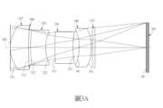
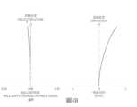
請參照圖1A及圖1B,其中圖1A繪示依照本發明第一實施例之成像透鏡組的示意圖,圖1B由左至右依序為第一實施例的成像透鏡組的像面彎曲及歪曲收差曲線圖。由圖1A可知,成像透鏡組係包含有一光圈100和一光學組,且該成像透鏡組搭配一影像感測器182使用,該光學組沿光軸190由物側至像側依序包含第一透鏡110、第二透鏡120、第三透鏡130、第四透鏡140、紅外線濾除濾光元件170、以及成像面181。其中該成像透鏡組中具屈折力的透鏡為四片。該光圈100設置在第一透鏡110與第二透鏡120之間。該影像感測器182設置於該成像面181上。Please refer to FIG. 1A and FIG. 1B , wherein FIG. 1A is a schematic diagram of an imaging lens assembly according to the first embodiment of the present invention, and FIG. 1B is a diagram of the image plane bending and distortion aberration curves of the imaging lens assembly of the first embodiment from left to right. As can be seen from FIG. 1A , the imaging lens assembly includes an
該第一透鏡110具有正屈折力,且為塑膠材質,其物側表面111近光軸190處為凸面,其像側表面112近光軸190處為凹面,且該物側表面111及像側表面112皆為非球面。The
該第二透鏡120具有負屈折力,且為塑膠材質,其物側表面121近光軸190處為凸面,其像側表面122近光軸190處為凹面,且該物側表面121及像側表面122皆為非球面。The
該第三透鏡130具有負屈折力,且為塑膠材質,其物側表面131近光軸190處為凸面,其像側表面132近光軸190處為凹面,且該物側表面131及像側表面132皆為非球面。The
該第四透鏡140具有正屈折力,且為塑膠材質,其物側表面141近光軸190處為凹面,其像側表面142近光軸190處為凸面,且該物側表面141及像側表面142皆為非球面。The
該紅外線濾除濾光元件170為玻璃材質,其設置於該第四透鏡140及該成像面181間且不影響該成像透鏡組的焦距。可以理解,該紅外線濾除濾光元件170也可形成於透鏡表面,該紅外線濾除濾光元件170也可以由其他材質製成。The
上述各透鏡的非球面的曲線方程式表示如下:The curve equations of the aspheric surfaces of the above lenses are expressed as follows:
其中z為沿光軸190方向在高度為h的位置以表面頂點作參考的位置值;c是透鏡表面靠近光軸190的曲率,並為曲率半徑(R)的倒數(c=1/R),R為透鏡表面靠近光軸190的曲率半徑,h是透鏡表面距離光軸190的垂直距離,k為圓錐係數(conic constant),而A、B、C、D、E、F、G……為高階非球面係數。Where z is the position value at a height of h along the
第一實施例的成像透鏡組中,成像透鏡組的焦距為f,成像透鏡組的光圈值(f-number)為Fno,成像透鏡組中最大視場角為FOV,該成像透鏡組的入射瞳孔徑為EPD,其數值如下:f=11.78(公釐);Fno= 3.47;FOV= 19.5(度) ;以及EPD=3.39。並滿足下列條件:f/FOV =0.60。In the imaging lens set of the first embodiment, the focal length of the imaging lens set is f, the aperture value (f-number) of the imaging lens set is Fno, the maximum field of view angle of the imaging lens set is FOV, and the entrance pupil diameter of the imaging lens set is EPD, which has the following values: f=11.78 (mm); Fno= 3.47; FOV= 19.5 (degrees); and EPD=3.39. And the following conditions are met: f/FOV = 0.60.
第一實施例的成像透鏡組中,該第一透鏡110的焦距為f1,該第二透鏡120的焦距為f2,並滿足下列條件:f1/f2=-0.62。In the imaging lens set of the first embodiment, the focal length of the
第一實施例的成像透鏡組中,該第三透鏡130的焦距為f3,該第四透鏡140的焦距為f4,並滿足下列條件: f3/f4=-0.14。In the imaging lens set of the first embodiment, the focal length of the
第一實施例的成像透鏡組中,該第一透鏡110的像側表面112的曲率半徑R2,該第四透鏡140的物側表面141的曲率半徑R7,並滿足下列條件:R2/R7=-6.01。In the imaging lens set of the first embodiment, the
第一實施例的成像透鏡組中,該第三透鏡130的物側表面131的曲率半徑R5,該第三透鏡130的像側表面132的曲率半徑R6,並滿足下列條件:R5/R6=1.73。In the imaging lens set of the first embodiment, the object-
第一實施例的成像透鏡組中,該第四透鏡140的物側表面141的曲率半徑R7,該第四透鏡140的像側表面142的曲率半徑R8,並滿足下列條件:R7/R8=0.92。In the imaging lens set of the first embodiment, the
第一實施例的成像透鏡組中,該第一透鏡110於光軸190上的厚度為CT1,該第二透鏡120於光軸190上的厚度為CT2,並滿足下列條件:CT1/CT2=1.73。In the imaging lens set of the first embodiment, the thickness of the
第一實施例的成像透鏡組中,該第三透鏡130於光軸190上的厚度為CT3,該第四透鏡140於光軸190上的厚度為CT4,並滿足下列條件:CT3/CT4=1.50。In the imaging lens set of the first embodiment, the thickness of the
第一實施例的成像透鏡組中,該成像透鏡組的整體焦距為f,該第四透鏡140的像側表面142至該成像面181於光軸190上的距離為BFL,並滿足下列條件:f/BFL=2.22。In the imaging lens set of the first embodiment, the overall focal length of the imaging lens set is f, the distance from the
第一實施例的成像透鏡組中,該第一透鏡110的物側表面111至第四透鏡140的像側表面142於光軸190上的距離為TD,該第四透鏡140的像側表面142至該成像面181於光軸190上的距離為BFL,並滿足下列條件:TD/BFL=1.11。In the imaging lens set of the first embodiment, the distance from the
第一實施例的成像透鏡組中,該光圈100至第四透鏡140的像側表面142於光軸190上的距離為SD,該第四透鏡140的像側表面142至該成像面181於光軸190上的距離為BFL,並滿足下列條件:SD/BFL=0.80。In the imaging lens set of the first embodiment, the distance from the
第一實施例的成像透鏡組中,該第一透鏡110的焦距為f1,該第一透鏡110的物側表面111至第四透鏡140的像側表面142於光軸190上的距離為TD,並滿足下列條件:f1/TD=0.98。In the imaging lens set of the first embodiment, the focal length of the
第一實施例的成像透鏡組中,該第一透鏡110與第二透鏡120的合成焦距為f12,該第三透鏡130與第四透鏡140的合成焦距為f34,並滿足下列條件:f12/f34=-0.26。In the imaging lens set of the first embodiment, the combined focal length of the
第一實施例的成像透鏡組中,該第一透鏡110的物側表面111的最大有效半徑為DT11,第四透鏡140的像側表面142的最大有效半徑為DT42,並滿足下列條件:DT11/DT42=1.40。In the imaging lens set of the first embodiment, the maximum effective radius of the
第一實施例的成像透鏡組中,該成像透鏡組的入射瞳孔徑為EPD,該成像透鏡組在成像面可擷取的成像高度的一半為IMH,並滿足下列條件:EPD/IMH=1.66。In the imaging lens set of the first embodiment, the entrance pupil diameter of the imaging lens set is EPD, half of the imaging height that can be captured by the imaging lens set on the imaging surface is IMH, and the following condition is met: EPD/IMH=1.66.
再配合參照下列表1及表2。Please refer to Table 1 and Table 2 below.
表1為圖1A第一實施例詳細的結構數據,其中曲率半徑、厚度、間隙及焦距的單位為mm,且表面0-12依序表示由物側至像側的表面,其中表面0為被攝物與該第一透鏡110之間在光軸190上的間隙;表面3為該光圈100與該第一透鏡110的物側表面111之間在光軸190上的間隙;表面1、4、6、8、10分別為該第一透鏡110、該第二透鏡120、該第三透鏡130、該第四透鏡140、該紅外線濾除濾光元件170在該光軸190上的厚度;表面2、5、7、9、11分別為該第一透鏡110與該光圈100之間在該光軸190上的間隙、該第二透鏡120與該第三透鏡30之間在該光軸190上的間隙、該第三透鏡130與該第四透鏡140之間在該光軸190上的間隙、該第四透鏡140與該紅外線濾除濾光元件170之間在該光軸190上的間隙、該紅外線濾除濾光元件170與成像面181之間在該光軸190上的間隙。Table 1 is the detailed structural data of the first embodiment of FIG. 1A, wherein the units of the radius of curvature, thickness, gap and focal length are mm, and surfaces 0-12 represent the surfaces from the object side to the image side in sequence, wherein
表2為第一實施例中的非球面數據,其中,k表非球面曲線方程式中的錐面係數,A、B、C、D、E、F、G……為高階非球面係數。此外,以下各實施例表格乃對應各實施例的示意圖與像面彎曲曲線圖,表格中數據的定義皆與第一實施例的表1、及表2的定義相同,在此不加贅述。Table 2 is the aspheric surface data in the first embodiment, wherein k represents the cone coefficient in the aspheric surface curve equation, and A, B, C, D, E, F, G, ... are high-order aspheric surface coefficients. In addition, the following tables of the embodiments correspond to the schematic diagrams and image plane bending curve diagrams of the embodiments, and the definitions of the data in the tables are the same as those in Table 1 and Table 2 of the first embodiment, and are not elaborated here.
<第二實施例><Second embodiment>
請參照圖2A及圖2B,其中圖2A繪示依照本發明第二實施例之成像透鏡組的示意圖,圖2B由左至右依序為第二實施例的成像透鏡組的像面彎曲及歪曲收差曲線圖。由圖2A可知,成像透鏡組係包含有一光圈200和一光學組,且該成像透鏡組搭配一影像感測器282使用,該光學組沿光軸290由物側至像側依序包含第一透鏡210、第二透鏡220、第三透鏡230、第四透鏡240、紅外線濾除濾光元件270、以及成像面281。其中該成像透鏡組中具屈折力的透鏡為四片。該光圈200設置在第一透鏡210與第二透鏡220之間。該影像感測器282設置於該成像面281上。Please refer to FIG. 2A and FIG. 2B, wherein FIG. 2A is a schematic diagram of an imaging lens assembly according to the second embodiment of the present invention, and FIG. 2B is a graph of image plane bending and distortion aberration curves of the imaging lens assembly of the second embodiment from left to right. As can be seen from FIG. 2A, the imaging lens assembly includes an
該第一透鏡210具有正屈折力,且為塑膠材質,其物側表面211近光軸290處為凸面,其像側表面212近光軸290處為凹面,且該物側表面211及像側表面212皆為非球面。The
該第二透鏡220具有負屈折力,且為塑膠材質,其物側表面221近光軸290處為凸面,其像側表面222近光軸290處為凹面,且該物側表面221及像側表面222皆為非球面。The
該第三透鏡230具有負屈折力,且為塑膠材質,其物側表面231近光軸290處為凹面,其像側表面232近光軸290處為凹面,且該物側表面231及像側表面232皆為非球面。The
該第四透鏡240具有正屈折力,且為塑膠材質,其物側表面241近光軸290處為凸面,其像側表面242近光軸290處為凸面,且該物側表面241及像側表面242皆為非球面。The
該紅外線濾除濾光元件270為玻璃材質,其設置於該第四透鏡240及該成像面281間且不影響該成像透鏡組的焦距。可以理解,該紅外線濾除濾光元件270也可形成於透鏡表面,該紅外線濾除濾光元件270也可以由其他材質製成。The
再配合參照下列表3、以及表4。Please refer to Table 3 and Table 4 below.
第二實施例中,非球面的曲線方程式表示如第一實施例的形式。此外,下表參數的定義皆與第一實施例相同,在此不加以贅述。In the second embodiment, the curve equation of the aspheric surface is expressed in the same form as in the first embodiment. In addition, the definitions of the parameters in the following table are the same as those in the first embodiment and are not further described here.
配合表3、以及表4可推算出下列數據:The following data can be calculated by combining Table 3 and Table 4:
<第三實施例><Third Embodiment>
請參照圖3A及圖3B,其中圖3A繪示依照本發明第三實施例之成像透鏡組的示意圖,圖3B由左至右依序為第三實施例的成像透鏡組的像面彎曲及歪曲收差曲線圖。由圖3A可知,成像透鏡組係包含有一光圈300和一光學組,且該成像透鏡組搭配一影像感測器382使用,該光學組沿光軸390由物側至像側依序包含第一透鏡310、第二透鏡320、第三透鏡330、第四透鏡340、紅外線濾除濾光元件370、以及成像面381。其中該成像透鏡組中具屈折力的透鏡為四片。該光圈300設置在第一透鏡310與第二透鏡320之間。該影像感測器382設置於該成像面381上。Please refer to FIG. 3A and FIG. 3B , where FIG. 3A is a schematic diagram of an imaging lens assembly according to the third embodiment of the present invention, and FIG. 3B is a graph of the image plane bending and distortion aberration curves of the imaging lens assembly of the third embodiment from left to right. As can be seen from FIG. 3A , the imaging lens assembly includes an
該第一透鏡310具有正屈折力,且為塑膠材質,其物側表面311近光軸390處為凸面,其像側表面312近光軸390處為凹面,且該物側表面311及像側表面312皆為非球面。The
該第二透鏡320具有負屈折力,且為塑膠材質,其物側表面321近光軸390處為凸面,其像側表面322近光軸390處為凹面,且該物側表面321及像側表面322皆為非球面。The
該第三透鏡330具有負屈折力,且為塑膠材質,其物側表面331近光軸390處為凸面,其像側表面332近光軸390處為凹面,且該物側表面331及像側表面332皆為非球面。The
該第四透鏡340具有正屈折力,且為塑膠材質,其物側表面341近光軸390處為凹面,其像側表面342近光軸390處為凸面,且該物側表面341及像側表面342皆為非球面。The
該紅外線濾除濾光元件370為玻璃材質,其設置於該第四透鏡340及該成像面381間且不影響該成像透鏡組的焦距。可以理解,該紅外線濾除濾光元件370也可形成於透鏡表面,該紅外線濾除濾光元件370也可以由其他材質製成。The
再配合參照下列表5、以及表6。Please refer to Table 5 and Table 6 below.
第三實施例中,非球面的曲線方程式表示如第一實施例的形式。此外,下表參數的定義皆與第一實施例相同,在此不加以贅述。In the third embodiment, the curve equation of the aspheric surface is expressed in the same form as in the first embodiment. In addition, the definitions of the parameters in the following table are the same as those in the first embodiment and are not elaborated here.
配合表5、以及表6可推算出下列數據:The following data can be calculated by combining Table 5 and Table 6:
<第四實施例><Fourth embodiment>
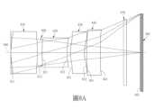
請參照圖4A及圖4B,其中圖4A繪示依照本發明第四實施例之成像透鏡組的示意圖,圖4B由左至右依序為第四實施例的成像透鏡組的像面彎曲及歪曲收差曲線圖。由圖4A可知,成像透鏡組係包含有一光圈400和一光學組,且該成像透鏡組搭配一影像感測器482使用,該光學組沿光軸490由物側至像側依序包含第一透鏡410、第二透鏡420、第三透鏡430、第四透鏡440、紅外線濾除濾光元件470、以及成像面481。其中該成像透鏡組中具屈折力的透鏡為四片。該光圈400設置在第一透鏡410與第二透鏡420之間。該影像感測器482設置於該成像面481上。Please refer to FIG. 4A and FIG. 4B , wherein FIG. 4A is a schematic diagram of an imaging lens assembly according to the fourth embodiment of the present invention, and FIG. 4B is a diagram of the image plane bending and distortion aberration curves of the imaging lens assembly of the fourth embodiment from left to right. As can be seen from FIG. 4A , the imaging lens assembly includes an
該第一透鏡410具有正屈折力,且為塑膠材質,其物側表面411近光軸490處為凸面,其像側表面412近光軸490處為凸面,且該物側表面411及像側表面412皆為非球面。The
該第二透鏡420具有負屈折力,且為塑膠材質,其物側表面421近光軸490處為凸面,其像側表面422近光軸490處為凹面,且該物側表面421及像側表面422皆為非球面。The
該第三透鏡430具有負屈折力,且為塑膠材質,其物側表面431近光軸490處為凸面,其像側表面432近光軸490處為凹面,且該物側表面431及像側表面432皆為非球面。The
該第四透鏡440具有正屈折力,且為塑膠材質,其物側表面441近光軸490處為凸面,其像側表面442近光軸490處為凸面,且該物側表面441及像側表面442皆為非球面。The
該紅外線濾除濾光元件470為玻璃材質,其設置於該第四透鏡440及該成像面481間且不影響該成像透鏡組的焦距。可以理解,該紅外線濾除濾光元件470也可形成於透鏡表面,該紅外線濾除濾光元件470也可以由其他材質製成。The
再配合參照下列表7、以及表8。Please refer to Table 7 and Table 8 below.
第四實施例中,非球面的曲線方程式表示如第一實施例的形式。此外,下表參數的定義皆與第一實施例相同,在此不加以贅述。In the fourth embodiment, the curve equation of the aspheric surface is expressed in the same form as in the first embodiment. In addition, the definitions of the parameters in the following table are the same as those in the first embodiment and are not elaborated here.
配合表7、以及表8可推算出下列數據:The following data can be calculated by combining Table 7 and Table 8:
<第五實施例><Fifth Embodiment>
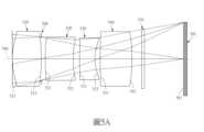
請參照圖5A及圖5B,其中圖5A繪示依照本發明第五實施例之成像透鏡組的示意圖,圖5B由左至右依序為第五實施例的成像透鏡組的像面彎曲及歪曲收差曲線圖。由圖5A可知,成像透鏡組係包含有一光圈500和一光學組,且該成像透鏡組搭配一影像感測器582使用,該光學組沿光軸590由物側至像側依序包含第一透鏡510、第二透鏡520、第三透鏡530、第四透鏡540、紅外線濾除濾光元件570、以及成像面581。其中該成像透鏡組中具屈折力的透鏡為四片。該光圈500設置在第一透鏡510與第二透鏡520之間。該影像感測器582設置於該成像面581上。Please refer to FIG. 5A and FIG. 5B , where FIG. 5A is a schematic diagram of an imaging lens assembly according to the fifth embodiment of the present invention, and FIG. 5B is a graph of image plane bending and distortion aberration curves of the imaging lens assembly of the fifth embodiment from left to right. As can be seen from FIG. 5A , the imaging lens assembly includes an
該第一透鏡510具有正屈折力,且為塑膠材質,其物側表面511近光軸590處為凸面,其像側表面512近光軸590處為凸面,且該物側表面511及像側表面512皆為非球面。The
該第二透鏡520具有負屈折力,且為塑膠材質,其物側表面521近光軸590處為凸面,其像側表面522近光軸590處為凹面,且該物側表面521及像側表面522皆為非球面。The
該第三透鏡530具有負屈折力,且為塑膠材質,其物側表面531近光軸590處為凸面,其像側表面532近光軸590處為凹面,且該物側表面531及像側表面532皆為非球面。The
該第四透鏡540具有正屈折力,且為塑膠材質,其物側表面541近光軸590處為凸面,其像側表面542近光軸590處為凸面,且該物側表面541及像側表面542皆為非球面。The
該紅外線濾除濾光元件570為玻璃材質,其設置於該第四透鏡540及該成像面581間且不影響該成像透鏡組的焦距。可以理解,該紅外線濾除濾光元件570也可形成於透鏡表面,該紅外線濾除濾光元件570也可以由其他材質製成。The
再配合參照下列表9、以及表10。Please refer to Table 9 and Table 10 below.
第五實施例中,非球面的曲線方程式表示如第一實施例的形式。此外,下表參數的定義皆與第一實施例相同,在此不加以贅述。In the fifth embodiment, the curve equation of the aspheric surface is expressed in the same form as in the first embodiment. In addition, the definitions of the parameters in the following table are the same as those in the first embodiment and are not elaborated here.
配合表9、以及表10可推算出下列數據:The following data can be calculated by combining Table 9 and Table 10:
<第六實施例><Sixth embodiment>
請參照圖6A及圖6B,其中圖6A繪示依照本發明第六實施例之成像透鏡組的示意圖,圖6B由左至右依序為第六實施例的成像透鏡組的像面彎曲及歪曲收差曲線圖。由圖6A可知,成像透鏡組係包含有一光圈600和一光學組,且該成像透鏡組搭配一影像感測器682使用,該光學組沿光軸690由物側至像側依序包含第一透鏡610、第二透鏡620、第三透鏡630、第四透鏡640、紅外線濾除濾光元件670、以及成像面681。其中該成像透鏡組中具屈折力的透鏡為四片。該光圈600設置在第一透鏡610與第二透鏡620之間。該影像感測器682設置於該成像面681上。Please refer to FIG. 6A and FIG. 6B , where FIG. 6A is a schematic diagram of an imaging lens assembly according to the sixth embodiment of the present invention, and FIG. 6B is a graph showing the image plane bending and distortion aberration curves of the imaging lens assembly of the sixth embodiment from left to right. As can be seen from FIG. 6A , the imaging lens assembly includes an
該第一透鏡610具有正屈折力,且為塑膠材質,其物側表面611近光軸690處為凸面,其像側表面612近光軸690處為凸面,且該物側表面611及像側表面612皆為非球面。The
該第二透鏡620具有負屈折力,且為塑膠材質,其物側表面621近光軸690處為凸面,其像側表面622近光軸690處為凹面,且該物側表面621及像側表面622皆為非球面。The
該第三透鏡630具有負屈折力,且為塑膠材質,其物側表面631近光軸690處為凸面,其像側表面632近光軸690處為凹面,且該物側表面631及像側表面632皆為非球面。The
該第四透鏡640具有正屈折力,且為塑膠材質,其物側表面641近光軸690處為凸面,其像側表面642近光軸690處為凸面,且該物側表面641及像側表面642皆為非球面。The
該紅外線濾除濾光元件670為玻璃材質,其設置於該第四透鏡640及該成像面681間且不影響該成像透鏡組的焦距。可以理解,該紅外線濾除濾光元件670也可形成於透鏡表面,該紅外線濾除濾光元件670也可以由其他材質製成。The
再配合參照下列表11、以及表12。Please refer to Table 11 and Table 12 below.
第六實施例中,非球面的曲線方程式表示如第一實施例的形式。此外,下表參數的定義皆與第一實施例相同,在此不加以贅述。In the sixth embodiment, the curve equation of the aspheric surface is expressed in the same form as in the first embodiment. In addition, the definitions of the parameters in the following table are the same as those in the first embodiment and are not elaborated here.
配合表11、以及表12可推算出下列數據:The following data can be calculated by combining Table 11 and Table 12:
<第七實施例><Seventh Embodiment>
請參照圖7A及圖7B,其中圖7A繪示依照本發明第七實施例之成像透鏡組的示意圖,圖7B由左至右依序為第七實施例的成像透鏡組的像面彎曲及歪曲收差曲線圖。由圖7A可知,成像透鏡組係包含有一光圈700和一光學組,且該成像透鏡組搭配一影像感測器782使用,該光學組沿光軸790由物側至像側依序包含第一透鏡710、第二透鏡720、第三透鏡730、第四透鏡740、紅外線濾除濾光元件770、以及成像面781。其中該成像透鏡組中具屈折力的透鏡為四片。該光圈700設置在第一透鏡710與第二透鏡720之間。該影像感測器782設置於該成像面781上。Please refer to FIG. 7A and FIG. 7B , where FIG. 7A is a schematic diagram of an imaging lens assembly according to the seventh embodiment of the present invention, and FIG. 7B is a graph showing the image plane bending and distortion aberration curves of the imaging lens assembly of the seventh embodiment from left to right. As can be seen from FIG. 7A , the imaging lens assembly includes an
該第一透鏡710具有正屈折力,且為塑膠材質,其物側表面711近光軸790處為凸面,其像側表面712近光軸790處為凹面,且該物側表面711及像側表面712皆為非球面。The
該第二透鏡720具有負屈折力,且為塑膠材質,其物側表面721近光軸790處為凸面,其像側表面722近光軸790處為凹面,且該物側表面721及像側表面722皆為非球面。The
該第三透鏡730具有負屈折力,且為塑膠材質,其物側表面731近光軸790處為凸面,其像側表面732近光軸790處為凹面,且該物側表面731及像側表面732皆為非球面。The
該第四透鏡740具有正屈折力,且為塑膠材質,其物側表面741近光軸790處為凹面,其像側表面742近光軸790處為凸面,且該物側表面741及像側表面742皆為非球面。The
該紅外線濾除濾光元件770為玻璃材質,其設置於該第四透鏡740及該成像面781間且不影響該成像透鏡組的焦距。可以理解,該紅外線濾除濾光元件770也可形成於透鏡表面,該紅外線濾除濾光元件770也可以由其他材質製成。The
再配合參照下列表13、以及表14。Please refer to Table 13 and Table 14 below.
第七實施例中,非球面的曲線方程式表示如第一實施例的形式。此外,下表參數的定義皆與第一實施例相同,在此不加以贅述。In the seventh embodiment, the curve equation of the aspheric surface is expressed in the same form as in the first embodiment. In addition, the definitions of the parameters in the following table are the same as those in the first embodiment and are not elaborated here.
配合表13、以及表14可推算出下列數據:The following data can be calculated by combining Table 13 and Table 14:
<第八實施例><Eighth Embodiment>
請參照圖8A及圖8B,其中圖8A繪示依照本發明第八實施例之成像透鏡組的示意圖,圖8B由左至右依序為第八實施例的成像透鏡組的像面彎曲及歪曲收差曲線圖。由圖8A可知,成像透鏡組係包含有一光圈800和一光學組,且該成像透鏡組搭配一影像感測器882使用,該光學組沿光軸890由物側至像側依序包含第一透鏡810、第二透鏡820、第三透鏡830、第四透鏡840、紅外線濾除濾光元件870、以及成像面881。其中該成像透鏡組中具屈折力的透鏡為四片。該光圈800設置在第一透鏡810與第二透鏡820之間。該影像感測器882設置於該成像面881上。Please refer to FIG. 8A and FIG. 8B, wherein FIG. 8A is a schematic diagram of an imaging lens assembly according to the eighth embodiment of the present invention, and FIG. 8B is a graph showing the image plane bending and distortion aberration curves of the imaging lens assembly of the eighth embodiment from left to right. As can be seen from FIG. 8A, the imaging lens assembly includes an
該第一透鏡810具有正屈折力,且為塑膠材質,其物側表面811近光軸890處為凸面,其像側表面812近光軸890處為凸面,且該物側表面811及像側表面812皆為非球面。The
該第二透鏡820具有負屈折力,且為塑膠材質,其物側表面821近光軸890處為凸面,其像側表面822近光軸890處為凹面,且該物側表面821及像側表面822皆為非球面。The
該第三透鏡830具有負屈折力,且為塑膠材質,其物側表面831近光軸890處為凸面,其像側表面832近光軸890處為凹面,且該物側表面831及像側表面832皆為非球面。The
該第四透鏡840具有正屈折力,且為塑膠材質,其物側表面841近光軸890處為凸面,其像側表面842近光軸890處為凸面,且該物側表面841及像側表面842皆為非球面。The
該紅外線濾除濾光元件870為玻璃材質,其設置於該第四透鏡840及該成像面881間且不影響該成像透鏡組的焦距。可以理解,該紅外線濾除濾光元件870也可形成於透鏡表面,該紅外線濾除濾光元件870也可以由其他材質製成。The
再配合參照下列表15、以及表16。Please refer to Table 15 and Table 16 below.
第八實施例中,非球面的曲線方程式表示如第一實施例的形式。此外,下表參數的定義皆與第一實施例相同,在此不加以贅述。In the eighth embodiment, the curve equation of the aspheric surface is expressed in the same form as in the first embodiment. In addition, the definitions of the parameters in the following table are the same as those in the first embodiment and are not elaborated here.
配合表15、以及表16可推算出下列數據:The following data can be calculated by combining Table 15 and Table 16:
<第九實施例><Ninth Embodiment>
請參照圖9,繪示依照本發明第九實施例之攝像模組。在本實施例中,該攝像模組應用於筆記型電腦,但不以此為限。該攝像模組10並包含成像透鏡組11、鏡筒12及影像感測器182。該成像透鏡組11為上述第一實施例的成像透鏡組,但不以此為限,為上述其他實施例的成像透鏡組亦可,另外,圖9所繪製的成像透鏡組的各透鏡為顯示出未取光的周邊部分,而與第一實施例的各透鏡略顯不同。該鏡筒12供該成像透鏡組11容置。該影像感測器182,設置於該成像透鏡組11的成像面181,且為一感光度佳及低雜訊的電子感光元件(如CMOS、CCD),以真實呈現成像透鏡組的成像品質。Please refer to FIG. 9, which shows a camera module according to the ninth embodiment of the present invention. In this embodiment, the camera module is applied to a laptop computer, but not limited thereto. The camera module 10 also includes an imaging lens group 11, a barrel 12, and an
本發明提供的成像透鏡組,透鏡的材質可為塑膠或玻璃,當透鏡材質為塑膠,可以有效降低生產成本,另當透鏡的材質為玻璃,則可以增加成像透鏡組屈折力配置的自由度。此外,成像透鏡組中透鏡的物側表面及像側表面可為非球面,非球面可以容易製作成球面以外的形狀,獲得較多的控制變數,用以消減像差,進而縮減透鏡使用的數目,因此可以有效降低本發明成像透鏡組的總長度。The imaging lens set provided by the present invention can be made of plastic or glass. When the lens is made of plastic, the production cost can be effectively reduced. When the lens is made of glass, the freedom of refractive power configuration of the imaging lens set can be increased. In addition, the object side surface and the image side surface of the lens in the imaging lens set can be aspherical. The aspherical surface can be easily made into a shape other than a spherical surface, and more control variables can be obtained to eliminate aberrations, thereby reducing the number of lenses used, thereby effectively reducing the total length of the imaging lens set of the present invention.
本發明提供的成像透鏡組中,就以具有屈折力的透鏡而言,若透鏡表面係為凸面且未界定該凸面位置時,則表示該透鏡表面於近光軸處為凸面;若透鏡表面係為凹面且未界定該凹面位置時,則表示該透鏡表面於近光軸處為凹面。In the imaging lens assembly provided by the present invention, with respect to a lens having refractive power, if the lens surface is convex and the position of the convex surface is not defined, it means that the lens surface is convex near the optical axis; if the lens surface is concave and the position of the concave surface is not defined, it means that the lens surface is concave near the optical axis.
本發明提供的成像透鏡組更可視需求應用於移動對焦的光學系統中,並兼具優良像差修正與良好成像品質的特色,可多方面應用於3D(三維)影像擷取、數位相機、行動裝置、數位平板或車用攝影等電子影像系統中。The imaging lens assembly provided by the present invention can be applied to a mobile focusing optical system according to the needs, and has the characteristics of excellent aberration correction and good imaging quality. It can be widely applied to electronic imaging systems such as 3D (three-dimensional) image capture, digital cameras, mobile devices, digital tablets or car photography.
綜上所述,上述各實施例及圖式僅為本發明的較佳實施例而已,當不能以之限定本發明實施之範圍,即大凡依本發明申請專利範圍所作的均等變化與修飾,皆應屬本發明專利涵蓋的範圍內。In summary, the above embodiments and drawings are only preferred embodiments of the present invention and should not be used to limit the scope of implementation of the present invention. In other words, all equivalent changes and modifications made according to the scope of the patent application of the present invention should fall within the scope of the patent of the present invention.
100、200、300、400、500、600、700、800:光圈 110、210、310、410、510、610、710、810:第一透鏡 111、211、311、411、511、611、711、811:物側表面 112、212、312、412、512、612、712、812:像側表面 120、220、320、420、520、620、720、820:第二透鏡 121、221、321、421、521、621、721、821:物側表面 122、222、322、422、522、622、722、822:像側表面 130、230、330、430、530、630、730、830:第三透鏡 131、231、331、431、531、631、731、831:物側表面 132、232、332、432、532、632、732、832:像側表面 140、240、340、440、540、640、740、840:第四透鏡 141、241、341、441、541、641、741、841:物側表面 142、242、342、442、542、642、742、842:像側表面 150、250、350、450、550、650、750、850:第五透鏡 151、251、351、451、551、651、751、851:物側表面 152、252、352、452、552、652、752、852:像側表面 160、260、360、460、560、660、760;860:第六透鏡 161、261、361、461、561、661、761、861:物側表面 162、262、362、462、562、662、762、862:像側表面 170、270、370、470、570、670、760、860:紅外線濾除濾光元件 181、281、381、481、581、681、781、881:成像面 182、282、382、482、582、682、782、882:影像感測器 190、290、390、490、590、690、790、890:光軸 10:攝像模組 11:成像透鏡組 12:鏡筒 f:成像透鏡組的整體焦距 Fno:光圈值 FOV:成像透鏡組的最大視角 f1:第一透鏡的焦距 f2:第二透鏡的焦距 f3:第三透鏡的焦距 f4:第四透鏡的焦距 f12:第一透鏡與第二透鏡的合成焦距 f34:第三透鏡與第四透鏡的合成焦距 R2:第一透鏡的像側表面的曲率半徑 R5:第三透鏡的物側表面的曲率半徑 R6:第三透鏡的像側表面的曲率半徑 R7:第四透鏡的物側表面的曲率半徑 R8:第四透鏡的像側表面的曲率半徑 CT1:第一透鏡於光軸上的厚度 CT2:第二透鏡於光軸上的厚度 CT3:第三透鏡於光軸上的厚度 CT4:第四透鏡於光軸上的厚度 BFL:第四透鏡的像側表面至成像面於光軸上的距離 TD:第一透鏡的物側表面至第四透鏡的像側表面於光軸上的距離 SD:光圈至第四透鏡的像側表面於光軸上的距離 DT11:第一透鏡的物側表面的最大有效半徑 DT42:第四透鏡的像側表面的最大有效半徑 EPD:成像透鏡組的入射瞳孔徑 IMH:成像透鏡組在成像面可擷取的成像高度的一半100, 200, 300, 400, 500, 600, 700, 800: aperture110, 210, 310, 410, 510, 610, 710, 810: first lens111, 211, 311, 411, 511, 611, 711, 811: object side surface112, 212, 312, 412, 512, 612, 712, 812: image side surface120, 220, 320, 420, 520, 620, 720, 820: second lens121, 221, 321, 421, 521, 621, 721, 821: object side surface122, 222, 322, 422, 522, 622, 722, 822: Image side surface130, 230, 330, 430, 530, 630, 730, 830: Third lens131, 231, 331, 431, 531, 631, 731, 831: Object side surface132, 232, 332, 432, 532, 632, 732, 832: Image side surface140, 240, 340, 440, 540, 640, 740, 840: Fourth lens141, 241, 341, 441, 541, 641, 741, 841: Object side surface142, 242, 342, 442, 542, 642, 742, 842: Image side surface150, 250, 350, 450, 550, 650, 750, 850: Fifth lens151, 251, 351, 451, 551, 651, 751, 851: Object side surface152, 252, 352, 452, 552, 652, 752, 852: Image side surface160, 260, 360, 460, 560, 660, 760; 860: Sixth lens161, 261, 361, 461, 561, 661, 761, 861: Object side surface162, 262, 362, 462, 562, 662, 762, 862: Image side surface170, 270, 370, 470, 570, 670, 760, 860: Infrared filter element181, 281, 381, 481, 581, 681, 781, 881: Imaging surface182, 282, 382, 482, 582, 682, 782, 882: Image sensor190, 290, 390, 490, 590, 690, 790, 890: Optical axis10: Imaging module11: Imaging lens group12: Lens barrelf: Overall focal length of the imaging lens groupFno: aperture valueFOV: maximum viewing angle of the imaging lens groupf1: focal length of the first lensf2: focal length of the second lensf3: focal length of the third lensf4: focal length of the fourth lensf12: composite focal length of the first lens and the second lensf34: composite focal length of the third lens and the fourth lensR2: radius of curvature of the image side surface of the first lensR5: radius of curvature of the object side surface of the third lensR6: radius of curvature of the image side surface of the third lensR7: radius of curvature of the object side surface of the fourth lensR8: radius of curvature of the image side surface of the fourth lensCT1: thickness of the first lens on the optical axisCT2: thickness of the second lens on the optical axisCT3: thickness of the third lens on the optical axisCT4: thickness of the fourth lens on the optical axisBFL: distance from the image side surface of the fourth lens to the imaging surface on the optical axisTD: distance from the object side surface of the first lens to the image side surface of the fourth lens on the optical axisSD: distance from the aperture to the image side surface of the fourth lens on the optical axisDT11: maximum effective radius of the object side surface of the first lensDT42: maximum effective radius of the image side surface of the fourth lensEPD: entrance pupil diameter of the imaging lens groupIMH: half of the imaging height that can be captured by the imaging lens group on the imaging surface
圖1A係本發明第一實施例之成像透鏡組的示意圖。 圖1B由左至右依序為第一實施例的成像透鏡組的像面彎曲及歪曲收差曲線圖。 圖2A係本發明第二實施例之成像透鏡組的示意圖。 圖2B由左至右依序為第二實施例的成像透鏡組的像面彎曲及歪曲收差曲線圖。 圖3A係本發明第三實施例之成像透鏡組的示意圖。 圖3B由左至右依序為第三實施例的成像透鏡組的像面彎曲及歪曲收差曲線圖。 圖4A係本發明第四實施例之成像透鏡組的示意圖。 圖4B由左至右依序為第四實施例的成像透鏡組的像面彎曲及歪曲收差曲線圖。 圖5A係本發明第五實施例之成像透鏡組的示意圖。 圖5B由左至右依序為第五實施例的成像透鏡組的像面彎曲及歪曲收差曲線圖。 圖6A係本發明第六實施例之成像透鏡組的示意圖。 圖6B由左至右依序為第六實施例的成像透鏡組的像面彎曲及歪曲收差曲線圖。 圖7A係本發明第七實施例之成像透鏡組的示意圖。 圖7B由左至右依序為第七實施例的成像透鏡組的像面彎曲及歪曲收差曲線圖。 圖8A係本發明第八實施例之成像透鏡組的示意圖。 圖8B由左至右依序為第八實施例的成像透鏡組的像面彎曲及歪曲收差曲線圖。 圖9係本發明第九實施例之攝像模組的示意圖。FIG. 1A is a schematic diagram of an imaging lens assembly of the first embodiment of the present invention.FIG. 1B is a diagram of the image plane curvature and distortion aberration curves of the imaging lens assembly of the first embodiment from left to right.FIG. 2A is a schematic diagram of an imaging lens assembly of the second embodiment of the present invention.FIG. 2B is a diagram of the image plane curvature and distortion aberration curves of the imaging lens assembly of the second embodiment from left to right.FIG. 3A is a schematic diagram of an imaging lens assembly of the third embodiment of the present invention.FIG. 3B is a diagram of the image plane curvature and distortion aberration curves of the imaging lens assembly of the third embodiment from left to right.FIG. 4A is a schematic diagram of an imaging lens assembly of the fourth embodiment of the present invention.FIG. 4B is a diagram of the image plane curvature and distortion aberration curves of the imaging lens group of the fourth embodiment from left to right.FIG. 5A is a schematic diagram of the imaging lens group of the fifth embodiment of the present invention.FIG. 5B is a diagram of the image plane curvature and distortion aberration curves of the imaging lens group of the fifth embodiment from left to right.FIG. 6A is a schematic diagram of the imaging lens group of the sixth embodiment of the present invention.FIG. 6B is a diagram of the image plane curvature and distortion aberration curves of the imaging lens group of the sixth embodiment from left to right.FIG. 7A is a schematic diagram of the imaging lens group of the seventh embodiment of the present invention.FIG. 7B is a diagram of the image plane curvature and distortion aberration curves of the imaging lens group of the seventh embodiment from left to right.FIG8A is a schematic diagram of an imaging lens assembly of the eighth embodiment of the present invention.FIG8B is a diagram of the image plane bending and distortion aberration curves of the imaging lens assembly of the eighth embodiment from left to right.FIG9 is a schematic diagram of an imaging module of the ninth embodiment of the present invention.
100:光圈100: Aperture
110:第一透鏡110: First lens
111:物側表面111: Object side surface
112:像側表面112: Image side surface
120:第二透鏡120: Second lens
121:物側表面121: Object side surface
122:像側表面122: Image side surface
130:第三透鏡130: The third lens
131:物側表面131: Object side surface
132:像側表面132: Image side surface
140:第四透鏡140: The fourth lens
141:物側表面141: Object side surface
142:像側表面142: Image side surface
170:紅外線濾除濾光元件170: Infrared filter element
181:成像面181: Imaging surface
182:影像感測器182: Image sensor
190:光軸190: Light axis
BFL:第四透鏡的像側表面至成像面於光軸上的距離BFL: The distance from the image side surface of the fourth lens to the imaging plane on the optical axis
TD:第一透鏡的物側表面至第四透鏡的像側表面於光軸上的距離TD: The distance from the object side surface of the first lens to the image side surface of the fourth lens on the optical axis
SD:光圈至第四透鏡的像側表面於光軸上的距離SD: The distance from the aperture to the image side surface of the fourth lens on the optical axis
IMH:成像透鏡組在成像面可擷取的成像高度的一半IMH: Half of the image height that the imaging lens group can capture on the imaging surface
Claims (18)
Translated fromChinesePriority Applications (3)
| Application Number | Priority Date | Filing Date | Title |
|---|---|---|---|
| TW110114859ATWI861392B (en) | 2021-04-26 | 2021-04-26 | Optical lens assembly and photographing module |
| CN202110635762.9ACN115248493B (en) | 2021-04-26 | 2021-06-08 | Imaging lens group and camera module |
| US17/376,174US12044824B2 (en) | 2021-04-26 | 2021-07-15 | Optical lens assembly and photographing module |
Applications Claiming Priority (1)
| Application Number | Priority Date | Filing Date | Title |
|---|---|---|---|
| TW110114859ATWI861392B (en) | 2021-04-26 | 2021-04-26 | Optical lens assembly and photographing module |
Publications (2)
| Publication Number | Publication Date |
|---|---|
| TW202242472A TW202242472A (en) | 2022-11-01 |
| TWI861392Btrue TWI861392B (en) | 2024-11-11 |
Family
ID=83694110
Family Applications (1)
| Application Number | Title | Priority Date | Filing Date |
|---|---|---|---|
| TW110114859ATWI861392B (en) | 2021-04-26 | 2021-04-26 | Optical lens assembly and photographing module |
Country Status (3)
| Country | Link |
|---|---|
| US (1) | US12044824B2 (en) |
| CN (1) | CN115248493B (en) |
| TW (1) | TWI861392B (en) |
Citations (3)
| Publication number | Priority date | Publication date | Assignee | Title |
|---|---|---|---|---|
| TW201823791A (en)* | 2016-12-15 | 2018-07-01 | 大立光電股份有限公司 | Optical photographing lens system, image capturing apparatus and electronic device |
| US20180188480A1 (en)* | 2017-01-04 | 2018-07-05 | Ability Opto-Electronics Technology Co.Ltd. | Optical Image Capturing System |
| CN112684580A (en)* | 2020-12-29 | 2021-04-20 | 诚瑞光学(苏州)有限公司 | Image pickup optical lens |
Family Cites Families (11)
| Publication number | Priority date | Publication date | Assignee | Title |
|---|---|---|---|---|
| JP4403672B2 (en)* | 2001-06-05 | 2010-01-27 | カシオ計算機株式会社 | Shooting lens |
| JP2003215449A (en)* | 2002-01-18 | 2003-07-30 | Olympus Optical Co Ltd | Image forming lens system |
| US9223118B2 (en)* | 2013-10-31 | 2015-12-29 | Apple Inc. | Small form factor telephoto camera |
| US9864168B2 (en)* | 2014-06-23 | 2018-01-09 | Genius Electronic Optical Co., Ltd. | Near-infrared lens for cameras in mobile devices |
| TWI548894B (en)* | 2015-02-04 | 2016-09-11 | 大立光電股份有限公司 | Optical lens assembly and image capturing device |
| CN106772943B (en)* | 2015-12-29 | 2019-09-13 | 镇江磐禾商贸有限公司 | Camera optical camera lens group |
| JP6643201B2 (en)* | 2016-07-20 | 2020-02-12 | 富士フイルム株式会社 | Imaging lens and imaging device |
| CN115793192A (en)* | 2017-11-03 | 2023-03-14 | 玉晶光电(厦门)有限公司 | Optical lens group |
| CN110068909B (en)* | 2018-01-24 | 2021-08-17 | 新巨科技股份有限公司 | Four-piece infrared wavelength projection lens group |
| US10459194B2 (en)* | 2018-03-26 | 2019-10-29 | Newmax Technology Co., Ltd. | Four-piece infrared single wavelength projection lens system |
| US11614605B2 (en)* | 2020-06-14 | 2023-03-28 | Newmax Technology Co., Ltd. | Four-piece infrared single wavelength lens system |
- 2021
- 2021-04-26TWTW110114859Apatent/TWI861392B/enactive
- 2021-06-08CNCN202110635762.9Apatent/CN115248493B/enactiveActive
- 2021-07-15USUS17/376,174patent/US12044824B2/enactiveActive
Patent Citations (3)
| Publication number | Priority date | Publication date | Assignee | Title |
|---|---|---|---|---|
| TW201823791A (en)* | 2016-12-15 | 2018-07-01 | 大立光電股份有限公司 | Optical photographing lens system, image capturing apparatus and electronic device |
| US20180188480A1 (en)* | 2017-01-04 | 2018-07-05 | Ability Opto-Electronics Technology Co.Ltd. | Optical Image Capturing System |
| CN112684580A (en)* | 2020-12-29 | 2021-04-20 | 诚瑞光学(苏州)有限公司 | Image pickup optical lens |
Also Published As
| Publication number | Publication date |
|---|---|
| CN115248493A (en) | 2022-10-28 |
| US12044824B2 (en) | 2024-07-23 |
| CN115248493B (en) | 2023-09-08 |
| TW202242472A (en) | 2022-11-01 |
| US20220342183A1 (en) | 2022-10-27 |
Similar Documents
| Publication | Publication Date | Title |
|---|---|---|
| CN115016102B (en) | Optical lens group for image pickup | |
| CN107037568B (en) | Optical lens assembly for image capturing, image capturing device and electronic device | |
| TW202104964A (en) | Optical imaging lens assembly, image capturing unit and electronic device | |
| TW201715268A (en) | Image capturing lens system, image capturing apparatus and electronic device | |
| TW201837524A (en) | Photographing optical lens assembly, image capturing unit and electronic device | |
| TWI665488B (en) | Photographing optical system, image capturing unit and electronic device | |
| TWI789015B (en) | Optical lens assembly and photographing module | |
| TWI724919B (en) | Six-piece optical lens system with a wide field of view | |
| CN106980173A (en) | Wide-angle imaging lens group | |
| TW201818114A (en) | Photographing optical lens system, imaging apparatus and electronic device | |
| TW202037956A (en) | Five-piece optical lens system with a wide field of view | |
| TW202111375A (en) | Photographing optical lens system, image capturing unit and electronic device | |
| TWI769784B (en) | Optical lens system and photographing module | |
| TWI778904B (en) | Optical lens assembly and photographing module | |
| TWI786774B (en) | Optical lens assembly and photographing module | |
| CN114967044B (en) | Imaging lens group and camera module | |
| TW201809792A (en) | Optical telephoto imaging lens | |
| TWI783686B (en) | Photographing module | |
| TWI861392B (en) | Optical lens assembly and photographing module | |
| TWI819742B (en) | Optical lens assembly and photographing module | |
| TWI851089B (en) | Optical lens assembly and photographing module | |
| TWI816366B (en) | Photographing optical lens assembly, image capturing unit and electronic device | |
| TWI706183B (en) | Four-piece optical lens system | |
| TWI700513B (en) | Six-piece optical lens system | |
| TW201901221A (en) | Five-piece optical lens system |