TWI858997B - Baffle structure - Google Patents
Baffle structureDownload PDFInfo
- Publication number
- TWI858997B TWI858997BTW112144052ATW112144052ATWI858997BTW I858997 BTWI858997 BTW I858997BTW 112144052 ATW112144052 ATW 112144052ATW 112144052 ATW112144052 ATW 112144052ATW I858997 BTWI858997 BTW I858997B
- Authority
- TW
- Taiwan
- Prior art keywords
- motherboard
- baffle structure
- top plate
- plate
- fixing members
- Prior art date
Links
Images


Classifications
- G—PHYSICS
- G06—COMPUTING OR CALCULATING; COUNTING
- G06F—ELECTRIC DIGITAL DATA PROCESSING
- G06F1/00—Details not covered by groups G06F3/00 - G06F13/00 and G06F21/00
- G06F1/16—Constructional details or arrangements
- G06F1/18—Packaging or power distribution
- H—ELECTRICITY
- H01—ELECTRIC ELEMENTS
- H01R—ELECTRICALLY-CONDUCTIVE CONNECTIONS; STRUCTURAL ASSOCIATIONS OF A PLURALITY OF MUTUALLY-INSULATED ELECTRICAL CONNECTING ELEMENTS; COUPLING DEVICES; CURRENT COLLECTORS
- H01R13/00—Details of coupling devices of the kinds covered by groups H01R12/70 or H01R24/00 - H01R33/00
- H01R13/46—Bases; Cases
Landscapes
- Engineering & Computer Science (AREA)
- Theoretical Computer Science (AREA)
- Power Engineering (AREA)
- Human Computer Interaction (AREA)
- Physics & Mathematics (AREA)
- General Engineering & Computer Science (AREA)
- General Physics & Mathematics (AREA)
- Cooling Or The Like Of Electrical Apparatus (AREA)
- Connection Of Plates (AREA)
- Air-Flow Control Members (AREA)
Abstract
Description
Translated fromChinese本案是有關於一種擋板結構,且特別是有關於一種易於安裝的擋板結構。The present invention relates to a baffle structure, and in particular to a baffle structure that is easy to install.
現有應用於機箱及主機板的擋板結構因為製作廠商的不同而存在尺寸上的公差,因此擋板結構對位主機板的連接埠時不易安裝。具體而言,現有的擋板結構與主機板為相互獨立的構件,使用者自行把擋板結構安裝在機箱對應連接埠的穿孔處,然而此種擋板結構容易產生彎折且不易對位。The existing baffle structures used in computer cases and motherboards have dimensional tolerances due to differences in manufacturers, so it is difficult to install the baffle structure in alignment with the connection port of the motherboard. Specifically, the existing baffle structure and the motherboard are independent components, and the user installs the baffle structure on the perforation of the corresponding connection port of the case. However, this baffle structure is prone to bending and is difficult to align.
本案提供一種擋板結構,適於安裝於一主機板,主機板具有多個連接埠。擋板結構包括一前板、二側板、一頂板以及一定位組件。前板具有多個穿孔以及相對的一第一邊以及一第二邊,且多個穿孔適於容納多個連接埠,其中第一邊鄰近於主機板。二側板,分別配置於前板的二側,且各側板遠離前板的一端具有一空心柱。頂板配置於第二邊且二側分別連接於二側板,且頂板具有二開孔,二開孔分別對應該二空心柱。定位組件包含二固定件,二固定件分別穿過頂板以及二空心柱,進而結合於主機板。The present invention provides a baffle structure suitable for installation on a motherboard having a plurality of connection ports. The baffle structure includes a front plate, two side plates, a top plate and a positioning assembly. The front plate has a plurality of through holes and a first side and a second side opposite to each other, and the plurality of through holes are suitable for accommodating a plurality of connection ports, wherein the first side is adjacent to the motherboard. The two side plates are respectively arranged on the two sides of the front plate, and each side plate has a hollow column at one end away from the front plate. The top plate is arranged on the second side and the two sides are respectively connected to the two side plates, and the top plate has two openings, and the two openings correspond to the two hollow columns respectively. The positioning assembly includes two fixing members, and the two fixing members respectively pass through the top plate and the two hollow columns, and then are combined with the motherboard.
基於上述,本案的擋板結構,其兩側板透過定位組件而直接鎖固於主機板並容納多個連接埠。於安裝過程時,將兩側板對位於主機板的安裝處,再將前板的多個穿孔對位多個連接埠,最終將定位組件配置於頂板及兩側板以使側板的一端固定於主機板。Based on the above, the baffle structure of this case has two side panels that are directly locked to the motherboard through positioning components and accommodate multiple connection ports. During the installation process, the two side panels are aligned with the installation position of the motherboard, and then the multiple perforations of the front panel are aligned with the multiple connection ports. Finally, the positioning components are configured on the top panel and the two side panels to fix one end of the side panel to the motherboard.
進一步而言,本案的擋板結構與主機板連接為一體,相較於現有分離於主機板的擋板結構,能省去使用者自行安裝擋板結構的步驟,藉此提升組裝效率。Furthermore, the baffle structure of the present invention is connected to the motherboard as an integral whole. Compared with the existing baffle structure separated from the motherboard, the user can save the step of installing the baffle structure by himself, thereby improving assembly efficiency.
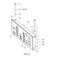
圖1A是本案一實施例的擋板結構與主機板的立體示意圖。圖1B是圖1A的擋板結構另一方向的立體示意圖。圖2A是圖1A的擋板結構結合主機板的立體示意圖。圖2B是圖2A的擋板結構結合主機板的另一角度立體示意圖。圖2C是圖2B的定位組件穿設於頂板及側板的立體示意圖。FIG. 1A is a three-dimensional schematic diagram of a baffle structure and a motherboard in an embodiment of the present invention. FIG. 1B is a three-dimensional schematic diagram of the baffle structure of FIG. 1A from another direction. FIG. 2A is a three-dimensional schematic diagram of the baffle structure of FIG. 1A combined with a motherboard. FIG. 2B is a three-dimensional schematic diagram of the baffle structure of FIG. 2A combined with a motherboard from another angle. FIG. 2C is a three-dimensional schematic diagram of the positioning assembly of FIG. 2B penetrating the top plate and the side plate.
參考圖1A、圖1B及圖2A,本案提供一種擋板結構100,適於安裝於一主機板200,主機板200具有多個連接埠210,擋板結構100用以容納且定位多個連接埠210且能部份遮擋機箱開口,進而將低外部灰塵從機箱開口進入的可能性,以減少主機板200的灰塵累積量。1A, 1B and 2A, the present invention provides a
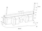
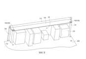
參考圖1B及圖2A,擋板結構100包括一前板110、二側板130、一頂板120以及一定位組件140。前板110具有多個穿孔TH以及相對的一第一邊S2及一第二邊S2,且多個穿孔TH是於容納多個連接埠210的端子,其中第一邊S1鄰近於主機板200且第二邊S2遠離主機板200。二側板130分別配置於前板110的對向兩側,且各側板130遠離前板110的一端具有一空心柱131。頂板120配置於前板110的第二邊S2且間隔於主機板200。頂板120的二側分別連接於二側板130,且頂板120具有二開孔OP,二開孔OP分別對應二空心柱131。Referring to FIG. 1B and FIG. 2A , the
定位組件140包含二固定件142,二固定件142分別穿過頂板120以及二空心柱131,進而結合於主機板200。補充而言,定位組件140配置於頂板120、二側板130及主機板200(見圖2C),用以將各側板130遠離頂板120的一端固定於主機板200,使擋板結構100與主機板200連接為一體。The
參考圖1B及圖2B,進一步而言,頂板120及二側板130共同構成一容納空間AS,容納空間AS部份容納多個連接埠210且頂板120及二側板130形成一U型外觀。1B and 2B , further, the
進一步而言,參考圖1B,各側板130的空心柱131,從各側板130靠近頂板120的一端延伸至各側板130遠離頂板120的另一端,且各空心柱131對位成型在頂板120的各開孔OP。其中,各空心柱為各側板的邊緣彎曲成形或是各空心柱是焊接於各側板的邊緣。Further, referring to FIG. 1B , the
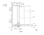
圖3是圖2C的擋板結構結合於主機板的側視示意圖。FIG. 3 is a side view schematic diagram of the baffle structure of FIG. 2C combined with a motherboard.
參考圖2B、圖2C及圖3,定位組件140具有兩螺合座141,且二固定件142為二螺絲。各螺合座141配置在主機板200遠離各側板130的一底面BS,且各螺合座141對位於各空心柱131,各固定件142依序穿設頂板120及各空心柱131並固定於各螺合座141。Referring to FIG. 2B , FIG. 2C and FIG. 3 , the
補充而言,各螺合座141的外壁面環繞形成一缺口,使得螺合座141具有缺口的一端的外徑小於另一端的外徑,則螺合座141具有缺口的一端適於自主機板200的底面BS穿設於相應孔洞,並透過焊接、卡固或黏著等方式而固定於主機板200。In addition, the outer wall surface of each
詳細而言,各螺絲142具有一頭部P1、一柱狀部P2以及一螺紋部P3。在各螺絲142依序穿設頂板120、各空心柱131及主機板200後,頭部P1貼靠於頂板120,柱狀部P2自頭部P1延伸且位於各空心柱131中,螺紋部P3成型於柱狀部P2遠離頭部P1的一端且螺紋部P3進入螺合座141並與其內螺紋相互螺合。補充而言,螺紋部P3的一外徑小於柱狀部P2的一外徑。In detail, each
參考圖1B,擋板結構100還包括兩輔助板150,分別配置在二側板130遠離頂板120的一端,各輔助板150垂直延伸於各側板130且平行於主機板200,藉由兩輔助板150面接觸主機板200的頂面TS,能提升擋板結構100安裝於主機板200的穩固性。Referring to FIG. 1B , the
參考圖1A、圖2A至圖2C及圖3,以下簡單說明擋板結構100與主機板200的安裝步驟。1A, 2A to 2C and 3, the following briefly describes the installation steps of the
參考圖3,將對應數量的螺合座141安裝於主機板200的底面BS。參考圖1A,以前板110的多個穿孔TH對應主機板200的多個連接埠210。參考圖1B、圖2A及圖3,使頂板120及二側板130所構成的容納空間AS容納多個連接埠210且兩輔助板150面接觸主機板200的頂面TS。參考圖2B及圖2C,將各螺絲142穿入頂板120的開孔OP、各空心柱131以及主機板200。參考圖3,最終各螺絲142的柱狀部P2位於相應的空心柱131中,且各螺絲142的螺紋部P3固定於相應的螺合座141。Referring to FIG3 , a corresponding number of screw-in
圖4是本案另一實施例的擋板結構結合於主機板的側視示意圖。FIG. 4 is a side view of another embodiment of the baffle structure combined with a motherboard.
參考圖4,本實施例的擋板結構100A不同於圖3所示的擋板結構100,差別在於定位組件140a具有兩螺合座141a及兩固定件142a,且二固定件142a為二螺絲,各螺合座141a配置在主機板200面向各側板130a的頂面TS,且各螺合座141a對位於各空心柱131a,各螺絲142a依序穿設頂板120a及各空心柱131a並固定於各螺合座141a。4 , the
補充而言,各螺合座141a的外壁面環繞形成一缺口,使得螺合座141a具有缺口的一端的外徑小於另一端的外徑,則螺合座141a具有缺口的一端適於自主機板200的頂面TS穿設於相應孔洞,並透過焊接、卡固或黏著等方式而固定於主機板200。In addition, the outer wall surface of each
詳細而言,各螺絲142a具有一頭部P1、一柱狀部P2以及一螺紋部P3。在各螺絲142a依序穿設頂板120a及各空心柱131a後,頭部P1貼靠於頂板120a,柱狀部P2自頭部P1延伸且位於各空心柱131a中,螺紋部P3成型於柱狀部P2遠離頭部P1的一端且螺紋部P3進入螺合座141a並與其內螺紋相互螺合。In detail, each
進一步而言,本實施例的螺合座141a為連接在主機板200的頂面TS,故各側板130a與主機板200之間形成一凹槽G,以利於容納各螺合座141a,由於各螺絲142a只需要穿設頂板120a及各空心柱131a,故能減少螺絲142a的總長度。Furthermore, the screw-in
圖5是本案另一實施例的擋板結構結合於主機板的側視剖面示意圖。FIG. 5 is a side cross-sectional diagram of another embodiment of the baffle structure combined with a motherboard.
參考圖5,本實施例的擋板結構100B不同於圖3所示的擋板結構100,差別在於定位組件140b具有一鎖固板141b及兩固定件142b,且二固定件142b為二螺絲。鎖固板141b配置在主機板200遠離各側板130b的底面BS且連接於前板110b。其中,鎖固板141b具有多個抽牙部TP以對位於各空心柱131b,各螺絲142b依序穿設頂板120b、各空心柱131b及主機板200並固定於鎖固板141b的各抽牙部TP。其中,鎖固板141b一體成型於前板110b且鎖固板141b朝向主機板200延伸。Referring to FIG. 5 , the
補充而言,鎖固板141b的抽牙部TP貼合於主機板200的底面BS且抽牙部TP連通主機板200的相應孔洞與各空心柱131b,此外,抽牙部TP能透過焊接、卡固或黏著等方式而固定於主機板200。In addition, the threading portion TP of the
詳細而言,各螺絲142b具有一頭部P1、一柱狀部P2以及一螺紋部P3。在各螺絲142b依序穿設頂板120b、各空心柱131a及主機板200後,頭部P1貼靠於頂板120b,柱狀部P2自頭部P1延伸且位於各空心柱131b中,螺紋部P3成型於柱狀部P2遠離頭部P1的一端且螺紋部P3進入鎖固板141b的各抽牙部TP以進行攻牙,最終螺紋部P3螺合於相應的抽牙部TP。In detail, each
進一步而言,抽牙部TP是通過沖壓方式於鎖固板141b上所形成且具備導引方向及孔壁,螺紋部P3進入抽牙部TP後會接觸的孔壁以形成攻牙且隨著螺紋部P3穿入長度的增加,孔壁內的牙數也隨之增加,藉此提升螺紋部P3與抽牙部TP的連接強度。Furthermore, the tapping portion TP is formed on the
綜上所述,本案的擋板結構,其二側板透過定位組件而直接鎖固於主機板並容納多個連接埠。於安裝過程時,將二側板對位於主機板的安裝處,再將前板的多個穿孔對位多個連接埠,最終將定位組件配置於頂板及二側板以使側板的一端固定於主機板。In summary, the baffle structure of this case has two side panels that are directly locked to the motherboard through positioning components and accommodate multiple connection ports. During the installation process, the two side panels are aligned with the installation position of the motherboard, and then the multiple perforations of the front panel are aligned with the multiple connection ports. Finally, the positioning components are configured on the top panel and the two side panels to fix one end of the side panel to the motherboard.
進一步而言,本案的擋板結構與主機板連接為一體,相較於現有分離於主機板的擋板結構,能省去使用者自行安裝擋板結構的步驟,藉此提升組裝效率。Furthermore, the baffle structure of the present invention is connected to the motherboard as an integral whole. Compared with the existing baffle structure separated from the motherboard, the user can save the step of installing the baffle structure by himself, thereby improving assembly efficiency.
100、100A:擋板結構100, 100A: baffle structure
110、110b:前板110, 110b: front plate
120、120a、120b:頂板120, 120a, 120b: top plate
130、130a、130b:側板130, 130a, 130b: side panels
131、131a、131b:空心柱131, 131a, 131b: Hollow column
140、140a、140b:定位組件140, 140a, 140b: Positioning assembly
141、141a:螺合座141, 141a: screw seat
141b:鎖固板141b: Locking plate
142、142a、142b:固定件142, 142a, 142b: fixing member
150:輔助板150: Auxiliary board
200:主機板200: Motherboard
210:連接埠210:Port
G:凹槽G: Groove
S1:第一邊S1: First side
S2:第二邊S2: Second side
AS:容納空間AS: Accommodation space
BS:底面BS: Bottom
OP:開孔OP: Opening
P1:頭部P1: Head
P2:柱狀部P2: Columnar part
P3:螺紋部P3: Threaded part
TH:穿孔TH: Perforated
TP:抽牙部TP: Extraction Department
TS:頂面TS: Top
圖1A是本案一實施例的擋板結構與主機板的立體示意圖。 圖1B是圖1A的擋板結構另一方向的立體示意圖。 圖2A是圖1A的擋板結構結合主機板的立體示意圖。 圖2B是圖2A的擋板結構結合主機板的另一角度立體示意圖。 圖2C是圖2B的定位組件穿設於頂板及側板的立體示意圖。 圖3是圖2C的擋板結構結合於主機板的側視示意圖。 圖4是本案另一實施例的擋板結構結合於主機板的側視示意圖。 圖5是本案另一實施例的擋板結構結合於主機板的側視剖面示意圖。FIG. 1A is a three-dimensional schematic diagram of a baffle structure and a motherboard in an embodiment of the present invention.FIG. 1B is a three-dimensional schematic diagram of the baffle structure of FIG. 1A in another direction.FIG. 2A is a three-dimensional schematic diagram of the baffle structure of FIG. 1A combined with a motherboard.FIG. 2B is a three-dimensional schematic diagram of the baffle structure of FIG. 2A combined with a motherboard from another angle.FIG. 2C is a three-dimensional schematic diagram of the positioning assembly of FIG. 2B penetrating the top plate and the side plate.FIG. 3 is a side view schematic diagram of the baffle structure of FIG. 2C combined with a motherboard.FIG. 4 is a side view schematic diagram of the baffle structure of another embodiment of the present invention combined with a motherboard.FIG. 5 is a side cross-sectional schematic diagram of the baffle structure of another embodiment of the present invention combined with a motherboard.
100:擋板結構100: Baffle structure
110:前板110:Front panel
120:頂板120: Top plate
130:側板130: Side panels
131:空心柱131: Hollow column
140:定位組件140: Positioning assembly
141:螺合座141: Screw-in seat
142:螺絲142: Screws
150:輔助板150: Auxiliary board
200:主機板200: Motherboard
210:連接埠210:Port
BS:底面BS: bottom surface
P1:頭部P1: Head
P2:柱狀部P2: Columnar part
P3:螺紋部P3: Threaded part
S1:第一邊S1: First side
S2:第二邊S2: Second side
TS:頂面TS: Top
Claims (10)
Translated fromChinesePriority Applications (2)
| Application Number | Priority Date | Filing Date | Title |
|---|---|---|---|
| TW112144052ATWI858997B (en) | 2023-11-15 | 2023-11-15 | Baffle structure |
| US18/596,627US20250155942A1 (en) | 2023-11-15 | 2024-03-06 | Baffle structure |
Applications Claiming Priority (1)
| Application Number | Priority Date | Filing Date | Title |
|---|---|---|---|
| TW112144052ATWI858997B (en) | 2023-11-15 | 2023-11-15 | Baffle structure |
Publications (2)
| Publication Number | Publication Date |
|---|---|
| TWI858997Btrue TWI858997B (en) | 2024-10-11 |
| TW202522154A TW202522154A (en) | 2025-06-01 |
Family
ID=94083986
Family Applications (1)
| Application Number | Title | Priority Date | Filing Date |
|---|---|---|---|
| TW112144052ATWI858997B (en) | 2023-11-15 | 2023-11-15 | Baffle structure |
Country Status (2)
| Country | Link |
|---|---|
| US (1) | US20250155942A1 (en) |
| TW (1) | TWI858997B (en) |
Citations (4)
| Publication number | Priority date | Publication date | Assignee | Title |
|---|---|---|---|---|
| JP3219205U (en)* | 2018-08-24 | 2018-12-06 | 微星科技股▲ふん▼有限公司 | Port protection device and motherboard using the device |
| US20190379166A1 (en)* | 2018-06-08 | 2019-12-12 | Fujitsu Client Computing Limited | Interface arrangement, computer system and method of assembling an interface arrangement |
| CN108932027B (en)* | 2017-05-26 | 2021-11-26 | 技嘉科技股份有限公司 | Connection port protection structure |
| KR20220078088A (en)* | 2020-12-03 | 2022-06-10 | 주식회사 에이텍 | Structure for assembling IO shield on main board |
Family Cites Families (17)
| Publication number | Priority date | Publication date | Assignee | Title |
|---|---|---|---|---|
| US6667891B2 (en)* | 2000-02-18 | 2003-12-23 | Rackable Systems, Inc. | Computer chassis for dual offset opposing main boards |
| US20070067119A1 (en)* | 2005-09-16 | 2007-03-22 | Power Measurement Ltd. | Rack-mounted power meter having removable metering options module |
| US7380995B2 (en)* | 2005-12-19 | 2008-06-03 | Emcore Corporation | Latching mechanism for pluggable transceiver |
| US7733659B2 (en)* | 2006-08-18 | 2010-06-08 | Delphi Technologies, Inc. | Lightweight audio system for automotive applications and method |
| US9079546B2 (en)* | 2010-12-14 | 2015-07-14 | Mitsubishi Electric Corporation | Vehicle-mounted information apparatus |
| CN104571269B (en)* | 2013-10-10 | 2018-02-09 | 英业达科技有限公司 | Quick Release buckling component |
| US10114427B2 (en)* | 2016-05-16 | 2018-10-30 | Asustek Computer Inc. | Input/output module baffle and motherboard with the same |
| US11102910B2 (en)* | 2017-08-01 | 2021-08-24 | Dell Products L.P. | Flexible service air baffle |
| US11289064B2 (en)* | 2018-12-31 | 2022-03-29 | Dell Products L.P. | Systems and methods for vibrational and acoustic damping with baffle structure |
| CN111435261B (en)* | 2019-01-11 | 2023-01-10 | 纬联电子科技(中山)有限公司 | Fixing mechanism and related electronic equipment |
| US10881030B1 (en)* | 2019-07-31 | 2020-12-29 | Hewlett Packard Enterprise Development Lp | Electrical and liquid cooling midplane |
| US11700706B2 (en)* | 2020-10-08 | 2023-07-11 | Dell Products L.P. | Adjustable baffle for supporting expansion card in an information handling system |
| US11966352B2 (en)* | 2020-10-08 | 2024-04-23 | Dell Products L.P. | Modularized riser system |
| CN112817397A (en)* | 2021-02-20 | 2021-05-18 | 英业达科技有限公司 | Expansion card bearing frame and server shell |
| JP7577585B2 (en)* | 2021-03-25 | 2024-11-05 | 株式会社デンソーテン | Assembly Structure |
| TWI793728B (en)* | 2021-08-18 | 2023-02-21 | 緯創資通股份有限公司 | Baffle and expansion card and electronic device having the same |
| US11921551B2 (en)* | 2022-04-11 | 2024-03-05 | Dell Products L.P. | Card retention mechanism in an information handling system |
- 2023
- 2023-11-15TWTW112144052Apatent/TWI858997B/enactive
- 2024
- 2024-03-06USUS18/596,627patent/US20250155942A1/enactivePending
Patent Citations (4)
| Publication number | Priority date | Publication date | Assignee | Title |
|---|---|---|---|---|
| CN108932027B (en)* | 2017-05-26 | 2021-11-26 | 技嘉科技股份有限公司 | Connection port protection structure |
| US20190379166A1 (en)* | 2018-06-08 | 2019-12-12 | Fujitsu Client Computing Limited | Interface arrangement, computer system and method of assembling an interface arrangement |
| JP3219205U (en)* | 2018-08-24 | 2018-12-06 | 微星科技股▲ふん▼有限公司 | Port protection device and motherboard using the device |
| KR20220078088A (en)* | 2020-12-03 | 2022-06-10 | 주식회사 에이텍 | Structure for assembling IO shield on main board |
Also Published As
| Publication number | Publication date |
|---|---|
| US20250155942A1 (en) | 2025-05-15 |
| TW202522154A (en) | 2025-06-01 |
Similar Documents
| Publication | Publication Date | Title |
|---|---|---|
| CN103369882B (en) | Shell structure, fixing piece thereof and display device with shell structure | |
| CN102789278B (en) | Enclosure and server with enclosure | |
| US7427213B2 (en) | Connector socket module connecting a cable-side connector plug to a main board | |
| JP4785979B1 (en) | Backlight assembly, relay connector, backlight unit | |
| TWI858997B (en) | Baffle structure | |
| TW201306711A (en) | Mounting device for expansion card | |
| TWI628880B (en) | Apparatus for covering connection port assembly | |
| JP2007273780A (en) | PCB mounting structure | |
| CN210666586U (en) | Tool-free hard disk mounting bracket capable of fixing hard disk and switching module simultaneously | |
| JP5536215B2 (en) | Display device | |
| JP5251770B2 (en) | Stand holder and stand holder mounting structure | |
| TW202340646A (en) | Display device | |
| TW202236933A (en) | Display device improving the assembly and disassembly, saving the man-hours of assembly, disassembly, and rework, and achieving the effect of optimizing the appearance of the rear case | |
| TWI391811B (en) | Adapter board and electronic device using the same | |
| TWI466616B (en) | Mounting apparatus for expansion cards | |
| TWI888999B (en) | Fastening assembly | |
| TW201429365A (en) | Circuit board mounting apparatus | |
| JP2003056104A (en) | Panel mounting structure | |
| CN115264639B (en) | Shell support column, air conditioner shell and air conditioner | |
| TWI828587B (en) | Fan holding device for computer device | |
| CN113138644B (en) | Heat dissipation components and motherboard modules | |
| KR20060101028A (en) | Component fastening part and display part of portable computer using same | |
| TWI889456B (en) | Multi-layer interface card assembly and multi-layer interface card mounting bracket thereof | |
| TWI485551B (en) | Anti-theft housing structure with quick release | |
| TWI888080B (en) | Rail mounting backplane assembly kit and related rail mounting electronic device |