TWI858231B - Resolution measurement method, resolution measurement system, computer device and computer readable medium - Google Patents
Resolution measurement method, resolution measurement system, computer device and computer readable mediumDownload PDFInfo
- Publication number
- TWI858231B TWI858231BTW110105722ATW110105722ATWI858231BTW I858231 BTWI858231 BTW I858231BTW 110105722 ATW110105722 ATW 110105722ATW 110105722 ATW110105722 ATW 110105722ATW I858231 BTWI858231 BTW I858231B
- Authority
- TW
- Taiwan
- Prior art keywords
- aforementioned
- test chart
- camera
- resolution
- image
- Prior art date
Links
Images


Classifications
- H—ELECTRICITY
- H04—ELECTRIC COMMUNICATION TECHNIQUE
- H04N—PICTORIAL COMMUNICATION, e.g. TELEVISION
- H04N17/00—Diagnosis, testing or measuring for television systems or their details
- H04N17/002—Diagnosis, testing or measuring for television systems or their details for television cameras
- G—PHYSICS
- G01—MEASURING; TESTING
- G01M—TESTING STATIC OR DYNAMIC BALANCE OF MACHINES OR STRUCTURES; TESTING OF STRUCTURES OR APPARATUS, NOT OTHERWISE PROVIDED FOR
- G01M11/00—Testing of optical apparatus; Testing structures by optical methods not otherwise provided for
- G01M11/02—Testing optical properties
- G01M11/0242—Testing optical properties by measuring geometrical properties or aberrations
- G01M11/0257—Testing optical properties by measuring geometrical properties or aberrations by analyzing the image formed by the object to be tested
- G01M11/0264—Testing optical properties by measuring geometrical properties or aberrations by analyzing the image formed by the object to be tested by using targets or reference patterns
- G—PHYSICS
- G03—PHOTOGRAPHY; CINEMATOGRAPHY; ANALOGOUS TECHNIQUES USING WAVES OTHER THAN OPTICAL WAVES; ELECTROGRAPHY; HOLOGRAPHY
- G03B—APPARATUS OR ARRANGEMENTS FOR TAKING PHOTOGRAPHS OR FOR PROJECTING OR VIEWING THEM; APPARATUS OR ARRANGEMENTS EMPLOYING ANALOGOUS TECHNIQUES USING WAVES OTHER THAN OPTICAL WAVES; ACCESSORIES THEREFOR
- G03B43/00—Testing correct operation of photographic apparatus or parts thereof
- G—PHYSICS
- G06—COMPUTING OR CALCULATING; COUNTING
- G06T—IMAGE DATA PROCESSING OR GENERATION, IN GENERAL
- G06T3/00—Geometric image transformations in the plane of the image
- G06T3/18—Image warping, e.g. rearranging pixels individually
- G—PHYSICS
- G06—COMPUTING OR CALCULATING; COUNTING
- G06T—IMAGE DATA PROCESSING OR GENERATION, IN GENERAL
- G06T7/00—Image analysis
- G06T7/80—Analysis of captured images to determine intrinsic or extrinsic camera parameters, i.e. camera calibration
- G—PHYSICS
- G03—PHOTOGRAPHY; CINEMATOGRAPHY; ANALOGOUS TECHNIQUES USING WAVES OTHER THAN OPTICAL WAVES; ELECTROGRAPHY; HOLOGRAPHY
- G03B—APPARATUS OR ARRANGEMENTS FOR TAKING PHOTOGRAPHS OR FOR PROJECTING OR VIEWING THEM; APPARATUS OR ARRANGEMENTS EMPLOYING ANALOGOUS TECHNIQUES USING WAVES OTHER THAN OPTICAL WAVES; ACCESSORIES THEREFOR
- G03B37/00—Panoramic or wide-screen photography; Photographing extended surfaces, e.g. for surveying; Photographing internal surfaces, e.g. of pipe
- G03B37/06—Panoramic or wide-screen photography; Photographing extended surfaces, e.g. for surveying; Photographing internal surfaces, e.g. of pipe involving anamorphosis
Landscapes
- Engineering & Computer Science (AREA)
- Physics & Mathematics (AREA)
- General Physics & Mathematics (AREA)
- Signal Processing (AREA)
- Health & Medical Sciences (AREA)
- Biomedical Technology (AREA)
- General Health & Medical Sciences (AREA)
- Multimedia (AREA)
- Theoretical Computer Science (AREA)
- Analytical Chemistry (AREA)
- Chemical & Material Sciences (AREA)
- Computer Vision & Pattern Recognition (AREA)
- Geometry (AREA)
- Image Processing (AREA)
- Testing, Inspecting, Measuring Of Stereoscopic Televisions And Televisions (AREA)
- Exposure Control For Cameras (AREA)
- Camera Bodies And Camera Details Or Accessories (AREA)
- Testing Of Optical Devices Or Fibers (AREA)
Abstract
Translated fromChinese提供在攝影視野中會產生變形的相機之解析度測定方法。Provides a method for measuring the resolution of cameras that produce distortion in the photographic field of view.
一種解析度測定方法,係為藉由電腦裝置而被執行的相機之解析度測定方法,其係含有:生成表示第1測試圖卡之全像素之座標、與藉由在攝影視野中會產生變形的相機所被攝影的攝影影像中的第1測試圖卡之全像素之座標之對應關係的失真地圖的步驟(S104);和隨應於藉由失真地圖而被表示的對應關係,生成用來在攝影影像中的第1測試圖卡內的特定區域中進行解析度之測定所需之身為第2測試圖卡之扭曲影像的扭曲測試圖卡的步驟(S106、S108);和使用扭曲測試圖卡而在特定區域所對應之相機之攝影視野之一部分中執行對比法所致之解析度之測定的步驟(S110)。A method for measuring resolution of a camera executed by a computer device comprises: generating a distortion map (S104) showing the correspondence between the coordinates of all pixels of a first test chart and the coordinates of all pixels of the first test chart in a photographic image taken by a camera that generates deformation in a photographic field of view; and generating a distortion map in response to the coordinates of all pixels of the first test chart represented by the distortion map. , generating a distorted test chart which is a distorted image of the second test chart required for measuring the resolution in a specific area within the first test chart in the photographic image (S106, S108); and using the distorted test chart to measure the resolution by contrast in a part of the photographic field of view of the camera corresponding to the specific area (S110).
Description
Translated fromChinese本發明係有關於相機的解析度測定技術。The present invention relates to camera resolution measurement technology.
先前的數位相機的解析度(MTF:Modulation Transfer Function)之測定方法,主要可分類成傾斜邊緣法和對比法。傾斜邊緣法係測試圖案是比對比法還小,也能支援像是魚眼相機這類有扭曲像差的相機等,而為可適用於各種相機的測定方法。然而,由於會施加影像處理(邊緣強調處理),因此會有重現性的降低、或極限解析度之值會變成比目視評價還佳的值這些現象。The previous methods for measuring the resolution (MTF: Modulation Transfer Function) of digital cameras can be mainly classified into the oblique edge method and the contrast method. The oblique edge method is a measurement method that is applicable to various cameras because the test pattern is smaller than the contrast method and it can also support cameras with distortion aberration such as fisheye cameras. However, since image processing (edge emphasis processing) is applied, there is a phenomenon that the reproducibility is reduced or the value of the limit resolution becomes better than the value of visual evaluation.
另一方面,對比法係少有像是傾斜邊緣法的問題。於對比法所致的MTF測定中,係拍攝振幅為一定的不同頻率之圖案,測定所拍攝之影像的每種頻率之亮度振幅,而求出MTF(例如專利文獻1)。On the other hand, the contrast method has fewer problems like the tilted edge method. In the MTF measurement by the contrast method, a pattern with a certain amplitude and different frequencies is photographed, and the brightness amplitude of each frequency of the photographed image is measured to obtain the MTF (for example, Patent Document 1).
[專利文獻1]日本特開2010-281626號公報[Patent Document 1] Japanese Patent Publication No. 2010-281626
然而,於對比法中,若測試圖案中有變形則波形形狀會改變而產生諧波成分,而且由於頻率間隔改變,因此無法進行正確的MTF測定。亦即,對比法係為,以測試圖案中沒有變形為前提的MTF測定法。因此,在先前的對比法中,像是魚眼相機這類在攝影視野中會產生變形的相機,就無法支援。However, in the contrast method, if there is distortion in the test pattern, the waveform shape will change and harmonic components will be generated. In addition, since the frequency interval changes, it is impossible to perform correct MTF measurement. In other words, the contrast method is an MTF measurement method based on the premise that there is no distortion in the test pattern. Therefore, in the previous contrast method, cameras such as fisheye cameras that produce distortion in the photographic field of view cannot be supported.
本發明係有鑑於如此的課題而研發。This invention was developed in view of such a topic.
為了解決上述課題,本發明之一態樣係為,一種解析度測定方法,係為藉由電腦裝置而被執行的相機之解析度測定方法,其係含有:生成表示第1測試圖卡之全像素之座標、與藉由在攝影視野中會產生變形的相機所被攝影的攝影影像中的前記第1測試圖卡之全像素之座標之對應關係的失真地圖的步驟;和隨應於藉由前記失真地圖而被表示的前記對應關係,生成用來在前記攝影影像中的前記第1測試圖卡內的特定區域中進行解析度之測定所需之身為第2測試圖卡之扭曲影像的扭曲測試圖卡的步驟;和使用前記扭曲測試圖卡而在前記特定區域所對應之前記相機之攝影視野之一部分中執行對比法所致之解析度之測定的步驟。In order to solve the above-mentioned problem, one aspect of the present invention is a method for measuring resolution of a camera executed by a computer device, which comprises: generating a distortion map showing the correspondence between the coordinates of all pixels of a first test chart and the coordinates of all pixels of the first test chart in a photographic image taken by a camera that produces deformation in a photographic field of view; and generating a distortion map according to the coordinates of all pixels of the first test chart. A step of generating a distorted test chart which is a distorted image of a second test chart required for measuring the resolution in a specific area within the first test chart in the photographic image based on the aforementioned correspondence relationship represented by the aforementioned distortion map; and a step of measuring the resolution by performing a contrast method in a portion of the photographic field of view of the aforementioned camera corresponding to the aforementioned specific area using the aforementioned distorted test chart.
又,本發明之其他態樣,係為執行上記之解析度測定方法的電腦裝置。Furthermore, another aspect of the present invention is a computer device for executing the above-mentioned resolution measurement method.
又,本發明之其他態樣係為,一種解析度測定系統,係為包含執行上記之解析度測定方法的電腦裝置、和在攝影視野中會產生變形的相機、和顯示器裝置的解析度測定系統,其中,前記顯示器裝置,係將前記電腦裝置所生成的前記扭曲測試圖卡,加以顯示;前記電腦裝置係執行以下步驟:藉由前記相機來拍攝被前記顯示器裝置所顯示的前記扭曲測試圖卡,而執行前記解析度之測定。In addition, another aspect of the present invention is a resolution measurement system, which includes a computer device that executes the above-mentioned resolution measurement method, a camera that produces deformation in the photographic field of view, and a display device, wherein the aforementioned display device displays the aforementioned distortion test chart generated by the aforementioned computer device; the aforementioned computer device executes the following steps: the aforementioned camera is used to shoot the aforementioned distortion test chart displayed by the aforementioned display device, and the aforementioned resolution measurement is executed.
又,本發明之其他態樣係為,一種內儲程式之電腦可讀取之記錄媒體,其特徵為,在電腦裝置將程式予以載入並執行後,即可完成上記之解析度測定方法。Another aspect of the present invention is a computer-readable recording medium storing a program, wherein the above-mentioned resolution measurement method can be completed after the computer device loads and executes the program.
又,本發明之其他態樣係為,一種電腦程式產品,其特徵為,在電腦裝置將程式予以載入並執行後,即可完成上記之解析度測定方法。Another aspect of the present invention is a computer program product, wherein the above-mentioned resolution measurement method can be completed after the computer device loads and executes the program.
以下,一面參照圖式,一面詳細說明本發明的實施形態。 (解析度測定系統的構成)The following describes the implementation of the present invention in detail with reference to the drawings.(Structure of the resolution measurement system)
圖1係為本實施形態所述之解析度測定系統的外觀之一例。本實施形態所述之解析度測定系統1,係為用來測定像是魚眼相機這類在攝影視野中會產生變形的相機之解析度所需之系統。本實施形態之解析度測定系統1,係採用重現性佳的對比法,配合被驗相機而對測試圖卡進行變形修正。如圖1所示,解析度測定之對象也就是相機10係被配置成,可將顯示器20中所被顯示的測試圖卡50,在其攝角內進行攝影。更具體而言,相機10與顯示器20是被配置成,相機10的攝角內欲測定解析度之任意地點是被包含在測試圖卡的顯示器20的畫面範圍內。FIG. 1 is an example of the appearance of the resolution measurement system described in the present embodiment. The resolution measurement system 1 described in the present embodiment is a system required for measuring the resolution of cameras such as fisheye cameras that produce deformation in the photographic field of view. The resolution measurement system 1 of the present embodiment adopts a contrast method with good reproducibility to correct the deformation of the test chart in conjunction with the camera under test. As shown in FIG. 1, the object of the resolution measurement, that is, the
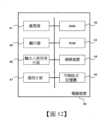
圖2係為本實施形態所述之解析度測定系統的構成之一例的圖示。如圖2所示,解析度測定系統1係含有相機10、顯示器20、電腦裝置30而被構成。相機10,係為作為解析度測定之對象的被驗相機,係為像是魚眼相機這類在攝影視野會產生變形的相機。此外,於圖2中從相機10所延伸出去的虛線箭頭,係表示相機10的攝角範圍之一例。顯示器20,係將測試圖卡等之影像予以顯示,該當影像係被相機10所攝影。電腦裝置30,係取得相機10的攝影影像資料,而一併使用顯示器中所被顯示的測試圖卡的影像資料,對測試圖卡執行變形修正所需之處理。顯示器20(測試圖卡)係只要被配置成,讓測試圖卡會包含有相機10的攝角內欲測定解析度之任意地點的方式而被攝影即可,不限定於特定之位置。但是,在進行該當地點之解析度之測定的期間,相機10與顯示器20之相對位置係被固定成不會變化。FIG2 is a diagram showing an example of the configuration of the resolution measurement system described in the present embodiment. As shown in FIG2, the resolution measurement system 1 is configured to include a
電腦裝置30係具備:資料輸出入部302、失真地圖生成部304、逆投影影像生成部306、解析度測定部308。The
資料輸出入部302,係與相機10或顯示器20進行各種資料的輸出入處理。例如,資料輸出入部302,係將相機10的攝影影像資料,從相機10透過有線或無線之網路而加以取得。又,資料輸出入部302,係亦可將該當攝影影像資料,透過可拆卸的可移除式記憶體而加以取得。又,資料輸出入部302,係將用來在顯示器20中顯示出測試圖卡等之影像所需之顯示資料,予以輸出。The data input/
失真地圖生成部304,係生成失真地圖,其係表示:第1測試圖卡(後述的棋盤格影像50等)之全像素之座標、與藉由在攝影視野中會產生變形的相機10所被攝影的攝影影像中的第1測試圖卡(後述的有變形之棋盤格影像50d等)之全像素之座標之對應關係。又,第1測試圖卡係為例如後述的像是棋盤格影像50等的格子狀之影像。失真地圖生成部304係例如,從相機10之攝影影像中的有發生變形之棋盤格影像50(第1測試圖卡)之各格子點之座標,藉由像是3次樣條補插這類的補插處理,而算出攝影影像中的有發生變形之第1測試圖卡之全像素之座標。The distortion
逆投影影像生成部306,係隨應於藉由已被失真地圖生成部304所生成之失真地圖而被表示的對應關係,而生成用來在攝影影像中的第1測試圖卡內(影像範圍內)的特定區域中進行解析度之測定所需之身為第2測試圖卡(後述的測定用測試圖卡的無變形之影像62等)之扭曲影像的扭曲測試圖卡(後述的有變形之測定用測試圖卡62d等)。已被生成的扭曲測試圖卡,其影像資料係被輸出至顯示器20,藉由顯示器20而被顯示輸出。或,已被生成之扭曲測試圖卡的影像資料亦可被輸出至印表機(未圖示)而列印輸出在紙上。The reverse projection
解析度測定部308,係使用逆投影影像生成部306中已被生成之扭曲測試圖卡而在上記特定區域所對應之相機10之攝影視野之一部分中執行對比法所致之解析度之測定。又,在執行解析度測定之際,已被逆投影影像生成部306所生成之扭曲測試圖卡,係被輸出至顯示器20。此外,於本實施形態中,已被逆投影影像生成部306所生成之扭曲測試圖卡,係在被相機10拍攝之際會被拍攝成變形已被修正(無變形)之影像,因此對比法所致之解析度之測定係可和先前之對比法同樣地被執行。The
又,亦可設計成,於逆投影影像生成部306中,會生成對應於複數個空間頻率的身為複數個第2測試圖卡之扭曲影像的複數個扭曲測試圖卡,於解析度測定部308中,係使用該當複數個扭曲測試圖卡來執行解析度之測定。 (失真地圖的生成方法)Furthermore, it can also be designed that in the back-projection
以下詳述失真地圖生成部304中的失真地圖的生成方法的具體例。於本實施形態中為了生成失真地圖,於相機10之攝角內的任意位置(包含有欲測定解析度之部分的區域)上,顯示器20中所被顯示的棋盤格之影像會被攝影。然後,基於所得到的該當棋盤格之攝影影像之座標點,藉由補插處理而求出棋盤格影像之全像素之變形。此外,作為補插處理係可舉出例如3次樣條補插處理等,但不限定於此。亦可使用其他的補插方法。表示該原始的棋盤格影像之像素與經由攝影而被扭曲的棋盤格影像之像素之對應關係的資料,係作為失真地圖而被保存。然後,基於該失真地圖,即使是在攝影視野中會產生變形的相機10,仍可生成能夠讓其進行對比法所致之解析度測定的測定用測試圖卡。A specific example of the method for generating a distorted map in the distorted
圖3係為相機10的攝影視野之一例的圖示。如圖3所示,首先,顯示器20中係顯示出棋盤格影像50來作為測試圖卡。以使得該棋盤格影像50會包含有相機10之攝角內的欲測定解析度之領域的方式而被拍到的方式,來調整顯示器20與相機10的相對位置。又,電腦裝置30的資料輸出入部302,係將如圖3所示的相機10的攝影影像之資料,從相機10加以取得。FIG. 3 is a diagram showing an example of the photographic field of view of the
接著參照圖4,圖4係為表示,棋盤格影像50之像素、與從相機10所取得之攝影影像中的有扭曲的棋盤格影像50d之像素之對應關係之一例的圖。在圖4的例子中,假設棋盤格影像50係為2560像素×1664像素之大小。Next, referring to Fig. 4, Fig. 4 is a diagram showing an example of the correspondence between the pixels of the checkerboard image 50 and the pixels of the distorted checkerboard image 50d in the photographic image acquired from the
圖5係為失真地圖的資料結構之一例的圖示。如圖5所示,於本實施形態中,失真地圖資料係可藉由,令測試圖卡50之全像素之座標(x, y)、與相機10之攝影影像中的有扭曲的測試圖卡50d之全像素之座標(x, y)做對應的2維陣列的方式,而被實現。於本例中由於測試圖卡(棋盤格影像)50係為2560像素×1664像素,因此失真地圖資料係可藉由,尺寸2560(像素)×1664(像素)×2(x座標, y座標)之2維陣列,而被表現(但是本例係僅為一例而並非限定於此)。更具體而言,於本例是測定棋盤格之格子點之各座標。然後,所被測定到的各座標,係可按照每一xy座標而被保存成矩陣。這些處理係可使用既存的軟體來進行。例如,可使用MathWorks(註冊商標)公司的產品「MATLAB」(註冊商標)的DetectCheckerboardPoints函數,來求出相機10之攝影影像中的棋盤格50d之各格子點之座標。FIG5 is a diagram showing an example of a distorted map data structure. As shown in FIG5, in this embodiment, the distorted map data can be realized by making a two-dimensional array that corresponds to the coordinates (x, y) of all pixels of the test chart 50 and the coordinates (x, y) of all pixels of the distorted test chart 50d in the photographic image of the
然後,基於已被求出的棋盤格影像50d之各格子點之座標,就可藉由補插處理而求出棋盤格影像50d之全像素之座標。該處理係可藉由例如,對棋盤格影像50之全像素,將棋盤格影像50d之x座標與y座標,分別藉由MathWorks公司的產品「MATLAB」的griddedInterpolant函數而進行2維補插,然後保存至失真地圖,即可加以實現。 (逆投影影像的生成方法)Then, based on the coordinates of each grid point of the checkerboard image 50d that have been obtained, the coordinates of all pixels of the checkerboard image 50d can be obtained by interpolation processing. This processing can be achieved by, for example, performing 2D interpolation of the x-coordinate and y-coordinate of the checkerboard image 50d for all pixels of the checkerboard image 50 using the griddedInterpolant function of the MathWorks product "MATLAB", and then saving the two-dimensional interpolation to the distorted map.(Method for generating back-projection image)
於失真地圖生成部304中一旦失真地圖被生成,則接下來,於逆投影影像生成部306中,進行解析度測定之際所被使用的測定用測試圖卡的逆投影影像,就會被生成。圖6係為相機之攝影影像中的對應於棋盤格影像領域的白色的測試圖卡影像50w、和其後所被描繪之測定用測試圖卡的無變形之影像62之一例的圖示。更具體而言,在表示有變形之棋盤格影像50d之影像範圍的白色的測試圖卡影像50w中,例如電腦裝置30的使用者係使用滑鼠等之輸入裝置而指定(描繪)表示欲測定解析度之地點的矩形61。然後,在該矩形61所被指定的地點中,描繪出測定用測試圖卡的無變形之影像62。Once the distortion map is generated in the distortion
接著,基於失真地圖,將測定用測試圖卡的無變形之影像62進行逆投影,生成有變形之測定用測試圖卡影像。更具體而言,隨應於測定用測試圖卡的無變形之影像62之全像素之座標,是對應於圖5所示的失真地圖之棋盤格影像50哪個座標(x, y),而將無變形之影像62之各像素之座標(x, y)進行逆轉換,藉此就可生成有變形之測定用測試圖卡影像。圖7係為測定用測試圖卡的無變形之影像62被逆投影而被生成的有變形之測定用測試圖卡62d之一例的圖示。Next, based on the distortion map, the undeformed image 62 of the measurement test chart is back-projected to generate a deformed measurement test chart image. More specifically, according to which coordinates (x, y) of the checkerboard image 50 of the distorted map shown in FIG. 5 the coordinates of all pixels of the undeformed image 62 of the measurement test chart correspond, the coordinates (x, y) of each pixel of the undeformed image 62 are inversely transformed, thereby generating a deformed measurement test chart image. FIG. 7 is a diagram showing an example of a deformed measurement test chart 62d generated by back-projecting the undeformed image 62 of the measurement test chart.
又,在解析度測定中是將亮度之變化轉換成頻率特性,因此必須確保亮度資料的線形性。然而,一般而言,數位相機的亮度特性會因為各式各樣的理由而不呈現線性,因此需要使用亮度為已知的測試圖卡(這裡是稱為「步階圖卡(step chart)」),來修正亮度資料的線形性。因此,與測定用測試圖卡同樣地,即使針對如圖8所示的步階圖卡,也會將其無變形之影像63進行逆投影而生成有變形之步階圖卡63d。In addition, in the resolution measurement, the change of brightness is converted into a frequency characteristic, so the linearity of the brightness data must be ensured. However, in general, the brightness characteristics of a digital camera are not linear for various reasons, so it is necessary to use a test chart with known brightness (here called a "step chart") to correct the linearity of the brightness data. Therefore, similar to the test chart for measurement, even for the step chart shown in FIG. 8, its non-deformed image 63 is back-projected to generate a deformed step chart 63d.
又,圖9係為,如以上所被生成之有變形之測定用測試圖卡影像62d被顯示於顯示器20,將該當測定用測試圖卡影像62d以相機10進行攝影之際的攝影視野10a之一例的圖示。可知於攝影視野10a中,測定用測試圖卡影像62a係和圖7的無變形之影像62同樣地,是以無變形之狀態而被拍到。藉此,相機10的攝影視野之中測定用測試圖卡影像62a所被拍到的地點上,就可進行對比法所致之解析度之測定。該解析度之測定,係可藉由先前之對比法之手法而進行。又,於相同的白色的測試圖卡影像50w中的其他地點上也同樣地進行解析度測定。此外,關於圖8中所說明的用來修正亮度資料之線形性所需之步階圖卡,也是和圖9同樣地,令有變形之步階圖卡影像63d被顯示於顯示器20,藉由以相機10來拍攝該當步階圖卡影像63d,於相機10的攝影視野10a中就會拍到無變形之步階圖卡。然後,在解析度測定執行之際,基於隨應於步階圖卡影像63、63d而被生成的亮度線性化LUT(Look-Up Table),來修正亮度資料。Furthermore, FIG. 9 is a diagram showing an example of a photographic field 10a in which the deformed test card image 62d for measurement generated as described above is displayed on the
又,在相機10的攝影視野之中於棋盤格影像50之範圍外進行解析度測定的情況下,係使顯示器20(測試圖卡)與相機10的相對位置做變化,使得進行解析度測定的地點被棋盤格影像所包含,且該當棋盤格影像50之全體是被收納在相機10之攝影視野中,重複上述的失真地圖之生成到測定用測試圖卡的逆投影影像之生成為止的處理,就可在相機的攝影視野中的複數地點上,進行解析度之測定。Furthermore, when the resolution is measured outside the range of the checkerboard image 50 in the photographic field of view of the
此外,於本實施形態中,雖然是假設在顯示器20中顯示出各種測試圖卡,但不限定於此。例如,測試圖卡亦可被印刷在紙上。例如在室外等顯示器的亮度可能會不足的環境下,將測試圖卡印刷在紙上等之方法是有效的。無論哪種方法,(顯示器20中所被顯示的、或被印刷在紙上的)測試圖卡,係只要被配置成,使得相機10之攝角內的欲測定解析度的任意地點被該當測試圖卡所包含即可。又,從棋盤格影像50生成失真地圖,生成有變形之測試圖卡62d並進行解析度之測定為止之期間,相機10與測試圖卡的相對位置,必須被固定成沒有變化。In addition, in the present embodiment, although it is assumed that various test charts are displayed on the
如以上般地生成失真地圖,基於該當失真地圖而生成有變形之測試圖卡,於相機10之攝角內的特定地點上就可使用對比法進行解析度測定。又,本實施形態所述之解析度測定方法中,係在生成失真地圖而型解析度測定為止之期間,只要求相機10與顯示器20(測試圖卡50、50d、62d、62a)的相對位置不要有變化,至於相機10與顯示器20(測試圖卡50、50d、62d、62a)之間的檢查距離、或相機10及顯示器20(測試圖卡50、50d、62d、62a)的位置並不限定於特定的狀態(可以在每次進行解析度測定時有所變更)。又,基於棋盤格影像50之像素之座標、與相機影像中的有變形之棋盤格50d之像素之座標的對應關係,而生成有變形之測試圖卡影像62d並執行對比法所致之解析度測定。因此,即使是扭曲特性式為未知的相機,仍可進行解析度測定。As described above, a distortion map is generated, and a deformed test chart is generated based on the distortion map, and the resolution can be measured using the contrast method at a specific point within the
順便一提,在先前的對比法中,一般而言會使用,可針對複數個空間頻率進行解析度測定的像是測試圖卡62的比較大的測試圖案。因此,在先前的對比法中,難以在相機10之攝角內的較窄的範圍中,測定解析度。相對於此,於本實施形態中,係如圖10所示,是作成了對應於複數個空間頻率的複數個測定用測試圖卡(條紋圖卡)62d。這些測定用測試圖卡也是如上述般地生成失真地圖,基於該當失真地圖而生成有變形之測試圖卡62d。然後,這些有變形之複數個測定用測試圖卡62d是以分時方式而在顯示器20的相同地點(對應於相機10之攝角內的欲執行解析度測定之位置)上被顯示,讓相機10拍攝之。藉此,於攝影影像中,測定用測試圖卡62d係以無變形之測定用測試圖卡的方式而被攝影,因此就可針對複數個空間頻率來進行解析度測定。藉由採用如此的測定用測試圖卡62d,就可解決先前之對比法中難以在較窄範圍內進行解析度測定的問題。 (處理流程)By the way, in the previous comparison method, a relatively large test pattern such as the test chart 62 is generally used, which can measure the resolution for multiple spatial frequencies. Therefore, in the previous comparison method, it is difficult to measure the resolution within a narrow range within the shooting angle of the
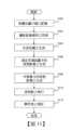
圖11係為本實施形態所述之解析度測定系統1的電腦裝置30中的處理之一例的流程圖。FIG. 11 is a flow chart showing an example of processing in the
於步驟S100中,相機10及顯示器20係被配置。相機10與顯示器20的相對位置,係在本處理流程結束為止,都被固定。In step S100, the
於步驟S102中,資料輸出入部302,係針對顯示器20中所被顯示的棋盤格影像50,將以相機10所拍攝到的有扭曲之棋盤格影像50d的攝影影像資料,加以取得。In step S102 , the data input/
於步驟S104中,失真地圖生成部304,係根據棋盤格影像50、和步驟S102中所被取得的有扭曲之棋盤格影像50d的攝影影像資料,而生成失真地圖。In step S104, the distorted
於步驟S106中,逆投影影像生成部306,係於白色的測試圖卡影像50w中被使用者以滑鼠等所指定的特定地點(矩形61)上,生成測定用測試圖卡的無變形之影像62。又,此時亦可生成,如圖10所示的複數個測定用測試圖卡影像的無變形之影像。又同樣地,於步驟S108中,逆投影影像生成部306係生成,用來修正亮度資料之線形性所需之步階圖卡的無變形之影像63。此外,步驟S106與S108之處理的順序亦可顛倒,亦可平行地被處理。In step S106, the back-projection
於步驟S110中,逆投影影像生成部306係基於失真地圖,將測定用測試圖卡的無變形之影像62進行逆投影,生成有變形之測定用測試圖卡影像62d。又,此時亦可生成,如圖10所示的複數個測定用測試圖卡影像62d。又,已被生成的有變形之測定用測試圖卡影像62d的影像資料,係被輸出至顯示器20。顯示器20,係將該當影像資料加以取得並予以顯示輸出。(或者亦可將有變形之測定用測試圖卡影像62d印刷在紙上。)同樣地,逆投影影像生成部306,係針對步階圖卡的無變形之影像63也進行逆投影,生成有變形之步階圖卡63d。已被生成的有變形之步階圖卡影像63d的影像資料,係被輸出至顯示器20。In step S110, the back-projection
於步驟S112中,藉由以相機10來拍攝(被顯示於顯示器20、或或被印刷在紙上的)有變形之測定用測試圖卡影像62d,就可使用無變形之測定用測試圖卡影像62a來執行對比法所致之解析度測定。又,在解析度測定執行之際,基於隨應於步階圖卡影像63、63d而被生成的亮度線性化LUT,來修正亮度資料。又,此時,於顯示器20中複數個測定用測試圖卡影像62d是以分時方式而被顯示輸出,藉此亦可針對複數個空間頻率來執行解析度測定。In step S112, by photographing the deformed test chart image 62d (displayed on the
此外,在相機10所拍攝到的有變形之棋盤格影像50d的影像範圍的其他地點上進行解析度測定的情況下,則重複步驟S106~S110之處理。In addition, when the resolution is measured at other locations within the image range of the deformed chessboard image 50d captured by the
然後,在相機10的攝影視野之中,在棋盤格影像50d之影像範圍以外之地點進行解析度測定的情況下,則以使得進行解析度測定之地點會被棋盤格影像50d所包含的方式,執行步驟S100之處理。然後,針對要進行該當解析度測定的地點,執行步驟S102以後之處理。Then, when the resolution measurement is performed at a point outside the image range of the checkerboard image 50d within the photographic field of view of the
此外,本處理流程所致之解析度測定方法,係亦可作為用來令電腦裝置執行所需之電腦程式的方式來加以實現。又,亦可將如此的電腦程式記錄在電腦裝置可讀出之記錄媒體中。亦即,可以具體實現一種內儲程式之電腦可讀取之記錄媒體,其特徵為,由電腦裝置將如此的電腦程式予以載入並執行後,可以完成上述的解析度測定方法。甚至,可以具體實現一種電腦程式產品,其特徵為,由電腦裝置將如此的電腦程式予以載入並執行後,可以完成上述的解析度測定方法。 (硬體構成)In addition, the resolution measurement method resulting from the present processing flow can also be implemented as a method for causing a computer device to execute a required computer program. Moreover, such a computer program can also be recorded in a recording medium readable by a computer device. That is, a computer-readable recording medium with a stored program can be specifically implemented, wherein the above-mentioned resolution measurement method can be completed after such a computer program is loaded and executed by a computer device. Even more, a computer program product can be specifically implemented, wherein the above-mentioned resolution measurement method can be completed after such a computer program is loaded and executed by a computer device.(Hardware structure)
上記所說明的電腦裝置30的構成,係可藉由與一般的電腦裝置相同的硬體構成來加以實現。圖12係為電腦裝置30的硬體構成之一例的圖示。圖12所示的電腦裝置40,作為一例,是具備:處理器41、RAM(Random Access Memory)42、ROM(Read Only Memory)43、內接的硬碟裝置44、外接硬碟裝置、CD、DVD、USB記憶體、記憶棒、SD卡等之可移除式記憶體45、用來讓使用者與電腦裝置40進行資料之交換所需之輸出入使用者介面46(鍵盤、滑鼠、觸控面板、揚聲器、麥克風、燈號等)、相機10、顯示器20、或可與其他裝置通訊的有線/無線之通訊介面47、顯示器48(亦可兼用作為顯示器20)。本實施形態所述之電腦裝置30的功能係例如,由處理器41,將硬碟裝置44或ROM43、可移除式記憶體45等中所預先儲存的程式,讀出至RAM42等之記憶體,將處理所需的上述之資料,從硬碟裝置44或ROM43、可移除式記憶體45等適宜讀出並執行程式,藉此就可加以實現。此外,圖12所示的硬體構成係僅止於一例,並非限定於此。The configuration of the
目前為止,雖然針對本發明的一實施形態做了說明,但本發明並不限定於上述的實施形態,在其技術思想的範圍內,當然可以用各種不同的形態來加以實施。Although one embodiment of the present invention has been described so far, the present invention is not limited to the above-mentioned embodiment and can be implemented in various forms within the scope of its technical concept.
又,本發明的範圍,係不限定於所被圖示或記載的例示性實施形態,亦包含可達成與本發明之目的具有均等效果所有實施形態。再者,本發明的範圍,係不限定於被各請求項所界定的發明之特徵組合,亦可在所有被揭露的各個特徵之中,藉由特定之特徵的任何所望之組合而被界定。Furthermore, the scope of the present invention is not limited to the exemplary embodiments shown or described, but includes all embodiments that can achieve the purpose of the present invention and have an equivalent effect. Furthermore, the scope of the present invention is not limited to the combination of features of the invention defined by each claim, but can be defined by any desired combination of specific features among all the disclosed features.
1:解析度測定系統 10:被驗相機 20:顯示器(測試圖卡) 30:電腦裝置 302:資料輸出入部 304:失真地圖生成部 306:逆投影影像生成部 308:解析度測定部 40:電腦裝置 41:處理器 42:RAM 43:ROM 44:硬碟裝置 45:可移除式記憶體 46:輸出入使用者介面 47:通訊介面 48:顯示器1: Resolution measurement system10: Test camera20: Display (test chart)30: Computer device302: Data input/output unit304: Distortion map generation unit306: Back-projection image generation unit308: Resolution measurement unit40: Computer device41: Processor42: RAM43: ROM44: Hard disk device45: Removable memory46: Input/output user interface47: Communication interface48: Display
[圖1]本發明的一實施形態所述之解析度測定系統的外觀之一例的圖示。 [圖2]本發明的一實施形態所述之解析度測定系統的構成之一例的圖示。 [圖3]相機的攝影視野之一例的圖示。 [圖4]表示棋盤格影像之像素,與扭曲的棋盤格影像之像素之對應關係之一例的圖。 [圖5]失真地圖的資料結構之一例的圖示。 [圖6]對應於攝影影像中的棋盤格影像領域的白色的測試圖卡影像、與其後所被描繪的測定用測試圖卡的無變形之影像之一例的圖示。 [圖7]將測定用測試圖卡的無變形之影像進行逆投影所被生成的有變形之測定用測試圖卡影像之一例的圖示。 [圖8]將步階圖卡的無變形之影像進行逆投影所被生成的有變形之步階圖卡影像之一例的圖示。 [圖9]將有變形之測定用測試圖卡影像以相機進行攝影之際的攝影視野之一例的圖示。 [圖10]對應於複數個空間頻率的複數個測定用測試圖卡之一例的圖示。 [圖11]本發明的一實施形態所述之解析度測定系統的電腦裝置中的處理之一例的流程圖。 [圖12]本發明的一實施形態所述之解析度測定系統的電腦裝置的硬體構成之一例的圖示。[FIG. 1] An example of the appearance of a resolution measurement system according to an embodiment of the present invention.[FIG. 2] An example of the configuration of a resolution measurement system according to an embodiment of the present invention.[FIG. 3] An example of a camera field of view.[FIG. 4] An example of a diagram showing the correspondence between pixels of a checkerboard image and pixels of a distorted checkerboard image.[FIG. 5] An example of a data structure of a distortion map.[FIG. 6] An example of a white test chart image corresponding to the checkerboard image area in a photographic image and an example of an undistorted image of a test chart for measurement drawn thereafter.[FIG. 7] An example of a distorted test chart image for measurement generated by back-projecting an undistorted image of a test chart for measurement.[Figure 8] An example of a deformed step chart image generated by back-projecting an undeformed image of the step chart.[Figure 9] An example of a photographic field of view when a deformed test chart image is photographed by a camera.[Figure 10] An example of a plurality of test charts for measurement corresponding to a plurality of spatial frequencies.[Figure 11] A flowchart of an example of processing in a computer device of a resolution measurement system according to an embodiment of the present invention.[Figure 12] An example of a hardware configuration of a computer device of a resolution measurement system according to an embodiment of the present invention.
Claims (6)
Translated fromChineseApplications Claiming Priority (2)
| Application Number | Priority Date | Filing Date | Title |
|---|---|---|---|
| JP2021-014283 | 2021-02-01 | ||
| JP2021014283AJP7304641B2 (en) | 2021-02-01 | 2021-02-01 | Chart generation method, resolution measurement method, resolution measurement system, and program |
Publications (2)
| Publication Number | Publication Date |
|---|---|
| TW202232936A TW202232936A (en) | 2022-08-16 |
| TWI858231Btrue TWI858231B (en) | 2024-10-11 |
Family
ID=82653240
Family Applications (1)
| Application Number | Title | Priority Date | Filing Date |
|---|---|---|---|
| TW110105722ATWI858231B (en) | 2021-02-01 | 2021-02-19 | Resolution measurement method, resolution measurement system, computer device and computer readable medium |
Country Status (7)
| Country | Link |
|---|---|
| US (1) | US20240121380A1 (en) |
| EP (1) | EP4286823A4 (en) |
| JP (1) | JP7304641B2 (en) |
| KR (1) | KR102811503B1 (en) |
| CN (1) | CN116829918A (en) |
| TW (1) | TWI858231B (en) |
| WO (1) | WO2022162953A1 (en) |
Families Citing this family (2)
| Publication number | Priority date | Publication date | Assignee | Title |
|---|---|---|---|---|
| CN115824282B (en)* | 2022-08-25 | 2024-07-12 | 廊坊市大华夏神农信息技术有限公司 | Calculation method and equipment suitable for detecting resolution of various sensors |
| CN119984765B (en)* | 2025-04-11 | 2025-08-01 | 浙江舜宇光学有限公司 | Measuring method and measuring system for view field angle of near-eye display module |
Citations (5)
| Publication number | Priority date | Publication date | Assignee | Title |
|---|---|---|---|---|
| JPH11142292A (en)* | 1997-11-05 | 1999-05-28 | Matsushita Electric Ind Co Ltd | MTF measurement chart and MTF measurement device |
| US20030035100A1 (en)* | 2001-08-02 | 2003-02-20 | Jerry Dimsdale | Automated lens calibration |
| TWI236840B (en)* | 2003-02-03 | 2005-07-21 | Photon Dynamics Inc | Method and apparatus for optical inspection of a display |
| US20140300754A1 (en)* | 2013-04-08 | 2014-10-09 | Omnivision Technologies, Inc. | Systems and methods for calibration of a 360 degree camera system |
| JP6539812B1 (en)* | 2018-07-18 | 2019-07-10 | ナルックス株式会社 | Inspection method of lens |
Family Cites Families (10)
| Publication number | Priority date | Publication date | Assignee | Title |
|---|---|---|---|---|
| US8681224B2 (en)* | 2007-06-26 | 2014-03-25 | Dublin City University | Method for high precision lens distortion calibration and removal |
| JP2010281626A (en)* | 2009-06-03 | 2010-12-16 | Opto Device Corporation Co Ltd | Device for inspecting optical characteristic |
| GB2482022A (en)* | 2010-07-16 | 2012-01-18 | St Microelectronics Res & Dev | Method for measuring resolution and aberration of lens and sensor |
| JP2015534734A (en)* | 2012-06-28 | 2015-12-03 | ペリカン イメージング コーポレイション | System and method for detecting defective camera arrays, optical arrays, and sensors |
| US10067029B2 (en)* | 2016-02-12 | 2018-09-04 | Google Llc | Systems and methods for estimating modulation transfer function in an optical system |
| EP3502647A4 (en)* | 2016-08-18 | 2019-12-18 | QD Laser, Inc. | Image inspection device, image inspection method, and image inspection device component |
| EP3529581A2 (en)* | 2016-10-18 | 2019-08-28 | Eyoto Group Limited | Lens examination equipment and method |
| CN108931357B (en)* | 2017-05-22 | 2020-10-23 | 宁波舜宇车载光学技术有限公司 | Test target and corresponding lens MTF detection system and method |
| EP3702750B1 (en)* | 2019-03-01 | 2025-07-02 | Valeo Vision | Method for correcting a light pattern, automotive lighting device and automotive lighting assembly |
| EP3715819A1 (en)* | 2019-03-27 | 2020-09-30 | Valeo Vision | Method for correcting a light pattern, automotive lighting device and automotive lighting assembly |
- 2021
- 2021-02-01JPJP2021014283Apatent/JP7304641B2/enactiveActive
- 2021-02-10USUS18/263,690patent/US20240121380A1/enactivePending
- 2021-02-10KRKR1020237029450Apatent/KR102811503B1/enactiveActive
- 2021-02-10EPEP21922962.2Apatent/EP4286823A4/enactivePending
- 2021-02-10WOPCT/JP2021/004940patent/WO2022162953A1/ennot_activeCeased
- 2021-02-10CNCN202180092268.0Apatent/CN116829918A/enactivePending
- 2021-02-19TWTW110105722Apatent/TWI858231B/enactive
Patent Citations (5)
| Publication number | Priority date | Publication date | Assignee | Title |
|---|---|---|---|---|
| JPH11142292A (en)* | 1997-11-05 | 1999-05-28 | Matsushita Electric Ind Co Ltd | MTF measurement chart and MTF measurement device |
| US20030035100A1 (en)* | 2001-08-02 | 2003-02-20 | Jerry Dimsdale | Automated lens calibration |
| TWI236840B (en)* | 2003-02-03 | 2005-07-21 | Photon Dynamics Inc | Method and apparatus for optical inspection of a display |
| US20140300754A1 (en)* | 2013-04-08 | 2014-10-09 | Omnivision Technologies, Inc. | Systems and methods for calibration of a 360 degree camera system |
| JP6539812B1 (en)* | 2018-07-18 | 2019-07-10 | ナルックス株式会社 | Inspection method of lens |
Also Published As
| Publication number | Publication date |
|---|---|
| KR20230140457A (en) | 2023-10-06 |
| JP7304641B2 (en) | 2023-07-07 |
| US20240121380A1 (en) | 2024-04-11 |
| KR102811503B1 (en) | 2025-05-22 |
| TW202232936A (en) | 2022-08-16 |
| WO2022162953A1 (en) | 2022-08-04 |
| EP4286823A1 (en) | 2023-12-06 |
| JP2022117666A (en) | 2022-08-12 |
| EP4286823A4 (en) | 2024-11-13 |
| CN116829918A (en) | 2023-09-29 |
Similar Documents
| Publication | Publication Date | Title |
|---|---|---|
| JP7372199B2 (en) | Projection system, projection device, and calibration method for its displayed image | |
| CN109104596B (en) | Projection system and correction method of display image | |
| JP5521855B2 (en) | Projection image area detection device | |
| TWI703870B (en) | Projector apparatus, projector system and an image calibration method | |
| JP2014131257A (en) | Image correction system, image correction method, and program | |
| TWI858231B (en) | Resolution measurement method, resolution measurement system, computer device and computer readable medium | |
| JP5644461B2 (en) | Image processing apparatus and program | |
| JP2002057879A (en) | Image processing apparatus, image processing method, and computer-readable recording medium | |
| JP2019220887A (en) | Image processing system, image processing method, and program | |
| JP2003283804A (en) | Method and system for correcting curvature of binding | |
| CN115086631B (en) | Image generation method and information processing device | |
| JP2007142495A (en) | Planar projection apparatus and planar projection program | |
| JP6742180B2 (en) | MTF measuring device and its program | |
| JP2022117666A5 (en) | Chart generation method, resolution measurement method, resolution measurement system, and program | |
| JP2005018195A (en) | Image processing apparatus and image processing program | |
| JP2004165944A (en) | Projection information correction method, projection information correction device, program, and recording medium | |
| JP7206739B2 (en) | Acquisition equipment and program | |
| JP2005266042A (en) | Image geometric correction method and correction apparatus | |
| CN102802528B (en) | X-ray diagnostic device and X-ray image trimming method | |
| CN116320333B (en) | Transparent screen insertion method, projection equipment and computer storage medium | |
| JP6230001B2 (en) | Image correction apparatus, image correction method, and program | |
| CN119027759B (en) | Training sample generation method and device, electronic equipment and readable storage medium | |
| KR20180091794A (en) | Method of projection mapping | |
| JP2019041197A (en) | Test chart, test chart generation device, measuring device, test chart generation method, and program | |
| CN120031972A (en) | Projection equipment calibration method, device, projection equipment and storage medium |