TWI858210B - Water vapor treatment device and water vapor treatment method, substrate treatment system, and dry etching method - Google Patents
Water vapor treatment device and water vapor treatment method, substrate treatment system, and dry etching methodDownload PDFInfo
- Publication number
- TWI858210B TWI858210BTW109146121ATW109146121ATWI858210BTW I858210 BTWI858210 BTW I858210BTW 109146121 ATW109146121 ATW 109146121ATW 109146121 ATW109146121 ATW 109146121ATW I858210 BTWI858210 BTW I858210B
- Authority
- TW
- Taiwan
- Prior art keywords
- opening
- water vapor
- chamber
- upper chamber
- aforementioned
- Prior art date
Links
Images


Classifications
- H—ELECTRICITY
- H01—ELECTRIC ELEMENTS
- H01L—SEMICONDUCTOR DEVICES NOT COVERED BY CLASS H10
- H01L21/00—Processes or apparatus adapted for the manufacture or treatment of semiconductor or solid state devices or of parts thereof
- H01L21/67—Apparatus specially adapted for handling semiconductor or electric solid state devices during manufacture or treatment thereof; Apparatus specially adapted for handling wafers during manufacture or treatment of semiconductor or electric solid state devices or components ; Apparatus not specifically provided for elsewhere
- H01L21/67005—Apparatus not specifically provided for elsewhere
- H01L21/67011—Apparatus for manufacture or treatment
- H01L21/67017—Apparatus for fluid treatment
- H01L21/67028—Apparatus for fluid treatment for cleaning followed by drying, rinsing, stripping, blasting or the like
- H—ELECTRICITY
- H01—ELECTRIC ELEMENTS
- H01L—SEMICONDUCTOR DEVICES NOT COVERED BY CLASS H10
- H01L21/00—Processes or apparatus adapted for the manufacture or treatment of semiconductor or solid state devices or of parts thereof
- H01L21/02—Manufacture or treatment of semiconductor devices or of parts thereof
- H01L21/02041—Cleaning
- H01L21/02057—Cleaning during device manufacture
- H01L21/02068—Cleaning during device manufacture during, before or after processing of conductive layers, e.g. polysilicon or amorphous silicon layers
- H01L21/02071—Cleaning during device manufacture during, before or after processing of conductive layers, e.g. polysilicon or amorphous silicon layers the processing being a delineation, e.g. RIE, of conductive layers
- H—ELECTRICITY
- H01—ELECTRIC ELEMENTS
- H01L—SEMICONDUCTOR DEVICES NOT COVERED BY CLASS H10
- H01L21/00—Processes or apparatus adapted for the manufacture or treatment of semiconductor or solid state devices or of parts thereof
- H01L21/02—Manufacture or treatment of semiconductor devices or of parts thereof
- H01L21/04—Manufacture or treatment of semiconductor devices or of parts thereof the devices having potential barriers, e.g. a PN junction, depletion layer or carrier concentration layer
- H01L21/18—Manufacture or treatment of semiconductor devices or of parts thereof the devices having potential barriers, e.g. a PN junction, depletion layer or carrier concentration layer the devices having semiconductor bodies comprising elements of Group IV of the Periodic Table or AIIIBV compounds with or without impurities, e.g. doping materials
- H01L21/30—Treatment of semiconductor bodies using processes or apparatus not provided for in groups H01L21/20 - H01L21/26
- H01L21/31—Treatment of semiconductor bodies using processes or apparatus not provided for in groups H01L21/20 - H01L21/26 to form insulating layers thereon, e.g. for masking or by using photolithographic techniques; After treatment of these layers; Selection of materials for these layers
- H01L21/3205—Deposition of non-insulating-, e.g. conductive- or resistive-, layers on insulating layers; After-treatment of these layers
- H01L21/321—After treatment
- H01L21/3213—Physical or chemical etching of the layers, e.g. to produce a patterned layer from a pre-deposited extensive layer
- H01L21/32133—Physical or chemical etching of the layers, e.g. to produce a patterned layer from a pre-deposited extensive layer by chemical means only
- H01L21/32135—Physical or chemical etching of the layers, e.g. to produce a patterned layer from a pre-deposited extensive layer by chemical means only by vapour etching only
- H01L21/32136—Physical or chemical etching of the layers, e.g. to produce a patterned layer from a pre-deposited extensive layer by chemical means only by vapour etching only using plasmas
- H—ELECTRICITY
- H01—ELECTRIC ELEMENTS
- H01L—SEMICONDUCTOR DEVICES NOT COVERED BY CLASS H10
- H01L21/00—Processes or apparatus adapted for the manufacture or treatment of semiconductor or solid state devices or of parts thereof
- H01L21/67—Apparatus specially adapted for handling semiconductor or electric solid state devices during manufacture or treatment thereof; Apparatus specially adapted for handling wafers during manufacture or treatment of semiconductor or electric solid state devices or components ; Apparatus not specifically provided for elsewhere
- H01L21/67005—Apparatus not specifically provided for elsewhere
- H01L21/67011—Apparatus for manufacture or treatment
- H01L21/67017—Apparatus for fluid treatment
- H01L21/67023—Apparatus for fluid treatment for general liquid treatment, e.g. etching followed by cleaning
- H—ELECTRICITY
- H01—ELECTRIC ELEMENTS
- H01L—SEMICONDUCTOR DEVICES NOT COVERED BY CLASS H10
- H01L21/00—Processes or apparatus adapted for the manufacture or treatment of semiconductor or solid state devices or of parts thereof
- H01L21/67—Apparatus specially adapted for handling semiconductor or electric solid state devices during manufacture or treatment thereof; Apparatus specially adapted for handling wafers during manufacture or treatment of semiconductor or electric solid state devices or components ; Apparatus not specifically provided for elsewhere
- H01L21/67005—Apparatus not specifically provided for elsewhere
- H01L21/67011—Apparatus for manufacture or treatment
- H01L21/67017—Apparatus for fluid treatment
- H01L21/67063—Apparatus for fluid treatment for etching
- H01L21/67069—Apparatus for fluid treatment for etching for drying etching
- H—ELECTRICITY
- H01—ELECTRIC ELEMENTS
- H01L—SEMICONDUCTOR DEVICES NOT COVERED BY CLASS H10
- H01L21/00—Processes or apparatus adapted for the manufacture or treatment of semiconductor or solid state devices or of parts thereof
- H01L21/67—Apparatus specially adapted for handling semiconductor or electric solid state devices during manufacture or treatment thereof; Apparatus specially adapted for handling wafers during manufacture or treatment of semiconductor or electric solid state devices or components ; Apparatus not specifically provided for elsewhere
- H01L21/67005—Apparatus not specifically provided for elsewhere
- H01L21/67011—Apparatus for manufacture or treatment
- H01L21/67126—Apparatus for sealing, encapsulating, glassing, decapsulating or the like
- H—ELECTRICITY
- H01—ELECTRIC ELEMENTS
- H01L—SEMICONDUCTOR DEVICES NOT COVERED BY CLASS H10
- H01L21/00—Processes or apparatus adapted for the manufacture or treatment of semiconductor or solid state devices or of parts thereof
- H01L21/67—Apparatus specially adapted for handling semiconductor or electric solid state devices during manufacture or treatment thereof; Apparatus specially adapted for handling wafers during manufacture or treatment of semiconductor or electric solid state devices or components ; Apparatus not specifically provided for elsewhere
- H01L21/67005—Apparatus not specifically provided for elsewhere
- H01L21/67011—Apparatus for manufacture or treatment
- H01L21/67155—Apparatus for manufacturing or treating in a plurality of work-stations
- H01L21/67161—Apparatus for manufacturing or treating in a plurality of work-stations characterized by the layout of the process chambers
- H01L21/67178—Apparatus for manufacturing or treating in a plurality of work-stations characterized by the layout of the process chambers vertical arrangement
- H—ELECTRICITY
- H01—ELECTRIC ELEMENTS
- H01L—SEMICONDUCTOR DEVICES NOT COVERED BY CLASS H10
- H01L21/00—Processes or apparatus adapted for the manufacture or treatment of semiconductor or solid state devices or of parts thereof
- H01L21/67—Apparatus specially adapted for handling semiconductor or electric solid state devices during manufacture or treatment thereof; Apparatus specially adapted for handling wafers during manufacture or treatment of semiconductor or electric solid state devices or components ; Apparatus not specifically provided for elsewhere
- H01L21/677—Apparatus specially adapted for handling semiconductor or electric solid state devices during manufacture or treatment thereof; Apparatus specially adapted for handling wafers during manufacture or treatment of semiconductor or electric solid state devices or components ; Apparatus not specifically provided for elsewhere for conveying, e.g. between different workstations
- H01L21/67739—Apparatus specially adapted for handling semiconductor or electric solid state devices during manufacture or treatment thereof; Apparatus specially adapted for handling wafers during manufacture or treatment of semiconductor or electric solid state devices or components ; Apparatus not specifically provided for elsewhere for conveying, e.g. between different workstations into and out of processing chamber
- H01L21/67742—Mechanical parts of transfer devices
Landscapes
- Engineering & Computer Science (AREA)
- Physics & Mathematics (AREA)
- Computer Hardware Design (AREA)
- Condensed Matter Physics & Semiconductors (AREA)
- General Physics & Mathematics (AREA)
- Manufacturing & Machinery (AREA)
- Microelectronics & Electronic Packaging (AREA)
- Power Engineering (AREA)
- Robotics (AREA)
- Plasma & Fusion (AREA)
- Chemical & Material Sciences (AREA)
- Chemical Kinetics & Catalysis (AREA)
- General Chemical & Material Sciences (AREA)
- Drying Of Semiconductors (AREA)
- Thin Film Transistor (AREA)
Abstract
Translated fromChineseDescription
Translated fromChinese本揭示關於水蒸氣處理裝置與水蒸氣處理方法、基板處理系統、以及乾蝕刻方法。The present invention discloses a water vapor processing device and a water vapor processing method, a substrate processing system, and a dry etching method.
專利文獻1揭示連接到藉由鹵素類氣體之電漿對被處理體實施處理的被處理體處理室,且具備對內部之被處理體供給高溫水蒸氣的高溫水蒸氣供給裝置之大氣搬送室。依據專利文獻1揭示之大氣搬送室,可以促進反應生成物中之鹵素之還原,促進反應生成物之分解。[先前技術文獻][專利文獻]
[專利文獻1]特開2006-261456號公報[Patent Document 1] Japanese Patent Application No. 2006-261456
[發明所欲解決的課題][The problem that the invention is trying to solve]
本揭示提供針對已實施了基於處理氣體的處理之基板,可以在高生產性之狀態下進行水蒸氣處理的水蒸氣處理裝置及水蒸氣處理方法、基板處理系統、以及乾蝕刻方法。[解決課題的手段]The present disclosure provides a water vapor treatment device and a water vapor treatment method, a substrate treatment system, and a dry etching method that can perform water vapor treatment under high productivity on a substrate that has been treated with a treatment gas.[Means for Solving the Problem]
本揭示之一態樣的水蒸氣處理裝置,係藉由水蒸氣針對已實施了基於處理氣體的處理之基板進行處理,並且經由搬送裝置具有的第一閘門在與前述搬送裝置之間進行前述基板之傳遞的水蒸氣處理裝置,該水蒸氣處理裝置具有:上下堆疊的上腔室和下腔室;及隔離器,其介於前述上腔室和前述下腔室與前述第一閘門之間,且連接到前述上腔室、前述下腔室、和前述第一閘門;前述上腔室具備第一開口,前述下腔室具備第二開口,前述隔離器具備分別連通於前述第一開口與前述第二開口的第三開口與第四開口,前述第三開口與前述第四開口分別連通於前述第一閘門具備的第五開口與第六開口,前述上腔室和前述下腔室係與共同的或個別的水蒸氣之氣化器連通,前述隔離器,係在前述第三開口的周圍具備第一調溫部,且在前述第四開口的周圍具備第二調溫部。[發明效果]One aspect of the present disclosure is a water vapor treatment device, which processes a substrate that has been treated with a treatment gas by water vapor, and transfers the substrate between the transfer device and the transfer device through a first gate of the transfer device. The water vapor treatment device has: an upper chamber and a lower chamber stacked up and down; and an isolator, which is between the upper chamber and the lower chamber and the first gate, and is connected to the upper chamber, the lower chamber, and the first gate; The upper chamber has a first opening, the lower chamber has a second opening, the isolator has a third opening and a fourth opening respectively connected to the first opening and the second opening, the third opening and the fourth opening are respectively connected to the fifth opening and the sixth opening of the first gate,the upper chamber and the lower chamber are connected to a common or individual vaporizer of water vapor,the isolator has a first temperature control part around the third opening, and a second temperature control part around the fourth opening.[Effect of the invention]
依據本揭示,針對已實施了基於處理氣體的處理之基板,可以在高生產性之狀態下進行水蒸氣處理。According to the present disclosure, a water vapor treatment can be performed with high productivity on a substrate that has been subjected to a treatment gas-based treatment.
以下,參照圖面說明本揭示之實施形態的水蒸氣處理裝置及水蒸氣處理方法以及基板處理系統。此外,本說明書及圖面中,實質上相同的構成要素附加相同的符號並省略重複的說明。Hereinafter, the water vapor treatment device, water vapor treatment method and substrate treatment system of the embodiment of the present disclosure will be described with reference to the drawings. In addition, in the present specification and drawings, substantially the same components are given the same symbols and repeated descriptions are omitted.
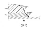
[實施形態]<應用了After treatment處理的薄膜電晶體之一例>首先,參照圖1至圖3說明藉由本揭示之實施形態的水蒸氣處理裝置實施After treatment處理的薄膜電晶體之一例。此處,圖1係表示應用了實施形態的水蒸氣處理裝置的After treatment處理的薄膜電晶體之一例的縱剖面圖。此外,圖2係表示蝕刻處理後之電極附近之狀態的示意圖,圖3係表示After treatment處理後之電極附近之狀態的示意圖。[Implementation form]<An example of a thin film transistor subjected to after-treatment>First, an example of a thin film transistor subjected to after-treatment using a water vapor treatment device according to an implementation form of the present disclosure will be described with reference to FIGS. 1 to 3. Here, FIG. 1 is a longitudinal cross-sectional view of an example of a thin film transistor subjected to after-treatment using a water vapor treatment device according to an implementation form. In addition, FIG. 2 is a schematic diagram showing a state near an electrode after etching, and FIG. 3 is a schematic diagram showing a state near an electrode after after-treatment.
液晶顯示裝置(Liquid Crystal Display:LCD)等之平板顯示器(Flat Panel Display:FPD)使用的例如薄膜電晶體(Thin Film Transistor:TFT)被形成在玻璃基板等之基板G之上。具體言之為,藉由在基板G之上實施閘極電極或閘極絶緣膜、半導體層等之圖案化並依序堆疊來形成TFT。此外,FPD用基板之平面尺寸隨著世代之推移而大規模化,基板處理系統500(參照圖4)處理的基板G之平面尺寸例如至少包含從第6世代之1500mm×1800mm左右之尺寸至第10.5世代之3000mm×3400mm左右之尺寸。此外,基板G之厚度為0.2mm至數mm左右。For example, thin film transistors (TFTs) used in flat panel displays (FPDs) such as liquid crystal displays (LCDs) are formed on substrates G such as glass substrates. Specifically, TFTs are formed by patterning gate electrodes or gate insulating films, semiconductor layers, etc. on substrate G and stacking them in sequence. In addition, the planar dimensions of FPD substrates are becoming larger with each generation, and the planar dimensions of substrates G processed by substrate processing system 500 (see FIG. 4 ) range from about 1500 mm×1800 mm for the 6th generation to about 3000 mm×3400 mm for the 10.5th generation, for example. In addition, the thickness of substrate G is about 0.2 mm to several mm.
圖1係表示通道蝕刻型之底閘極型結構之TFT。圖示的TFT,係在玻璃基板G(基板之一例)上形成閘極電極P1,在其上形成由SiN膜等構成的閘極絶緣膜F1,此外,在其之上層堆疊表面被n+摻雜的a-Si或氧化物半導體之半導體層F2。在半導體層F2之上層側形成金屬膜,該金屬膜被蝕刻,藉此而形成源極電極P2(電極之一例)與汲極電極P3(電極之一例)。FIG1 shows a TFT of a channel-etched bottom-gate structure. The TFT shown in the figure has a gate electrode P1 formed on a glass substrate G (an example of a substrate), a gate insulating film F1 composed of a SiN film or the like formed thereon, and a semiconductor layer F2 of a-Si or an oxide semiconductor whose surface is n+ doped is stacked thereon. A metal film is formed on the upper layer side of the semiconductor layer F2, and the metal film is etched to form a source electrode P2 (an example of an electrode) and a drain electrode P3 (an example of an electrode).
形成源極電極P2與汲極電極P3之後,對n+摻雜的半導體層F2的表面進行蝕刻,形成TFT中的通道部。接著,為了保護表面而形成例如由SiN膜形成的鈍化膜(未圖示)。接著,經由形成在鈍化膜的表面的接觸孔使源極電極P2或汲極電極P3連接到ITO(Indium Tin Oxide)等之未圖示之透明電極,該透明電極連接到驅動電路或驅動電極,藉此而形成FPD。此外,除了圖示例之底閘極型結構之TFT以外,還有頂閘極型結構之TFT等。After forming the source electrode P2 and the drain electrode P3, the surface of the n+ doped semiconductor layer F2 is etched to form the channel portion of the TFT. Next, a passivation film (not shown) such as a SiN film is formed to protect the surface. Next, the source electrode P2 or the drain electrode P3 is connected to an unillustrated transparent electrode such as ITO (Indium Tin Oxide) through a contact hole formed on the surface of the passivation film, and the transparent electrode is connected to a driving circuit or a driving electrode, thereby forming an FPD. In addition, in addition to the bottom gate type TFT shown in the example, there are also top gate type TFTs.
圖示的TFT中,作為用來形成源極電極P2與汲極電極P3的金屬膜可以使用例如包含Al的多層結構之金屬膜(多層金屬膜)。更具體言之為,可以使用從下層側依序堆疊有鈦(Ti)膜、鋁(Al)膜、鈦膜的Ti/Al/Ti結構之金屬膜或從下層側依序堆疊有鉬(Mo)膜、鋁膜、鉬膜的Mo/Al/Mo結構之金屬膜等。如圖1所示,例如在Ti/Al/Ti結構之金屬膜的表面圖案化阻劑膜F3。針對該金屬膜使用氯氣(Cl2)或三氯化硼(BCl3)、四氯化碳(CCl4)等氯系之蝕刻氣體(鹵素類之蝕刻氣體)之任一種氣體,或混合了彼等中之至少二種以上的混合氣體進行乾蝕刻處理。藉由該乾蝕刻處理形成源極電極P2與汲極電極P3。此外,使用Mo/Al/Mo結構之金屬膜之情況下,除了可以使用上述氯系之蝕刻氣體以外,針對鉬膜亦可以使用六氟化硫(SF6)等之氟系之蝕刻氣體進行乾蝕刻處理。In the illustrated TFT, a metal film having a multi-layer structure (multi-layer metal film) containing, for example, Al can be used as a metal film for forming a source electrode P2 and a drain electrode P3. More specifically, a metal film having a Ti/Al/Ti structure in which a titanium (Ti) film, an aluminum (Al) film, and a titanium film are stacked in sequence from the lower layer side, or a metal film having a Mo/Al/Mo structure in which a molybdenum (Mo) film, an aluminum film, and a Molybdenum film are stacked in sequence from the lower layer side can be used. As shown in FIG. 1 , for example, a resist film F3 is patterned on the surface of the metal film having the Ti/Al/Ti structure. The metal film is subjected to dry etching using any one of chlorine (Cl2 ) or chlorine-based etching gases (halogen-based etching gases) such as boron trichloride (BCl3 ) and carbon tetrachloride (CCl4 ), or a mixed gas of at least two of them. The source electrode P2 and the drain electrode P3 are formed by the dry etching process. In addition, when a metal film of a Mo/Al/Mo structure is used, in addition to the above-mentioned chlorine-based etching gas, a fluorine-based etching gas such as sulfur hexafluoride (SF6 ) can also be used for dry etching of a molybdenum film.
如上所述,由於使用氯系之蝕刻氣體來進行源極電極P2或汲極電極P3之圖案化時,如圖2所示,氯(Cl)有可能附著在阻劑膜F3。此外,在已蝕刻的金屬膜即電極P2(P3)上亦有可能附著氯或氯與鋁之化合物亦即氯化鋁(氯系化合物)。若將附著有氯的狀態之TFT為了之後之阻劑膜F3之剝離而進行大氣搬送時,阻劑膜F3或電極P2(P3)上附著的氯與大氣中之水分起反應而生成鹽酸,有可能成為導致電極P2(P3)之腐蝕的因素。此處,作為後處理雖可以利用四氟化碳(CF4)與氧(O2)之混合氣體生成的電漿來處理基板G,並除去氯的方法,但是若使用SiN膜作為金屬膜之底層膜時,該後處理時SiN膜有可能被刮擦。此外,金屬膜由Mo/Al/Mo構成時,該後處理時鉬膜被刮擦,而在鉬膜有可能產生底切(undercut)。As described above, when the source electrode P2 or the drain electrode P3 is patterned using a chlorine-based etching gas, chlorine (Cl) may adhere to the resist film F3 as shown in FIG2. In addition, chlorine or a compound of chlorine and aluminum, i.e., aluminum chloride (chlorine-based compound), may also adhere to the etched metal film, i.e., the electrode P2 (P3). If the TFT with chlorine attached is transported in the atmosphere in order to subsequently peel off the resist film F3, the chlorine attached to the resist film F3 or the electrode P2 (P3) reacts with the moisture in the atmosphere to generate hydrochloric acid, which may become a factor causing corrosion of the electrode P2 (P3). Here, as a post-treatment, although the substrate G can be treated with plasma generated by a mixed gas of carbon tetrafluoride (CF4 ) and oxygen (O2 ) to remove chlorine, if a SiN film is used as the base film of the metal film, the SiN film may be scratched during the post-treatment. In addition, when the metal film is composed of Mo/Al/Mo, the molybdenum film may be scratched during the post-treatment, and undercut may occur in the molybdenum film.
因此,本實施形態中,針對使用氯系之蝕刻氣體進行蝕刻處理而形成了電極P2(P3)之後之基板G,進行供給水蒸氣(H2O水蒸氣,非電漿水蒸氣)的水蒸氣處理(以下稱為「After treatment」)。藉由該水蒸氣處理除去電極P2(P3)上附著的氯。亦即,如圖3所示,H2O水蒸氣與電極P2(P3)上附著的氯或氯系化合物起反應而生成氯化氫(HCl),氯化氫從電極P2(P3)脫離而將氯或氯系化合物除去。該情況下,和在大氣中的氯與水分之反應不同,由於在稀薄的環境下可以快速地成為氯化氫離開空間,不會凝縮成為鹽。Therefore, in this embodiment, a water vapor treatment (hereinafter referred to as "after treatment") is performed by supplying water vapor (H2O water vapor, non-plasma water vapor) to the substrate G after the electrode P2 (P3) is formed by etching using a chlorine-based etching gas. The chlorine attached to the electrode P2 (P3) is removed by the water vapor treatment. That is, as shown in FIG3, theH2O water vapor reacts with the chlorine or chlorine-based compound attached to the electrode P2 (P3) to generate hydrogen chloride (HCl), and the hydrogen chloride is detached from the electrode P2 (P3) to remove the chlorine or chlorine-based compound. In this case, unlike the reaction between chlorine and water in the atmosphere, in a dilute environment it can quickly become hydrogen chloride and leave the air, and will not condense into salt.
<實施形態的基板處理系統>接著,參照圖4對實施形態的基板處理系統之一例進行說明。此處,圖4係表示實施形態的基板處理系統之一例的俯視圖。<Substrate processing system of the embodiment>Next, an example of a substrate processing system of the embodiment will be described with reference to FIG4. Here, FIG4 is a top view showing an example of a substrate processing system of the embodiment.
基板處理系統500為群集設備(Cluster tool),係多腔室型,構成為在真空氛圍下可以執行串列處理的系統。在基板處理系統500中,在配設於中央的俯視狀態下六角形之搬送裝置20(搬送腔室,亦稱為輸送模組)之一邊,經由閘閥12安裝有裝載鎖定腔室10。此外,在搬送裝置20的其他四邊,分別經由第二閘門22B(閘閥)安裝有四個製程腔室30A、30B、30C、30D(亦稱為製程模組)。此外,在搬送裝置20的剩餘之一邊,經由第一閘門22A(閘閥)安裝有本實施形態的水蒸氣處理裝置100(後處理腔室(After treatment chamber))。The
以各腔室都成為同一程度之真空氛圍的方式進行控制,開啟第一閘門22A和第二閘門22B而在搬送裝置20與各腔室之間進行基板G之傳遞時,以不產生腔室間之壓力變動的方式進行調整。The vacuum atmosphere in each chamber is controlled to be the same, and when the
裝載鎖定腔室10經由閘閥11連接到載具(未圖示),載具內收容有載置於載具載置部(未圖示)上的多片基板G。裝載鎖定腔室10構成為內部之壓力氛圍可以在常壓氛圍與真空氛圍之間切換,在與載具之間進行基板G之傳遞。The
裝載鎖定腔室10例如以二段堆疊,在各別的裝載鎖定腔室10內設置有保持基板G的支架14或進行基板G之位置調節的定位器13。裝載鎖定腔室10被控制為真空氛圍之後,開啟閘閥12使其與同樣被控制為真空氛圍的搬送裝置20連通,從裝載鎖定腔室10沿著X2方向將基板G傳送至搬送裝置20。The
在搬送裝置20內搭載有在圓周方向的X1方向自由旋轉,並且向各腔室側自由滑動的搬送機構21。搬送機構21將從裝載鎖定腔室10傳遞來的基板G搬送至期望之腔室,藉由開啟第一閘門22A和第二閘門22B,而將基板G傳遞至調整成為與裝載鎖定腔室10為同一程度之真空氛圍的各腔室。The
圖示例的製程腔室30A、30B、30C、30D都是電漿處理裝置,在各腔室中都是進行使用鹵素系之蝕刻氣體(氯系之蝕刻氣體)的乾蝕刻處理。關於基板處理系統500中的基板G之處理之一連串的流程,首先,從搬送裝置20將基板G傳遞至製程腔室30A,在製程腔室30A中實施乾蝕刻處理。實施了乾蝕刻處理的基板G係被傳遞至搬送裝置20(以上,基板G係朝X3方向移動)。The
如參照圖2之上述說明,在傳遞至搬送裝置20的基板G上,係在形成在基板G的表面的源極電極P2和汲極電極P3附著有氯或氯系化合物。因此,從搬送裝置20將基板G傳遞至水蒸氣處理裝置100,在水蒸氣處理裝置100中進行基於水蒸氣處理的After treatment。藉由After treatment從電極P2(P3)除去氯或氯系化合物,並將已除去了氯等的基板G傳遞至搬送裝置20(以上,基板G係朝X7方向移動)。As described above with reference to FIG. 2 , on the substrate G transferred to the
以下,同樣地進行在搬送裝置20與製程腔室30B之間之X4方向的基板G之傳遞,進行在搬送裝置20與水蒸氣處理裝置100之間之X7方向的基板G之傳遞。此外,進行在搬送裝置20與製程腔室30C之間之X5方向的基板G之傳遞,進行在搬送裝置20與水蒸氣處理裝置100之間之X7方向的基板G之傳遞。此外,進行在搬送裝置20與製程腔室30D之間之X6方向的基板G之傳遞,進行在搬送裝置20與水蒸氣處理裝置100之間之X7方向的基板G之傳遞。Hereinafter, similarly, the substrate G is transferred in the X4 direction between the
如上所述,基板處理系統500具有:進行使用了氯系之蝕刻氣體的乾蝕刻處理(電漿蝕刻處理)的多個蝕刻腔室;和進行基於水蒸氣處理的After treatment的水蒸氣處理裝置100。因此,構成為依據將各蝕刻腔室中的基板G之蝕刻處理,和在水蒸氣處理裝置100中的基於水蒸氣處理的After treatment設為一連串之序列的製程配方,在每個蝕刻腔室進行該序列的群集設備。在基板處理系統500中,藉由將以下詳細說明的水蒸氣處理裝置100配置為上下二段,可以形成更高生產性的群集設備。As described above, the
此外,各製程腔室也可以都是進行乾蝕刻處理的形態以外之形態。例如各製程腔室可以是序列地進行CVD(Chemical Vaper Deposition)處理或PVD(Physical Vaper Deposition)處理等之成膜處理、和進行蝕刻處理的形態之群集設備。此外,構成群集設備的搬送裝置的俯視形狀不限定於圖示例之六角形狀,可以適用與連接的製程腔室之數目對應的多角形狀之搬送裝置。In addition, each process chamber may be in a form other than a form for performing dry etching. For example, each process chamber may be a cluster device that sequentially performs film forming processes such as CVD (Chemical Vaper Deposition) or PVD (Physical Vaper Deposition) and etching. In addition, the top view shape of the transport device constituting the cluster device is not limited to the hexagonal shape shown in the example, and a polygonal transport device corresponding to the number of connected process chambers may be applied.
<實施形態的水蒸氣處理裝置>接著,參照圖5至圖8說明實施形態的水蒸氣處理裝置之一例。圖5係實施形態的水蒸氣處理裝置之一例之縱剖面圖。此外,圖6係表示圖5之VI-VI線的視圖,係表示上腔室和下腔室之縱剖面圖,圖7係表示圖5之VII-VII線的視圖,係表示實施形態的水蒸氣處理裝置之一例之橫剖面圖。此外,圖8係表示圖5之VIII-VIII線的視圖,係表示隔離器之縱剖面圖。<Water vapor treatment device of the embodiment>Next, an example of the water vapor treatment device of the embodiment is described with reference to FIGS. 5 to 8. FIG. 5 is a longitudinal sectional view of an example of the water vapor treatment device of the embodiment. In addition, FIG. 6 is a view taken along line VI-VI of FIG. 5, which is a longitudinal sectional view of the upper chamber and the lower chamber, and FIG. 7 is a view taken along line VII-VII of FIG. 5, which is a transverse sectional view of an example of the water vapor treatment device of the embodiment. In addition, FIG. 8 is a view taken along line VIII-VIII of FIG. 5, which is a longitudinal sectional view of the isolator.
水蒸氣處理裝置100係藉由水蒸氣對已實施了基於氯系之蝕刻氣體(處理氣體之一例)的處理的基板G進行處理的裝置。水蒸氣處理裝置100具有上下分離的上腔室110與下腔室130。The water
上腔室110具有筐體111與上蓋112,且具備對基板G進行水蒸氣處理的處理空間S1。筐體111與上蓋112都是由鋁或鋁合金形成。筐體111具有俯視狀態下矩形之底板111b,和四個側壁111a。上蓋112,係和筐體111同一尺寸且呈俯視狀態下矩形,在上蓋112之下表面之外周設置有框狀之卡合凹部112a。The
藉由四個側壁111a之卡合端部111c卡合到框狀之卡合凹部112a,雙方藉由固定手段(未圖示)固定。此外,上蓋112之一邊經由轉動部(未圖示)轉動自如地安裝在筐體111的側壁111a之一邊亦可。例如在對上腔室110進行維護等時,藉由從筐體111拆除上蓋112,可以進行上腔室110的內部之維護。接著,進行上腔室110的維護之後,藉由將上蓋112安裝至筐體111來形成處理空間S1,可以使上腔室110回復可以進行基板G之處理的狀態。The engaging ends 111c of the four
另一方面,下腔室130具有筐體131與下蓋132,且具備對基板G進行水蒸氣處理的處理空間S2。筐體131與下蓋132都是由鋁或鋁合金形成。筐體131具有俯視狀態下矩形之頂板131b,和四個側壁131a。下蓋132係和筐體131為同一尺寸且呈俯視狀態下矩形,在下蓋132之上表面之外周設置有框狀之卡合凹部132a。On the other hand, the
藉由四個側壁131a之卡合端部131c卡合到框狀之卡合凹部132a,雙方藉由固定手段(未圖示)進行固定。此外,下蓋132之一邊經由轉動部(未圖示)轉動自如地安裝在筐體131的側壁131a之一邊亦可。例如對下腔室130進行維護等時,藉由從筐體131拆除下蓋132,可以進行下腔室130的內部之維護。接著,在進行下腔室130的維護之後,藉由將下蓋132安裝到筐體131來形成處理空間S2,可以使下腔室130回復至可以進行基板G之處理的狀態。The engaging ends 131c of the four
在下腔室130的頂板131b之上面載置有多個(圖5中為二個)隔熱構件150,在多個隔熱構件150之上載置有上腔室110。隔熱構件150具有隔熱性,係由鐵氟龍(註冊商標)或氧化鋁(Al2O3)等陶瓷、低導熱率的不鏽鋼等形成。下腔室130與上腔室110係經由隔熱構件150被上下堆疊,如以下說明,可以抑制進行了調溫控制的上腔室110或下腔室130的熱傳導至另一方之腔室。A plurality of (two in FIG. 5 )
鋁或鋁合金製之上腔室110與下腔室130都具有足夠之熱容量。因此在基板處理系統500收容的無塵室等之環境下,即使不採取特別的隔熱措施,能夠始終保持在例如120℃左右以下的溫度。在對水蒸氣處理裝置100進行維護等時,藉由將上腔室110或下腔室130控制在小於60℃之溫度,作業員可以接觸上腔室110或下腔室130進行維護等之作業。The
上腔室110係在搬送裝置20側之側壁具備第一開口116,具備第一開口116的側壁之端面成為第一端面115。另一方面,下腔室130係在搬送裝置20側之側壁具備第二開口136,具備第二開口136的側壁之端面成為第二端面135。The
在搬送裝置20具有的第一閘門22A中,在與第一開口116對應的位置處設置有第五開口23,在與第二開口136對應的位置處設置有第六開口24。在第一閘門22A中,用於開啟/關閉第五開口23的第一開關門25例如在水平方向或垂直方向滑動自如地被設置,用於開啟/關閉第六開口24的第二開關門26例如在水平方向或垂直方向滑動自如地被設置。此外,第五開口和第六開口可以是共同之一個開口(圖示例之第五開口23與第六開口24為連續的開口)。亦即,本說明書中,第五開口23與第六開口24除了圖示例的個別的開口之形態以外,亦可以是共同之開口之形態。In the
隔離器160介於上腔室110和下腔室130與第一閘門22A之間,經由隔離器160將上腔室110和下腔室130與第一閘門22A相互連接。The
隔離器160為板狀構件161,係由鋁或鋁合金形成。在板狀構件161設置有與上腔室110的第一開口116和下腔室130的第二開口136分別連通的第三開口164和第四開口165。第三開口164和第四開口165分別與第一閘門22A具備的第五開口23和第六開口24連通。The
因此,當開啟第一開關門25時第一開口116與第三開口164與第五開口23連通,成為在搬送裝置20與上腔室110之間可以進行基板G之傳遞。另一方面,當開啟第二開關門26時第二開口136與第四開口165與第六開口24連通,成為在搬送裝置20與下腔室130之間可以進行基板G之傳遞。Therefore, when the
在上腔室110的地板面配設有用來載置基板G的第一載置台120。第一載置台120,係具備筐體111的內側之平面尺寸的板狀構件,由鋁或鋁合金形成。此外,第一載置台120由多個長條之塊狀構件形成亦可,例如可以由多個塊狀構件隔開間隙配設而形成。將載置有基板的搬送構件之構成基板支撐部的軸構件(都未圖示)收容在該間隙亦可。A
同樣地在下腔室130的地板面配設有載置基板G的第二載置台140。第二載置台140,係具備筐體131的內側之平面尺寸的板狀構件,係由鋁或鋁合金形成。此外,第二載置台140係和第一載置台120同樣地,可以是由隔開間隙配設的多個長條之塊狀構件來形成。Similarly, a second mounting table 140 for mounting the substrate G is arranged on the floor surface of the
在第一載置台120之上面隔開間隔配設有多個突起124,在突起124之上載置有基板G。同樣地,在第二載置台140之上面隔開間隔配設有多個突起144,在突起144之上載置有基板G。A plurality of
在上腔室110安裝有對處理空間S1內之壓力進行測量的壓力計118,在下腔室130安裝有對處理空間S2內之壓力進行測量的壓力計138。彼等壓力計118、138測量到的監控資訊被傳送至控制部400。A
上腔室110連接到通往構成水蒸氣供給部210的水蒸氣氣化器211的供給配管,在供給配管中插入有供給閥212。此外,上腔室110連接到通往構成排氣部220的渦輪分子泵等之真空泵221的排氣配管,在排氣配管中插入有排氣閥222。此外,上腔室110連接到通往供給源231的供給配管,該供給源231係構成供給氮氣體(N2)等之惰性氣體的惰性氣體供給部230,在供給配管中插入有供給閥232。The
另一方面,下腔室130連接到通往構成水蒸氣供給部240的水蒸氣氣化器241的供給配管,在供給配管中插入有供給閥242。此外,下腔室130連接到通往構成排氣部250的渦輪分子泵等之真空泵251的排氣配管,在排氣配管中插入有排氣閥252。此外,下腔室130連接到通往供給源261的供給配管,該供給源261係構成供給氮氣體(N2)等之惰性氣體的惰性氣體供給部260,在供給配管中插入有供給閥262。On the other hand, the
藉由作動真空泵221、251,將處理空間S1、S2調整為真空氛圍,以使與同樣調整為真空氛圍的搬送裝置20之間之壓力差盡可能變少的方式來進行差壓控制。By operating the vacuum pumps 221 and 251, the processing spaces S1 and S2 are adjusted to a vacuum atmosphere, and the differential pressure control is performed in such a way that the pressure difference with the
此外,在上腔室110中,藉由作動排氣部220,將處理空間S1調整為真空氛圍,藉由作動水蒸氣供給部210而對處理空間S1內供給水蒸氣,藉此,可以進行對載置於處理空間S1內的基板G進行水蒸氣處理。此外,藉由邊對處理空間S1內實施抽真空邊從惰性氣體供給部230供給惰性氣體,可以對處理空間S1內殘存的水蒸氣或氯化氫等實施淨化。Furthermore, in the
另一方面,在下腔室130中藉由作動排氣部250,將處理空間S2調整為真空氛圍,藉由作動水蒸氣供給部240而對處理空間S2內供給水蒸氣,可以對載置於處理空間S2內的基板G進行水蒸氣處理。此外,邊對處理空間S2內實施抽真空邊從惰性氣體供給部260供給惰性氣體,可以對處理空間S2內殘存的水蒸氣或氯化氫等實施淨化。On the other hand, in the
在第一載置台120設置有供調溫媒體流通的調溫媒體流路122。在圖示例之調溫媒體流路122中,例如調溫媒體流路122之一端成為調溫媒體之流入部,另一端成為調溫媒體之流出部。作為調溫媒體可以使用熱媒,該熱媒係使用GALDEN(註冊商標)或Fluorinert (註冊商標)等。A temperature control
此外,作為調溫媒體流路122之取代,可以在第一載置台120內建加熱器等,該情況下,電阻體的加熱器可以由鎢或鉬或彼等金屬之任一種與氧化鋁或鈦等之化合物形成。In addition, as a substitute for the temperature control
另一方面,在第二載置台140設置有供調溫媒體流通的調溫媒體流路142。在圖示例之調溫媒體流路142中,例如調溫媒體流路142之一端成為調溫媒體之流入部,另一端成為調溫媒體之流出部。On the other hand, a temperature control
藉由冷卻器形成的調溫源311係具有調溫媒體之溫度或吐出流量進行控制的本體部,和壓送調溫媒體的泵(都未圖示)。The
調溫源311與調溫媒體流路122係藉由從調溫源311供給調溫媒體的供給流路312,和使流過調溫媒體流路122的調溫媒體返回到調溫源311的返回流路313進行連接。此外,調溫源311與調溫媒體流路142係藉由從調溫源311供給調溫媒體的供給流路314,和流過調溫媒體流路142的調溫媒體返回到調溫源311的返回流路315進行連接。The
藉由調溫源311、供給流路312、返回流路313、供給流路314、及返回流路315來形成載置台調溫部310。The stage
又,除了如圖示例這樣調溫媒體流路122、142連接到共同之調溫源311的形態以外,調溫媒體流路122、142可以是各自具有獨有之調溫源的形態。任一形態下,調溫媒體流路122、142分別個別被進行控制。In addition, in addition to the embodiment in which the temperature control
如上所述,藉由個別對調溫媒體流路122、142進行控制,則例如在對下腔室130進行維護時,可以僅使上腔室110運轉而進行基板G之水蒸氣處理。又,如上所述,上腔室110和下腔室130構成為,分別具有獨有之水蒸氣供給部210、240或排氣部220、250等,彼等各構成部亦同樣地個別進行控制。As described above, by controlling the temperature regulating
藉由對構成上腔室110和下腔室130的各構成部分別個別進行控制,則即使一方之腔室基於維護等而停止運轉之情況下,另一方之腔室可以繼續運轉。因此,可以消除水蒸氣處理裝置100的運轉完全停止,可以在高生產性之狀態下進行水蒸氣處理。By controlling the components constituting the
此外,在水蒸氣處理裝置100中,係在上腔室110和下腔室130內執行水蒸氣處理。因此實際上執行水蒸氣處理的腔室之容量能夠盡可能地低容量化。由於藉由對盡可能地低容量的上腔室110和下腔室130的內部進行表面處理修復(耐腐蝕塗層處理等)即可充分修復,因此,維護亦可以容易進行。In addition, in the water
此外,圖示例之氣化器211、241或真空泵221、251雖分別使用個別的氣化器或真空泵,但是亦可以是使用共同之氣化器與共同之真空泵的形態。在該形態中,從一個氣化器將二系統之供給管連接到上腔室110和下腔室130,並在各供給管插入獨有之供給閥,個別執行各供給閥之開啟/關閉的控制。同樣地從一個真空泵將二系統之排氣管連接到上腔室110和下腔室130,並在各排氣管插入獨有之排氣閥,個別執行各排氣閥之開啟/關閉的控制。在該形態中,可以減少氣化器和真空泵之數目,可以削減裝置的製造成本。In addition, although the
參照圖7對上腔室110中的水蒸氣之供給形態與排氣形態進行說明。此外,在下腔室130中亦可以適用同樣的水蒸氣之供給形態及排氣形態。如圖7所示,供給管215係由主管213、和從主管213分歧的多個(圖示例為三個)枝管214形成,各枝管214連接到上腔室110的側壁。供給管215係通過如圖5所示氣化器211。此外,排氣管218係由主管216,和從主管216分歧的多個(圖示例為三個)枝管217形成。各枝管217連接到上腔室110的側壁(與枝管214所貫穿的側壁呈對向的相反側之側壁)。排氣管218係通過如圖5所示真空泵221。The supply form and exhaust form of water vapor in the
如圖7所示,在上腔室110內,從供給管215具備的多個枝管214以層狀向Y方向供給水蒸氣。藉由該供給態樣,可以對上腔室110內載置的基板G之整個區域有效地供給水蒸氣。此外,藉由排氣管218具備的多個枝管217可以將上腔室110內之水蒸氣或由於After treatment而生成的氯化氫(HCl)等有效地排出。此外,枝管214、217可以是圖示例之三個以外之數目(一個、五個等)。As shown in FIG. 7 , in the
此外,亦可以適用圖示例以外之水蒸氣之供給形態與排氣形態。例如在上腔室之上蓋或下腔室之頂板設置供給水蒸氣的流入空間,在流入空間之下方設置噴淋頭供給部,經由噴淋頭供給部以噴淋狀對噴淋頭供給部之下方之基板供給水蒸氣。以噴淋狀向鉛直方向供給的水蒸氣,係邊擴散至基板之整個區域邊進行供給。此外,作為噴淋頭供給部之取代,可以是在上腔室之上蓋或下腔室之頂板連接一個或多個供給配管,經由供給配管從天井供給水蒸氣的形態。In addition, water vapor supply and exhaust forms other than those shown in the illustrated example may also be applied. For example, an inflow space for supplying water vapor is provided on the upper cover of the upper chamber or the ceiling of the lower chamber, and a shower head supply portion is provided below the inflow space, and water vapor is supplied to the substrate below the shower head supply portion in a spraying manner through the shower head supply portion. The water vapor supplied in a vertical direction in a spraying manner is supplied while diffusing to the entire area of the substrate. In addition, as a substitute for the shower head supply portion, one or more supply pipes may be connected to the upper cover of the upper chamber or the ceiling of the lower chamber, and water vapor may be supplied from the ceiling through the supply pipes.
在水蒸氣處理裝置100中,藉由具有上腔室110和下腔室130堆疊的構成,可以減少水蒸氣處理裝置100的佔有面積並實現高產量。假設將上腔室110和下腔室130直接連接到搬送裝置20的第一閘門22A時,上腔室110和下腔室130各自的第一開口116和第二開口136的周圍之強度有可能會不良。因此,在水蒸氣處理裝置100中,利用將上腔室110和下腔室130連接到隔離器160,並將隔離器160連接到搬送裝置20的第一閘門22A之構成。藉由該構成,可以提高上腔室110和下腔室130各自的第一開口116和第二開口136的周圍之強度。In the water
如圖5及圖6所示,在上腔室110的第一端面115中,在第一開口116的周圍設置有矩形框狀之密封溝115a。此外,在下腔室130的第二端面135中,在第二開口136的周圍設置有矩形框狀之密封溝135a。5 and 6 , a rectangular frame-shaped
另一方面,在隔離器160的第三端面162中,在第三開口164的周圍且與第一開口116對應的位置處設置有矩形框狀之密封溝162a,在第四開口165的周圍且與第二開口136對應的位置處設置有矩形框狀之密封溝162b。On the other hand, in the
矩形框狀之O型環171嵌入對應的密封溝115a、162a,同樣地矩形框狀之O型環172嵌入對應的密封溝135a、162b。藉此,經由O型環171、172將上腔室110和下腔室130與隔離器160進行氣密連接。The rectangular frame-shaped O-
此外,第一閘門22A之中,在第五開口23的周圍設置有矩形框狀之密封溝22a。另一方面,在隔離器160的第四端面163中,在與密封溝22a對應的位置處設置有密封溝163a,矩形框狀之O型環173嵌入對應的密封溝22a、163a,經由O型環173將隔離器160與第一閘門22A進行氣密連接。In addition, a rectangular frame-shaped
另一方面,第一閘門22A之中,在第六開口24的周圍設置有矩形框狀之密封溝22b。另一方面,在隔離器160的第四端面163中,在與密封溝22b對應的位置處設置有密封溝163c。矩形框狀之O型環174嵌入對應的密封溝22b、163c,經由O型環174將隔離器160與第一閘門22A進行氣密連接。On the other hand, a rectangular frame-shaped
此處,作為O型環171、172、173之材質,例如可以使用丁腈橡膠(NBR)、氟橡膠(FKM)、矽酮橡膠(Q)。此外,可以使用氟矽橡膠(FVMQ)、全氟聚醚橡膠(FO)、丙烯酸橡膠(ACM)、乙丙橡膠(EPM)。Here, as the material of the O-
以上,本實施形態中的第一閘門22A,係說明藉由作為閥體的第一開關門25和第二開關門26分別對筐體之開口即第五開口23和第六開口24進行開啟/關閉的結構之閘閥。此外,不針對閘閥之筐體之開口,而藉由個別的閥體分別直接開啟/關閉隔離器160的第三開口164及第四開口165的形態亦可。在該形態中,無需針對第五開口23和第六開口24分別設置個別的密封溝及O型環,可以設置包圍第五開口23和第六開口24之雙方的一個密封溝及O型環,結構可以簡單化。In the above, the
在上腔室110的在第一端面115之矩形框狀之密封溝115a之內側設置有多個螺孔115b,在各螺孔115b螺合有螺孔狀之間隔件180。A plurality of screw holes 115 b are provided inside the rectangular frame-shaped
此外,在下腔室130的第二端面135的矩形框狀之密封溝135a之內側設置有多個螺孔135b,在各螺孔135b螺合有螺孔狀之間隔件180。In addition, a plurality of screw holes 135 b are provided inside the rectangular frame-shaped
此外,在隔離器160的第四端面163的矩形框狀之密封溝163a及密封溝163c之內側設置有多個螺孔163b,在各螺孔163b螺合有螺孔狀之間隔件180。Furthermore, a plurality of
間隔件180的前端具有尖銳或圓頭錐形之形態,各間隔件180的前端以點接觸於隔離器160的第三端面162或第一閘門22A之端面。The front end of the
較好是,間隔件180由導熱率比上腔室110和下腔室130與隔離器160的形成材料更低的材料形成。例如上腔室110和下腔室130與隔離器160由鋁或鋁合金形成之情況下,間隔件180由不鏽鋼等之金屬或氧化鋁等之陶瓷形成為較佳。Preferably, the
如上所述,藉由各端面經由低導熱率的多個點狀之間隔件180抵接,可以抑制上腔室110或下腔室130具有的熱傳導至隔離器160或第一閘門22A。此外,除圖示例之構成以外,在隔離器160的第三端面162或第一閘門22A之端面設置螺孔,將間隔件螺合入彼等螺孔亦可,或作為圖示例之構成之取代,將間隔件螺合入第三端面162或第一閘門22A之端面上設置的螺孔亦可。As described above, by abutting each end surface through a plurality of dot-shaped
此外,如圖5及圖8所示,在隔離器160中,在第三開口164的周圍設置有供調溫媒體流通的調溫媒體流路166(第一調溫部之一例),在第四開口165的周圍設置有供調溫媒體流通的調溫媒體流路167(第二調溫部之一例)。In addition, as shown in Figures 5 and 8, in the
圖示例之調溫媒體流路166中,例如調溫媒體流路166之一端成為調溫媒體之流入部,另一端成為調溫媒體之流出部。此外,在調溫媒體流路167中,例如調溫媒體流路167之一端成為調溫媒體之流入部,另一端成為調溫媒體之流出部。作為調溫媒體可以使用熱媒,該熱媒可以使用GALDEN(註冊商標)或Fluorinert(註冊商標)等。In the temperature control
此外,調溫媒體流路166、167之取代,可以在隔離器160內建加熱器等,該情況下,電阻體的加熱器可以由鎢或鉬、或彼等金屬之任一種與氧化鋁或鈦等之化合物來形成。In addition, the temperature control
由冷卻器形成的調溫源321、331係具有對調溫媒體之溫度或吐出流量進行控制的本體部,和壓送調溫媒體的泵(都未圖示)。The
調溫源321與調溫媒體流路166係藉由從調溫源321供給調溫媒體的供給流路322,和流過調溫媒體流路166的調溫媒體返回至調溫源321的返回流路323進行連接。此外,調溫源331與調溫媒體流路167係藉由從調溫源331供給調溫媒體的供給流路332,和流過調溫媒體流路167的調溫媒體返回至調溫源331的返回流路333進行連接。The
藉由調溫源321、供給流路322、及返回流路323來形成第三開口周圍調溫部320,藉由調溫源331、供給流路332、及返回流路333來形成第四開口周圍調溫部330。The third opening peripheral
此外,如圖示例這樣,調溫媒體流路166、167連接到個別的調溫源321、331的形態以外,調溫媒體流路166、167具有共同之調溫源形態亦可。任一形態下,調溫媒體流路166、167成為分別被個別進行控制。In addition, as shown in the example, the temperature control
如上所述,藉由對調溫媒體流路166、167個別進行控制,例如在對下腔室130進行維護時,與第二開口136連通的隔離器160的第四開口165的周圍的溫度可以調整成為作業員即使接觸亦無危險的與下腔室130同樣的溫度。此外,與第一開口116連通的隔離器160的第三開口164的周圍,可以調整成為與上腔室110同樣地適合進行水蒸氣處理的溫度,可以進行基板G之水蒸氣處理。As described above, by controlling the temperature-adjusting
在水蒸氣處理裝置100中構成為,將上腔室110和下腔室130連接到隔離器160,將隔離器160連接到搬送裝置20的第一閘門22A之構成。藉由該構成,如上所述,可以提高上腔室110和下腔室130各自的第一開口116和第二開口136的周圍之強度。In the water
藉由在上腔室110和下腔室130與搬送裝置20的第一閘門22A之間配設了隔離器160,因此,隔離器160具有的第三開口164或第四開口165亦成為水蒸氣處理空間(製程空間)。Since the
但是,例如僅藉由調溫源311難以將上腔室110和下腔室130內之處理溫度與隔離器160的溫度調整成為同一程度,隔離器160有可能成為相對低溫的區域(所謂的冷點(Cold spot))。該情況下,相對低溫的隔離器160會對上腔室110和下腔室130內之處理溫度造成影響,導致水蒸氣處理性能之降低。此外,沈積物容易附著在隔離器160的第三開口164或第四開口165,成為產生微粒之原因。However, for example, it is difficult to adjust the processing temperature in the
因此,在水蒸氣處理裝置100中,在隔離器160的第三開口164和第四開口165的周圍分別設置有個別的第一調溫部166和第二調溫部167。藉由該構成,在一方之腔室之維護時且在另一方之腔室進行水蒸氣處理時,可以實現個別的溫度控制。可以消除在上腔室110或下腔室130中的水蒸氣處理中隔離器160成為冷點的問題。Therefore, in the water
控制部400係對水蒸氣處理裝置100的各構成部例如水蒸氣供給部210、240或排氣部220、250、惰性氣體供給部230、260、調溫源311、321、331等之動作進行控制。控制部400具有CPU(Central Processing Unit)、ROM (Read Only Memory)及RAM(Random Access Memory)。CPU係依據儲存在RAM等之記憶區域的配方(製程配方),執行預定的處理。配方中設定有針對製程條件的水蒸氣處理裝置100的控制資訊。The
控制資訊包含例如氣化器211、241的壓力或上腔室110和下腔室130的壓力、從氣化器211、241供給的水蒸氣之溫度或流量、來自水蒸氣供給製程與各腔室之排氣製程之製程時間或時刻等。The control information includes, for example, the pressure of the
配方及控制部400使用的程式例如可以記憶在硬碟或光碟、光磁碟等。此外,配方等也可以是收容在CD-ROM、DVD、記憶卡等電腦可讀取的攜帶型記憶媒體的狀態下被安裝在控制部400而予以讀出的形態。此外,控制部400具有進行指令之輸入操作等的鍵盤或滑鼠等之輸入裝置、使水蒸氣處理裝置100的運轉狀況成為可視化而進行顯示的顯示器等之顯示裝置、及印表機等之輸出裝置等之使用者介面。The recipe and the program used by the
<實施形態的水蒸氣處理方法>以下,參照圖9及圖10對實施形態的水蒸氣處理方法之一例進行說明。此處,圖9係表示基於實施形態的水蒸氣處理裝置的處理流程之一例的流程圖,圖10係表示氣化器與上腔室之壓力控制方法之一例的圖。此外,下腔室中亦執行同樣的壓力控制。<Water vapor treatment method of the embodiment> Hereinafter, an example of the water vapor treatment method of the embodiment is described with reference to FIG9 and FIG10. Here, FIG9 is a flow chart showing an example of a treatment process based on the water vapor treatment device of the embodiment, and FIG10 is a diagram showing an example of a pressure control method of the vaporizer and the upper chamber. In addition, the same pressure control is also performed in the lower chamber.
在實施形態的水蒸氣處理方法中,首先,準備如圖5至圖8所示的具備水蒸氣處理裝置100的基板處理系統500(準備水蒸氣處理裝置的工程),製程腔室30A、30B、30C、30D都是對基板G執行乾蝕刻處理。In the embodiment of the water vapor treatment method, first, a
已實施了乾蝕刻處理的基板G係從製程腔室30A等被傳遞至搬送裝置20,並從搬送裝置20被傳遞至水蒸氣處理裝置100之上腔室110和下腔室130的雙方或任一方。接著,藉由對上腔室110的處理空間S1或下腔室130的處理空間S2供給水蒸氣來執行對基板G的水蒸氣處理(供給水蒸氣進行處理的工程)。The substrate G subjected to dry etching is transferred from the
更具體言之為,如圖9所示,氣化器211、241的供給閥212、242被開啟控制(步驟S10)。接著,從氣化器211、241對上腔室110或下腔室130供給水蒸氣,藉由保持預定時間來執行預定時間之After treatment(步驟S12)。More specifically, as shown in FIG9 , the
在該After treatment時,藉由載置台調溫部310對第一載置台120或第二載置台140進行調溫控制,並且藉由第三開口周圍調溫部320與第四開口周圍調溫部330對隔離器160的第三開口164的周圍與第四開口165的周圍分別進行調溫控制。During the after treatment, the first mounting table 120 or the second mounting table 140 is temperature-controlled by the mounting table
藉由該調溫控制,將上腔室110的處理空間S1或下腔室130的處理空間S2中的溫度調整為始終不低於氣化器211、241的溫度。藉由該調整可以抑制供給的水蒸氣之液化。By this temperature control, the temperature in the processing space S1 of the
例如提供的水蒸氣之溫度為例如20℃至50℃左右之情況下,將上腔室110的處理空間S1或下腔室130的處理空間S2中的溫度(第一溫度之一例)調整為60℃至120℃。該處理空間S1、S2中的第一溫度成為水蒸氣處理時之處理空間S1、S2中的溫度之臨界值。For example, when the temperature of the water vapor provided is about 20° C. to 50° C., the temperature (an example of the first temperature) in the processing space S1 of the
在水蒸氣處理中,隔離器160的第三開口164的周圍與第四開口165的周圍亦被調整為和處理空間S1、S2中的第一溫度相同或大致相同之溫度。During the water vapor treatment, the area around the
另一方面,例如在上腔室110運轉的狀態下對下腔室130進行維護時,將上腔室110的處理空間S1與隔離器160的第三開口164的周圍調整為第一溫度的60℃至120℃。相對於此,將維護對象之下腔室130的處理空間S2與隔離器160的第四開口165的周圍調整為小於60℃。藉此,可以同時進行一方之腔室中的水蒸氣處理與另一方之腔室之維護。On the other hand, for example, when the
在對上腔室110或下腔室130供給水蒸氣時,盡可能地增大氣化器211、241的壓力與上腔室110或下腔室130的壓力之壓力差(差壓),如此則,可以有效地對上腔室110或下腔室130供給水蒸氣。因此,盡可能地增大氣化器211、241的壓力,並盡可能地降低上腔室110或下腔室130的壓力為較佳。When supplying water vapor to the
但是,就氣化器211、241的控制容易性之觀點而言,氣化器211、241盡可能地在低的溫度運轉控制為較佳。因此,例如如上所述將20℃至50℃左右之溫度之水蒸氣供給至內側腔室。此外,20℃之水蒸氣之壓力為20Torr (×133.3Pa)左右,50℃之水蒸氣之壓力為90Torr(×133.3Pa)左右。However, from the viewpoint of easy control of the
如上所述,基於氣化器211、241的運轉控制之觀點盡可能地供給低溫之水蒸氣為較佳,另一方面,水蒸氣之溫度變低時,氣化器211、241的壓力變低,難以增大氣化器211、241與上腔室110和下腔室130的差壓。因此難以有效地對上腔室110或下腔室130供給水蒸氣,水蒸氣處理時間有可能變長。As described above, it is preferable to supply water vapor at a low temperature as much as possible from the viewpoint of the operation control of the
但是,在如圖5等所示的水蒸氣處理裝置100中,將上腔室110或下腔室130的容量盡可能地降低為低容量。因此即使在提供的水蒸氣之溫度較低之情況下,亦可以盡可能地在短時間內增大氣化器211、241與上腔室110和下腔室130的差壓。如圖10所示,藉由水蒸氣之供給,使氣化器211、241的壓力逐漸減少,並使上腔室110和下腔室130的壓力急速增加。However, in the water
此外,在氣化器211、241的供給閥212、242被開啟控制(步驟S10)時,上腔室110和下腔室130的排氣閥222、252可以是被關閉控制或被開啟控制。In addition, when the
回至圖9,在After treatment結束之後,氣化器211、241的供給閥212、242被關閉控制(步驟S14)。接著,上腔室110和下腔室130的排氣閥222、252被開啟控制(步驟S16),如此則,可以對上腔室110和下腔室130內之水蒸氣或由於After treatment而生成的氯化氫(HCl)等實施排氣。Returning to FIG. 9 , after the after treatment is finished, the
如圖10所示,藉由氣化器211、241的供給閥212、242之關閉控制和水蒸氣或氯化氫(HCl)等之排氣,使氣化器211、241的壓力逐漸增大,使上腔室110和下腔室130的壓力急速減少,形成可以對新的基板進行水蒸氣處理的狀態。此外,除了上腔室110和下腔室130之排氣以外,適當地進行基於惰性氣體的淨化亦可。As shown in FIG10 , by controlling the closing of the
依據圖示的水蒸氣處理方法,藉由使用水蒸氣處理裝置100,可以在高生產性之狀態下進行水蒸氣處理。According to the illustrated water vapor treatment method, by using the water
此外,在對上腔室110和下腔室130的其中任一方進行維護時,可以僅使用其中另一方對基板進行水蒸氣處理。因此,可以消除水蒸氣處理裝置100的運轉完全停止之問題,因此,可以在高生產性之狀態下進行水蒸氣處理。In addition, when one of the
<實施形態的乾蝕刻方法>接著,說明實施形態的乾蝕刻方法之一例。於此,處理對象之金屬膜為多層結構之金屬膜(多層金屬膜),藉由氯對該多層金屬膜進行蝕刻。例如具備藉由鋁形成的金屬膜,該金屬膜和其他金屬膜形成多層結構。作為多層金屬膜之一例,可以舉出從下層側依序堆疊有鈦膜、鋁膜、鈦膜的Ti/Al/Ti結構之金屬膜。此外,作為多層金屬膜之其他例,可以舉出從下層側依序堆疊有鉬膜、鋁膜、鉬膜的Mo/Al/Mo結構之金屬膜。<Dry etching method of the embodiment>Next, an example of the dry etching method of the embodiment is described. Here, the metal film to be processed is a metal film of a multi-layer structure (multi-layer metal film), and the multi-layer metal film is etched by chlorine. For example, there is a metal film formed by aluminum, and the metal film and other metal films form a multi-layer structure. As an example of a multi-layer metal film, a metal film of a Ti/Al/Ti structure in which a titanium film, an aluminum film, and a titanium film are stacked in sequence from the lower layer side can be cited. In addition, as another example of a multi-layer metal film, a metal film of a Mo/Al/Mo structure in which a molybdenum film, an aluminum film, and a molybdenum film are stacked in sequence from the lower layer side can be cited.
在實施形態的乾蝕刻方法中,首先,準備具備如圖5至圖8所示的水蒸氣處理裝置100的基板處理系統500(準備水蒸氣處理裝置的工程)。In the dry etching method of the embodiment, first, a
接著,在構成基板處理系統500的製程腔室30A、30B、30C、30D之任一之中對設置在基板G的表面的上述多層金屬膜進行乾蝕刻處理。在構成多層金屬膜的上述任一金屬膜之乾蝕刻處理中都使用包含氯的氣體,例如使用氯氣或三氯化硼氣體、四氯化碳氣體等氯系之蝕刻氣體之任一種氣體,或混合了彼等之中至少二種以上的混合氣體。Next, the multi-layer metal film disposed on the surface of the substrate G is dry-etched in any of the
更詳細言之,在對Ti/Al/Ti結構之金屬膜的乾蝕刻處理中,係使用氯氣、或氯氣與三氯化硼氣體之混合氣體作為處理氣體。此外,為了形狀控制之目的,因此對各金屬膜一邊變化流量等之處理條件一邊進行多階段之蝕刻處理。More specifically, in the dry etching process of the metal film of the Ti/Al/Ti structure, chlorine gas or a mixture of chlorine gas and boron trichloride gas is used as the processing gas. In addition, for the purpose of shape control, the etching process is carried out in multiple stages while changing the processing conditions such as flow rate for each metal film.
此外,在對Mo/Al/Mo結構之金屬膜的乾蝕刻處理中,對上層的鉬膜係使用六氟化硫等包含氟系之氣體的處理氣體。另一方面,對鋁膜則使用氯氣與三氯化硼氣體之混合氣體作為處理氣體,對下層的鉬膜則使用氯氣等包含氯系之氣體的處理氣體(以上,對基板進行蝕刻處理的工程)。In addition, in the dry etching process of the metal film of the Mo/Al/Mo structure, the upper molybdenum film is treated with a treatment gas containing a fluorine-based gas such as sulfur hexafluoride. On the other hand, the aluminum film is treated with a mixed gas of chlorine gas and boron trichloride gas, and the lower molybdenum film is treated with a treatment gas containing a chlorine-based gas such as chlorine gas (the above is the process of etching the substrate).
接著,將針對多層金屬膜已被實施了包含氯的處理氣體的乾蝕刻處理的基板G,收容在水蒸氣處理裝置100之上腔室110和下腔室130的雙方或任一方。接著,藉由對上腔室110的處理空間S1或下腔室130的處理空間S2供給水蒸氣,而對基板G進行上述的水蒸氣處理(After treatment)。藉由該水蒸氣處理將多層金屬膜的表面上被圖案化的阻劑膜等上所附著的氯予以除去(以上為供給水蒸氣進行處理的工程)。Next, the substrate G on which the multi-layer metal film has been subjected to dry etching treatment using a treatment gas containing chlorine is placed in both or one of the
本實施形態的乾蝕刻方法中,在After treatment中係藉由載置台調溫部310對第一載置台120或第二載置台140進行調溫控制。此外,分別藉由第三開口周圍調溫部320與第四開口周圍調溫部330對隔離器160的第三開口164的周圍與第四開口165的周圍進行調溫控制。藉由該調溫控制將上腔室110的處理空間S1或下腔室130的處理空間S2中的溫度(第一溫度)調整為始終低於氣化器211、241的溫度,如此則可以抑制供給的水蒸氣之液化。In the dry etching method of this embodiment, in the after treatment, the temperature of the
針對上述實施形態舉出的構成等,可以組合其他構成要素等而成為其他實施形態,此外,本揭示不限定於上述所示構成。在不脫離本揭示之要旨的範圍內可以進行變更,可以根據該應用形態適當地決定。The configurations and the like listed for the above-mentioned embodiments can be combined with other components and the like to form other embodiments, and the present disclosure is not limited to the configurations shown above. Changes can be made within the scope of the gist of the present disclosure and can be appropriately determined according to the application form.
20:搬送裝置(搬送腔室)22A:第一閘門23:第五開口24:第六開口100:水蒸氣處理裝置110:上腔室116:第一開口130:下腔室136:第二開口160:隔離器164:第三開口166:第一調溫部165:第四開口167:第二調溫部211:氣化器(水蒸氣氣化器)241:氣化器(水蒸氣氣化器)G:基板20: Transport device (transport chamber)22A: First gate23: Fifth opening24: Sixth opening100: Water vapor treatment device110: Upper chamber116: First opening130: Lower chamber136: Second opening160: Isolator164: Third opening166: First temperature control unit165: Fourth opening167: Second temperature control unit211: Vaporizer (water vapor vaporizer)241: Vaporizer (water vapor vaporizer)G: Substrate
[圖1]表示應用了基於實施形態的水蒸氣處理裝置的後處理(After treatment)的薄膜電晶體之一例的縱剖面圖。[圖2]表示蝕刻處理後之電極附近之狀態的示意圖。[圖3]表示After treatment處理後之電極附近之狀態的示意圖。[圖4]表示實施形態的基板處理系統之一例的俯視圖。[圖5]實施形態的水蒸氣處理裝置之一例之縱剖面圖。[圖6]沿著圖5之VI-VI線的視圖,係上腔室和下腔室之縱剖面圖。[圖7]沿著圖5之VII-VII線的視圖,係實施形態的水蒸氣處理裝置之一例之橫剖面圖。[圖8]沿著圖5之VIII-VIII線的視圖,係隔離器之縱剖面圖。[圖9]表示實施形態的水蒸氣處理裝置的處理流程之一例的流程圖。[圖10]表示氣化器與內側腔室之壓力控制方法之一例的圖。[FIG. 1] is a longitudinal cross-sectional view showing an example of a thin film transistor to which post-treatment (after treatment) based on a water vapor treatment device of an embodiment is applied.[FIG. 2] is a schematic diagram showing a state near an electrode after etching treatment.[FIG. 3] is a schematic diagram showing a state near an electrode after after-treatment treatment.[FIG. 4] is a top view showing an example of a substrate processing system of an embodiment.[FIG. 5] is a longitudinal cross-sectional view of an example of a water vapor treatment device of an embodiment.[FIG. 6] is a longitudinal cross-sectional view of an upper chamber and a lower chamber, taken along line VI-VI of FIG. 5.[FIG. 7] is a transverse cross-sectional view of an example of a water vapor treatment device of an embodiment, taken along line VII-VII of FIG. 5.[Fig. 8] A view along line VIII-VIII of Fig. 5, which is a longitudinal cross-sectional view of the isolator.[Fig. 9] A flow chart showing an example of a treatment process of a water vapor treatment device in an implementation form.[Fig. 10] A diagram showing an example of a pressure control method for a vaporizer and an inner chamber.
20:搬送裝置(搬送腔室)20: Transport device (transport chamber)
22a,22b:密封溝22a, 22b: Sealing groove
22A:第一閘門22A: First Gate
23:第五開口23: The fifth opening
24:第六開口24: The sixth opening
25:第一開關門25: First opening and closing door
26:第二開關門26: Second opening and closing door
100:水蒸氣處理裝置100: Water vapor treatment device
110:上腔室110: Upper chamber
116:第一開口116: First opening
130:下腔室130: Lower chamber
136:第二開口136: Second opening
111:筐體111:Basket
112:上蓋112: Upper cover
111b:底板111b: Bottom plate
111a:側壁111a: Side wall
112a:卡合凹部112a: snap-fit recess
111c:卡合端部111c: snap-fit end
131:筐體131:Basket
132:下蓋132: Lower cover
131b:頂板131b: Top plate
131a:側壁131a: Side wall
132a:卡合凹部132a: snap-fit recess
131c:卡合端部131c: snap-fit end
120:第一載置台120: First loading platform
124:突起124: protrusion
140:第二載置台140: Second loading platform
144:突起144: protrusion
115:第一端面115: First end face
115a,135a:密封溝115a,135a: Sealing groove
115b,135b:螺孔115b,135b: screw hole
122,142:調溫媒體流路122,142: Temperature-controlled medium flow path
135:第二端面135: Second end face
150:隔熱構件150: Thermal insulation components
160:隔離器160: Isolator
162:第三端面162: The third end face
162a,162b,162c:密封溝162a,162b,162c: Sealing groove
163:第四端面163: Fourth end face
163a,163b,163c:密封溝163a,163b,163c: Sealing groove
164:第三開口164: The third opening
166:第一調溫部166: First temperature control unit
165:第四開口165: The fourth opening
167:第二調溫部167: Second temperature control unit
171,172,173,174:O型環171,172,173,174: O-ring
180:間隔件180: Spacer
G:基板G: Substrate
S1,S2:處理空間S1, S2: Processing space
Claims (12)
Translated fromChineseApplications Claiming Priority (4)
| Application Number | Priority Date | Filing Date | Title |
|---|---|---|---|
| JP2020-000893 | 2020-01-07 | ||
| JP2020000893 | 2020-01-07 | ||
| JP2020125505AJP7418301B2 (en) | 2020-01-07 | 2020-07-22 | Steam treatment equipment, steam treatment method, substrate treatment system, and dry etching method |
| JP2020-125505 | 2020-07-22 |
Publications (2)
| Publication Number | Publication Date |
|---|---|
| TW202143368A TW202143368A (en) | 2021-11-16 |
| TWI858210Btrue TWI858210B (en) | 2024-10-11 |
Family
ID=76878159
Family Applications (1)
| Application Number | Title | Priority Date | Filing Date |
|---|---|---|---|
| TW109146121ATWI858210B (en) | 2020-01-07 | 2020-12-25 | Water vapor treatment device and water vapor treatment method, substrate treatment system, and dry etching method |
Country Status (3)
| Country | Link |
|---|---|
| KR (1) | KR102481562B1 (en) |
| CN (1) | CN113161256B (en) |
| TW (1) | TWI858210B (en) |
Families Citing this family (1)
| Publication number | Priority date | Publication date | Assignee | Title |
|---|---|---|---|---|
| KR102827566B1 (en)* | 2023-05-31 | 2025-07-01 | (주)아이씨디 | Anti-Corrosion Vacuum Equipment Using Water Vapor |
Citations (4)
| Publication number | Priority date | Publication date | Assignee | Title |
|---|---|---|---|---|
| JP2003037147A (en)* | 2001-07-25 | 2003-02-07 | Tokyo Electron Ltd | Substrate carrying apparatus and thermally treatment method |
| CN101740561A (en)* | 2008-11-21 | 2010-06-16 | 乐金显示有限公司 | Organic electroluminescent display device and method and apparatus of manufacturing the same |
| CN102177571A (en)* | 2008-10-07 | 2011-09-07 | 应用材料公司 | Apparatus for efficient removal of halogen residues from etched substrates |
| TW201920730A (en)* | 2017-07-17 | 2019-06-01 | 美商蘭姆研究公司 | In situ vapor deposition polymerization to form polymers as precursors to viscoelastic fluids for particle removal from substrates |
Family Cites Families (11)
| Publication number | Priority date | Publication date | Assignee | Title |
|---|---|---|---|---|
| JP2001308070A (en)* | 2000-04-24 | 2001-11-02 | Matsushita Electric Ind Co Ltd | Dry etching apparatus and semiconductor substrate processing method using the same |
| JP4518986B2 (en) | 2005-03-17 | 2010-08-04 | 東京エレクトロン株式会社 | Atmospheric transfer chamber, post-processing transfer method, program, and storage medium |
| JP5048352B2 (en)* | 2007-01-31 | 2012-10-17 | 東京エレクトロン株式会社 | Substrate processing method and substrate processing apparatus |
| JP4944228B2 (en)* | 2009-09-16 | 2012-05-30 | 株式会社日立国際電気 | Substrate processing method and substrate processing apparatus |
| US10453694B2 (en)* | 2011-03-01 | 2019-10-22 | Applied Materials, Inc. | Abatement and strip process chamber in a dual loadlock configuration |
| JP5292450B2 (en)* | 2011-11-24 | 2013-09-18 | 東京エレクトロン株式会社 | Etching method, etching system, and etching apparatus |
| US20140231012A1 (en)* | 2013-02-15 | 2014-08-21 | Dainippon Screen Mfg, Co., Ltd. | Substrate processing apparatus |
| JP6239339B2 (en)* | 2013-10-17 | 2017-11-29 | 東京エレクトロン株式会社 | Etching apparatus, etching method, and substrate mounting mechanism |
| KR102453149B1 (en)* | 2015-07-09 | 2022-10-12 | 삼성전자주식회사 | Semiconductor apparatus of furnace type, cleaning method of the same, and method of forming thin film using the same |
| JP2017123425A (en)* | 2016-01-08 | 2017-07-13 | 株式会社日立国際電気 | Substrate processing apparatus, semiconductor device manufacturing method, program and recording medium |
| US10147597B1 (en)* | 2017-09-14 | 2018-12-04 | Lam Research Corporation | Turbulent flow spiral multi-zone precursor vaporizer |
- 2020
- 2020-12-25TWTW109146121Apatent/TWI858210B/enactive
- 2020-12-29KRKR1020200186202Apatent/KR102481562B1/enactiveActive
- 2020-12-31CNCN202011615450.3Apatent/CN113161256B/enactiveActive
Patent Citations (4)
| Publication number | Priority date | Publication date | Assignee | Title |
|---|---|---|---|---|
| JP2003037147A (en)* | 2001-07-25 | 2003-02-07 | Tokyo Electron Ltd | Substrate carrying apparatus and thermally treatment method |
| CN102177571A (en)* | 2008-10-07 | 2011-09-07 | 应用材料公司 | Apparatus for efficient removal of halogen residues from etched substrates |
| CN101740561A (en)* | 2008-11-21 | 2010-06-16 | 乐金显示有限公司 | Organic electroluminescent display device and method and apparatus of manufacturing the same |
| TW201920730A (en)* | 2017-07-17 | 2019-06-01 | 美商蘭姆研究公司 | In situ vapor deposition polymerization to form polymers as precursors to viscoelastic fluids for particle removal from substrates |
Also Published As
| Publication number | Publication date |
|---|---|
| CN113161256B (en) | 2024-03-26 |
| TW202143368A (en) | 2021-11-16 |
| CN113161256A (en) | 2021-07-23 |
| KR102481562B1 (en) | 2022-12-26 |
| KR20210089085A (en) | 2021-07-15 |
Similar Documents
| Publication | Publication Date | Title |
|---|---|---|
| US8562742B2 (en) | Apparatus for radial delivery of gas to a chamber and methods of use thereof | |
| US9502242B2 (en) | Indium gallium zinc oxide layers for thin film transistors | |
| TWI650797B (en) | Substrate processing apparatus, manufacturing method of semiconductor device, and recording medium | |
| TWI549214B (en) | A substrate processing apparatus, and a method of manufacturing the semiconductor device | |
| JP2007186757A (en) | Vacuum treatment apparatus and vacuum treatment method | |
| TWI613319B (en) | Substrate processing apparatus and method of manufacturing semiconductor apparatus | |
| JP2020053448A (en) | Etching method, etching apparatus, and storage medium | |
| TW201703097A (en) | Cross-flow reactor and method | |
| JP2008192643A (en) | Substrate treating equipment | |
| JP2008186865A (en) | Substrate treating equipment | |
| US20070254112A1 (en) | Apparatus and method for high utilization of process chambers of a cluster system through staggered plasma cleaning | |
| TWI858210B (en) | Water vapor treatment device and water vapor treatment method, substrate treatment system, and dry etching method | |
| TW201724393A (en) | Substrate processing apparatus | |
| TWI818391B (en) | Semiconductor device manufacturing method, substrate processing device and program | |
| KR102382926B1 (en) | Water vapor processing apparatus and water vapor processing method | |
| CN107026101A (en) | The manufacture method of lining processor, semiconductor devices | |
| JP7418301B2 (en) | Steam treatment equipment, steam treatment method, substrate treatment system, and dry etching method | |
| CN115841964A (en) | Substrate processing apparatus, method of manufacturing semiconductor device, and recording medium | |
| TWI785308B (en) | Manufacturing method of semiconductor device | |
| KR102773261B1 (en) | Substrate processing method and substrate processing apparatus | |
| KR20070090970A (en) | Gas processing methods and computer readable storage media | |
| US20220298628A1 (en) | Nozzle Cleaning Method, Substrate Processing Method, Method of Manufacturing Semiconductor Device, Substrate Processing Apparatus and Non-transitory Computer-readable Recording Medium | |
| CN113365747A (en) | Method for cleaning vacuum system, method for vacuum processing substrate, and apparatus for vacuum processing substrate | |
| JP2005039123A (en) | Chemical vapor deposition device | |
| JP5438266B2 (en) | Semiconductor device manufacturing method, cleaning method, and substrate processing apparatus |