TWI857594B - Switchable optical imaging device, processing system, and method, the optical imaging processing system - Google Patents
Switchable optical imaging device, processing system, and method, the optical imaging processing systemDownload PDFInfo
- Publication number
- TWI857594B TWI857594BTW112116196ATW112116196ATWI857594BTW I857594 BTWI857594 BTW I857594BTW 112116196 ATW112116196 ATW 112116196ATW 112116196 ATW112116196 ATW 112116196ATW I857594 BTWI857594 BTW I857594B
- Authority
- TW
- Taiwan
- Prior art keywords
- unit
- display
- display unit
- projection
- light
- Prior art date
Links
- 238000012634optical imagingMethods0.000titleclaimsabstractdescription36
- 238000000034methodMethods0.000titleabstractdescription10
- 238000003384imaging methodMethods0.000claimsabstractdescription60
- 230000003287optical effectEffects0.000claimsdescription12
- 238000003672processing methodMethods0.000claimsdescription5
- 238000010586diagramMethods0.000description18
- 230000005540biological transmissionEffects0.000description4
- 238000007654immersionMethods0.000description4
- 230000000007visual effectEffects0.000description4
- 101100233916Saccharomyces cerevisiae (strain ATCC 204508 / S288c) KAR5 geneProteins0.000description3
- 101000827703Homo sapiens Polyphosphoinositide phosphataseProteins0.000description2
- 102100023591Polyphosphoinositide phosphataseHuman genes0.000description2
- 230000007423decreaseEffects0.000description2
- 239000004973liquid crystal related substanceSubstances0.000description2
- 101001121408Homo sapiens L-amino-acid oxidaseProteins0.000description1
- 102100026388L-amino-acid oxidaseHuman genes0.000description1
- 235000014676Phragmites communisNutrition0.000description1
- 101100012902Saccharomyces cerevisiae (strain ATCC 204508 / S288c) FIG2 geneProteins0.000description1
- 238000005452bendingMethods0.000description1
- 239000011248coating agentSubstances0.000description1
- 238000000576coating methodMethods0.000description1
- 230000000694effectsEffects0.000description1
- 238000005516engineering processMethods0.000description1
- 230000002708enhancing effectEffects0.000description1
- 239000004744fabricSubstances0.000description1
- 239000000463materialSubstances0.000description1
- 238000002834transmittanceMethods0.000description1
Images


Landscapes
- Projection Apparatus (AREA)
- Microscoopes, Condenser (AREA)
- Studio Devices (AREA)
Abstract
Description
Translated fromChinese關於一種光學成像的裝置、系統與方法,特別有關一種光學成像的切換裝置、處理系統與方法。A device, system and method for optical imaging, in particular a switching device, processing system and method for optical imaging.
隨著液晶顯示技術的快速發展,顯示設備的體積除了大幅的減縮外,還可以實現更大的顯示範圍。而更大的可視範圍可以提供使用者更加的沉浸感。通常而言,越大的顯示螢幕可以提供越大的可視範圍,例如電影螢幕或投影螢幕等。With the rapid development of liquid crystal display technology, the size of display devices has been greatly reduced, and a larger display range can be achieved. A larger viewing range can provide users with a greater sense of immersion. Generally speaking, a larger display screen can provide a larger viewing range, such as a movie screen or a projection screen.
對於一般使用者而言,由於受限於週邊環境或預算等限制,因此並不一定可以裝設大尺寸的螢幕或者投影機。雖然坊間有販售螢幕用的放大鏡。由於螢幕放大鏡僅提供畫面中的部分影像且平面的放大。對於螢幕中的影像的成像距離無實際變動且無法實現整個螢幕的放大,所以無法滿足使用者在視覺上的沉浸感的效果。For general users, it is not necessarily possible to install a large screen or projector due to restrictions such as the surrounding environment or budget. Although there are screen magnifiers for sale in the market. Since screen magnifiers only provide partial image magnification in the screen and flat magnification. There is no actual change in the imaging distance of the image on the screen and it is impossible to magnify the entire screen, so it cannot satisfy the user's visual immersion effect.
有鑑於此,在一些實施例中,所述的光學成像的切換裝置可以實現影像放大之外,也同時提供影像景深的感受,進而提升觀影者的沉浸感。In view of this, in some embodiments, the optical imaging switching device can achieve image magnification and also provide a sense of image depth, thereby enhancing the viewer's immersion.
在一些實施例中,一種光學成像的切換裝置,提供第一光路或第二光路至使用者,光學成像的切換裝置包括顯示單元、凹面反射單元、分光片與第一樞接部件;顯示單元提供顯示光源,顯示單元具有第一顯示側邊;凹面反射單元反射顯示光源的光線;分光片具有第一分光側邊與分光鏡面,第一分光側邊設置於分光鏡面的一側,分光鏡面反射顯示光源的光線至凹面反射單元,分光鏡面透射來自於凹面反射單元的光線;第一樞接部件樞接於第一顯示側邊與第一分光側邊,顯示單元以第一樞接部件為軸心於投射位置與原始位置之間轉動;其中,顯示單元轉動至投射位置,顯示光源的光線通過分光片至凹面反射單元,凹面反射單元反射顯示光源的光線並從分光片透射形成第一光路。所述切換裝置除了可以提供使用者觀看時的影像沉浸感受外,也實現便於收納的額外目的。In some embodiments, an optical imaging switching device provides a first light path or a second light path to a user, and the optical imaging switching device includes a display unit, a concave reflection unit, a beam splitter, and a first pivot component; the display unit provides a display light source, and the display unit has a first display side; the concave reflection unit reflects light from the display light source; the beam splitter has a first beam splitting side and a beam splitting mirror surface, the first beam splitting side is arranged on one side of the beam splitting mirror surface, and the beam splitting mirror surface reflects light from the display light source; The light from the display light source is transmitted to the concave reflection unit, and the dichroic mirror transmits the light from the concave reflection unit; the first hinge component is hinged to the first display side and the first dichroic side, and the display unit rotates between the projection position and the original position with the first hinge component as the axis; wherein, when the display unit rotates to the projection position, the light from the display light source passes through the dichroic sheet to the concave reflection unit, and the concave reflection unit reflects the light from the display light source and transmits from the dichroic sheet to form the first light path. In addition to providing the user with an immersive image experience when viewing, the switching device also achieves the additional purpose of being easy to store.
在一實施例中,顯示單元轉動至原始位置,顯示光源直接投射至使用者的光路為第二光路。In one embodiment, the display unit rotates to the original position, and the light path of the display light source directly projected to the user is the second light path.
在一實施例中,顯示單元具有第二顯示側邊,第一顯示側邊與第二顯示側邊為相對兩側邊,分光片具有第二分光側邊,第一分光側邊與第二分光側邊為相對兩側邊,凹面反射單元具有第一單元側邊與第二單元側邊,第一單元側邊與第二單元側邊為相對兩側邊。In one embodiment, the display unit has a second display side, the first display side and the second display side are opposite sides, the beam splitter has a second beam splitting side, the first beam splitting side and the second beam splitting side are opposite sides, and the concave reflection unit has a first unit side and a second unit side, the first unit side and the second unit side are opposite sides.
在一實施例中,更具有第二樞接部件,第二樞接部件樞接於第二分光側邊與第二單元側邊,顯示單元轉動至投射位置,分光片以第二樞接部件為軸心轉動並帶動第一分光側邊移離第一單元側邊,顯示單元、分光片與凹面反射單元中形成投射空間。In one embodiment, there is further a second hinge component, which is hinged to the second light splitting side and the second unit side. When the display unit rotates to the projection position, the light splitter rotates around the second hinge component and drives the first light splitting side to move away from the first unit side, forming a projection space among the display unit, the light splitter and the concave reflective unit.
在一實施例中,更具有可撓性連接部件,可撓性連接部件連接於第二分光側邊與第二單元側邊,顯示單元於投射位置或原始位置之間轉動,分光片以可撓性連接部件為軸心,使第一分光側邊移離或移近第一單元側邊。In one embodiment, there is a flexible connecting component, which is connected to the second light splitting side and the second unit side. The display unit rotates between the projection position or the original position, and the light splitting sheet uses the flexible connecting component as the axis to move the first light splitting side away from or close to the first unit side.
在一些實施例中,一種切換光學成像的處理系統,包括顯示單元、成像切換裝置與處理單元;顯示單元提供顯示光源;成像切換裝置具有凹面反射單元、分光片、第一樞接部件與感測單元,第一樞接部件樞接於顯示單元的第一顯示側邊,使顯示單元以第一樞接部件為軸心於投射位置與原始位置之間轉動,感測單元配置於凹面反射單元的第一單元側邊,顯示單元轉動至於投射位置,顯示單元觸發感測單元使感測單元產生投射訊號,顯示單元位於投射位置,顯示光源的光線通過分光片、凹面反射單元與分光片形成第一光路;處理單元電性連接於顯示單元與感測單元,處理單元根據投射訊號輸出影像調整訊號至顯示單元,用以調整顯示單元的影像參數。處理系統可以根據切換裝置於原始位置或投射位置調整顯示單元的顯示內容,藉以提高使用者對於所觀看影像的沉浸感受。In some embodiments, a processing system for switching optical imaging includes a display unit, an imaging switching device, and a processing unit; the display unit provides a display light source; the imaging switching device has a concave reflection unit, a beam splitter, a first pivot component, and a sensing unit, the first pivot component is pivoted to a first display side of the display unit, so that the display unit rotates between a projection position and an original position with the first pivot component as the axis, and the sensing unit is disposed on the concave reflection unit. The first unit side of the reflective unit, the display unit rotates to the projection position, the display unit triggers the sensing unit to generate a projection signal, the display unit is located at the projection position, and the light of the display light source passes through the beam splitter, the concave reflective unit and the beam splitter to form a first light path; the processing unit is electrically connected to the display unit and the sensing unit, and the processing unit outputs an image adjustment signal to the display unit according to the projection signal to adjust the image parameters of the display unit. The processing system can adjust the display content of the display unit according to the switching device at the original position or the projection position, so as to enhance the user's immersion experience in the viewed image.
在一些實施例中,顯示單元轉動至原始位置,感測單元輸出回復訊號至顯示單元,用以調整顯示單元的影像參數。In some embodiments, the display unit rotates to the original position, and the sensing unit outputs a feedback signal to the display unit to adjust the image parameters of the display unit.
在一實施例中,影像參數包括顯示區域、顯示比例、區域亮度、影像對比度、影像銳利度或反轉影像。In one embodiment, the image parameters include display area, display ratio, area brightness, image contrast, image sharpness or inverted image.
在一實施例中,顯示單元位於原始位置,顯示光源的亮度為初始亮度,顯示單元位於投射位置,處理單元將顯示單元的亮度調整為投影亮度,其中投影亮度大於初始亮度。In one embodiment, the display unit is located at the original position, the brightness of the display light source is the initial brightness, the display unit is located at the projection position, and the processing unit adjusts the brightness of the display unit to the projection brightness, wherein the projection brightness is greater than the initial brightness.
一種切換光學成像的處理系統,包括顯示單元、計算機、成像切換裝置與理單元;顯示單元接收計算機的數位圖像訊號,顯示單元根據數位圖像訊號提供顯示光源;成像切換裝置具有凹面反射單元、分光片、第一樞接部件與感測單元,第一樞接部件樞接於顯示單元的第一顯示側邊,使顯示單元以第一樞接部件為軸心於投射位置與原始位置之間轉動,感測單元配置於凹面反射單元的第一單元側邊,顯示單元轉動至於投射位置,顯示單元觸發感測單元使感測單元產生投射訊號,顯示單元位於投射位置,顯示光源的光線通過分光片、凹面反射單元與分光片形成第一光路;處理單元電性連接於計算機與感測單元,處理單元根據投射訊號輸出影像調整訊號至計算機;其中,計算機根據影像調整訊號調整數位圖像訊號的影像參數。A processing system for switching optical imaging includes a display unit, a computer, an imaging switching device and a processing unit; the display unit receives a digital image signal from the computer, and the display unit provides a display light source according to the digital image signal; the imaging switching device has a concave reflection unit, a beam splitter, a first hinge component and a sensing unit, the first hinge component is hinged to the first display side of the display unit, so that the display unit rotates between a projection position and an original position with the first hinge component as the axis, and the sensing unit is configured On the first unit side of the concave reflective unit, the display unit rotates to the projection position, the display unit triggers the sensing unit to generate a projection signal, the display unit is located at the projection position, and the light of the display light source passes through the beam splitter, the concave reflective unit and the beam splitter to form a first light path; the processing unit is electrically connected to the computer and the sensing unit, and the processing unit outputs an image adjustment signal to the computer according to the projection signal; wherein the computer adjusts the image parameters of the digital image signal according to the image adjustment signal.
在一些實施例中,一種切換光學成像的處理方法,包括以下步驟:由處理單元偵測顯示單元位於成像切換裝置的原始位置或投射位置,其中顯示單元的第一顯示側邊樞接於成像切換裝置,顯示單元以第一顯示側邊為軸心在原始位置與投射位置之間轉動;顯示單元由原始位置轉往至投射位置,處理單元調整顯示單元的影像參數;當顯示單元位於投射位置,顯示單元的顯示光源投射至成像切換裝置,於成像切換裝置的投射空間中形成第一光路。In some embodiments, a processing method for switching optical imaging includes the following steps: a processing unit detects that a display unit is located at an original position or a projection position of an imaging switching device, wherein a first display side of the display unit is hinged to the imaging switching device, and the display unit rotates between the original position and the projection position with the first display side as the axis; the display unit rotates from the original position to the projection position, and the processing unit adjusts the image parameters of the display unit; when the display unit is located at the projection position, the display light source of the display unit is projected onto the imaging switching device, and a first light path is formed in the projection space of the imaging switching device.
在一實施例中,在處理單元偵測成像切換裝置中的顯示單元位於原始位置或投射位置的步驟包括由成像切換裝置的感測單元偵測顯示單元位於原始位置或投射位置;在顯示單元轉動至於投射位置,感測單元輸出投射訊號至處理單元;處理單元根據投射訊號將顯示單元的初始亮度調整為投影亮度,其中投影亮度大於初始亮度。In one embodiment, the step of detecting that the display unit in the imaging switching device is located at the original position or the projection position by the processing unit includes the step of detecting that the display unit is located at the original position or the projection position by the sensing unit of the imaging switching device; when the display unit rotates to the projection position, the sensing unit outputs a projection signal to the processing unit; and the processing unit adjusts the initial brightness of the display unit to the projection brightness according to the projection signal, wherein the projection brightness is greater than the initial brightness.
在一實施例中,更包括若顯示單元由投射位置轉向原始位置,感測單元輸出回復訊號至處理單元;處理單元根據回復訊號將顯示單元的亮度從投影亮度調整為初始亮度;顯示光源投射至使用者的光路為第二光路。In one embodiment, if the display unit turns from the projection position to the original position, the sensing unit outputs a feedback signal to the processing unit; the processing unit adjusts the brightness of the display unit from the projection brightness to the initial brightness according to the feedback signal; and the light path of the display light source projected to the user is the second light path.
在一實施例中,在當顯示單元由原始位置轉往投射位置,處理單元調整顯示單元的顯示光源的亮度,使顯示光源的亮度由初始亮度調整為投影亮度的步驟包括顯示單元位於投射位置,處理單元輸出影像調整訊號至顯示單元,用以調整顯示單元的影像參數。In one embodiment, when the display unit moves from the original position to the projection position, the processing unit adjusts the brightness of the display light source of the display unit so that the brightness of the display light source is adjusted from the initial brightness to the projection brightness. The step includes the display unit being located at the projection position, and the processing unit outputting an image adjustment signal to the display unit to adjust the image parameters of the display unit.
所述的光學成像的切換裝置、處理系統與方法可以應用在現有的顯示單元上,除了實現全螢幕的影像放大,並且也滿足人眼視覺的遠處成像的目的。使用者可以藉由成像切換裝置觀看更大可視範圍的影像。由於放大後的影像並非是局部的放大,而是針對影像整體並實現影像景深,進而加強觀影時的沉浸感受。並且成像切換裝置可以折疊並收納於顯示單元的背板。The optical imaging switching device, processing system and method can be applied to existing display units. In addition to realizing full-screen image magnification, it also satisfies the purpose of far-field imaging of human vision. Users can view images with a larger visual range through the imaging switching device. Since the magnified image is not a partial magnification, but is aimed at the entire image and realizes the image depth of field, the immersive feeling when watching the movie is enhanced. In addition, the imaging switching device can be folded and stored in the back panel of the display unit.
100:成像切換裝置100: Imaging switching device
110:顯示單元110: Display unit
111:第一顯示側邊111: First display side
112:第二顯示側邊112: Second display side
113:顯示面113: Display surface
120:分光片120: Spectrometer
121:第一分光側邊121: First split beam side
122:第二分光側邊122: Second beam splitting side
123:分光鏡面123: Spectroscopic mirror
130:凹面反射單元130: Concave reflection unit
131:第一單元側邊131: First unit side
132:第二單元側邊132: Second unit side
133:凹反射面133: Concave reflective surface
141:第一樞接部件141: First joint component
142:第二樞接部件142: Second pivoting part
143:卡扣結構143: snap-on structure
143a:第一固定臂143a: First fixed arm
143b:第二固定臂143b: Second fixed arm
143c:第一延展臂143c: First extension arm
143d:第二延展臂143d: Second extension arm
144:可撓性連接部件144: Flexible connecting parts
150:顯示光源150: Display light source
151:第一光路151: First light path
151a:第一光線151a: First Light
151b:第二光線151b: Second ray
151c:第三光線151c: The third ray
152:第二光路152: Second light path
161:感測單元161:Sensing unit
211:虛像像距211: Virtual image distance
212:虛擬圖像212: Virtual image
800:處理系統800: Processing system
810:處理單元810: Processing unit
820:影像調整訊號820: Image adjustment signal
830:影像訊號830: Image signal
840:計算機840: Calculator
911:投射訊號911: Projection signal
912:回復訊號912: Reply signal
T:使用者T: User
S910~S940:步驟S910~S940: Steps
圖1為一些實施例的光學成像的切換裝置立體示意圖。Figure 1 is a three-dimensional schematic diagram of a switching device for optical imaging in some embodiments.
圖2為一些實施例的成像切換裝置的展開示意圖。Figure 2 is a schematic diagram of the unfolded imaging switching device of some embodiments.
圖3為一些實施例的成像切換裝置的折疊示意圖。Figure 3 is a folded schematic diagram of an imaging switching device of some embodiments.
圖4為一些實施例的第一光路中的部分光線的路徑示意圖。Figure 4 is a schematic diagram of the path of part of the light in the first light path of some embodiments.
圖5為一些實施例的第一光路中的另外部分光線的路徑示意圖。Figure 5 is a schematic diagram of the path of another portion of light in the first light path of some embodiments.
圖6為一些實施例的成像切換裝置與第二樞接部件的示意圖。Figure 6 is a schematic diagram of the imaging switching device and the second pivoting component of some embodiments.
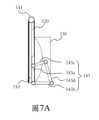
圖7A為一些實施例的成像切換裝置的卡扣結構為折疊時右側示意圖。FIG. 7A is a schematic diagram of the right side of the buckle structure of the imaging switching device of some embodiments when it is folded.
圖7B為一些實施例的成像切換裝置的卡扣結構為展開時右側示意圖。FIG. 7B is a schematic diagram of the right side of the buckle structure of the imaging switching device of some embodiments when it is unfolded.
圖7C為一些實施例的成像切換裝置與可撓性連接部件的示意圖。FIG. 7C is a schematic diagram of an imaging switching device and a flexible connecting component of some embodiments.
圖8為一些實施例的切換光學成像的處理系統的示意圖。FIG8 is a schematic diagram of a processing system for switching optical imaging in some embodiments.
圖9為一些實施例的切換光學成像的處理系統的投射訊號處理的示意圖。FIG9 is a schematic diagram of projection signal processing of a switching optical imaging processing system in some embodiments.
圖10為一些實施例的處理系統之運作流程示意圖。Figure 10 is a schematic diagram of the operation process of the processing system of some embodiments.
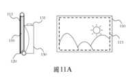
圖11A為一些實施例的顯示單元與顯示區域範圍示意圖。Figure 11A is a schematic diagram of the display unit and display area range of some embodiments.
圖11B為一些實施例的被遮蔽的顯示區域範圍示意圖。FIG. 11B is a schematic diagram of the scope of the masked display area in some embodiments.
圖12為一些實施例的另一切換光學成像的處理系統的示意圖。FIG12 is a schematic diagram of another processing system for switching optical imaging in some embodiments.
請參考圖1、圖2、圖3、圖4與圖5所示,分別為一些實施例的光學成像的切換裝置立體示意圖、成像切換裝置的展開與折疊的側視圖、第一光路的各段光線路徑示意圖。光學成像的切換裝置(以下簡稱為成像切換裝置100)包括顯示單元110、分光片120、凹面反射單元130與第一樞接部件141。Please refer to Figures 1, 2, 3, 4 and 5, which are three-dimensional schematic diagrams of optical imaging switching devices of some embodiments, side views of the unfolded and folded imaging switching devices, and schematic diagrams of the paths of each section of the first optical path. The optical imaging switching device (hereinafter referred to as the imaging switching device 100) includes a
顯示單元110具有第一顯示側邊111與第二顯示側邊112。顯示單元110可以是但不限定為液晶顯示器,也可以採用行動裝置的螢幕,或者其他種類的顯示器。顯示單元110運作時提供一顯示光源150。在圖2、圖3中為能表示顯示光源150的一側面,因此在顯示單元110的一側面以粗黑線段作為表示為顯示光源150的側面,並將此一側面稱為顯示面113。第一顯示側邊111與第二顯示側邊112為顯示面113的相對兩側邊。顯示單元110可以於原始位置(無標號)與投射位置(無標號)之間轉動,其轉動處理於後文另外說明。The
分光片120具有第一分光側邊121、第二分光側邊122與分光鏡面123。第一分光側邊121與第二分光側邊122為相對兩側邊。分光鏡面123設置於第一分光側邊121與第二分光側邊122之間且面對凹面反射單元130的側面。在圖2的分光片120中係以粗黑線表示分光鏡面123。第一樞接部件141樞接第一顯示側邊111與第一分光側邊121。顯示面113的顯示範圍小於或等於分光鏡面123的範圍。The
顯示單元110的第一顯示側邊111以第一樞接部件141為軸心轉動,顯示單元110的第二顯示側邊112可以在原始位置與投射位置之間轉動。為方便說明,成像切換裝置100於展開或折疊時顯示單元110的擺放狀態,因此將以顯示單元110位於原始位置或投射位置作為代稱。原始位置為成像切換裝置100折疊後顯示單元110位於分光片120的前方,如圖3所示。相對的,投射位置為成像切換裝置100展開後顯示單元110位於分光片120上方。顯示單元110於投射位置時,第二分光側邊122可以抵靠於凹面反射單元130。The
當顯示單元110位於原始位置,顯示面113的顯示光源150不會投射至分光鏡面123,如圖3所示。當顯示單元110位於投射位置時,顯示單元110將顯示光源150投射至分光鏡面123。分光鏡面123將部分反射的顯示光源150的光線至凹面反射單元130,此一光線稱為第一光線151a。圖4的黑色垂直箭頭線段係為顯示光源150的光線,圖4的黑色水平箭頭線段係為第一光線151a,垂直虛線線段為透射過分光片120的光線。When the
凹面反射單元130具有第一單元側邊131、第二單元側邊132與凹反射面133,第一單元側邊131與第二單元側邊132為相對兩側邊。凹反射面133設置於第一單元側邊131與第二單元側邊132之間。凹反射面133將第一光線151a反射至分光片120。當顯示單元110位於原始位置,凹反射面133正對於分光片120的分光鏡面123。凹面反射單元130、分光片120與顯示單元110三者相互平行,如圖3所示。The
在一些實施例中,凹反射面133的光軸與分光鏡面123的夾角為45度。分光片120的透射率與反射率是取決於鍍膜材質。在此為方便說明,在圖2、圖4、圖5中均以45度角作為分光片120的透射與反射的說明。顯示單元110與分光片120的夾角係為45度,且第二光線151b與分光片120的夾角也為45度。In some embodiments, the angle between the optical axis of the concave
當顯示單元110位於投射位置時,第二顯示側邊112位於凹面反射單元130的第一單元側邊131。第二顯示側邊112可以通過卡扣、磁力或其他固定結構被固定於第一單元側邊131。凹面反射單元130可以將第一光線151a反射至分光鏡面123,而凹面反射單元130反射至分光鏡面123的光線稱其為第二光線151b,請參考圖4中的黑色水平箭頭線段。凹面反射單元130用以放大顯示單元110的虛像成像範圍,而所形成的虛像後文均稱為虛擬圖像212。凹面反射單元130的放大倍率根據凹面曲率所決定。凹面反射單元130右側的虛線線段為虛像的成像像距,稱其為虛像像距211。When the
第二光線151b反射至分光鏡面123時,將會有部分的第二光線151b透射過分光鏡面123,而透射出的光線後稱為第三光線151c。使用者T可以通過分光片120與凹面反射單元130觀看第三光線151c與其相應的虛擬圖像212。而顯示光源150、第一光線151a、第二光線151b與第三光線151c所形成的光路集合即為第一光路151,請參考圖2所示。When the
顯示單元110位於投射位置,顯示單元110至使用者T之間的光路即為第一光路151。使用者T透過分光片120與凹面反射單元130可以觀看顯示單元110的放大後的虛擬圖像212。並且通過凹面反射單元130的反射後,虛擬圖像212也會呈現彎曲的視覺效果,請參考圖1所示。當顯示單元110位於原始位置時,顯示單元110的顯示光源150直接投射至使用者T,而此一光路為第二光路152。The
在一些實施例中,成像切換裝置100更具有第二樞接部件142,請參考圖6。第二樞接部件142樞接於第二分光側邊122與第二單元側邊132。分光片120以第二樞接部件142為軸心轉動,使得第一分光側邊121可以移離或移近第一單元側邊131。當顯示單元110轉動至投射位置時,第一分光側邊121移離第一單元側邊131,並且第一單元側邊131抵住第一顯示側邊111,如圖6中的下方所示。第一單元側邊131可以通過扣合、磁性定位或者套接等方式藉以固定於第一單元側邊131。於此同時,顯示單元110、分光片120與凹面反射單元130之間形成一投射空間(無標號),以供第一光線151a、第二光線151b的反射。In some embodiments, the
在一些實施例中,成像切換裝置100更具有卡扣結構143,如圖7A與圖7B所示。卡扣結構143具有兩第一固定臂143a、兩第二固定臂143b、兩第一延展臂143c與兩第二延展臂143d。在圖7A中係為卡扣結構的右側視圖。兩第一固定臂143a分別固定設置於分光片120的相對兩側邊。兩第二固定臂143b分別固定設置於凹面反射單元130的相對兩側邊。第一固定臂143a的一端樞接於第二固定臂143b的一端。第一延展臂143c的一端樞接於第一固定臂143a之中,第一延展臂143c的另一端樞接於第二延展臂143d的一端。第二延展臂143d的另一端樞接於第二固定臂143b的另一端。In some embodiments, the
當顯示單元110位於原始位置,第一延展臂143c與第二延展臂143d樞轉並收合,使得分光片120可以抵靠住凹面反射單元130,如圖7A所示。當顯示單元110位於投射位置,第一延展臂143c與第二延展臂143d的兩端分別樞轉並延伸展開,使得分光片120移離凹面反射單元130,如圖7B所示。When the
在一些實施例中,成像切換裝置100更具有可撓性連接部件144,如圖7C所示。可撓性連接部件144連接於第二分光側邊122與第二單元側邊132。當第二分光側邊122為軸心的轉動時,可撓性連接部件144提供分光片120與凹面反射單元130的連接,以供第一分光側邊121可以移離或移近第一單元側邊131。可撓性連接部件144可以是但不限定為軟性電路板,也可以是魔鬼沾、橡膠或彈性布料等。In some embodiments, the
在一些實施例中,切換光學成像的處理系統(簡稱為處理系統800)包括成像切換裝置100、顯示單元110與處理單元810,請參考圖8、圖9。處理單元810電性連接於顯示單元110與成像切換裝置100。顯示單元110提供顯示光源150至使用者T或成像切換裝置100,並形成第一光路151或第二光路152。顯示單元110的第一光路151與第二光路152可以參考前文所述。In some embodiments, the processing system for switching optical imaging (referred to as processing system 800) includes an
成像切換裝置100具有分光片120、凹面反射單元130、第一樞接部件141與感測單元161。凹面反射單元130、分光片120與第一樞接部件141的連接方式與作動可以參考前一實施態樣的說明。感測單元161配置於凹面反射單元130的第一單元側邊131。感測單元161用以偵測顯示單元110是否位於投射位置。當顯示單元110位於投射位置,顯示單元110靠抵並觸發感測單元161,使感測單元161產生投射訊號911。感測單元161傳送投射訊號911至處理單元810。感測單元161可以是按壓開關、磁簧開關或光敏電阻等方式實現。圖9中係以按壓開關為感測單元161為例,當顯示單元110抵靠於第一單元側邊121時,顯示單元110將會觸壓感測單元161,直至顯示單元110由投射位置轉至原始位置。The
處理單元810電性連接於顯示單元110與感測單元161。處理單元810根據投射訊號911輸出影像調整訊號820,並將影像輸出調整訊號發送至顯示單元110。顯示單元110根據影像調整訊號820調整自身的影像參數,藉以調整顯示單元110的播放影像的內容。The
為進一步說明處理系統800的整體運作,請配合參考圖10,其係為在一些實施例的處理系統之運作流程示意圖。To further illustrate the overall operation of the
步驟S910:由處理單元偵測顯示單元位於成像切換裝置的原始位置或投射位置,其中顯示單元的第一顯示側邊樞接於成像切換裝置,顯示單元以第一顯示側邊為軸心在原始位置與投射位置之間轉動;步驟S920:顯示單元位於原始位置,顯示單元投射顯示光源至使用者,用以形成第二光路;步驟S930:顯示單元由原始位置轉往至投射位置,處理單元調整顯示單元的影像參數;以及步驟S940:當顯示單元位於投射位置,顯示單元的顯示光源投射至成像切換裝置,於成像切換裝置的投射空間中形成第一光路。Step S910: The processing unit detects that the display unit is located at the original position or the projection position of the imaging switching device, wherein the first display side of the display unit is hinged to the imaging switching device, and the display unit rotates between the original position and the projection position with the first display side as the axis; Step S920: The display unit is located at the original position, and the display unit projects a display light source to the user to form a second light path; Step S930: The display unit rotates from the original position to the projection position, and the processing unit adjusts the image parameters of the display unit; and Step S940: When the display unit is located at the projection position, the display light source of the display unit is projected to the imaging switching device to form a first light path in the projection space of the imaging switching device.
首先,成像切換裝置100處於折疊的狀態,意即為顯示單元110位於原始位置。使用者T可以致能顯示單元110運作,並且顯示單元110將顯示光源150直接投射至使用者T並形成第二光路152,請參考圖3所示。將顯示單元110從原始位置轉動至投射位置,如圖2所示。當顯示單元110位於投射位置時投射顯示光源150,顯示單元110、分光片120與凹面反射單元130之間形成一個投射空間。顯示單元110投射顯示光源150至分光片120與凹面反射單元130。First, the
在一些實施例中,成像切換裝置100更具有第二樞接部件142。第二樞接部件142連接於第二分光側邊122與第二單元側邊132。當顯示單元110從原始位置轉動至投射位置時,分光片120也會以第二樞接部件142為軸心轉動,使得分光片120移離凹面反射單元130。此外,成像切換裝置100也可以以可撓性連接部件144分別連接第二分光側邊122與第二單元側邊132。In some embodiments, the
在一些實施例中,感測單元161可以設置於凹面反射單元130的第二單元側邊132(無繪示感測單元161)。當顯示單元110位於原始位置時,感測單元161將接觸於分光片120。當顯示單元110轉動至投射位置時,感測單元161可以被釋放並產生投射訊號911。反之,當顯示單元110由投射位置轉向至原始位置時,感測單元161輸出回復訊號912至處理單元810,使顯示單元110的亮度從投射亮度調整為初始亮度。In some embodiments, the
而影像參數包括顯示區域、顯示比例、區域亮度、影像對比度、影像銳利度或反轉影像。顯示區域意即為顯示單元110的可視範圍,請參考圖11A與圖11B所示。圖11A係為顯示單元110位於原始位置,圖11B係為顯示單元110位於投射位置。顯示單元110中的虛線框為顯示區域,可以將顯示區域視為顯示面113。The image parameters include display area, display ratio, area brightness, image contrast, image sharpness or inverted image. The display area means the visible range of the
當顯示單元110位於投射位置,第一單元側邊131遮蔽顯示區域的底部,如圖11B所示。因此處理單元810可以發送將可視範圍縮小的影像調整訊號820,使顯示單元110的可視範圍縮放至相應範圍。處理單元810可以根據凹面反射單元130的曲率調整顯示單元110的顯示區域的顯示比例。When the
除了顯示區域的調整外,由於人眼的雙眼可視視角的範圍大約為124度。所以會將放大後的虛擬圖像212需要是位於人眼的可視視角的範圍之中。對於凹面成像而言,物距與放大倍率係為反比。若以16:9的32吋的顯示單元110為例,顯示單元110的寬約為76cm、高約為45cm。分光片120至凹面反射單元130之間的物距約為22.5cm~30cm(其區間係為凹反射面133的曲率所決定)。而於此範圍的虛擬圖像212與使用者T的像距約為1m,並且虛擬圖像212的範圍也接近可視視角的最大值。但並不侷限於前述尺寸的顯示單元110,所述的實施態樣也可以應用在其他尺寸的顯示單元110中。In addition to the adjustment of the display area, since the human eye's binocular viewing angle range is approximately 124 degrees. Therefore, the enlarged
處理單元810根據分光片120的透射/反射亮度衰減的比例向顯示單元110發送調高亮度的影像調整訊號820。在此將顯示光源150的原始亮度稱為初始亮度,而調整後的顯示光源150的亮度為投射亮度。若分光片120的透射/反射後的亮度為50%。由於顯示光源150經過兩次反射與一次透射,分別是第一次反射為分光片120、第二次由凹面反射單元130反射、一次透射為分光片120。分光片120反射後使得顯示光源150的亮度下降50%,而凹面反射單元130反射第一光線151a不造成亮度下降,所以第三光線151c的亮度為顯示光源150的亮度25%。因此,處理單元810可以驅動顯示單元110將顯示光源150的亮度調整為400%,以使第三光線151c的亮度與原始位置的顯示光源150的亮度一致。換言之,顯示單元110轉動至於投射位置,處理單元810將顯示單元110的初始亮度調整為投影亮度,而投影亮度大於初始亮度。在一實施例中,處理單元810也可以同時調整影像對比度、銳利度,藉以凸顯虛擬圖像212的成像。The
在一些實施例中,切換光學成像的處理系統800包括顯示單元110、成像切換裝置100、處理單元810與計算機840,請參考圖12所示。顯示單元110、成像切換裝置100與處理單元810的所屬元件與連接方式可以參考前述實施態樣。計算機840電性連接於顯示單元110與處理單元810計算機840提供顯示單元110的數位圖像訊號,意即對應前述虛擬圖像212的影像訊號830。處理單元810根據感測單元161的投射訊號911或回復訊號912產生影像調整訊號820。處理單元810傳送影像調整訊號820至計算機840。計算機840根據影像調整訊號820調整數位圖像訊號的影像訊號830與所屬的影像參數。其中,影像參數包括顯示區域、顯示比例、區域亮度、影像對比度、影像銳利度或反轉影像。In some embodiments, the
所述的光學成像的切換裝置、處理系統800與方法可以應用在現有的顯示單元110上,除了實現全螢幕的影像放大,並且也滿足人眼視覺的遠處成像的目的。使用者T可以藉由成像切換裝置100觀看更大可視範圍的影像。由於放大後的影像並非是局部的放大,而是針對影像整體並實現影像景深與畫面彎曲,進而加強觀影時的沉浸感受。並且成像切換裝置100可以折疊並收納於顯示單元110的背板。The optical imaging switching device,
100:成像切換裝置100: Imaging switching device
110:顯示單元110: Display unit
113:顯示面113: Display surface
120:分光片120: Spectrometer
123:分光鏡面123: Spectroscopic mirror
130:凹面反射單元130: Concave reflection unit
133:凹反射面133: Concave reflective surface
141:第一樞接部件141: First joint component
150:顯示光源150: Display light source
151:第一光路151: First light path
151a:第一光線151a: First Light
151b:第二光線151b: Second ray
151c:第三光線151c: The third ray
211:虛像像距211: Virtual image distance
212:虛擬圖像212: Virtual image
T:使用者T: User
Claims (13)
Translated fromChinesePriority Applications (1)
| Application Number | Priority Date | Filing Date | Title |
|---|---|---|---|
| TW112116196ATWI857594B (en) | 2023-05-01 | 2023-05-01 | Switchable optical imaging device, processing system, and method, the optical imaging processing system |
Applications Claiming Priority (1)
| Application Number | Priority Date | Filing Date | Title |
|---|---|---|---|
| TW112116196ATWI857594B (en) | 2023-05-01 | 2023-05-01 | Switchable optical imaging device, processing system, and method, the optical imaging processing system |
Publications (2)
| Publication Number | Publication Date |
|---|---|
| TWI857594Btrue TWI857594B (en) | 2024-10-01 |
| TW202445204A TW202445204A (en) | 2024-11-16 |
Family
ID=94083705
Family Applications (1)
| Application Number | Title | Priority Date | Filing Date |
|---|---|---|---|
| TW112116196ATWI857594B (en) | 2023-05-01 | 2023-05-01 | Switchable optical imaging device, processing system, and method, the optical imaging processing system |
Country Status (1)
| Country | Link |
|---|---|
| TW (1) | TWI857594B (en) |
Citations (4)
| Publication number | Priority date | Publication date | Assignee | Title |
|---|---|---|---|---|
| US7414831B1 (en)* | 2004-04-01 | 2008-08-19 | Fergason Patent Properties, Llc | Adjustable display system |
| TW201732371A (en)* | 2016-01-22 | 2017-09-16 | 康寧公司 | Wide field personal display |
| CN108700751B (en)* | 2016-03-04 | 2020-11-24 | 夏普株式会社 | A head-mounted display that uses spatial light modulators to generate holographic images |
| US11143948B2 (en)* | 2006-09-29 | 2021-10-12 | Reald Inc. | Polarization conversion systems for stereoscopic projection |
- 2023
- 2023-05-01TWTW112116196Apatent/TWI857594B/enactive
Patent Citations (4)
| Publication number | Priority date | Publication date | Assignee | Title |
|---|---|---|---|---|
| US7414831B1 (en)* | 2004-04-01 | 2008-08-19 | Fergason Patent Properties, Llc | Adjustable display system |
| US11143948B2 (en)* | 2006-09-29 | 2021-10-12 | Reald Inc. | Polarization conversion systems for stereoscopic projection |
| TW201732371A (en)* | 2016-01-22 | 2017-09-16 | 康寧公司 | Wide field personal display |
| CN108700751B (en)* | 2016-03-04 | 2020-11-24 | 夏普株式会社 | A head-mounted display that uses spatial light modulators to generate holographic images |
Also Published As
| Publication number | Publication date |
|---|---|
| TW202445204A (en) | 2024-11-16 |
Similar Documents
| Publication | Publication Date | Title |
|---|---|---|
| US9983413B1 (en) | Display apparatus and method of displaying using context and focus image renderers and optical combiners | |
| US9989774B1 (en) | Display apparatus and method of displaying using optical combiners and context and focus image renderers | |
| JP3278521B2 (en) | Rear projection type image display | |
| US5905478A (en) | Twice folded compound magnified virtual image electronic display | |
| EP0883830A4 (en) | Desktop large image and eye-contact projection display | |
| CN114296226B (en) | Optical module, optical system and head-mounted display device | |
| JP3387487B2 (en) | Immersive sensation generator | |
| TWI857594B (en) | Switchable optical imaging device, processing system, and method, the optical imaging processing system | |
| US20220236564A1 (en) | Display panel with backreflection suppression comprising first and second birefringent layers and a reflectivity layer | |
| US20160094820A1 (en) | System for balancing the brightness of 2D and 3D cinema presentation | |
| JP3171955B2 (en) | Display imaging device | |
| KR100337606B1 (en) | Apparatus and method for generating the three dimensional image | |
| TW202235979A (en) | Display panel with backreflection suppression | |
| US10495895B2 (en) | Display apparatus and method of displaying using polarizers | |
| KR100317024B1 (en) | 3-Dimension Picture Displaying Apparatus with Polarizing Glasses | |
| JP2007004031A (en) | Projector apparatus | |
| CN219418280U (en) | Learning machine with projection function and display screen | |
| TWI892572B (en) | Screen magnifying display device | |
| CN108415215A (en) | Stereoprojection imaging device and stereoscopic image showing system | |
| KR101741912B1 (en) | Image magnifier | |
| CN211928311U (en) | Display optics and headsets | |
| CN217425840U (en) | Display device and electronic equipment with same | |
| JP7754328B2 (en) | Aerial image display system, display control device, display control method and program | |
| JP7726407B2 (en) | Aerial Image Display System | |
| JP4021267B2 (en) | Stereoscopic image projecting optical element and projector incorporating the same |