TWI855950B - Power supply protection method and system - Google Patents
Power supply protection method and systemDownload PDFInfo
- Publication number
- TWI855950B TWI855950BTW112151191ATW112151191ATWI855950BTW I855950 BTWI855950 BTW I855950BTW 112151191 ATW112151191 ATW 112151191ATW 112151191 ATW112151191 ATW 112151191ATW I855950 BTWI855950 BTW I855950B
- Authority
- TW
- Taiwan
- Prior art keywords
- power
- circuits
- power transmission
- preset
- control device
- Prior art date
Links
Images


Landscapes
- Direct Current Feeding And Distribution (AREA)
- Protection Of Static Devices (AREA)
Abstract
Description
Translated fromChinese本發明係關於一種電源保護方法及系統。The present invention relates to a power protection method and system.
隨著例如桌上型電腦或筆記型電腦等電子裝置的廣泛應用及技術的快速發展,電源供應裝置可視為電子裝置的核心元件。電源供應裝置的安全性及穩定性日益受到關注。With the widespread application of electronic devices such as desktop computers or laptops and the rapid development of technology, power supply devices can be regarded as the core components of electronic devices. The safety and stability of power supply devices are increasingly concerned.
然而,傳統的電源保護機制在面對例如過電壓或過電流的極端異常情況時,往往無法即時回應,導致電源供應裝置損壞、電子裝置當機等問題,進而影響了使用者的使用經驗以及資料安全。此外,傳統的電源保護機制在面臨異常情況時,通常採取直接切斷電源的方式,而這種簡單且直覺的方法可能導致資料遺失及裝置損壞,無法滿足現代對電子設備的電源供應裝置的高要求。However, traditional power protection mechanisms often fail to respond immediately to extreme abnormal conditions such as overvoltage or overcurrent, resulting in power supply device damage, electronic device crashes, and other problems, which in turn affects the user experience and data security. In addition, traditional power protection mechanisms usually directly cut off the power supply when faced with abnormal conditions. This simple and intuitive method may cause data loss and device damage, and cannot meet the high requirements of modern power supply devices for electronic equipment.
鑒於上述,本發明提供一種解決上述問題的電源保護方法及系統。In view of the above, the present invention provides a power protection method and system for solving the above problems.
依據本發明一實施例的電源保護方法,包括藉由控制裝置執行:取得多個電力傳輸電路的多個電力參數;當所述多個電力參數的一或多者大於各自對應的預設值時,關斷所述多個電力傳輸電路中的一或多個對應電路;以及計時所述一或多個對應電路被關斷的關斷時間,以於關斷時間等於或大於預設時間時,導通所述一或多個對應電路。According to an embodiment of the present invention, a power protection method includes executing, by a control device: obtaining multiple power parameters of multiple power transmission circuits; when one or more of the multiple power parameters are greater than their respective corresponding preset values, shutting down one or more corresponding circuits in the multiple power transmission circuits; and timing the shutdown time of the one or more corresponding circuits, so as to turn on the one or more corresponding circuits when the shutdown time is equal to or greater than the preset time.
依據本發明一實施例的電源保護系統包括:多個電力傳輸電路、電源偵測器以及控制裝置。所述多個電力傳輸電路用於接收及輸出電力。電源偵測器連接於所述多個電力傳輸電路,用於偵測所述多個電力傳輸電路的多個電力參數。控制裝置連接於所述多個電力傳輸電路及電源偵測器,控制裝置用於在所述多個電力參數的一或多者大於各自對應的預設值時,關斷所述多個電力傳輸電路中的一或多個對應電路,以及計時所述一或多個對應電路被關斷的關斷時間,以於關斷時間等於或大於預設時間時,導通所述一或多個對應電路。According to an embodiment of the present invention, a power protection system includes: a plurality of power transmission circuits, a power detector and a control device. The plurality of power transmission circuits are used to receive and output power. The power detector is connected to the plurality of power transmission circuits and is used to detect a plurality of power parameters of the plurality of power transmission circuits. The control device is connected to the plurality of power transmission circuits and the power detector, and the control device is used to shut down one or more corresponding circuits in the plurality of power transmission circuits when one or more of the plurality of power parameters is greater than their respective corresponding preset values, and to time the shutdown time of the one or more corresponding circuits, so as to turn on the one or more corresponding circuits when the shutdown time is equal to or greater than the preset time.
綜上所述,根據以上一或多個實施例的電源保護方法及系統可在電力傳輸電路面臨異常條件時使電力傳輸電路能夠迅速恢復電源裝置的正常工作狀態,以提高整體系統的穩定性、安全性及相容性。In summary, the power protection method and system according to one or more of the above embodiments can enable the power transmission circuit to quickly restore the normal working state of the power device when the power transmission circuit encounters abnormal conditions, so as to improve the stability, safety and compatibility of the overall system.
以上之關於本揭露內容之說明及以下之實施方式之說明係用以示範與解釋本發明之精神與原理,並且提供本發明之專利申請範圍更進一步之解釋。The above description of the disclosed content and the following description of the implementation methods are used to demonstrate and explain the spirit and principle of the present invention, and provide a further explanation of the scope of the patent application of the present invention.
以下在實施方式中詳細敘述本發明之詳細特徵以及優點,其內容足以使任何熟習相關技藝者了解本發明之技術內容並據以實施,且根據本說明書所揭露之內容、申請專利範圍及圖式,任何熟習相關技藝者可輕易地理解本發明相關之目的及優點。以下之實施例係進一步詳細說明本發明之觀點,但非以任何觀點限制本發明之範疇。The detailed features and advantages of the present invention are described in detail in the following embodiments, and the contents are sufficient to enable any person skilled in the relevant art to understand the technical contents of the present invention and implement them accordingly. Moreover, according to the contents disclosed in this specification, the scope of the patent application and the drawings, any person skilled in the relevant art can easily understand the relevant purposes and advantages of the present invention. The following embodiments are to further illustrate the viewpoints of the present invention, but are not to limit the scope of the present invention by any viewpoint.
依據以下一或多個實施例描述的方法及系統可用於保護電源供應裝置中的電力傳輸電路。為了更詳細說明保護方式,請先參考圖1,其中圖1係依據本發明一實施例所繪示的電源保護系統的方塊圖。如圖1所示,電源保護系統1包括第一電力傳輸電路11、第二電力傳輸電路12、電源偵測器13以及控制裝置14。第一電力傳輸電路11及第二電力傳輸電路12連接於電源A1。電源偵測器13連接於第一電力傳輸電路11的輸入端的線路及輸出端的線路,以及第二電力傳輸電路12的輸入端的線路及輸出端的線路。控制裝置14連接於第一電力傳輸電路11、第二電力傳輸電路12以及電源偵測器13。The method and system described in accordance with one or more of the following embodiments can be used to protect the power transmission circuit in the power supply device. In order to explain the protection method in more detail, please refer to FIG. 1, wherein FIG. 1 is a block diagram of a power protection system according to an embodiment of the present invention. As shown in FIG. 1, the
第一電力傳輸電路11及第二電力傳輸電路12用於接收來自電源A1的電力,及據以輸出電力至所連接的電子裝置。電源A1可以是市電。舉例而言,電子裝置可為桌上型電腦或筆記型電腦。進一步而言,電子裝置可為顯卡,本發明不對電子裝置的類型與以限制。第一電力傳輸電路11及第二電力傳輸電路12可為用於將電源A1提供的電力轉為供應予電子裝置的電源供應裝置中的電力元件。舉例而言,第一電力傳輸電路11及第二電力傳輸電路12可各自包含電容器、金屬氧化物半導體場效電晶體及功率因數修正(power factor correction,PFC)電路中的一或多者。所述電容器可為超級電容器。另需說明的是,圖1示例性示出兩個電力傳輸電路,但電源保護系統1可包括兩個以上的電力傳輸電路,本發明不予以限制。The first
電源偵測器13用於偵測第一電力傳輸電路11及第二電力傳輸電路12各自從電源A1接收的輸入電力及輸出至電子裝置的輸出電力,以得到對應的電力參數。電源偵測器13可包括電壓感測器及電流感測器的至少一者,電力參數可為電壓值或電流值。The
控制裝置14用於從電源偵測器13接收電力偵測結果,及根據電源偵測器13的電力偵測結果關斷或導通第一電力傳輸電路11及第二電力傳輸電路12。控制裝置14可包括一或多個處理器,所述處理器例如為中央處理器、繪圖處理器、微控制器、可程式化邏輯控制器或其他具有訊號處理功能的處理器。The
請一併參考圖1及圖2,其中圖2係依據本發明一實施例所繪示的電源保護方法的流程圖。如圖2所示,電源保護方法包括:步驟S101:取得多個電力傳輸電路的多個電力參數;步驟S103:判斷所述多個電力參數是否大於各自對應的預設值;當步驟S103的判斷結果為「否」時,再次執行步驟S101;當步驟S103的判斷結果為「是」時,執行步驟S105:關斷所述多個電力傳輸電路中的一或多個對應電路;步驟S107:計時所述一或多個對應電路被關斷的關斷時間;步驟S109:判斷關斷時間是否等於或大於預設時間;當步驟S109的判斷結果為「否」時,執行步驟S107;以及當步驟S109的判斷結果為「是」時,執行步驟S111:導通所述一或多個對應電路。Please refer to FIG. 1 and FIG. 2, wherein FIG. 2 is a flow chart of a power protection method according to an embodiment of the present invention. As shown in FIG. 2, the power protection method includes: step S101: obtaining multiple power parameters of multiple power transmission circuits; step S103: determining whether the multiple power parameters are greater than the corresponding preset values; when the determination result of step S103 is "no", executing step S101 again; when the determination result of step S103 is "yes", executing step S105: shutting down the multiple power transmission circuits; one or more corresponding circuits in the transmission circuit; step S107: timing the off time when the one or more corresponding circuits are turned off; step S109: judging whether the off time is equal to or greater than a preset time; when the judgment result of step S109 is "no", executing step S107; and when the judgment result of step S109 is "yes", executing step S111: turning on the one or more corresponding circuits.
於步驟S101,控制裝置14從電源偵測器13取得第一電力傳輸電路11的電力參數及第二電力傳輸電路12的電力參數。如前所述,電力參數可為第一電力傳輸電路11及第二電力傳輸電路12各自的輸入電力及輸出電力的電壓值或電流值。In step S101, the
於步驟S103,控制裝置14判斷第一電力傳輸電路11及第二電力傳輸電路12的每一者的電力參數是否大於各自對應的預設值。舉例而言,當電力傳輸電路為電容器時,預設值可為11.4伏特或12伏特,其他電力傳輸電路的預設值亦可為11.4伏特或12伏特,且預設值可不大於13.5伏特,但本發明不予以限制。In step S103, the
當控制裝置14判斷第一電力傳輸電路11的電力參數不大於對應的預設值,且第二電力傳輸電路12的電力參數不大於對應的預設值時,表示第一電力傳輸電路11及第二電力傳輸電路12的輸入電力及輸出電力都落於正常範圍。因此,控制裝置14可再次執行步驟S101,以繼續對第一電力傳輸電路11及第二電力傳輸電路12進行監測。When the
當控制裝置14判斷第一電力傳輸電路11及第二電力傳輸電路12中的一或多者的電力參數大於對應的預設值,表示具有大於對應預設值之電力參數的電力傳輸電路(後稱對應電路)的輸入電力及/或輸出電力落於正常範圍外。因此,控制裝置14執行步驟S105,以關斷電力參數大於對應的預設值的一或多個對應電路。舉例而言,控制裝置14可關斷對應電路的輸入端的開關元件及關斷對應電路的輸出端的開關元件,其中開關元件可包括繼電器或電晶體,本發明不予以限制。為便於說明,以下假設第一電力傳輸電路11為對應電路(即電力參數大於預設值的電力傳輸電路),第二電力傳輸電路12非為對應電路(即電力參數不大於預設值的電力傳輸電路)。When the
於步驟S107,控制裝置14計時第一電力傳輸電路11的關斷時間。進一步而言,控制裝置14在關斷第一電力傳輸電路11後開始計時,以取得對應第一電力傳輸電路11的關斷時間。In step S107, the
於步驟S109,控制裝置14判斷關斷時間是否等於或大於預設時間。預設時間可為使第一電力傳輸電路11的電力參數降低至預設值的時間,及/或使第一電力傳輸電路11的溫度值降低至預設溫度的時間。預設時間例如為20毫秒,但本發明不予以限制。In step S109, the
當控制裝置14判斷關斷時間小於預設時間時,控制裝置14可再次執行步驟S107,即繼續計時關斷時間。當控制裝置14判斷關斷時間等於或大於預設時間時,控制裝置14導通第一電力傳輸電路11。換言之,當關斷時間等於或大於預設時間時,表示第一電力傳輸電路11的電力參數可能已經降低至預設值,及/或第一電力傳輸電路11的溫度值降低至預設溫度。因此,控制裝置14導通第一電力傳輸電路11,以使第一電力傳輸電路11可再次從電源A1接收電力,及輸出電力至電子裝置。When the
據此,根據以上一或多個實施例的電源保護方法及系統可在電力傳輸電路面臨異常條件時使電力傳輸電路能夠迅速恢復電源供應裝置的正常工作狀態,以提高整體系統的穩定性、安全性及相容性。Accordingly, the power protection method and system according to one or more of the above embodiments can enable the power transmission circuit to quickly restore the normal working state of the power supply device when the power transmission circuit faces abnormal conditions, so as to improve the stability, safety and compatibility of the overall system.
請一併參考圖1及圖3,其中圖3係依據本發明一實施例所繪示的維持電力傳輸電路的輸出電壓的流程圖。圖3所示的步驟S203可執行在圖2之步驟S103的判斷結果為「是」之後及步驟S105之前。如圖3所示,維持電力傳輸電路的輸出電壓包括:步驟S201:判斷電力參數大於預設值;步驟S203:判斷導通電路的輸出電壓是否不小於預設電壓;當步驟S203的判斷結果為「是」時,執行步驟S205:計時對應電路被關斷的關斷時間;以及當步驟S203的判斷結果為「否」時,執行步驟S207:輸出警告通知。步驟S201可視為圖2之步驟S103的判斷結果為「是」的情況,步驟S205可與圖2的步驟S107相同,故以下不再贅述步驟S201及步驟S205的內容。Please refer to FIG. 1 and FIG. 3 , wherein FIG. 3 is a flowchart of maintaining the output voltage of the power transmission circuit according to an embodiment of the present invention. Step S203 shown in FIG. 3 can be executed after the judgment result of step S103 in FIG. 2 is "yes" and before step S105. As shown in FIG. 3 , maintaining the output voltage of the power transmission circuit includes: step S201: determining whether the power parameter is greater than a preset value; step S203: determining whether the output voltage of the conductive circuit is not less than a preset voltage; when the determination result of step S203 is “yes”, executing step S205: timing the shutdown time of the corresponding circuit being shut down; and when the determination result of step S203 is “no”, executing step S207: outputting a warning notification. Step S201 can be regarded as the case where the judgment result of step S103 in FIG. 2 is "yes", and step S205 can be the same as step S107 in FIG. 2, so the contents of step S201 and step S205 will not be described in detail below.
於步驟S203,控制裝置14判斷所述多個電力傳輸電路中除了所述一或多個對應電路外的一或多個導通電路的輸出電壓的總和是否不小於預設電壓。預設電壓可為維持電子裝置運作時所需的最小電壓。導通電路為電力傳輸電路中電力參數不大於對應的預設值的一或多個電力傳輸電路。舉例而言,預設電壓可為11.4伏特,但本發明不予以限制。以上述第一電力傳輸電路11為對應電路為例,第二電力傳輸電路12為導通電路。In step S203, the
當控制裝置14判斷第二電力傳輸電路12的輸出電壓不小於預設電壓時,表示第二電力傳輸電路12輸出的輸出電壓足夠供電子裝置運作。因此,控制裝置14可計時第一電力傳輸電路11的關斷時間,即執行圖2的步驟S107。When the
反之,當控制裝置14判斷第二電力傳輸電路12的輸出電壓小於預設電壓時,表示第二電力傳輸電路12輸出的輸出電壓不足以供電子裝置運作。因此,於步驟S207,控制裝置14可輸出警告通知至所連接之顯示器及/或雲端等,以通知使用者電力不足的狀況。On the contrary, when the
透過圖3之實施例,可確保在關斷電源供應裝置中的一或多個電力傳輸電路時,不會因而造成電子裝置的運作中斷。Through the embodiment of FIG. 3 , it can be ensured that when one or more power transmission circuits in the power supply device are turned off, the operation of the electronic device will not be interrupted.
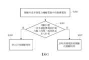
請一併參考圖1及圖4,其中圖4係依據本發明一實施例所繪示的在重啟過程中對電力傳輸電路的即時監測的流程圖。如圖4所示,在重啟過程中執行的即時監測包括:步驟S301:關斷所述電力傳輸電路中的所述一或多個對應電路;步驟S303:判斷對應所述一或多個對應電路的電力輸入的電力感測值是否大於零;當步驟S303的判斷結果為「是」時,執行步驟S305:停止計時關斷時間;以及當步驟S303的判斷結果為「否」時,執行步驟S307:計時對應電路被關斷的關斷時間。步驟S301可與圖2的步驟S105相同,步驟S307可與圖2的步驟S107相同,故不於此贅述。Please refer to FIG. 1 and FIG. 4 , wherein FIG. 4 is a flow chart of real-time monitoring of a power transmission circuit during a restart process according to an embodiment of the present invention. As shown in FIG. 4 , the real-time monitoring performed during the restart process includes: step S301: shutting down the one or more corresponding circuits in the power transmission circuit; step S303: determining whether the power sensing value of the power input corresponding to the one or more corresponding circuits is greater than zero; when the determination result of step S303 is “yes”, executing step S305: stopping the timing of the shutdown time; and when the determination result of step S303 is “no”, executing step S307: timing the shutdown time when the corresponding circuit is shut down. Step S301 may be the same as step S105 in FIG. 2 , and step S307 may be the same as step S107 in FIG. 2 , and thus will not be described in detail herein.
於步驟S303,控制裝置14可接收電源偵測器13對第一電力傳輸電路11(對應電路)的輸出端的感測結果,以判斷的第一電力傳輸電路11的電力感測值是否大於零。In step S303, the
當第一電力傳輸電路11的電力感測值大於零時,表示即使在關斷後,仍有電力從第一電力傳輸電路11流出。因此,於步驟S305,控制裝置停止計時關斷時間,以終止重啟程序。When the power sensing value of the first
當第一電力傳輸電路11的電力感測值不大於零(即等於零)時,表示無電力從關斷後的第一電力傳輸電路11流出。因此,控制裝置14可執行步驟S307,以繼續計時關斷時間。When the power sensing value of the first
透過圖4的實施例,可確保在執行重啟程序的過程中可避免持續性的電力輸入/輸出,而對電力傳輸電路造成更嚴重的傷害。Through the embodiment of FIG. 4 , it is ensured that continuous power input/output can be avoided during the restart process, thereby preventing the power transmission circuit from being more seriously damaged.
請一併參考圖1及圖5,其中圖5係依據本發明一實施例所繪示的針對電力傳輸線路的多次重啟的保護機制。需先說明的是,在圖5的實施例中,關斷對應電路可以是執行於所述一或多個對應電路的電力參數大於各自對應的預設值的持續時間落於暫態時間範圍內時,且此述的電力參數可以是指對應電路的輸出端的電力參數,其中暫態時間範圍例如為1毫秒,但本發明不予以限制。換言之,控制裝置14可以是在對應電路的輸出端的電力參數指示有突波的狀況時,關斷對應電路。Please refer to FIG. 1 and FIG. 5 , wherein FIG. 5 is a protection mechanism for multiple restarts of a power transmission line according to an embodiment of the present invention. It should be noted that in the embodiment of FIG. 5 , shutting down the corresponding circuit may be performed when the duration of the power parameter of the one or more corresponding circuits being greater than the corresponding preset value falls within the transient time range, and the power parameter mentioned here may refer to the power parameter of the output end of the corresponding circuit, wherein the transient time range is, for example, 1 millisecond, but the present invention is not limited thereto. In other words, the
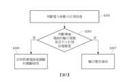
如圖5所示,保護機制可包括:步驟S401:關斷所述電力傳輸電路中的所述一或多個對應電路;步驟S403:計數關斷次數;步驟S405:判斷關斷次數是否不小於預設次數;當步驟S405的判斷結果為「是」時,執行步驟S407:關斷電力傳輸電路與電源之間的連接;以及當步驟S405的判斷結果為「否」時,執行步驟S409:取得電力傳輸電路的電力參數。步驟S401可與圖2的步驟S105相同,步驟S409可與圖2的步驟S101相同,故不於此贅述。As shown in FIG5 , the protection mechanism may include: step S401: shutting down the one or more corresponding circuits in the power transmission circuit; step S403: counting the number of shut-downs; step S405: determining whether the number of shut-downs is not less than a preset number; when the determination result of step S405 is “yes”, executing step S407: shutting down the connection between the power transmission circuit and the power source; and when the determination result of step S405 is “no”, executing step S409: obtaining the power parameters of the power transmission circuit. Step S401 may be the same as step S105 in FIG. 2 , and step S409 may be the same as step S101 in FIG. 2 , and thus will not be described in detail herein.
在關斷第一電力傳輸電路11後,於步驟S403,控制裝置14於關斷次數加1。具體而言,關斷次數的初始值可為0,且控制裝置14可每經過預設時段便歸零關斷次數,其中所述預設時段可為10分鐘、1小時或一天等,本發明不予以限制。換言之,用於執行步驟S405的關斷次數可為在預設時段中累計的關斷次數。並且,控制裝置14可於判斷第一電力傳輸電路11及第二電力傳輸電路12中的至少一者的電力參數大於預設值時,便於關斷次數加1。After the first
於步驟S405,控制裝置14判斷關斷次數是否不小於預設次數,其中預設次數例如為5次,但本發明不予以限制。當控制裝置14判斷關斷次數不小於預設次數時,表示經過多次重啟操作後,第一電力傳輸電路11可能已損壞,而導致第一電力傳輸電路11的電力參數經過多次重啟後仍不穩定。因此,於步驟S407,控制裝置14關斷電源A1與第一電力傳輸電路11以及第二電力傳輸電路12之間的連接。換言之,控制裝置14關斷電源A1與所有電力傳輸電路之間的連接,以確保電子裝置不會因電源供應裝置的問題而受損。In step S405, the
當控制裝置14判斷關斷次數小於預設次數時,控制裝置14可繼續監控第一電力傳輸電路11以及第二電力傳輸電路12的電力參數,即再次執行圖1的步驟S101。When the
綜上所述,根據以上一或多個實施例的電源保護方法及系統可在電力傳輸電路面臨異常條件時使電力傳輸電路能夠迅速恢復電源供應裝置的正常工作狀態,以提高整體系統的穩定性、安全性及相容性。透過維持電力傳輸電路的輸出電壓的機制,可確保在關斷電源供應裝置中的一或多個電力傳輸電路時,不會因而造成電子裝置的運作中斷。透過在重啟過程中對電力傳輸電路進行即時監測的機制,可確保在執行重啟程序的過程中可避免持續性的電力輸入/輸出,而對電力傳輸電路造成更嚴重的傷害。並且,透過在關斷次數過高而直接切斷電力傳輸電路與電源之間的連接的機制,可確保電子裝置不會因電源供應裝置問題而受損。In summary, the power protection method and system according to one or more of the above embodiments can enable the power transmission circuit to quickly restore the normal working state of the power supply device when the power transmission circuit faces abnormal conditions, so as to improve the stability, safety and compatibility of the overall system. By maintaining the output voltage of the power transmission circuit, it can be ensured that when one or more power transmission circuits in the power supply device are turned off, the operation of the electronic device will not be interrupted. By monitoring the power transmission circuit in real time during the restart process, it can be ensured that continuous power input/output can be avoided during the execution of the restart procedure, which can cause more serious damage to the power transmission circuit. Furthermore, by directly cutting off the connection between the power transmission circuit and the power source when the shutdown times are too high, it can be ensured that the electronic device will not be damaged due to problems with the power supply device.
雖然本發明以前述之實施例揭露如上,然其並非用以限定本發明。在不脫離本發明之精神和範圍內,所為之更動與潤飾,均屬本發明之專利保護範圍。關於本發明所界定之保護範圍請參考所附之申請專利範圍。Although the present invention is disclosed as above with the aforementioned embodiments, it is not intended to limit the present invention. Any changes and modifications made within the spirit and scope of the present invention are within the scope of patent protection of the present invention. Please refer to the attached patent application for the scope of protection defined by the present invention.
1:電源保護系統 11:第一電力傳輸電路 12:第二電力傳輸電路 13:電源偵測器 14:控制裝置 A1:電源 S101,S103,S105,S107,S109,S111,S201,S203,S205,S207,S301,S303,S305,S307,S401,S403,S405,S407,S409:步驟1: Power protection system11: First power transmission circuit12: Second power transmission circuit13: Power detector14: Control deviceA1: Power supplyS101, S103, S105, S107, S109, S111, S201, S203, S205, S207, S301, S303, S305, S307, S401, S403, S405, S407, S409: Steps
圖1係依據本發明一實施例所繪示的電源保護系統的方塊圖。 圖2係依據本發明一實施例所繪示的電源保護方法的流程圖。 圖3係依據本發明一實施例所繪示的維持電力傳輸電路的輸出電壓的流程圖。 圖4係依據本發明一實施例所繪示的在重啟過程中對電力傳輸電路的即時監測的流程圖。 圖5係依據本發明一實施例所繪示的針對電力傳輸線路的多次重啟的保護機制。FIG. 1 is a block diagram of a power protection system according to an embodiment of the present invention.FIG. 2 is a flow chart of a power protection method according to an embodiment of the present invention.FIG. 3 is a flow chart of maintaining the output voltage of a power transmission circuit according to an embodiment of the present invention.FIG. 4 is a flow chart of real-time monitoring of a power transmission circuit during a restart process according to an embodiment of the present invention.FIG. 5 is a protection mechanism for multiple restarts of a power transmission line according to an embodiment of the present invention.
S101,S103,S105,S107,S109,S111:步驟S101, S103, S105, S107, S109, S111: Steps
Claims (11)
Translated fromChinesePriority Applications (1)
| Application Number | Priority Date | Filing Date | Title |
|---|---|---|---|
| TW112151191ATWI855950B (en) | 2023-12-28 | 2023-12-28 | Power supply protection method and system |
Applications Claiming Priority (1)
| Application Number | Priority Date | Filing Date | Title |
|---|---|---|---|
| TW112151191ATWI855950B (en) | 2023-12-28 | 2023-12-28 | Power supply protection method and system |
Publications (2)
| Publication Number | Publication Date |
|---|---|
| TWI855950Btrue TWI855950B (en) | 2024-09-11 |
| TW202527413A TW202527413A (en) | 2025-07-01 |
Family
ID=93649300
Family Applications (1)
| Application Number | Title | Priority Date | Filing Date |
|---|---|---|---|
| TW112151191ATWI855950B (en) | 2023-12-28 | 2023-12-28 | Power supply protection method and system |
Country Status (1)
| Country | Link |
|---|---|
| TW (1) | TWI855950B (en) |
Citations (6)
| Publication number | Priority date | Publication date | Assignee | Title |
|---|---|---|---|---|
| CN105006895A (en)* | 2008-10-03 | 2015-10-28 | 捷通国际有限公司 | Power system |
| TWM562397U (en)* | 2018-02-22 | 2018-06-21 | Taipull Electric Co Ltd | Electric meter with wireless sensing pre-payment function |
| US20190052127A1 (en)* | 2017-08-11 | 2019-02-14 | Ningbo Weie Electronics Technology Ltd. | Wireless power transmission system, power transmitting terminal, power receiving terminal and detection method |
| TW201921796A (en)* | 2012-12-28 | 2019-06-01 | 日商半導體能源研究所股份有限公司 | Power storage device and power storage system |
| CN112668470A (en)* | 2017-03-23 | 2021-04-16 | 傲迪司威生物识别公司 | Cover for providing power to an electronic device |
| CN116095527A (en)* | 2021-11-05 | 2023-05-09 | 罗克韦尔自动化技术公司 | Configurable media interface module |
- 2023
- 2023-12-28TWTW112151191Apatent/TWI855950B/enactive
Patent Citations (6)
| Publication number | Priority date | Publication date | Assignee | Title |
|---|---|---|---|---|
| CN105006895A (en)* | 2008-10-03 | 2015-10-28 | 捷通国际有限公司 | Power system |
| TW201921796A (en)* | 2012-12-28 | 2019-06-01 | 日商半導體能源研究所股份有限公司 | Power storage device and power storage system |
| CN112668470A (en)* | 2017-03-23 | 2021-04-16 | 傲迪司威生物识别公司 | Cover for providing power to an electronic device |
| US20190052127A1 (en)* | 2017-08-11 | 2019-02-14 | Ningbo Weie Electronics Technology Ltd. | Wireless power transmission system, power transmitting terminal, power receiving terminal and detection method |
| TWM562397U (en)* | 2018-02-22 | 2018-06-21 | Taipull Electric Co Ltd | Electric meter with wireless sensing pre-payment function |
| CN116095527A (en)* | 2021-11-05 | 2023-05-09 | 罗克韦尔自动化技术公司 | Configurable media interface module |
Also Published As
| Publication number | Publication date |
|---|---|
| TW202527413A (en) | 2025-07-01 |
Similar Documents
| Publication | Publication Date | Title |
|---|---|---|
| CN104461809B (en) | A kind of fault information managing method and system | |
| TWI670952B (en) | Network switching system | |
| CN111475288A (en) | Server and power supply protection system thereof | |
| CN113315124B (en) | A method, system, computer device and storage medium for generating a stability control strategy | |
| US9722414B2 (en) | Power distribution and information handling | |
| CN111857308B (en) | Server power management method and system | |
| WO2024164620A1 (en) | Power supply failure detection circuit, method, system, electronic device, and non-volatile readable storage medium | |
| CN103176581B (en) | Power management device and power management method | |
| CN115543679B (en) | Liquid leakage detection line detection method, system, device, server and electronic equipment | |
| US20160156170A1 (en) | Server with power source protection system and power source protection method | |
| TWI855950B (en) | Power supply protection method and system | |
| CN115795568A (en) | Liquid cooling server liquid leakage protection method, device, equipment and storage medium | |
| CN107506281A (en) | A kind of multiple power supplies monitoring system and method | |
| CN114884021B (en) | Power supply control method of power supply circuit and related components | |
| CN111475292A (en) | Server system and frequency control device of processor in server system | |
| CN111190468A (en) | OPC interface heat dissipation device and method | |
| CN102810840B (en) | Voltage protection system | |
| CN114326990B (en) | Fan abnormality handling method, device, electronic equipment and storage medium | |
| CN120237604A (en) | Power supply protection method and system | |
| CN115473200A (en) | Overheat protection method and device for elevator control system, frequency converter and medium | |
| CN107179911A (en) | A kind of method and apparatus for restarting management engine | |
| CN111414066A (en) | A server expansion system and power control method thereof | |
| CN102983558B (en) | Circuit protection device and circuit protection method | |
| TWM556046U (en) | Network switching control system | |
| TW202040313A (en) | Server power managing method and system thereof |