TWI854504B - System of sensing concentration - Google Patents
System of sensing concentrationDownload PDFInfo
- Publication number
- TWI854504B TWI854504BTW112106522ATW112106522ATWI854504BTW I854504 BTWI854504 BTW I854504BTW 112106522 ATW112106522 ATW 112106522ATW 112106522 ATW112106522 ATW 112106522ATW I854504 BTWI854504 BTW I854504B
- Authority
- TW
- Taiwan
- Prior art keywords
- light
- sensing system
- concentration sensing
- rotating device
- polarization
- Prior art date
Links
- 238000012545processingMethods0.000claimsabstractdescription35
- 230000010287polarizationEffects0.000claimsdescription76
- 239000011159matrix materialSubstances0.000claimsdescription24
- 230000008859changeEffects0.000claimsdescription2
- 230000000149penetrating effectEffects0.000claimsdescription2
- 230000003287optical effectEffects0.000description13
- 239000008280bloodSubstances0.000description12
- 210000004369bloodAnatomy0.000description12
- 238000010586diagramMethods0.000description9
- 238000000034methodMethods0.000description8
- WQZGKKKJIJFFOK-GASJEMHNSA-NGlucoseNatural productsOC[C@H]1OC(O)[C@H](O)[C@@H](O)[C@@H]1OWQZGKKKJIJFFOK-GASJEMHNSA-N0.000description7
- 239000008103glucoseSubstances0.000description7
- 238000005259measurementMethods0.000description5
- 101000827703Homo sapiens Polyphosphoinositide phosphataseProteins0.000description4
- 102100023591Polyphosphoinositide phosphataseHuman genes0.000description4
- 238000013461designMethods0.000description4
- 230000005684electric fieldEffects0.000description4
- 101001121408Homo sapiens L-amino-acid oxidaseProteins0.000description3
- 102100026388L-amino-acid oxidaseHuman genes0.000description3
- 206010012601diabetes mellitusDiseases0.000description3
- 101100012902Saccharomyces cerevisiae (strain ATCC 204508 / S288c) FIG2 geneProteins0.000description2
- 238000001514detection methodMethods0.000description2
- 238000004519manufacturing processMethods0.000description2
- 238000012360testing methodMethods0.000description2
- 208000001072type 2 diabetes mellitusDiseases0.000description2
- 208000017667Chronic DiseaseDiseases0.000description1
- 206010073753Fear of injectionDiseases0.000description1
- 208000008589ObesityDiseases0.000description1
- 206010052428WoundDiseases0.000description1
- 208000027418Wounds and injuryDiseases0.000description1
- 230000032683agingEffects0.000description1
- WQZGKKKJIJFFOK-VFUOTHLCSA-Nbeta-D-glucoseChemical compoundOC[C@H]1O[C@@H](O)[C@H](O)[C@@H](O)[C@@H]1OWQZGKKKJIJFFOK-VFUOTHLCSA-N0.000description1
- 230000005540biological transmissionEffects0.000description1
- 238000010241blood samplingMethods0.000description1
- 239000008367deionised waterSubstances0.000description1
- 229910021641deionized waterInorganic materials0.000description1
- 230000002999depolarising effectEffects0.000description1
- 230000000694effectsEffects0.000description1
- 230000005670electromagnetic radiationEffects0.000description1
- 238000001914filtrationMethods0.000description1
- 239000012530fluidSubstances0.000description1
- 230000005182global healthEffects0.000description1
- 208000015181infectious diseaseDiseases0.000description1
- 150000002632lipidsChemical class0.000description1
- 239000004973liquid crystal related substanceSubstances0.000description1
- 238000012986modificationMethods0.000description1
- 230000004048modificationEffects0.000description1
- 235000020824obesityNutrition0.000description1
- 239000002245particleSubstances0.000description1
- 230000037081physical activityEffects0.000description1
- 239000000843powderSubstances0.000description1
- 230000002265preventionEffects0.000description1
- 239000007787solidSubstances0.000description1
- 238000001228spectrumMethods0.000description1
- 239000000126substanceSubstances0.000description1
- XLYOFNOQVPJJNP-UHFFFAOYSA-NwaterChemical compoundOXLYOFNOQVPJJNP-UHFFFAOYSA-N0.000description1
Images


Landscapes
- Investigating Or Analysing Materials By Optical Means (AREA)
Abstract
Description
Translated fromChinese本揭露是有關於一種濃度感測系統,且特別是有關於一種非侵入式的濃度感測系統。The present disclosure relates to a concentration sensing system, and more particularly to a non-invasive concentration sensing system.
糖尿病是一種常見的慢性疾病,對當代文明社會造成了巨大的影響,其中更以2型糖尿病對全球的健康性問題影響甚鉅。綜觀來看,導致2型糖尿病流行於全球的主要因素包括人口年齡老化、肥胖人口增加、以及體力活動減少等等。截至2021年為止,全球罹患糖尿病的病患已突破5億人口,預估2045年更將增加至7億人口。因此,糖尿病的檢測以及預防在現代已成為人類社會的重大議題。Diabetes is a common chronic disease that has had a huge impact on contemporary civilized society, and type 2 diabetes has had a particularly significant impact on global health issues. Overall, the main factors leading to the prevalence of type 2 diabetes worldwide include aging population, increasing obesity, and reduced physical activity. As of 2021, the number of patients with diabetes worldwide has exceeded 500 million, and it is estimated that the number will increase to 700 million by 2045. Therefore, the detection and prevention of diabetes has become a major issue in modern human society.
市面上的血糖機大多為侵入式的設計,意即檢測者須將採血針刺入體內採血才可檢測血糖。然而,人們對於針頭的恐懼心理、感染針頭對檢測者的風險、丟棄針頭對他人造成感染的可能性等等,都促使研究者近年來逐漸朝非侵入式的血糖檢測設計進行研究。Most blood glucose meters on the market are invasive in design, which means that the tester must insert a blood sampling needle into the body to draw blood before the blood glucose test can be performed. However, people's fear of needles, the risk of infected needles to the tester, and the possibility of discarding needles and causing infection to others have prompted researchers to gradually study non-invasive blood glucose test designs in recent years.
因此,亟需一種非侵入式的感測裝置,能重複且準確地感測血糖濃度的同時又不會對人體造成傷口,以減輕檢測者使用上的心理壓力。Therefore, there is an urgent need for a non-invasive sensing device that can repeatedly and accurately sense blood sugar concentration without causing any wounds to the human body, so as to reduce the psychological pressure on the tester.
因此,本揭露之實施例之一目的是在於提供一種濃度感測系統,其包含單個旋轉裝置,可使光線的光強度在經過旋轉裝置後變成旋轉裝置之旋轉角頻率的函數,故可以作時變分析。而光在射向樣品後會產生旋轉角,藉由時變分析得到樣品的旋轉角後,操作者可藉由旋轉角與樣品濃度的關係式推導出樣品的濃度。Therefore, one purpose of the embodiments disclosed herein is to provide a concentration sensing system, which includes a single rotating device, and can make the light intensity of the light after passing through the rotating device become a function of the rotation angle frequency of the rotating device, so that time-varying analysis can be performed. After the light is irradiated to the sample, a rotation angle is generated. After the rotation angle of the sample is obtained through time-varying analysis, the operator can deduce the concentration of the sample through the relationship between the rotation angle and the sample concentration.
根據本揭露之上述目的,提出一種濃度感測系統,包含雷射源、第一偏振裝置、第二偏振裝置、旋轉裝置、第一光接收器、以及處理模組。雷射源配置以朝第一方向發射光線。第一偏振裝置設在位於第一方向上,並位於樣品與雷射源之間,其中第一偏振裝置具有第一偏振方向。第二偏振裝置設在以樣品的位置為起點延伸的一第二方向上,其中第二偏振裝置具有第二偏振方向。旋轉裝置設在第一偏振裝置與第二偏振裝置之間,其中旋轉裝置具有角頻率,且配置以使光線之光強度在經過旋轉裝置後成為角頻率的函數。第一光接收器設在第二方向上,且配置以接收光線。處理模組訊號連接第一光接收器,且配置以根據第一光接收器測量到的光線的光強度計算出對應的穆勒矩陣,並根據穆勒矩陣計算出對應的旋轉角,再根據旋轉角計算出對應之樣品的濃度。According to the above-mentioned purpose of the present disclosure, a concentration sensing system is proposed, comprising a laser source, a first polarization device, a second polarization device, a rotation device, a first light receiver, and a processing module. The laser source is configured to emit light in a first direction. The first polarization device is arranged in the first direction and between the sample and the laser source, wherein the first polarization device has a first polarization direction. The second polarization device is arranged in a second direction extending from the position of the sample, wherein the second polarization device has a second polarization direction. The rotation device is arranged between the first polarization device and the second polarization device, wherein the rotation device has an angular frequency and is configured so that the light intensity of the light becomes a function of the angular frequency after passing through the rotation device. The first light receiver is arranged in the second direction and configured to receive the light. The processing module signal is connected to the first light receiver and is configured to calculate the corresponding Mueller matrix according to the light intensity of the light measured by the first light receiver, calculate the corresponding rotation angle according to the Mueller matrix, and then calculate the concentration of the corresponding sample according to the rotation angle.
根據本揭露之一些實施例,上述之第一方向與第二方向垂直,且濃度感測系統是反射式濃度感測系統。According to some embodiments of the present disclosure, the first direction is perpendicular to the second direction, and the concentration sensing system is a reflective concentration sensing system.
根據本揭露之一些實施例,上述之第一方向與第二方向平行,且濃度感測系統是穿透式濃度感測系統。According to some embodiments of the present disclosure, the first direction is parallel to the second direction, and the concentration sensing system is a penetrating concentration sensing system.
根據本揭露之一些實施例,上述之第一偏振方向與第二偏振方向垂直。According to some embodiments of the present disclosure, the first polarization direction is perpendicular to the second polarization direction.
根據本揭露之一些實施例,上述之旋轉裝置設在第一偏振裝置與樣品之間。According to some embodiments of the present disclosure, the rotating device is disposed between the first polarizing device and the sample.
根據本揭露之一些實施例,上述之旋轉裝置設在樣品與第二偏振裝置之間。According to some embodiments of the present disclosure, the rotating device is disposed between the sample and the second polarizing device.
根據本揭露之一些實施例,上述之旋轉裝置包含旋轉偏振器。According to some embodiments of the present disclosure, the rotating device comprises a rotating polarizer.
根據本揭露之一些實施例,上述之濃度感測系統更包含分光器。分光器設在雷射源與第一偏振裝置之間,且配置以將光線分裂為第一光線與第二光線,其中第一光線沿第一方向前進,第二光線沿第三方向前進。According to some embodiments of the present disclosure, the above-mentioned concentration sensing system further includes a beam splitter. The beam splitter is disposed between the laser source and the first polarization device and is configured to split the light into a first light and a second light, wherein the first light travels along a first direction and the second light travels along a third direction.
根據本揭露之一些實施例,上述之濃度感測系統更包含第二光接收器。第二光接收器訊號連接處理模組,且配置以接收沿第三方向前進之第二光線。According to some embodiments of the present disclosure, the above-mentioned concentration sensing system further includes a second light receiver. The second light receiver is signal-connected to the processing module and is configured to receive a second light beam traveling along the third direction.
根據本揭露之一些實施例,上述之處理模組更配置以藉由第二光線抵銷第一光線之幾何擾動所產生的誤差。According to some embodiments of the present disclosure, the processing module is further configured to offset the error caused by the geometric perturbation of the first light by the second light.
由上述本揭露實施方式可知,本揭露主要是透過旋轉裝置的設計,使雷射源發射出來的光在經過旋轉裝置後成為角頻率的函數,故可運用於時變分析。光在射向樣品後將產生旋轉角,並在沿第二方向穿過第二偏振裝置後由第一光接收器所接收。在接收光線後,處理模組將進行時變分析,並從對應產生的穆勒矩陣中推算出樣品的濃度,因此本揭露之濃度感測系統在應用於血糖濃度測量時無須侵入人體即可測量血糖濃度。另外,本揭露之濃度感測系統還包含第二光接收器,第二光接收器在接收分光器所分離出的光線後將傳送光至處理模組,藉以抵銷光線之幾何擾動所產生的誤差,進而提升濃度感測系統的量測準確度。From the above-mentioned implementation methods of the present disclosure, it can be known that the present disclosure mainly uses the design of a rotating device to make the light emitted by the laser source become a function of angular frequency after passing through the rotating device, so it can be used for time-varying analysis. After the light is emitted to the sample, a rotation angle will be generated, and it will be received by the first light receiver after passing through the second polarization device along the second direction. After receiving the light, the processing module will perform time-varying analysis and deduce the concentration of the sample from the corresponding Mueller matrix. Therefore, when the concentration sensing system of the present disclosure is applied to blood sugar concentration measurement, it can measure blood sugar concentration without invading the human body. In addition, the concentration sensing system disclosed herein further includes a second light receiver, which transmits the light to the processing module after receiving the light separated by the spectrometer, so as to offset the error caused by the geometric disturbance of the light, thereby improving the measurement accuracy of the concentration sensing system.
以下仔細討論本揭露的實施例。然而,可以理解的是,實施例提供許多可應用的概念,其可實施於各式各樣的特定內容中。所討論與揭示之實施例僅供說明,並非用以限定本揭露之範圍。The following is a detailed discussion of embodiments of the present disclosure. However, it is understood that the embodiments provide many applicable concepts that can be implemented in a variety of specific contexts. The embodiments discussed and disclosed are for illustration only and are not intended to limit the scope of the present disclosure.
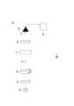
請參照圖1,圖1係繪示依照本揭露之一些實施方式之濃度感測系統的示意圖。本揭露之濃度感測系統100藉由非侵入式的方式感測樣品S1的濃度。在一些實施方式中,樣品S1為生物組織液,生物組織液可包含,但不受限於,去離子水、葡萄糖粉、以及脂質粒等等。在一些例子中,濃度感測系統100可用於感測血糖的濃度,故可應用於非侵入式的血糖檢測裝置上。進一步地,在一例子中,可縮小濃度感測系統100整體的尺寸,以作成穿戴式血糖感測裝置。Please refer to FIG. 1 , which is a schematic diagram of a concentration sensing system according to some embodiments of the present disclosure. The
請參照圖1,濃度感測系統100包含雷射源200、第一偏振裝置300、旋轉裝置400、第二偏振裝置500、第一光接收器600、以及處理模組700。雷射源200配置以朝第一方向D1發射光線。在一實施方式中,雷射源200所發出之光線可以是可見光、紅外線、或任何其他可用以檢測樣品S1之電磁波。本揭露之雷射源200並不限於任何波源,惟只須能穿透樣品S1或被樣品S1反射,並可使處理模組700在接收後進行分析即可。Referring to FIG. 1 , the
如圖1所示,第一偏振裝置300設在位於第一方向D1上,並位於樣品S1與雷射源200之間。第一偏振裝置300具有第一偏振方向。第一偏振裝置300配置以使光線在通過第一偏振裝置300後具有第一偏振態,並可對入射光線的電場作選擇,使電場方向與第一偏振方向垂直的光線無法通過。在一些實施方式中,定義第一偏振裝置300之偏振角度為0度。在一些實施方式中,第一偏振裝置300可以包含改變電磁波偏振狀態的任何裝置,例如偏振片、液晶等等。As shown in FIG1 , the
第二偏振裝置500設在以樣品S1的位置為起點延伸的第二方向D2上。第二偏振裝置500具有第二偏振方向,且配置以使通過第二偏振裝置500之光線具有第二偏振態。具體而言,在光線經過旋轉裝置400以及樣品S1後,光線將藉由透射的方式沿第二方向D2前進,並射向位在第二方向D2上的第二偏振裝置500。第二偏振裝置500可對入射光線的電場作選擇,使電場方向與第二偏振方向垂直的光線無法通過。在一些實施方式中,定義第二偏振裝置500之偏振角度為90度。在一些例子中,第一偏振裝置300的第一偏振方向與第二偏振裝置500的第二偏振方向垂直,故第一偏振裝置300可作為起偏板(polarizer),用以將非偏振光變為偏振光,而第二偏振裝置500可作為檢偏板(analyzer),用以檢驗偏振光的狀態。The
旋轉裝置400設在第一偏振裝置300與第二偏振裝置500之間。旋轉裝置400配置以使光線之光強度在經過旋轉裝置400後成為角頻率的函數。具體而言,旋轉裝置400之偏振方向以光線行進方向為軸作旋轉,並具有角頻率,故通過旋轉裝置400之光線的偏振方向也將隨著旋轉裝置400之偏振方向的旋轉而旋轉,且光線的光強度可以角頻率的函數表示。The
此外,旋轉裝置400可以透過馬達(未繪示)的驅動來旋轉,其中上述馬達的轉軸是空心的,並可沿著第一方向D1延伸,以使轉軸具有可供光線穿透的通孔。如此,旋轉裝置400能沿著平行於第一方向D1的軸心(相當於圖1所示的第一方向D1)而旋轉,而光線(例如雷射源200發出的光線)能穿透旋轉裝置400與前述馬達。In addition, the
須強調的是,本揭露之圖1僅僅作為例示,而非用以限定作為目的。在一些實施方式中,旋轉裝置400係設在第一偏振裝置300與樣品S1之間,故光線在通過第一偏振裝置300後會先通過旋轉裝置400,再通過樣品S1。在另一些實施方式中,旋轉裝置400設在樣品S1與第二偏振裝置500之間,故光線在通過第一偏振裝置300後會先通過樣品S1,再通過旋轉裝置400。在此二實施方式中,旋轉裝置400皆可達到使光線的強度成為角頻率的函數的功效,故此二實施方式中,通過旋轉裝置400的光線皆可進行時變分析。在一些例子中,旋轉裝置400包含旋轉偏振器。在另一些例子中,旋轉裝置400包含法拉第旋光器。It should be emphasized that FIG. 1 of the present disclosure is only for illustration and is not intended to be limiting. In some embodiments, the
如圖1所示,第一光接收器600設在第二方向D2上,且配置以接收來自第二偏振裝置500之光線。在一些實施方式中,雷射源200發射光線之第一方向D1與第二方向D2平行,且濃度感測系統100為穿透式濃度感測系統,即光線與樣品S1作用後產生之光線將穿透樣品S1,並沿第二方向D2穿過第二偏振裝置500,最後到達第一光接收器600。As shown in FIG1 , the
處理模組700訊號連接第一光接收器600。處理模組700配置以根據第一光接收器600測量到的光線的光強度計算出對應的穆勒矩陣(Mueller matrix),並根據穆勒矩陣計算出對應的旋轉角,再根據旋轉角計算出對應之樣品S1的濃度。The
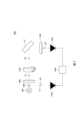
請參照圖2,圖2係繪示依照本揭露之另一些實施方式之濃度感測系統的示意圖。在此實施方式中,類似於濃度感測系統100,濃度感測系統800包含雷射源900、第一偏振裝置1000、旋轉裝置1100、第二偏振裝置1200、第一光接收器1300、分光器1400、第二光接收器1500、以及處理模組1600。由於濃度感測系統800之雷射源900、第一偏振裝置1000、旋轉裝置1100、第二偏振裝置1200、第一光接收器1300、以及處理模組1600皆與圖1中對應之相同名稱之元件的功能相同,故在此不再贅述。濃度感測系統800與濃度感測系統100的主要差異在於,雷射源900與樣品S1之間的第一方向D1與以樣品S1的位置為起點延伸的第二方向D2垂直。Please refer to FIG. 2 , which is a schematic diagram of a concentration sensing system according to other embodiments of the present disclosure. In this embodiment, similar to the
此時,濃度感測系統800為反射式濃度感測系統,即光線照射樣品S1後產生之光線將經由樣品S1反射,並沿第二方向D2穿過第二偏振裝置1200,最後到達第一光接收器1300。在本實施方式中,濃度感測系統800更包含分光器1400。分光器1400設在雷射源900與第一偏振裝置1000之間。分光器1400配置以將雷射源900所發射之光線分裂為第一光線L1與第二光線L2,其中第一光線L1沿第一方向D1前進,第二光線L2沿第三方向D3前進。另外,須說明的是,在其他實施例中,濃度感測系統800可以不包含分光器1400,所以圖2所示的分光器1400僅供舉例說明,不限定本發明。At this time, the
在一些實施方式中,濃度感測系統800更包含第二光接收器1500。第二光接收器1500訊號連接處理模組1600。第二光接收器1500配置以接收沿第三方向D3前進的第二光線L2。在這些實施方式中,處理模組1600更配置以藉由第二光線L2抵銷第一光線L1經由樣品S1反射後產生之光線的幾何擾動所產生的誤差,故可提升處理模組1600所接收之光線的準確性。In some embodiments, the
以下將說明如何根據穆勒矩陣與光線的強度來計算出樣品的濃度。為說明入射光與在經過光學系統作用後出射之出射光的關係,首先介紹史托克斯向量(stokes vector)。史托克斯向量係用以描述電磁輻射之偏振態的向量,其可用一組4x1階之矩陣表示其中為電磁波之強度(intensity),與為電磁波之強度、偏光率(degree of polarization)、橢圓傾角 (orientation angle)、以及橢圓率(elliptical angle)的函數,則是電磁波之強度、偏光率、以及橢圓率的函數。詳細之史托克斯向量的分量如何以電磁波之強度、偏光率、橢圓傾角、以及橢圓率來表示,係為本領域具有通常知識者可理解之知識,故在此不再贅述。The following will explain how to calculate the sample concentration based on the Mueller matrix and the intensity of light. To explain the relationship between the incident light and the outgoing light after passing through the optical system, we first introduce the Stokes vector. The Stokes vector is a vector used to describe the polarization state of electromagnetic radiation, which can be represented by a 4x1 matrix. in is the intensity of electromagnetic waves. and It is a function of the intensity of the electromagnetic wave, the degree of polarization, the orientation angle, and the elliptical angle. It is a function of the intensity, polarization, and ellipticity of the electromagnetic wave. The details of how the components of the Stokes vector are expressed in terms of the intensity, polarization, elliptic tilt, and ellipticity of the electromagnetic wave are known to those with ordinary knowledge in this field, so we will not elaborate on them here.
假定入射光之史托克斯向量為,在入射光經過光學系統作用後之出射光的史托克斯向量為,則與之間的關係可用以下之關係式來表示其中M為4x4階之穆勒矩陣。穆勒矩陣中之元(entry)與光學系統之配置有關。具體而言,本揭露之濃度感測系統100利用穆勒矩陣的元與光旋轉角(optical rotation angle)相關的特性,運用時變分析來取得光旋轉角,並使用以下式子來求出樣品的濃度其中是光旋轉角,是樣品的旋光度,c是樣品的濃度,L是光通過的光程。因此,本揭露之樣品產生的光旋轉角正比於樣品的濃度與光程的長度。使用者可輕易利用各種測量工具測量光程L,並在測量出光旋轉角後利用已知的物質的旋光度計算出樣品濃度c。Assume that the Stokes vector of the incident light is , the Stokes vector of the outgoing light after the incident light passes through the optical system is , then and The relationship between them can be expressed by the following equation: WhereM is a 4x4 Mueller matrix. The entry in the Mueller matrix is related to the configuration of the optical system. Specifically, the
以下分別針對圖1之濃度感測系統100以及圖2之濃度感測系統800來說明如何根據穆勒矩陣計算出對應的旋轉角。在如圖1所示之濃度感測系統100中,雷射源200發出之光線的史托克斯向量與第一光接收器600所接收之光線的史托克斯向量之間的關係式可表示為其中是第一偏振裝置300的穆勒矩陣,是旋轉裝置400的穆勒矩陣,是樣品S1的穆勒矩陣,且是第二偏振裝置500的穆勒矩陣。進一步地展開式子後,以上之關係式可表示為其中是光旋轉角,是旋轉裝置400的角頻率。經過適當的處理後,第一光接收器600所接收之光線的光強度I可表示為將此式子以傅立葉展開式來表示以上的係數、以及皆可經由處理模組700運用快速傅立葉轉換(Fast Fourier transform,FFT)的方式所得知。有關快速傅立葉轉換的運用係為本領域具有通常知識者可理解之知識,故在此不再贅述。求得係數、以及後,即可運用以下式子來求得光旋轉角以上之運用快速傅立葉轉換取得光強度之傅立葉展開式中的係數,再利用反正切公式取得光螺旋角ψ的方法稱為反正切法(arctangent algorithm)。The following describes how to calculate the corresponding rotation angle according to the Mueller matrix for the
請參照圖3,圖3係繪示依照本揭露之一些實施方式之處理模組的裝置示意圖。在另一些實施方式中,處理模組700可利用鎖相法(lock-in algorithm)來從光強度中取得光旋轉角。在這些實施方式中,處理模組700包含倍數器710、低通濾波器720、以及直流放大器730。倍數器710訊號連接低通濾波器720、輸入訊號源I1、以及參考訊號源I2。在這些實施方式中,輸入訊號源I1將傳送光線至倍數器710,並使光線的訊號與參考訊號源I2的時變參考訊號相乘,藉以得到非時變項。具體而言,參考光線的光強度I中包含角頻率是的項設定參考訊號為藉由倍數器710將訊號與訊號相乘後,即可求得非時變項故通過低通濾波器720過濾高頻項與通過直流放大器730放大非時變項後可得直流訊號故使用者可由此鎖相法輕易得到光旋轉角。Please refer to FIG. 3 , which is a schematic diagram of a processing module according to some embodiments of the present disclosure. In other embodiments, the
以下針對圖2之反射式之濃度感測系統800如何取得穆勒矩陣,並計算出對應的旋轉角來說明。如圖2所示之濃度感測系統800中,雷射源900發出之光線的史托克斯向量與第一光接收器1300所接收之光線的史托克斯向量之間的關係式可表示為其中是第一偏振裝置1000的穆勒矩陣,是旋轉裝置1100的穆勒矩陣,是樣品S1的穆勒矩陣,是第二偏振裝置1200的穆勒矩陣,而是用以模擬散射現象所加入之去極化穆勒矩陣。進一步地展開式子後,以上之關係式可表示為其中、、以及為去極化因子,是光旋轉角,是旋轉裝置1100的角頻率。經過適當的處理後,第一光接收器1300所接收之光線的光強度I可表示為取得此光強度I的表示式後,將此式子以傅立葉展開式來表示以上係數、以及也可經由處理模組1600運用快速傅立葉轉換(FFT)的方式所得知,其中快速傅立葉轉換的運用為本領域具有通常知識者可理解之知識,故在此不再贅述。求得係數、以及後,也可運用反正切法與鎖相法以進一步得出光旋轉角。之後,利用前述載有濃度與光旋轉角關係的公式,得出濃度。The following is an explanation of how to obtain the Mueller matrix and calculate the corresponding rotation angle for the reflective
圖4係繪示依照本揭露之另一些實施方式之濃度感測系統的示意圖。請參閱圖4,濃度感測系統101為穿透式濃度感測系統,並包含旋轉裝置1700,其中在光線入射於旋轉裝置1700之後,旋轉裝置1700也能使光線之光強度成為角頻率的函數,而經過旋轉裝置1700之光線的偏振方向也將隨著旋轉裝置1700的旋轉而旋轉。FIG4 is a schematic diagram of a concentration sensing system according to other embodiments of the present disclosure. Referring to FIG4 , the
本實施例的濃度感測系統101與前述濃度感測系統100相似,而以下主要敘述濃度感測系統101與100之間的差異,兩者相同特徵基本上不再重複敘述。具體而言,濃度感測系統101與100之間的主要差異在於:前述實施例中的旋轉裝置400與1100是穿透式光學元件,但本實施例中的旋轉裝置1700是反射式光學元件。The
旋轉裝置1700能反射雷射源200發出的光線,並將光線反射至樣品S1。因此,有別於圖1所示的實施例,在本實施例中,剛從雷射源200出射的光線會沿著第一方向D1前進,但光線被旋轉裝置1700反射後,會沿著第二方向D2前進,其中圖4中的第一方向D1可垂直於第二方向D2,但不平行於第二方向D2。The
在圖4所示的實施例中,旋轉裝置1700包括反射層1701與光偏振層1702,其中光偏振層1702與反射層1701彼此堆疊。光偏振層1702能改變光線的偏振方向,而反射層1701能反射光線,以使光線入射至樣品S1。此外,旋轉裝置1700可沿著轉軸(未標示)而旋轉,其中此轉軸可垂直於光偏振層1702與反射層1701兩者的平面,如圖4所示,而旋轉裝置1700可透過馬達(未繪示)的驅動來旋轉。In the embodiment shown in FIG. 4 , the
由於旋轉裝置1700能反射光線,因此光線不用穿透旋轉裝置1700的馬達。相較於穿透式的旋轉裝置400與1100,反射式的旋轉裝置1700可採用構造簡單的馬達,其具有實心轉軸。因此,旋轉裝置1700的製造成本與價格可低於旋轉裝置400與1100的製造成本與價格。Since the
圖4所示的旋轉裝置1700也可應用於反射式濃度感測系統,如圖5所示。請參閱圖5,圖5所示的濃度感測系統102與前述實施例的濃度感測系統101相似,而濃度感測系統101與102兩者的主要差異在於:濃度感測系統102為反射式濃度感測系統,並接收被樣品S1反射的光線,以使濃度感測系統102的處理模組701對接收到的光線進行時變分析,其中處理模組701可以是前述的處理模組700或1600,而上述時變分析以感測濃度的方法已揭露於前述實施例中,不再重複敘述。The
值得一提的是,旋轉裝置1700可以使用於前述圖2中的濃度感測系統800。具體而言,在圖2所示的濃度感測系統800中,穿透式的旋轉裝置1100可替換成反射式的旋轉裝置1700,而本案所屬技術領域中具有通常知識者可對濃度感測系統800做簡單的光路調整,以使旋轉裝置1700能使用於濃度感測系統800。因此,須強調的是,反射式的旋轉裝置1700也能使用於濃度感測系統800,不限定僅使用於濃度感測系統101與102。It is worth mentioning that the
由上述本揭露實施方式可知,本揭露主要是透過旋轉裝置的設計,使雷射源發射出來的光在經過旋轉裝置後成為角頻率的函數,故可運用於時變分析。光在射向樣品後將產生旋轉角,並在沿第二方向穿過第二偏振裝置後由第一光接收器所接收。在接收光線後,處理模組將進行時變分析,並從對應產生的穆勒矩陣中推算出樣品的濃度,因此本揭露之濃度感測系統在應用於血糖濃度測量時無須侵入人體即可測量血糖濃度。另外,本揭露之濃度感測系統還包含第二光接收器,第二光接收器在接收分光器所分離出的光線後將傳送光至處理模組,藉以抵銷光線之幾何擾動所產生的誤差,進而提升濃度感測系統的量測準確度。From the above-mentioned implementation methods of the present disclosure, it can be known that the present disclosure mainly uses the design of a rotating device to make the light emitted by the laser source become a function of angular frequency after passing through the rotating device, so it can be used for time-varying analysis. After the light is emitted to the sample, a rotation angle will be generated, and it will be received by the first light receiver after passing through the second polarization device along the second direction. After receiving the light, the processing module will perform time-varying analysis and deduce the concentration of the sample from the corresponding Mueller matrix. Therefore, when the concentration sensing system of the present disclosure is applied to blood sugar concentration measurement, it can measure blood sugar concentration without invading the human body. In addition, the concentration sensing system disclosed herein further includes a second light receiver, which transmits the light to the processing module after receiving the light separated by the spectrometer, so as to offset the error caused by the geometric disturbance of the light, thereby improving the measurement accuracy of the concentration sensing system.
雖然本揭露已以實施例揭露如上,然其並非用以限定本揭露,任何所屬技術領域中具有通常知識者,在不脫離本揭露的精神和範圍內,當可作些許的更動與潤飾,故本揭露的保護範圍當視後附的申請專利範圍所界定者為準。Although the present disclosure has been disclosed as above by way of embodiments, it is not intended to limit the present disclosure. Any person having ordinary knowledge in the relevant technical field may make some changes and modifications without departing from the spirit and scope of the present disclosure. Therefore, the protection scope of the present disclosure shall be subject to the definition of the attached patent application scope.
100、101、102:濃度感測系統 200:雷射源 300:第一偏振裝置 400:旋轉裝置 500:第二偏振裝置 600:第一光接收器 700、701:處理模組 710:倍數器 720:低通濾波器 730:直流放大器 800:濃度感測系統 900:雷射源 1000:第一偏振裝置 1100:旋轉裝置 1200:第二偏振裝置 1300:第一光接收器 1400:分光器 1500:第二光接收器 1600:處理模組 1700:旋轉裝置 1701:反射層 1702:光偏振層 D1:第一方向 D2:第二方向 D3:第三方向 I1:輸入訊號源 I2:參考訊號源 L1:第一光線 L2:第二光線 S1:樣品100, 101, 102: Concentration sensing system200: Laser source300: First polarization device400: Rotation device500: Second polarization device600: First
為讓本發明之上述和其他目的、特徵、優點與實施例能更明顯易懂,所附圖式之詳細說明如下: 圖1係繪示依照本揭露之一些實施方式之濃度感測系統的示意圖。 圖2係繪示依照本揭露之另一些實施方式之濃度感測系統的示意圖。 圖3係繪示依照本揭露之一些實施方式之處理模組的裝置示意圖。 圖4係繪示依照本揭露之另一些實施方式之濃度感測系統的示意圖。 圖5係繪示依照本揭露之另一些實施方式之濃度感測系統的示意圖。In order to make the above and other purposes, features, advantages and embodiments of the present invention more clearly understandable, the detailed description of the attached figures is as follows: FIG. 1 is a schematic diagram of a concentration sensing system according to some embodiments of the present disclosure. FIG. 2 is a schematic diagram of a concentration sensing system according to other embodiments of the present disclosure. FIG. 3 is a schematic diagram of a device of a processing module according to some embodiments of the present disclosure. FIG. 4 is a schematic diagram of a concentration sensing system according to other embodiments of the present disclosure. FIG. 5 is a schematic diagram of a concentration sensing system according to other embodiments of the present disclosure.
國內寄存資訊(請依寄存機構、日期、號碼順序註記) 無 國外寄存資訊(請依寄存國家、機構、日期、號碼順序註記) 無Domestic storage information (please note in the order of storage institution, date, and number)NoneForeign storage information (please note in the order of storage country, institution, date, and number)None
800:濃度感測系統 900:雷射源 1000:第一偏振裝置 1100:旋轉裝置 1200:第二偏振裝置 1300:第一光接收器 1400:分光器 1500:第二光接收器 1600:處理模組 D1:第一方向 D2:第二方向 D3:第三方向 L1:第一光線 L2:第二光線 S1:樣品800: Concentration sensing system900: Laser source1000: First polarization device1100: Rotation device1200: Second polarization device1300: First light receiver1400: Spectrometer1500: Second light receiver1600: Processing moduleD1: First directionD2: Second directionD3: Third directionL1: First lightL2: Second lightS1: Sample
Claims (11)
Translated fromChineseApplications Claiming Priority (2)
| Application Number | Priority Date | Filing Date | Title |
|---|---|---|---|
| US202363480497P | 2023-01-18 | 2023-01-18 | |
| US63/480,497 | 2023-01-18 |
Publications (2)
| Publication Number | Publication Date |
|---|---|
| TW202430858A TW202430858A (en) | 2024-08-01 |
| TWI854504Btrue TWI854504B (en) | 2024-09-01 |
Family
ID=93260186
Family Applications (1)
| Application Number | Title | Priority Date | Filing Date |
|---|---|---|---|
| TW112106522ATWI854504B (en) | 2023-01-18 | 2023-02-22 | System of sensing concentration |
Country Status (1)
| Country | Link |
|---|---|
| TW (1) | TWI854504B (en) |
Citations (4)
| Publication number | Priority date | Publication date | Assignee | Title |
|---|---|---|---|---|
| US20050264813A1 (en)* | 2003-06-25 | 2005-12-01 | George Giakos | Multi-wavelength imaging system |
| TW200928348A (en)* | 2007-12-31 | 2009-07-01 | Univ Far East | Device for synchronous measurement of optical rotation angle and phase delay and method thereof |
| TW201831882A (en)* | 2017-02-16 | 2018-09-01 | 國立成功大學 | Method and system for sensing glucose concentration |
| TW202215028A (en)* | 2020-09-30 | 2022-04-16 | 國立成功大學 | System and method for sensing concentration |
- 2023
- 2023-02-22TWTW112106522Apatent/TWI854504B/enactive
Patent Citations (4)
| Publication number | Priority date | Publication date | Assignee | Title |
|---|---|---|---|---|
| US20050264813A1 (en)* | 2003-06-25 | 2005-12-01 | George Giakos | Multi-wavelength imaging system |
| TW200928348A (en)* | 2007-12-31 | 2009-07-01 | Univ Far East | Device for synchronous measurement of optical rotation angle and phase delay and method thereof |
| TW201831882A (en)* | 2017-02-16 | 2018-09-01 | 國立成功大學 | Method and system for sensing glucose concentration |
| TW202215028A (en)* | 2020-09-30 | 2022-04-16 | 國立成功大學 | System and method for sensing concentration |
Non-Patent Citations (1)
| Title |
|---|
| 期刊 Zhi-Yu Cai, Yu-Lung Lo , Ching-Min Chang Dual-rotator mueller matrix polarimeter for high-accuracy and high-precision measurements of glucose concentration 245 (2021) Optik Available online 21 July 2021* |
Also Published As
| Publication number | Publication date |
|---|---|
| TW202430858A (en) | 2024-08-01 |
Similar Documents
| Publication | Publication Date | Title |
|---|---|---|
| JP4556463B2 (en) | Birefringence measuring device | |
| Layden et al. | Quantitative polarimetry for tissue characterization and diagnosis | |
| JP6323867B2 (en) | Scattering spectrometer | |
| WO2010100766A1 (en) | Optical rotation measuring device and optical rotation measuring method | |
| US8718734B2 (en) | Non-invasive polarimetric apparatus and method for analyte sensing in birefringent media | |
| CN104706363B (en) | Composite type photoacoustic nondestructive dynamic blood sugar detector | |
| CN104755924B (en) | monosaccharide concentration sensor and method | |
| JP2001500037A (en) | Photonic molecular probe | |
| WO2015136956A1 (en) | Measurement device and measurement method | |
| US5956144A (en) | Method and apparatus for use of polarized light vectors in identifying and evaluating constituent compounds in a specimen | |
| US20160018327A1 (en) | Differential OCT Analysis System | |
| Co^ te´ et al. | Balanced detection for low-noise precision polarimetric measurements of optically active, multiply scattering tissue phantoms | |
| TWI854504B (en) | System of sensing concentration | |
| US9713441B2 (en) | Optical rotation measurement method and optical rotation measurement apparatus | |
| TWI758891B (en) | System and method for sensing concentration | |
| EP0721575A1 (en) | Method and apparatus for use of polarized light vectors in evaluating constituent compounds in a specimen | |
| Zabolotna et al. | System of polarization phasometry of polycrystalline blood plasma networks in mammary gland pathology diagnostics | |
| Al-Nabulsi et al. | Non-invasive sensing techniques for glucose detection: a review | |
| Wood et al. | Towards noninvasive glucose sensing using polarization analysis of multiply scattered light | |
| WO2013179140A2 (en) | Optical rotation measuring device, optically rotational ingredient analyzing device, and optically rotational ingredient analyzing method | |
| TWI464387B (en) | Heterodyne interferometer based on the subtraction between optical interference signals designed for measuring the ellipsometric parameters of thin films | |
| Kruchinina et al. | Investigation of red blood cells from patients with diffuse liver diseases by combined dielectrophoresis and terahertz spectroscopy method | |
| Mahajan et al. | Measurement of concentration of sugar in solutions with laser speckle decorrelation | |
| US10512425B2 (en) | Dermatologically non-abrasive blood testing using an interferometry optical design | |
| JP5374762B2 (en) | Reflective birefringence measuring device |