TWI852101B - Film manufacturing equipment and method of manufacturing film - Google Patents
Film manufacturing equipment and method of manufacturing filmDownload PDFInfo
- Publication number
- TWI852101B TWI852101BTW111136829ATW111136829ATWI852101BTW I852101 BTWI852101 BTW I852101BTW 111136829 ATW111136829 ATW 111136829ATW 111136829 ATW111136829 ATW 111136829ATW I852101 BTWI852101 BTW I852101B
- Authority
- TW
- Taiwan
- Prior art keywords
- solution
- substrate
- guide surface
- thin film
- conveying
- Prior art date
Links
Images


Classifications
- B—PERFORMING OPERATIONS; TRANSPORTING
- B05—SPRAYING OR ATOMISING IN GENERAL; APPLYING FLUENT MATERIALS TO SURFACES, IN GENERAL
- B05C—APPARATUS FOR APPLYING FLUENT MATERIALS TO SURFACES, IN GENERAL
- B05C5/00—Apparatus in which liquid or other fluent material is projected, poured or allowed to flow on to the surface of the work
- B05C5/02—Apparatus in which liquid or other fluent material is projected, poured or allowed to flow on to the surface of the work the liquid or other fluent material being discharged through an outlet orifice by pressure, e.g. from an outlet device in contact or almost in contact, with the work
- B05C5/0245—Apparatus in which liquid or other fluent material is projected, poured or allowed to flow on to the surface of the work the liquid or other fluent material being discharged through an outlet orifice by pressure, e.g. from an outlet device in contact or almost in contact, with the work for applying liquid or other fluent material to a moving work of indefinite length, e.g. to a moving web
- B—PERFORMING OPERATIONS; TRANSPORTING
- B05—SPRAYING OR ATOMISING IN GENERAL; APPLYING FLUENT MATERIALS TO SURFACES, IN GENERAL
- B05D—PROCESSES FOR APPLYING FLUENT MATERIALS TO SURFACES, IN GENERAL
- B05D3/00—Pretreatment of surfaces to which liquids or other fluent materials are to be applied; After-treatment of applied coatings, e.g. intermediate treating of an applied coating preparatory to subsequent applications of liquids or other fluent materials
- B05D3/02—Pretreatment of surfaces to which liquids or other fluent materials are to be applied; After-treatment of applied coatings, e.g. intermediate treating of an applied coating preparatory to subsequent applications of liquids or other fluent materials by baking
- B05D3/0254—After-treatment
- B—PERFORMING OPERATIONS; TRANSPORTING
- B05—SPRAYING OR ATOMISING IN GENERAL; APPLYING FLUENT MATERIALS TO SURFACES, IN GENERAL
- B05D—PROCESSES FOR APPLYING FLUENT MATERIALS TO SURFACES, IN GENERAL
- B05D3/00—Pretreatment of surfaces to which liquids or other fluent materials are to be applied; After-treatment of applied coatings, e.g. intermediate treating of an applied coating preparatory to subsequent applications of liquids or other fluent materials
- B05D3/04—Pretreatment of surfaces to which liquids or other fluent materials are to be applied; After-treatment of applied coatings, e.g. intermediate treating of an applied coating preparatory to subsequent applications of liquids or other fluent materials by exposure to gases
- B05D3/0406—Pretreatment of surfaces to which liquids or other fluent materials are to be applied; After-treatment of applied coatings, e.g. intermediate treating of an applied coating preparatory to subsequent applications of liquids or other fluent materials by exposure to gases the gas being air
- G—PHYSICS
- G03—PHOTOGRAPHY; CINEMATOGRAPHY; ANALOGOUS TECHNIQUES USING WAVES OTHER THAN OPTICAL WAVES; ELECTROGRAPHY; HOLOGRAPHY
- G03F—PHOTOMECHANICAL PRODUCTION OF TEXTURED OR PATTERNED SURFACES, e.g. FOR PRINTING, FOR PROCESSING OF SEMICONDUCTOR DEVICES; MATERIALS THEREFOR; ORIGINALS THEREFOR; APPARATUS SPECIALLY ADAPTED THEREFOR
- G03F7/00—Photomechanical, e.g. photolithographic, production of textured or patterned surfaces, e.g. printing surfaces; Materials therefor, e.g. comprising photoresists; Apparatus specially adapted therefor
- G03F7/16—Coating processes; Apparatus therefor
- G03F7/168—Finishing the coated layer, e.g. drying, baking, soaking
- B—PERFORMING OPERATIONS; TRANSPORTING
- B05—SPRAYING OR ATOMISING IN GENERAL; APPLYING FLUENT MATERIALS TO SURFACES, IN GENERAL
- B05C—APPARATUS FOR APPLYING FLUENT MATERIALS TO SURFACES, IN GENERAL
- B05C5/00—Apparatus in which liquid or other fluent material is projected, poured or allowed to flow on to the surface of the work
- B05C5/02—Apparatus in which liquid or other fluent material is projected, poured or allowed to flow on to the surface of the work the liquid or other fluent material being discharged through an outlet orifice by pressure, e.g. from an outlet device in contact or almost in contact, with the work
- B05C5/0254—Coating heads with slot-shaped outlet
- B—PERFORMING OPERATIONS; TRANSPORTING
- B05—SPRAYING OR ATOMISING IN GENERAL; APPLYING FLUENT MATERIALS TO SURFACES, IN GENERAL
- B05D—PROCESSES FOR APPLYING FLUENT MATERIALS TO SURFACES, IN GENERAL
- B05D1/00—Processes for applying liquids or other fluent materials
- B05D1/26—Processes for applying liquids or other fluent materials performed by applying the liquid or other fluent material from an outlet device in contact with, or almost in contact with, the surface
- B—PERFORMING OPERATIONS; TRANSPORTING
- B05—SPRAYING OR ATOMISING IN GENERAL; APPLYING FLUENT MATERIALS TO SURFACES, IN GENERAL
- B05D—PROCESSES FOR APPLYING FLUENT MATERIALS TO SURFACES, IN GENERAL
- B05D2252/00—Sheets
- B05D2252/02—Sheets of indefinite length
- B—PERFORMING OPERATIONS; TRANSPORTING
- B05—SPRAYING OR ATOMISING IN GENERAL; APPLYING FLUENT MATERIALS TO SURFACES, IN GENERAL
- B05D—PROCESSES FOR APPLYING FLUENT MATERIALS TO SURFACES, IN GENERAL
- B05D3/00—Pretreatment of surfaces to which liquids or other fluent materials are to be applied; After-treatment of applied coatings, e.g. intermediate treating of an applied coating preparatory to subsequent applications of liquids or other fluent materials
- B05D3/02—Pretreatment of surfaces to which liquids or other fluent materials are to be applied; After-treatment of applied coatings, e.g. intermediate treating of an applied coating preparatory to subsequent applications of liquids or other fluent materials by baking
- B05D3/0254—After-treatment
- B05D3/0272—After-treatment with ovens
- B—PERFORMING OPERATIONS; TRANSPORTING
- B05—SPRAYING OR ATOMISING IN GENERAL; APPLYING FLUENT MATERIALS TO SURFACES, IN GENERAL
- B05D—PROCESSES FOR APPLYING FLUENT MATERIALS TO SURFACES, IN GENERAL
- B05D3/00—Pretreatment of surfaces to which liquids or other fluent materials are to be applied; After-treatment of applied coatings, e.g. intermediate treating of an applied coating preparatory to subsequent applications of liquids or other fluent materials
- B05D3/04—Pretreatment of surfaces to which liquids or other fluent materials are to be applied; After-treatment of applied coatings, e.g. intermediate treating of an applied coating preparatory to subsequent applications of liquids or other fluent materials by exposure to gases
- B05D3/0406—Pretreatment of surfaces to which liquids or other fluent materials are to be applied; After-treatment of applied coatings, e.g. intermediate treating of an applied coating preparatory to subsequent applications of liquids or other fluent materials by exposure to gases the gas being air
- B05D3/0413—Heating with air
Landscapes
- Physics & Mathematics (AREA)
- General Physics & Mathematics (AREA)
- Application Of Or Painting With Fluid Materials (AREA)
- Coating Apparatus (AREA)
- Separation Using Semi-Permeable Membranes (AREA)
Abstract
Description
Translated fromChinese本發明是關於一種薄膜製造設備及以此設備製造薄膜的方法。The present invention relates to a thin film manufacturing device and a method for manufacturing a thin film using the device.
隨著近年來世界各地受到疫情的肆虐,人們為了保護自己和家人,都積極地使用醫療級別的個人防護裝備,而醫療口罩更成為了現今生活中不可或缺的日常用品。As the world has been ravaged by the epidemic in recent years, people have actively used medical-grade personal protective equipment to protect themselves and their families, and medical masks have become an indispensable daily necessity in today's life.
一般而言,生物多孔膜是製成醫療口罩的一個重要材料,因此,如何能在低成本而環保的情況下,有效提升生物多孔膜的產能及良率,以避免市場上出現醫療口罩短缺的情況,無疑是業界相當關注的重要議題。Generally speaking, bioporous membrane is an important material for making medical masks. Therefore, how to effectively improve the production capacity and yield of bioporous membrane at a low cost and in an environmentally friendly way to avoid the shortage of medical masks in the market is undoubtedly an important issue that the industry is concerned about.
本發明之目的之一在於提供一種薄膜製造設備,其能有效提升生產薄膜的效率及品質。One of the purposes of the present invention is to provide a thin film manufacturing device that can effectively improve the efficiency and quality of thin film production.
根據本發明的一實施方式,一種薄膜製造設備包含輸送裝置、過濾裝置、塗佈裝置、烘烤裝置以及吹氣裝置。輸送裝置配置以輸送基材。過濾裝置配置以過濾溶液。塗佈裝置配置以把經過濾之溶液擠出並塗佈於基材上。烘烤裝置配置以烘烤塗佈於基材上之溶液。吹氣裝置配置以對經烘烤之溶液進行吹氣。According to an embodiment of the present invention, a thin film manufacturing device includes a conveying device, a filtering device, a coating device, a baking device, and a blowing device. The conveying device is configured to convey a substrate. The filtering device is configured to filter a solution. The coating device is configured to extrude the filtered solution and coat it on the substrate. The baking device is configured to bake the solution coated on the substrate. The blowing device is configured to blow air on the baked solution.
在本發明一或多個實施方式中,上述之過濾裝置包含至少一過濾材料,過濾材料具有複數個過濾孔,過濾孔中每一者之尺寸範圍為5微米與50微米之間。In one or more embodiments of the present invention, the filter device comprises at least one filter material having a plurality of filter holes, and the size of each of the filter holes ranges from 5 microns to 50 microns.
在本發明一或多個實施方式中,上述之塗佈裝置配置以沿第一方向向基材輸送經過濾之溶液,輸送裝置配置以沿第二方向輸送基材,第一方向與第二方向彼此相交。In one or more embodiments of the present invention, the coating device is configured to transport the filtered solution to the substrate along a first direction, and the transport device is configured to transport the substrate along a second direction, and the first direction and the second direction intersect each other.
在本發明一或多個實施方式中,上述之塗佈裝置包含主體、第一移動部以及第二移動部。主體具有第一輸送管道,第一輸送管道配置以讓經過濾之溶液流經。第一移動部沿第三方向可滑動地連接主體,第三方向傾斜於第一方向。第二移動部沿第四方向可滑動地連接主體,第四方向垂直於第一方向。第一移動部與第二移動部之間定義第二輸送管道,第二輸送管道位於第一輸送管道與輸送裝置之間,並至少部分沿第一方向連通第一輸送管道。In one or more embodiments of the present invention, the coating device comprises a main body, a first moving part and a second moving part. The main body has a first delivery channel, and the first delivery channel is configured to allow the filtered solution to flow through. The first moving part is slidably connected to the main body along a third direction, and the third direction is inclined to the first direction. The second moving part is slidably connected to the main body along a fourth direction, and the fourth direction is perpendicular to the first direction. A second delivery channel is defined between the first moving part and the second moving part, and the second delivery channel is located between the first delivery channel and the delivery device, and is at least partially connected to the first delivery channel along the first direction.
在本發明一或多個實施方式中,上述之第一輸送管道具有第一寬度,第二輸送管道具有第二寬度,第一寬度大於第二寬度。In one or more embodiments of the present invention, the first conveying pipe has a first width, the second conveying pipe has a second width, and the first width is greater than the second width.
在本發明一或多個實施方式中,上述之第一寬度的範圍為6公釐與12公釐之間,第二寬度的範圍為5公釐與10公釐之間。In one or more embodiments of the present invention, the first width is in the range of 6 mm to 12 mm, and the second width is in the range of 5 mm to 10 mm.
在本發明一或多個實施方式中,上述之第二移動部包含第一導引面以及第二導引面。第一導引面定義第二輸送管道。第二導引面至少部分朝向輸送裝置並至少部分傾斜於第一導引面,第二導引面具有相對之第一邊緣以及第二邊緣,第一邊緣連接第一導引面,第二邊緣與輸送裝置之間相隔若干距離。In one or more embodiments of the present invention, the second moving part includes a first guide surface and a second guide surface. The first guide surface defines a second conveying channel. The second guide surface at least partially faces the conveying device and is at least partially inclined to the first guide surface. The second guide surface has a first edge and a second edge opposite to each other. The first edge is connected to the first guide surface, and the second edge is separated from the conveying device by a certain distance.
在本發明一或多個實施方式中,上述之距離之範圍為200微米與2000微米之間。In one or more embodiments of the present invention, the aforementioned distance ranges from 200 microns to 2000 microns.
在本發明一或多個實施方式中,上述之第二導引面包含相連接之第一子導引面以及第二子導引面。第一邊緣位於第一子導引面,第二邊緣位於第二子導引面。第一子導引面連接於第一導引面與第二子導引面之間,第一子導引面傾斜於第一導引面及第二子導引面。In one or more embodiments of the present invention, the second guide surface includes a first sub-guide surface and a second sub-guide surface connected to each other. The first edge is located on the first sub-guide surface, and the second edge is located on the second sub-guide surface. The first sub-guide surface is connected between the first guide surface and the second sub-guide surface, and the first sub-guide surface is inclined to the first guide surface and the second sub-guide surface.
本發明之目的之一在於提供一種薄膜的製造方法,其能有效提升生產薄膜的效率及品質。One of the purposes of the present invention is to provide a method for manufacturing a thin film, which can effectively improve the efficiency and quality of thin film production.
根據本發明的一實施方式,一種薄膜的製造方法包含:(一)輸送一基材;(二)過濾溶液,溶液之黏度範圍為100釐泊秒(cPs)與500釐泊秒之間,溶液之固含量範圍為5%與9%之間;(三)把經過濾之溶液塗佈於基材上;(四)烘烤塗佈於基材上之溶液;以及(五)對經烘烤之溶液進行吹氣。According to one embodiment of the present invention, a method for manufacturing a thin film includes: (1) transporting a substrate; (2) filtering a solution, wherein the viscosity of the solution ranges from 100 centipoise seconds (cPs) to 500 centipoise seconds, and the solid content of the solution ranges from 5% to 9%; (3) coating the filtered solution on the substrate; (4) baking the solution coated on the substrate; and (5) blowing air on the baked solution.
在本發明一或多個實施方式中,上述過濾溶液之步驟包含:以過濾材料過濾溶液,過濾材料具有複數個過濾孔,過濾孔中每一者之尺寸範圍為5微米與50微米之間。In one or more embodiments of the present invention, the step of filtering the solution includes: filtering the solution with a filter material, wherein the filter material has a plurality of filter holes, and the size of each of the filter holes ranges from 5 microns to 50 microns.
在本發明一或多個實施方式中,上述烘烤塗佈於基材上之溶液之步驟包含:去除基材上40%~70%之溶液。In one or more embodiments of the present invention, the step of baking the solution coated on the substrate includes: removing 40% to 70% of the solution on the substrate.
在本發明一或多個實施方式中,上述把經過濾之溶液塗佈於基材上之步驟包含:以塗佈裝置把經過濾之溶液擠出並塗佈於基材上。上述之方法更包含:維持塗佈裝置與基材之間之最短距離,最短距離之範圍為200微米與2000微米之間。In one or more embodiments of the present invention, the step of applying the filtered solution on the substrate includes: extruding the filtered solution with a coating device and applying it on the substrate. The method further includes: maintaining the shortest distance between the coating device and the substrate, and the shortest distance ranges from 200 microns to 2000 microns.
在本發明一或多個實施方式中,上述把經過濾之溶液擠出之步驟包含:調節把溶液擠出之流量速度。In one or more embodiments of the present invention, the step of extruding the filtered solution includes: adjusting the flow rate of extruding the solution.
在本發明一或多個實施方式中,上述輸送基材之步驟包含:調節輸送基材之移動速度。In one or more embodiments of the present invention, the step of transporting the substrate includes: adjusting the moving speed of the transported substrate.
本發明上述實施方式至少具有以下優點:The above-mentioned embodiments of the present invention have at least the following advantages:
(1)由於塗佈裝置係把經過濾之高黏度溶液擠出並塗佈於基材上,因此,當烘烤裝置去除基材上40%~70%之溶液後,即可以吹氣裝置對溶液吹氣以去除殘留於溶液上之細微粉塵,故能有效提升產能及品質。(1) Since the coating device squeezes out the filtered high-viscosity solution and coats it on the substrate, after the baking device removes 40% to 70% of the solution on the substrate, the blowing device can blow air into the solution to remove the fine dust remaining on the solution, thereby effectively improving production capacity and quality.
(2)由於薄膜的製造方法中的步驟簡單容易,故能有效降低製程中的各類損耗,有效達到精實與環保生產的目的。(2) Since the steps in the film manufacturing method are simple and easy, it can effectively reduce various types of losses in the process and effectively achieve the goals of lean and environmentally friendly production.
(3)在薄膜製造設備運作時,藉由維持塗佈裝置與基材之間之距離的大小、調節溶液從塗佈裝置擠出之流量速度以及調節輸送基材之移動速度,可以提升薄膜的生產品質。(3) When the thin film manufacturing equipment is in operation, the production quality of the thin film can be improved by maintaining the distance between the coating device and the substrate, adjusting the flow rate of the solution extruded from the coating device, and adjusting the moving speed of the transport substrate.
以下將以圖式揭露本發明之複數個實施方式,為明確說明起見,許多實務上的細節將在以下敘述中一併說明。然而,應瞭解到,這些實務上的細節不應用以限制本發明。也就是說,在本發明部分實施方式中,這些實務上的細節是非必要的。此外,為簡化圖式起見,一些習知慣用的結構與元件在圖式中將以簡單示意的方式繪示之,而在所有圖式中,相同的標號將用於表示相同或相似的元件。且若實施上為可能,不同實施例的特徵係可以交互應用。The following will disclose multiple embodiments of the present invention with drawings. For the purpose of clarity, many practical details will be described together in the following description. However, it should be understood that these practical details should not be used to limit the present invention. In other words, in some embodiments of the present invention, these practical details are not necessary. In addition, in order to simplify the drawings, some commonly used structures and components will be shown in the drawings in a simple schematic manner, and in all drawings, the same reference numerals will be used to represent the same or similar components. And if it is possible in practice, the features of different embodiments can be applied interchangeably.
除非另有定義,本文所使用的所有詞彙(包括技術和科學術語)具有其通常的意涵,其意涵係能夠被熟悉此領域者所理解。更進一步的說,上述之詞彙在普遍常用之字典中之定義,在本說明書的內容中應被解讀為與本發明相關領域一致的意涵。除非有特別明確定義,這些詞彙將不被解釋為理想化的或過於正式的意涵。Unless otherwise defined, all terms (including technical and scientific terms) used herein have their usual meanings, which are understood by those familiar with this field. Furthermore, the definitions of the above terms in commonly used dictionaries should be interpreted in the content of this specification as meanings consistent with the relevant fields of the present invention. Unless otherwise clearly defined, these terms will not be interpreted as idealized or overly formal meanings.
請參照第1圖。第1圖為繪示依照本發明一實施方式之薄膜的製造方法500的流程圖。在本實施方式中,如第1圖所示,薄膜的製造方法500包含下列步驟(應了解到,在一些實施方式中所提及的步驟,除特別敘明其順序者外,均可依實際需要調整其前後順序,甚至可同時或部分同時執行):Please refer to FIG. 1. FIG. 1 is a flow chart showing a
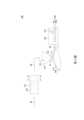
(1)輸送基材200(步驟510)。請參照第2圖。第2圖為繪示依照本發明一實施方式之薄膜製造設備100的結構示意圖。具體而言,在本實施方式中,如第2圖所示,一種薄膜製造設備100包含輸送裝置110,基材200則至少部分設置於輸送裝置110上,而輸送裝置110配置以沿第二方向D2輸送基材200。舉例而言,輸送裝置110藉由轉動而帶動基材200位移,使得第二方向D2實質上為弧形的軌跡。在實務的應用中,舉例而言,基材200為可撓性材質,而其厚度為約100微米,但本發明並不以此為限。(1) Transporting the substrate 200 (step 510). Please refer to FIG. 2. FIG. 2 is a schematic diagram showing the structure of a thin
(2)過濾溶液SL,而溶液SL之黏度範圍為100釐泊秒(cPs)與500釐泊秒之間,且溶液SL之固含量範圍為5%與9%之間(步驟520)。在本實施方式中,如第2圖所示,薄膜製造設備100包含過濾裝置120,過濾裝置120配置以過濾溶液SL。由於溶液SL之黏度範圍為100釐泊秒(cPs)與500釐泊秒之間,故溶液SL具有高黏度。(2) filtering the solution SL, wherein the viscosity of the solution SL is between 100 cPs and 500 cPs, and the solid content of the solution SL is between 5% and 9% (step 520). In the present embodiment, as shown in FIG. 2 , the thin
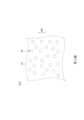
請參照第3圖。第3圖為繪示沿第2圖之線段A-A之局部剖面圖。在本實施方式中,如第2~3圖所示,過濾裝置120包含至少一過濾材料121,過濾材料121具有複數個過濾孔HF,過濾孔HF中每一者之尺寸範圍為5微米與50微米之間。如第3圖所示,過濾孔HF的尺寸為其直徑DM,亦即直徑DM之範圍為5微米與50微米之間。因此,當溶液SL在經過過濾裝置120的過濾材料121時,溶液SL中例如50微米以上不易飄浮而又目視可見之粒子可被過濾材料121有效去除。Please refer to FIG. 3. FIG. 3 is a partial cross-sectional view along the line segment A-A of FIG. 2. In the present embodiment, as shown in FIGS. 2-3, the
再者,在本實施方式中,如第1圖所示,薄膜的製造方法500更包含下列步驟:Furthermore, in this embodiment, as shown in FIG. 1 , the thin
(3)把經過濾之溶液SL塗佈於基材200上(步驟530)。在本實施方式中,如第2圖所示,薄膜製造設備100包含塗佈裝置130,塗佈裝置130配置以接收經過濾裝置120過濾之溶液SL,並沿第一方向D1向設置於輸送裝置110上的基材200輸送經過濾之溶液SL,而第一方向D1與第二方向D2彼此相交。舉例而言,第一方向D1與第二方向D2彼此垂直,但本發明並不以此為限。具體而言,塗佈裝置130配置以把經過濾之溶液SL擠出並垂直地塗佈於被輸送裝置110輸送的基材200上。(3) Applying the filtered solution SL on the substrate 200 (step 530). In the present embodiment, as shown in FIG. 2, the thin
(4)烘烤塗佈於基材200上之溶液SL(步驟540)。在本實施方式中,如第2圖所示,薄膜製造設備100包含烘烤裝置140,烘烤裝置140配置以烘烤塗佈於基材200上之溶液SL。更具體而言,烘烤裝置140配置以去除基材200上40%~70%之溶液SL,以去除基材200上過多之溶液SL並加速溶液SL之凝固。(4) Baking the solution SL coated on the substrate 200 (step 540). In the present embodiment, as shown in FIG. 2, the thin
(5)對經烘烤之溶液SL進行吹氣(步驟550)。在本實施方式中,如第2圖所示,薄膜製造設備100包含吹氣裝置150。舉例而言,吹氣裝置150在結構上可至少部分位於烘烤裝置140內,但本發明並不以此為限。吹氣裝置150配置以例如於烘烤後期對經烘烤之溶液SL進行吹氣,以去除殘留於凝固之溶液SL上之細微粉塵。經吹氣後,薄膜300的製造亦告完成。隨後,薄膜300例如可用以製作醫療口罩,但本發明並不以此為限。(5) Blowing the baked solution SL (step 550). In the present embodiment, as shown in FIG. 2, the
簡單而言,由於塗佈裝置130係把經過濾之高黏度溶液SL擠出並塗佈於基材200上,因此,當烘烤裝置140去除基材200上40%~70%之溶液SL後,即可以吹氣裝置150對溶液SL吹氣以去除殘留於溶液SL上之細微粉塵,故能有效提升生產薄膜300的效率及品質。較佳地,採用薄膜的製造方法500可增加薄膜300的生產效率達30%~50%。In short, since the
進一步而言,如上所述,由於薄膜的製造方法500中的步驟簡單容易,故能有效降低製程中的各類損耗,有效達到精實與環保生產的目的。Furthermore, as described above, since the steps in the thin
請參照第4圖。第4圖為繪示第2圖之範圍B之局部放大圖。在本實施方式中,如第4圖所示,塗佈裝置130包含主體131、第一移動部132以及第二移動部133。主體131具有第一輸送管道C1,第一輸送管道C1配置以讓經過濾之溶液SL流經。第一移動部132沿第三方向D3可滑動地連接主體131,而第三方向D3傾斜於第一方向D1。舉例而言,第三方向D3以45o傾斜於第一方向D1,但本發明並不以此為限。第二移動部133沿第四方向D4可滑動地連接主體131,而第四方向D4垂直於第一方向D1。第一移動部132與第二移動部133之間定義第二輸送管道C2,而第一移動部132與第二移動部133位於主體131與輸送裝置110之間,故第二輸送管道C2位於第一輸送管道C1與輸送裝置110之間,且至少部分沿第一方向D1連通第一輸送管道C1。也就是說,溶液SL先至少部分沿第一方向D1流經第一輸送管道C1,然後再流經第二輸送管道C2,繼而離開塗佈裝置130而抵達基材200。Please refer to FIG. 4. FIG. 4 is a partial enlarged view showing the range B of FIG. 2. In the present embodiment, as shown in FIG. 4, the
進一步而言,如第4圖所示,塗佈裝置130的第一輸送管道C1具有第一寬度W1,第二輸送管道C2具有第二寬度W2,第一寬度W1大於第二寬度W2。藉由第一移動部132相對主體131沿第三方向D3滑動及/或第二移動部133相對主體131沿第四方向D4滑動,第二輸送管道C2的第二寬度W2可根據實際狀況而調整,從以控制溶液SL從塗佈裝置130擠出的流量。在實務的應用中,舉例而言,第一寬度W1的範圍可設定為6公釐與12公釐之間,而第二寬度W2的範圍則可對應地於5公釐與10公釐之間調整。Furthermore, as shown in FIG. 4 , the first delivery channel C1 of the
再者,如第4圖所示,塗佈裝置130的第二移動部133包含第一導引面S1以及第二導引面S2,第一導引面S1定義第二輸送管道C2,而第二導引面S2至少部分朝向輸送裝置110並至少部分傾斜於第一導引面S1,且第二導引面S2具有相對之第一邊緣E1以及第二邊緣E2,第一邊緣E1連接第一導引面S1,第二邊緣E2遠離第一導引面S1,並與輸送裝置110沿中心線CL相隔距離X,而中心線CL穿越輸送裝置110的轉動軸心(圖未示)。值得注意的是,距離X實際上為塗佈裝置130與基材200之間之最短距離。Furthermore, as shown in FIG. 4 , the second moving
具體而言,當薄膜製造設備100運作時,輸送裝置110轉動而帶動基材200沿第二方向D2位移,而塗佈裝置130把經過濾之溶液SL擠出並垂直地(即沿第一方向D1)塗佈於移動中的基材200上,而塗佈於基材200上的溶液SL,亦隨基材200沿第二方向D2位移並通過第二移動部133與輸送裝置110之間的距離X,故此,第二移動部133的第二邊緣E2對溶液SL提供了刮平的效果,而距離X定義了所製成的薄膜300之整體厚度,整體厚度即基材200及塗佈於其上之溶液SL的總厚度。如此一來,在薄膜製造設備100運作時,藉由維持塗佈裝置130與基材200之間之距離X的大小、調節溶液SL從塗佈裝置130擠出之流量速度以及調節輸送基材200之移動速度,可以提升薄膜300的生產品質。在實務的應用中,距離X之範圍為200微米與2000微米之間。舉例而言,當基材200的厚度為100微米,則溶液SL於基材200上的厚度範圍可為100微米與1900微米之間。Specifically, when the thin
更具體而言,如第4圖所示,第二移動部133的第二導引面S2包含相連接之第一子導引面S2a以及第二子導引面S2b。第一邊緣E1位於第一子導引面S2a,而第二邊緣E2則位於第二子導引面S2b。第一子導引面S2a連接於第一導引面S1與第二子導引面S2b之間,而第一子導引面S2a傾斜於第一導引面S1及第二子導引面S2b。舉例而言,第一子導引面S2a以45o傾斜於第二子導引面S2b,但本發明並不以此為限。More specifically, as shown in FIG. 4 , the second guide surface S2 of the second moving
綜上所述,本發明上述實施方式所揭露的技術方案至少具有以下優點:In summary, the technical solution disclosed in the above embodiments of the present invention has at least the following advantages:
(1)由於塗佈裝置係把經過濾之高黏度溶液擠出並塗佈於基材上,因此,當烘烤裝置去除基材上40%~70%之溶液後,即可以吹氣裝置對溶液吹氣以去除殘留於溶液上之細微粉塵,故能有效提升產能及品質。(1) Since the coating device squeezes out the filtered high-viscosity solution and coats it on the substrate, after the baking device removes 40% to 70% of the solution on the substrate, the blowing device can blow air into the solution to remove the fine dust remaining on the solution, thereby effectively improving production capacity and quality.
(2)由於薄膜的製造方法中的步驟簡單容易,故能有效降低製程中的各類損耗,有效達到精實與環保生產的目的。(2) Since the steps in the film manufacturing method are simple and easy, it can effectively reduce various types of losses in the process and effectively achieve the goals of lean and environmentally friendly production.
(3)在薄膜製造設備運作時,藉由維持塗佈裝置與基材之間之距離的大小、調節溶液從塗佈裝置擠出之流量速度以及調節輸送基材之移動速度,可以提升薄膜的生產品質。(3) When the thin film manufacturing equipment is in operation, the production quality of the thin film can be improved by maintaining the distance between the coating device and the substrate, adjusting the flow rate of the solution extruded from the coating device, and adjusting the moving speed of the transport substrate.
雖然本發明已以實施方式揭露如上,然其並非用以限定本發明,任何熟習此技藝者,在不脫離本發明之精神和範圍內,當可作各種之更動與潤飾,因此本發明之保護範圍當視後附之申請專利範圍所界定者為準。Although the present invention has been disclosed in the above embodiments, it is not intended to limit the present invention. Anyone skilled in the art can make various changes and modifications without departing from the spirit and scope of the present invention. Therefore, the protection scope of the present invention shall be subject to the scope defined in the attached patent application.
100:薄膜製造設備 110:輸送裝置 120:過濾裝置 121:過濾材料 130:塗佈裝置 131:主體 132:第一移動部 133:第二移動部 140:烘烤裝置 150:吹氣裝置 200:基材 300:薄膜 500:製造方法 510~550:步驟 A-A:線段 B:範圍 CL:中心線 C1:第一輸送管道 C2:第二輸送管道 DM:直徑 D1:第一方向 D2:第二方向 D3:第三方向 D4:第四方向 E1:第一邊緣 E2:第二邊緣 HF:過濾孔 SL:溶液 S1:第一導引面 S2:第二導引面 S2a:第一子導引面 S2b:第二子導引面 W1:第一寬度 W2:第二寬度 X:距離100: Film manufacturing equipment110: Conveying device120: Filtering device121: Filtering material130: Coating device131: Main body132: First moving part133: Second moving part140: Baking device150: Blowing device200: Substrate300: Film500:
第1圖為繪示依照本發明一實施方式之薄膜的製造方法的流程圖。 第2圖為繪示依照本發明一實施方式之薄膜製造設備的結構示意圖。 第3圖為繪示沿第2圖之線段A-A之局部剖面圖。 第4圖為繪示第2圖之範圍B之局部放大圖。FIG. 1 is a flow chart showing a method for manufacturing a thin film according to an embodiment of the present invention.FIG. 2 is a schematic diagram showing the structure of a thin film manufacturing device according to an embodiment of the present invention.FIG. 3 is a partial cross-sectional view along line segment A-A of FIG. 2.FIG. 4 is a partial enlarged view showing range B of FIG. 2.
國內寄存資訊(請依寄存機構、日期、號碼順序註記) 無 國外寄存資訊(請依寄存國家、機構、日期、號碼順序註記) 無Domestic storage information (please note in the order of storage institution, date, and number)NoneForeign storage information (please note in the order of storage country, institution, date, and number)None
100:薄膜製造設備 110:輸送裝置 120:過濾裝置 121:過濾材料 130:塗佈裝置 140:烘烤裝置 150:吹氣裝置 200:基材 300:薄膜 A-A:線段 B:範圍 D1:第一方向 D2:第二方向 SL:溶液100: Film manufacturing equipment110: Conveying device120: Filtering device121: Filtering material130: Coating device140: Baking device150: Blowing device200: Substrate300: FilmA-A: Line segmentB: RangeD1: First directionD2: Second directionSL: Solution
Claims (14)
Translated fromChinesePriority Applications (3)
| Application Number | Priority Date | Filing Date | Title |
|---|---|---|---|
| TW111136829ATWI852101B (en) | 2022-09-28 | 2022-09-28 | Film manufacturing equipment and method of manufacturing film |
| US18/148,892US12017248B2 (en) | 2022-09-28 | 2022-12-30 | Film manufacturing equipment and method of manufacturing film |
| US18/674,079US20240307910A1 (en) | 2022-09-28 | 2024-05-24 | Method of manufacturing a film |
Applications Claiming Priority (1)
| Application Number | Priority Date | Filing Date | Title |
|---|---|---|---|
| TW111136829ATWI852101B (en) | 2022-09-28 | 2022-09-28 | Film manufacturing equipment and method of manufacturing film |
Publications (2)
| Publication Number | Publication Date |
|---|---|
| TW202412949A TW202412949A (en) | 2024-04-01 |
| TWI852101Btrue TWI852101B (en) | 2024-08-11 |
Family
ID=90360685
Family Applications (1)
| Application Number | Title | Priority Date | Filing Date |
|---|---|---|---|
| TW111136829ATWI852101B (en) | 2022-09-28 | 2022-09-28 | Film manufacturing equipment and method of manufacturing film |
Country Status (2)
| Country | Link |
|---|---|
| US (2) | US12017248B2 (en) |
| TW (1) | TWI852101B (en) |
Citations (5)
| Publication number | Priority date | Publication date | Assignee | Title |
|---|---|---|---|---|
| JP2005034748A (en)* | 2003-07-15 | 2005-02-10 | Matsushita Electric Ind Co Ltd | Extrusion die, coating method using the same, ceramic green sheet and manufacturing method thereof |
| JP2007007571A (en)* | 2005-06-30 | 2007-01-18 | Fujifilm Holdings Corp | Application method and apparatus |
| TW200846088A (en)* | 2006-12-20 | 2008-12-01 | Ppg Ind Ohio Inc | Coating compositions, coatings formed therefrom and methods of making the same |
| TW201712082A (en)* | 2015-09-30 | 2017-04-01 | 國立成功大學 | Resin hardening agent of coating, ink coating composition and method for fabricating ink coating |
| CN112474228A (en)* | 2020-12-02 | 2021-03-12 | 盐城市富豪家具有限公司 | Automatic temperature control furniture paint drying method |
Family Cites Families (6)
| Publication number | Priority date | Publication date | Assignee | Title |
|---|---|---|---|---|
| US3669073A (en)* | 1969-04-04 | 1972-06-13 | American Photocopy Equip Co | Electrostatic developing system |
| US6702485B2 (en)* | 2001-05-16 | 2004-03-09 | Fuji Photo Film Co., Ltd. | Photosensitive material processing apparatus and pleated cartridge filter |
| US8746865B2 (en)* | 2010-03-31 | 2014-06-10 | Fujifilm Corporation | Image forming method |
| KR101706438B1 (en) | 2011-08-26 | 2017-02-13 | 미쓰비시 가가꾸 가부시키가이샤 | Adhesive sealing film, method for manufacturing adhesive sealing film, and coating liquid for adhesive sealing film |
| WO2017039857A1 (en) | 2015-08-31 | 2017-03-09 | Kateeva, Inc. | Di- and mono(meth)acrylate based organic thin film ink compositions |
| US10073413B2 (en)* | 2016-09-02 | 2018-09-11 | Fuji Xerox Co., Ltd. | Image forming apparatus with internal airflow |
- 2022
- 2022-09-28TWTW111136829Apatent/TWI852101B/enactive
- 2022-12-30USUS18/148,892patent/US12017248B2/enactiveActive
- 2024
- 2024-05-24USUS18/674,079patent/US20240307910A1/enactivePending
Patent Citations (5)
| Publication number | Priority date | Publication date | Assignee | Title |
|---|---|---|---|---|
| JP2005034748A (en)* | 2003-07-15 | 2005-02-10 | Matsushita Electric Ind Co Ltd | Extrusion die, coating method using the same, ceramic green sheet and manufacturing method thereof |
| JP2007007571A (en)* | 2005-06-30 | 2007-01-18 | Fujifilm Holdings Corp | Application method and apparatus |
| TW200846088A (en)* | 2006-12-20 | 2008-12-01 | Ppg Ind Ohio Inc | Coating compositions, coatings formed therefrom and methods of making the same |
| TW201712082A (en)* | 2015-09-30 | 2017-04-01 | 國立成功大學 | Resin hardening agent of coating, ink coating composition and method for fabricating ink coating |
| CN112474228A (en)* | 2020-12-02 | 2021-03-12 | 盐城市富豪家具有限公司 | Automatic temperature control furniture paint drying method |
Also Published As
| Publication number | Publication date |
|---|---|
| TW202412949A (en) | 2024-04-01 |
| US12017248B2 (en) | 2024-06-25 |
| US20240100557A1 (en) | 2024-03-28 |
| US20240307910A1 (en) | 2024-09-19 |
Similar Documents
| Publication | Publication Date | Title |
|---|---|---|
| JP5098396B2 (en) | Manufacturing apparatus for substrate having slot die and coating film, and method for manufacturing substrate having coating film | |
| CN103439760B (en) | The making method of a kind of anti-blue light microscopic sheet | |
| JP2008535752A5 (en) | ||
| TWI852101B (en) | Film manufacturing equipment and method of manufacturing film | |
| CN107619818A (en) | The manufacture method of culture medium and fiber assembly, the manufacture device of culture medium | |
| JP2007203293A (en) | Slit coater for manufacturing display device and display device manufacturing method using the same | |
| CN112578576B (en) | Resin lens with high-hardness film structure and preparation method thereof | |
| CN106170876B (en) | Nozzle head, method of manufacturing same, and liquid supply apparatus having same | |
| TWI491651B (en) | Solution casting method | |
| CN209682943U (en) | Pre-coating machine for pre-coating polymer film tapes on metal tapes | |
| TW201534451A (en) | Labyrinth seal, casting device, and solution casting apparatus and method | |
| CN101566697B (en) | Optical lens and film coating method thereof | |
| CN102794988B (en) | Coating device | |
| JP6384280B2 (en) | Film forming device | |
| CN116174250A (en) | Coating apparatus | |
| JPH10272637A (en) | Manufacture of resin film and its device | |
| CN106449342B (en) | Electrode antifouling device and coating system | |
| CN102256447A (en) | Etching device and circuit board etching method | |
| CN207139494U (en) | A kind of special arrangement for grinding of non-crystal belt making | |
| CN111672720A (en) | Spraying method | |
| JP2008194661A (en) | Jetting angle of jetting port, sucking angle of suction port, and arrangement of air cleaner head | |
| CN205374981U (en) | Nanometer mask structure for integrated multichannel light filter | |
| CN119200123A (en) | An optical window with solder balls | |
| CN210026358U (en) | Thickness control device for laminated film | |
| JP2003260398A (en) | Coating device and coating method |