TWI851783B - Copper alloy plate, copper alloy plate with coating, and method for producing the same - Google Patents
Copper alloy plate, copper alloy plate with coating, and method for producing the sameDownload PDFInfo
- Publication number
- TWI851783B TWI851783BTW109126648ATW109126648ATWI851783BTW I851783 BTWI851783 BTW I851783BTW 109126648 ATW109126648 ATW 109126648ATW 109126648 ATW109126648 ATW 109126648ATW I851783 BTWI851783 BTW I851783B
- Authority
- TW
- Taiwan
- Prior art keywords
- copper alloy
- concentration
- alloy plate
- coating
- less
- Prior art date
Links
- 229910000881Cu alloyInorganic materials0.000titleclaimsabstractdescription148
- 238000000576coating methodMethods0.000titleclaimsdescription94
- 239000011248coating agentSubstances0.000titleclaimsdescription92
- 238000004519manufacturing processMethods0.000titleclaimsdescription17
- 239000010949copperSubstances0.000claimsabstractdescription45
- 239000002344surface layerSubstances0.000claimsabstractdescription21
- 239000012535impuritySubstances0.000claimsabstractdescription9
- 239000011701zincSubstances0.000claimsdescription187
- 239000010410layerSubstances0.000claimsdescription62
- PXHVJJICTQNCMI-UHFFFAOYSA-NnickelSubstances[Ni]PXHVJJICTQNCMI-UHFFFAOYSA-N0.000claimsdescription62
- 239000011135tinSubstances0.000claimsdescription58
- 238000011282treatmentMethods0.000claimsdescription53
- 229910052759nickelInorganic materials0.000claimsdescription40
- 229910045601alloyInorganic materials0.000claimsdescription31
- 239000000956alloySubstances0.000claimsdescription31
- 238000010438heat treatmentMethods0.000claimsdescription25
- 229910052718tinInorganic materials0.000claimsdescription23
- 229910052802copperInorganic materials0.000claimsdescription16
- 238000000034methodMethods0.000claimsdescription13
- RYGMFSIKBFXOCR-UHFFFAOYSA-NCopperChemical compound[Cu]RYGMFSIKBFXOCR-UHFFFAOYSA-N0.000claimsdescription12
- 229910052725zincInorganic materials0.000claimsdescription11
- ATJFFYVFTNAWJD-UHFFFAOYSA-NTinChemical compound[Sn]ATJFFYVFTNAWJD-UHFFFAOYSA-N0.000claimsdescription10
- KDLHZDBZIXYQEI-UHFFFAOYSA-NPalladiumChemical compound[Pd]KDLHZDBZIXYQEI-UHFFFAOYSA-N0.000claimsdescription9
- 238000009713electroplatingMethods0.000claimsdescription7
- 229910052763palladiumInorganic materials0.000claimsdescription6
- 229910052709silverInorganic materials0.000claimsdescription6
- 229910052737goldInorganic materials0.000claimsdescription5
- 239000010931goldSubstances0.000claimsdescription5
- HCHKCACWOHOZIP-UHFFFAOYSA-NZincChemical compound[Zn]HCHKCACWOHOZIP-UHFFFAOYSA-N0.000claimsdescription4
- BQCADISMDOOEFD-UHFFFAOYSA-NSilverChemical compound[Ag]BQCADISMDOOEFD-UHFFFAOYSA-N0.000claimsdescription3
- PCHJSUWPFVWCPO-UHFFFAOYSA-NgoldChemical compound[Au]PCHJSUWPFVWCPO-UHFFFAOYSA-N0.000claimsdescription3
- 239000004332silverSubstances0.000claimsdescription3
- 239000000463materialSubstances0.000abstractdescription33
- XEEYBQQBJWHFJM-UHFFFAOYSA-NironSubstances[Fe]XEEYBQQBJWHFJM-UHFFFAOYSA-N0.000description52
- 238000007747platingMethods0.000description41
- 229910000679solderInorganic materials0.000description41
- 229910052742ironInorganic materials0.000description39
- 230000035882stressEffects0.000description25
- 229910052698phosphorusInorganic materials0.000description21
- 239000002244precipitateSubstances0.000description18
- 238000009792diffusion processMethods0.000description13
- 230000000694effectsEffects0.000description12
- 238000004833X-ray photoelectron spectroscopyMethods0.000description11
- 238000005498polishingMethods0.000description11
- 229910020888Sn-CuInorganic materials0.000description9
- 229910019204Sn—CuInorganic materials0.000description9
- 229910007610Zn—SnInorganic materials0.000description8
- 239000011247coating layerSubstances0.000description7
- 238000005097cold rollingMethods0.000description7
- 238000009826distributionMethods0.000description7
- 229910001369BrassInorganic materials0.000description6
- 239000010951brassSubstances0.000description6
- 238000007654immersionMethods0.000description6
- 229910052751metalInorganic materials0.000description6
- 239000002184metalSubstances0.000description6
- -1(Co)Inorganic materials0.000description5
- 229910017518Cu ZnInorganic materials0.000description5
- 229910017752Cu-ZnInorganic materials0.000description5
- 229910017943Cu—ZnInorganic materials0.000description5
- CBENFWSGALASAD-UHFFFAOYSA-NOzoneChemical compound[O-][O+]=OCBENFWSGALASAD-UHFFFAOYSA-N0.000description5
- 150000001875compoundsChemical class0.000description5
- TVZPLCNGKSPOJA-UHFFFAOYSA-Ncopper zincChemical compound[Cu].[Zn]TVZPLCNGKSPOJA-UHFFFAOYSA-N0.000description5
- 238000004381surface treatmentMethods0.000description5
- 230000007797corrosionEffects0.000description4
- 238000005260corrosionMethods0.000description4
- 238000005336crackingMethods0.000description4
- 239000013078crystalSubstances0.000description4
- 238000005530etchingMethods0.000description4
- 238000011156evaluationMethods0.000description4
- 238000000227grindingMethods0.000description4
- 239000000203mixtureSubstances0.000description4
- 230000001590oxidative effectEffects0.000description4
- 229910052760oxygenInorganic materials0.000description4
- 239000002994raw materialSubstances0.000description4
- 239000000126substanceSubstances0.000description4
- 229910018104Ni-PInorganic materials0.000description3
- 229910018536Ni—PInorganic materials0.000description3
- 230000002378acidificating effectEffects0.000description3
- QVGXLLKOCUKJST-UHFFFAOYSA-Natomic oxygenChemical compound[O]QVGXLLKOCUKJST-UHFFFAOYSA-N0.000description3
- 238000005452bendingMethods0.000description3
- 230000000052comparative effectEffects0.000description3
- 238000005238degreasingMethods0.000description3
- 238000005098hot rollingMethods0.000description3
- 239000007788liquidSubstances0.000description3
- 230000013011matingEffects0.000description3
- 239000001301oxygenSubstances0.000description3
- 238000001953recrystallisationMethods0.000description3
- 238000005476solderingMethods0.000description3
- 239000006104solid solutionSubstances0.000description3
- 238000010301surface-oxidation reactionMethods0.000description3
- 230000008646thermal stressEffects0.000description3
- CSCPPACGZOOCGX-UHFFFAOYSA-NAcetoneChemical compoundCC(C)=OCSCPPACGZOOCGX-UHFFFAOYSA-N0.000description2
- 229920000298CellophanePolymers0.000description2
- MHAJPDPJQMAIIY-UHFFFAOYSA-NHydrogen peroxideChemical compoundOOMHAJPDPJQMAIIY-UHFFFAOYSA-N0.000description2
- NBIIXXVUZAFLBC-UHFFFAOYSA-NPhosphoric acidChemical compoundOP(O)(O)=ONBIIXXVUZAFLBC-UHFFFAOYSA-N0.000description2
- 229910001128Sn alloyInorganic materials0.000description2
- QAOWNCQODCNURD-UHFFFAOYSA-NSulfuric acidChemical compoundOS(O)(=O)=OQAOWNCQODCNURD-UHFFFAOYSA-N0.000description2
- 239000000654additiveSubstances0.000description2
- 230000000996additive effectEffects0.000description2
- 238000000137annealingMethods0.000description2
- 239000007864aqueous solutionSubstances0.000description2
- 229910052799carbonInorganic materials0.000description2
- 230000007423decreaseEffects0.000description2
- 238000002149energy-dispersive X-ray emission spectroscopyMethods0.000description2
- RAXXELZNTBOGNW-UHFFFAOYSA-NimidazoleNatural productsC1=CNC=N1RAXXELZNTBOGNW-UHFFFAOYSA-N0.000description2
- 230000005764inhibitory processEffects0.000description2
- 239000011159matrix materialSubstances0.000description2
- 238000005259measurementMethods0.000description2
- 238000002844meltingMethods0.000description2
- 230000008018meltingEffects0.000description2
- 150000002739metalsChemical class0.000description2
- 230000003647oxidationEffects0.000description2
- 238000007254oxidation reactionMethods0.000description2
- 238000005554picklingMethods0.000description2
- 238000011160researchMethods0.000description2
- 238000004544sputter depositionMethods0.000description2
- 239000000758substrateSubstances0.000description2
- LFQSCWFLJHTTHZ-UHFFFAOYSA-NEtOHSubstancesCCOLFQSCWFLJHTTHZ-UHFFFAOYSA-N0.000description1
- OAICVXFJPJFONN-UHFFFAOYSA-NPhosphorusChemical compound[P]OAICVXFJPJFONN-UHFFFAOYSA-N0.000description1
- 101100012902Saccharomyces cerevisiae (strain ATCC 204508 / S288c) FIG2 geneProteins0.000description1
- 239000002253acidSubstances0.000description1
- 238000005275alloyingMethods0.000description1
- 229910052782aluminiumInorganic materials0.000description1
- 229910000147aluminium phosphateInorganic materials0.000description1
- 238000004458analytical methodMethods0.000description1
- 230000003064anti-oxidating effectEffects0.000description1
- 229910052787antimonyInorganic materials0.000description1
- 229910052785arsenicInorganic materials0.000description1
- 230000009286beneficial effectEffects0.000description1
- 229910052790berylliumInorganic materials0.000description1
- 230000015572biosynthetic processEffects0.000description1
- 239000003990capacitorSubstances0.000description1
- 125000002915carbonyl groupChemical group[*:2]C([*:1])=O0.000description1
- 125000003178carboxy groupChemical group[H]OC(*)=O0.000description1
- 238000005266castingMethods0.000description1
- 230000015556catabolic processEffects0.000description1
- 229910052804chromiumInorganic materials0.000description1
- 238000004140cleaningMethods0.000description1
- 229910017052cobaltInorganic materials0.000description1
- 239000010941cobaltSubstances0.000description1
- GUTLYIVDDKVIGB-UHFFFAOYSA-Ncobalt atomChemical compound[Co]GUTLYIVDDKVIGB-UHFFFAOYSA-N0.000description1
- 238000007796conventional methodMethods0.000description1
- 238000006731degradation reactionMethods0.000description1
- 230000002542deteriorative effectEffects0.000description1
- 230000005611electricityEffects0.000description1
- 238000005868electrolysis reactionMethods0.000description1
- 239000003792electrolyteSubstances0.000description1
- 238000004993emission spectroscopyMethods0.000description1
- 229910052733galliumInorganic materials0.000description1
- 229910052735hafniumInorganic materials0.000description1
- 150000002391heterocyclic compoundsChemical class0.000description1
- 229910052739hydrogenInorganic materials0.000description1
- 229910052738indiumInorganic materials0.000description1
- 238000009616inductively coupled plasmaMethods0.000description1
- 238000003780insertionMethods0.000description1
- 230000037431insertionEffects0.000description1
- 229910052741iridiumInorganic materials0.000description1
- 229910052745leadInorganic materials0.000description1
- 229910052749magnesiumInorganic materials0.000description1
- 229910052748manganeseInorganic materials0.000description1
- 229910052750molybdenumInorganic materials0.000description1
- 230000007935neutral effectEffects0.000description1
- 229910052758niobiumInorganic materials0.000description1
- 229910052757nitrogenInorganic materials0.000description1
- 239000002736nonionic surfactantSubstances0.000description1
- 229910052762osmiumInorganic materials0.000description1
- 239000007800oxidant agentSubstances0.000description1
- 239000011574phosphorusSubstances0.000description1
- 229910052697platinumInorganic materials0.000description1
- BASFCYQUMIYNBI-UHFFFAOYSA-NplatinumSubstances[Pt]BASFCYQUMIYNBI-UHFFFAOYSA-N0.000description1
- 229920000259polyoxyethylene lauryl etherPolymers0.000description1
- 239000011148porous materialSubstances0.000description1
- 238000002360preparation methodMethods0.000description1
- 230000001737promoting effectEffects0.000description1
- 229910052761rare earth metalInorganic materials0.000description1
- 229910052702rheniumInorganic materials0.000description1
- 229910052703rhodiumInorganic materials0.000description1
- 229910052707rutheniumInorganic materials0.000description1
- 238000005488sandblastingMethods0.000description1
- 229920006395saturated elastomerPolymers0.000description1
- 229910052711seleniumInorganic materials0.000description1
- 239000004065semiconductorSubstances0.000description1
- 229910052710siliconInorganic materials0.000description1
- 239000010944silver (metal)Substances0.000description1
- 239000002904solventSubstances0.000description1
- 230000003595spectral effectEffects0.000description1
- 238000005728strengtheningMethods0.000description1
- 229910052712strontiumInorganic materials0.000description1
- 230000001629suppressionEffects0.000description1
- 229910052715tantalumInorganic materials0.000description1
- 229910052714telluriumInorganic materials0.000description1
- 238000010998test methodMethods0.000description1
- 238000012360testing methodMethods0.000description1
- 229910052721tungstenInorganic materials0.000description1
- 229910052720vanadiumInorganic materials0.000description1
- 229910052727yttriumInorganic materials0.000description1
- 229910052726zirconiumInorganic materials0.000description1
Images
Classifications
- C—CHEMISTRY; METALLURGY
- C22—METALLURGY; FERROUS OR NON-FERROUS ALLOYS; TREATMENT OF ALLOYS OR NON-FERROUS METALS
- C22C—ALLOYS
- C22C9/00—Alloys based on copper
- C22C9/04—Alloys based on copper with zinc as the next major constituent
- B—PERFORMING OPERATIONS; TRANSPORTING
- B32—LAYERED PRODUCTS
- B32B—LAYERED PRODUCTS, i.e. PRODUCTS BUILT-UP OF STRATA OF FLAT OR NON-FLAT, e.g. CELLULAR OR HONEYCOMB, FORM
- B32B15/00—Layered products comprising a layer of metal
- B32B15/01—Layered products comprising a layer of metal all layers being exclusively metallic
- B32B15/018—Layered products comprising a layer of metal all layers being exclusively metallic one layer being formed of a noble metal or a noble metal alloy
- B—PERFORMING OPERATIONS; TRANSPORTING
- B32—LAYERED PRODUCTS
- B32B—LAYERED PRODUCTS, i.e. PRODUCTS BUILT-UP OF STRATA OF FLAT OR NON-FLAT, e.g. CELLULAR OR HONEYCOMB, FORM
- B32B15/00—Layered products comprising a layer of metal
- B32B15/20—Layered products comprising a layer of metal comprising aluminium or copper
- C—CHEMISTRY; METALLURGY
- C22—METALLURGY; FERROUS OR NON-FERROUS ALLOYS; TREATMENT OF ALLOYS OR NON-FERROUS METALS
- C22C—ALLOYS
- C22C13/00—Alloys based on tin
- C—CHEMISTRY; METALLURGY
- C22—METALLURGY; FERROUS OR NON-FERROUS ALLOYS; TREATMENT OF ALLOYS OR NON-FERROUS METALS
- C22F—CHANGING THE PHYSICAL STRUCTURE OF NON-FERROUS METALS AND NON-FERROUS ALLOYS
- C22F1/00—Changing the physical structure of non-ferrous metals or alloys by heat treatment or by hot or cold working
- C22F1/08—Changing the physical structure of non-ferrous metals or alloys by heat treatment or by hot or cold working of copper or alloys based thereon
- C—CHEMISTRY; METALLURGY
- C23—COATING METALLIC MATERIAL; COATING MATERIAL WITH METALLIC MATERIAL; CHEMICAL SURFACE TREATMENT; DIFFUSION TREATMENT OF METALLIC MATERIAL; COATING BY VACUUM EVAPORATION, BY SPUTTERING, BY ION IMPLANTATION OR BY CHEMICAL VAPOUR DEPOSITION, IN GENERAL; INHIBITING CORROSION OF METALLIC MATERIAL OR INCRUSTATION IN GENERAL
- C23C—COATING METALLIC MATERIAL; COATING MATERIAL WITH METALLIC MATERIAL; SURFACE TREATMENT OF METALLIC MATERIAL BY DIFFUSION INTO THE SURFACE, BY CHEMICAL CONVERSION OR SUBSTITUTION; COATING BY VACUUM EVAPORATION, BY SPUTTERING, BY ION IMPLANTATION OR BY CHEMICAL VAPOUR DEPOSITION, IN GENERAL
- C23C8/00—Solid state diffusion of only non-metal elements into metallic material surfaces; Chemical surface treatment of metallic material by reaction of the surface with a reactive gas, leaving reaction products of surface material in the coating, e.g. conversion coatings, passivation of metals
- C23C8/06—Solid state diffusion of only non-metal elements into metallic material surfaces; Chemical surface treatment of metallic material by reaction of the surface with a reactive gas, leaving reaction products of surface material in the coating, e.g. conversion coatings, passivation of metals using gases
- C23C8/08—Solid state diffusion of only non-metal elements into metallic material surfaces; Chemical surface treatment of metallic material by reaction of the surface with a reactive gas, leaving reaction products of surface material in the coating, e.g. conversion coatings, passivation of metals using gases only one element being applied
- C23C8/10—Oxidising
- C23C8/12—Oxidising using elemental oxygen or ozone
- C—CHEMISTRY; METALLURGY
- C25—ELECTROLYTIC OR ELECTROPHORETIC PROCESSES; APPARATUS THEREFOR
- C25D—PROCESSES FOR THE ELECTROLYTIC OR ELECTROPHORETIC PRODUCTION OF COATINGS; ELECTROFORMING; APPARATUS THEREFOR
- C25D3/00—Electroplating: Baths therefor
- C25D3/02—Electroplating: Baths therefor from solutions
- C25D3/38—Electroplating: Baths therefor from solutions of copper
- C—CHEMISTRY; METALLURGY
- C25—ELECTROLYTIC OR ELECTROPHORETIC PROCESSES; APPARATUS THEREFOR
- C25D—PROCESSES FOR THE ELECTROLYTIC OR ELECTROPHORETIC PRODUCTION OF COATINGS; ELECTROFORMING; APPARATUS THEREFOR
- C25D5/00—Electroplating characterised by the process; Pretreatment or after-treatment of workpieces
- C25D5/10—Electroplating with more than one layer of the same or of different metals
- C—CHEMISTRY; METALLURGY
- C25—ELECTROLYTIC OR ELECTROPHORETIC PROCESSES; APPARATUS THEREFOR
- C25D—PROCESSES FOR THE ELECTROLYTIC OR ELECTROPHORETIC PRODUCTION OF COATINGS; ELECTROFORMING; APPARATUS THEREFOR
- C25D5/00—Electroplating characterised by the process; Pretreatment or after-treatment of workpieces
- C25D5/34—Pretreatment of metallic surfaces to be electroplated
- C—CHEMISTRY; METALLURGY
- C25—ELECTROLYTIC OR ELECTROPHORETIC PROCESSES; APPARATUS THEREFOR
- C25D—PROCESSES FOR THE ELECTROLYTIC OR ELECTROPHORETIC PRODUCTION OF COATINGS; ELECTROFORMING; APPARATUS THEREFOR
- C25D5/00—Electroplating characterised by the process; Pretreatment or after-treatment of workpieces
- C25D5/48—After-treatment of electroplated surfaces
- C25D5/50—After-treatment of electroplated surfaces by heat-treatment
- C25D5/505—After-treatment of electroplated surfaces by heat-treatment of electroplated tin coatings, e.g. by melting
- C—CHEMISTRY; METALLURGY
- C25—ELECTROLYTIC OR ELECTROPHORETIC PROCESSES; APPARATUS THEREFOR
- C25D—PROCESSES FOR THE ELECTROLYTIC OR ELECTROPHORETIC PRODUCTION OF COATINGS; ELECTROFORMING; APPARATUS THEREFOR
- C25D7/00—Electroplating characterised by the article coated
- C—CHEMISTRY; METALLURGY
- C25—ELECTROLYTIC OR ELECTROPHORETIC PROCESSES; APPARATUS THEREFOR
- C25D—PROCESSES FOR THE ELECTROLYTIC OR ELECTROPHORETIC PRODUCTION OF COATINGS; ELECTROFORMING; APPARATUS THEREFOR
- C25D7/00—Electroplating characterised by the article coated
- C25D7/06—Wires; Strips; Foils
- C25D7/0614—Strips or foils
- C—CHEMISTRY; METALLURGY
- C25—ELECTROLYTIC OR ELECTROPHORETIC PROCESSES; APPARATUS THEREFOR
- C25F—PROCESSES FOR THE ELECTROLYTIC REMOVAL OF MATERIALS FROM OBJECTS; APPARATUS THEREFOR
- C25F3/00—Electrolytic etching or polishing
- C25F3/16—Polishing
- C25F3/22—Polishing of heavy metals
- C—CHEMISTRY; METALLURGY
- C25—ELECTROLYTIC OR ELECTROPHORETIC PROCESSES; APPARATUS THEREFOR
- C25D—PROCESSES FOR THE ELECTROLYTIC OR ELECTROPHORETIC PRODUCTION OF COATINGS; ELECTROFORMING; APPARATUS THEREFOR
- C25D3/00—Electroplating: Baths therefor
- C25D3/02—Electroplating: Baths therefor from solutions
- C25D3/30—Electroplating: Baths therefor from solutions of tin
Landscapes
- Chemical & Material Sciences (AREA)
- Engineering & Computer Science (AREA)
- Materials Engineering (AREA)
- Metallurgy (AREA)
- Organic Chemistry (AREA)
- Chemical Kinetics & Catalysis (AREA)
- Electrochemistry (AREA)
- Mechanical Engineering (AREA)
- Physics & Mathematics (AREA)
- Thermal Sciences (AREA)
- Crystallography & Structural Chemistry (AREA)
- Electroplating Methods And Accessories (AREA)
Abstract
Translated fromChineseDescription
Translated fromChinese本發明係關於在黃銅(Cu-Zn合金)含有Sn、Ni、Fe、P之銅合金板、於其銅合金板實施鍍敷而成之附鍍敷被膜之銅合金板及此等之製造方法。本案係根據2019年8月6日於日本國所申請之特願2019-144181號來主張優先權,並將該內容援用於此。The present invention relates to a copper alloy plate containing Sn, Ni, Fe, and P in brass (Cu-Zn alloy), a copper alloy plate with a coating obtained by plating the copper alloy plate, and a method for manufacturing the same. This case claims priority based on Japanese Patent Application No. 2019-144181 filed in Japan on August 6, 2019, and the contents are hereby incorporated by reference.
作為半導體裝置之連接器等之端子,或電磁繼電器之可動導電片等之電子・電氣用之導電零件,已使用銅或銅合金,其中,從強度、加工性、成本之平衡等的觀點來看,黃銅(Cu-Zn合金)自以往即被廣泛使用。且為連接器等之端子的情況,作為主要,由於提高與配合側之導電構件之接觸的信賴性,於包含Cu-Zn合金而成之基材(裸板)的表面實施鍍錫(Sn)來使用變多,亦考量回收性等,於基材之Cu-Zn合金本身使用添加Sn之Cu-Zn-Sn系合金的情況亦增加。Copper or copper alloys have been used as conductive parts for electronic and electrical applications such as connectors of semiconductor devices and movable conductive plates of electromagnetic relays. Among them, brass (Cu-Zn alloy) has been widely used from the perspective of strength, processability, and cost balance. In the case of terminals of connectors, etc., tin (Sn) is often used on the surface of a substrate (bare board) made of a Cu-Zn alloy, mainly to improve the reliability of contact with conductive components on the mating side. In addition, the use of Cu-Zn-Sn alloys with Sn added to the Cu-Zn alloy itself of the substrate is also increasing in consideration of recyclability.
然而,此等Cu-Zn-Sn系合金有耐應力緩和特性低的問題,為了提昇此耐應力緩和特性,自以往即顯示有例如如專利文獻1~專利文獻5所記載之策略。However, these Cu-Zn-Sn alloys have a problem of low stress relaxation resistance. In order to improve this stress relaxation resistance, strategies such as those described in Patent Documents 1 to 5 have been proposed in the past.
在專利文獻1,記載有藉由於Cu-Zn-Sn系合金含有Ni,生成Ni-P系化合物,可提昇耐應力緩和特性。在專利文獻2,記載有藉由於Cu-Zn-Sn系合金,將Ni、Fe與P一起添加而生成化合物,可提昇強度、彈性、耐熱性。於此專利文獻2雖無耐應力緩和特性之直接記載,但認為上述之強度、彈性、耐熱性的提昇,係意指耐應力緩和特性的提昇。Patent document 1 states that by adding Ni to a Cu-Zn-Sn alloy, a Ni-P compound is generated, and stress relaxation resistance can be improved.Patent document 2 states that by adding Ni, Fe and P to a Cu-Zn-Sn alloy to generate a compound, strength, elasticity and heat resistance can be improved. Although Patent document 2 does not directly describe stress relaxation resistance, it is believed that the above-mentioned improvement in strength, elasticity and heat resistance means improvement in stress relaxation resistance.
於專利文獻3,記載有藉由於Cu-Zn-Sn系合金添加Ni,並且將Ni/Sn比調整在特定的範圍內,可提昇耐應力緩和特性。並記載有Fe之微量添加亦對耐應力緩和特性的提昇有效之旨意。
專利文獻4記載有雖將引線框作為對象者,但於Cu-Zn-Sn系合金將Ni、Fe與P一起添加,同時將(Ni+Fe)/P之原子比調整至0.2~3的範圍內,生成Fe-P系化合物、Ni-P系化合物或Fe-Ni-P系化合物,使得耐應力緩和特性的提昇變可能之旨意。Patent document 4 describes that although the lead frame is used as the object, Ni, Fe and P are added to the Cu-Zn-Sn alloy, and the atomic ratio of (Ni+Fe)/P is adjusted to the range of 0.2 to 3, thereby generating Fe-P compound, Ni-P compound or Fe-Ni-P compound, so that the stress relaxation characteristics can be improved.
藉由此等專利文獻1~專利文獻4之提案,某種程度提昇耐應力緩和特性雖變可能,但尚難以說已足夠,期望進一步之提昇。該狀況當中,如專利文獻5所記載,發現藉由平衡良好地調整Fe、Ni、P之合計量與(Ni+Fe)/P、Fe/Ni比、進而Sn/(Ni+Fe),可進一步提昇耐應力緩和特性。Although it is possible to improve the stress relaxation resistance to a certain extent through the proposals of Patent Documents 1 to 4, it is still difficult to say that it is sufficient, and further improvement is desired. In this case, as described in Patent Document 5, it was found that the stress relaxation resistance can be further improved by adjusting the total amount of Fe, Ni, and P and the (Ni+Fe)/P, Fe/Ni ratio, and further Sn/(Ni+Fe) in a well-balanced manner.
如以上,包含於黃銅(Cu-Zn合金)含有Sn、Ni、Fe、P之銅合金而成之電子・電氣機器導電零件用銅合金,尤其是在具有軋製成如連接器之薄板(條),實施彎曲加工之彎曲部分,且於該彎曲部分附近與配合側導電構件接觸,藉由彎曲部分的彈性,如維持與配合側導電構件的接觸狀態般使用之零件,具有優異之耐應力緩和特性變可能。先前技術文獻專利文獻As described above, a copper alloy for electronic and electrical machine conductive parts made of a copper alloy containing Sn, Ni, Fe, and P contained in brass (Cu-Zn alloy), especially a thin plate (strip) such as a connector that is rolled and bent, and a conductive member on the mating side is contacted near the bent portion. By the elasticity of the bent portion, the part can be used as if the contact state with the conductive member on the mating side is maintained, and has excellent stress relaxation resistance. Prior art literature Patent literature
專利文獻1:日本特開平5-33087號公報專利文獻2:日本特開2006-283060號公報專利文獻3:日本專利第3953357號公報專利文獻4:日本專利第3717321號公報專利文獻5:日本專利第5303678號公報Patent document 1: Japanese Patent Publication No. 5-33087Patent document 2: Japanese Patent Publication No. 2006-283060Patent document 3: Japanese Patent Publication No. 3953357Patent document 4: Japanese Patent Publication No. 3717321Patent document 5: Japanese Patent Publication No. 5303678
發明欲解決之課題Invention Problems to be Solved
然而,含有Zn之銅合金藉由經添加之Zn,具有優異之機械性強度與良好之導電性的平衡。另一方面,焊料潤濕性惡化,且有電氣性連接信賴性劣化之虞。尤其是於電子・電氣機器導電零件,為了進一步提昇電氣性連接信賴性,對母材實施鍍Sn後,雖多數進行加熱熔融處理(回流處理),但於含有Zn之銅合金,進行該處理時,鍍Sn表面之焊料潤濕性降低變顯著,又,有亦降低鍍敷被膜的密著性之虞。However, Zn-containing copper alloys have a balance of excellent mechanical strength and good electrical conductivity due to the addition of Zn. On the other hand, solder wettability deteriorates and there is a risk of deteriorating electrical connection reliability. In particular, in order to further improve the reliability of electrical connections for conductive parts of electronic and electrical equipment, the base material is often subjected to a heating and melting treatment (reflow treatment) after Sn plating. However, when this treatment is performed on Zn-containing copper alloys, the solder wettability of the Sn-plated surface decreases significantly, and there is a risk of reducing the adhesion of the plated film.
於本發明,係鑑於這般的事情而完成者,在含有Zn之銅合金板,提高焊料潤濕性及鍍敷被膜的密著性作為目的。用以解決課題之手段The present invention was made in view of such a situation, and aims to improve the solder wettability and the adhesion of the coating film on the copper alloy plate containing Zn.Means for solving the problem
鑑於此等之事情,本發明者們經努力研究的結果,發現焊料潤濕性的降低,原因是存在於母材表面之Zn氧化,尤其是對母材實施鍍Sn後,進行加熱熔融處理時,藉由由加熱擴散母材中之Zn,到達鍍敷被膜表面,使得焊料潤濕性降低變顯著。此情況下,藉由銅合金之母材中之Cu與Sn進行合金化,由於形成Sn-Cu合金層,對此Sn-Cu合金層帶入Zn,Zn變易擴散至其上之Sn層表面(鍍敷被膜表面)。In view of these facts, the inventors of the present invention have made intensive research and found that the reason for the reduction of solder wettability is the oxidation of Zn existing on the surface of the base material. In particular, when the base material is subjected to Sn plating and then heated and melted, the Zn in the base material diffuses by heating to reach the surface of the coating film, making the reduction of solder wettability more significant. In this case, Cu in the copper alloy base material and Sn are alloyed to form a Sn-Cu alloy layer, and Zn is introduced into the Sn-Cu alloy layer, and Zn easily diffuses to the surface of the Sn layer thereon (the surface of the coating film).
由於Zn為活性元素,鍍敷前之銅合金板表面的Zn即刻成為氧化Zn。於表面鍍敷Zn多之銅合金板時,由於母材表面有氧化Zn與鍍敷被膜中之金屬無法輕易形成金屬鍵結,故鍍敷被膜的密著性劣化,變成易產生因加熱等導致之剝離。Since Zn is an active element, the Zn on the surface of the copper alloy plate before plating immediately becomes Zn oxide. When plating a copper alloy plate with a lot of Zn on the surface, the Zn oxide on the surface of the base material cannot easily form a metal bond with the metal in the plating film, so the adhesion of the plating film deteriorates and it becomes easy to peel off due to heating, etc.
這般的卓見之下,本發明藉由適當控制銅合金板之表層部的Zn濃度,抑制表面的氧化,並且即使形成鍍敷被膜的情況,亦減低鍍敷被膜中之Zn濃度,實現焊料潤濕性的提昇及密著性的提昇者。Based on this insight, the present invention suppresses surface oxidation by appropriately controlling the Zn concentration in the surface layer of the copper alloy plate, and even when a coating is formed, reduces the Zn concentration in the coating, thereby achieving improved solder wettability and improved adhesion.
本發明之銅合金板,其係在板厚方向的中心部,含有超過2.0%(質量%、以下相同),且為32.5%以下之Zn、與0.1%以上0.9%以下之Sn、與0.05%以上且未滿1.0%之Ni、與0.001%以上且未滿0.1%之Fe、與0.005%以上0.1%以下之P,且殘部為包含Cu及不可避免的雜質而成之銅合金板,其特徵為在表面之表面Zn濃度為前述在中心部之中心Zn濃度的60%以下,且具有Zn濃度為從前述表面到成為前述中心Zn濃度的90%為止之深度的表層部,該表層部係從前述表面面向前述中心部,以10質量%/μm以上1000質量%/μm以下之濃度梯度,來增加前述Zn濃度。The copper alloy plate of the present invention contains more than 2.0% (mass %, the same below) and less than 32.5% of Zn, more than 0.1% and less than 0.9% of Sn, more than 0.05% and less than 1.0% of Ni, more than 0.001% and less than 0.1% of Fe, and more than 0.005% and less than 0.1% of P in the center of the plate thickness direction, and the remainder contains Cu and unavoidable A copper alloy plate having a surface Zn concentration of less than 60% of the central Zn concentration in the central portion, and having a surface portion having a Zn concentration from the surface to a depth of 90% of the central Zn concentration, wherein the surface portion increases the Zn concentration with a concentration gradient of not less than 10 mass %/μm and not more than 1000 mass %/μm from the surface toward the central portion.
此銅合金板由於表面Zn濃度為中心Zn濃度的60%以下,且表面Zn濃度低,於表面難以產生氧化Zn。因此,電氣性連接信賴性優異,可直接作為接點利用,並且於表面形成鍍敷被膜時,可防止鍍敷被膜的剝離。又,即使為形成鍍敷被膜後進行加熱處理的情況,可抑制於鍍敷被膜中擴散Zn。據此,即使在鍍敷被膜表面焊料潤濕性亦優異。Since the surface Zn concentration of this copper alloy plate is less than 60% of the center Zn concentration and the surface Zn concentration is low, it is difficult for oxidized Zn to be generated on the surface. Therefore, the electrical connection reliability is excellent and it can be used directly as a contact. When a coating is formed on the surface, the peeling of the coating can be prevented. In addition, even if a heat treatment is performed after the coating is formed, the diffusion of Zn in the coating can be suppressed. Accordingly, the solder wettability is excellent even on the surface of the coating.
從銅合金板表面的抗氧化及對鍍敷被膜之Zn擴散抑制的點來看,表面Zn濃度較佳為中心Zn濃度的60%以下。又,於表層部由於Zn濃度急遽變化,故表層部變薄,維持銅合金之優異的機械性特性。From the perspective of anti-oxidation of the copper alloy plate surface and inhibition of Zn diffusion in the coating film, the surface Zn concentration is preferably less than 60% of the center Zn concentration. In addition, since the Zn concentration changes rapidly in the surface layer, the surface layer becomes thinner, maintaining the excellent mechanical properties of the copper alloy.
在表層部,來自表面之Zn的濃度梯度未滿10質量%/μm時,抑制上述之Zn擴散的特性飽和之外,直到達到相當的深度,才能達到所期望的Zn濃度,損害作為含有Zn之銅合金板之特性。另一方面,Zn之濃度梯度超過1000質量%/μm時,Zn濃度低之表層部變過薄,變成缺乏抑制Zn之擴散的效果。In the surface layer, when the Zn concentration gradient from the surface is less than 10 mass%/μm, the above-mentioned Zn diffusion suppression characteristics are saturated, and the desired Zn concentration cannot be achieved until a considerable depth is reached, which damages the characteristics of the Zn-containing copper alloy plate. On the other hand, when the Zn concentration gradient exceeds 1000 mass%/μm, the surface layer with low Zn concentration becomes too thin, resulting in a lack of the effect of suppressing Zn diffusion.
銅合金板之一個實施態樣係前述表層部的厚度為0μm以上1μm以下。表層部的厚度超過1μm時,於板厚的全體當中,Zn濃度少的範圍所佔有的比例變多,有損害作為含有Zn之銅合金之機械性特性之虞。此特性劣化尤其是板厚薄的情況下變顯著。One embodiment of the copper alloy plate is that the thickness of the surface layer is 0 μm or more and 1 μm or less. When the thickness of the surface layer exceeds 1 μm, the proportion of the area with low Zn concentration in the entire plate thickness increases, which may damage the mechanical properties of the copper alloy containing Zn. This property degradation becomes more significant when the plate thickness is thin.
本發明之附鍍敷被膜之銅合金板係具備有前述銅合金板、與形成在前述銅合金板的前述表層部之上的鍍敷被膜。此附鍍敷被膜之銅合金板由於銅合金板的表面Zn濃度低,且於銅合金板表面氧化Zn少,故鍍敷被膜的密著性優異。又,亦可減低從銅合金板擴散至鍍敷被膜中之Zn,焊料潤濕性優異。The copper alloy plate with a coating of the present invention comprises the copper alloy plate and a coating formed on the surface of the copper alloy plate.The copper alloy plate with a coating has excellent adhesion of the coating because the surface Zn concentration of the copper alloy plate is low and the amount of Zn oxidized on the surface of the copper alloy plate is small. In addition, the Zn diffused from the copper alloy plate into the coating can be reduced, and the solder wettability is excellent.
附鍍敷被膜之銅合金板的一個實施態樣,係前述鍍敷被膜中之Zn的平均濃度為前述中心Zn濃度的10%以下。In one embodiment of the copper alloy plate with a coating, the average Zn concentration in the coating is less than 10% of the Zn concentration in the center.
鍍敷被膜中之Zn的平均濃度超過銅合金板的中心Zn濃度的10%時,增大對因Zn的表面擴散導致之接觸電阻所帶來的影響。When the average Zn concentration in the plated film exceeds 10% of the Zn concentration in the center of the copper alloy plate, the influence of Zn surface diffusion on the contact resistance increases.
附鍍敷被膜之銅合金板的另一個實施態樣,其係前述鍍敷被膜包含從錫、銅、鋅、鎳、金、銀、鈀及該等之各合金當中選出1個以上之層而成。藉由將鍍敷被膜成為此等之金屬或合金,可適合作為連接器端子使用。Another embodiment of the copper alloy plate with a coating is that the coating comprises one or more layers selected from tin, copper, zinc, nickel, gold, silver, palladium and their alloys. By making the coating into these metals or alloys, it can be used as a connector terminal.
本發明之銅合金板之製造方法係具有使Zn擴散至表面,形成濃化Zn的表面部之Zn濃化處理、與去除前述表面部,形成表層部之表面部去除處理。The manufacturing method of the copper alloy plate of the present invention comprises a Zn concentration treatment for diffusing Zn to the surface to form a surface portion concentrated with Zn, and a surface portion removal treatment for removing the surface portion to form a surface layer portion.
於此製造方法,首先將含有Zn之銅合金中之Zn擴散至表面部,並使其濃化後,去除該經濃化之表面部。去除表面部後所形成之表層部由於Zn濃度低,且氧化膜的發生亦少,故焊料潤濕性優異。In this manufacturing method, Zn in the Zn-containing copper alloy is first diffused to the surface and concentrated, and then the concentrated surface is removed. The surface layer formed after the surface is removed has a low Zn concentration and a small amount of oxide film, so the solder wettability is excellent.
本發明之附鍍敷被膜之銅合金板之製造方法,係將前述鍍敷被膜以電流密度0.1A/dm2以上60A/dm2以下之電解鍍敷處理,而形成在前述銅合金板上。電解鍍敷時之電流密度未滿0.1A/dm2時,成膜速度變遲緩,並不經濟。電流密度超過60A/dm2時,超過擴散極限電流密度,無法形成無缺陷之被膜。The manufacturing method of the copper alloy plate with a coating film of the present invention is to form the coating film on the copper alloy plate by electrolytic plating at a current density of 0.1A/dm2 or more and 60A/dm2 or less. When the current density during electrolytic plating is less than 0.1A/dm2 , the film forming speed becomes slow and uneconomical. When the current density exceeds 60A/dm2 , it exceeds the diffusion limit current density and a defect-free coating cannot be formed.
例如進行電解鍍錫處理作為前述電解鍍敷處理時,為了提高對晶須性,可實施回流處理。亦即,附鍍敷被膜之銅合金板之製造方法的一個實施態樣,係已於前述鍍敷被膜包含錫,前述電解鍍敷後,以加熱峰值溫度為230℃以上330℃以下,期望為300℃以下、於前述加熱峰值溫度之加熱時間為0.5秒以上30秒以下,期望為1秒以上20秒以下進行回流處理。For example, when electrolytic tinning is performed as the electrolytic plating treatment, a reflow treatment may be performed to improve the whisker resistance. That is, one embodiment of the method for manufacturing a copper alloy plate with a coating is that the coating contains tin, and after the electrolytic plating, a reflow treatment is performed at a heating peak temperature of 230°C to 330°C, preferably 300°C, and a heating time at the heating peak temperature of 0.5 seconds to 30 seconds, preferably 1 second to 20 seconds.
處理時之峰值加熱溫度未滿230℃或是加熱時間未滿0.5秒時,錫並不熔融。加熱溫度超過330℃,或是加熱時間超過30秒時,藉由過剩加熱進行Zn對鍍敷被膜表面的擴散,而降低焊料潤濕性。發明效果When the peak heating temperature during the treatment is less than 230°C or the heating time is less than 0.5 seconds, the tin does not melt. When the heating temperature exceeds 330°C or the heating time exceeds 30 seconds, the Zn diffuses on the surface of the coating due to excessive heating, which reduces the wettability of the solder.Effect of the invention
根據本發明,抑制表面的氧化,並且提昇電氣性連接信賴性及銅合金板表面的焊料潤濕性,且即使形成鍍敷被膜的情況,亦減低鍍敷被膜中之Zn濃度,可實現鍍敷被膜表面之焊料潤濕性的提昇及鍍敷被膜與銅合金板的密著性的提昇。According to the present invention, surface oxidation is suppressed, and electrical connection reliability and solder wettability of the copper alloy plate surface are improved. Even if a coating is formed, the Zn concentration in the coating is reduced, thereby achieving improvement in solder wettability of the coating surface and improvement in adhesion between the coating and the copper alloy plate.
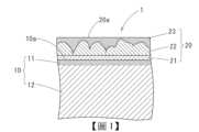
針對本發明之實施形態進行說明。此實施形態之附鍍敷被膜之銅合金板1係如圖1所示,於含有Zn及Sn、Ni、P、Fe之銅合金板10的表面10a,形成有依Cu層21、Sn-Cu合金層22及Sn層23順序層合而成之鍍敷被膜20。The embodiment of the present invention is described. The copper alloy plate 1 with a coating film in this embodiment is as shown in FIG. 1 , and a
[銅合金板]銅合金板10係在板厚方向的中心部,以質量%(以下之元素含有率亦相同)包含超過2.0%,且為32.5%以下之Zn、與0.1%以上0.9%以下之Sn、與0.05%以上且未滿1.0%之Ni、與0.001%以上且未滿0.1%之Fe、與0.005%以上0.1%以下之P,且殘部為包含Cu及不可避免的雜質而成。[Copper alloy plate]The
(Zn)Zn(鋅)係於本發明在作為對象之銅合金(黃銅),基本的合金元素,對銅合金板10的強度及彈性的提昇有效之元素。且由於Zn較Cu更便宜,故對銅合金板10之材料成本的減低亦有效果。Zn濃度為2.0%以下時,無法充分得到材料成本的減低效果。又,強度及彈性的提昇效果並不充分。另一方面,若Zn濃度超過32.5%,導致降低耐應力緩和特性,即使添加Fe、Ni、P,確保充分之耐應力緩和特性變困難,且降低耐腐蝕性,並且由於多量產生β相,亦導致降低冷軋性及彎曲加工性。據此,Zn濃度定為超過2.0%且為32.5%以下的範圍內。尚,Zn濃度於上述的範圍內,較佳為4.0%以上32.5%以下的範圍內,更佳為8.0%以上32.0%以下的範圍內,特佳為8.0%以上27.0%以下的範圍內。(Zn)Zn (zinc) is a basic alloying element in the copper alloy (brass) that is the object of the present invention, and is an element that is effective in improving the strength and elasticity of the
此情況下,Zn濃度在板厚的中心部之Zn濃度(中心Zn濃度)雖為前述之超過2.0%且為32.5%以下,但表面10a之Zn濃度(表面Zn濃度)定為中心Zn濃度的60%以下(0%以上)。又,Zn濃度從表面面向板厚的中心,產生10質量%/μm以上1000質量%/μm以下之濃度梯度。In this case, although the Zn concentration in the center of the plate thickness (central Zn concentration) is more than 2.0% and less than 32.5% as mentioned above, the Zn concentration on the
此銅合金板10由於表面Zn濃度為中心Zn濃度的60%以下,故於表面10a難以產生氧化Zn,又,即使於之後實施鍍敷進行加熱處理的情況,亦可抑制於鍍敷被膜20中擴散Zn。據此,焊料潤濕性優異並且可防止鍍敷被膜20之剝離。Since the surface Zn concentration of the
從表面10a對抗氧化及鍍敷被膜20之Zn擴散抑制的點來看,若於表面10a含有Zn即可(表面Zn濃度為中心Zn濃度的0%)。然而,若表面Zn濃度為中心Zn濃度的60%以下,由於即使於表面亦賦予某種程度作為含有Zn之銅合金的特性,故較佳。更佳之表面Zn濃度係相對於中心Zn濃度為40%以下,再更佳為30%以下。From the viewpoint of the
從此表面10a往板厚方向所產生之Zn的濃度梯度未滿10質量%/μm時,直到達到相當的深度,才能達到所期望的Zn濃度,損害作為含有Zn之銅合金板的特性。另一方面,Zn的濃度梯度超過1000質量%/μm時,由於其濃度梯度所產生之部分(後述的表面部)變過薄,故抑制Zn之擴散的效果變貧乏。此Zn之濃度梯度較佳為20質量%/μm以上500質量%/μm以下,更佳為50質量%/μm以上200質量%/μm以下。When the Zn concentration gradient generated from the
尚,在此濃度梯度所產生之部分,將Zn濃度從成為中心Zn濃度的90%之深度位置至表面10a為止的範圍定為表層部11。此表層部11係厚度為0μm以上1μm以下,較佳為0.3μm以下,更佳為0.2μm以下。對於此表層部11,將較表層部11更內側的部分定為母材內部12。In the portion where the concentration gradient is generated, the range from the depth position where the Zn concentration becomes 90% of the central Zn concentration to the
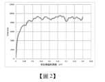
圖2係表示將銅合金板10於板厚方向進行薄膜化所得之試料,在X光光分子分光測定裝置(XPS),於深度方向分析Zn成分的結果之圖表,橫軸為來自表面10a之深度,縱軸為XPS之光譜強度。於母材板厚方向中心部所測定之Zn濃度已安定,將其最大值與最小值的算術平均定為「中心Zn濃度」,將從表面10a面向板厚方向的中心部變化之Zn濃度最初到達中心Zn濃度的90%的位置為止的(來自表面10a之)深度定為「表層部厚度」。FIG2 is a graph showing the results of analyzing the Zn component in the depth direction of a sample obtained by thinning a
(Sn、Ni、Fe、P)Sn(錫)的添加對銅合金板10的強度提昇有效果,且實施鍍Sn,將使用之電子・電氣機器材料的母材作為黃銅合金,添加Sn,對附鍍Sn之黃銅材之回收性的提昇變有利。進而,藉由本發明者等之研究發現若Sn與Ni及Fe共存,亦有助於銅合金板10之耐應力緩和特性的提昇。Sn未滿0.1%時,無法充分得到此等之效果,另一方面,若Sn超過0.9%,有導致熱加工性及冷軋性降低,於熱軋或冷軋產生破裂之虞,且亦導致導電率降低。(Sn, Ni, Fe, P)The addition of Sn (tin) is effective in improving the strength of the
因此,Sn的添加量定為0.1%以上0.9%以下的範圍內。尚,Sn濃度於上述的範圍內,尤其是以0.2%以上0.8%以下的範圍內較佳。Therefore, the amount of Sn added is set to be in the range of 0.1% to 0.9%. In addition, the Sn concentration is preferably in the above range, particularly in the range of 0.2% to 0.8%.
Ni(鎳)與Fe、P一起為在本發明,特徵性的添加元素,藉由對Cu-Zn-Sn合金添加適量之Ni,使Ni與Fe、P共存,可將[Ni、Fe]-P系析出物從母相(α相主體)析出。又,藉由使Ni與Fe、Co、P共存,可將[Ni、Fe、Co]-P系析出物從母相(α相主體)析出。Ni (nickel) is a characteristic additive element in the present invention together with Fe and P. By adding an appropriate amount of Ni to the Cu-Zn-Sn alloy, Ni, Fe and P coexist, and [Ni, Fe]-P system precipitates can be precipitated from the parent phase (α phase main body). In addition, by making Ni, Fe, Co and P coexist, [Ni, Fe, Co]-P system precipitates can be precipitated from the parent phase (α phase main body).
藉由存在此等之[Ni、Fe]-P系析出物或[Ni、Fe、Co]-P系析出物,並藉由於再結晶時釘扎晶粒邊界(grain boundary)的效果,可縮小母相之銅的平均結晶粒徑。其結果可增加銅合金板10的強度。且,藉由如此縮小平均結晶粒徑,亦可提昇彎曲加工性或耐應力腐蝕易裂性。進而,藉由此等之析出物的存在,可大幅提昇耐應力緩和特性。此外,藉由使Ni與Sn、Fe、Co(鈷)、P共存,不僅提昇藉由析出物之耐應力緩和特性,對藉由固溶強化之強度提昇亦有效果。於此,Ni的添加量未滿0.05%時,並無法充分提昇耐應力緩和特性。另一方面,若Ni的添加量為1.0%以上,固溶在母相之Ni變多,降低導電率,且因高價之Ni原材料的使用量增大而導致成本上昇。By the presence of such [Ni, Fe]-P precipitates or [Ni, Fe, Co]-P precipitates, and by the effect of nailing the grain boundary during recrystallization, the average crystal grain size of the copper of the parent phase can be reduced. As a result, the strength of the
因此,Ni的添加量定為0.05%以上且未滿1.0%的範圍內。尚,Ni的添加量於上述的範圍內,尤其是以成為0.05%以上且未滿0.8%的範圍內較佳。Therefore, the amount of Ni added is set to be in the range of 0.05% or more and less than 1.0%. In addition, the amount of Ni added is preferably in the above range, particularly in the range of 0.05% or more and less than 0.8%.
Fe(鐵)在本發明為特徵性的添加元素,藉由對Cu-Zn-Sn合金添加適量之Fe,使Fe與Ni、P共存,可使[Ni、Fe]-P系析出物從母相(α相主體)析出。又,藉由使Fe與Ni、Co、P共存,可使[Ni、Fe、Co]-P系析出物從母相(α相主體)析出。Fe (iron) is a characteristic additive element in the present invention. By adding an appropriate amount of Fe to the Cu-Zn-Sn alloy, Fe, Ni and P coexist, and [Ni, Fe]-P series precipitates can be precipitated from the parent phase (α phase main body). In addition, by making Fe, Ni, Co and P coexist, [Ni, Fe, Co]-P series precipitates can be precipitated from the parent phase (α phase main body).
藉由存在此等之[Ni,Fe]-P系析出物或[Ni、Fe、Co]-P系析出物,並藉由於再結晶時釘扎晶粒邊界之效果,可縮小銅的平均結晶粒徑,其結果可增加銅合金板10的強度。且藉由如此縮小平均結晶粒徑,亦可提昇彎曲加工性或耐應力腐蝕易裂性。進而,藉由此等之析出物的存在,可大幅提昇耐應力緩和特性。於此,Fe的添加量未滿0.001%時,並無法充分得到釘扎晶粒邊界之效果,因此,得不到充分的強度。另一方面,即使Fe的添加量定為0.10%以上,觀察不到強度的進一步提昇,固溶在母相之Fe變多,降低導電率,且亦導致冷軋性降低。By the presence of such [Ni,Fe]-P precipitates or [Ni,Fe,Co]-P precipitates, the average crystal grain size of copper can be reduced by the effect of pinning the grain boundary during recrystallization, and as a result, the strength of the
因此,Fe的添加量定為0.001%以上且未滿0.10%的範圍內。尚,Fe的添加量於上述的範圍內,尤其是以成為0.002%以上0.08%以下的範圍內較佳。Therefore, the amount of Fe added is set to be in the range of 0.001% or more and less than 0.10%. In addition, the amount of Fe added is preferably in the above range, particularly in the range of 0.002% or more and 0.08% or less.
P(磷)與Fe、Ni、進而與Co之結合性高,若與Fe、Ni一起含有適量之P,則可析出[Ni、Fe]-P系析出物。且,若與Fe、Ni、Co一起含有適量之P,則可析出[Ni、Fe、Co]-P系析出物。P (phosphorus) has a high bonding property with Fe, Ni, and further with Co. If an appropriate amount of P is contained together with Fe and Ni, [Ni, Fe]-P series precipitates can be precipitated. Also, if an appropriate amount of P is contained together with Fe, Ni, and Co, [Ni, Fe, Co]-P series precipitates can be precipitated.
藉由此等之析出物的存在,可提昇銅合金板10之耐應力緩和特性。於此,P的含量未滿0.005%時,充分析出[Ni、Fe]-P系析出物或[Ni、Fe、Co]-P系析出物變困難,變成無法充分提昇耐應力緩和特性。另一方面,若P的含量超過0.10%,對母相之P的固溶量變多,降低導電率,並且降低軋製性,導致容量產生冷軋破裂。The presence of such precipitates can improve the stress relaxation resistance of the
因此,P的含量定為0.005%以上0.10%以下的範圍內。尚,P的含量於上述的範圍內,尤其是以0.01%以上0.08%以下的範圍內較佳。Therefore, the content of P is set to be in the range of 0.005% to 0.10%. In addition, the content of P is preferably in the above range, particularly in the range of 0.01% to 0.08%.
尚,P係從銅合金之溶解原料不可避免混入為多之元素,據此,為了將P的含量如上述般規定,期望為適當選定溶解原料。However, P is an element that is inevitably mixed in a large amount from the molten raw materials of the copper alloy. Therefore, in order to define the P content as mentioned above, it is desirable to appropriately select the molten raw materials.
以上之各元素的殘部基本上若定為Cu(銅)及不可避免的雜質即可。於此,作為不可避免的雜質,雖可列舉Mg、Al、 Mn、Si、 (Co)、Cr、Ag、Ca、Sr、Ba、Sc、Y、Hf、V、Nb、Ta、Mo、W、Re、Ru、Os、Se、Te、Rh、Ir、Pd、Pt、Au、Cd、Ga、In、Li、Ge、As、Sb、Ti、Tl、Pb、Bi、S、O、C、Be、N、H、Hg、 B、Zr、稀土類等,但此等之不可避免的雜質以總量期望為0.3質量%以下。The residue of each of the above elements can basically be defined as Cu (copper) and inevitable impurities. Here, as inevitable impurities, although Mg, Al, Mn, Si, (Co), Cr, Ag, Ca, Sr, Ba, Sc, Y, Hf, V, Nb, Ta, Mo, W, Re, Ru, Os, Se, Te, Rh, Ir, Pd, Pt, Au, Cd, Ga, In, Li, Ge, As, Sb, Ti, Tl, Pb, Bi, S, O, C, Be, N, H, Hg, B, Zr, rare earth elements, etc. can be listed, but the total amount of these inevitable impurities is expected to be 0.3 mass% or less.
尚,其中,對於Co可故意含有0.001%以上且未滿0.10%。若將Co於此範圍與Ni、Fe、P一起添加,生成[Ni、Fe,Co]-P系析出物,可更一層提昇銅合金板10之耐應力緩和特性。於此,Co添加量未滿0.001%時,得不到藉由Co添加之耐應力緩和特性的更一層的提昇效果,另一方面,若Co添加量定為0.10%以上,則固溶Co變多降低導電率,且因高價之Co原材料之使用量的增大導致成本上昇。Among them, Co can be intentionally contained in an amount of 0.001% or more and less than 0.10%. If Co is added together with Ni, Fe, and P in this range, [Ni, Fe, Co]-P system precipitates are generated, and the stress relaxation characteristics of the
因此,添加Co時之Co的添加量定為0.001%以上且未滿0.10%的範圍內。尚,Co的添加量於上述的範圍內,尤其是以定為0.002%以上0.08%以下的範圍內較佳。尚,又,即使於未積極添加Co的情況,作為雜質,當然亦有含有未滿0.001%之Co的情況。Therefore, when Co is added, the amount of Co added is set to be within the range of 0.001% or more and less than 0.10%. In addition, the amount of Co added is preferably within the above range, particularly preferably within the range of 0.002% or more and 0.08% or less. In addition, even when Co is not actively added, Co may be contained as an impurity in an amount of less than 0.001%.
[鍍敷被膜]鍍敷被膜20係從銅合金板10的表面10a,施加在鍍敷被膜20的表面20a,依厚度為0μm~1μm之Cu層21、厚度為0.1μm~1.5μm之Sn-Cu合金層22、厚度為0.1μm~3.0μm之Sn層23的順序構成而成。[Plating film]The
Cu層21的厚度超過1μm時,有於加熱時發生在鍍敷被膜層內部之熱應力變高,產生鍍敷被膜20的剝離之虞。亦有不存在此Cu層21的情況。When the thickness of the
Sn-Cu合金層22為硬質,其厚度未滿0.1μm時,作為連接器之使用時之插入力的減低效果變薄,並降低強度。Sn-Cu合金層22的厚度超過1.5μm時,有於加熱時發生在鍍敷被膜20之熱應力變高,產生鍍敷被膜20的剝離之虞。The Sn-
Sn層23的厚度未滿0.1μm時,焊料潤濕性降低,且厚度超過3.0μm時,有於加熱時發生在鍍敷被膜20內部之熱應力變高之虞。When the thickness of the
包含以上之層構成而成之鍍敷被膜20中之Zn的平均濃度為銅合金板10的中心Zn濃度的10%以下(0%以上)。The average Zn concentration in the
鍍敷被膜20中之Zn的平均濃度超過銅合金板10的中心Zn濃度的10%時,有鍍敷被膜中之Zn擴散至表面20a,減低焊料潤濕性之虞。鍍敷被膜20中之Zn的平均濃度更佳為銅合金板10的中心Zn濃度的5%以下,再更佳為3%以下。When the average Zn concentration in the
[製造方法]針對製造如以上般構成之附鍍敷被膜的銅合金板1之方法進行說明。[Manufacturing method]The method for manufacturing the copper alloy plate 1 with a coating having the above-mentioned structure is described.
此附鍍敷被膜之銅合金板1係藉由以下步驟製造,銅合金用母材製造步驟係製造具有:包含超過2.0%且為32.5%以下之Zn、0.1%以上0.9%以下之Sn、0.05%以上且未滿1.0%之Ni、0.001%以上且未滿0.1%之Fe、0.005%以上0.1%以下之P,殘部為Cu及不可避免的雜質之組成的銅合金母材(銅合金用母材製造步驟)、於所得之銅合金母材實施表面處理(表面處理步驟)後,進行鍍敷處理(鍍敷處理步驟),並進行回流處理(回流處理步驟)。The copper alloy plate 1 with a coating is manufactured by the following steps: the copper alloy base material manufacturing step is to manufacture a copper alloy base material having a composition containing more than 2.0% and less than 32.5% Zn, more than 0.1% and less than 0.9% Sn, more than 0.05% and less than 1.0% Ni, more than 0.001% and less than 0.1% Fe, more than 0.005% and less than 0.1% P, and the remainder is Cu and inevitable impurities (copper alloy base material manufacturing step), after surface treatment (surface treatment step) is performed on the obtained copper alloy base material, plating treatment (plating treatment step), and reflow treatment (reflow treatment step).
(銅合金母材製造步驟)銅合金母材係將調合在上述之成分範圍的材料藉由溶解鑄造,製作銅合金鑄塊,將此銅合金鑄塊經由包含熱軋、冷軋、連續退火、精冷軋順序之步驟製造。於本實施例,將銅合金母材的板厚定為0.2mm。(Copper alloy base material manufacturing steps)The copper alloy base material is prepared by melting and casting the materials blended within the above-mentioned composition range to produce a copper alloy ingot, which is manufactured through steps including hot rolling, cold rolling, continuous annealing, and fine cold rolling. In this embodiment, the plate thickness of the copper alloy base material is set to 0.2 mm.
(表面處理步驟)於所得之銅合金母材實施表面處理。此表面處理係具有使銅合金母材中之Zn擴散至表面部,並進行濃化之Zn濃化處理、與去除濃化Zn的表面部之表面部去除處理。(Surface treatment step) The obtained copper alloy base material is subjected to surface treatment. This surface treatment includes Zn concentration treatment for diffusing Zn in the copper alloy base material to the surface and concentrating it, and surface removal treatment for removing the surface portion where Zn is concentrated.
作為Zn濃化處理,將銅合金母材於氧或臭氧等之氧化性環境下指定時間加熱至指定溫度。此時之加熱溫度、加熱時間若於100℃以上且於不產生再結晶的時間內實施即可,從其中,以考量設備限制或經濟性等之任意溫度實施即可。例如,於300℃為1分鐘,於250℃為2小時,或於200℃為5小時等,若為低溫則長時間,若為高溫則短時間即可。As a Zn enrichment treatment, the copper alloy base material is heated to a specified temperature for a specified time in an oxidizing environment such as oxygen or ozone. The heating temperature and heating time at this time can be implemented as long as it is above 100°C and within the time when recrystallization does not occur. From among them, it can be implemented at any temperature considering equipment limitations or economy. For example, it can be implemented at 300°C for 1 minute, at 250°C for 2 hours, or at 200°C for 5 hours. If it is a low temperature, it can be a long time, and if it is a high temperature, it can be a short time.
氧化性環境之氧化性物質濃度,例如若為臭氧則為5~4000ppm即可,期望為10~2000ppm,更期望為20~1000ppm即可。不使用臭氧而使用氧時,期望為相對於僅使用臭氧時,為2倍以上之環境濃度。可混合臭氧等氧化性物質與氧使用。尚,於Zn濃化處理之前,可實施藉由機械研磨等之應變或空孔的導入等用以促進Zn的擴散之處理。The concentration of the oxidizing substance in the oxidizing environment, for example, in the case of ozone, can be 5 to 4000 ppm, preferably 10 to 2000 ppm, and more preferably 20 to 1000 ppm. When oxygen is used instead of ozone, the concentration of the environment is preferably twice or more of that when only ozone is used. Oxidizing substances such as ozone and oxygen may be mixed for use. In addition, before the Zn concentration treatment, a treatment for promoting the diffusion of Zn by strain such as mechanical grinding or introduction of pores may be performed.
作為表面部去除處理,可藉由對實施Zn濃化處理之銅合金母材,適用單獨或複數組合化學研磨、電解研磨、機械研磨等來進行。As a surface removal treatment, it can be carried out by applying chemical polishing, electrolytic polishing, mechanical polishing, etc. alone or in combination to the copper alloy base material that has been subjected to Zn enrichment treatment.
化學研磨可使用選擇性蝕刻等。選擇性蝕刻可使用蝕刻等,該蝕刻係使用例如包含非離子性界面活性劑、具有羰基或羧基之雜環式化合物、咪唑化合物、三唑化合物、四唑化合物等之可抑制銅腐蝕的成分之酸性或鹼性的液體。Chemical polishing may use selective etching, etc. Selective etching may use etching, etc. The etching uses an acidic or alkaline liquid containing a component that can inhibit copper corrosion, such as a non-ionic surfactant, a heterocyclic compound having a carbonyl group or a carboxyl group, an imidazole compound, a triazole compound, a tetrazole compound, etc.
電解研磨可使用例如將酸或鹼性的液體作為電解液使用,且對於易偏析在銅之晶粒邊界的成分之藉由電解的晶粒邊界之優先性蝕刻等。Electrolytic polishing can use, for example, an acid or alkaline liquid as an electrolyte, and can preferentially etch the grain boundaries of components that are easily segregated at the grain boundaries of copper by electrolysis.
機械研磨可使用噴砂處理、研光(Lapping)處理、拋光(Polishing)處理、磨光(buffing)、砂輪機研磨、砂紙研磨等之一般所使用之各種方法。Mechanical grinding can use various commonly used methods such as sandblasting, lapping, polishing, buffing, grinding with a grinder, and sandpaper grinding.
如此進行,藉由對銅合金母材進行Zn濃化處理及表面部去除處理,形成銅合金板10。銅合金板10如前述,表層部11的Zn濃度與中心Zn濃度相比較較低,又,成為從表面10a面向板厚方向的中心部,以指定的濃度梯度增加Zn濃度的狀態。In this way, the copper alloy base material is subjected to Zn concentration treatment and surface removal treatment to form the
(鍍敷處理步驟)接著,於此銅合金板10的表面10a為了形成鍍敷被膜20,而進行鍍敷處理。(Plating treatment step)Next, a plating treatment is performed on the
藉由對銅合金板10的表面10a進行脫脂、酸洗等之處理,去除污垢與自然氧化膜,清淨表面後,並於其上實施鍍Cu處理,而形成鍍Cu層,接著,對鍍Cu層的表面實施鍍Sn處理,而形成鍍Sn層。尚,上述鍍Cu層及鍍Sn層雖期望分別成為純銅及純錫的鍍敷層,但若為不損害本發明之作用效果的範圍,可作為分別包含其他元素之Cu合金鍍敷層及Sn合金鍍敷層。The
各鍍敷層係以電流密度0.1A/dm2以上60A/dm2以下之電解鍍敷形成。電解鍍敷時之電流密度未滿0.1A/dm2時,成膜速度遲緩並不經濟。電流密度超過60A/dm2時,超過擴散極限電流密度,無法形成無缺陷之被膜。Each coating layer is formed by electrolytic plating at a current density of 0.1A/dm2 or more and 60A/dm2 or less. When the current density during electrolytic plating is less than 0.1A/dm2 , the film forming speed is slow and uneconomical. When the current density exceeds 60A/dm2 , it exceeds the diffusion limit current density and a defect-free film cannot be formed.
將藉由Cu或Cu合金之鍍敷處理條件的一例示於表1,將藉由Sn或Sn合金之鍍敷處理條件的一例示於表2。Table 1 shows an example of plating treatment conditions using Cu or a Cu alloy, and Table 2 shows an example of plating treatment conditions using Sn or a Sn alloy.
(回流處理步驟)接著,對於形成此等之鍍敷層的銅合金板10,以加熱峰值溫度230℃以上330℃以下,保持在其加熱峰值溫度0.5秒以上30秒以下後,實施冷卻至60℃以下之溫度為止的回流處理。(Reflow treatment step)Then, the
藉由實施此回流處理,從銅合金板10的表面10a,形成依厚度為0μm~1μm之Cu層21、厚度為0.1μm~1.5μm之Sn-Cu合金層22、厚度為0.1μm~3.0μm之Sn層23的順序構成之鍍敷被膜20。尚,在此回流處理,亦有鍍Cu層之Cu的全部與鍍Sn層之Sn進行合金化,未形成Cu層21的情況。By performing this reflow treatment, a plated
藉由此回流處理,有銅合金板10的表面10a的一部分之Cu擴散至鍍敷被膜20,與構成鍍敷被膜20之Sn進行合金化的可能性,該情況下,雖亦幼有含有在銅合金板10之Zn或Cu皆擴散至鍍敷被膜20的可能性,但由於低銅合金板10的表面10a的Zn濃度形成,取入到鍍敷被膜20中的Zn亦足夠小,故可有效果地抑制Zn的表面擴散。By this reflow treatment, there is a possibility that Cu on a portion of the
又,由於銅合金板10的表面係Zn極為少,表面氧化物亦少,即使些微存在氧化物,可藉由鍍敷處理前之通常的洗淨等輕易去除。據此,此附鍍敷被膜之銅合金板1係鍍敷被膜20與銅合金板10的密著性亦優異。Furthermore, since the surface of the
進而,由於在鍍敷被膜20的表面20a亦難以產生氧化Zn,故亦成為鍍敷被膜20之焊料潤濕性優異者。Furthermore, since Zn oxide is difficult to be generated on the
尚,於上述實施形態,雖於銅合金板10形成依Cu層21、Sn-Cu合金層22、Sn層23的順序構成之鍍敷被膜20,鍍敷被膜並非被限定於此,若為由錫、銅、鋅、鎳、金、銀、鈀及該等之合金當中選出之1個以上之層所構成者即可。實施例In the above-mentioned embodiment, although the
[實施例1]準備包含超過2.0%且為32.5%以下之Zn、0.1%以上0.9%以下之Sn、0.05%以上且未滿1.0%之Ni、0.001%以上且未滿0.1%之Fe、0.005%以上0.1%以下之P,殘部為包含Cu及不可避免的雜質而成之銅合金的鑄塊,藉由常法經由熱軋、中間退火、冷軋等,製作板狀之銅合金母板。於一部分之鑄塊進一步含有0.001%以上且未滿0.1%之Co。[Example 1]Prepare a copper alloy ingot containing more than 2.0% and less than 32.5% Zn, more than 0.1% and less than 0.9% Sn, more than 0.05% and less than 1.0% Ni, more than 0.001% and less than 0.1% Fe, more than 0.005% and less than 0.1% P, and the remainder containing Cu and inevitable impurities, and make a copper alloy mother plate in the form of a plate by hot rolling, intermediate annealing, cold rolling, etc. in a conventional method. A portion of the ingot further contains more than 0.001% and less than 0.1% Co.
接著,對於此銅合金母板,藉由於氧化性環境下於加熱溫度200~300℃、加熱時間1分鐘~5小時的範圍內變更各種條件進行加熱,實施Zn濃化處理後,並藉由進行表面部去除處理,製作於表層部具有各種Zn濃度梯度之銅合金板。Next, the copper alloy mother plate is heated under various conditions in an oxidizing environment at a heating temperature of 200 to 300°C and a heating time of 1 minute to 5 hours, and a Zn concentration treatment is performed. Then, a surface removal treatment is performed to produce a copper alloy plate having various Zn concentration gradients on the surface.
表面部去除處理係進行以下之研磨處理的任一種。物理研磨:磨光(buffing)化學研磨:浸漬在對硫酸與過氧化氫混合水溶液添加聚氧乙烯十二烷基醚之研磨液電解研磨:於磷酸水溶液使用SUS304作為對極來通電作為比較例,亦製作未實施Zn濃化處理及表面部去除處理之試料(直接是銅合金母板之試料)。Surface removal treatment is any of the following polishing treatments.Physical polishing: buffingChemical polishing: immersion in a polishing liquid containing polyoxyethylene lauryl ether added to a mixed aqueous solution of sulfuric acid and hydrogen peroxideElectrolytic polishing: using SUS304 as a counter electrode to pass electricity in a phosphoric acid aqueous solutionAs a comparative example, a sample (a sample directly made of a copper alloy motherboard) without Zn enrichment treatment and surface removal treatment was also prepared.
而且,測定在此等各銅合金板的表面及板厚方向之各部的Zn濃度。針對板厚方向之各部的Zn濃度,由在X光光電子分光法(XPS)之深度方向的濃度分佈測定。XPS的測定條件係如下述。Furthermore, the Zn concentration on the surface and in each part in the thickness direction of each copper alloy plate was measured.The Zn concentration in each part in the thickness direction was measured by the concentration distribution in the depth direction by X-ray photoelectron spectroscopy (XPS). The measurement conditions of XPS are as follows.
(測定條件)前處理:浸漬在丙酮溶劑中,並使用超音波洗淨機,進行38kHz 5分鐘前處理。使用之裝置: ULVAC PHI股份有限公司製X線光電子分光分析裝置PHI5000 VersaProbe濺鍍速率:100Å/min濺鍍時間:100分鐘(Measurement conditions)Pretreatment: Immerse in acetone solvent and use an ultrasonic cleaner for 5 minutes at 38kHz.Device used: ULVAC PHI Co., Ltd.X-ray photoelectron spectrometer PHI5000 VersaProbeSputtering rate: 100Å/minSputtering time: 100 minutes
尚,由於在上述之XPS的深度為SiO2換算深度,藉由與藉由來自另一剖面方向之TEM-EDX(能量分散型X光分光法Energy Dispersive X-ray Spectroscopy)所測定之數據進行比較,將在XPS深度方向濃度分佈之SiO2換算深度換算成實深度。Furthermore, since the XPS depth mentioned above is the SiO2-converted depth,the SiO2- converted depth of the concentration distribution in the XPS depth direction is converted into the actual depth by comparing it with the data measured by TEM-EDX (Energy Dispersive X- ray Spectroscopy) from another cross-sectional direction.
銅合金板的中心Zn濃度係採取Zn濃度安定中之厚度中心部分,在高頻率感應耦合電漿發光分光分析法(ICP-AES)測定。The central Zn concentration of the copper alloy plate was measured by high frequency inductively coupled plasma emission spectrometry (ICP-AES) at the central part of the thickness where the Zn concentration was stable.
接著,對各銅合金板進行用以去除污垢與自然氧化膜之脫脂、酸洗等之處理後,以表1所示之鍍Cu條件形成鍍Cu層,接著,以表2所示之鍍Sn條件形成鍍Sn層,回流處理形成此等之鍍敷層的銅合金板,製作附鍍敷被膜之銅合金板。Next, each copper alloy plate was subjected to degreasing and pickling treatments to remove dirt and natural oxide films, and then a Cu layer was formed under the Cu plating conditions shown in Table 1. Then, a Sn layer was formed under the Sn plating conditions shown in Table 2. The copper alloy plates with these plated layers were reflow treated to produce copper alloy plates with plated coatings.
回流處理係將鍍敷層加熱至230℃以上330℃以下的範圍內的溫度後,再冷卻至60℃以下的溫度為止。The reflow treatment is to heat the coating layer to a temperature within a range of 230°C to 330°C and then cool it to a temperature below 60°C.
而且,從各附鍍敷被膜之銅合金板切出試料,測定鍍敷被膜中之Zn濃度。對於鍍敷被膜之Zn濃度的測定與上述之銅合金板的情況相同,係由來自藉由XPS之表面之深度方向的濃度分佈求出。Furthermore, samples were cut out from each copper alloy plate with a coating, and the Zn concentration in the coating was measured.The Zn concentration in the coating was measured in the same manner as in the copper alloy plate described above, and was obtained from the concentration distribution in the depth direction from the surface by XPS.
又,對於各銅合金板之裸材料(未形成鍍敷被膜之銅合金板)及附鍍敷被膜之銅合金板的各試料,測定表面之焊料潤濕性,並且測定對於裸材料(銅合金板)的表面硬度,及附鍍敷被膜之銅合金板之鍍敷被膜的密著性。In addition, for each sample of the bare copper alloy plate (copper alloy plate without a coating) and the copper alloy plate with a coating, the solder wettability of the surface was measured, and the surface hardness of the bare copper alloy plate and the adhesion of the coating of the copper alloy plate with a coating were measured.
<焊料潤濕性>焊料潤濕性係依照JIS-C60068-2-54之焊接試驗方法(平衡法),使用RHESCA股份有限公司5200TN焊料檢查器,以脫脂去除污垢後,在下述之焊劑塗佈、焊接條件,評估各試料與無鉛焊料的潤濕性。<Solder Wettability>The solder wettability is based on the soldering test method (balance method) of JIS-C60068-2-54. After degreasing and removing dirt, the wettability of each sample and lead-free solder is evaluated under the following solder coating and soldering conditions using the 5200TN solder tester of RHESCA Co., Ltd.
(焊劑塗佈)焊劑:25%松香-乙醇焊劑溫度:室溫焊劑深度:8mm焊劑浸漬時間:5秒切碎方法:將邊緣放在濾紙5秒,去除焊劑,並固定在裝置保持30秒(Solder coating)Solder: 25% rosin-ethanolSolder temperature: room temperatureSolder depth: 8mmSolder immersion time: 5 secondsChopping method: Place the edge on the filter paper for 5 seconds, remove the solder, and fix it in the device for 30 seconds
(焊接)焊料組成:千住金屬工業股份有限公司製Sn-3.0%Ag-0.5%Cu焊料溫度:240℃焊料浸漬速度:10±2.5mm/秒焊料浸漬深度:2mm焊料浸漬時間:10秒(Soldering)Solder composition: Sn-3.0%Ag-0.5%Cu manufactured by Senju Metal Industries Co., Ltd.Solder temperature: 240°CSolder immersion speed: 10±2.5mm/secSolder immersion depth: 2mmSolder immersion time: 10 sec
藉由所得之荷重/時間曲線,將從浸漬開始至藉由表面張力之浮力成為零(亦即焊料與試料的接觸角為90°)為止的時間定為零交叉時間(秒)。焊料潤濕性係將零交叉時間未滿2秒者定為A(良),2秒以上且未滿4秒者定為B(可),4秒以上者定為C(不可)。The load/time curve obtained is used to define the time from the start of immersion to the time when the buoyancy due to surface tension becomes zero (i.e., the contact angle between the solder and the sample is 90°) as the zero crossing time (seconds). For solder wettability, a zero crossing time of less than 2 seconds is rated as A (good), a zero crossing time of more than 2 seconds but less than 4 seconds is rated as B (acceptable), and a zero crossing time of more than 4 seconds is rated as C (unacceptable).
<密著性>密著性係對120℃、加熱1000小時之試料,以橫切試驗評估。以切刀對試料作出切口,製作100個1mm平方之方格後,用指壓將玻璃紙膠帶(NICHIBAN股份有限公司製#405)壓在方格,剝離該玻璃紙膠帶後,將未發生鍍敷被膜的剝離的情況定為A,將經剝離之方格為3個以下的情況定為B,將方格剝離4個以上的情況定為C。<Adhesion>Adhesion is evaluated by cross-section test on the sample heated at 120℃ for 1000 hours. The sample is cut with a cutter to make 100 1mm square grids, and then a cellophane tape (#405 manufactured by NICHIBAN Co., Ltd.) is pressed on the grids with finger pressure. After peeling off the cellophane tape, the case where no peeling of the coating film occurs is rated as A, the case where less than 3 squares are peeled is rated as B, and the case where more than 4 squares are peeled is rated as C.
<表面硬度>表面硬度係將未形成鍍敷被膜之裸材料(銅合金板)作為測定對象。使用維氏硬度計,測定荷重1gf與在10gf之硬度,將以荷重1gf計測之硬度為以荷重10gf計測之硬度的80%以上者定為A(良),將70%以上且未滿80%者定為B(可),將未滿70%者定為C(不可)。<Surface hardness>Surface hardness is measured on bare materials (copper alloy plates) without coating. Using a Vickers hardness tester, the hardness at a load of 1 gf and 10 gf is measured. A (good) is given when the hardness measured at a load of 1 gf is 80% or more of the hardness measured at a load of 10 gf, B (acceptable) is given when the hardness is 70% or more but less than 80%, and C (unacceptable) is given when the hardness is less than 70%.
於表3A、3B及表4A、4B、4C表示在各裸材料(銅合金板)之試料的評估結果,於表5A、5B及表6A、6B、6C表示在各附鍍敷被膜之銅合金板之試料的評估結果。Tables 3A, 3B and Tables 4A, 4B, and 4C show the evaluation results of the samples of the bare materials (copper alloy plates), and Tables 5A, 5B and Tables 6A, 6B, and 6C show the evaluation results of the samples of the copper alloy plates with coatings.
在任一表中,「中心Zn濃度」為在板厚的中心部之Zn濃度,「中心Sn、Ni、Fe、P、Co濃度」為在板厚的中心部之Sn、Ni、Fe、P、Co的濃度,「表面Zn濃度」為於進行表面部去除處理之階段的銅合金板表面的Zn濃度,單位為質量%。「對中心濃度比」係相對於表面Zn濃度的中心Zn濃度之比率,且單位為%。「表層部厚度」係從銅合金板的表面Zn濃度首次到達中心Zn濃度的90%為止的深度,且單位為μm,「濃度梯度」為在表層部之Zn濃度的梯度,且單位為質量%/μm。In any table, "Center Zn concentration" is the Zn concentration in the center of the plate thickness, "Center Sn, Ni, Fe, P, Co concentration" is the concentration of Sn, Ni, Fe, P, Co in the center of the plate thickness, "Surface Zn concentration" is the Zn concentration on the surface of the copper alloy plate at the stage of surface removal treatment, and the unit is mass %. "Center concentration ratio" is the ratio of the center Zn concentration to the surface Zn concentration, and the unit is %. "Surface thickness" is the depth from the surface Zn concentration of the copper alloy plate to the first time it reaches 90% of the center Zn concentration, and the unit is μm, and "Concentration gradient" is the gradient of Zn concentration in the surface, and the unit is mass %/μm.
此表層部厚度及濃度梯度係由藉由XPS之Zn成分的深度方向濃度分佈算出。圖2為其分佈之一例,係關於表4的中心Zn濃度為10質量%,濃度梯度為130質量%/μm之樣品者。包含此例,於表3及表4之各試料,製作各種的表面Zn濃度的銅合金板。又,於表5及表6之各試料,於表3及表4之各銅合金板形成鍍敷被膜。The surface thickness and concentration gradient are calculated from the depth-direction concentration distribution of the Zn component by XPS. Figure 2 shows an example of the distribution, which is for a sample with a central Zn concentration of 10 mass% and a concentration gradient of 130 mass%/μm in Table 4. Including this example, copper alloy plates with various surface Zn concentrations were prepared for each sample in Tables 3 and 4. In addition, for each sample in Tables 5 and 6, a coating was formed on each copper alloy plate in Tables 3 and 4.
濃度梯度係意指連接在分佈之表面的濃度、與首次達到板厚中心部濃度的90%的點之直線梯度。亦即,在深度方向濃度分佈,從銅合金板的表面,首次達到板厚中心部濃度的90%的點為止的Zn濃度變化,即使有局部性變動,大致上視為一定梯度的直線時,將其分佈的梯度定為濃度梯度。Concentration gradient refers to the gradient of a straight line connecting the concentration on the surface of the distribution and the point where the concentration first reaches 90% of the center of the plate thickness. In other words, in the depth direction, the Zn concentration change from the surface of the copper alloy plate to the point where the concentration first reaches 90% of the center of the plate thickness, even if there are local changes, is generally regarded as a straight line with a constant gradient, and the gradient of the distribution is defined as the concentration gradient.
各表總結每個中心Zn濃度,中心Zn濃度係表3A為2.1質量%,表3B為10質量%,表4A為20質量%,表4B為32.5質量%,表4C為20質量%,表5A為2.1質量%,表5B為10質量%,表6A為20質量%,表6B為32.5質量%,表6C為2.1質量%。Each table summarizes the Zn concentration at each center. The Zn concentration at the center is 2.1 mass % for Table 3A, 10 mass % for Table 3B, 20 mass % for Table 4A, 32.5 mass % for Table 4B, 20 mass % for Table 4C, 2.1 mass % for Table 5A, 10 mass % for Table 5B, 20 mass % for Table 6A, 32.5 mass % for Table 6B, and 2.1 mass % for Table 6C.
尚,在表5A、5B及表6A、6B、6C,鍍Cu層的厚度的單位為μm,鍍Cu層的厚度為「0」,係未實施鍍Cu,且僅進行鍍Sn處理之例。鍍Sn層的厚度定為1μm。In Tables 5A, 5B and 6A, 6B, and 6C, the unit of the thickness of the Cu-plated layer is μm. The thickness of the Cu-plated layer is "0", which is an example in which Cu plating is not performed and only Sn plating is performed. The thickness of the Sn-plated layer is set to 1 μm.
如此表3及表4所示,對於銅合金板,未實施Zn濃化處理及表面部去除處理者(濃度梯度成為「∞(未處理)」,來自板表面之Zn濃度梯度極為緊急的狀態),及Zn濃度梯度超過1000質量%/μm者,係焊料潤濕性不良。對於表面硬度,在中心Zn濃度為20質量%之材料,於Zn濃度梯度未滿10質量%/μm者,係表面的硬度降低顯著。As shown in Tables 3 and 4, for copper alloy plates, those that have not been subjected to Zn concentration treatment and surface removal treatment (concentration gradient becomes "∞ (untreated)", a state in which the Zn concentration gradient from the plate surface is extremely critical) and those with a Zn concentration gradient exceeding 1000 mass%/μm have poor solder wettability. Regarding surface hardness, for materials with a Zn concentration of 20 mass% in the center, the surface hardness is significantly reduced when the Zn concentration gradient is less than 10 mass%/μm.
又,如表5及表6所示,對於銅合金板,未實施Zn濃化處理及表面部去除處理者(濃度梯度成為「∞(未處理)」,來自板表面之Zn濃度梯度極為緊急的狀態),及Zn濃度梯度超過1000質量%/μm者,即使形成鍍敷被膜,密著性亦不佳。Furthermore, as shown in Tables 5 and 6, for copper alloy plates that have not been subjected to Zn concentration treatment and surface removal treatment (the concentration gradient becomes "∞ (untreated)", and the Zn concentration gradient from the plate surface is in an extremely critical state), and for those with a Zn concentration gradient exceeding 1000 mass %/μm, even if a coating is formed, the adhesion is poor.
[實施例2]以與實施例1相同的方法,對中心Zn濃度32.5質量%的材料,製作具有各種濃度梯度之銅合金板後,以與實施例1相同的方法進行鍍敷,來製作附鍍敷被膜之銅合金板。[Example 2]The same method as in Example 1 was used to prepare copper alloy plates with various concentration gradients from a material having a central Zn concentration of 32.5 mass %, and then plated in the same method as in Example 1 to prepare copper alloy plates with a coating.
確認經製作之附鍍敷被膜之銅合金板的鍍Sn層中之Zn濃度及焊料潤濕性。鍍Sn層中之Zn濃度以與實施例1相同的條件在XPS測定。將結果示於表7。The Zn concentration in the Sn-plated layer of the produced copper alloy plate with a coating and the solder wettability were confirmed. The Zn concentration in the Sn-plated layer was measured by XPS under the same conditions as in Example 1. The results are shown in Table 7.
如表7所示,於濃度梯度超過1000質量%/μm之試料,鍍敷內Zn之對中心濃度比超過10%,並且焊料潤濕性惡化。As shown in Table 7, for samples with a concentration gradient exceeding 1000 mass%/μm, the Zn concentration ratio in the deposited layer to the center exceeded 10%, and the solder wettability deteriorated.
[實施例3]以與實施例1相同的方法,製作中心Zn濃度20質量%、濃度梯度10質量%/μm之銅合金板的試料。製作時,藉由使在表面部去除處理之去除量變量,濃度梯度雖相同,但定為表面Zn濃度不同之試料。於經製作之試料以與實施例1相同的方法,進行鍍敷處理,製作附鍍敷被膜之銅合金板,測定鍍敷密著性及焊料潤濕性。將結果示於表8。[Example 3]A sample of a copper alloy plate with a central Zn concentration of 20 mass% and a concentration gradient of 10 mass%/μm was prepared in the same manner as in Example 1. During the preparation, the amount of removal in the surface removal treatment was varied, so that the samples with different surface Zn concentrations were determined although the concentration gradient was the same. The prepared samples were plated in the same manner as in Example 1 to produce a copper alloy plate with a coating, and the plating adhesion and solder wettability were measured. The results are shown in Table 8.
如表8所示,於表面Zn濃度超過中心之Zn濃度的60%之試料,鍍敷密著性或焊料潤濕性惡化。As shown in Table 8, for samples where the Zn concentration on the surface exceeds 60% of the Zn concentration in the center, the plating adhesion or solder wettability deteriorates.
[實施例4]以與實施例1相同的方法,製作銅合金板之板厚中心部的Zn濃度(中心Zn濃度)32.5質量%且於表層部具有各種Zn濃度梯度,表面Zn濃度調整為0質量%之銅合金板(裸材料)後,形成僅1層表9所示之各種金屬鍍敷層。本實施例僅實施鍍敷處理,並未進行回流處理。[Example 4]In the same manner as in Example 1, a copper alloy plate (bare material) was prepared with a Zn concentration of 32.5 mass % in the center of the plate thickness (central Zn concentration) and various Zn concentration gradients in the surface layer, and the surface Zn concentration was adjusted to 0 mass %, and then only one layer of various metal plating layers shown in Table 9 was formed. This example only performed plating treatment and did not perform reflow treatment.
鍍敷之金屬種定為Sn、Cu、Zn、Ni、Au、Ag、Pd。鍍敷電流密度全部為3A/dm2,且鍍敷被膜的厚度定為1μm。尚,各種鍍敷浴雖可使用一般所使用之酸性、中性、鹼性浴之任一種,但於本實施例,Sn、Cu、Zn、Ni、Pd使用酸性浴,Au、Ag使用鹼性浴。The metal species to be plated are Sn, Cu, Zn, Ni, Au, Ag, and Pd. The plating current density is 3A/dm2 for all, and the thickness of the plated film is 1μm. In addition, the various plating baths can be any of the generally used acidic, neutral, and alkaline baths, but in this embodiment, an acidic bath is used for Sn, Cu, Zn, Ni, and Pd, and an alkaline bath is used for Au and Ag.
評估以上述順序製作之試料的焊料潤濕性、鍍敷被膜的密著性。評估方法及判定方法係與實施例1相同。將其評估結果示於表9。The solder wettability and adhesion of the coating film of the samples prepared in the above order were evaluated. The evaluation method and judgment method were the same as those in Example 1. The evaluation results are shown in Table 9.
如此表9所示,實施例、比較例焊料潤濕性雖皆良好,但如於比較例,未實施Zn濃化處理及表面部去除處理之試料(濃度梯度為「∞(未處理)」者),及Zn濃度梯度超過1000質量%/μm之試料,於加熱後發生鍍敷被膜的剝離。As shown in Table 9, although the solder wettability of the embodiment and the comparative example is good, in the comparative example, the sample that has not been subjected to Zn concentration treatment and surface removal treatment (concentration gradient is "∞ (untreated)") and the sample whose Zn concentration gradient exceeds 1000 mass %/μm, the coating film peels off after heating.
尚,於實施例,雖為僅1層之鍍敷被膜,但並非限制實施形態者,將成本減低或特性的進一步提昇等作為目的,可藉由加熱等之處理合金化各種金屬,或可成為多層之鍍敷被膜構造。In the embodiment, although there is only one layer of coating, this does not limit the implementation form. For the purpose of reducing costs or further improving characteristics, various metals can be alloyed by heating or the like, or a multi-layer coating structure can be formed.
例如,在上述之鍍Cu層與鍍Sn層的組合,由於某些特性上的原因,而無法實施回流處理時,於純鍍錫層,有在基底之銅(銅合金板或鍍Cu層)之間,隨著時間推移形成意外的合金層的情況,因起因於該合金層之鍍敷層的內部應力等之要因,有發生晶須之虞。該情況下,為了抑制晶須,亦可將鍍Sn層成為Sn與Cu或Ag等的合金鍍敷層。又,為了防止銅合金板之銅擴散至鍍敷層(例如錫層),且進行合金形成,亦可形成抑制擴散之中間層(例如電解鎳鍍敷層)。產業上之可利用性For example, when the combination of the above-mentioned Cu-plated layer and the Sn-plated layer cannot be reflowed due to some characteristics, an alloy layer may be formed unexpectedly over time between the pure Sn-plated layer and the underlying copper (copper alloy plate or Cu-plated layer), and whiskers may be generated due to factors such as internal stress of the plated layer of the alloy layer. In this case, in order to suppress whiskers, the Sn-plated layer may be an alloy-plated layer of Sn and Cu or Ag. In addition, in order to prevent the copper of the copper alloy plate from diffusing into the coating layer (such as the tin layer) and to perform alloy formation, an intermediate layer (such as an electrolytic nickel coating layer) that inhibits diffusion may also be formed.Industrial applicability
抑制表面的氧化,並且使電氣性連接信賴性提昇,且即使形成鍍敷被膜的情況,亦使鍍敷被膜中之Zn濃度減低,可實現鍍敷被膜表面之接觸電氣電阻的減低及鍍敷被膜與銅合金板的密著性的提昇。It inhibits surface oxidation and improves the reliability of electrical connections. Even if a coating is formed, the Zn concentration in the coating is reduced, which can reduce the contact electrical resistance on the surface of the coating and improve the adhesion between the coating and the copper alloy plate.
1:附鍍敷被膜之銅合金板10:銅合金板11:表層部12:母材內部20:鍍敷被膜21:Cu層22:Sn-Cu合金層23:Sn層1: Copper alloy plate with coating10: Copper alloy plate11: Surface12: Inside of base material20: Coating21: Cu layer22: Sn-Cu alloy layer23: Sn layer
[圖1]示意性表示本發明之附鍍敷被膜之銅合金板的一實施形態之剖面圖。[圖2]將銅合金板之深度方向的Zn成分以XPS測定之分析圖。[Figure 1] A cross-sectional view schematically showing an embodiment of a copper alloy plate with a coating according to the present invention.[Figure 2] An XPS analysis of the Zn composition in the depth direction of the copper alloy plate.
Claims (9)
Translated fromChineseApplications Claiming Priority (2)
| Application Number | Priority Date | Filing Date | Title |
|---|---|---|---|
| JP2019-144181 | 2019-08-06 | ||
| JP2019144181 | 2019-08-06 |
Publications (2)
| Publication Number | Publication Date |
|---|---|
| TW202113095A TW202113095A (en) | 2021-04-01 |
| TWI851783Btrue TWI851783B (en) | 2024-08-11 |
Family
ID=74503059
Family Applications (1)
| Application Number | Title | Priority Date | Filing Date |
|---|---|---|---|
| TW109126648ATWI851783B (en) | 2019-08-06 | 2020-08-06 | Copper alloy plate, copper alloy plate with coating, and method for producing the same |
Country Status (7)
| Country | Link |
|---|---|
| US (1) | US11926889B2 (en) |
| EP (1) | EP4012059A4 (en) |
| JP (1) | JP7596662B2 (en) |
| KR (1) | KR20220041082A (en) |
| CN (1) | CN114207166B (en) |
| TW (1) | TWI851783B (en) |
| WO (1) | WO2021025071A1 (en) |
Families Citing this family (2)
| Publication number | Priority date | Publication date | Assignee | Title |
|---|---|---|---|---|
| JP7604778B2 (en)* | 2020-03-19 | 2024-12-24 | 三菱マテリアル株式会社 | Cu-Ni-Si copper alloy sheet, Cu-Ni-Si copper alloy sheet with plating film, and manufacturing method thereof |
| JPWO2024166186A1 (en)* | 2023-02-06 | 2024-08-15 |
Citations (2)
| Publication number | Priority date | Publication date | Assignee | Title |
|---|---|---|---|---|
| JP2007084923A (en)* | 2005-08-24 | 2007-04-05 | Nikko Kinzoku Kk | Cu-Zn-Sn-BASED ALLOY FOR ELECTRICAL AND ELECTRONIC EQUIPMENT |
| TW201612326A (en)* | 2014-09-26 | 2016-04-01 | Mitsubishi Shindo Kk | Copper alloy plate and method for manufacturing copper alloy plate |
Family Cites Families (14)
| Publication number | Priority date | Publication date | Assignee | Title |
|---|---|---|---|---|
| JPS533678B2 (en) | 1972-07-25 | 1978-02-08 | ||
| JPH02125830A (en)* | 1988-11-04 | 1990-05-14 | Furukawa Electric Co Ltd:The | Cu-zn series alloy material having excellent stress corrosion cracking resistance and its manufacture |
| JPH0533087A (en) | 1991-07-31 | 1993-02-09 | Furukawa Electric Co Ltd:The | Copper alloy for small conductive materials |
| JP3717321B2 (en) | 1998-12-11 | 2005-11-16 | 古河電気工業株式会社 | Copper alloy for semiconductor lead frames |
| JP2003160829A (en)* | 2001-11-22 | 2003-06-06 | Mitsubishi Cable Ind Ltd | COMPACT CONSISTING OF Cu-Zn ALLOY AND MANUFACTURING METHOD THEREFOR |
| JP3953357B2 (en) | 2002-04-17 | 2007-08-08 | 株式会社神戸製鋼所 | Copper alloy for electrical and electronic parts |
| JP5050226B2 (en) | 2005-03-31 | 2012-10-17 | Dowaメタルテック株式会社 | Manufacturing method of copper alloy material |
| JP4820228B2 (en)* | 2005-07-22 | 2011-11-24 | Jx日鉱日石金属株式会社 | Cu-Zn-Sn alloy strips with excellent heat-resistant peelability for Sn plating and Sn plating strips thereof |
| TW201311944A (en)* | 2011-08-12 | 2013-03-16 | Mitsubishi Materials Corp | Tin-plated copper alloy terminal member with outstanding insertion and removal characteristics |
| JP5303678B1 (en) | 2012-01-06 | 2013-10-02 | 三菱マテリアル株式会社 | Copper alloy for electronic and electrical equipment, copper alloy sheet for electronic and electrical equipment, conductive parts and terminals for electronic and electrical equipment |
| US20150357073A1 (en)* | 2013-01-09 | 2015-12-10 | Mitsubishi Shindoh Co., Ltd. | Copper alloy for electric and electronic device, copper alloy sheet for electric and electronic device, method of producing copper alloy for electric and electronic device, conductive component for electric and electronic device, and terminal |
| TWI512122B (en)* | 2013-07-10 | 2015-12-11 | Mitsubishi Materials Corp | Copper alloy for electronic/electric device, copper alloy thin plate for electronic/electric device, conductive component for electronic/electric device and terminal |
| JP6218325B2 (en)* | 2014-02-27 | 2017-10-25 | 三菱マテリアル株式会社 | Copper alloy for electronic and electrical equipment, copper alloy sheet for electronic and electrical equipment, conductive parts and terminals for electronic and electrical equipment |
| JP6661678B2 (en) | 2018-02-23 | 2020-03-11 | 三菱電機株式会社 | Thermal detection sensor |
- 2020
- 2020-08-05CNCN202080054912.0Apatent/CN114207166B/enactiveActive
- 2020-08-05KRKR1020227002019Apatent/KR20220041082A/enactivePending
- 2020-08-05EPEP20850133.8Apatent/EP4012059A4/enactivePending
- 2020-08-05USUS17/630,691patent/US11926889B2/enactiveActive
- 2020-08-05JPJP2020133279Apatent/JP7596662B2/enactiveActive
- 2020-08-05WOPCT/JP2020/030058patent/WO2021025071A1/ennot_activeCeased
- 2020-08-06TWTW109126648Apatent/TWI851783B/enactive
Patent Citations (2)
| Publication number | Priority date | Publication date | Assignee | Title |
|---|---|---|---|---|
| JP2007084923A (en)* | 2005-08-24 | 2007-04-05 | Nikko Kinzoku Kk | Cu-Zn-Sn-BASED ALLOY FOR ELECTRICAL AND ELECTRONIC EQUIPMENT |
| TW201612326A (en)* | 2014-09-26 | 2016-04-01 | Mitsubishi Shindo Kk | Copper alloy plate and method for manufacturing copper alloy plate |
Also Published As
| Publication number | Publication date |
|---|---|
| CN114207166A (en) | 2022-03-18 |
| KR20220041082A (en) | 2022-03-31 |
| WO2021025071A1 (en) | 2021-02-11 |
| JP2021025131A (en) | 2021-02-22 |
| US11926889B2 (en) | 2024-03-12 |
| JP7596662B2 (en) | 2024-12-10 |
| EP4012059A1 (en) | 2022-06-15 |
| EP4012059A4 (en) | 2023-08-16 |
| CN114207166B (en) | 2023-08-25 |
| TW202113095A (en) | 2021-04-01 |
| US20220316028A1 (en) | 2022-10-06 |
Similar Documents
| Publication | Publication Date | Title |
|---|---|---|
| TWI840541B (en) | Copper alloy plate, copper alloy plate with coating, and method for producing the same | |
| TWI858197B (en) | Copper alloy plate, copper alloy plate with coating, and method for producing the same | |
| US11781234B2 (en) | Copper alloy plate, plating film-attached copper alloy plate, and methods respectively for manufacturing these products | |
| TWI851783B (en) | Copper alloy plate, copper alloy plate with coating, and method for producing the same | |
| CN115298334B (en) | Cu-Ni-Si-based copper alloy sheet, cu-Ni-Si-based copper alloy sheet with plating film, and method for producing same | |
| CN113316655B (en) | Copper alloy sheet, copper alloy sheet with plating film, and method for producing same |