TWI851452B - Medical assistive devices for joint bone replacement surgery - Google Patents
Medical assistive devices for joint bone replacement surgeryDownload PDFInfo
- Publication number
- TWI851452B TWI851452BTW112140017ATW112140017ATWI851452BTW I851452 BTWI851452 BTW I851452BTW 112140017 ATW112140017 ATW 112140017ATW 112140017 ATW112140017 ATW 112140017ATW I851452 BTWI851452 BTW I851452B
- Authority
- TW
- Taiwan
- Prior art keywords
- cutting path
- guide edge
- femur
- auxiliary tool
- plate portion
- Prior art date
Links
Images


Classifications
- A—HUMAN NECESSITIES
- A61—MEDICAL OR VETERINARY SCIENCE; HYGIENE
- A61B—DIAGNOSIS; SURGERY; IDENTIFICATION
- A61B17/00—Surgical instruments, devices or methods
- A61B17/14—Surgical saws
- A61B17/15—Guides therefor
- A—HUMAN NECESSITIES
- A61—MEDICAL OR VETERINARY SCIENCE; HYGIENE
- A61B—DIAGNOSIS; SURGERY; IDENTIFICATION
- A61B17/00—Surgical instruments, devices or methods
- A61B17/14—Surgical saws
- A61B17/15—Guides therefor
- A61B17/151—Guides therefor for corrective osteotomy
- A—HUMAN NECESSITIES
- A61—MEDICAL OR VETERINARY SCIENCE; HYGIENE
- A61B—DIAGNOSIS; SURGERY; IDENTIFICATION
- A61B17/00—Surgical instruments, devices or methods
- A61B17/14—Surgical saws
- A61B17/15—Guides therefor
- A61B17/154—Guides therefor for preparing bone for knee prosthesis
- A61B17/155—Cutting femur
- A—HUMAN NECESSITIES
- A61—MEDICAL OR VETERINARY SCIENCE; HYGIENE
- A61B—DIAGNOSIS; SURGERY; IDENTIFICATION
- A61B17/00—Surgical instruments, devices or methods
- A61B17/14—Surgical saws
- A61B17/15—Guides therefor
- A61B17/154—Guides therefor for preparing bone for knee prosthesis
- A61B17/157—Cutting tibia
- A—HUMAN NECESSITIES
- A61—MEDICAL OR VETERINARY SCIENCE; HYGIENE
- A61B—DIAGNOSIS; SURGERY; IDENTIFICATION
- A61B17/00—Surgical instruments, devices or methods
- A61B17/16—Instruments for performing osteoclasis; Drills or chisels for bones; Trepans
- A61B17/17—Guides or aligning means for drills, mills, pins or wires
- A61B17/1739—Guides or aligning means for drills, mills, pins or wires specially adapted for particular parts of the body
- A61B17/1764—Guides or aligning means for drills, mills, pins or wires specially adapted for particular parts of the body for the knee
- A—HUMAN NECESSITIES
- A61—MEDICAL OR VETERINARY SCIENCE; HYGIENE
- A61B—DIAGNOSIS; SURGERY; IDENTIFICATION
- A61B17/00—Surgical instruments, devices or methods
- A61B17/56—Surgical instruments or methods for treatment of bones or joints; Devices specially adapted therefor
- A61B2017/568—Surgical instruments or methods for treatment of bones or joints; Devices specially adapted therefor produced with shape and dimensions specific for an individual patient
Landscapes
- Health & Medical Sciences (AREA)
- Surgery (AREA)
- Life Sciences & Earth Sciences (AREA)
- Biomedical Technology (AREA)
- Public Health (AREA)
- Oral & Maxillofacial Surgery (AREA)
- Nuclear Medicine, Radiotherapy & Molecular Imaging (AREA)
- Veterinary Medicine (AREA)
- Dentistry (AREA)
- Engineering & Computer Science (AREA)
- General Health & Medical Sciences (AREA)
- Heart & Thoracic Surgery (AREA)
- Medical Informatics (AREA)
- Molecular Biology (AREA)
- Animal Behavior & Ethology (AREA)
- Orthopedic Medicine & Surgery (AREA)
- Physical Education & Sports Medicine (AREA)
- Transplantation (AREA)
- Surgical Instruments (AREA)
- Prostheses (AREA)
Abstract
Translated fromChineseDescription
Translated fromChinese本發明是涉及醫療輔具的技術領域,尤指一種能引導骨科鋸刀切削關節骨骼,並在手術過程中提供穩定固定的關節骨骼置換手術用醫療輔具。The present invention relates to the technical field of medical assistive devices, in particular to a medical assistive device for joint bone replacement surgery that can guide an orthopedic saw to cut joint bones and provide stable fixation during the operation.
在醫療領域中,膝關節病變是一種常見的問題,其原因可能包括外傷、退化或骨質疏鬆等,目前,主要針對膝關節病變的治療方法是進行全膝人工關節置換手術(Total Knee Arthroplasty,簡稱TKA),這種手術是使用人工生物材料製成的關節假體來取代受損的骨骼和軟骨,以實現膝關節的重建,被認為是一種非常成功的手術,可以有效治療膝關節病變。然而,在放置關節假體之前,通常需要使用截骨工具切除受損的股骨和脛骨表面,有時還需要切除髕骨關節面,以確保假體的適當安裝,由於股骨和脛骨表面經手術修整而切除後就無法復原,為使人工關節在手術後能配合患者原生骨骼而具有良好的適應性,故如何以正確的方式對股骨與脛骨進行修整,即為膝關節置換手術重要課題之一。In the medical field, knee joint disease is a common problem, and its causes may include trauma, degeneration or osteoporosis. Currently, the main treatment for knee joint disease is total knee arthroplasty (TKA), which uses a joint prosthesis made of artificial biomaterials to replace damaged bones and cartilage to achieve knee joint reconstruction. It is considered to be a very successful surgery that can effectively treat knee joint disease. However, before placing the joint prosthesis, it is usually necessary to use osteotomy tools to remove the damaged femoral and tibia surfaces, and sometimes it is necessary to remove the patellar joint surface to ensure proper installation of the prosthesis. Since the femoral and tibia surfaces cannot be restored after surgical trimming and removal, in order to make the artificial joint have good adaptability to the patient's native bones after surgery, how to trim the femur and tibia in the correct way is one of the important topics of knee replacement surgery.
就目前現有的截骨工具,如國內專利公告第M294922號的「全人工膝關節置換術之尺規結構改良」及國內專利公告第M310697號的「一種全人工膝關節置換術之手術用具」,雖然前述習用之截骨工具可供切除受損的股骨和脛骨表面使用,但是整體結構不僅零組件較多過於複雜,且製作、組裝及操作都不容易,導致需耗費較冗長的時間操作以及增加製造生產時的成本,因此在實際使用上,仍存在有不便與缺失,實有改良的必要。Regarding the existing osteotomy tools, such as the "Improvement of Ruler Structure for Total Artificial Knee Replacement" in domestic patent announcement No. M294922 and "A Surgical Instrument for Total Artificial Knee Replacement" in domestic patent announcement No. M310697, although the aforementioned osteotomy tools can be used to remove the damaged femur and tibia surface, the overall structure is not only too complicated with too many components, but also difficult to manufacture, assemble and operate, resulting in a long time of operation and increased manufacturing costs. Therefore, in actual use, there are still inconveniences and deficiencies, and there is a real need for improvement.
有鑑於此,本創作的目的就是要克服上述問題,創作出一種讓臨床醫師能夠精確、快速且便利地進行切鋸欲切削之關節骨骼,並在手術過程中提供穩定固定的關節骨骼置換手術用醫療輔具,以改善上述習知截骨工具之缺失。In view of this, the purpose of this invention is to overcome the above problems and create a medical auxiliary tool for joint bone replacement surgery that allows clinical physicians to accurately, quickly and conveniently cut the joint bones to be cut, and provide stable fixation during the operation, so as to improve the above-mentioned deficiencies in the known osteotomy tools.
本發明目的在於提供一種讓臨床醫師能夠精確、快速且便利地進行切鋸欲切削之關節骨骼,並在手術過程中提供穩定固定的關節骨骼置換手術用醫療輔具。The purpose of the present invention is to provide a medical auxiliary device for joint bone replacement surgery that allows clinical physicians to accurately, quickly and conveniently cut the joint bones to be cut, and provides stable fixation during the operation.
為解決上述問題及達到本發明的目的,本發明的技術手段是這樣實現的,為一種關節骨骼置換手術用醫療輔具,應用於股骨和脛骨上,該關節骨骼置換手術用醫療輔具包括:一第一輔具,其具有一能貼合於欲切削之股骨上的縱板部、及一自該縱板部底端橫向延伸並能貼合於欲切削之股骨上的橫板部,該縱板部、該橫板部頂端具有符合該股骨之形狀的第一貼合面,且該縱板部一側設置有一第一切割道及複數個鎖定孔,該第一切割道能供一骨科鋸刀切鋸欲切削之股骨用,而該鎖定孔能供骨釘穿過並將該第一輔具固定於該股骨;以及一第二輔具,其與該第一輔具上下對應並固定於欲切削之脛骨上,該第二輔具底端具有符合該脛骨之形狀的第二貼合面,且該第二輔具一側設置有一第二切割道及複數個固定孔,該第二切割道能供該骨科鋸刀切鋸欲切削之脛骨用,而該固定孔能供骨釘穿過並將該第二輔具固定於該脛骨。In order to solve the above problems and achieve the purpose of the present invention, the technical means of the present invention is implemented as follows: a medical auxiliary tool for joint bone replacement surgery, which is applied to the femur and tibia. The medical auxiliary tool for joint bone replacement surgery includes: a first auxiliary tool, which has a longitudinal plate portion that can be attached to the femur to be cut, and a transverse plate portion that extends transversely from the bottom end of the longitudinal plate portion and can be attached to the femur to be cut. The longitudinal plate portion and the top end of the transverse plate portion have a first attachment surface that conforms to the shape of the femur, and a first cutting path and a plurality of locking portions are provided on one side of the longitudinal plate portion. The first auxiliary tool comprises a fixing hole, the first cutting path can be used by an orthopedic saw to cut the femur to be cut, and the locking hole can be used for a bone nail to pass through and fix the first auxiliary tool to the femur; and a second auxiliary tool, which corresponds to the first auxiliary tool up and down and is fixed on the tibia to be cut, the bottom end of the second auxiliary tool has a second fitting surface that conforms to the shape of the tibia, and a second cutting path and a plurality of fixing holes are provided on one side of the second auxiliary tool, the second cutting path can be used by the orthopedic saw to cut the tibia to be cut, and the fixing hole can be used for a bone nail to pass through and fix the second auxiliary tool to the tibia.
更進一步優選的是,所述第一切割道是由一設置於該第一切割道內並位於該第一切割道上方的第一導引邊、一設置於該第一切割道內並位於該第一導引邊下方的第二導引邊、兩設置於該第一切割道內並與該第一導引邊和該第二導引邊垂直連接、用於限制該骨科鋸刀操作方向及/或操作範圍的第一槽壁、及一位於該第一導引邊、該第二導引邊與該第一槽壁之間並貫穿該縱板部的第一鋸刀口所組成。More preferably, the first cutting path is composed of a first guide edge disposed in and above the first cutting path, a second guide edge disposed in and below the first cutting path, two first groove walls disposed in the first cutting path and vertically connected to the first guide edge and the second guide edge for limiting the operating direction and/or operating range of the orthopedic saw, and a first saw blade disposed between the first guide edge, the second guide edge and the first groove wall and penetrating the longitudinal plate portion.
更進一步優選的是,所述第二切割道是由一設置於該第二切割道內並位於該第二切割道上方的第三導引邊、一設置於該第二切割道內並位於該第三導引邊下方的第四導引邊、兩設置於該第二切割道內並與該第三導引邊和該第四導引邊垂直連接、用於限制該骨科鋸刀操作方向及/或操作範圍的第二槽壁、及一位於該第三導引邊、該第四導引邊與該第二槽壁之間並貫穿該第二輔具的第二鋸刀口所組成。More preferably, the second cutting path is composed of a third guide edge disposed in the second cutting path and located above the second cutting path, a fourth guide edge disposed in the second cutting path and located below the third guide edge, two second groove walls disposed in the second cutting path and vertically connected to the third guide edge and the fourth guide edge for limiting the operating direction and/or operating range of the orthopedic saw, and a second saw blade disposed between the third guide edge, the fourth guide edge and the second groove wall and penetrating the second auxiliary tool.
更進一步優選的是,所述橫板部上還包含有一能供十字形韌帶貫穿通過的缺口。More preferably, the horizontal plate portion also includes a notch through which the cross-shaped ligament can pass.
更進一步優選的是,所述縱板部與該橫板部是以一體成型的方式製成。More preferably, the longitudinal plate portion and the transverse plate portion are formed in an integral manner.
更進一步優選的是,所述關節骨骼置換手術用醫療輔具,是通過3D列印技術製造而成,其包括以下步驟:步驟一:獲取病患個體的股骨3D數位影像及脛骨3D數位影像;步驟二:將病患個體的股骨3D數位影像、脛骨3D數位影像與第一輔具3D數位影像、第二輔具3D數位影像進行重疊;步驟三:將重疊後的3D數位影像進行相減操作,以得到與病患個體的股骨和脛骨相匹配的第一輔具及第二輔具。More preferably, the medical assistive device for joint bone replacement surgery is manufactured by 3D printing technology, which includes the following steps: Step 1: Obtaining a 3D digital image of the femur and a 3D digital image of the tibia of the patient; Step 2: Overlaying the 3D digital image of the femur and the 3D digital image of the tibia of the patient with the 3D digital image of the first assistive device and the 3D digital image of the second assistive device; Step 3: Subtracting the overlapped 3D digital images to obtain the first assistive device and the second assistive device that match the femur and tibia of the patient.
藉由上述的實施,本發明能獲致的功能及效果如下:Through the above implementation, the functions and effects that the present invention can achieve are as follows:
第一點:本發明通過第一輔具、第二輔具的應用,可以使臨床醫師在進行切鋸關節骨骼手術時更加精確、快速和方便,讓手術操作過程更加容易且可控,以提供更加精確和安全的手術效果。First point: Through the application of the first auxiliary tool and the second auxiliary tool, the present invention can make clinical doctors more accurate, fast and convenient when performing joint bone cutting surgery, making the surgical operation process easier and more controllable, so as to provide more accurate and safe surgical results.
第二點:本發明通過第一貼合面、第二貼合面的應用,能確保第一輔具、第二輔具與欲切削的關節骨骼緊密貼合,使本發明關節骨骼置換手術用醫療輔具與骨骼之間有良好的接觸,讓臨床醫師能夠精確切除受損的股骨和脛骨表面,以確保術後人工關節假體能適當安裝和穩定支撐,從而恢復正常的關節功能,提供良好的手術效果。Second point: The present invention can ensure that the first auxiliary tool, the second auxiliary tool and the joint bone to be cut are closely fitted through the application of the first fitting surface and the second fitting surface, so that the medical auxiliary tool for joint bone replacement surgery of the present invention has good contact with the bone, allowing the clinician to accurately remove the damaged femur and tibia surface to ensure that the artificial joint prosthesis can be properly installed and stably supported after the operation, thereby restoring normal joint function and providing good surgical results.
第三點:本發明通過第一切割道、第二切割道、鎖定孔和固定孔的設置,可準確地引導骨科鋸刀和骨釘,在手術期間提供穩定固定,以確保手術的精確性和安全性,能夠使臨床醫師更容易進行手術,同時提供可控制的操作環境,提高手術的效率和成功率。Third point: The present invention can accurately guide orthopedic saws and bone nails through the provision of the first cutting path, the second cutting path, the locking hole and the fixing hole, provide stable fixation during surgery to ensure the accuracy and safety of the surgery, make it easier for clinicians to perform surgery, and at the same time provide a controllable operating environment to improve the efficiency and success rate of the surgery.
第四點:本發明的關節骨骼置換手術用醫療輔具通過3D列印技術製造,可以根據病患個體的骨骼結構進行量身定制,以確保關節骨骼置換手術用醫療輔具與患者的骨骼完美匹配,提供更好的手術效果。Fourth point: The medical assistive device for joint bone replacement surgery of the present invention is manufactured through 3D printing technology and can be customized according to the individual bone structure of the patient to ensure that the medical assistive device for joint bone replacement surgery perfectly matches the patient's bones and provides better surgical results.
第五點:本發明的縱板部和橫板部以一體成型的方式製造,可以增加關節骨骼置換手術用醫療輔具的強度和穩定性,同時,可以減少組件之間的連接部位,減少潛在的失效點,從而提高關節骨骼置換手術用醫療輔具的耐用性和可靠性,不僅使製造過程更容易,還能降低生產成本。Fifth point: The longitudinal plate and the transverse plate of the present invention are manufactured in an integrated manner, which can increase the strength and stability of the medical assistive device for joint bone replacement surgery. At the same time, it can reduce the connection parts between components and reduce potential failure points, thereby improving the durability and reliability of the medical assistive device for joint bone replacement surgery, which not only makes the manufacturing process easier, but also reduces production costs.
1:第一輔具1: The first auxiliary tool
223:第二槽壁223: Second groove wall
11:縱板部11: Vertical board section
224:第二鋸刀口224: Second saw blade
12:橫板部12: Horizontal board
23:固定孔23:Fixing hole
121:缺口121: Gap
10:股骨10: Femur
13:第一貼合面13: First bonding surface
20:脛骨20: Tibia
14:第一切割道14: First cutting path
30:骨科鋸刀30: Orthopedic saw
141:第一導引邊141: First guide edge
40:股骨3D數位影像40: 3D digital image of femur
142:第二導引邊142: Second guide edge
50:脛骨3D數位影像50: Tibia 3D digital image
143:第一槽壁143: First groove wall
60:第一輔具3D數位影像60: The first auxiliary tool 3D digital imaging
144:第一鋸刀口144: The first saw blade
70:第二輔具3D數位影像70: Second aid 3D digital image
15:鎖定孔15: Locking hole
80:人工關節假體80: Artificial joint prosthesis
2:第二輔具2: Second auxiliary tool
100:關節骨骼置換手術用醫療輔具100: Medical assistive devices for joint bone replacement surgery
21:第二貼合面21: Second bonding surface
S1:步驟一S1:
22:第二切割道22: Second cutting path
S2:步驟二S2:
221:第三導引邊221: Third guide edge
S3:步驟三S3: Step 3
222:第四導引邊222: Fourth guide edge
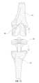
〔圖1〕為本發明的立體示意圖。[Figure 1] is a three-dimensional schematic diagram of the present invention.
〔圖2〕為本發明另一角度的立體示意圖。[Figure 2] is a three-dimensional schematic diagram of the present invention from another angle.
〔圖3~圖5〕為本發明的實施示意圖。[Figure 3 to Figure 5] are schematic diagrams of the implementation of the present invention.
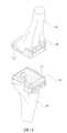
〔圖6~圖8〕為本發明3D列印技術製造的實施示意圖。[Figure 6~Figure 8] are schematic diagrams of the implementation of the 3D printing technology of the present invention.
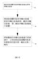
〔圖9〕為本發明3D列印技術製造的方塊流程示意圖。[Figure 9] is a schematic diagram of the block manufacturing process using the 3D printing technology of the present invention.
為能進一步瞭解本發明的特徵、技術手段以及所達到的具體目的、功能,下面結合附圖與具體實施方式對本發明作進一步詳細描述。In order to further understand the features, technical means, and specific objectives and functions of the present invention, the present invention is described in further detail below in conjunction with the attached drawings and specific implementation methods.
如圖1至圖5所示,圖中揭示出一種關節骨骼置換手術用醫療輔具,應用於股骨(10)和脛骨(20)上,該關節骨骼置換手術用醫療輔具(100)包括:一第一輔具(1),其具有一能貼合於欲切削之股骨(10)上的縱板部(11)、及一自該縱板部(11)底端橫向延伸並能貼合於欲切削之股骨(10)上的橫板部(12),該縱板部(11)、該橫板部(12)頂端具有符合該股骨(10)之形狀的第一貼合面(13),且該縱板部(11)一側設置有一第一切割道(14)及複數個鎖定孔(15),該第一切割道(14)能供一骨科鋸刀(30)切鋸欲切削之股骨(10)用,而該鎖定孔(15)能供骨釘穿過並將該第一輔具(1)固定於該股骨(10);以及一第二輔具(2),其與該第一輔具(1)上下對應並固定於欲切削之脛骨(20)上,該第二輔具(2)底端具有符合該脛骨(20)之形狀的第二貼合面(21),且該第二輔具(2)一側設置有一第二切割道(22)及複數個固定孔(23),該第二切割道(22)能供該骨科鋸刀(30)切鋸欲切削之脛骨(20)用,而該固定孔(23)能供骨釘穿過並將該第二輔具(2)固定於該脛骨(20)。As shown in FIGS. 1 to 5, a medical auxiliary tool for joint bone replacement surgery is disclosed, which is applied to a femur (10) and a tibia (20). The medical auxiliary tool (100) for joint bone replacement surgery comprises: a first auxiliary tool (1) having a longitudinal plate portion (11) that can be attached to the femur (10) to be cut, and a transverse plate portion (11) extending from the bottom end of the longitudinal plate portion (11) to the bottom end of the longitudinal plate portion (11). The invention relates to a transverse plate portion (12) extending in the longitudinal direction and being able to fit on the femur (10) to be cut, the longitudinal plate portion (11) and the top end of the transverse plate portion (12) have a first fitting surface (13) conforming to the shape of the femur (10), and a first cutting path (14) and a plurality of locking holes (15) are provided on one side of the longitudinal plate portion (11), and the first cutting path (14) can provide a The orthopedic saw (30) is used to saw the femur (10) to be cut, and the locking hole (15) can be used for the bone nail to pass through and fix the first auxiliary tool (1) to the femur (10); and a second auxiliary tool (2) which corresponds to the first auxiliary tool (1) above and below and is fixed on the tibia (20) to be cut, and the bottom end of the second auxiliary tool (2) has a shape that conforms to the tibia (20). The second auxiliary tool (2) has a second fitting surface (21) of a shape, and a second cutting path (22) and a plurality of fixing holes (23) are provided on one side of the second auxiliary tool (2). The second cutting path (22) can be used by the orthopedic saw (30) to cut the tibia (20) to be cut, and the fixing holes (23) can be used for bone nails to pass through and fix the second auxiliary tool (2) to the tibia (20).
其中,通過該第一輔具(1)、該第二輔具(2)的應用,可以使臨床醫師在進行切鋸關節骨骼手術時更加精確、快速和方便,讓手術操作過程更加容易且可控,以提供更加精確和安全的手術效果。Among them, through the application of the first auxiliary tool (1) and the second auxiliary tool (2), clinical doctors can perform joint bone cutting surgery more accurately, quickly and conveniently, making the surgical operation process easier and more controllable, thereby providing a more accurate and safe surgical effect.
其次,通過該第一貼合面(13)、該第二貼合面(21)的應用,能確保該第一輔具(1)、該第二輔具(2)與欲切削的關節骨骼緊密貼合,使本發明關節骨骼置換手術用醫療輔具與骨骼之間有良好的接觸,讓臨床醫師能夠精確切除受損的股骨(10)和脛骨(20)表面,以確保術後人工關節假體(80)能適當安裝和穩定支撐,從而恢復正常的關節功能,提供良好的手術效果。Secondly, through the application of the first fitting surface (13) and the second fitting surface (21), it is possible to ensure that the first auxiliary device (1) and the second auxiliary device (2) are closely fitted to the joint bone to be cut, so that the medical auxiliary device for joint bone replacement surgery of the present invention has good contact with the bone, allowing the clinician to accurately remove the damaged surface of the femur (10) and tibia (20), so as to ensure that the artificial joint prosthesis (80) can be properly installed and stably supported after the operation, thereby restoring normal joint function and providing good surgical results.
再者,通過該第一切割道(14)、該第二切割道(22)、該鎖定孔(15)和該固定孔(23)的設置,可準確地引導該骨科鋸刀(30)和骨釘,在手術期間提供穩定固定,以確保手術的精確性和安全性,能夠使臨床醫師更容易進行手術,同時提供可控制的操作環境,提高手術的效率和成功率。Furthermore, by providing the first cutting path (14), the second cutting path (22), the locking hole (15) and the fixing hole (23), the orthopedic saw (30) and the bone nail can be accurately guided to provide stable fixation during the operation to ensure the accuracy and safety of the operation, making it easier for the clinician to perform the operation, while providing a controllable operating environment to improve the efficiency and success rate of the operation.
上述中,所述橫板部(12)上還包含有一能供十字形韌帶貫穿通過的缺口(121);藉此,可以輕鬆地通過該缺口(121)將韌帶穿過該橫板部(12),不需要額外的工具或困難的操作。In the above, the cross plate portion (12) also includes a notch (121) through which the cross-shaped ligament can pass; thereby, the ligament can be easily passed through the cross plate portion (12) through the notch (121) without the need for additional tools or difficult operations.
上述中,所述縱板部(11)與該橫板部(12)是以一體成型的方式製成;據此,可以增加本發明關節骨骼置換手術用醫療輔具(100)的強度和穩定性,同時,可以減少組件之間的連接部位,減少潛在的失效點,從而提高整體的耐用性和可靠性,不僅使製造過程更容易,還能降低生產成本。In the above, the longitudinal plate portion (11) and the transverse plate portion (12) are formed in an integral manner; accordingly, the strength and stability of the medical auxiliary device (100) for joint bone replacement surgery of the present invention can be increased, and at the same time, the connection parts between components can be reduced, and the potential failure points can be reduced, thereby improving the overall durability and reliability, not only making the manufacturing process easier, but also reducing the production cost.
上述圖3還揭示出,所述第一切割道(14)是由一設置於該第一切割道(14)內並位於該第一切割道(14)上方的第一導引邊(141)、一設置於該第一切割道(14)內並位於該第一導引邊(141)下方的第二導引邊(142)、兩設置於該第一切割道(14)內並與該第一導引邊(141)和該第二導引邊(142)垂直連接、用於限制該骨科鋸刀(30)操作方向及/或操作範圍的第一槽壁(143)、及一位於該第一導引邊(141)、該第二導引邊(142)與該第一槽壁(143)之間並貫穿該縱板部(11)的第一鋸刀口(144)所組成;而所述第二切割道(22)是由一設置於該第二切割道(22)內並位於該第二切割道(22)上方的第三導引邊(221)、一設置於該第二切割道(22)內並位於該第三導引邊(221)下方的第四導引邊(222)、兩設置於該第二切割道(22)內並與該第三導引邊(221)和該第四導引邊(222)垂直連接、用於限制該骨科鋸刀(30)操作方向及/或操作範圍的第二槽壁(223)、及一位於該第三導引邊(221)、該第四導引邊(222)與該第二槽壁(223)之間並貫穿該第二輔具(2)的第二鋸刀口(224)所組成。FIG. 3 also discloses that the first cutting path (14) is composed of a first guide edge (141) disposed in the first cutting path (14) and located above the first cutting path (14), a second guide edge (142) disposed in the first cutting path (14) and located below the first guide edge (141), two first groove walls (143) disposed in the first cutting path (14) and vertically connected to the first guide edge (141) and the second guide edge (142) for limiting the operating direction and/or operating range of the orthopedic saw (30), and a first saw blade (144) disposed between the first guide edge (141), the second guide edge (142) and the first groove wall (143) and penetrating the longitudinal plate portion (11). The second cutting path (22) is composed of a third guide edge (221) disposed in the second cutting path (22) and located above the second cutting path (22), a fourth guide edge (222) disposed in the second cutting path (22) and located below the third guide edge (221), two second groove walls (223) disposed in the second cutting path (22) and vertically connected to the third guide edge (221) and the fourth guide edge (222) for limiting the operating direction and/or operating range of the orthopedic saw (30), and a second saw blade (224) disposed between the third guide edge (221), the fourth guide edge (222) and the second groove wall (223) and penetrating the second auxiliary tool (2).
其中,通過該第一導引邊(141)、該第二導引邊(142)、第三導引邊(221)、第四導引邊(222)與該第一槽壁(143)、該第二槽壁(223)的結合應用,一方面能對該骨科鋸刀(30)的操作方向進行控制,通過該第一槽壁(143)、該第二槽壁(223)限制該骨科鋸刀(30)兩側,包括操作方向及操作範圍等,以保證操作的精度,另一方面能對該骨科鋸刀(30)的操作程度進行控制,當該骨科鋸刀(30)的手柄與該第一導引邊(141)、該第二導引邊(142)、第三導引邊(221)、第四導引邊(222)的表面接觸時限制其操作的深度,以防止操作時傷及韌帶或神經線等。Among them, through the combined application of the first guide edge (141), the second guide edge (142), the third guide edge (221), the fourth guide edge (222) and the first groove wall (143), the second groove wall (223), on the one hand, the operation direction of the orthopedic saw (30) can be controlled, and the first groove wall (143) and the second groove wall (223) limit the two sides of the orthopedic saw (30), including the operation direction and the operation range, so as to ensure the accuracy of the operation. On the other hand, the operation degree of the orthopedic saw (30) can be controlled. When the handle of the orthopedic saw (30) contacts the surface of the first guide edge (141), the second guide edge (142), the third guide edge (221), and the fourth guide edge (222), the operation depth is limited to prevent the ligament or nerve from being injured during the operation.
如圖6至圖9所示,所述關節骨骼置換手術用醫療輔具(100),是通過3D列印技術製造而成,其包括以下步驟:步驟一(S1):獲取病患個體的股骨3D數位影像(40)及脛骨3D數位影像(50);步驟二(S2):將病患個體的股骨3D數位影像(40)、脛骨3D數位影像(50)與第一輔具3D數位影像(60)、第二輔具3D數位影像(70)進行重疊;步驟三(S3):將重疊後的3D數位影像進行相減操作,以得到與病患個體的股骨(10)和脛骨(20)相匹配的第一輔具(1)及第二輔具(2);據此,可以根據病患個體的骨骼結構進行量身定制,以確保關節骨骼置換手術用醫療輔具與患者的骨骼完美匹配,提供更好的手術效果。As shown in FIGS. 6 to 9 , the medical assistive device (100) for joint bone replacement surgery is manufactured by 3D printing technology, and includes the following steps: Step 1 (S1): Obtaining a 3D digital image of the femur (40) and a 3D digital image of the tibia (50) of the patient; Step 2 (S2): Connecting the 3D digital image of the femur (40) and the 3D digital image of the tibia (50) of the patient with the 3D digital image of the first assistive device (60); , and the second auxiliary tool 3D digital image (70) are overlapped; step three (S3): the overlapped 3D digital images are subtracted to obtain the first auxiliary tool (1) and the second auxiliary tool (2) that match the femur (10) and tibia (20) of the individual patient; accordingly, the auxiliary tool can be customized according to the individual patient's bone structure to ensure that the medical auxiliary tool for joint bone replacement surgery perfectly matches the patient's bones and provides better surgical results.
因此,由上述之實施說明可知,本發明提供了一種關節骨骼置換手術用醫療輔具,能讓臨床醫師在進行切鋸關節骨骼手術時更加精確、快速和方便,讓手術操作過程更加容易且可控,以提供更加精確和安全的手術效果,故具有推廣意義價值與重要性,值得廣泛加以使用,以符合現今關節骨骼置換手術之發展趨勢。Therefore, from the above implementation description, it can be seen that the present invention provides a medical auxiliary device for joint bone replacement surgery, which can make clinical doctors more accurate, fast and convenient when performing joint bone cutting surgery, making the surgical operation process easier and more controllable, so as to provide more accurate and safe surgical results. Therefore, it has promotional significance, value and importance, and is worthy of wide use to meet the current development trend of joint bone replacement surgery.
以上詳細說明了本發明的方法、作用及功效;惟以上所述為本發明較佳實施例,並非用於限定範圍,因此舉凡一切與本發明意旨相符的修飾性變化,在均等效果的範疇內都應涵屬於本發明專利範圍。The above details the method, function and effect of the present invention; however, the above is a preferred embodiment of the present invention and is not intended to limit the scope. Therefore, all modifications consistent with the intent of the present invention should be included in the patent scope of the present invention within the scope of equal effect.
1:第一輔具1: The first auxiliary tool
15:鎖定孔15: Locking hole
11:縱板部11: Vertical board section
2:第二輔具2: Second auxiliary tool
12:橫板部12: Horizontal board
22:第二切割道22: Second cutting path
121:缺口121: Gap
221:第三導引邊221: Third guide edge
13:第一貼合面13: First bonding surface
222:第四導引邊222: Fourth guide edge
14:第一切割道14: First cutting path
223:第二槽壁223: Second groove wall
141:第一導引邊141: First guide edge
224:第二鋸刀口224: Second saw blade
142:第二導引邊142: Second guide edge
23:固定孔23:Fixing hole
143:第一槽壁143: First groove wall
100:關節骨骼置換手術用醫療輔具100: Medical assistive devices for joint bone replacement surgery
144:第一鋸刀口144: The first saw blade
Claims (6)
Translated fromChinesePriority Applications (2)
| Application Number | Priority Date | Filing Date | Title |
|---|---|---|---|
| TW112140017ATWI851452B (en) | 2023-10-19 | 2023-10-19 | Medical assistive devices for joint bone replacement surgery |
| US18/914,289US20250127521A1 (en) | 2023-10-19 | 2024-10-14 | Medical Auxiliary Device for Joint Bone Replacement Surgery |
Applications Claiming Priority (1)
| Application Number | Priority Date | Filing Date | Title |
|---|---|---|---|
| TW112140017ATWI851452B (en) | 2023-10-19 | 2023-10-19 | Medical assistive devices for joint bone replacement surgery |
Publications (2)
| Publication Number | Publication Date |
|---|---|
| TWI851452Btrue TWI851452B (en) | 2024-08-01 |
| TW202517223A TW202517223A (en) | 2025-05-01 |
Family
ID=93283836
Family Applications (1)
| Application Number | Title | Priority Date | Filing Date |
|---|---|---|---|
| TW112140017ATWI851452B (en) | 2023-10-19 | 2023-10-19 | Medical assistive devices for joint bone replacement surgery |
Country Status (2)
| Country | Link |
|---|---|
| US (1) | US20250127521A1 (en) |
| TW (1) | TWI851452B (en) |
Citations (4)
| Publication number | Priority date | Publication date | Assignee | Title |
|---|---|---|---|---|
| TWM294922U (en)* | 2005-12-19 | 2006-08-01 | Ying-He Chen | Improved structure of ruler for artificial knee joint replacement |
| US20160089168A1 (en)* | 2001-03-05 | 2016-03-31 | Puget BioBentures LLC | Method and apparatus for total knee arthroplasty |
| US9943317B2 (en)* | 2009-05-29 | 2018-04-17 | Smith & Nephew, Inc. | Methods and apparatus for performing knee arthroplasty |
| CN210932054U (en)* | 2019-07-05 | 2020-07-07 | 扬州大学附属医院 | Auxiliary bone cutting guide plate for knee joint unicondylar replacement |
- 2023
- 2023-10-19TWTW112140017Apatent/TWI851452B/enactive
- 2024
- 2024-10-14USUS18/914,289patent/US20250127521A1/enactivePending
Patent Citations (5)
| Publication number | Priority date | Publication date | Assignee | Title |
|---|---|---|---|---|
| US20160089168A1 (en)* | 2001-03-05 | 2016-03-31 | Puget BioBentures LLC | Method and apparatus for total knee arthroplasty |
| US9421022B2 (en)* | 2001-03-05 | 2016-08-23 | Puget Bioventures Llc | Method and apparatus for total knee arthroplasty |
| TWM294922U (en)* | 2005-12-19 | 2006-08-01 | Ying-He Chen | Improved structure of ruler for artificial knee joint replacement |
| US9943317B2 (en)* | 2009-05-29 | 2018-04-17 | Smith & Nephew, Inc. | Methods and apparatus for performing knee arthroplasty |
| CN210932054U (en)* | 2019-07-05 | 2020-07-07 | 扬州大学附属医院 | Auxiliary bone cutting guide plate for knee joint unicondylar replacement |
Also Published As
| Publication number | Publication date |
|---|---|
| US20250127521A1 (en) | 2025-04-24 |
| TW202517223A (en) | 2025-05-01 |
Similar Documents
| Publication | Publication Date | Title |
|---|---|---|
| US11026699B2 (en) | Tibial tubercule osteotomy | |
| US20210361437A1 (en) | Patient Adapted Joint Arthroplasty Systems, Devices, Surgical Tools and Methods of Use | |
| US20210219989A1 (en) | Tibial Guides, Tools and Techniques for Resecting the Tibial Plateau | |
| US10426492B2 (en) | Patient specific alignment guide with cutting surface and laser indicator | |
| US11839388B2 (en) | Surgical alignment guide assembly for total ankle replacement and method of using the same | |
| US9993256B2 (en) | Customized unicompartmental tibial cutting guide | |
| CN102743214B (en) | A tibial osteotomy positioning device | |
| JPH02501806A (en) | Bone cutting guide and how to use it | |
| CN204468186U (en) | A kind of patella osteotomy navigation template for knee prosthesis | |
| KR102140052B1 (en) | Osteotomy device with an in-vitro alignment component | |
| KR20200068004A (en) | Surgical device for osteotomy | |
| CN110584741B (en) | Osteotomy guide | |
| CN204909559U (en) | Individuation knee joint thighbone distal end cuts bone conduction board | |
| TWM536526U (en) | A surgery device for osteotomy | |
| TWI851452B (en) | Medical assistive devices for joint bone replacement surgery | |
| US10729451B2 (en) | Universal osteotomy device | |
| CN113243967A (en) | Navigation device for knee-walking total knee joint replacement | |
| CN108784782A (en) | 3D printing condyle of femur 5 closes 1 integration osteotomy device and its forming method | |
| CN108784821B (en) | Personalized customization 3D printing osteotomy guide plate and use method thereof | |
| CN217592978U (en) | 3D prints assembled knee joint and cuts bone baffle | |
| US20230389937A1 (en) | Surgical guide with cutting depth information | |
| TWM523427U (en) | A surgery device for high tibial osteotomy | |
| CN117017418A (en) | Ankle joint personalized osteotomy and bone grafting guiding device and application thereof | |
| CN110575221A (en) | Bone cutting guide plate for accurate treatment of tibial tubercle internal shift operation and application thereof | |
| CN112932608B (en) | Unicompartmental replacement integrated femoral osteotomy guide plate |