TWI848502B - Semiconductor device and method of forming the same - Google Patents
Semiconductor device and method of forming the sameDownload PDFInfo
- Publication number
- TWI848502B TWI848502BTW112100326ATW112100326ATWI848502BTW I848502 BTWI848502 BTW I848502BTW 112100326 ATW112100326 ATW 112100326ATW 112100326 ATW112100326 ATW 112100326ATW I848502 BTWI848502 BTW I848502B
- Authority
- TW
- Taiwan
- Prior art keywords
- nanostructure
- layer
- source
- semiconductor device
- width
- Prior art date
Links
- 239000004065semiconductorSubstances0.000titleclaimsabstractdescription388
- 238000000034methodMethods0.000titleclaimsabstractdescription186
- 239000002086nanomaterialSubstances0.000claimsabstractdescription370
- 229910044991metal oxideInorganic materials0.000claimsabstractdescription70
- 150000004706metal oxidesChemical class0.000claimsabstractdescription70
- 230000003068static effectEffects0.000claimsabstractdescription26
- 239000000758substrateSubstances0.000claimsdescription132
- 230000015572biosynthetic processEffects0.000abstractdescription9
- 239000010410layerSubstances0.000description402
- 230000008569processEffects0.000description114
- 238000000151depositionMethods0.000description71
- 238000005530etchingMethods0.000description67
- 239000000463materialSubstances0.000description59
- 230000008021depositionEffects0.000description55
- 125000006850spacer groupChemical group0.000description43
- 238000002955isolationMethods0.000description41
- XUIMIQQOPSSXEZ-UHFFFAOYSA-NSiliconChemical compound[Si]XUIMIQQOPSSXEZ-UHFFFAOYSA-N0.000description35
- 239000010703siliconSubstances0.000description35
- 229910052710siliconInorganic materials0.000description34
- 238000004519manufacturing processMethods0.000description27
- 238000010586diagramMethods0.000description20
- 238000007747platingMethods0.000description20
- 229910000577Silicon-germaniumInorganic materials0.000description19
- 230000015654memoryEffects0.000description19
- LEVVHYCKPQWKOP-UHFFFAOYSA-N[Si].[Ge]Chemical compound[Si].[Ge]LEVVHYCKPQWKOP-UHFFFAOYSA-N0.000description18
- 239000003989dielectric materialSubstances0.000description17
- 229920002120photoresistant polymerPolymers0.000description17
- 238000005229chemical vapour depositionMethods0.000description15
- 239000011229interlayerSubstances0.000description15
- 150000004767nitridesChemical class0.000description15
- 238000012546transferMethods0.000description13
- VYPSYNLAJGMNEJ-UHFFFAOYSA-NSilicium dioxideChemical compoundO=[Si]=OVYPSYNLAJGMNEJ-UHFFFAOYSA-N0.000description12
- 239000000203mixtureSubstances0.000description11
- 238000005498polishingMethods0.000description11
- 238000012545processingMethods0.000description11
- KRHYYFGTRYWZRS-UHFFFAOYSA-NFluoraneChemical compoundFKRHYYFGTRYWZRS-UHFFFAOYSA-N0.000description10
- 229910052581Si3N4Inorganic materials0.000description10
- 229910052732germaniumInorganic materials0.000description10
- GNPVGFCGXDBREM-UHFFFAOYSA-Ngermanium atomChemical compound[Ge]GNPVGFCGXDBREM-UHFFFAOYSA-N0.000description10
- HQVNEWCFYHHQES-UHFFFAOYSA-Nsilicon nitrideChemical compoundN12[Si]34N5[Si]62N3[Si]51N64HQVNEWCFYHHQES-UHFFFAOYSA-N0.000description10
- 229910052814silicon oxideInorganic materials0.000description10
- 239000000126substanceSubstances0.000description10
- 238000000231atomic layer depositionMethods0.000description9
- 239000002019doping agentSubstances0.000description9
- 230000000694effectsEffects0.000description9
- 230000007547defectEffects0.000description8
- 238000005240physical vapour depositionMethods0.000description8
- QGZKDVFQNNGYKY-UHFFFAOYSA-NAmmoniaChemical compoundNQGZKDVFQNNGYKY-UHFFFAOYSA-N0.000description7
- 238000005253claddingMethods0.000description7
- 238000005516engineering processMethods0.000description7
- 230000005669field effectEffects0.000description7
- 239000002135nanosheetSubstances0.000description7
- 238000000206photolithographyMethods0.000description7
- 239000011248coating agentSubstances0.000description6
- 238000000576coating methodMethods0.000description6
- 238000004891communicationMethods0.000description6
- 238000001312dry etchingMethods0.000description6
- 238000000059patterningMethods0.000description6
- 238000001020plasma etchingMethods0.000description6
- JBRZTFJDHDCESZ-UHFFFAOYSA-NAsGaChemical compound[As]#[Ga]JBRZTFJDHDCESZ-UHFFFAOYSA-N0.000description5
- ZOXJGFHDIHLPTG-UHFFFAOYSA-NBoronChemical compound[B]ZOXJGFHDIHLPTG-UHFFFAOYSA-N0.000description5
- 229910001218Gallium arsenideInorganic materials0.000description5
- 239000000956alloySubstances0.000description5
- 230000004888barrier functionEffects0.000description5
- 229910052796boronInorganic materials0.000description5
- 238000011161developmentMethods0.000description5
- 229910052751metalInorganic materials0.000description5
- 239000002184metalSubstances0.000description5
- 239000011259mixed solutionSubstances0.000description5
- 238000007789sealingMethods0.000description5
- ABTOQLMXBSRXSM-UHFFFAOYSA-Nsilicon tetrafluorideChemical compoundF[Si](F)(F)FABTOQLMXBSRXSM-UHFFFAOYSA-N0.000description5
- IJGRMHOSHXDMSA-UHFFFAOYSA-NAtomic nitrogenChemical compoundN#NIJGRMHOSHXDMSA-UHFFFAOYSA-N0.000description4
- 229910045601alloyInorganic materials0.000description4
- -1ammonium fluorosilicateChemical compound0.000description4
- 239000006227byproductSubstances0.000description4
- 238000004140cleaningMethods0.000description4
- 230000008878couplingEffects0.000description4
- 238000010168coupling processMethods0.000description4
- 238000005859coupling reactionMethods0.000description4
- 239000002070nanowireSubstances0.000description4
- 230000003647oxidationEffects0.000description4
- 238000007254oxidation reactionMethods0.000description4
- 230000005855radiationEffects0.000description4
- 230000009467reductionEffects0.000description4
- 239000012686silicon precursorSubstances0.000description4
- XLYOFNOQVPJJNP-UHFFFAOYSA-NwaterSubstancesOXLYOFNOQVPJJNP-UHFFFAOYSA-N0.000description4
- QTBSBXVTEAMEQO-UHFFFAOYSA-NAcetic acidChemical compoundCC(O)=OQTBSBXVTEAMEQO-UHFFFAOYSA-N0.000description3
- YCKRFDGAMUMZLT-UHFFFAOYSA-NFluorine atomChemical compound[F]YCKRFDGAMUMZLT-UHFFFAOYSA-N0.000description3
- 229910000530Gallium indium arsenideInorganic materials0.000description3
- 229910000673Indium arsenideInorganic materials0.000description3
- GPXJNWSHGFTCBW-UHFFFAOYSA-NIndium phosphideChemical compound[In]#PGPXJNWSHGFTCBW-UHFFFAOYSA-N0.000description3
- OAICVXFJPJFONN-UHFFFAOYSA-NPhosphorusChemical compound[P]OAICVXFJPJFONN-UHFFFAOYSA-N0.000description3
- 101100012902Saccharomyces cerevisiae (strain ATCC 204508 / S288c) FIG2 geneProteins0.000description3
- 229910021529ammoniaInorganic materials0.000description3
- 239000012159carrier gasSubstances0.000description3
- 150000001875compoundsChemical class0.000description3
- 238000009792diffusion processMethods0.000description3
- PZPGRFITIJYNEJ-UHFFFAOYSA-NdisilaneChemical compound[SiH3][SiH3]PZPGRFITIJYNEJ-UHFFFAOYSA-N0.000description3
- 229910052731fluorineInorganic materials0.000description3
- 239000011737fluorineSubstances0.000description3
- 229940104869fluorosilicateDrugs0.000description3
- 230000006870functionEffects0.000description3
- 239000011521glassSubstances0.000description3
- 239000001257hydrogenSubstances0.000description3
- 229910052739hydrogenInorganic materials0.000description3
- 238000002513implantationMethods0.000description3
- 239000011810insulating materialSubstances0.000description3
- 229910052698phosphorusInorganic materials0.000description3
- 239000011574phosphorusSubstances0.000description3
- 239000002210silicon-based materialSubstances0.000description3
- 239000011800void materialSubstances0.000description3
- 238000003631wet chemical etchingMethods0.000description3
- 238000001039wet etchingMethods0.000description3
- XKRFYHLGVUSROY-UHFFFAOYSA-NArgonChemical compound[Ar]XKRFYHLGVUSROY-UHFFFAOYSA-N0.000description2
- UFHFLCQGNIYNRP-UHFFFAOYSA-NHydrogenChemical compound[H][H]UFHFLCQGNIYNRP-UHFFFAOYSA-N0.000description2
- MHAJPDPJQMAIIY-UHFFFAOYSA-NHydrogen peroxideChemical compoundOOMHAJPDPJQMAIIY-UHFFFAOYSA-N0.000description2
- PXHVJJICTQNCMI-UHFFFAOYSA-NNickelChemical compound[Ni]PXHVJJICTQNCMI-UHFFFAOYSA-N0.000description2
- 229910004014SiF4Inorganic materials0.000description2
- 238000003917TEM imageMethods0.000description2
- FTWRSWRBSVXQPI-UHFFFAOYSA-Nalumanylidynearsane;gallanylidynearsaneChemical compound[As]#[Al].[As]#[Ga]FTWRSWRBSVXQPI-UHFFFAOYSA-N0.000description2
- AJGDITRVXRPLBY-UHFFFAOYSA-Naluminum indiumChemical compound[Al].[In]AJGDITRVXRPLBY-UHFFFAOYSA-N0.000description2
- 229910052785arsenicInorganic materials0.000description2
- RQNWIZPPADIBDY-UHFFFAOYSA-Narsenic atomChemical compound[As]RQNWIZPPADIBDY-UHFFFAOYSA-N0.000description2
- 229910000416bismuth oxideInorganic materials0.000description2
- 230000008859changeEffects0.000description2
- 238000005137deposition processMethods0.000description2
- 238000013461designMethods0.000description2
- TYIXMATWDRGMPF-UHFFFAOYSA-Ndibismuth;oxygen(2-)Chemical compound[O-2].[O-2].[O-2].[Bi+3].[Bi+3]TYIXMATWDRGMPF-UHFFFAOYSA-N0.000description2
- 238000001035dryingMethods0.000description2
- 238000000609electron-beam lithographyMethods0.000description2
- 230000009969flowable effectEffects0.000description2
- 150000002739metalsChemical class0.000description2
- VNWKTOKETHGBQD-UHFFFAOYSA-NmethaneChemical compoundCVNWKTOKETHGBQD-UHFFFAOYSA-N0.000description2
- 230000005012migrationEffects0.000description2
- 238000013508migrationMethods0.000description2
- 229910052757nitrogenInorganic materials0.000description2
- 230000000149penetrating effectEffects0.000description2
- 229910021420polycrystalline siliconInorganic materials0.000description2
- 229920005591polysiliconPolymers0.000description2
- 239000002243precursorSubstances0.000description2
- 229910010271silicon carbideInorganic materials0.000description2
- HBMJWWWQQXIZIP-UHFFFAOYSA-Nsilicon carbideChemical compound[Si+]#[C-]HBMJWWWQQXIZIP-UHFFFAOYSA-N0.000description2
- 238000001179sorption measurementMethods0.000description2
- 238000004528spin coatingMethods0.000description2
- WGTYBPLFGIVFAS-UHFFFAOYSA-Mtetramethylammonium hydroxideChemical compound[OH-].C[N+](C)(C)CWGTYBPLFGIVFAS-UHFFFAOYSA-M0.000description2
- 238000009966trimmingMethods0.000description2
- 230000005641tunnelingEffects0.000description2
- ZRNSSRODJSSVEJ-UHFFFAOYSA-N2-methylpentacosaneChemical compoundCCCCCCCCCCCCCCCCCCCCCCCC(C)CZRNSSRODJSSVEJ-UHFFFAOYSA-N0.000description1
- OKTJSMMVPCPJKN-UHFFFAOYSA-NCarbonChemical compound[C]OKTJSMMVPCPJKN-UHFFFAOYSA-N0.000description1
- RYGMFSIKBFXOCR-UHFFFAOYSA-NCopperChemical compound[Cu]RYGMFSIKBFXOCR-UHFFFAOYSA-N0.000description1
- 229910005540GaPInorganic materials0.000description1
- GYHNNYVSQQEPJS-UHFFFAOYSA-NGalliumChemical compound[Ga]GYHNNYVSQQEPJS-UHFFFAOYSA-N0.000description1
- VEXZGXHMUGYJMC-UHFFFAOYSA-NHydrochloric acidChemical compoundClVEXZGXHMUGYJMC-UHFFFAOYSA-N0.000description1
- 229910018503SF6Inorganic materials0.000description1
- BLRPTPMANUNPDV-UHFFFAOYSA-NSilaneChemical compound[SiH4]BLRPTPMANUNPDV-UHFFFAOYSA-N0.000description1
- ATJFFYVFTNAWJD-UHFFFAOYSA-NTinChemical compound[Sn]ATJFFYVFTNAWJD-UHFFFAOYSA-N0.000description1
- 238000005411Van der Waals forceMethods0.000description1
- QCEUXSAXTBNJGO-UHFFFAOYSA-N[Ag].[Sn]Chemical compound[Ag].[Sn]QCEUXSAXTBNJGO-UHFFFAOYSA-N0.000description1
- 239000003082abrasive agentSubstances0.000description1
- 229910052782aluminiumInorganic materials0.000description1
- XAGFODPZIPBFFR-UHFFFAOYSA-NaluminiumChemical compound[Al]XAGFODPZIPBFFR-UHFFFAOYSA-N0.000description1
- 229910052786argonInorganic materials0.000description1
- 238000000277atomic layer chemical vapour depositionMethods0.000description1
- 230000000903blocking effectEffects0.000description1
- 229910052799carbonInorganic materials0.000description1
- 239000000969carrierSubstances0.000description1
- 230000015556catabolic processEffects0.000description1
- 238000003486chemical etchingMethods0.000description1
- 238000006243chemical reactionMethods0.000description1
- 229910052681coesiteInorganic materials0.000description1
- 239000004020conductorSubstances0.000description1
- 239000000356contaminantSubstances0.000description1
- 229910052802copperInorganic materials0.000description1
- 239000010949copperSubstances0.000description1
- 229910052906cristobaliteInorganic materials0.000description1
- 239000013078crystalSubstances0.000description1
- 238000006731degradation reactionMethods0.000description1
- 238000005566electron beam evaporationMethods0.000description1
- 238000010894electron beam technologyMethods0.000description1
- 238000009713electroplatingMethods0.000description1
- 238000001125extrusionMethods0.000description1
- 229910052733galliumInorganic materials0.000description1
- HZXMRANICFIONG-UHFFFAOYSA-Ngallium phosphideChemical compound[Ga]#PHZXMRANICFIONG-UHFFFAOYSA-N0.000description1
- 239000007789gasSubstances0.000description1
- YBMRDBCBODYGJE-UHFFFAOYSA-Ngermanium oxideInorganic materialsO=[Ge]=OYBMRDBCBODYGJE-UHFFFAOYSA-N0.000description1
- 238000000227grindingMethods0.000description1
- XLYOFNOQVPJJNP-ZSJDYOACSA-Nheavy waterSubstances[2H]O[2H]XLYOFNOQVPJJNP-ZSJDYOACSA-N0.000description1
- 239000001307heliumSubstances0.000description1
- 229910052734heliumInorganic materials0.000description1
- SWQJXJOGLNCZEY-UHFFFAOYSA-Nhelium atomChemical compound[He]SWQJXJOGLNCZEY-UHFFFAOYSA-N0.000description1
- 150000002431hydrogenChemical class0.000description1
- IXCSERBJSXMMFS-UHFFFAOYSA-Nhydrogen chlorideSubstancesCl.ClIXCSERBJSXMMFS-UHFFFAOYSA-N0.000description1
- 229910000041hydrogen chlorideInorganic materials0.000description1
- WPYVAWXEWQSOGY-UHFFFAOYSA-Nindium antimonideChemical compound[Sb]#[In]WPYVAWXEWQSOGY-UHFFFAOYSA-N0.000description1
- RPQDHPTXJYYUPQ-UHFFFAOYSA-Nindium arsenideChemical compound[In]#[As]RPQDHPTXJYYUPQ-UHFFFAOYSA-N0.000description1
- 230000006698inductionEffects0.000description1
- 238000009413insulationMethods0.000description1
- 239000012212insulatorSubstances0.000description1
- 238000005468ion implantationMethods0.000description1
- 230000001788irregularEffects0.000description1
- LQBJWKCYZGMFEV-UHFFFAOYSA-Nlead tinChemical compound[Sn].[Pb]LQBJWKCYZGMFEV-UHFFFAOYSA-N0.000description1
- 239000007788liquidSubstances0.000description1
- 238000004518low pressure chemical vapour depositionMethods0.000description1
- 230000000873masking effectEffects0.000description1
- 230000007246mechanismEffects0.000description1
- 239000007769metal materialSubstances0.000description1
- 238000001451molecular beam epitaxyMethods0.000description1
- NBVXSUQYWXRMNV-UHFFFAOYSA-NmonofluoromethaneNatural productsFCNBVXSUQYWXRMNV-UHFFFAOYSA-N0.000description1
- 239000002105nanoparticleSubstances0.000description1
- 229910052759nickelInorganic materials0.000description1
- QJGQUHMNIGDVPM-UHFFFAOYSA-Nnitrogen groupChemical group[N]QJGQUHMNIGDVPM-UHFFFAOYSA-N0.000description1
- 230000003287optical effectEffects0.000description1
- JMANVNJQNLATNU-UHFFFAOYSA-NoxalonitrileChemical compoundN#CC#NJMANVNJQNLATNU-UHFFFAOYSA-N0.000description1
- PVADDRMAFCOOPC-UHFFFAOYSA-NoxogermaniumChemical compound[Ge]=OPVADDRMAFCOOPC-UHFFFAOYSA-N0.000description1
- 230000003071parasitic effectEffects0.000description1
- 238000000623plasma-assisted chemical vapour depositionMethods0.000description1
- 239000000376reactantSubstances0.000description1
- 239000013557residual solventSubstances0.000description1
- 230000001953sensory effectEffects0.000description1
- 229910000077silaneInorganic materials0.000description1
- 229910021332silicideInorganic materials0.000description1
- 239000000377silicon dioxideSubstances0.000description1
- 235000012239silicon dioxideNutrition0.000description1
- XJKVPKYVPCWHFO-UHFFFAOYSA-Nsilicon;hydrateChemical compoundO.[Si]XJKVPKYVPCWHFO-UHFFFAOYSA-N0.000description1
- 238000004544sputter depositionMethods0.000description1
- 229910052682stishoviteInorganic materials0.000description1
- 238000003860storageMethods0.000description1
- 238000006467substitution reactionMethods0.000description1
- SFZCNBIFKDRMGX-UHFFFAOYSA-Nsulfur hexafluorideChemical compoundFS(F)(F)(F)(F)FSFZCNBIFKDRMGX-UHFFFAOYSA-N0.000description1
- 229960000909sulfur hexafluorideDrugs0.000description1
- 238000004381surface treatmentMethods0.000description1
- 239000000725suspensionSubstances0.000description1
- 238000012876topographyMethods0.000description1
- 229910052905tridymiteInorganic materials0.000description1
Images


Classifications
- H—ELECTRICITY
- H10—SEMICONDUCTOR DEVICES; ELECTRIC SOLID-STATE DEVICES NOT OTHERWISE PROVIDED FOR
- H10D—INORGANIC ELECTRIC SEMICONDUCTOR DEVICES
- H10D62/00—Semiconductor bodies, or regions thereof, of devices having potential barriers
- H10D62/10—Shapes, relative sizes or dispositions of the regions of the semiconductor bodies; Shapes of the semiconductor bodies
- H10D62/117—Shapes of semiconductor bodies
- H10D62/118—Nanostructure semiconductor bodies
- H—ELECTRICITY
- H10—SEMICONDUCTOR DEVICES; ELECTRIC SOLID-STATE DEVICES NOT OTHERWISE PROVIDED FOR
- H10B—ELECTRONIC MEMORY DEVICES
- H10B10/00—Static random access memory [SRAM] devices
- H10B10/12—Static random access memory [SRAM] devices comprising a MOSFET load element
- H10B10/125—Static random access memory [SRAM] devices comprising a MOSFET load element the MOSFET being a thin film transistor [TFT]
- H—ELECTRICITY
- H10—SEMICONDUCTOR DEVICES; ELECTRIC SOLID-STATE DEVICES NOT OTHERWISE PROVIDED FOR
- H10D—INORGANIC ELECTRIC SEMICONDUCTOR DEVICES
- H10D30/00—Field-effect transistors [FET]
- H10D30/01—Manufacture or treatment
- H10D30/014—Manufacture or treatment of FETs having zero-dimensional [0D] or one-dimensional [1D] channels, e.g. quantum wire FETs, single-electron transistors [SET] or Coulomb blockade transistors
- H—ELECTRICITY
- H10—SEMICONDUCTOR DEVICES; ELECTRIC SOLID-STATE DEVICES NOT OTHERWISE PROVIDED FOR
- H10D—INORGANIC ELECTRIC SEMICONDUCTOR DEVICES
- H10D30/00—Field-effect transistors [FET]
- H10D30/01—Manufacture or treatment
- H10D30/021—Manufacture or treatment of FETs having insulated gates [IGFET]
- H10D30/031—Manufacture or treatment of FETs having insulated gates [IGFET] of thin-film transistors [TFT]
- H—ELECTRICITY
- H10—SEMICONDUCTOR DEVICES; ELECTRIC SOLID-STATE DEVICES NOT OTHERWISE PROVIDED FOR
- H10D—INORGANIC ELECTRIC SEMICONDUCTOR DEVICES
- H10D30/00—Field-effect transistors [FET]
- H10D30/40—FETs having zero-dimensional [0D], one-dimensional [1D] or two-dimensional [2D] charge carrier gas channels
- H10D30/43—FETs having zero-dimensional [0D], one-dimensional [1D] or two-dimensional [2D] charge carrier gas channels having 1D charge carrier gas channels, e.g. quantum wire FETs or transistors having 1D quantum-confined channels
- H—ELECTRICITY
- H10—SEMICONDUCTOR DEVICES; ELECTRIC SOLID-STATE DEVICES NOT OTHERWISE PROVIDED FOR
- H10D—INORGANIC ELECTRIC SEMICONDUCTOR DEVICES
- H10D30/00—Field-effect transistors [FET]
- H10D30/60—Insulated-gate field-effect transistors [IGFET]
- H10D30/67—Thin-film transistors [TFT]
- H10D30/6704—Thin-film transistors [TFT] having supplementary regions or layers in the thin films or in the insulated bulk substrates for controlling properties of the device
- H10D30/6713—Thin-film transistors [TFT] having supplementary regions or layers in the thin films or in the insulated bulk substrates for controlling properties of the device characterised by the properties of the source or drain regions, e.g. compositions or sectional shapes
- H—ELECTRICITY
- H10—SEMICONDUCTOR DEVICES; ELECTRIC SOLID-STATE DEVICES NOT OTHERWISE PROVIDED FOR
- H10D—INORGANIC ELECTRIC SEMICONDUCTOR DEVICES
- H10D30/00—Field-effect transistors [FET]
- H10D30/60—Insulated-gate field-effect transistors [IGFET]
- H10D30/67—Thin-film transistors [TFT]
- H10D30/6729—Thin-film transistors [TFT] characterised by the electrodes
- H10D30/673—Thin-film transistors [TFT] characterised by the electrodes characterised by the shapes, relative sizes or dispositions of the gate electrodes
- H10D30/6735—Thin-film transistors [TFT] characterised by the electrodes characterised by the shapes, relative sizes or dispositions of the gate electrodes having gates fully surrounding the channels, e.g. gate-all-around
- H—ELECTRICITY
- H10—SEMICONDUCTOR DEVICES; ELECTRIC SOLID-STATE DEVICES NOT OTHERWISE PROVIDED FOR
- H10D—INORGANIC ELECTRIC SEMICONDUCTOR DEVICES
- H10D30/00—Field-effect transistors [FET]
- H10D30/60—Insulated-gate field-effect transistors [IGFET]
- H10D30/67—Thin-film transistors [TFT]
- H10D30/6757—Thin-film transistors [TFT] characterised by the structure of the channel, e.g. transverse or longitudinal shape or doping profile
- H—ELECTRICITY
- H10—SEMICONDUCTOR DEVICES; ELECTRIC SOLID-STATE DEVICES NOT OTHERWISE PROVIDED FOR
- H10D—INORGANIC ELECTRIC SEMICONDUCTOR DEVICES
- H10D62/00—Semiconductor bodies, or regions thereof, of devices having potential barriers
- H10D62/10—Shapes, relative sizes or dispositions of the regions of the semiconductor bodies; Shapes of the semiconductor bodies
- H10D62/117—Shapes of semiconductor bodies
- H10D62/118—Nanostructure semiconductor bodies
- H10D62/119—Nanowire, nanosheet or nanotube semiconductor bodies
- H10D62/121—Nanowire, nanosheet or nanotube semiconductor bodies oriented parallel to substrates
- H—ELECTRICITY
- H10—SEMICONDUCTOR DEVICES; ELECTRIC SOLID-STATE DEVICES NOT OTHERWISE PROVIDED FOR
- H10D—INORGANIC ELECTRIC SEMICONDUCTOR DEVICES
- H10D62/00—Semiconductor bodies, or regions thereof, of devices having potential barriers
- H10D62/10—Shapes, relative sizes or dispositions of the regions of the semiconductor bodies; Shapes of the semiconductor bodies
- H10D62/13—Semiconductor regions connected to electrodes carrying current to be rectified, amplified or switched, e.g. source or drain regions
- H10D62/149—Source or drain regions of field-effect devices
- H10D62/151—Source or drain regions of field-effect devices of IGFETs
- H—ELECTRICITY
- H10—SEMICONDUCTOR DEVICES; ELECTRIC SOLID-STATE DEVICES NOT OTHERWISE PROVIDED FOR
- H10D—INORGANIC ELECTRIC SEMICONDUCTOR DEVICES
- H10D62/00—Semiconductor bodies, or regions thereof, of devices having potential barriers
- H10D62/10—Shapes, relative sizes or dispositions of the regions of the semiconductor bodies; Shapes of the semiconductor bodies
- H10D62/17—Semiconductor regions connected to electrodes not carrying current to be rectified, amplified or switched, e.g. channel regions
- H10D62/351—Substrate regions of field-effect devices
- H10D62/357—Substrate regions of field-effect devices of FETs
- H10D62/364—Substrate regions of field-effect devices of FETs of IGFETs
- H—ELECTRICITY
- H10—SEMICONDUCTOR DEVICES; ELECTRIC SOLID-STATE DEVICES NOT OTHERWISE PROVIDED FOR
- H10D—INORGANIC ELECTRIC SEMICONDUCTOR DEVICES
- H10D64/00—Electrodes of devices having potential barriers
- H10D64/01—Manufacture or treatment
- H10D64/017—Manufacture or treatment using dummy gates in processes wherein at least parts of the final gates are self-aligned to the dummy gates, i.e. replacement gate processes
- H—ELECTRICITY
- H10—SEMICONDUCTOR DEVICES; ELECTRIC SOLID-STATE DEVICES NOT OTHERWISE PROVIDED FOR
- H10D—INORGANIC ELECTRIC SEMICONDUCTOR DEVICES
- H10D84/00—Integrated devices formed in or on semiconductor substrates that comprise only semiconducting layers, e.g. on Si wafers or on GaAs-on-Si wafers
- H10D84/01—Manufacture or treatment
- H10D84/0123—Integrating together multiple components covered by H10D12/00 or H10D30/00, e.g. integrating multiple IGBTs
- H10D84/0126—Integrating together multiple components covered by H10D12/00 or H10D30/00, e.g. integrating multiple IGBTs the components including insulated gates, e.g. IGFETs
- H10D84/0128—Manufacturing their channels
- H—ELECTRICITY
- H10—SEMICONDUCTOR DEVICES; ELECTRIC SOLID-STATE DEVICES NOT OTHERWISE PROVIDED FOR
- H10D—INORGANIC ELECTRIC SEMICONDUCTOR DEVICES
- H10D84/00—Integrated devices formed in or on semiconductor substrates that comprise only semiconducting layers, e.g. on Si wafers or on GaAs-on-Si wafers
- H10D84/01—Manufacture or treatment
- H10D84/0123—Integrating together multiple components covered by H10D12/00 or H10D30/00, e.g. integrating multiple IGBTs
- H10D84/0126—Integrating together multiple components covered by H10D12/00 or H10D30/00, e.g. integrating multiple IGBTs the components including insulated gates, e.g. IGFETs
- H10D84/013—Manufacturing their source or drain regions, e.g. silicided source or drain regions
- H—ELECTRICITY
- H10—SEMICONDUCTOR DEVICES; ELECTRIC SOLID-STATE DEVICES NOT OTHERWISE PROVIDED FOR
- H10D—INORGANIC ELECTRIC SEMICONDUCTOR DEVICES
- H10D84/00—Integrated devices formed in or on semiconductor substrates that comprise only semiconducting layers, e.g. on Si wafers or on GaAs-on-Si wafers
- H10D84/01—Manufacture or treatment
- H10D84/0123—Integrating together multiple components covered by H10D12/00 or H10D30/00, e.g. integrating multiple IGBTs
- H10D84/0126—Integrating together multiple components covered by H10D12/00 or H10D30/00, e.g. integrating multiple IGBTs the components including insulated gates, e.g. IGFETs
- H10D84/0165—Integrating together multiple components covered by H10D12/00 or H10D30/00, e.g. integrating multiple IGBTs the components including insulated gates, e.g. IGFETs the components including complementary IGFETs, e.g. CMOS devices
- H10D84/0167—Manufacturing their channels
- H—ELECTRICITY
- H10—SEMICONDUCTOR DEVICES; ELECTRIC SOLID-STATE DEVICES NOT OTHERWISE PROVIDED FOR
- H10D—INORGANIC ELECTRIC SEMICONDUCTOR DEVICES
- H10D84/00—Integrated devices formed in or on semiconductor substrates that comprise only semiconducting layers, e.g. on Si wafers or on GaAs-on-Si wafers
- H10D84/01—Manufacture or treatment
- H10D84/02—Manufacture or treatment characterised by using material-based technologies
- H10D84/03—Manufacture or treatment characterised by using material-based technologies using Group IV technology, e.g. silicon technology or silicon-carbide [SiC] technology
- H10D84/038—Manufacture or treatment characterised by using material-based technologies using Group IV technology, e.g. silicon technology or silicon-carbide [SiC] technology using silicon technology, e.g. SiGe
- H—ELECTRICITY
- H10—SEMICONDUCTOR DEVICES; ELECTRIC SOLID-STATE DEVICES NOT OTHERWISE PROVIDED FOR
- H10D—INORGANIC ELECTRIC SEMICONDUCTOR DEVICES
- H10D84/00—Integrated devices formed in or on semiconductor substrates that comprise only semiconducting layers, e.g. on Si wafers or on GaAs-on-Si wafers
- H10D84/80—Integrated devices formed in or on semiconductor substrates that comprise only semiconducting layers, e.g. on Si wafers or on GaAs-on-Si wafers characterised by the integration of at least one component covered by groups H10D12/00 or H10D30/00, e.g. integration of IGFETs
- H10D84/82—Integrated devices formed in or on semiconductor substrates that comprise only semiconducting layers, e.g. on Si wafers or on GaAs-on-Si wafers characterised by the integration of at least one component covered by groups H10D12/00 or H10D30/00, e.g. integration of IGFETs of only field-effect components
- H10D84/83—Integrated devices formed in or on semiconductor substrates that comprise only semiconducting layers, e.g. on Si wafers or on GaAs-on-Si wafers characterised by the integration of at least one component covered by groups H10D12/00 or H10D30/00, e.g. integration of IGFETs of only field-effect components of only insulated-gate FETs [IGFET]
- H10D84/85—Complementary IGFETs, e.g. CMOS
- B—PERFORMING OPERATIONS; TRANSPORTING
- B82—NANOTECHNOLOGY
- B82Y—SPECIFIC USES OR APPLICATIONS OF NANOSTRUCTURES; MEASUREMENT OR ANALYSIS OF NANOSTRUCTURES; MANUFACTURE OR TREATMENT OF NANOSTRUCTURES
- B82Y10/00—Nanotechnology for information processing, storage or transmission, e.g. quantum computing or single electron logic
- H—ELECTRICITY
- H10—SEMICONDUCTOR DEVICES; ELECTRIC SOLID-STATE DEVICES NOT OTHERWISE PROVIDED FOR
- H10D—INORGANIC ELECTRIC SEMICONDUCTOR DEVICES
- H10D30/00—Field-effect transistors [FET]
- H10D30/60—Insulated-gate field-effect transistors [IGFET]
- H10D30/791—Arrangements for exerting mechanical stress on the crystal lattice of the channel regions
- H10D30/797—Arrangements for exerting mechanical stress on the crystal lattice of the channel regions being in source or drain regions, e.g. SiGe source or drain
- H—ELECTRICITY
- H10—SEMICONDUCTOR DEVICES; ELECTRIC SOLID-STATE DEVICES NOT OTHERWISE PROVIDED FOR
- H10D—INORGANIC ELECTRIC SEMICONDUCTOR DEVICES
- H10D62/00—Semiconductor bodies, or regions thereof, of devices having potential barriers
- H10D62/40—Crystalline structures
- H10D62/405—Orientations of crystalline planes
- H—ELECTRICITY
- H10—SEMICONDUCTOR DEVICES; ELECTRIC SOLID-STATE DEVICES NOT OTHERWISE PROVIDED FOR
- H10D—INORGANIC ELECTRIC SEMICONDUCTOR DEVICES
- H10D62/00—Semiconductor bodies, or regions thereof, of devices having potential barriers
- H10D62/80—Semiconductor bodies, or regions thereof, of devices having potential barriers characterised by the materials
- H10D62/82—Heterojunctions
- H10D62/822—Heterojunctions comprising only Group IV materials heterojunctions, e.g. Si/Ge heterojunctions
- H—ELECTRICITY
- H10—SEMICONDUCTOR DEVICES; ELECTRIC SOLID-STATE DEVICES NOT OTHERWISE PROVIDED FOR
- H10D—INORGANIC ELECTRIC SEMICONDUCTOR DEVICES
- H10D84/00—Integrated devices formed in or on semiconductor substrates that comprise only semiconducting layers, e.g. on Si wafers or on GaAs-on-Si wafers
- H10D84/01—Manufacture or treatment
- H10D84/0123—Integrating together multiple components covered by H10D12/00 or H10D30/00, e.g. integrating multiple IGBTs
- H10D84/0126—Integrating together multiple components covered by H10D12/00 or H10D30/00, e.g. integrating multiple IGBTs the components including insulated gates, e.g. IGFETs
- H10D84/0165—Integrating together multiple components covered by H10D12/00 or H10D30/00, e.g. integrating multiple IGBTs the components including insulated gates, e.g. IGFETs the components including complementary IGFETs, e.g. CMOS devices
- H10D84/017—Manufacturing their source or drain regions, e.g. silicided source or drain regions
Landscapes
- Metal-Oxide And Bipolar Metal-Oxide Semiconductor Integrated Circuits (AREA)
- Insulated Gate Type Field-Effect Transistor (AREA)
- Chemical & Material Sciences (AREA)
- Engineering & Computer Science (AREA)
- Crystallography & Structural Chemistry (AREA)
- Nanotechnology (AREA)
- Non-Volatile Memory (AREA)
- Thin Film Transistor (AREA)
Abstract
Description
Translated fromChinese本發明實施例關於一或多種裝置如靜態隨機存取記憶體裝置、環形振盪器裝置、及/或輸入/輸出裝置,更特別關於n型金氧半奈米結構電晶體的奈米結構通道寬度,小於p型金氧半奈米結構電晶體的奈米結構通道寬度的半導體裝置。Embodiments of the present invention relate to one or more devices such as static random access memory devices, ring oscillator devices, and/or input/output devices, and more particularly to semiconductor devices having a nanostructure channel width of an n-type metal oxide semi-transistor that is smaller than a nanostructure channel width of a p-type metal oxide semi-transistor.
隨著半導體裝置製造方法進展與技術製程節點的尺寸縮小,電晶體易受短通道效應影響,比如熱載子劣化、能障降低、量子限制、與其他類似效應。此外,隨著電晶體閘極長度縮小以用於更小的技術節點。源極/汲極電子穿隧增加而增加電晶體的關閉電流(當電晶體設置為關閉時,流經電晶體的通道的電流)。矽或矽鍺奈米結構電晶體如奈米線、奈米片、或全繞式閘極裝置可能克服較小技術節點的短通道效應。奈米結構電晶體在減少短通道效應與增進載子遷移率的效果上,比其他種類的電晶體有效。As semiconductor device manufacturing methods advance and technology process nodes shrink in size, transistors are susceptible to short channel effects such as hot carrier degradation, barrier reduction, quantum confinement, and other similar effects. In addition, as transistor gate lengths shrink for use in smaller technology nodes, source/drain electron tunneling increases, increasing the transistor's off current (the current flowing through the transistor's channel when the transistor is set to off). Silicon or silicon germanium nanostructured transistors such as nanowires, nanosheets, or fully wound gate devices may overcome short channel effects at smaller technology nodes. Nanostructured transistors are more effective than other types of transistors in reducing short channel effects and increasing carrier mobility.
此處所述的一些實施方式提供半導體裝置。半導體裝置包括n型金氧半奈米結構電晶體,包括多個第一奈米結構通道,位於半導體基板上且配置方向垂直於半導體基板,其中第一奈米結構通道之一包括第一寬度;以及第一閘極結構,包覆第一奈米結構通道的每一者。半導體裝置包括p型金氧半奈米結構電晶體,包括多個第二奈米結構通道,位於半導體基板上且配置方向垂直於半導體基板,其中第二奈米結構通道之一包括第二寬度,且第二寬度大於第一寬度;以及第二閘極結構,包覆第二奈米結構通道的每一者。Some embodiments described herein provide a semiconductor device. The semiconductor device includes an n-type metal oxide semi-nanostructure transistor, including a plurality of first nanostructure channels, located on a semiconductor substrate and arranged in a direction perpendicular to the semiconductor substrate, wherein one of the first nanostructure channels includes a first width; and a first gate structure, covering each of the first nanostructure channels. The semiconductor device includes a p-type metal oxide semi-nanostructure transistor, including a plurality of second nanostructure channels, located on the semiconductor substrate and arranged in a direction perpendicular to the semiconductor substrate, wherein one of the second nanostructure channels includes a second width, and the second width is greater than the first width; and a second gate structure, covering each of the second nanostructure channels.
此處所述的一些實施方式提供半導體裝置的形成方法。方法包括形成與多個第一奈米結構通道相關的第一源極/汲極區,其中第一奈米結構通道形成於半導體裝置的半導體基板上,且配置方向垂直於半導體基板,其中形成第一源極/汲極區的步驟包括形成第一寬度的第一源極/汲極區,以及其中第一奈米結構通道及第一源極/汲極區與第一裝置種類的第一裝置相關。方法包括形成與多個第二奈米結構通道相關的第二源極/汲極區,其中第二奈米結構通道形成於半導體裝置的半導體基板上,且配置方向垂直於半導體基板,其中形成第二源極/汲極區的步驟包括形成第二寬度的第二源極/汲極區,且第二寬度大於第一寬度,以及其中第二奈米結構通道與第二裝置種類的第二裝置相關。Some embodiments described herein provide a method for forming a semiconductor device. The method includes forming a first source/drain region associated with a plurality of first nanostructure channels, wherein the first nanostructure channels are formed on a semiconductor substrate of the semiconductor device and arranged perpendicular to the semiconductor substrate, wherein the step of forming the first source/drain region includes forming the first source/drain region of a first width, and wherein the first nanostructure channels and the first source/drain region are associated with a first device of a first device type. The method includes forming second source/drain regions associated with a plurality of second nanostructure channels, wherein the second nanostructure channels are formed on a semiconductor substrate of a semiconductor device and are arranged in a direction perpendicular to the semiconductor substrate, wherein the step of forming the second source/drain regions includes forming second source/drain regions of a second width, and the second width is greater than the first width, and wherein the second nanostructure channels are associated with a second device of a second device type.
此處所述的一些實施方式提供半導體裝置。半導體裝置包括第一奈米結構電晶體,用於第一裝置種類,包括多個第一奈米結構通道,位於半導體基板上且配置方向垂直於半導體基板。半導體裝置包括第一閘極結構,包覆第一奈米結構通道的每一者。半導體裝置包括第二奈米結構電晶體,用於第二裝置種類,包括多個第二奈米結構通道,位於半導體基板上且配置方向垂直於半導體基板,其中第二奈米結構通道的寬度大於第一奈米結構通道的寬度;以及第二閘極結構,包覆第二奈米結構通道的每一者。Some embodiments described herein provide a semiconductor device. The semiconductor device includes a first nanostructure transistor for a first device type, including a plurality of first nanostructure channels, located on a semiconductor substrate and arranged in a direction perpendicular to the semiconductor substrate. The semiconductor device includes a first gate structure, covering each of the first nanostructure channels. The semiconductor device includes a second nanostructure transistor for a second device type, including a plurality of second nanostructure channels, located on the semiconductor substrate and arranged in a direction perpendicular to the semiconductor substrate, wherein the width of the second nanostructure channels is greater than the width of the first nanostructure channels; and a second gate structure, covering each of the second nanostructure channels.
下述詳細描述可搭配圖式說明,以利理解本發明的各方面。值得注意的是,各種結構僅用於說明目的而未按比例繪製,如本業常態。實際上為了清楚說明,可任意增加或減少各種結構的尺寸。The following detailed description may be accompanied by drawings to facilitate understanding of various aspects of the present invention. It is worth noting that various structures are only used for illustrative purposes and are not drawn to scale, as is common in the industry. In fact, for the sake of clarity, the dimensions of various structures may be increased or reduced at will.
以下揭露的內容提供許多不同的實施例或實例以實施本案的不同特徵。以下揭露的內容說明各個構件及其排列方式的特定例子以簡化說明。這些特定例子並非用以侷限本發明實施例。舉例來說,若本發明實施例說明第一結構形成於第二結構之上,即表示其第一結構可能與第二結構直接接觸,或額外結構可能形成於第一結構與第二結構之間,使第一結構與第二結構未直接接觸。此外,本發明多種例子可重複標號以簡化說明或使說明清楚,並不代表多種實施例及/或設置中具有相同標號的結構具有同樣的相對關係。The following disclosure provides many different embodiments or examples to implement different features of the present invention. The following disclosure describes specific examples of each component and its arrangement to simplify the description. These specific examples are not intended to limit the embodiments of the present invention. For example, if the embodiments of the present invention describe that a first structure is formed on a second structure, it means that the first structure may be in direct contact with the second structure, or an additional structure may be formed between the first structure and the second structure so that the first structure and the second structure are not in direct contact. In addition, multiple examples of the present invention may be repeatedly labeled to simplify or clarify the description, which does not mean that structures with the same labels in multiple embodiments and/or settings have the same relative relationship.
此外,空間相對用語如「在…下方」、「下方」、「較低的」、「上方」、「較高的」、或類似用詞,用於描述圖式中一些元件或結構與另一元件或結構之間的關係。這些空間相對用語包括使用中或操作中的裝置之不同方向,以及圖式中所描述的方向。當裝置轉向不同方向時(旋轉90度或其他方向),則使用的空間相對形容詞也將依轉向後的方向來解釋。In addition, spatially relative terms such as "below," "beneath," "lower," "above," "higher," or similar terms are used to describe the relationship of some elements or structures to another element or structure in the drawings. These spatially relative terms include different orientations of the device in use or operation, as well as the orientation depicted in the drawings. When the device is rotated in a different orientation (rotated 90 degrees or other orientations), the spatially relative adjectives used will also be interpreted based on the rotated orientation.
在一些例子中,減少鰭狀場效電晶體的幾何與尺寸特性,可能降低鰭狀場效電晶體的效能。舉例來說,隨著鰭狀場效電晶體技術製程節點縮小,鰭狀場效電晶體中的短通道效應(如汲極誘發能障下降)可能增加。隨著鰭狀場效電晶體的閘極長度減少,可能額外或替代地增加鰭狀場效電晶體中的電子穿隧與漏電流。In some cases, reducing the geometric and dimensional characteristics of the fin field effect transistor may reduce the performance of the fin field effect transistor. For example, as the fin field effect transistor technology process node is reduced, short channel effects (such as the drain induced barrier decrease) in the fin field effect transistor may increase. As the gate length of the fin field effect transistor is reduced, electron tunneling and leakage current in the fin field effect transistor may additionally or alternatively increase.
奈米結構電晶體(如奈米線電晶體、奈米片電晶體、全繞式閘極電晶體、多橋通道電晶體、奈米帶電晶體、及/或其他種類的奈米結構電晶體)可克服鰭狀場效電晶體的一或多個上述缺點。然而奈米結構電晶體面臨製作挑戰,其可能造成效能問題及/或裝置失效。Nanostructured transistors (e.g., nanowire transistors, nanosheet transistors, fully wound gate transistors, multi-bridge channel transistors, nanoband transistors, and/or other types of nanostructured transistors) may overcome one or more of the above-mentioned disadvantages of fin field effect transistors. However, nanostructured transistors face manufacturing challenges that may cause performance issues and/or device failure.
舉例來說,半導體裝置如單晶片系統半導體裝置可包括一或多種裝置,比如靜態隨機存取記憶體裝置、環形振盪器裝置、及/或輸入/輸出裝置。每一種裝置可包括p型金氧半奈米結構電晶體(如p型金氧半全繞式閘極裝置)與n型金氧半奈米結構電晶體(如n型金氧半全繞式閘極裝置)的組合。在此例中,p型金氧半奈米結構電晶體與n型金氧半奈米結構電晶體包括的結構可具有類似特性,比如鰭狀結構具有類似寬度、源極/汲極區具有類似寬度、及/或源極/汲極區之間的閘極具有類似長度。此外,裝置種類可包括不同數量的鰭狀結構以用於不同的奈米結構電晶體。舉例來說,對靜態隨機存取記憶體裝置而言,p型金氧半奈米結構電晶體可包括兩個鰭狀結構,而n型金氧半奈米結構電晶體可包括一個鰭狀結構。不同數量的鰭狀結構可搭配類似特性的奈米結構電晶體的結構,使裝置種類與奈米結構電晶體的不同組合的效能參數(如漏電流或汲極誘發能障下降)變化。由於這些變化,效能參數可能不符合特定裝置種類的臨界值,造成半導體裝置的效能降低。For example, a semiconductor device such as a single chip system semiconductor device may include one or more devices, such as a static random access memory device, a ring oscillator device, and/or an input/output device. Each device may include a combination of a p-type metal oxide semi-nanostructure transistor (such as a p-type metal oxide semi-fully wound gate device) and an n-type metal oxide semi-nanostructure transistor (such as an n-type metal oxide semi-fully wound gate device). In this example, the p-type MOS transistor and the n-type MOS transistor may include structures with similar characteristics, such as fin structures with similar widths, source/drain regions with similar widths, and/or gates between source/drain regions with similar lengths. In addition, device types may include different numbers of fin structures for different nanostructure transistors. For example, for a static random access memory device, the p-type MOS transistor may include two fin structures, while the n-type MOS transistor may include one fin structure. Different numbers of fin structures can be combined with nanostructured transistors of similar characteristics to vary the performance parameters (such as leakage current or drain-induced barrier reduction) of different combinations of device types and nanostructured transistors. Due to these variations, the performance parameters may not meet the critical values of a specific device type, resulting in reduced performance of the semiconductor device.
此外,類似特性可能使形成半導體裝置所用的佈局消耗半導體基板的可用空間。消耗空間可能使一或多種裝置的密度減少,比如減少單位面積的裝置數量。減少一或多種裝置的密度可能增加半導體裝置的製造成本。In addition, similar characteristics may cause the layout used to form the semiconductor device to consume available space on the semiconductor substrate. Consuming space may reduce the density of one or more devices, such as reducing the number of devices per unit area. Reducing the density of one or more devices may increase the manufacturing cost of the semiconductor device.
此處所述的一些實施方式可提供半導體裝置與其形成方法。半導體裝置可包括一或多種裝置種類,比如靜態隨機存取記憶體裝置、環形振盪器裝置、及/或輸入/輸出裝置。裝置種類可包括n型金氧半奈米結構電晶體與p型金氧半奈米結構電晶體。在此例中,n型金氧半奈米結構電晶體的奈米結構通道寬度,可小於p型金氧半奈米結構電晶體的奈米通道寬度。奈米結構電晶體的其他特性如閘極長度或源極/汲極區的寬度可能依據裝置種類而額外或替代地變化。Some embodiments described herein may provide semiconductor devices and methods of forming the same. The semiconductor devices may include one or more device types, such as static random access memory devices, ring oscillator devices, and/or input/output devices. The device types may include n-type metal oxide semi-nanostructure transistors and p-type metal oxide semi-nanostructure transistors. In this example, the nanostructure channel width of the n-type metal oxide semi-nanostructure transistor may be less than the nanostructure channel width of the p-type metal oxide semi-nanostructure transistor. Other characteristics of the nanostructure transistor, such as gate length or source/drain region width, may vary additionally or alternatively depending on the device type.
在此方式中,可減少半導體裝置的效能參數(比如與一或多個奈米結構電晶體相關的漏電流或汲極誘發能障降低),以改善半導體裝置的效能。此外,可增加奈米結構電晶體的密度以減少製造半導體裝置的成本。In this way, performance parameters of a semiconductor device (such as leakage current or drain induction barrier reduction associated with one or more nanostructured transistors) can be reduced to improve the performance of the semiconductor device. In addition, the density of nanostructured transistors can be increased to reduce the cost of manufacturing the semiconductor device.
圖1係一例中,此處所述的系統及/或方法所實施的環境100。如圖1所示,環境100可包含多個半導體製程工具如沉積工具102至電鍍工具112與晶圓/晶粒傳輸工具114。多個半導體製程工具如沉積工具102至電鍍工具112可包含沉積工具102、曝光工具104、顯影工具106、蝕刻工具108、平坦化工具110、電鍍工具112、及/或其他種類的半導體製程工具。環境100的例子中所含的工具,可包含於半導體清潔室、半導體代工廠、半導體加工廠、半導體製造廠、或類似物中。FIG. 1 is an example of an
沉積工具102為半導體製程工具,其包括半導體製程腔室與一或多個裝置,可沉積多種材料至基板上。在一些實施方式中,沉積工具102包括旋轉塗佈工具,其可沉積光阻層於基板如晶圓上。在一些實施方式中,沉積工具102包括化學氣相沉積工具,比如電漿輔助化學氣相沉積工具、高密度電漿化學氣相沉積工具、次壓化學氣相沉積工具、低壓化學氣相沉積工具、原子層沉積工具、電漿輔助原子層沉積工具、或另一種類的化學氣相沉積工具。在一些實施方式中,沉積工具102包括物理氣相沉積工具,比如濺鍍工具或另一種物理氣相沉積工具。在一些實施例中,沉積工具102包括磊晶工具,其設置以磊晶成長裝置的層狀物及/或區域。在一些實施方式中,環境100的例子包括多種沉積工具102。The
曝光工具104為半導體製程工具,其可曝光光阻層至射線源如紫外光源(比如深紫外光源、極紫外光源、及/或類似光源)、X光源、電子束源、及/或類似射線源。曝光工具104可曝光光阻層至射線源,使圖案自光罩轉移至光阻層。圖案可包含一或多個半導體裝置層圖案以用於形成一或多個半導體裝置、可包含圖案以形成半導體裝置的一或多個結構、可包含圖案用以蝕刻半導體裝置的多種部分,及/或可包含類似圖案。在一些實施方式中,曝光工具104包含掃描機、步進機、或類似種類的曝光工具。The
顯影工具106為半導體製程工具,其可顯影已曝光至射線源的光阻層,以顯影自曝光工具104轉移至光阻層的圖案。在一些實施方式中,顯影工具106可移除光阻層的未曝光部分以顯影圖案。在一些實施方式中,顯影工具106可移除光阻層的曝光部分以顯影圖案。在一些實施方式中,顯影工具106採用化學顯影劑溶解光阻層的曝光部分或未曝光部分以顯影圖案。The developing
蝕刻工具108為半導體製程工具,其可蝕刻基板、晶圓、或半導體裝置的多種材料。舉例來說,蝕刻工具108可包含濕蝕刻工具、乾蝕刻工具、及/或類似物。在一些實施方式中,蝕刻工具108包括填有蝕刻劑的腔室,而基板置於腔室中一段特定時間,以移除特定量的基板的一或多個部分。在一些實施方式中,蝕刻工具108蝕刻基板的一或多個部分的方法,可採用電漿蝕刻或電漿輔助蝕刻,其關於採用離子化氣體以等向或方向性地蝕刻一或多個部分。The
平坦化工具110為半導體製程工具,其可研磨或平坦化晶圓或半導體裝置的多種層狀物。舉例來說,平坦化工具110可包含化學機械平坦化工具及/或另一種平坦化工具,其可研磨或平坦化沉積或電鍍的材料的表面或層狀物。平坦化工具110可由化學與機械力的組合(比如化學蝕刻與自由磨料研磨),研磨或平坦化半導體裝置的表面。平坦化工具110可採用磨料與腐蝕性化學研磨液搭配研磨墊與固定環(其直徑通常大於半導體裝置)。動態研磨頭可將研磨墊與半導體裝置壓在一起,而固定環可固定研磨墊與半導體裝置。動態研磨頭可依不同旋轉軸旋轉,以移除材料並使半導體裝置的不規則形貌一致化,使半導體裝置平滑或平坦。
電鍍工具112為半導體製程工具,其可電鍍一或多種金屬至基板(如晶圓、半導體裝置、及/或類似物)或其部分。舉例來說,電鍍工具112可包含電鍍銅裝置、電鍍鋁裝置、電鍍鎳裝置、電鍍錫裝置、電鍍化合物材料或合金(如錫銀、錫鉛、及/或類似物)的裝置、及/或電鍍一或多種其他種類的導電材料、金屬、及/或類似種類的材料所用的電鍍裝置。The
晶圓/晶粒傳輸工具114包括可動機器人、機械手臂、電車或軌道車、懸掛搬運系統、自動材料處理系統、及/或另一種裝置,其設置以傳輸基板及/或半導體裝置於半導體製程工具如沉積工具102至電鍍工具112之間,設置以傳輸基板及/或半導體裝置於相同半導體製程工具的製程腔室之間、及/或設置以自其他位置(比如晶圓架、儲存室、及/或類似位置)傳輸出基板及/或半導體裝置或傳輸基板及/或半導體裝置至其他位置。在一些實施方式中,晶圓/晶粒傳輸工具114可為程式化的裝置,其設置為移動特定路徑及/或半自動或全自動地操作。在一些實施方式中,環境100包括多個晶圓/晶粒傳輸工具114。The wafer/die
舉例來說,晶圓/晶粒傳輸工具114可包含於集束工具或含有多個製程腔室的另一種工具中,且可設置以傳輸基板及/或半導體裝置於製程腔室之間、傳輸基板及/或半導體裝置於製程腔室與緩衝區之間、傳輸基板及/或半導體裝置於製程腔室與界面工具如設備前端模組之間、及/或傳輸基板及/或半導體裝置於製程腔室與傳輸載體如前開式晶圓傳送盒之間。在一些實施方中,晶圓/晶粒傳輸工具114可包含於多腔室(或集束)的沉積工具102中,其可包含預清潔製程腔室(用於自基板及/或半導體裝置清潔或移除氧化物、氧化、及/或其他種類的汙染或副產物)與多種沉積製程腔室(如沉積不同種類的材料所用的製程腔室,或進行不同種類的沉積步驟所用的製程腔室)。在這些實施方式中,晶圓/晶粒傳輸工具114設置以傳輸基板及/或半導體裝置於沉積工具102的製程腔室之間,而不在沉積工具102中的製程步驟之間及/或製程腔室之間破真空(或至少部分地破真空),如此處所述。For example, the wafer/
如圖3A至11C所示與其他處提及的一些實施方式,半導體製程工具如沉積工具102至電鍍工具112可進行含有一或多個製程步驟的方法,以形成奈米結構電晶體的結構及/或區域。舉例來說,方法可包括形成與多個第一奈米結構通道相關的第一源極/汲極區。在一些實施方式中,第一奈米結構通道形成於半導體裝置的半導體基板上,且沿著垂直於半導體基板的方向配置。在一些實施方式中,形成第一源極/汲極區的步驟包括形成第一寬度的第一源極/汲極區。在一些實施方式中,多個第一奈米結構通道與第一源極/汲極區關於第一裝置種類的第一裝置。方法可更包括形成與多個第二奈米結構通道相關的第二源極/汲極區。在一些實施方式中,第二奈米結構通道形成於半導體裝置的半導體基板上,且沿著垂直於半導體基板的方向配置。在一些實施方式中,形成第二源極/汲極區的步驟包括形成第二寬度的第二源極/汲極區,且第二寬度大於第一寬度。在一些實施方式中,第二奈米結構通道關於第二裝置種類的第二裝置。As shown in Figures 3A to 11C and in some embodiments mentioned elsewhere, a semiconductor process tool such as a
圖1所示的裝置數目與配置僅為舉例。實際上,可具有額外裝置、較少裝置、不同裝置、或不同於圖1所示的配置的裝置。此外,可在單一裝置中實施圖1所示的兩個或多個裝置,或圖1所示的單一裝置可由多個分散的裝置所實施。在額外實施例或其他實施例中,環境100的一組裝置(一或多個裝置)可進行環境100的另一組裝置所進行的一或多個功能。The number and configuration of devices shown in FIG. 1 are examples only. In practice, there may be additional devices, fewer devices, different devices, or devices in a different configuration than that shown in FIG. 1 . Furthermore, two or more of the devices shown in FIG. 1 may be implemented in a single device, or a single device shown in FIG. 1 may be implemented by multiple distributed devices. In additional or other embodiments, one set of devices (one or more devices) of
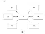
圖2係一例中,此處所述的半導體裝置200的圖式。半導體裝置200包括一或多個電晶體。一或多個電晶體可包括奈米結構電晶體如奈米線電晶體、奈米片電晶體、全繞式閘極電晶體、多橋通道電晶體、奈米帶電晶體、及/或其他種類的奈米結構電晶體。半導體裝置200可包括圖2未顯示的一或多個額外裝置、結構、及/或層狀物。舉例來說,半導體裝置200可包括額外層狀物及/或晶粒形成於圖2所示的半導體裝置200的部分之上及/或之下的層狀物之上。一或多個額外半導體結構及/或半導體裝置可額外或替代地形成於電子裝置或積體電路(其可包括半導體裝置如圖2所示的半導體裝置200)的相同層中。圖3A至11C顯示圖2所示的半導體裝置200的多種部分的剖視圖,且對應形成半導體裝置200的奈米結構電晶體的多種製程階段。FIG. 2 is a diagram of a
半導體裝置200包括半導體基板205。半導體基板205可包括矽基板(由含矽材料所形成的基板)、III-V族半導體材料基板如砷化鎵、絕緣層上矽基板、鍺基板、矽鍺基板、碳化矽基板、或另一種半導體基板。半導體基板205可包括多種層狀物,包括導電或絕緣層形成於半導體基板上。半導體基板205可包括半導體化合物及/或半導體合金。半導體基板205可包括多種摻雜設置以符合一或多個設計參數。舉例來說,可形成不同摻雜輪廓(如n型井或p型井)於設計為用於不同裝置型態(比如p型金氧半奈米結構電晶體或n型金氧半奈米結構電晶體)的區域中的半導體基板205上。合適的摻雜方法可包括離子佈植摻質及/或擴散製程。此外,半導體基板205可包括磊晶層、可具有應力以增進效能、及/或可具有其他合適的增進結構。半導體基板205可包括半導體晶圓的一部分,其上可形成其他半導體裝置。The
台面區210可包含於半導體基板205上及/或延伸高於半導體基板205。台面區210提供結構,其上可形成半導體裝置200的奈米結構如奈米結構通道、包覆每一奈米結構通道的奈米結構閘極部分、及/或犧牲奈米結構。在一些實施方式中,一或多個台面區210可自半導體基板205中的鰭狀結構(如矽鰭狀結構)形成,及/或形成於鰭狀結構中。台面區210可與半導體基板205包括相同材料,且可自半導體基板205形成。在一些實施方式中,可摻雜台面區210以形成不同型態的奈米結構電晶體,比如p型奈米結構電晶體及/或n型奈米結構電晶體。在一些實施方式中,台面區210包括矽材料或另一半導體元素材料如鍺。在一些實施方式中,台面區210包括半導體合金材料如矽鍺、磷砷化鎵、砷化鋁銦、砷化鋁鎵、砷化鎵銦、磷化鎵銦、磷砷化鎵銦、或上述之組合。The
台面區210的製作方法可為合適的半導體製程技術,比如遮罩、光微影、及/或蝕刻製程。舉例來說,鰭狀結構的形成方法可為蝕刻移除半導體基板205的一部分,以形成凹陷於半導體基板205中。接著可將隔離材料填入凹陷,並使隔離材料凹陷或回蝕刻隔離材料,以形成淺溝槽隔離區215於半導體基板205之上與鰭狀結構之間。源極/汲極凹陷可形成於鰭狀結構中,造成台面區210形成於源極/汲極凹陷之間。然而亦可採用其他製作技術以形成淺溝槽隔離區215及/或台面區210。The
淺溝槽隔離區215可與相鄰的鰭狀結構電性隔離,且可提供半導體裝置200的其他層狀物及/或結構形成其上的層狀物。淺溝槽隔離區215可包括介電材料如氧化矽、氮化矽、氮氧化矽、氟矽酸鹽玻璃、低介電常數的介電材料、及/或另一合適的絕緣材料。舉例來說,淺溝槽隔離區215可包括多層結構,比如具有一或多個襯墊層。The shallow
半導體裝置200包括多個奈米結構通道220,其可延伸於源極/汲極區225之間並電性耦接至源極/汲極區225。奈米結構通道220的配置方向近似垂直於半導體基板205。換言之,奈米結構通道220垂直配置或堆疊於半導體基板205上。The
奈米結構通道220包括矽為主的奈米結構(如奈米片或奈米線),其可作為半導體裝置200的奈米結構電晶體的半導體通道。在一些實施方式中,奈米結構通道220可包括矽鍺或另一矽為主的材料。源極/汲極區225包括矽與一或多種摻質如p型材料(如硼或鍺)、n型材料(如磷或砷)、及/或另一型態的摻質。綜上所述,半導體裝置200可包括p型金氧半奈米結構電晶體(其包括p型源極/汲極區225)、n型金氧半奈米結構電晶體(其包括n型源極/汲極區225)、及/或其他型態的奈米結構電晶體。The
在一些實施例中,緩衝區230包含於半導體基板205上的鰭狀結構與源極/汲極區225之間的源極/汲極區225之下。緩衝區230可提供隔離於源極/汲極區225與相鄰的台面區210之間。可包含緩衝區230以減少、最小化、及/或避免電子穿入台面區210 (比如代替穿過奈米結構通道220,進而減少漏電流),及/或減少、最小化、及/或避免摻質自源極/汲極區225進入台面區210 (其可減少短通道效應)。In some embodiments, a
源極/汲極區225之上可包括蓋層235。蓋層235可包括矽、矽鍺、摻雜矽、摻雜矽鍺、及/或另一材料。可包括蓋層235以減少摻質擴散,並在形成接點之前的半導體裝置200所用的半導體製程步驟中保護源極/汲極區225。此外,蓋層235有利於形成金屬-半導體合金(如矽化物)。A
至少一組奈米結構通道220延伸穿過一或多個閘極結構240。閘極結構240的組成可為一或多種金屬材料、一或多種高介電常數的介電材料、及/或一或多種其他種類的材料。在一些實施方式中,虛置閘極結構(如多晶矽閘極結構或另一種閘極結構)形成於閘極結構240的位置(在形成閘極結構240之前),以在形成閘極結構240之前可先形成半導體裝置200的一或多個其他層狀物及/或結構。這可減少及/或避免形成一或多個層狀物及/或結構時對閘極結構240造成的損傷。接著進行置換閘極製程以移除虛置閘極結構,並置換成閘極結構240 (如置換閘極結構)。At least one set of
如圖2所示,閘極結構240的部分以交錯的垂直配置形成於成對的奈米結構通道220之間。換言之,半導體裝置200包括交錯的奈米結構通道220與閘極結構240的部分的一或多個垂直堆疊,如圖2所示。在此方式中,閘極結構240可包覆相關的奈米結構通道220的所有側,以增加對奈米結構通道220的控制、增加半導體裝置200的奈米結構電晶體所用的驅動電流、並減少半導體裝置200的奈米結構電晶體的短通道效應。2, portions of the
半導體裝置200的兩個或更多奈米尺寸的電晶體之間,可共用一些源極/汲極區225與閘極結構240。在這些實施方式中,一或多個源極/汲極區225與閘極結構240可連接或耦接至多個奈米結構通道220,如圖2所示的例子。這可由單一閘極結構240與一對源極/汲極區225控制多個奈米結構通道220。Some source/
內側間隔物245可包含於源極/汲極區225與相鄰的閘極結構240之間。具體而言,內側間隔物245可包含於包覆多個奈米結構通道220的閘極結構240的部分與源極/汲極區225之間。內側間隔物245包含於包覆多個奈米結構通道220的閘極結構240的部分的末端上。內側間隔物245可包含於相鄰的奈米結構通道220的末端部分之間的空洞中。可包含內側間隔物245以減少寄生電容,並在移除奈米結構通道220之間的犧牲奈米片的奈米片釋放步驟中保護源極/汲極區225免於蝕刻。內側間隔物245包括氮化矽、氧化矽、氮氧化矽、碳氧化矽、碳氮化矽、碳氮氧化矽、及/或另一介電材料。The
在一些實施方式中,半導體裝置200包括混合鰭狀結構(未圖示)。混合鰭狀結構亦可視作虛置鰭狀物、混合鰭狀物、或非主動鰭狀物。相鄰的源極/汲極區225之間、閘極結構240的部分之間、及/或相鄰的奈米結構通道220的堆疊之間,可包含混合鰭狀結構。混合鰭狀物的延伸方向近似垂直於閘極結構240。In some embodiments, the
混合鰭狀結構設置以提供電性隔離於半導體裝置200所含的多個結構及或構件之間。在一些實施方式中,混合鰭狀結構設置以提供電性隔離於奈米結構通道220的多個堆疊之間。在一些實施方式中,混合鰭狀結構設置以提供電性隔離於多個源極/汲極區225之間。在一些實施方式中,混合鰭狀結構設置以提供電性隔離於多個閘極結構或閘極結構的多個部分之間。在一些實施方式中,混合鰭狀結構設置以提供電性隔離於源極/汲極區225與閘極結構240之間。The hybrid fin structure is configured to provide electrical isolation between multiple structures and or components included in the
混合鰭狀結構可包括多種介電材料。混合鰭狀結構可包括一或多種低介電常數的介電材料(如氧化矽及/或氮化矽)與一或多種高介電常數的介電材料(如氧化鉿及/或其他高介電常數的介電材料)的組合。The hybrid fin structure may include a variety of dielectric materials. The hybrid fin structure may include a combination of one or more low-k dielectric materials (such as silicon oxide and/or silicon nitride) and one or more high-k dielectric materials (such as bismuth oxide and/or other high-k dielectric materials).
半導體裝置200亦可包括層間介電層250位於淺溝槽隔離區215上。層間介電層250可視作第零層間介電層。層間介電層250可圍繞閘極結構240,以提供電性隔離及/或絕緣於閘極結構240及/或源極/汲極區225之間。形成導電結構如接點及/或內連線以穿過層間介電層250至源極/汲極區225與閘極結構240,可提供源極/汲極區225與閘極結構240的控制。The
半導體裝置200可包括區域與結構的不同組合。以圖3A至11C所示與其他處說明的內容為例,半導體裝置200可包括n型金氧半奈米結構電晶體與p型金氧半奈米結構電晶體。n型金氧半奈米結構電晶體可包括多個第一奈米結構通道220於半導體基板205上。多個第一奈米結構通道220的配置方向可垂直於半導體基板205。在一些實施方式中,多個第一奈米結構通道220之一可包括第一寬度。n型金氧半奈米結構電晶體亦可包括第一閘極結構240包覆多個第一奈米結構通道的每一者。p型金氧半奈米結構電晶體可包括多個第二奈米結構通道220於半導體基板205上。多個第二奈米結構通道220的配置方向可垂直於半導體基板205。在一些實施方式中,多個第二奈米結構通道220之一可包括第二寬度。p型金氧半奈米結構電晶體亦可包括第二閘極結構240以包覆多個第二奈米結構通道220的每一者。The
半導體裝置200可額外或替代地包括第一裝置種類所用的第一奈米結構電晶體。第一奈米結構電晶體可包括多個第一奈米結構通道220於半導體基板205上。多個第一奈米結構通道220的配置方向可垂直於半導體基板205。第一奈米結構電晶體可更包括第一閘極結構240以包覆多個第一奈米結構通道220的每一者。半導體裝置200亦可包括第二裝置種類所用的第二奈米結構。第二奈米結構電晶體可包括多個第二奈米結構通道220於半導體基板205上。多個第二奈米結構通道220的配置方向可垂直於半導體基板205。第二奈米結構電晶體亦可包括第二閘極結構240包覆多個第二奈米結構通道220的每一者。The
如上所述,提供圖2以作為例子。其他例子可不同於圖2所述的內容。As mentioned above, FIG. 2 is provided as an example. Other examples may differ from what is described in FIG. 2 .
圖3A及3B係一例中,此處所述的鰭狀物形成製程的實施方式300的圖式。實施方式300的例子包括形成鰭狀結構以用於半導體裝置200或其部分。半導體裝置200可包括圖3A及3B未圖示的一或多個額外裝置、結構、及/或層狀物。半導體裝置200可包括額外層狀物及/或晶粒形成於圖3A及3B所示的半導體裝置200的部分之上及/或之下的層狀物之上。一或多個額外半導體結構及/或半導體裝置可額外或替代地形成於電子裝置 (其可包括半導體裝置200)的相同層中。FIGS. 3A and 3B are diagrams of an embodiment 300 of a fin formation process described herein, in one example. An example of embodiment 300 includes forming a fin structure for use with
圖3A顯示半導體裝置200的透視圖與沿著透視圖中的剖面A-A的剖視圖。如圖3A所示,可對半導體裝置200進行與半導體基板205相關的製程。層狀堆疊305形成於半導體基板205上。層狀堆疊305可視作超晶格。在一些實施方式中,可在形成層狀堆疊305之前,進行與半導體基板205相關的一或多個步驟。舉例來說,可進行抗擊穿佈植的步驟。舉例來說,可在半導體基板205的一或多個區域中進行抗擊穿佈植的步驟,而奈米結構通道220可形成於區域上。舉例來說,進行抗擊穿佈植步驟以減少及/或避免擊穿或不想要的擴散至半導體基板205中。FIG3A shows a perspective view of a
層狀堆疊305包括多個交錯的層狀物,其配置方向近似垂直於半導體基板205。舉例來說,層狀堆疊305包括垂直交錯的第一層310與第二層315位於半導體基板205上。圖3A所示的第一層310的數目與第二層315的數目用於舉例,且第一層310的其他數目與第二層315的其他數目亦屬本發明實施例的範疇。在一些實施方式中,第一層310與第二層315可具有不同厚度。舉例來說,第二層315的厚度可大於第一層310的厚度。在一些實施方式中,第一層310 (或一組第一層310)的厚度可為近似4 nm至近似7 nm。在一些實施方式中,第二層315 (或一組第二層315)的厚度可為近似8 nm至近似12 nm。然而第一層310的厚度與第二層315的厚度的其他數值亦屬本發明實施例的範疇。The layer stack 305 includes a plurality of staggered layers, and the configuration direction thereof is approximately perpendicular to the
第一層310包括第一材料組成,且第二層315包括第二材料組成。在一些實施方式中,第一材料組成與第二材料組成為相同的材料組成。在一些實施方式中,第一材料組成與第二材料組成為不同的材料組成。舉例來說,第一層310可包括矽鍺而第二層315可包括矽。在一些實施方式中,第一材料組成與第二材料組成可具有不同的氧化速率及/或蝕刻選擇性。The first layer 310 includes a first material composition, and the second layer 315 includes a second material composition. In some embodiments, the first material composition and the second material composition are the same material composition. In some embodiments, the first material composition and the second material composition are different material compositions. For example, the first layer 310 may include silicon germanium and the second layer 315 may include silicon. In some embodiments, the first material composition and the second material composition may have different oxidation rates and/or etching selectivities.
如此處所述,可處理第二層315以形成半導體裝置200的之後形成的奈米結構電晶體所用的奈米結構通道220。第一層310為犧牲奈米結構,最終將移除且可定義相鄰奈米結構通道220之間的垂直距離,其用於半導體裝置200的之後形成的閘極結構240。綜上所述,第一層310可是做犧牲層,而第二層315可視作通道層。As described herein, the second layer 315 may be processed to form a
沉積工具102沉積及/或成長層狀堆疊305的交錯層狀物,以包括奈米結構(如奈米片)於半導體基板205上。舉例來說,沉積工具102磊晶成長交錯的層狀物。然而亦可採用其他製程形成層狀堆疊305的交錯層狀物。磊晶成長層狀堆疊305的交錯層狀物的方法,可為分子束磊晶製程、有機金屬化學氣相沉積製程、及/或另一合適的磊晶成長製程。在一些實施方式中,磊晶成長的層狀物如第二層315包括的材料可與半導體基板205的材料相同。在一些實施方式中,第一層310及/或第二層315包括的材料可與半導體基板205的材料不同。如上所述,一些實施方式中的第一層310包括磊晶成長的矽鍺層,而第二層315包括磊晶成長的矽層。第一層310及/或第二層315可改為包含其他材料如鍺、半導體化合物材料(如碳化矽、砷化鎵、磷化鎵、磷化銦、砷化銦、或銻化銦)、半導體合金(如矽鍺、磷砷化鎵、砷化鋁銦、砷化鋁鎵、砷化鎵銦、磷化鎵銦、或磷砷化鎵銦)、及/或上述之組合。第一層310的材料及/或第二層315的材料選擇可提供不同的氧化特性、不同的蝕刻選擇性、及/或其他不同特性。The
如圖3A所示,沉積工具102可形成一或多個額外層狀物於層狀堆疊305上。舉例來說,可形成硬遮罩層320於層狀堆疊305之上,比如形成於層狀堆疊305的最頂部的第二層315上。在另一例中,蓋層325可形成於硬遮罩層320上。在另一例中,含有氧化物層330與氮化物層335的另一硬遮罩層可形成於蓋層325上。一或多個硬遮罩層320、蓋層325、與氧化物層330可用於形成半導體裝置200的一或多個結構。氧化物層330可作為層狀堆疊305與氮化物層335之間的黏著層,亦可作為蝕刻氮化物層335所用的蝕刻停止層。一或多個硬遮罩層320、蓋層325、與氧化物層330可包括矽鍺、氮化矽、氧化矽、及/或另一材料。蓋層325可包括矽及/或另一材料。在一些實施方式中,蓋層325與半導體基板205的組成可為相同材料。在一些實施方式中,一或多個額外層的形成方法可為熱成長或沉積(如化學氣相沉積、物理氣相沉積、原子層沉積、及/或另一沉積技術)。As shown in FIG3A , the
圖3B顯示半導體裝置200的透視圖與沿著剖面A-A的剖視圖。如圖3B所示,蝕刻層狀堆疊305與半導體基板205以移除層狀堆疊305的部分與半導體基板205的部分。在蝕刻步驟之後保留的層狀堆疊305的部分340與台面部分(亦可視作台面區210),可視作半導體裝置200的半導體基板205上的鰭狀結構345。鰭狀結構345包括層狀堆疊305的部分340位於半導體基板205之中及/或之上的台面區210上。鰭狀結構345的形成方法可為任何合適的半導體製程技術。舉例來說,沉積工具102、曝光工具104、顯影工具106、及/或蝕刻工具108可採用一或多道光微影製程形成鰭狀結構345,包括雙重圖案化或多重圖案化製程。一般而言,雙重圖案化或多重圖案化製程可結合光微影與自對準製程,其產生的圖案間距小於採用單一的直接光微影製程所得的圖案間距。舉例來說,可形成犧牲層於基板上,並採用光微影製程圖案化犧牲層。可採用自對準製程以沿著圖案化的犧牲層側部形成間隔物。接著移除犧牲層,而保留的間隔物之後可用於圖案化鰭狀結構。3B shows a perspective view and a cross-sectional view along the cross section A-A of the
在一些實施方式中,沉積工具102形成光阻層於含有氧化物層330與氮化物層335的硬遮罩層上,曝光工具104曝光光阻層至射線(如深紫外線或極紫外線),進行曝光後烘烤製程(以自光阻層移除殘留溶劑),而顯影工具106顯影光阻層以形成遮罩單元(或圖案)於光阻層中。在一些實施方式中,圖案化光阻層以形成遮罩單元的方法可採用電子束微影製程。接著可在蝕刻步驟中採用遮罩單元保護半導體基板205的部分與層狀堆疊305的部分,使半導體基板205的部分與層狀堆疊305的部分維持未蝕刻以形成鰭狀結構345。可由蝕刻工具108蝕刻基板的未保護部分與層狀堆疊305的未保護部分,以形成溝槽於半導體基板205中。蝕刻工具可採用乾蝕刻技術(如反應性離子蝕刻)、濕蝕刻技術、及/或上述之組合,以蝕刻基板的未保護部分與層狀堆疊305的未保護部分。In some embodiments, the
在一些實施方式中,可採用另一鰭狀物形成技術以形成鰭狀結構345。舉例來說,可由遮罩與隔離區定義鰭狀物區,且可以鰭狀結構345的形式磊晶成長部分340。在一些實施方式中,形成鰭狀結構345的方法包括修整製程以減少鰭狀結構345的寬度。修整製程可包括濕蝕刻製程及/或乾蝕刻製程。In some embodiments, another fin formation technique may be used to form the fin structure 345. For example, the fin region may be defined by a mask and an isolation region, and the portion 340 may be epitaxially grown in the form of the fin structure 345. In some embodiments, the method of forming the fin structure 345 includes a trimming process to reduce the width of the fin structure 345. The trimming process may include a wet etching process and/or a dry etching process.
如圖3B所示,可形成鰭狀結構345以用於半導體裝置200所用的不同型態的奈米結構電晶體。具體而言,可形成第一組鰭狀結構345a以用於p型奈米結構電晶體(如p型金氧半奈米結構電晶體),且可形成第二組鰭狀結構345b以用於n型奈米結構電晶體(如n型金氧半奈米結構電晶體)。第二組鰭狀結構345b可摻雜p型摻質(如硼及/或鍺),而第一組鰭狀結構345a可摻雜n型摻質(如磷及/或砷)。之後可額外或替代地形成p型源極/汲極區225以用於p型奈米結構電晶體,其可包括第一組鰭狀結構345a;且可形成n型源極/汲極區225以用於n型奈米結構電晶體,其可包括第二組鰭狀結構345b。As shown in FIG3B , fin structures 345 may be formed for use in different types of nanostructured transistors used in
第一組鰭狀結構345a (如p型金氧半鰭狀結構)與第二組鰭狀結構345b (如n型金氧半鰭狀結構)可包含類似特性及/或不同特性。舉例來說,第一組鰭狀結構345a可具有第一高度,第二組鰭狀結構345b可具有第二高度,且第一高度不同於第二高度。在另一例中,第一組鰭狀結構345a可為第一寬度,第二組鰭狀結構345b可為第二寬度,且第一寬度不同於第二寬度。在圖3B所示的例子中,第二組鰭狀結構345b (比如用於n型金氧半奈米結構電晶體)的第二寬度,大於第一組鰭狀結構345a (比如用於p型金氧半奈米結構電晶體)的第一寬度。然而其他例子亦屬本發明實施例的範疇。The first set of fin structures 345a (e.g., p-type metal oxide semiconductor fin structures) and the second set of fin structures 345b (e.g., n-type metal oxide semiconductor fin structures) may include similar characteristics and/or different characteristics. For example, the first set of fin structures 345a may have a first height, the second set of fin structures 345b may have a second height, and the first height is different from the second height. In another example, the first set of fin structures 345a may have a first width, the second set of fin structures 345b may have a second width, and the first width is different from the second width. In the example shown in FIG3B , the second width of the second set of fin structures 345b (eg, for n-type MOS transistors) is greater than the first width of the first set of fin structures 345a (eg, for p-type MOS transistors). However, other examples also fall within the scope of embodiments of the present invention.
第一組鰭狀結構(如p型金氧半鰭狀結構)可用於裝置種類,比如靜態隨機存取記憶體裝置種類、環形振盪器裝置種類、或輸入/輸出裝置種類。如圖11A至11C所示的內容,第一組鰭狀結構的尺寸特性可隨裝置種類變化。此外,第二組鰭狀結構(如n型金氧半鰭狀結構)可用於裝置種類,比如靜態隨機存取記憶體裝置種類、環形振盪器裝置種類、或輸入/輸出裝置種類。如圖11A至11C所示的內容,第二組鰭狀結構的尺寸特性可隨裝置種類變化。The first set of fin structures (e.g., p-type metal oxide semiconductor fin structures) can be used for device types, such as static random access memory device types, ring oscillator device types, or input/output device types. As shown in Figures 11A to 11C, the size characteristics of the first set of fin structures can vary with the device type. In addition, the second set of fin structures (e.g., n-type metal oxide semiconductor fin structures) can be used for device types, such as static random access memory device types, ring oscillator device types, or input/output device types. As shown in Figures 11A to 11C, the size characteristics of the second set of fin structures can vary with the device type.
如上所述,提供圖3A及3B以作為例子。其他例子可不同於圖3A及3B所示的例子。例示性的實施方式300可包括額外步驟、較少步驟、不同步驟、及/或不同於圖3A及3B所示的步驟順序。As described above, Figures 3A and 3B are provided as examples. Other examples may differ from the examples shown in Figures 3A and 3B. The exemplary implementation 300 may include additional steps, fewer steps, different steps, and/or a different order of steps than shown in Figures 3A and 3B.
圖4A及4B係一例中,此處所述的淺溝槽隔離形成製程的實施方式400的圖式。實施方式400的例子可包括形成淺溝槽隔離區215於鰭狀結構345之間,以用於半導體裝置200或其部分。半導體裝置200可包括圖4A及4B未圖示的一或多個額外裝置、結構、及/或層狀物。半導體裝置200可包括額外層狀物及/或晶粒形成於圖4A及4B所示的半導體裝置200的部分之上及/或之下的層狀物之上。一或多個額外半導體結構及/或半導體裝置可額外或替代地形成於電子裝置 (其可包括半導體裝置200)的相同層中。在一些實施方式中,可在進行圖3A及3B所示的製程之後,進行實施方式400相關的步驟。FIGS. 4A and 4B are diagrams of an embodiment 400 of a shallow trench isolation formation process described herein, in one example. An example of embodiment 400 may include forming a shallow
圖4A顯示半導體裝置200的透視圖與沿著剖面A-A的剖視圖。如圖4A所示,襯墊405與介電層410形成於半導體基板205上並插入鰭狀結構345 (比如位於鰭狀結構345之間)。沉積工具102可沉積襯墊405與介電層410於半導體基板205之上以及鰭狀結構345之間的溝槽之中。沉積工具102形成的介電層410的上表面高度與氮化物層335的上表面高度可為近似相同的高度。4A shows a perspective view and a cross-sectional view along the cross section A-A of the
在其他實施例中,沉積工具102形成的介電層410的上表面高度可大於氮化物層335的上表面高度,如圖4A所示。在此方式中,可將介電層410超填鰭狀結構345之間的溝槽,以確保介電層410完全填入溝槽。平坦化工具110之後可進行平坦化或研磨步驟(如化學機械研磨步驟),以平坦化介電層410。硬遮罩層的氮化物層335可作為步驟中的化學機械研磨停止層。換言之,平坦化工具110平坦化介電層410,直到達到硬遮罩層的氮化物層335。綜上所述,步驟之後的介電層410的上表面高度可近似等於氮化物層335的上表面高度。In other embodiments, the top surface height of the dielectric layer 410 formed by the
沉積工具102可採用順應性的沉積技術沉積襯墊405。沉積工具102可採用化學氣相沉積技術(如可流動的化學氣相沉積技術或另一化學氣相沉積技術)、物理氣相沉積技術、原子層沉積技術、及/或另一沉積技術沉積介電層。在一些實施方式中,沉積襯墊405之後可退火半導體裝置200,以增加襯墊405的品質。The
襯墊405與介電層410各自包括介電材料如氧化矽、氮化矽、氮氧化矽、氟矽酸鹽玻璃、低介電常數的介電材料、及/或另一合適的絕緣材料。在一些實施方式中,介電層410可包括多層結構,比如具有一或多個襯墊層。The pad 405 and the dielectric layer 410 each include a dielectric material such as silicon oxide, silicon nitride, silicon oxynitride, fluorosilicate glass, a low-k dielectric material, and/or another suitable insulating material. In some embodiments, the dielectric layer 410 may include a multi-layer structure, such as having one or more pad layers.
圖4B顯示半導體裝置200的透視圖與沿著剖面A-A的剖視圖。如圖4B所示,進行回蝕刻步驟以移除襯墊405的部分與介電層410的部分而形成淺溝槽隔離區215。蝕刻工具108可在回蝕刻步驟中蝕刻襯墊405與介電層410,以形成淺溝槽隔離區215。蝕刻工具108可依據硬遮罩層(比如含氧化物層330與氮化物層335的硬遮罩層)蝕刻襯墊405與介電層410。蝕刻工具108可蝕刻襯墊405與介電層410,使淺溝槽隔離區215的高度小於或近似等於層狀堆疊305的部分340的底部高度。綜上所述,層狀堆疊305的部分340延伸高於淺溝槽隔離區215。在一些實施方式中,蝕刻襯墊405與介電層410,使淺溝槽隔離區215的高度小於台面區210的上表面的高度。4B shows a perspective view and a cross-sectional view along the cross section A-A of the
在一些實施方式中,蝕刻工具108採用電漿為主的乾蝕刻技術以蝕刻襯墊405與介電層410。可採用氨、氫氟酸、及/或另一蝕刻劑。電漿為主的乾蝕刻技術可造成蝕刻劑與襯墊405及介電層410的材料之間的反應,比如: SiO2+ 4HF → SiF4+ 2H2O 其中襯墊405與介電層410的氧化矽與氫氟酸反應形成副產物如四氟化矽與水。氫氟酸與氨可使四氟化矽進一步斷鍵以形成氟矽酸銨副產物,比如: SiF4+ 2HF + 2NH3→ (NH4)2SiF6可由蝕刻工具108的製程腔室移除氟矽酸銨副產物。在移除氟矽酸銨之後,可採用後製程溫度如近似200℃至近似250℃以昇華氟矽酸銨成四氟化矽、氨、與氫氟酸。In some embodiments, the
在一些實施例中,蝕刻工具108蝕刻襯墊405與介電層410,使第一組鰭狀結構345a (比如用於p型金氧半奈米結構電晶體)之間的淺溝槽隔離區215的高度,大於第二組鰭狀結構345b (比如用於n型金氧半奈米結構電晶體)之間的淺溝槽隔離區215的高度。上述現象的主因為鰭狀結構345b的寬度大於鰭狀結構345a的寬度。此外,這造成鰭狀結構345a與鰭狀結構345b之間的淺溝槽隔離區215的上表面傾斜或斜向(比如自鰭狀結構345a朝鰭狀結構345b向下傾斜,如圖4A所示的例子)。蝕刻劑與襯墊405及介電層410的表面之間的凡得瓦力,造成蝕刻襯墊405與介電層410的蝕刻劑先物理吸附(比如物理鍵結至襯墊405與介電層410)。偶極矩力可捕獲蝕刻劑。蝕刻劑接著貼附至襯墊405與介電層410的懸吊鍵而開始化學吸附。蝕刻劑化學吸附至襯墊405與介電層410的表面上,造成襯墊405與介電層410的蝕刻。第二組鰭狀結構345b之間的溝槽寬度較大,可提供較大表面積以產生化學吸附,造成第二組鰭狀結構345b之間的蝕刻速率較大。較大的蝕刻速率造成第二組鰭狀結構345b之間的淺溝槽隔離區215的高度,小於第一組鰭狀結構345a之間的淺溝槽隔離區215的高度。In some embodiments, the
如上所述,提供圖4A及4B以作為例子。其他例子可不同於圖4A及4B所示的例子。例示性的實施方式400可包括額外步驟、較少步驟、不同步驟、及/或不同於圖4A及4B所示的步驟順序。As described above, Figures 4A and 4B are provided as examples. Other examples may differ from the examples shown in Figures 4A and 4B. The exemplary implementation 400 may include additional steps, fewer steps, different steps, and/or a different order of steps than shown in Figures 4A and 4B.
圖5A至5C係一例中,此處所述的覆層側壁製程的實施方式500的圖式。例示性的實施方式500包括形成覆層側壁於層狀堆疊305的部分340的側壁上,以用於半導體裝置200或其部分。半導體裝置200可包括圖5A至5C未圖示的一或多個額外裝置、結構、及/或層狀物。半導體裝置200可包括額外層狀物及/或晶粒形成於圖5A至5C所示的半導體裝置200的部分之上及/或之下的層狀物之上。一或多個額外半導體結構及/或半導體裝置可額外或替代地形成於電子裝置 (其可包括半導體裝置200)的相同層中。在一些實施方式中,可在進行圖3A至4B所示的製程之後,進行實施方式500相關的步驟。FIGS. 5A-5C are diagrams of an embodiment 500 of a coating sidewall process described herein, in one example. Exemplary embodiment 500 includes forming a coating sidewall on a sidewall of a portion 340 of a layered stack 305 for a
圖5A顯示半導體裝置200的透視圖與沿著剖面A-A的剖視圖。如圖5A所示,覆層505形成於鰭狀結構345上(比如鰭狀結構345的上表面與側壁上)與鰭狀結構345之間的淺溝槽隔離區215上。覆層505包括矽鍺或另一材料。覆層505與第一層310的組成可為相同材料,使相同的蝕刻步驟(如奈米結構釋放製程)可同時移除覆層側壁(自覆層505形成)與第一層310,因此置換閘極(如閘極結構240)可形成於覆層側壁與第一層310原本占據的區域中。這可使置換閘極完全圍繞半導體裝置200的奈米結構電晶體的奈米結構通道。5A shows a perspective view and a cross-sectional view along section A-A of
沉積工具102可沉積覆層505。在一些實施方式中,沉積工具102沉積晶種層(如矽晶種層或另一種晶種層)於鰭狀結構345上(比如鰭狀結構345的上表面與側壁上)與鰭狀結構345之間的淺溝槽隔離區215上。沉積工具102接著沉積矽鍺於晶種層上,以形成覆層505。晶種層可促進覆層505的成長與黏著性。The
沉積晶種層的方法可包括採用載氣如氮氣或氫氣提供矽前驅物至沉積工具102的製程腔室。在一些實施方式中,可在沉積晶種層之前進行預清潔步驟,以減少形成氧化鍺。矽前驅物可包括乙矽烷或另一矽前驅物。採用乙矽烷可形成厚度為近似0.5 nm至近似1.5 nm的晶種層,以提供足夠厚度的覆層側壁,且覆層505具有可控且一致的厚度。然而晶種層厚度的其他範圍與數值亦屬本發明實施例的範疇。The method of depositing the seed layer may include providing a silicon precursor to a process chamber of the
沉積晶種層的溫度可為近似450℃至近似500℃ (或另一範圍的溫度),壓力可為近似30 torr至近似100 torr (或另一範圍的壓力),及/或時間可為近似100秒至近似300秒(或另一範圍的時間)。The temperature of depositing the seed layer may be approximately 450° C. to approximately 500° C. (or another range of temperatures), the pressure may be approximately 30 torr to approximately 100 torr (or another range of pressures), and/or the time may be approximately 100 seconds to approximately 300 seconds (or another range of times).
沉積覆層505的矽鍺包括形成覆層505,以包括非晶質地而促進順應性沉積覆層505。矽鍺的鍺含量可為近似15%至近似25%。然而鍺含量的其他數值亦屬本發明實施例的範疇。沉積覆層505的步驟可包括採用載氣(如氮氣或氫氣)提供矽前驅物(如乙矽烷或矽烷)與鍺前驅物(如鍺烷或另一鍺前驅物)到沉積工具102的製程腔室,沉積覆層505的溫度可為近似500℃至近似550℃ (或另一範圍的溫度),及/或壓力可為近似5 torr至近似20 torr (或另一範圍的壓力)。Depositing the silicon germanium capping layer 505 includes forming the capping layer 505 to include an amorphous texture to facilitate conformal deposition of the capping layer 505. The silicon germanium may have a germanium content of approximately 15% to approximately 25%. However, other values of the germanium content are also within the scope of embodiments of the present invention. The step of depositing the coating 505 may include providing a silicon precursor (e.g., disilane or silane) and a germanium precursor (e.g., germanium ane or another germanium precursor) to a process chamber of the
圖5B顯示半導體裝置200的透視圖與沿著剖面A-A的剖視圖。如圖5B所示,進行回蝕刻步驟以蝕刻覆層505而形成覆層側壁510。蝕刻工具108可採用電漿為主的乾蝕刻技術或另一蝕刻技術以蝕刻覆層505。蝕刻工具108可進行回蝕刻步驟以自鰭狀結構345的頂部與淺溝槽隔離區215的頂部移除覆層505的部分。自鰭狀結構345之間的淺溝槽隔離區215的頂部移除覆層505,可確保覆層側壁510不含腳位於鰭狀結構345之間的淺溝槽隔離區215上。這可確保覆層側壁510不含腳位於混合鰭狀結構(其將形成於鰭狀結構345之間的淺溝槽隔離區215上)之下。5B shows a perspective view and a cross-sectional view along the cross section A-A of the
在一些實施方式中,蝕刻工具108採用氟為主的蝕刻劑以蝕刻覆層505。氟為主的蝕刻劑可包括六氟化硫、氟化甲烷、及/或另一氟為主的蝕刻劑。回蝕刻步驟中可採用其他反應物及/或載氣如甲烷、氫氣、氬氣、及/或氦氣。在一些實施方式中,回蝕刻步驟採用的偏置電漿可為近似500伏特至近似2000伏特。然而偏置電漿的其他數值亦屬本發明實施例的範疇。在一些實施方式中,自淺溝槽隔離區215的頂部移除覆層505的部分,可包括進行高方向性(如非等向)蝕刻以選擇性移除(如選擇性蝕刻)鰭狀結構345之間的淺溝槽隔離區215的頂部上的覆層505。In some embodiments, the
在一些實施方式中,覆層側壁510包括不對稱的特性(比如不同長度、深度、及/或角度)。不對稱的特性可增加不同種類的奈米結構電晶體(比如p型奈米結構電晶體與n型奈米結構電晶體)所用的閘極結構240的深度,並減少及/或最小化半導體裝置200的奈米結構電晶體的混合鰭狀結構之下的淺溝槽隔離區215上的覆層側壁510的腳位,因此減少及/或最小化移除覆層側壁510之後形成的閘極結構240的腳位(閘極結構240形成於覆層側壁510原本占據的區域中)。減少及/或最小化腳位,可進一步減少電性短路及/或漏電流。In some embodiments, the cladding sidewall 510 includes asymmetric features (e.g., different lengths, depths, and/or angles). The asymmetric features can increase the depth of the
圖5C顯示半導體裝置200的透視圖與沿著剖面A-A的剖視圖。如圖5C所示,移除硬遮罩層(含氧化物層330與氮化物層335)與蓋層325以露出硬遮罩層320。在一些實施方式中,可由蝕刻工具108進行蝕刻步驟、可由平坦化工具110進行平坦化技術、及/或採用另一半導體製程技術,以移除蓋層325、氧化物層330、與氮化物層335。5C shows a perspective view and a cross-sectional view along the cross section A-A of the
如上所述,提供圖5A至5C以作為例子。其他例子可不同於圖5A至5C所示的例子。例示性的實施方式500可包括額外步驟、較少步驟、不同步驟、及/或不同於圖5A至5C所示的步驟順序。As described above, Figures 5A to 5C are provided as examples. Other examples may differ from the examples shown in Figures 5A to 5C. The exemplary implementation 500 may include additional steps, fewer steps, different steps, and/or a different order of steps than shown in Figures 5A to 5C.
圖6A至6C係一例中,此處所述的混合鰭狀結構的形成製程的實施方式600的圖式。實施方式600的例子可包括形成混合鰭狀結構於鰭狀結構345之間,以用於半導體裝置200或其部分。半導體裝置200可包括圖6A至6C未圖示的一或多個額外裝置、結構、及/或層狀物。半導體裝置200可包括額外層狀物及/或晶粒形成於圖6A至6C所示的半導體裝置200的部分之上及/或之下的層狀物之上。一或多個額外半導體結構及/或半導體裝置可額外或替代地形成於電子裝置 (其可包括半導體裝置200)的相同層中。在一些實施方式中,可在進行圖3A至5C所示的製程之後,進行實施方式600相關的步驟。FIGS. 6A-6C are diagrams of an embodiment 600 of a process for forming a hybrid fin structure as described herein, in one example. An example of embodiment 600 may include forming a hybrid fin structure between fin structures 345 for use in
圖6A顯示半導體裝置200的透視圖與沿著剖面A-A的剖視圖。如圖6A所示,襯墊605與介電層610形成於鰭狀結構345之間的淺溝槽隔離區215 (其可插入鰭狀結構345)之上,以及鰭狀結構345之上。沉積工具102可沉積襯墊605與介電層610。沉積工具102可採用順應性沉積技術以沉積襯墊605。沉積工具102沉積介電層610的方法可採用化學氣相沉積技術(如可流動的化學氣相沉積技術或另一化學氣相沉積技術)、物理氣相沉積技術、原子層沉積技術、及/或另一沉積技術。在一些實施方式中,沉積介電層610之後可退火半導體裝置200,以增加介電層610的品質。6A shows a perspective view and a cross-sectional view along section A-A of
沉積工具102可形成介電層610,使介電層610的上表面的高度與硬遮罩層320的上表面的高度近似相同。在其他實施例中,沉積工具102可形成介電層610,使介電層610的高度大於硬遮罩層320的上表面的高度,如圖6A所示的例子。在此方式中,介電層610可超填鰭狀結構345之間的溝槽,以確保介電層610完全填入溝槽。平坦化工具110之後可進行平坦化或研磨步驟(如化學機械研磨步驟)以平坦化介電層610。The
襯墊605與介電層610各自包括介電材料如氧化矽、氮化矽、氮氧化矽、碳氮化矽、氟矽酸鹽玻璃、低介電常數的介電材料、及/或另一合適的絕緣材料。在一些實施方式中,介電層610可包括多層結構,比如具有一或多個襯墊層。The pad 605 and the dielectric layer 610 each include a dielectric material such as silicon oxide, silicon nitride, silicon oxynitride, silicon carbonitride, fluorosilicate glass, a low-k dielectric material, and/or another suitable insulating material. In some embodiments, the dielectric layer 610 may include a multi-layer structure, such as having one or more pad layers.
圖6B係半導體裝置200的透視圖與沿著剖面A-A的剖視圖。如圖6B所示,進行回蝕刻步驟以移除介電層610的部分。蝕刻工具108可在回蝕刻步驟中蝕刻介電層610,以減少介電層610的上表面的高度。具體而言,蝕刻工具108可蝕刻介電層610,使鰭狀結構345之間的介電層610的部分的高度小於硬遮罩層320的上表面的高度。在一些實施方式中,蝕刻工具108蝕刻介電層610,使鰭狀結構345之間的介電層610的部分的高度,近似等於部分340的最頂部的第二層315的上表面的高度。6B is a perspective view and a cross-sectional view along the cross section A-A of the
圖6C顯示半導體裝置200的透視圖與沿著剖面A-A的剖視圖。如圖6C所示,高介電常數層615沉積於鰭狀結構345之間的介電層610的部分上。沉積工具102可沉積高介電常數的材料如氧化鉿及/或另一高介電常數的介電材料以形成高介電常數層615,其形成方法可採用化學氣相沉積技術、物理氣相沉積技術、原子層沉積技術、及/或另一沉積技術。鰭狀結構345之間的介電層610的部分與鰭狀結構345之間的高介電常數層615的組合,可視作混合鰭狀結構620 (或虛置鰭狀結構)。在一些實施方式中,平坦化工具110可進行平坦化步驟以平坦化高介電常數層615,使高介電常數層615的上表面高度近似等於硬遮罩層320的高度。6C shows a perspective view and a cross-sectional view along section A-A of the
之後如圖6C所示,可移除硬遮罩層320。移除硬遮罩層320的方法可採用蝕刻技術(比如電漿蝕刻技術、濕式化學蝕刻技術、及/或另一種蝕刻技術)或另一移除技術。6C , the hard mask layer 320 may be removed. The hard mask layer 320 may be removed by an etching technique (such as a plasma etching technique, a wet chemical etching technique, and/or another etching technique) or another removal technique.
如上所述,提供圖6A至6C以作為例子。其他例子可不同於圖6A至6C所示的例子。例示性的實施方式600可包括額外步驟、較少步驟、不同步驟、及/或不同於圖6A至6C所示的步驟順序。As described above, Figures 6A to 6C are provided as examples. Other examples may differ from the examples shown in Figures 6A to 6C. The exemplary implementation 600 may include additional steps, fewer steps, different steps, and/or a different order of steps than shown in Figures 6A to 6C.
圖7A及7B係一例中,此處所述的虛置閘極形成製程的實施方式700的圖式。實施方式700的例子可包括形成虛置閘極結構以用於半導體裝置200或其部分。半導體裝置200可包括圖7A及7B未圖示的一或多個額外裝置、結構、及/或層狀物。半導體裝置200可包括額外層狀物及/或晶粒形成於圖7A及7B所示的半導體裝置200的部分之上及/或之下的層狀物之上。一或多個額外半導體結構及/或半導體裝置可額外或替代地形成於電子裝置 (其可包括半導體裝置200)的相同層中。在一些實施方式中,可在進行圖3A至6C所示的製程之後,進行實施方式700相關的步驟。FIGS. 7A and 7B are diagrams of an implementation 700 of a dummy gate formation process described herein, in one example. An example of implementation 700 may include forming a dummy gate structure for use with
圖7A顯示半導體裝置200的透視圖。如圖7A所示,虛置閘極結構705 (亦可視作虛置閘極堆疊或暫時閘極結構)形成於鰭狀結構345與混合鰭狀結構620上。虛置閘極結構705為犧牲結構,其將於半導體裝置200所用的後續製程階段中,置換為置換閘極結構或置換閘極堆疊(如閘極結構240)。虛置閘極結構705之下的鰭狀結構345的部分可視作通道區。虛置閘極結構705亦可定義鰭狀結構345的源極/汲極區,比如鰭狀結構345與通道區相鄰且位於通道區兩側上的區域。7A shows a perspective view of the
虛置閘極結構705可包括閘極層710、硬遮罩層715位於閘極層710上、與間隔物層720位於閘極層710的兩側與硬遮罩層715的兩側上。虛置閘極結構705可形成於最頂部的第二層315與虛置閘極結構705之間以及混合鰭狀結構620與虛置閘極結構705之間的的閘極介電層725上。閘極層710包括多晶矽或另一材料。硬遮罩層715包括一或多層如氧化物層(如墊氧化物層,其可包括氧化矽或另一材料)與氮化物層(如墊氮化物層,其可包括氮化矽或另一材料)形成於氧化物層上。間隔物層720包括碳氧化矽、無氮的碳氧化矽、或另一合適材料。閘極介電層725可包括氧化矽、氮化矽、高介電常數的介電材料、及/或另一合適材料。The dummy gate structure 705 may include a gate layer 710, a hard mask layer 715 on the gate layer 710, and a spacer layer 720 on both sides of the gate layer 710 and the hard mask layer 715. The dummy gate structure 705 may be formed on a gate dielectric layer 725 between the top second layer 315 and the dummy gate structure 705 and between the hybrid fin structure 620 and the dummy gate structure 705. The gate layer 710 includes polysilicon or another material. The hard mask layer 715 includes one or more layers such as an oxide layer (such as a pad oxide layer, which may include silicon oxide or another material) and a nitride layer (such as a pad nitride layer, which may include silicon nitride or another material) formed on the oxide layer. The spacer layer 720 includes silicon oxycarbide, nitrogen-free silicon oxycarbide, or another suitable material. The gate dielectric layer 725 may include silicon oxide, silicon nitride, a high-k dielectric material, and/or another suitable material.
可採用多種半導體製程技術如沉積(比如採用沉積工具102)、圖案化(比如採用曝光工具104與顯影工具106)、及/或蝕刻(比如採用蝕刻工具108),以形成虛置閘極結構705的層狀物。例子可包括化學氣相沉積、物理氣相沉積、原子層沉積、熱氧化、電子束蒸鍍、光微影、電子束微影、光阻塗佈(如旋轉塗佈)、軟烘烤、對準光罩、曝光、曝光後烘烤、顯影光阻、沖洗、乾燥(如旋乾及/或硬烘烤)、乾蝕刻(如反應性離子蝕刻)、及/或濕蝕刻。A variety of semiconductor process techniques such as deposition (e.g., using deposition tool 102), patterning (e.g., using
在一些實施方式中,可順應性地沉積閘極介電層725於半導體裝置200上,接著可自半導體裝置200的部分(如源極/汲極區)選擇性移除閘極介電層725。接著可沉積閘極層710至閘極介電層725的保留部分上。接著可沉積硬遮罩層715至閘極層710上。順應性沉積間隔物層720的方式可與沉積閘極介電層725的方式類似,且可回蝕刻間隔物層720,使間隔物層720保留於虛置閘極結構705的側壁上。在一些實施方式中,間隔物層720包括多種間隔物層。舉例來說,間隔物層720可包括密封間隔物層形成於虛置閘極結構705的側壁上,以及基體間隔物層形成於密封間隔物層上。密封間隔物層與基體間隔物層的材料可類似或不同。在一些實施方式中,形成基體間隔物層而不進行密封間隔物層所用的電漿表面處理。在一些實施方式中,基體間隔物層的厚度大於密封間隔物層的厚度。在一些實施方式中,可自虛置閘極結構形成製程省略閘極介電層725,且改為在置換閘極製程中形成閘極介電層725。In some embodiments, a gate dielectric layer 725 may be conformally deposited on the
圖7A亦顯示後續圖式所用的參考剖面。剖面A-A為x-z平面(可視作y切面),其越過半導體裝置200的源極/汲極區中的鰭狀結構345與混合鰭狀結構620。剖面B-B為y-z平面(可視作x切面),其垂直於剖面A-A並越過半導體裝置200的源極/汲極區中的虛置閘極結構705。剖面C-C在x-z平面中,平行於剖面A-A且垂直於剖面B-B,且沿著虛置閘極結構705。後續圖式可參考這些參考剖面以求圖式清楚。在一些圖式中,可省略此處所述的構件或結構的一些標號以避免擋住其他構件或結構,有利於描繪圖式。FIG7A also shows reference cross sections used in the subsequent figures. Cross section A-A is an x-z plane (which can be regarded as a y-section), which passes through the fin structure 345 and the hybrid fin structure 620 in the source/drain region of the
圖7B的剖視圖沿著圖7A的剖面A-A、B-B、及C-C。如圖7B中的剖面B-B及C-C的剖視圖所示,虛置閘極結構705形成於鰭狀結構345上。如圖7B中的剖面C-C的剖視圖所示,閘極介電層725的部分與閘極層710的部分形成於鰭狀結構345上的凹陷中,而凹陷為移除硬遮罩層320的結果。The cross-sectional view of FIG7B is along the cross-sectional views A-A, B-B, and C-C of FIG7A. As shown in the cross-sectional views of ...
如上所述,提供圖7A及7B以作為例子。其他例子可不同於圖7A及7B所示的例子。例示性的實施方式700可包括額外步驟、較少步驟、不同步驟、及/或不同於圖7A及7B所示的步驟順序。As described above, Figures 7A and 7B are provided as examples. Other examples may differ from the examples shown in Figures 7A and 7B. The exemplary implementation 700 may include additional steps, fewer steps, different steps, and/or a different order of steps than shown in Figures 7A and 7B.
圖8A至8D係一例中,此處所述的源極/汲極凹陷的形成製程與內側間隔物的形成製程的實施方式800的圖式。實施方式800的例子包括形成源極/汲極凹陷與內側間隔物245以用於半導體裝置200。圖8A至8D可為圖7A所示的透視圖的多個剖面的剖視圖,包括圖7A中的剖面A-A、剖面B-B、與剖面C-C的剖視圖。在一些實施方式中,可在進行圖3A至7B所示的製程之後,進行實施方式800相關的步驟。FIGS. 8A to 8D are diagrams of an embodiment 800 of a process for forming source/drain recesses and inner spacers as described herein. An example of embodiment 800 includes forming source/drain recesses and
如圖8A的剖面A-A與剖面B-B的剖視圖所示,蝕刻步驟中形成源極/汲極凹陷805於鰭狀結構345的部分340中。源極/汲極凹陷805可提供源極/汲極區225形成於虛置閘極結構705的兩側上所用的空間。蝕刻工具108可進行蝕刻步驟,且蝕刻步驟可視作應變源極/汲極蝕刻步驟。在一些實施方式中,蝕刻步驟包括電漿蝕刻技術、濕式化學蝕刻技術、及/或另一種蝕刻技術。As shown in the cross-sectional views of Section A-A and Section B-B of FIG. 8A , a source/drain recess 805 is formed in the portion 340 of the fin structure 345 during the etching step. The source/drain recess 805 can provide space for the source/
源極/汲極凹陷805亦可延伸至鰭狀結構345的台面區210的一部分中。這可形成多個台面區210於每一鰭狀結構345中,其中部分340之下的每一源極/汲極凹陷805的部分側壁可對應台面區210的側壁。源極/汲極凹陷805可穿入鰭狀結構345的井部(如p型井或n型井)。在半導體基板205包括(100)取向的矽材料的實施方式中,可形成(111)晶面於源極/汲極凹陷805的底部,造成源極/汲極凹陷805的底部具有V形或三角形的剖面形狀。在一些實施方式中,可採用氫氧化四甲基銨的濕蝕刻及/或採用氯化氫的化學乾蝕刻,以形成V形輪廓。然而源極/汲極凹陷805的底部剖面可包括其他形狀如圓形或半圓形。The source/drain recess 805 may also extend into a portion of the
如圖8A中的剖面B-B與剖面C-C的剖視圖所示,在形成源極/汲極凹陷805的蝕刻步驟之後,可保留層狀堆疊305的第一層310的部分與第二層315的部分於虛置閘極結構705之下。虛置閘極結構705之下的第二層315的部分可形成半導體裝置200的奈米結構電晶體的奈米結構通道220。奈米結構通道220延伸於相鄰的源極/汲極凹陷805之間以及相鄰的混合鰭狀結構620之間。As shown in the cross-sectional views of section B-B and section C-C in FIG8A , after the etching step of forming the source/drain recesses 805, a portion of the first layer 310 and a portion of the second layer 315 of the layer stack 305 may remain under the dummy gate structure 705. The portion of the second layer 315 under the dummy gate structure 705 may form a
奈米結構通道220可用於裝置種類如靜態隨機存取記憶體裝置種類、環形振盪器裝置種類、或輸入/輸出裝置種類。此外,奈米結構通道220可用於p型金氧半鰭狀結構或n型金氧半鰭狀結構。如圖11A至11C所示,奈米結構通道的尺寸特性可依據裝置種類與鰭狀結構的組合而改變。可依據組合修整尺寸特性,以改善裝置種類的效能參數如功率效率、驅動電流、或電容。此外,尺寸特性的變化可增加裝置種類的密度以減少製造成本。The
如圖8B中的剖面B-B的剖視圖所示,可在蝕刻步驟中橫向蝕刻第一層310 (比如在近似平行於第一層310的長度的方向中),進而形成空洞810於奈米結構通道220的部分之間。具體而言,蝕刻工具108經由源極/汲極凹陷805橫向蝕刻虛置閘極結構705之下的第一層310的末端,以形成空洞810於奈米結構通道220的末端之間。在第一層310為矽鍺且第二層315為矽的實施方式中,蝕刻工具108可採用濕蝕刻劑如含過氧化氫、醋酸、及/或氫氟酸的混合溶液以選擇性蝕刻第一層310,接著以水清潔。可提供混合溶液與水至源極/汲極凹陷805中,以自源極/汲極凹陷805蝕刻第一層310。在一些實施例中,以混合溶液蝕刻以及以水清潔的步驟可重複近似10次至近似20次。在一些實施方式中,混合溶液的蝕刻時間可為約1分鐘至約2分鐘。混合溶液的溫度可為近似60℃至近似90℃。然而蝕刻步驟參數的其他數值亦屬本發明實施例的範疇。8B , the first layer 310 may be laterally etched (e.g., in a direction approximately parallel to the length of the first layer 310) during the etching step to form a cavity 810 between portions of the
空洞810可為近似弧形、近似三角形、近似方形、或另一形狀。在一些實施方式中,一或多個空洞810的深度(如空洞自源極/汲極凹陷805延伸至第一層310中的深度)可為近似0.5 nm至近似5 nm。在一些實施方式中,一或多個空洞810的深度可為近似1 nm至近似3 nm。然而空洞810的深度的其他數值亦屬本發明實施例的範疇。在一些實施方式中,蝕刻工具108形成具有長度的空洞810 (比如空洞的尺寸自第一層310之下的奈米結構通道220延伸至第一層310之上的另一奈米結構通道220),使空洞810部分地延伸至奈米結構通道220的側部中(比如使空洞810的寬度或長度大於第一層310的厚度)。在此方式中,即將形成於空洞810中的內側間隔物可延伸至奈米結構通道220的末端的一部分中。在一些實施方式中,形成空洞810可造成源極/汲極凹陷805中的覆層側壁510薄化。The voids 810 may be approximately arc-shaped, approximately triangular, approximately square, or another shape. In some embodiments, the depth of one or more voids 810 (e.g., the depth of the void extending from the source/drain recess 805 into the first layer 310) may be approximately 0.5 nm to approximately 5 nm. In some embodiments, the depth of one or more voids 810 may be approximately 1 nm to approximately 3 nm. However, other values of the depth of the voids 810 are also within the scope of the embodiments of the present invention. In some embodiments, the
如圖8C中的剖面A-A與剖面B-B的剖視圖所示,沿著源極/汲極凹陷805的底部與側壁順應性地沉積絕緣層815。絕緣層815亦可沿著間隔物層720延伸。沉積工具102沉積絕緣層815的方法可採用化學氣相沉積技術、物理氣相沉積技術、原子層沉積技術、及/或另一沉積技術。絕緣層815包括氮化矽、氧化矽、氮氧化矽、碳氧化矽、碳氮化矽、碳氮氧化矽、及/或另一介電材料。絕緣層815包括的材料可不同於間隔物層720的材料。As shown in the cross-sectional views of sections A-A and B-B in FIG. 8C , an insulating layer 815 is conformally deposited along the bottom and sidewalls of the source/drain recess 805. The insulating layer 815 may also extend along the spacer layer 720. The method of depositing the insulating layer 815 by the
沉積工具102形成絕緣層815,且其厚度足以填入奈米結構通道220之間的空洞810。舉例來說,絕緣層815的厚度可為近似1 nm至近似10 nm。在另一例中,絕緣層815的厚度可為近似2 nm至近似5 nm。然而絕緣層815的其他厚度亦屬本發明實施例的範疇。The
如圖8D的剖面A-A與剖面B-B的剖視圖所示,可部分地移除絕緣層815,使絕緣層815的保留部分對應空洞810中的內側間隔物245。蝕刻工具108可進行蝕刻步驟以部分地移除絕緣層815。如圖8D的剖面A-A的剖視圖所示,部分地移除絕緣層815的蝕刻步驟亦可自源極/汲極凹陷805移除覆層側壁510。As shown in the cross-sectional views of sections A-A and B-B of FIG8D , the insulating layer 815 may be partially removed so that the remaining portion of the insulating layer 815 corresponds to the
在一些實施方式中,蝕刻步驟可使內側間隔物245面向源極/汲極凹陷805的表面凹陷或呈弧形。內側間隔物245中的凹陷的深度可為近似0.2 nm至近似3 nm。在另一例中,內側間隔物245中的凹陷深度可為近似0.5 nm至近似2 nm。在另一例中,內側間隔物245中的凹陷深度可小於近似0.5 nm。在一些實施方式中,內側間隔物245面向源極/汲極凹陷805的表面可近似平坦,使內側間隔物245的表面與奈米結構通道220的末端表面可近似一致且齊平。In some embodiments, the etching step may cause the surface of the
如上所述,提供圖8A至8D以作為例子。其他例子可不同於圖8A至8D所示的例子。例示性的實施方式800可包括額外步驟、較少步驟、不同步驟、及/或不同於圖8A至8D所示的步驟順序。As described above, Figures 8A to 8D are provided as examples. Other examples may differ from the examples shown in Figures 8A to 8D. The exemplary implementation 800 may include additional steps, fewer steps, different steps, and/or a different order of steps than those shown in Figures 8A to 8D.
圖9係一例中,此處所述的源極/汲極區的形成方法的實施方式900的圖式。實施方式900的例子包括形成源極/汲極區225於源極/汲極凹陷805中以用於半導體裝置200。圖9可顯示圖7所示的透視圖的多種剖視圖,包括圖7A中的剖面A-A、剖面B-B、與剖面C-C的剖視圖。一些實施方式可在圖3A至8D所示的製程之後,進行與實施方式900的例子相關的步驟。FIG. 9 is a diagram of an embodiment 900 of a method for forming source/drain regions as described herein. The example of embodiment 900 includes forming source/
如圖9中的剖面A-A與剖面B-B的剖視圖所示,源極/汲極凹陷805填有一或多層以形成源極/汲極區225於源極/汲極凹陷805中。舉例來說,沉積工具102可沉積緩衝區230於源極/汲極凹陷805的底部,沉積工具102可沉積源極/汲極區225於緩衝區230上,且沉積工具102可沉積蓋層235於源極/汲極區225上。緩衝區230可包括矽、摻雜硼或另一摻質的矽、及/或另一材料。可包含緩衝區230以減少、最小化、及/或避免自源極/汲極區遷移摻質及/或漏電流至相鄰的台面區210,否則可能造成半導體裝置200中的短通道效應。綜上所述,緩衝區230可增加半導體裝置200的效能及/或良率。9 , the source/drain recess 805 is filled with one or more layers to form a source/
源極/汲極區225可包括一或多層的磊晶成長材料。舉例來說,沉積工具102可磊晶成長源極/汲極區225的第一層(可視作L1)於緩衝區230上,且可磊晶成長源極/汲極區225的第二層(可視作L2、L2-1、及/或L2-2)於第一層上。第一層可包括輕摻雜的矽(比如摻雜硼、磷、及/或另一摻質),且可作為遮罩層以減少半導體裝置200中的短通道效應,並減少摻質擠出或遷移至奈米結構通道220中。第二層可包括高摻雜矽或高摻雜矽鍺。可包括第二層以提供壓縮應力於源極/汲極區225中以減少硼損失。The source/
源極/汲極區225可用於裝置種類如靜態隨機記憶體裝置種類、環形振盪器裝置種類、或輸入/輸出裝置種類。此外,源極/汲極區225可用於p型金氧半鰭狀結構或n型金氧半鰭狀結構。如圖11A至11C所示的內容,源極/汲極區225的尺寸特性如分隔多個源極/汲極區225的距離(如電晶體的閘極長度),可依據裝置種類及/或鰭狀結構種類(比如p型金氧半鰭狀結構或n型金氧半鰭狀結構)的組合而變化。The source/
如上所述,提供圖9以作為例子。其他例子可不同於圖9所示的例子。例示性的實施方式900可包括額外步驟、較少步驟、不同步驟、及/或不同於圖9所示的步驟順序。As mentioned above, FIG. 9 is provided as an example. Other examples may differ from the example shown in FIG. 9. The exemplary implementation 900 may include additional steps, fewer steps, different steps, and/or a different order of steps than shown in FIG. 9.
圖10A至10D係一例中,此處所述的置換閘極製程的實施方式1000的圖式。實施方式1000的例子包括將虛置閘極結構705置換成半導體裝置200的閘極結構240 (如置換閘極結構)所用的置換閘極製程的例子。圖10A至10D係圖7A所示的透視圖的多種剖視圖,包括圖7A中的剖面A-A、剖面B-B、與剖面C-C的剖視圖。在一些實施方式中,在進行圖3A至9所述的步驟之後,可進行與實施方式1000的例子相關的步驟。FIGS. 10A to 10D are diagrams of an embodiment 1000 of a replacement gate process described herein in one example. The example of embodiment 1000 includes an example of a replacement gate process for replacing a dummy gate structure 705 with a gate structure 240 (e.g., a replacement gate structure) of a
如圖10A的剖面A-A與剖面B-B的剖視圖所示,層間介電層250形成於源極/汲極區225上。層間介電層250填入虛置閘極結構705之間的區域、混合鰭狀結構620之間的區域、與源極/汲極區225之上的區域。層間介電層250在置換閘極製程時,可減少及/或避免損傷源極/汲極區225。層間介電層250可視作第零層間介電層或另一層間介電層。As shown in the cross-sectional views of sections A-A and B-B of FIG. 10A , an
一些實施方式在形成層間介電層250之前,可順應性地沉積接點蝕刻停止層(比如由沉積工具102沉積)於源極/汲極區225上、虛置閘極結構705上、與間隔物層720上。接著形成層間介電層250於接點蝕刻停止層上。在形成源極/汲極區225所用的接點或通孔時,接點蝕刻停止層可提供停止蝕刻製程的機制。接點蝕刻停止層的組成可為介電材料,其相對於相鄰的層狀物或構件可具有不同的蝕刻選擇性。接點蝕刻停止層可包括或可為含氮材料、含矽材料、及/或含碳材料。此外,接點蝕刻停止層可包括或可為氮化矽、碳氮化矽、氮化碳、氮氧化矽、碳氧化矽、或上述之組合。接點蝕刻停止層的沉積方法可採用沉積製程如原子層沉積、化學氣相沉積、或另一沉積技術。Some embodiments may conformally deposit a contact etch stop layer (e.g., by deposition tool 102) on source/
如圖10B中的剖面B-B與剖面C-C的剖視圖所示,可進行置換閘極步驟(比如由半導體製程工具如沉積工具102至電鍍工具112的一或多者進行),以自半導體裝置200移除虛置閘極結構705。移除虛置閘極結構705可留下開口(或凹陷)於源極/汲極區225上的層間介電層250之間,以及混合鰭狀結構620之間。可由一或多道蝕刻步驟移除虛置閘極結構705。此蝕刻步驟可包括電漿蝕刻技術、濕式化學蝕刻技術、及/或另一種蝕刻技術。10B , a replacement gate step (e.g., performed by one or more semiconductor processing tools such as
如圖10C的剖面B-B與剖面C-C的剖視圖所示,進行奈米結構釋放步驟(如矽鍺釋放步驟)以移除第一層310 (如矽鍺層)。此步驟可造成奈米結構通道220之間(如奈米結構通道220周圍的區域)的開口1005。奈米結構釋放步驟可包括以蝕刻工具108進行蝕刻步驟,依據第一層310的材料與奈米結構通道220的材料之間的蝕刻選擇性差異,以及第一層310的材料與內側間隔物245的材料之間的蝕刻選擇性差異以蝕刻移除第一層310。內側間隔物245可作為蝕刻步驟中的蝕刻停止層,以保護源極/汲極區225免於蝕刻。如圖10C所示,奈米結構釋放製程中可移除覆層側壁510。這可露出奈米結構通道周圍的區域,使置換閘極結構(如閘極結構240)可完全包覆奈米結構通道220。As shown in the cross-sectional views of sections B-B and C-C of FIG. 10C , a nanostructure release step (e.g., a silicon germanium release step) is performed to remove the first layer 310 (e.g., a silicon germanium layer). This step may result in an opening 1005 between the nanostructure channels 220 (e.g., the area around the nanostructure channels 220). The nanostructure release step may include performing an etching step with an
如圖10D中的剖面B-B與剖面C-C的剖視圖所示,持續置換閘極步驟,而沉積工具102及/或電鍍工具112形成閘極結構240 (如置換閘極結構)於源極/汲極區225之間以及混合鰭狀結構620之間的開口1005中。具體而言,閘極結構240填入奈米結構通道220之間與周圍的區域(之前由第一層310與覆層側壁510占據),使閘極結構240完全包覆奈米結構通道220並圍繞奈米結構通道220。閘極結構240可包括金屬閘極結構。在形成閘極結構240之前,可沉積順應性的高介電常數介電襯墊1010至奈米結構通道220上與側壁上。閘極結構240可包括額外層狀物如界面層、功函數調整層、及/或金屬電極結構。As shown in the cross-sectional views of sections B-B and C-C in FIG. 10D , the replacement gate step is continued, and the
如圖10D的剖面C-C的剖視圖所示,自淺溝槽隔離區215的頂部移除覆層505,以避免覆層側壁510包含腳位於相鄰的鰭狀結構345之間的混合鰭狀結構620之下,有助於閘極結構240不含腳位於混合鰭狀結構620之下。換言之,由於閘極結構240形成於之前由覆層側壁所占據的區域中,覆層側壁所用的混合鰭狀結構620之下沒有腳位,亦造成閘極結構240所用的混合鰭狀結構620之下沒有腳位。這可減少及/或避免混合鰭狀結構620之下的源極/汲極區225與閘極結構240之間的短路。As shown in the cross-sectional view of section C-C of FIG. 10D , the capping layer 505 is removed from the top of the shallow
如上所述,提供圖10A至10D所示的步驟與裝置的數目與配置以作為例子。具體而言,可採用多餘的步驟與裝置、較少的步驟與裝置、不同的步驟與裝置、或與圖10A至10D所示的步驟與裝置不同配置的步驟與裝置。As described above, the number and configuration of the steps and devices shown in Figures 10A to 10D are provided as examples. Specifically, redundant steps and devices, fewer steps and devices, different steps and devices, or steps and devices configured differently from the steps and devices shown in Figures 10A to 10D may be used.
圖11A至11C係一例中,此處所述的半導體裝置200的實施方式1100的影像與圖式。例示性的實施方式包括裝置種類如靜態隨機存取記憶體裝置種類、環形振盪器裝置種類、與輸入/輸出裝置種類的不同組合。例示性的實施方式更包括p型金氧半鰭狀物與n型金氧半鰭狀物。圖11至11C可為圖7A所示的透視圖的多個剖視圖,包括朝向圖7A的剖面A-A的穿透式電子顯微鏡影像、朝向圖7A的剖面B-B的穿透式電子顯微鏡影像、與圖7A中的剖面C-C的剖視圖。在一些實施方式中,可在進行圖3A至3D所示的步驟之後,進行與實施方式1100相關的步驟。FIGS. 11A-11C are images and diagrams of an embodiment 1100 of the
圖11A的左側顯示半導體裝置200的例示性部分1102。例示性的部分1102 (如半導體裝置200的鰭狀結構345c)可為第一裝置種類所用的第一奈米結構電晶體的部分。在一些實施例中,第一裝置種類對應環形振盪器裝置種類。11A shows an exemplary portion 1102 of the
第一奈米結構電晶體包括多個第一奈米結構通道220c位於半導體基板(如半導體基板205)上。多個第一奈米結構通道220c的配置方向垂直於半導體基板。多個第一奈米結構通道220c的尺寸D1 (比如多個第一奈米結構通道220c各自沿著半導體裝置200的y方向的寬度)可為近似20 nm至近似30 nm。若尺寸D1小於近似20 nm,則第一奈米結構電晶體的驅動電流可能不符合效能的臨界值。若尺寸D1大於近似30 nm,則第一奈米結構電晶體的開啟狀態電流與第一奈米結構電晶體的關閉狀態電流的比例可能不符合效能的臨界值。然而尺寸D1的其他數值或範圍亦屬本發明實施例的範疇。The first nanostructure transistor includes a plurality of first nanostructure channels 220c located on a semiconductor substrate (such as semiconductor substrate 205). The configuration direction of the plurality of first nanostructure channels 220c is perpendicular to the semiconductor substrate. The dimension D1 of the plurality of first nanostructure channels 220c (for example, the width of each of the plurality of first nanostructure channels 220c along the y direction of the semiconductor device 200) may be approximately 20 nm to approximately 30 nm. If the dimension D1 is less than approximately 20 nm, the driving current of the first nanostructure transistor may not meet the critical value of performance. If the dimension D1 is greater than approximately 30 nm, the ratio of the on-state current of the first nanostructure transistor to the off-state current of the first nanostructure transistor may not meet the critical value of performance. However, other values or ranges of the dimension D1 also fall within the scope of the embodiments of the present invention.
第一奈米結構電晶體包括第一源極/汲極區225c以與多個第一奈米結構通道220c相鄰。第一源極/汲極區225c的尺寸D2 (比如第一源極/汲極區225c沿著半導體裝置200的y方向的寬度)可為近似15 nm至近似25 nm。若尺寸D2小於近似15 nm,則可能減少第一源極/汲極區225c的尺寸與體積而降低第一奈米結構電晶體的電性效能。若尺寸D2大於近似25 nm,則可能減少半導體裝置200中的第一奈米結構電晶體的密度而增加半導體裝置200的製造成本。然而尺寸D2的其他數值與範圍亦屬本發明實施例的範疇。The first nanostructure transistor includes a first source/drain region 225c adjacent to the plurality of first nanostructure channels 220c. The dimension D2 of the first source/drain region 225c (e.g., the width of the first source/drain region 225c along the y-direction of the semiconductor device 200) may be approximately 15 nm to approximately 25 nm. If the dimension D2 is less than approximately 15 nm, the size and volume of the first source/drain region 225c may be reduced, thereby reducing the electrical performance of the first nanostructure transistor. If the dimension D2 is greater than approximately 25 nm, the density of the first nanostructure transistor in the
在一些實施方式中,尺寸D2小於尺寸D1。尺寸D2及D1的差距(比如第一源極/汲極區225c的尺寸D2與多個第一奈米結構通道220c的尺寸D1的差距)可高達近似5 nm。然而第一源極/汲極區225c的尺寸D2與多個第一奈米結構通道220c的尺寸D1的差距的其他數值,亦屬本發明實施例的範疇。In some embodiments, dimension D2 is smaller than dimension D1. The difference between dimension D2 and D1 (e.g., the difference between dimension D2 of the first source/drain region 225c and dimension D1 of the plurality of first nanostructure channels 220c) can be up to approximately 5 nm. However, other values of the difference between dimension D2 of the first source/drain region 225c and dimension D1 of the plurality of first nanostructure channels 220c are also within the scope of embodiments of the present invention.
第一奈米結構電晶體可包括尺寸D3 (比如第一奈米結構電晶體的閘極結構240c沿著半導體裝置200的y方向的長度)。舉例來說,尺寸D3可為近似3 nm至近似10 nm。此外,尺寸D3可小於多個第一奈米結構通道220c的寬度。若尺寸D3小於近似3 nm,則可能增加第一奈米結構電晶體中的漏電流而減少第一奈米結構電晶體的效能。若尺寸D3大於近似10 nm,則可能增加第一奈米結構電晶體的開啟電壓而降低第一奈米結構電晶體的效能。然而尺寸D3的其他數值與範圍亦屬本發明實施例的範疇。The first nanostructure transistor may include a dimension D3 (e.g., the length of the gate structure 240c of the first nanostructure transistor along the y direction of the semiconductor device 200). For example, the dimension D3 may be approximately 3 nm to approximately 10 nm. In addition, the dimension D3 may be smaller than the width of the plurality of first nanostructure channels 220c. If the dimension D3 is smaller than approximately 3 nm, the leakage current in the first nanostructure transistor may be increased and the performance of the first nanostructure transistor may be reduced. If the dimension D3 is greater than approximately 10 nm, the turn-on voltage of the first nanostructure transistor may be increased and the performance of the first nanostructure transistor may be reduced. However, other values and ranges of the dimension D3 also fall within the scope of the embodiments of the present invention.
圖11A的右側顯示半導體裝置200的另一例示性的部分1104。例示性的部分1104 (如半導體裝置200的另一鰭狀結構345d)可為第二裝置種類所用的第二奈米結構電晶體的部分。在一些實施方式中,第二裝置種類對應輸入/輸出裝置種類。11A shows another exemplary portion 1104 of the
第二奈米結構電晶體包括多個第二奈米結構通道220d於半導體基板上。多個第二奈米結構通道220d的配置方向垂直於半導體基板。多個第二奈米結構通道220d的尺寸D4 (比如多個第二奈米結構通道220d各自沿著半導體裝置200的y方向的寬度)可為近似80 nm至近似120 nm。若尺寸D4小於近似80 nm,則第二奈米結構電晶體的驅動電流不福效能的臨界值。若尺寸D4大於近似120 nm,則第二奈米結構電晶體的開啟狀態電流與第二奈米結構電晶體的關閉狀態電流的比例不符合效能的臨界值。然而尺寸D4的其他數值與範圍亦屬本發明實施例的範疇。The second nanostructure transistor includes a plurality of second nanostructure channels 220d on a semiconductor substrate. The configuration direction of the plurality of second nanostructure channels 220d is perpendicular to the semiconductor substrate. The dimension D4 of the plurality of second nanostructure channels 220d (e.g., the width of each of the plurality of second nanostructure channels 220d along the y direction of the semiconductor device 200) may be approximately 80 nm to approximately 120 nm. If the dimension D4 is less than approximately 80 nm, the driving current of the second nanostructure transistor does not meet the critical value of performance. If the dimension D4 is greater than approximately 120 nm, the ratio of the on-state current of the second nanostructure transistor to the off-state current of the second nanostructure transistor does not meet the critical value of performance. However, other values and ranges of the dimension D4 also fall within the scope of the embodiments of the present invention.
第二奈米結構電晶體包括第二源極/汲極區225d以與多個第二奈米結構通道220d相鄰。第二源極/汲極區225d的尺寸D5 (比如第二源極/汲極區225d沿著半導體裝置200的y方向的寬度)可大於第一源極/汲極區225c的寬度如尺寸D3。舉例來說,尺寸D5可為近似30 nm至近似50 nm。若尺寸D5小於近似30 nm,則可能減少第二源極/汲極區225d的尺寸與體積而減少第二奈米結構電晶體的電性效能。若尺寸D5大於近似50 nm,則可能減少半導體裝置200中的第二奈米結構電晶體密度,而增加半導體裝置200的製造成本。然而尺寸D5的其他數值與範圍亦屬本發明實施例的範疇。The second nanostructure transistor includes a second source/drain region 225d adjacent to the plurality of second nanostructure channels 220d. The dimension D5 of the second source/drain region 225d (e.g., the width of the second source/drain region 225d along the y-direction of the semiconductor device 200) may be greater than the width of the first source/drain region 225c, such as the dimension D3. For example, the dimension D5 may be approximately 30 nm to approximately 50 nm. If the dimension D5 is less than approximately 30 nm, the size and volume of the second source/drain region 225d may be reduced, thereby reducing the electrical performance of the second nanostructure transistor. If the dimension D5 is greater than approximately 50 nm, the density of the second nanostructure transistors in the
第二奈米結構電晶體包括尺寸D6 (比如第二奈米結構電晶體的閘極結構240d沿著半導體裝置200的y方向的長度)。舉例來說,尺寸D6可為近似60 nm至近似80 nm。此外,尺寸D6可小於多個第二奈米結構通道220d的寬度。若尺寸D6小於近似60 nm,則可能增加第二奈米結構電晶體中的漏電流而降低第二奈米結構電晶體的效能。若尺寸D6大於近似80 nm,則可能增加第二奈米結構電晶體的開啟電壓而降低第二奈米結構電晶體的效能。然而尺寸D6的其他數值與範圍亦屬本發明實施例的範疇。The second nanostructure transistor includes a dimension D6 (e.g., the length of the gate structure 240d of the second nanostructure transistor along the y direction of the semiconductor device 200). For example, the dimension D6 may be approximately 60 nm to approximately 80 nm. In addition, the dimension D6 may be smaller than the width of the plurality of second nanostructure channels 220d. If the dimension D6 is smaller than approximately 60 nm, the leakage current in the second nanostructure transistor may increase and the performance of the second nanostructure transistor may be reduced. If the dimension D6 is greater than approximately 80 nm, the turn-on voltage of the second nanostructure transistor may increase and the performance of the second nanostructure transistor may be reduced. However, other values and ranges of the dimension D6 also fall within the scope of the embodiments of the present invention.
在一些實施方式中,尺寸D5小於尺寸D4。尺寸D5及D4的差距(比如第二源極/汲極區225d的尺寸D5與多個第二奈米結構通道220d的尺寸D4的差距)可近似50 nm至近似70 nm。然而第二源極/汲極區225d的尺寸D5與多個第二奈米結構通道220d的尺寸D4的差距的其他數值,亦屬本發明實施例的範疇。In some embodiments, the dimension D5 is smaller than the dimension D4. The difference between the dimensions D5 and D4 (e.g., the difference between the dimension D5 of the second source/drain region 225d and the dimension D4 of the plurality of second nanostructure channels 220d) may be approximately 50 nm to approximately 70 nm. However, other values of the difference between the dimension D5 of the second source/drain region 225d and the dimension D4 of the plurality of second nanostructure channels 220d are also within the scope of the embodiments of the present invention.
尺寸D5及D2的差距(比如第二源極/汲極區225d的尺寸與第一源極/汲極區225c的差距)可為近似15 nm至近似30 nm。尺寸D4與尺寸D1的差距(比如多個第二奈米結構通道220d的尺寸D4與多個第一奈米結構通道220c的尺寸D1)可額外或替代地改為近似50 nm至近似70 nm。然而第二源極/汲極區225d及第一源極/汲極區225c的尺寸D5及D2的差距的其他數值,以及多個第二奈米結構通道220d與多個第一奈米結構通道220c的尺寸D4及D1的差距的其他數值,亦屬本發明實施例的範疇。The difference between the dimensions D5 and D2 (e.g., the difference between the dimensions of the second source/drain region 225d and the first source/drain region 225c) may be approximately 15 nm to approximately 30 nm. The difference between the dimensions D4 and D1 (e.g., the dimensions D4 of the plurality of second nanostructure channels 220d and the dimensions D1 of the plurality of first nanostructure channels 220c) may additionally or alternatively be approximately 50 nm to approximately 70 nm. However, other values of the difference between the dimensions D5 and D2 of the second source/drain region 225d and the first source/drain region 225c, and other values of the difference between the dimensions D4 and D1 of the plurality of second nanostructure channels 220d and the plurality of first nanostructure channels 220c, are also within the scope of embodiments of the present invention.
例示性的尺寸D1至D6可依據製造技術(如光微影線寬或節點)而維持一或多種相對關係。舉例來說,比例D5:D2 (比如第二源極/汲極區225d的尺寸D5與第一源極/汲極區225c的尺寸D2的比例)可為近似3:2至近似3:1。若上述比例小於近似3:2,則奈米結構電晶體的密度減少而增加半導體裝置200的製造成本。若上述比例大於近似3:1,則半導體裝置200的製作可能屬於製程能力(如曝光工具104的製程能力)的邊緣而增加製造缺陷。然而比例D5:D2的其他數值與範圍亦屬本發明實施例的範疇。Exemplary dimensions D1 to D6 may maintain one or more relative relationships depending on manufacturing technology (such as photolithography line width or node). For example, the ratio D5:D2 (such as the ratio of the dimension D5 of the second source/drain region 225d to the dimension D2 of the first source/drain region 225c) may be approximately 3:2 to approximately 3:1. If the above ratio is less than approximately 3:2, the density of the nanostructure transistor is reduced and the manufacturing cost of the
其他尺寸特性的相對關係亦屬可能,端視裝置種類及/或奈米結構電晶體種類(比如p型金氧半奈米結構電晶體或n型金氧半奈米結構電晶體)的組合而定。舉例來說,半導體裝置200可包括含有p型金氧半奈米結構電晶體的靜態隨機存取記憶體裝置種類,以及含有p型金氧半鰭狀奈米結構電晶體的環形振盪器裝置種類。在此例中,依據例示性的部分1102的鰭狀結構345c (其可對應靜態隨機存取記憶體裝置種類或環形振盪器裝置種類),靜態隨機存取記憶體裝置種類所用的第一源極/汲極區225c的尺寸D2可為近似25 nm至近似35 nm。環形振盪器裝置型態所用的第一源極/汲極區225c的尺寸D2可為近似25 nm至近似35 nm。在一些實施方式中,靜態隨機存取記憶體裝置種類(如第一裝置種類)所用的第一源極/汲極區225c的尺寸D2,小於環形振盪器裝置種類(如第二裝置種類)所用的第一源極/汲極區225c的尺寸D2。Other relative relationships of dimensional characteristics are possible, depending on the device type and/or the combination of nanostructure transistor types (e.g., p-type metal oxide semi-nanostructure transistors or n-type metal oxide semi-nanostructure transistors). For example,
半導體裝置200可額外或替代地包括具有n型金氧半奈米結構電晶體的靜態隨機存取記憶體裝置種類,與含有n型金氧半鰭狀奈米結構電晶體的環形振盪器裝置種類。在此例中,以例示性的部分1102的鰭狀結構345c為例(其可對應靜態隨機存取記憶體裝置種類或環形振盪器裝置種類),靜態隨機存取記憶體裝置種類所用的第一源極/汲極區225c的尺寸D2可為近似45 nm至近似50 nm。環形振盪器裝置種類所用的第一源極/汲極區225c的尺寸D2可為近似40 nm至近似45 nm。綜上所述,此例的靜態隨機存取記憶體裝置種類(如第一裝置種類)所用的第一源極/汲極區225c的尺寸D2,可大於或近似等於環形振盪器裝置種類(如第二裝置種類)所用的第一源極/汲極區225c的尺寸D2。The
上述裝置種類、奈米結構電晶體種類、與相對尺寸的組合用於舉例。依據裝置種類與奈米結構電晶體種類的組合的其他數值、範圍、與相對尺寸(如尺寸D2),屬於本發明實施例的範疇。The above combinations of device types, nanostructured transistor types, and relative sizes are used for example. Other values, ranges, and relative sizes (such as size D2) based on the combination of device types and nanostructured transistor types are within the scope of the embodiments of the present invention.
圖11B的左側顯示半導體裝置200沿著剖面A-A的例示性部分1106 (比如沿著半導體裝置200的y切面)。The left side of FIG. 11B shows an exemplary portion 1106 of the
例示性的部分1106包括p型金氧半奈米結構電晶體(如具有n型材料於鰭狀結構345e中的奈米結構電晶體),其包括多個第一奈米結構通道220e於半導體基板(如半導體基板205)上且配置方向垂直於半導體基板。例示性的部分1106更包括n型金氧半奈米結構電晶體(如具有p型材料於鰭狀結構345f中的奈米結構電晶體),其包括多個第二奈米結構通道220f於半導體基板上且配置方向垂直於半導體基板。如例示性的部分1106所示,多個第一奈米結構通道220e具有尺寸D7 (比如多個第一奈米結構通道220e各自沿著半導體裝置200的x方向的第一寬度),而多個第二奈米結構通道220f具有尺寸D8 (比如多個第二奈米結構通道220f各自沿著半導體裝置200的x方向的第二寬度)。The exemplary portion 1106 includes a p-type MOS nanostructure transistor (e.g., a nanostructure transistor having an n-type material in the fin structure 345e), which includes a plurality of first nanostructure channels 220e on a semiconductor substrate (e.g., semiconductor substrate 205) and arranged in a direction perpendicular to the semiconductor substrate. The exemplary portion 1106 further includes an n-type MOS nanostructure transistor (e.g., a nanostructure transistor having a p-type material in the fin structure 345f), which includes a plurality of second nanostructure channels 220f on the semiconductor substrate and arranged in a direction perpendicular to the semiconductor substrate. As shown in exemplary portion 1106, the plurality of first nanostructure channels 220e have a dimension D7 (e.g., a first width of each of the plurality of first nanostructure channels 220e along the x-direction of the semiconductor device 200), and the plurality of second nanostructure channels 220f have a dimension D8 (e.g., a second width of each of the plurality of second nanostructure channels 220f along the x-direction of the semiconductor device 200).
在一些實施方式中,圖11B的p型金氧半奈米結構電晶體與n型金氧半奈米結構電晶體為相同裝置種類的部分。舉例來說,p型金氧半奈米結構電晶體與n型金氧半奈米結構電晶體可為相同靜態隨機存取記憶體裝置種類的部分。In some implementations, the p-type MOS transistor and the n-type MOS transistor of FIG. 11B are part of the same device type. For example, the p-type MOS transistor and the n-type MOS transistor may be part of the same static random access memory device type.
在一些實施方式中,尺寸D7可為近似20 nm至近似30 nm。若尺寸D7小於近似20 nm,則可能超出製程能力(如曝光工具104的製程能力)而增加製造缺陷。若尺寸D7大於近似30 nm,則奈米結構電晶體的密度可能減少而增加半導體裝置200的製造成本。然而尺寸D7的其他數值與範圍亦屬本發明實施例的範疇。In some embodiments, dimension D7 may be approximately 20 nm to approximately 30 nm. If dimension D7 is less than approximately 20 nm, the process capability (e.g., the process capability of exposure tool 104) may be exceeded, thereby increasing manufacturing defects. If dimension D7 is greater than approximately 30 nm, the density of the nanostructure transistor may be reduced, thereby increasing the manufacturing cost of
在一些實施方式中,尺寸D8可為近似3 nm至近似10 nm。若尺寸D8小於近似3 nm,則可能超出製程能力(比如曝光工具104的製程能力)而增加製造缺陷。若尺寸D8大於近似10 nm,則可能減少第一奈米結構電晶體的密度而增加半導體裝置200的製造成本。然而尺寸D8的其他數值與範圍亦屬本發明實施例的範疇。In some embodiments, dimension D8 may be approximately 3 nm to approximately 10 nm. If dimension D8 is less than approximately 3 nm, the process capability (e.g., the process capability of exposure tool 104) may be exceeded and manufacturing defects may increase. If dimension D8 is greater than approximately 10 nm, the density of the first nanostructure transistor may be reduced and the manufacturing cost of
在結合的例子中,尺寸D7與尺寸D8之間的差距可為近似10 nm至近似15 nm。若尺寸D7與尺寸D8之間的差距小於近似10 nm,則可能造成p型金氧半奈米結構電晶體與n型金氧半奈米結構電晶體之間的效能不相容(比如臨界電壓不相容)。若尺寸D7與尺寸D8之間的差距大於近似15 nm,則可能超出製程能力(比如曝光工具104的製程能力)而增加製造缺陷。然而尺寸D7與尺寸D8之間的差距的其他數值與範圍亦屬本發明實施例的範疇。In the combined example, the difference between the dimension D7 and the dimension D8 may be approximately 10 nm to approximately 15 nm. If the difference between the dimension D7 and the dimension D8 is less than approximately 10 nm, it may cause performance incompatibility between the p-type metal oxide semi-nanostructure transistor and the n-type metal oxide semi-nanostructure transistor (e.g., critical voltage incompatibility). If the difference between the dimension D7 and the dimension D8 is greater than approximately 15 nm, it may exceed the process capability (e.g., the process capability of the exposure tool 104) and increase manufacturing defects. However, other values and ranges of the difference between the dimension D7 and the dimension D8 also belong to the scope of the embodiments of the present invention.
此外在一些實施方式中,尺寸D7與尺寸D8的比例可為近似3:1至近似10:1。若比例小於近似3:1,則可能造成p型金氧半與n型金氧半奈米結構電晶體之間的效能不相容。若比例大於近似10:1,則可能超出製程能力(如曝光工具的製程能力)而增加製造缺陷。然而尺寸D7與尺寸D8的比例(如D7/D8)的其他數值與範圍,以及尺寸D7與尺寸D8之間的差距的其他數值與範圍,均屬本發明實施例的範疇。In addition, in some embodiments, the ratio of dimension D7 to dimension D8 may be approximately 3:1 to approximately 10:1. If the ratio is less than approximately 3:1, it may cause performance incompatibility between p-type metal oxide semiconductor and n-type metal oxide semiconductor nanostructure transistors. If the ratio is greater than approximately 10:1, it may exceed the process capability (such as the process capability of the exposure tool) and increase manufacturing defects. However, other values and ranges of the ratio of dimension D7 to dimension D8 (such as D7/D8), and other values and ranges of the difference between dimension D7 and dimension D8, are all within the scope of the embodiments of the present invention.
圖11B的右側顯示半導體裝置200沿著剖面C-C (如半導體裝置200的另一y切面,其深度不同於剖面A-A)的例示性部分1108。例示性的部分1108顯示閘極結構240e (如第一閘極結構)包覆多個第一奈米結構通道220e。例示性的部分1108更顯示閘極結構240f (如第二閘極結構)包覆多個第二奈米結構通道220f。如例示性的部分1108所示,閘極結構240e位於混合鰭狀結構620e之間。如例示性的部分1108所示,閘極結構240f位於混合鰭狀結構620f之間。The right side of FIG. 11B shows an exemplary portion 1108 of the
如例示性的部分1108所示,閘極結構240e包括尺寸D9 (比如閘極結構240e沿著半導體裝置200的x方向的第三寬度)而閘極結構240f包括尺寸D10 (比如閘極結構240f沿著半導體裝置200的x方向的第四寬度)。尺寸D9可對應p型金氧半奈米結構電晶體的源極/汲極區(如源極/汲極區225,未圖示)的寬度,而尺寸D10可對應n型金氧半奈米結構電晶體的源極/汲極區(如源極/汲極區225,未圖示)的寬度。As shown in exemplary portion 1108, gate structure 240e includes dimension D9 (e.g., a third width of gate structure 240e along the x-direction of semiconductor device 200) and gate structure 240f includes dimension D10 (e.g., a fourth width of gate structure 240f along the x-direction of semiconductor device 200). Dimension D9 may correspond to the width of a source/drain region (e.g., source/
在一例中,尺寸D9可為近似25 nm至近似35 nm。尺寸D10可額外或替代地改為近似40 nm至近似50 nm。如此一來,一些實施方式的尺寸D9 (如第三寬度)小於尺寸D10 (如第四寬度)。在一例中,尺寸D9與尺寸D10之間的差距可為近似10 nm至近似20 nm。若尺寸D9與尺寸D10之間的差距小於近似10 nm,則可能造成p型金氧半奈米結構電晶體與n型金氧半奈米結構電晶體的效能不相容(比如臨界電壓不相容)。若尺寸D9與尺寸D10之間的差距大於近似20 nm,則可能超出製程能力(如曝光工具104的製程能力)而增加製造缺陷。然而尺寸D9與尺寸D10之間的差距的其他數值與範圍亦屬本發明實施例的範疇。In one example, dimension D9 may be approximately 25 nm to approximately 35 nm. Dimension D10 may additionally or alternatively be approximately 40 nm to approximately 50 nm. Thus, dimension D9 (e.g., the third width) of some embodiments is smaller than dimension D10 (e.g., the fourth width). In one example, the difference between dimension D9 and dimension D10 may be approximately 10 nm to approximately 20 nm. If the difference between dimension D9 and dimension D10 is less than approximately 10 nm, it may cause performance incompatibility (e.g., critical voltage incompatibility) between the p-type metal oxide semi-nanostructure transistor and the n-type metal oxide semi-nanostructure transistor. If the difference between dimension D9 and dimension D10 is greater than approximately 20 nm, it may exceed process capabilities (e.g., process capabilities of exposure tool 104) and increase manufacturing defects. However, other values and ranges of the difference between the dimension D9 and the dimension D10 also fall within the scope of the embodiments of the present invention.
此外,一些實施方式中的尺寸D9 (如第三寬度)與尺寸D10 (如第四寬度)的比例可為近似2:1至近似5:1。若比例D9:D10小於近似2:1,則可能造成p型金氧半奈米結構電晶體與n型金氧半奈米結構電晶體之間的效能不相容。若比例D9:D10大於近似5:1,則可能超出製程能力(如曝光工具的製程能力)並增加製造缺陷。然而尺寸D9與尺寸D10的比例(如D9:D10)的其他數值與範圍,亦屬本發明實施例的範疇。In addition, in some embodiments, the ratio of dimension D9 (such as the third width) to dimension D10 (such as the fourth width) may be approximately 2:1 to approximately 5:1. If the ratio D9:D10 is less than approximately 2:1, it may cause performance incompatibility between the p-type metal oxide semi-nanostructure transistor and the n-type metal oxide semi-nanostructure transistor. If the ratio D9:D10 is greater than approximately 5:1, it may exceed the process capability (such as the process capability of the exposure tool) and increase manufacturing defects. However, other values and ranges of the ratio of dimension D9 to dimension D10 (such as D9:D10) are also within the scope of the embodiments of the present invention.
圖11C顯示半導體裝置200的鰭狀結構345g的例子1110、半導體裝置200的鰭狀結構345h的例子1112、與半導體裝置200的鰭狀結構345i的例子1114。FIG. 11C shows an example 1110 of the fin structure 345g of the
例子1110的鰭狀結構345g可對應靜態隨機存取記憶體裝置種類所用的奈米結構電晶體的一部分。奈米結構電晶體的源極/汲極區225g可與多個奈米結構通道220g相鄰。源極/汲極區225g可包括尺寸D11 (比如半導體裝置200的源極/汲極區225g沿著y方向的寬度)可為近似8 nm至近似15 nm。若尺寸D11小於近似8 nm,則可能減少源極/汲極區225g的尺寸或體積,其可能減少奈米結構電晶體的效能。若尺寸D11大於近似15 nm,則可能減少奈米結構電晶體的密度而增加半導體裝置200的製造成本。然而尺寸D11的其他數值與範圍亦屬本發明實施例的範疇。The fin structure 345g of example 1110 may correspond to a portion of a nanostructure transistor used in a static random access memory device type. The source/drain region 225g of the nanostructure transistor may be adjacent to the plurality of nanostructure channels 220g. The source/drain region 225g may include a dimension D11 (e.g., the width of the source/drain region 225g of the
例子1112的鰭狀結構345h可對應輸入/輸出裝置種類所用的奈米結構電晶體的一部分。奈米結構電晶體的源極/汲極區225h與多個奈米結構通道220h相鄰。源極/汲極區225h的尺寸D12 (比如源極/汲極區225h沿著半導體裝置200的y方向的寬度)可為近似15 nm至近似25 nm。若尺寸D12小於近似15 nm,則源極/汲極區225h的尺寸或體積可能減少而降低奈米結構電晶體的效能。若尺寸D12大於近似25 nm,則可能減少奈米結構電晶體的密度,其可能增加半導體裝置200的製造成本。然而尺寸D12的其他數值與範圍亦屬本發明實施例的範疇。The fin structure 345h of example 1112 may correspond to a portion of a nanostructure transistor used in an input/output device type. The source/drain region 225h of the nanostructure transistor is adjacent to the plurality of nanostructure channels 220h. The dimension D12 of the source/drain region 225h (e.g., the width of the source/drain region 225h along the y-direction of the semiconductor device 200) may be approximately 15 nm to approximately 25 nm. If the dimension D12 is less than approximately 15 nm, the size or volume of the source/drain region 225h may be reduced, thereby reducing the performance of the nanostructure transistor. If the dimension D12 is greater than approximately 25 nm, the density of the nanostructure transistor may be reduced, which may increase the manufacturing cost of the
例子1114的鰭狀結構345i可對應環形振盪器裝置種類所用的奈米結構電晶體的一部分。奈米結構電晶體的源極/汲極區225i可與多個奈米結構通道220i相鄰。源極/汲極區225i的尺寸D13 (比如源極/汲極區225i沿著半導體裝置200的y方向的寬度)可為近似15 nm至近似25 nm。若尺寸D13小於近似15 nm,則源極/汲極區225i的尺寸或體積可能減少,其可能降低奈米結構電晶體的效能。若尺寸D13大於近似25 nm,則奈米結構電晶體的密度可能減少,其可能增加半導體裝置200的製造成本。然而尺寸D13的其他數值與範圍亦屬本發明實施例的範疇。The fin structure 345i of example 1114 may correspond to a portion of a nanostructure transistor used in a ring oscillator device type. The source/drain region 225i of the nanostructure transistor may be adjacent to the plurality of nanostructure channels 220i. The dimension D13 of the source/drain region 225i (e.g., the width of the source/drain region 225i along the y-direction of the semiconductor device 200) may be approximately 15 nm to approximately 25 nm. If the dimension D13 is less than approximately 15 nm, the size or volume of the source/drain region 225i may be reduced, which may reduce the performance of the nanostructure transistor. If the dimension D13 is greater than approximately 25 nm, the density of the nanostructured transistor may be reduced, which may increase the manufacturing cost of the
如圖11C的例子1110、1112、及1114所示,源極/汲極區225g (比如靜態隨機存取記憶體裝置種類所用的源極/汲極區225g)所用的尺寸D11,小於源極/汲極區225h (比如輸入/輸出裝置種類所用的源極/汲極區225h)所用的尺寸D12。此外,源極/汲極區225g (比如靜態隨機存取記憶體裝置種類所用的源極/汲極區225g)所用的尺寸D11,小於源極汲極區225i (比如環形振盪器裝置種類所用的源極/汲極區225i)所用的尺寸D13。As shown in the examples 1110, 1112, and 1114 of FIG. 11C, the dimension D11 used by the source/drain region 225g (e.g., the source/drain region 225g used in the SSRAM device category) is smaller than the dimension D12 used by the source/drain region 225h (e.g., the source/drain region 225h used in the I/O device category). In addition, the dimension D11 used by the source/drain region 225g (e.g., the source/drain region 225g used in the SSRAM device category) is smaller than the dimension D13 used by the source/drain region 225i (e.g., the source/drain region 225i used in the ROS device category).
在一些實施方式中,尺寸D11與尺寸D13之間的差距可為近似10 nm至近似15 nm。若尺寸D11與尺寸D13之間的差距小於近似10 nm,則一或多個源極/汲極區225g及225i的尺寸可能不正確,造成靜態隨機存取記憶體裝置種類所用的奈米結構電晶體的效能及/或環形振盪器裝置種類所用的奈米結構電晶體的效能降低。若尺寸D11與尺寸D13之間的差距大於近似15 nm,則靜態隨機記憶體裝置種類所用的奈米結構電晶體及/或環形振盪器裝置種類的奈米結構電晶體的密度,可能減少製程能力(比如曝光工具104的製程能力)並增加製造缺陷。然而尺寸D11與尺寸D13之間的差距的其他數值與範圍亦屬本發明實施例的範疇。In some embodiments, the difference between dimension D11 and dimension D13 may be approximately 10 nm to approximately 15 nm. If the difference between dimension D11 and dimension D13 is less than approximately 10 nm, the size of one or more source/drain regions 225g and 225i may be incorrect, resulting in reduced performance of nanostructure transistors used in SSRAM device types and/or reduced performance of nanostructure transistors used in ring oscillator device types. If the difference between dimension D11 and dimension D13 is greater than approximately 15 nm, the density of nanostructure transistors used in SSRAM device types and/or ring oscillator device types may reduce process capabilities (e.g., process capabilities of exposure tool 104) and increase manufacturing defects. However, other values and ranges of the difference between the dimension D11 and the dimension D13 also fall within the scope of the embodiments of the present invention.
如上所述,提供圖11A至11C所示的步驟與裝置的數目與配置以作為一或多個例子。實際上,可採用額外步驟與裝置、較少步驟與裝置、不同步驟與裝置、或配置不同於圖11A至11C所示的步驟與裝置。As described above, the number and configuration of the steps and devices shown in Figures 11A to 11C are provided as one or more examples. In practice, additional steps and devices, fewer steps and devices, different steps and devices, or configurations different from the steps and devices shown in Figures 11A to 11C may be used.
圖12係一例中,此處所述的一或多個裝置1200的構件的圖式。在一些實施方式中,一或多個半導體製程工具如沉積工具102至電鍍工具112及/或晶圓/晶粒傳輸工具114可包含一或多個裝置1200及/或裝置1200的一或多個構件。如圖12所示,裝置1200可包含匯流排1210、處理器1220、記憶體1230、輸入構件1240、輸出構件1250、與通訊構件1260。FIG12 is a diagram of components of one or
匯流排1210包括的一或多個構件可使裝置1200的構件有線及/或無線通訊。匯流排1210可耦接圖12的兩個或更多個構件,比如經由操作耦接、通訊耦接、電子耦接、及/或電性耦接。處理器1220包括中央處理器、圖形處理器、微處理器、控制器、微控制器、數位訊號處理器、現場可程式化閘極陣列、特用積體電路、及/或另一種處理器構件。處理器1220可實施於硬體、韌體、或硬體與軟體的組合。在一些實施方式中,處理器1220包括一或多個處理器,其可程式化以進行此處所述的一或多個步驟或製程。The
記憶體1230包括揮發性及/或非揮發性的記憶體。舉例來說,記憶體1230可包括隨機存取記憶體、唯讀記憶體、硬碟、及/或另一種記憶體(比如快閃記憶體、磁性記憶體、及/或光學記憶體)。記憶體1230可包括內部記憶體(如隨機存取記憶體、唯讀記憶體、或硬碟)及/或可移動記憶體(如經由通用序列匯流排連接而可移動)。記憶體1230可為非暫態電腦可讀媒介。記憶體1230可儲存操作裝置1200的相關資料、指令、及/或軟體(比如一或多種軟體應用)。在一些實施方式中,記憶體1230包括一或多個記憶體,其可經由匯流排1210耦接至一或多個處理器(如處理器1220)。
輸入構件1240可使裝置1200接收輸入,比如使用者輸入及/或感測的輸入。舉例來說,輸入構件1240可包含觸控螢幕、鍵盤、鍵板、滑鼠、按鈕、麥克風、開關、感測器、全球定位系統感測器、加速計、陀螺儀、及/或致動器。輸出構件1250可使裝置1200提供輸出,比如經由顯示器、喇叭、及/或一或多種發光二極體。通訊構件1260可使裝置1200與其他裝置(比如經由有線連接及/或無線連接)通訊。舉例來說,通訊構件1260可包含接收器、發射器、收發器、數據機、網絡介面卡、及/或天線。
裝置1200可進行此處所述的一或多道步驟或製程。舉例來說,非暫態電腦可讀媒介可儲存處理器1220所執行的一組指令(比如一或多種指令、編碼、軟體碼、及/或程式碼)。處理器1220可執行一組指令,以進行此處所述的一或多道步驟或製程。在一些實施方式中,一或多個處理器1220執行指令組,使一或多個處理器1220及/或裝置1200進行此處所述的一或多道步驟或製程。在一些實施方式中,硬體電路可取代指令或與指令結合,以進行此處所述的一或多道步驟或製程。處理器1220可額外或替代地設置以進行此處所述的一或多道步驟或製程。因此此處所述的實施方法不限於硬體電路與軟體的任何特定組合。The
圖12所示的構件數目與配置用於舉例。裝置1200可包含額外構件、較少構件、不同構件、或不同於圖12所示的配置的構件。裝置1200的一組構件(一或多個構件)可額外或替代地進行裝置1200的另一組構件所進行的一或多種功能。The number and arrangement of components shown in FIG12 are provided for example purposes.
圖13係一例中,形成此處所述的半導體裝置的相關製程1300的流程圖。在一些實施方式中,可由一或多個半導體製程工具(如半導體製程工具如沉積工具102至電鍍工具112的一或多者)進行圖13的一或多個製程步驟。裝置1200的一或多個構件如處理器1220、記憶體1230、輸入構件1240、輸出構件1250、及/或通訊構件1260可額外或替代地進行圖13的一或多個製程步驟。FIG. 13 is a flow chart of an
如圖13所示,製程1300可包括形成與多個第一奈米結構通道相關的第一源極/汲極區(步驟1310)。舉例來說,半導體製程工具如沉積工具102至電鍍工具112的一或多者可形成與多個第一奈米結構通道220g相關的第一源極/汲極區225g,如上所述。在一些實施方式中,多個第一奈米結構通道220g形成於半導體裝置200的半導體基板205上,且配置方向垂直於半導體基板。在一些實施方式中,形成第一源極/汲極區225g的方法包括形成第一寬度(如尺寸D11)的第一源極/汲極區225g。在一些實施方式中,多個第一奈米結構通道220g及第一源極/汲極區225g,可與第一裝置種類(如靜態隨機存取記憶體裝置種類)的第一裝置(如第一奈米結構電晶體)相關。As shown in FIG. 13 ,
如圖13所示,製程1300可包括形成與多個第二奈米結構通道相關的第二源極/汲極區(步驟1320)。舉例來說,一或多個半導體製程工具如沉積工具102至電鍍工具112可形成與多個第二奈米結構通道220h相關的第二源極/汲極區225h,如上所述。在一些實施方式中,多個第二奈米結構通道220h形成於半導體裝置200的半導體基板205上,且可沿著垂直於半導體基板的方向配置。在一些實施方式中,形成第二源極/汲極區225h的步驟包括形成第二寬度(如尺寸D12)的第二源極/汲極區225h,且第二寬度大於第一寬度。在一些實施方式中,第二奈米結構通道220h與第二裝置種類的第二裝置(比如第二奈米結構電晶體)相關。As shown in FIG. 13 ,
製程1300可包含額外實施方式,比如任何下述的單一實施方式或下述實施方式的任何組合,及/或與其他處所述的一或多種其他製程結合。
在第一實施方式中,第一種裝置對應靜態隨機存取記憶體裝置,而第二種裝置對應環形振盪器裝置或輸入/輸出裝置。In a first embodiment, the first device corresponds to a static random access memory device, and the second device corresponds to a ring oscillator device or an input/output device.
在第二實施方式中,其可單獨實施或與第一實施方式結合,製程1300包括形成多個第一奈米結構通道220g與多個第一犧牲奈米結構(如第一層310的一部分)於多個第一奈米結構通道220g 之間,形成多個第二奈米結構通道220h與多個第二犧牲奈米結構(如第一層310的另一部分)於多個第二奈米結構通道220h之間,在形成第一源極/汲極區225g之後移除多個第一犧牲奈米結構,在形成第二源極/汲極區225h之後移除多個第二犧牲奈米結構,在移除多個第一犧牲奈米結構之後形成第一閘極結構(如閘極結構240的一部分)以包覆每一第一奈米結構通道220g,以及在移除多個第二犧牲奈米結構之後形成第二閘極結構(如閘極結構240的另一部分)以包覆每一第二奈米結構通道220h。In a second embodiment, which may be implemented alone or in combination with the first embodiment, the
雖然圖13顯示製程1300的步驟例子,但一些實施方式的製程1300可包含額外步驟、較少步驟、不同步驟、以及不同於圖13所述的順序的步驟。可額外或替代地同時進行製程1300的多個步驟。Although FIG13 shows an example of steps of
此處所述的一些實施方式可提供半導體裝置與其形成方法。半導體裝置可包括一或多種裝置,比如靜態隨機存取記憶體裝置、環形振盪器裝置、及/或輸入/輸出裝置。裝置種類可包括n型金氧半奈米結構電晶體與p型金氧半奈米結構電晶體。在此例中,n型金氧半奈米結構電晶體的奈米結構通道寬度,小於p型金氧半奈米結構電晶體的奈米結構通道寬度。奈米結構電晶體的其他特性如閘極長度或源極/汲極區寬度,可能額外或替代地隨裝置種類而變化。Some embodiments described herein may provide semiconductor devices and methods of forming the same. The semiconductor devices may include one or more devices, such as static random access memory devices, ring oscillator devices, and/or input/output devices. The types of devices may include n-type metal oxide semi-nanostructure transistors and p-type metal oxide semi-nanostructure transistors. In this example, the nanostructure channel width of the n-type metal oxide semi-nanostructure transistor is smaller than the nanostructure channel width of the p-type metal oxide semi-nanostructure transistor. Other characteristics of the nanostructure transistor, such as gate length or source/drain region width, may vary in addition or alternatively with the type of device.
此方式可減少半導體裝置的效能參數(比如與一或多個奈米結構電晶體相關的漏電流或汲極誘發能障下降),以改善半導體裝置的效能。此外,可增加奈米結構電晶體的密度以減少製造半導體裝置的成本。This method can reduce the performance parameters of the semiconductor device (such as leakage current or drain induced barrier reduction associated with one or more nanostructured transistors) to improve the performance of the semiconductor device. In addition, the density of nanostructured transistors can be increased to reduce the cost of manufacturing the semiconductor device.
如上詳述,此處所述的一些實施方式提供半導體裝置。半導體裝置包括n型金氧半奈米結構電晶體,包括多個第一奈米結構通道,位於半導體基板上且配置方向垂直於半導體基板,其中第一奈米結構通道之一包括第一寬度;以及第一閘極結構,包覆第一奈米結構通道的每一者。半導體裝置包括p型金氧半奈米結構電晶體,包括多個第二奈米結構通道,位於半導體基板上且配置方向垂直於半導體基板,其中第二奈米結構通道之一包括第二寬度,且第二寬度大於第一寬度;以及第二閘極結構,包覆第二奈米結構通道的每一者。As described in detail above, some embodiments described herein provide a semiconductor device. The semiconductor device includes an n-type metal oxide semi-nanostructure transistor, including a plurality of first nanostructure channels, located on a semiconductor substrate and arranged in a direction perpendicular to the semiconductor substrate, wherein one of the first nanostructure channels includes a first width; and a first gate structure, covering each of the first nanostructure channels. The semiconductor device includes a p-type metal oxide semi-nanostructure transistor, including a plurality of second nanostructure channels, located on the semiconductor substrate and arranged in a direction perpendicular to the semiconductor substrate, wherein one of the second nanostructure channels includes a second width, and the second width is greater than the first width; and a second gate structure, covering each of the second nanostructure channels.
在一些實施例中,第二寬度與第一寬度的比例為近似3:1至近似10:1。In some embodiments, the ratio of the second width to the first width is approximately 3:1 to approximately 10:1.
在一些實施例中,第二寬度與第一寬度之間的差距為近似10 nm至近似15 nm。In some embodiments, the difference between the second width and the first width is approximately 10 nm to approximately 15 nm.
在一些實施例中,n型金氧半奈米結構電晶體與p型金氧半奈米結構電晶體為相同的靜態隨機存取記憶體裝置種類的部分。In some embodiments, the n-type MOS transistor and the p-type MOS transistor are part of the same type of SSRAM device.
在一些實施例中,半導體裝置更包括第一源極/汲極區,與第一奈米結構通道相鄰,其中第一源極/汲極區包括第三寬度,第二源極/汲極區,與第二奈米結構通道相鄰,其中第二源極/汲極區包括第四寬度,以及其中第三寬度小於第四寬度。In some embodiments, the semiconductor device further includes a first source/drain region adjacent to the first nanostructure channel, wherein the first source/drain region includes a third width, a second source/drain region adjacent to the second nanostructure channel, wherein the second source/drain region includes a fourth width, and wherein the third width is less than the fourth width.
在一些實施例中,第四寬度與第三寬度的比例為近似2:1至近似5:1。In some embodiments, a ratio of the fourth width to the third width is approximately 2:1 to approximately 5:1.
在一些實施例中,第四寬度與第三寬度之間的差距為近似10 nm至近似20 nm。In some embodiments, the difference between the fourth width and the third width is approximately 10 nm to approximately 20 nm.
如上詳述,此處所述的一些實施方式提供半導體裝置的形成方法。方法包括形成與多個第一奈米結構通道相關的第一源極/汲極區,其中第一奈米結構通道形成於半導體裝置的半導體基板上,且配置方向垂直於半導體基板,其中形成第一源極/汲極區的步驟包括形成第一寬度的第一源極/汲極區,以及其中第一奈米結構通道及第一源極/汲極區與第一裝置種類的第一裝置相關。方法包括形成與多個第二奈米結構通道相關的第二源極/汲極區,其中第二奈米結構通道形成於半導體裝置的半導體基板上,且配置方向垂直於半導體基板,其中形成第二源極/汲極區的步驟包括形成第二寬度的第二源極/汲極區,且第二寬度大於第一寬度,以及其中第二奈米結構通道與第二裝置種類的第二裝置相關。As described above, some embodiments described herein provide a method for forming a semiconductor device. The method includes forming a first source/drain region associated with a plurality of first nanostructure channels, wherein the first nanostructure channels are formed on a semiconductor substrate of the semiconductor device and arranged in a direction perpendicular to the semiconductor substrate, wherein the step of forming the first source/drain region includes forming the first source/drain region of a first width, and wherein the first nanostructure channels and the first source/drain region are associated with a first device of a first device type. The method includes forming second source/drain regions associated with a plurality of second nanostructure channels, wherein the second nanostructure channels are formed on a semiconductor substrate of a semiconductor device and are arranged in a direction perpendicular to the semiconductor substrate, wherein the step of forming the second source/drain regions includes forming second source/drain regions of a second width, and the second width is greater than the first width, and wherein the second nanostructure channels are associated with a second device of a second device type.
在一些實施例中,第一裝置種類對應靜態隨機存取記憶體裝置種類,以及第二裝置種類對應環形振盪器裝置種類或輸入/輸出裝置種類。In some embodiments, the first device type corresponds to a SAS device type, and the second device type corresponds to a ROS device type or an I/O device type.
在一些實施例中,方法更包括形成第一奈米結構通道,並形成多個第一犧牲奈米結構於第一奈米結構通道之間;形成第二奈米結構通道,並形成多個第二犧牲奈米結構於第二奈米結構通道之間;在形成第一源極/汲極區之後,移除第一犧牲奈米結構;在形成第二源極/汲極區之後,移除第二犧牲奈米結構;在移除第一犧牲奈米結構之後,形成第一閘極結構以包覆第一奈米結構通道的每一者;以及在移除第二犧牲奈米結構之後,形成第二閘極結構以包覆第二奈米結構通道的每一者。In some embodiments, the method further includes forming a first nanostructure channel and forming a plurality of first sacrificial nanostructures between the first nanostructure channel; forming a second nanostructure channel and forming a plurality of second sacrificial nanostructures between the second nanostructure channel; removing the first sacrificial nanostructure after forming the first source/drain region; removing the second sacrificial nanostructure after forming the second source/drain region; forming a first gate structure to cover each of the first nanostructure channel after removing the first sacrificial nanostructure; and forming a second gate structure to cover each of the second nanostructure channel after removing the second sacrificial nanostructure.
如上詳述,此處所述的一些實施方式提供半導體裝置。半導體裝置包括第一奈米結構電晶體,用於第一裝置種類,包括多個第一奈米結構通道,位於半導體基板上且配置方向垂直於半導體基板。半導體裝置包括第一閘極結構,包覆第一奈米結構通道的每一者。半導體裝置包括第二奈米結構電晶體,用於第二裝置種類,包括多個第二奈米結構通道,位於半導體基板上且配置方向垂直於半導體基板,其中第二奈米結構通道的寬度大於第一奈米結構通道的寬度;以及第二閘極結構,包覆第二奈米結構通道的每一者。As described in detail above, some embodiments described herein provide a semiconductor device. The semiconductor device includes a first nanostructure transistor, used for a first device type, including a plurality of first nanostructure channels, located on a semiconductor substrate and arranged in a direction perpendicular to the semiconductor substrate. The semiconductor device includes a first gate structure, covering each of the first nanostructure channels. The semiconductor device includes a second nanostructure transistor, used for a second device type, including a plurality of second nanostructure channels, located on the semiconductor substrate and arranged in a direction perpendicular to the semiconductor substrate, wherein the width of the second nanostructure channels is greater than the width of the first nanostructure channels; and a second gate structure, covering each of the second nanostructure channels.
在一些實施例中,第一奈米結構通道的寬度為近似20 nm至近似30 nm,以及第二奈米結構通道的寬度為近似80 nm至近似120 nm。In some embodiments, the width of the first nanostructure channel is approximately 20 nm to approximately 30 nm, and the width of the second nanostructure channel is approximately 80 nm to approximately 120 nm.
在一些實施例中,第一裝置種類對應靜態隨機存取記憶體裝置種類或環形振盪器裝置種類,以及第二裝置種類對應輸入/輸出裝置種類。In some embodiments, the first device type corresponds to a SAS device type or a ROS device type, and the second device type corresponds to an I/O device type.
在一些實施例中,半導體裝置更包括:第一源極/汲極區,與第一奈米結構通道相鄰;以及第二源極/汲極區,與第二奈米結構通道相鄰,其中第二源極/汲極區的寬度大於第一源極/汲極區的寬度。In some embodiments, the semiconductor device further includes: a first source/drain region adjacent to the first nanostructure channel; and a second source/drain region adjacent to the second nanostructure channel, wherein a width of the second source/drain region is greater than a width of the first source/drain region.
在一些實施例中,第一裝置種類對應靜態隨機存取記憶體裝置種類,以及第二裝置種類對應輸入/輸出裝置種類或環形振盪器裝置種類。In some embodiments, the first device type corresponds to a static random access memory device type, and the second device type corresponds to an input/output device type or a ring oscillator device type.
在一些實施例中,第二源極/汲極區的寬度與該第一源極/汲極區的寬度之間的差距為近似10 nm至近似15 nm。In some embodiments, the difference between the width of the second source/drain region and the width of the first source/drain region is approximately 10 nm to approximately 15 nm.
在一些實施例中,第一裝置種類對應靜態隨機存取記憶體裝置種類,第一奈米結構電晶體對應n型金氧半奈米結構電晶體,其中第二裝置種類對應環形振盪器裝置種類,以及其中第二奈米結構電晶體對應n型金氧半奈米結構電晶體。In some embodiments, the first device type corresponds to a static random access memory device type, the first nanostructure transistor corresponds to an n-type metal oxide semi-nanostructure transistor, wherein the second device type corresponds to a ring oscillator device type, and wherein the second nanostructure transistor corresponds to an n-type metal oxide semi-nanostructure transistor.
在一些實施例中,第一奈米結構電晶體的第一源極/汲極區的寬度小於第二奈米結構電晶體的第二源極/汲極區的寬度。In some embodiments, a width of a first source/drain region of a first nanostructure transistor is smaller than a width of a second source/drain region of a second nanostructure transistor.
在一些實施例中,第一裝置種類對應靜態隨機存取記憶體裝置種類,其中第一奈米結構電晶體對應p型金氧半奈米結構電晶體,其中第二裝置種類對應環形振盪器裝置種類,以及其中第二奈米結構電晶體對應p型金氧半奈米結構電晶體。In some embodiments, the first device type corresponds to a static random access memory device type, wherein the first nanostructure transistor corresponds to a p-type metal oxide semi-nanostructure transistor, wherein the second device type corresponds to a ring oscillator device type, and wherein the second nanostructure transistor corresponds to a p-type metal oxide semi-nanostructure transistor.
在一些實施例中,第一奈米結構電晶體的第一源極/汲極區的寬度,大於或近似等於第二奈米結構電晶體的第二源極/汲極區的寬度。In some embodiments, the width of the first source/drain region of the first nanostructure transistor is greater than or approximately equal to the width of the second source/drain region of the second nanostructure transistor.
此處所述的「符合臨界值」依據上下文,可為大於臨界值、大於或等於臨界值、小於臨界值、小於或等於臨界值、 等於臨界值、不等於臨界值、或類似定義。The term “meets a critical value” as used herein may mean greater than a critical value, greater than or equal to a critical value, less than a critical value, less than or equal to a critical value, equal to a critical value, not equal to a critical value, or similar definitions, depending on the context.
上述實施例之特徵有利於本技術領域中具有通常知識者理解本發明。本技術領域中具有通常知識者應理解可採用本發明作基礎,設計並變化其他製程與結構以完成上述實施例之相同目的及/或相同優點。本技術領域中具有通常知識者亦應理解,這些等效置換並未脫離本發明精神與範疇,並可在未脫離本發明之精神與範疇的前提下進行改變、替換、或更動。The features of the above embodiments are helpful for those with ordinary knowledge in the art to understand the present invention. Those with ordinary knowledge in the art should understand that the present invention can be used as a basis to design and change other processes and structures to achieve the same purpose and/or the same advantages of the above embodiments. Those with ordinary knowledge in the art should also understand that these equivalent substitutions do not deviate from the spirit and scope of the present invention, and can be changed, replaced, or modified without departing from the spirit and scope of the present invention.
A-A,B-B,C-C:剖面 D1,D2,D3,D4,D5,D6,D7,D8,D9,D10,D11,D12,D13:尺寸 100:環境 102:沉積工具 104:曝光工具 106:顯影工具 108:蝕刻工具 110:平坦化工具 112:電鍍工具 114:晶圓/晶粒傳輸工具 200:半導體裝置 205:半導體基板 210:台面區 215:淺溝槽隔離區 220,220g,220h,220i:奈米結構通道 220c,220e:第一奈米結構通道 220d,220f:第二奈米結構通道 225,225g,225h,225i:源極/汲極區 225c:第一源極/汲極區 225d:第二源極/汲極區 230:緩衝區 235,325:蓋層 240,240c,240d,240e,240f:閘極結構 245:內側間隔物 250:層間介電層 300,400,500,600,700,800,900,1000,1100:實施方式 305:層狀堆疊 310:第一層 315:第二層 320,715:硬遮罩層 330:氧化物層 335:氮化物層 340,1102,1104,1106,1108:部分 345,345a,345b,345c,345d,345e,345f,345g,345h,345i:鰭狀結構 405,605:襯墊 250,410,610:介電層 505:覆層 510:覆層側壁 615:高介電常數層 620,620e,620f:混合鰭狀結構 705:虛置閘極結構 710:閘極層 720:間隔物層 725:閘極介電層 805:源極/汲極凹陷 810:空洞 815:絕緣層 1005:開口 1010:高介電常數介電襯墊 1110,1112,1114:例子 1200:裝置 121:匯流排 1220:處理器 1230:記憶體 1240:輸入構件 1250:輸出構件 1260:通訊構件 1300:製程 1310,1320:步驟A-A, B-B, C-C: Cross-sectionD1, D2, D3, D4, D5, D6, D7, D8, D9, D10, D11, D12, D13: Dimensions100: Environment102: Deposition tool104: Exposure tool106: Development tool108: Etching tool110: Planarization tool112: Plating tool114: Wafer/die transfer tool200: Semiconductor device205: Semiconductor substrate210: Terrain area215: Shallow trench isolation area220, 220g, 220h, 220i: Nanostructure channel220c, 220e: First nanostructure channel220d, 220f: Second nanostructure channel225, 225g, 225h, 225i: Source/drain region225c: First source/drain region225d: Second source/drain region230: Buffer region235, 325: Cap layer240, 240c, 240d, 240e, 240f: Gate structure245: Inner spacer250: Interlayer dielectric layer300, 400, 500, 600, 700, 800, 900, 1000, 1100: Implementation method305: Layer stacking310: First layer315: Second layer320,715: Hard mask layer330: Oxide layer335: Nitride layer340,1102,1104,1106,1108: Partial345,345a,345b,345c,345d,345e,345f,345g,345h,345i: Fin structure405,605: Pad250,410,610: Dielectric layer505: Covering layer510: Covering layer sidewall615: High dielectric constant layer620,620e,620f: Hybrid fin structure705: Virtual gate structure710: gate layer720: spacer layer725: gate dielectric layer805: source/drain recess810: void815: insulating layer1005: opening1010: high-k dielectric liner1110,1112,1114: example1200: device121: bus1220: processor1230: memory1240: input component1250: output component1260: communication component1300: process1310,1320: steps
圖1係一例中,實施此處所述的系統及/或方法於其中的環境。 圖2係一例中,此處所述的半導體裝置。 圖3A及3B係一例中,實施此處所述的鰭狀物的形成製程的圖式。 圖4A及4B係一例中,實施此處所述的淺溝槽隔離製程的圖式。 圖5A至5C係一例中,實施此處所述的覆層側壁的形成製程的圖式。 圖6A至6C係一例中,實施此處所述的混合鰭狀結構的形成製程的圖式。 圖7A及7B係一例中,實施此處所述的虛置閘極結構的形成製程的圖式。 圖8A至8D係一例中,實施此處所述的源極/汲極凹陷的形成製程與內側間隔物的形成製程的圖式。 圖9係一例中,實施此處所述的源極/汲極區的形成製程的圖式。 圖10A至10D係一例中,實施此處所述的置換閘極製程的圖式。 圖11A至11C係一例中,實施此處所述的半導體裝置的影像與圖式。 圖12係一例中,此處所述的一或多種裝置的構件。 圖13係一例中,形成此處所述的半導體裝置的相關製程的流程圖。FIG. 1 is an example of an environment in which the systems and/or methods described herein are implemented.FIG. 2 is an example of a semiconductor device described herein.FIGS. 3A and 3B are diagrams of an example of a process for forming a fin described herein.FIGS. 4A and 4B are diagrams of an example of a process for forming a shallow trench isolation described herein.FIGS. 5A to 5C are diagrams of an example of a process for forming a capping sidewall described herein.FIGS. 6A to 6C are diagrams of an example of a process for forming a hybrid fin structure described herein.FIGS. 7A and 7B are diagrams of an example of a process for forming a virtual gate structure described herein.Figures 8A to 8D are diagrams of a process for forming source/drain recesses and an inner spacer as described herein, in one example.Figure 9 is a diagram of a process for forming source/drain regions as described herein, in one example.Figures 10A to 10D are diagrams of a process for replacing gates as described herein, in one example.Figures 11A to 11C are images and diagrams of a semiconductor device as described herein, in one example.Figure 12 is a component of one or more devices as described herein, in one example.Figure 13 is a flow chart of a process for forming a semiconductor device as described herein, in one example.
B-B:剖面B-B: Section
D1,D2,D3,D4,D5,D6:尺寸D1,D2,D3,D4,D5,D6: Dimensions
200:半導體裝置200:Semiconductor devices
220c:第一奈米結構通道220c: The first nanostructure channel
220d:第二奈米結構通道220d: Second nanostructure channel
225c:第一源極/汲極區225c: first source/drain region
225d:第二源極/汲極區225d: Second source/drain region
240c,240d:閘極結構240c,240d: Gate structure
345c,345d:鰭狀結構345c,345d: Fin-like structure
1100:實施方式1100: Implementation method
1102,1104:部分1102,1104:Partial
Claims (10)
Translated fromChineseApplications Claiming Priority (2)
| Application Number | Priority Date | Filing Date | Title |
|---|---|---|---|
| US17/653,212 | 2022-03-02 | ||
| US17/653,212US20230282698A1 (en) | 2022-03-02 | 2022-03-02 | Semiconductor device and manufacturing methods thereof |
Publications (2)
| Publication Number | Publication Date |
|---|---|
| TW202336870A TW202336870A (en) | 2023-09-16 |
| TWI848502Btrue TWI848502B (en) | 2024-07-11 |
Family
ID=87849970
Family Applications (1)
| Application Number | Title | Priority Date | Filing Date |
|---|---|---|---|
| TW112100326ATWI848502B (en) | 2022-03-02 | 2023-01-05 | Semiconductor device and method of forming the same |
Country Status (3)
| Country | Link |
|---|---|
| US (2) | US20230282698A1 (en) |
| CN (1) | CN220087851U (en) |
| TW (1) | TWI848502B (en) |
Families Citing this family (1)
| Publication number | Priority date | Publication date | Assignee | Title |
|---|---|---|---|---|
| US20230420563A1 (en)* | 2022-06-24 | 2023-12-28 | Taiwan Semiconductor Manufacturing Company, Ltd. | Semiconductor device and method of manufacturing thereof |
Citations (6)
| Publication number | Priority date | Publication date | Assignee | Title |
|---|---|---|---|---|
| KR20120100630A (en)* | 2011-03-04 | 2012-09-12 | 삼성전자주식회사 | Semiconductor device, method of manufacturing the same and electronic device including semiconductor device |
| TW202025394A (en)* | 2018-09-28 | 2020-07-01 | 台灣積體電路製造股份有限公司 | Integrated circuit |
| US10804162B2 (en)* | 2018-09-27 | 2020-10-13 | Taiwan Semiconductor Manufacturing Co., Ltd. | Dual channel gate all around transistor device and fabrication methods thereof |
| TWI744994B (en)* | 2020-02-11 | 2021-11-01 | 台灣積體電路製造股份有限公司 | Memory devices and methods of manufacturing thereof |
| US20220052203A1 (en)* | 2020-08-14 | 2022-02-17 | Taiwan Semiconductor Manufacturing Co., Ltd. | Epitaxial structures for semiconductor devices |
| US20220052169A1 (en)* | 2020-08-14 | 2022-02-17 | Taiwan Semiconductor Manufacturing Co., Ltd. | Semiconductor Device and Method |
Family Cites Families (5)
| Publication number | Priority date | Publication date | Assignee | Title |
|---|---|---|---|---|
| TWI723953B (en)* | 2008-03-05 | 2021-04-11 | 美國伊利諾大學理事會 | Stretchable and foldable electronic devices |
| US10516037B2 (en)* | 2017-06-30 | 2019-12-24 | Taiwan Semiconductor Manufacturing Co., Ltd. | Method of forming shaped source/drain epitaxial layers of a semiconductor device |
| US10734478B2 (en)* | 2018-03-19 | 2020-08-04 | Taiwan Semiconductor Manufacturing Co., Ltd. | Semiconductor device and manufacturing method thereof |
| JP2018156657A (en)* | 2018-03-29 | 2018-10-04 | ルネサスエレクトロニクス株式会社 | Semiconductor device |
| US11355363B2 (en)* | 2019-08-30 | 2022-06-07 | Taiwan Semiconductor Manufacturing Company, Ltd. | Semiconductor devices and methods of manufacturing |
- 2022
- 2022-03-02USUS17/653,212patent/US20230282698A1/enactivePending
- 2023
- 2023-01-05TWTW112100326Apatent/TWI848502B/enactive
- 2023-03-02CNCN202320370282.9Upatent/CN220087851U/enactiveActive
- 2024
- 2024-07-25USUS18/783,505patent/US20240379753A1/enactivePending
Patent Citations (6)
| Publication number | Priority date | Publication date | Assignee | Title |
|---|---|---|---|---|
| KR20120100630A (en)* | 2011-03-04 | 2012-09-12 | 삼성전자주식회사 | Semiconductor device, method of manufacturing the same and electronic device including semiconductor device |
| US10804162B2 (en)* | 2018-09-27 | 2020-10-13 | Taiwan Semiconductor Manufacturing Co., Ltd. | Dual channel gate all around transistor device and fabrication methods thereof |
| TW202025394A (en)* | 2018-09-28 | 2020-07-01 | 台灣積體電路製造股份有限公司 | Integrated circuit |
| TWI744994B (en)* | 2020-02-11 | 2021-11-01 | 台灣積體電路製造股份有限公司 | Memory devices and methods of manufacturing thereof |
| US20220052203A1 (en)* | 2020-08-14 | 2022-02-17 | Taiwan Semiconductor Manufacturing Co., Ltd. | Epitaxial structures for semiconductor devices |
| US20220052169A1 (en)* | 2020-08-14 | 2022-02-17 | Taiwan Semiconductor Manufacturing Co., Ltd. | Semiconductor Device and Method |
Also Published As
| Publication number | Publication date |
|---|---|
| US20230282698A1 (en) | 2023-09-07 |
| US20240379753A1 (en) | 2024-11-14 |
| CN220087851U (en) | 2023-11-24 |
| TW202336870A (en) | 2023-09-16 |
Similar Documents
| Publication | Publication Date | Title |
|---|---|---|
| TWI845134B (en) | Semiconductor device and manufacturing methods thereof | |
| US12302603B2 (en) | Semiconductor device and methods of formation | |
| US20240379753A1 (en) | Semiconductor device and manufacturing methods thereof | |
| US20240379456A1 (en) | Semiconductor device and methods of formation | |
| CN220731537U (en) | Semiconductor device with a semiconductor device having a plurality of semiconductor chips | |
| TWI854433B (en) | Semiconductor device and method of forming the same | |
| TWI854431B (en) | Semiconductor device and formation method thereof | |
| TWI847558B (en) | Semiconductor structure and method of forming the same | |
| TWI875575B (en) | Semiconductor device and methods of formation thereof | |
| TWI873685B (en) | Semiconductor device and method of forming the same | |
| TWI866103B (en) | Semiconductor devices and methods for forming the same | |
| US12356681B2 (en) | Semiconductor device and methods of manufacturing | |
| TW202512308A (en) | Semiconductor device and methods of formation | |
| TW202535169A (en) | Semiconductor device and method of forming the same | |
| CN116264188A (en) | Method for forming semiconductor device | |
| CN119029011A (en) | Semiconductor device and method for forming the same |