TWI843648B - Adjustable protective gear and adjustment assembly thereof - Google Patents
Adjustable protective gear and adjustment assembly thereofDownload PDFInfo
- Publication number
- TWI843648B TWI843648BTW112132575ATW112132575ATWI843648BTW I843648 BTWI843648 BTW I843648BTW 112132575 ATW112132575 ATW 112132575ATW 112132575 ATW112132575 ATW 112132575ATW I843648 BTWI843648 BTW I843648B
- Authority
- TW
- Taiwan
- Prior art keywords
- slider
- groove
- base
- adjustment assembly
- along
- Prior art date
Links
Images


Landscapes
- Helmets And Other Head Coverings (AREA)
- Transmission Devices (AREA)
Abstract
Translated fromChineseDescription
Translated fromChinese本創作是關於一種護具,尤其是關於一種可調整長度的護具。This creation is about a protective gear, and in particular about a protective gear with adjustable length.
人體關節的活動牽涉到骨骼與肌肉的配合,當人體因為受傷或老化導致肌肉退化而支撐力量不足時,就有可能使關節受到過於強大的壓力,而導致人體感受到疼痛或出現更進一步的傷害。因此可以在關節的周圍設置護具,藉由護具能夠限制關節的活動,避免產生代償的不當發力,並且可額外提供支撐以達到緩解疼痛之功效。The movement of human joints involves the coordination of bones and muscles. When the muscles of the human body degenerate due to injury or aging and the supporting force is insufficient, the joints may be subjected to excessive pressure, causing pain or further injury. Therefore, protective gear can be installed around the joints to limit the movement of the joints, avoid the generation of inappropriate compensatory force, and provide additional support to relieve pain.
然而,傳統的護具不能調整尺寸,因此只能支撐在人體關節的固定位置,同一個護具可能無法對應多樣的人體尺寸;而人體身材常具有相當差異,例如膝關節和踝關節周圍的肢體長度差異幅度相當大,所以護具能固定的位置也相差甚遠,導致例如運動防護中心或學校的醫護室之類的場所,為了應對不同身材的傷患,而需要購置各種不同尺寸的護具,耗費成本甚鉅。However, traditional protective gear cannot be adjusted in size, so it can only be supported at fixed positions on human joints. The same protective gear may not be able to correspond to different human sizes. Human body shapes often vary greatly. For example, the length of limbs around the knee and ankle joints varies greatly, so the positions where the protective gear can be fixed also vary greatly. As a result, places such as sports protection centers or school clinics need to purchase protective gear of various sizes in order to deal with injuries of different body shapes, which is very costly.
此外,就算是同一個患者,也可能因為關節的受傷狀況變化或病程進展,導致護具原先支撐的位置變得不再適合支撐,而必須進行調整;此時,因為傳統護具無法調整,僅能設置在固定的位置,使患者必須再購買新的護具,造成不便。In addition, even for the same patient, the original support position of the brace may no longer be suitable for support due to changes in the injury condition of the joint or the progression of the disease, and adjustment is required. At this time, because traditional braces cannot be adjusted and can only be set in a fixed position, the patient must purchase a new brace, which causes inconvenience.
綜上所述,傳統的護具實有加以改進之必要。To sum up, traditional protective gear really needs to be improved.
本創作的主要目的在於,提出一種可調整護具及其調整組件,藉由該調整組件,使可調整護具能夠調整其整體的長度。The main purpose of this invention is to provide an adjustable protective gear and an adjustment assembly thereof, by which the adjustable protective gear can adjust its overall length.
為達成上述目的,本創作提出一種調整組件,其包含: 一基座,其具有一長度方向及一厚度方向,且該基座具有: 一頂面; 一限位槽,其沿該厚度方向凹陷形成於該頂面,且沿該長度方向延伸;以及 二槽壁面,其分別位於該限位槽沿該長度方向上的相對兩側; 一滑塊,其可移動地設置於該基座,且能沿該長度方向相對於該基座移動;以及 一固定單元,其連接於該滑塊,且穿設於該限位槽,該固定單元具有一鎖定狀態以及一解鎖狀態,該固定單元包含: 一卡合件,其能沿該厚度方向移動,該卡合件具有: 一卡合部,其選擇性地位於該限位槽,當該固定單元在該鎖定狀態時,該卡合部位於該限位槽內,其卡合於該二槽壁面,藉此固定該滑塊與該基座之間的相對位置; 當該固定單元在該解鎖狀態時,該卡合部位於該限位槽外。To achieve the above-mentioned purpose, the present invention proposes an adjustment assembly, which includes:A base having a length direction and a thickness direction, and the base has:A top surface;A limit groove, which is recessed and formed on the top surface along the thickness direction and extends along the length direction; andTwo groove walls, which are respectively located on opposite sides of the limit groove along the length direction;A slider, which is movably arranged on the base and can move relative to the base along the length direction; andA fixed unit, which is connected to the slider and penetrates the limit groove, the fixed unit has a locked state and an unlocked state, and the fixed unit includes:A clamping member, which can move along the thickness direction, and the clamping member has:A clamping part is selectively disposed in the limiting groove. When the fixing unit is in the locked state, the clamping part is in the limiting groove and is clamped on the two groove walls to fix the relative position between the slider and the base. When the fixing unit is in the unlocked state, the clamping part is outside the limiting groove.
為達成上述目的,本創作提出一種可調整護具,其包含一如前所述之調整組件;及二板件,其分別連接於該基座及該滑塊。To achieve the above-mentioned purpose, the present invention proposes an adjustable protective gear, which includes an adjustment assembly as described above; and two plates, which are respectively connected to the base and the slider.
因此,本創作的優點在於,固定單元的卡合件能卡合於限位槽中的不同位置,而能夠調整滑塊與基座之間的相對位置,進一步調整兩板件之間的距離,而達到調整可調整護具整體長度的功效,如此一來,便能對應不同的使用者的身形。此外,本創作的固定單元在鎖定狀態與解鎖狀態之間的切換十分簡便,不需要經過複雜的程序,有利於使用者快速調整。Therefore, the advantage of the invention is that the engaging member of the fixing unit can be engaged at different positions in the limiting groove, and the relative position between the slider and the base can be adjusted, and the distance between the two plates can be further adjusted to achieve the effect of adjusting the overall length of the adjustable protective gear, so that it can correspond to the body shapes of different users. In addition, the fixing unit of the invention is very easy to switch between the locked state and the unlocked state, and does not require complicated procedures, which is conducive to the user's quick adjustment.
如前所述之調整組件,其中該限位槽進一步具有複數個限位部,其彼此之間沿該長度方向間隔設置,各相鄰的兩該限位部之間具有一連接部;在各該限位部位置的該二槽壁面之間的距離為第一寬度,在各該連接部位置的該二槽壁面之間的距離為第二寬度,該第一寬度大於該第二寬度;且該卡合部的寬度小於或等於該第一寬度,且大於該第二寬度。As the adjustment assembly described above, the limit groove further has a plurality of limit parts, which are arranged at intervals along the length direction, and a connecting part is provided between each adjacent two limit parts; the distance between the two groove walls at the position of each limit part is a first width, and the distance between the two groove walls at the position of each connecting part is a second width, and the first width is greater than the second width; and the width of the engaging part is less than or equal to the first width, and greater than the second width.
如前所述之調整組件,其中該固定單元進一步包含一彈性件,其連接於該卡合件,藉此該卡合件能沿該厚度方向移動。In the adjustment assembly as described above, the fixing unit further includes an elastic member connected to the engaging member, whereby the engaging member can move along the thickness direction.
如前所述之調整組件,其中該基座相對於該頂面的另一面為一底面,該限位槽沿該厚度方向貫穿該底面;該彈性件連接於該卡合件的其中一端,且位於該限位槽外,該彈性件進一步具有至少一翼部,該至少一翼部抵靠於該底面。As the adjustment assembly described above, the other side of the base opposite to the top surface is a bottom surface, and the limiting groove penetrates the bottom surface along the thickness direction; the elastic member is connected to one end of the engaging member and is located outside the limiting groove, and the elastic member further has at least one wing portion, and the at least one wing portion is against the bottom surface.
如前所述之調整組件,其中,該固定單元進一步包含一旋鈕,其可轉動地套設於該卡合件,且抵靠於該滑塊,該旋鈕具有一斜面,其位於該旋鈕遠離該滑塊的一面,且該斜面沿該旋鈕的轉動方向傾斜;以及一抵靠件,其連接於該卡合件相對於該彈性件的另一端,且該抵靠件相對可滑動地抵靠於該斜面。As the adjustment assembly described above, the fixing unit further includes a knob, which is rotatably mounted on the engaging member and abuts against the slider, the knob having an inclined surface, which is located on a side of the knob away from the slider, and the inclined surface is inclined along the rotation direction of the knob; and an abutting member, which is connected to the other end of the engaging member opposite to the elastic member, and the abutting member is relatively slidably abutted against the inclined surface.
如前所述之調整組件,其中該旋鈕進一步具有一凹槽,其凹陷形成於該旋鈕的外周面,且沿周向延伸;且該滑塊進一步具有一凸出部,其位於該凹槽內;當該固定單元在該鎖定狀態或該解鎖狀態時,該凸出部分別位於該凹槽的相對兩端。As the adjustment assembly described above, the knob further has a groove, which is formed on the outer peripheral surface of the knob and extends circumferentially; and the slider further has a protrusion, which is located in the groove; when the fixing unit is in the locked state or the unlocked state, the protrusion is respectively located at the opposite ends of the groove.
如前所述之調整組件,其中,該彈性件為一長形件且具有相對兩端部,其中一該端部連接於該卡合件,而另一該端部連接於該滑塊。As the adjustment assembly described above, the elastic member is an elongated member having two opposite ends, one of which is connected to the engaging member and the other is connected to the sliding block.
如前所述之調整組件,其中該滑塊進一步具有一第一抵靠面,該第一抵靠面沿該厚度方向朝向該限位槽且與該基座之間間隔設置;該卡合件進一步具有一第二抵靠面,其朝向該第一抵靠面;且該彈性件為一壓縮彈簧,且該彈性件的相對兩端分別抵靠於該第一抵靠面及該第二抵靠面。As the adjustment assembly described above, the slide block further has a first abutment surface, which is disposed along the thickness direction toward the limiting groove and spaced from the base; the engaging member further has a second abutment surface, which is disposed toward the first abutment surface; and the elastic member is a compression spring, and the opposite ends of the elastic member respectively abut against the first abutment surface and the second abutment surface.
如前所述之可調整護具,其進一步包含複數固定帶,各該板件進一步貫穿有複數穿孔,各該固定帶穿設於該等穿孔。The adjustable protective gear as described above further comprises a plurality of fixing straps, each of the plates further having a plurality of through holes through which each of the fixing straps is passed.
以下配合圖式及本創作的較佳實施例為例,進一步闡述本創作為達成預定創作目的所採取的技術手段。其中本文以使用於腰部的實施例示範說明,然而本創作的可調整護具可具有設置在不同的身體部位的多種實施例,例如能適用於肩部、踝部、或者膝部的其他實施例,在此合先敘明。The following is a diagram and a preferred embodiment of the invention to further illustrate the technical means used by the invention to achieve the intended purpose. The invention is described in detail with an embodiment for use on the waist, but the adjustable protective gear of the invention can have multiple embodiments for use on different parts of the body, such as other embodiments for use on the shoulder, ankle, or knee, which are described in advance.
首先請參考圖1至圖3,本創作提出一種可調整護具的第一實施例,其具有二板件10以及一調整組件20。First, please refer to Figures 1 to 3. The present invention proposes a first embodiment of an adjustable protective gear, which has two
各板件10連接於調整組件20,本實施例中的板件10適用於腰部,然而不以此為限,本創作可使用不同形狀的板件10以配合不同的身體部位。本實施例中,各板件10可具有複數穿孔11,穿孔11貫穿形成於板件10;且本創作的可調整護具可更具有複數固定帶(圖式中未示),其穿設於穿孔11,藉此使用者能利用固定帶將本創作的可調整護具固定於身體,但並不以此為限;在其他實施例中,板件10可不具有穿孔11,或者不具有固定帶,而由其他的方式固定於使用者的身體。Each
接著請參考圖2至圖5,調整組件20包含一基座21、一滑塊22、及一固定單元23,其中兩板件10分別連接於基座21及滑塊22。2 to 5 , the
基座21具有一長度方向及一厚度方向,且包含一頂面211、一底面212、一限位槽213、及二槽壁面214。底面212為相對於頂面211的另一面,具體而言,頂面211與底面212為基座21在厚度方向上的相對兩側面。The
限位槽213沿厚度方向凹陷形成於頂面211且沿長度方向延伸,本實施例中,限位槽213沿厚度方向貫穿底面212,但不以此為限,在其他實施例中,限位槽213可不貫穿底面212。限位槽213具有複數個限位部2131,限位部2131彼此之間沿長度方向間隔設置,而各相鄰的兩限位部2131之間具有一連接部2132。The
兩槽壁面214分別位於限位槽213沿長度方向上的相對兩側。在各限位部2131位置的兩槽壁面214之間的距離為第一寬度W1,而在各連接部2132位置的兩槽壁面214之間的距離為第二寬度W2,其中第一寬度W1大於第二寬度W2;換句話說,各連接部2132即為其所相連的兩限位部2131的頸部。The two
滑塊22可移動地設置於基座21,具體而言,滑塊22是沿長度方向相對於基座21移動。本實施例中,滑塊22與其所連接的板件10為一體成形,但不以此為限;例如在其他實施例中,滑塊22與其所連接的板件10可以藉由螺絲鎖固的方式連接。The
固定單元23具有一鎖定狀態以及一解鎖狀態。當固定單元23在解鎖狀態時,滑塊22能相對於基座21沿長度方向自由移動;而當固定單元23在鎖定狀態時,滑塊22與基座21之間的相對位置被固定,藉此固定本創作的可調整護具的整體長度。The
固定單元23連接於滑塊22且穿設於限位槽213,具體而言,本實施例中的滑塊22可相對移動地套設於基座21,而固定單元23同時貫穿設置於滑塊22及基座21的限位槽213,固定單元23設置於滑塊22的方式可依需求調整,並不以此為限。The
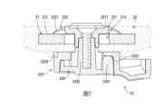
固定單元23具有一卡合件231、一彈性件232、一旋鈕233、及一抵靠件234。卡合件231能沿厚度方向移動,其具有一卡合部2311。卡合部2311選擇性地位於限位槽213,具體而言,當固定單元23在鎖定狀態時,卡合件231朝向限位槽213的方向移動,使得卡合部2311位於限位槽213內;而當固定單元23在解鎖狀態時,卡合件231朝向遠離限位槽213的方向移動,使得卡合部2311位於限位槽213外。The
當卡合部2311位於限位槽213時,其卡合於二槽壁面214,藉此固定滑塊22與基座21之間的相對位置。具體而言,卡合件231以卡合部2311選擇性地穿設於限位槽213,且當固定單元23在鎖定狀態時,卡合部2311位於限位槽213的其中一限位部2131中;由於卡合部2311的寬度小於或等於第一寬度W1,且大於第二寬度W2,故卡合部2311受到連接部2132的阻擋,進而使滑塊22無法沿長度方向移動。When the
彈性件232連接於卡合件231且位於限位槽213外,藉此卡合件231能沿厚度方向移動;在本實施例中,彈性件232連接於卡合件231的其中一端且與卡合件231一體成形,並具有兩個抵靠於底面212的翼部2321,藉此將卡合件231往底面212方向拉動,但不以此為限,其他實施例中,彈性件232可不與卡合件231一體成形。The
旋鈕233可轉動地套設於抵靠件234且抵靠於滑塊22;旋鈕233具有一斜面2331及一凹槽2332,斜面2331位於旋鈕233遠離滑塊22的一面,並沿旋鈕233的轉動方向傾斜。凹槽2332凹陷形成於旋鈕233的外周面,且沿周向延伸;具體而言,凹槽2332為一沿旋鈕233之外周面延伸的弧形長槽,且具有相對兩端,而滑塊22如圖2所示可進一步具有一凸出部221,其位於凹槽2332內;當固定單元23在鎖定狀態或解鎖狀態時,凸出部221係分別位於凹槽2332的相對兩端,藉此限制旋鈕233可轉動的角度範圍。The
抵靠件234連接於卡合件231相對於彈性件232的另一端,抵靠件234能沿厚度方向移動,本實施例中,抵靠件234包含一抵靠部2341及一桿部2342,桿部2342可移動地穿設於限位槽213並連接於卡合件231,且桿部2342的寬度小於限位槽213的第二寬度W2,藉此桿部2342能穿過限位槽213的連接部2132在各限位部2131之間移動;抵靠部2341相對可滑動地抵靠於斜面2331,藉此當旋鈕233旋轉時,斜面2331能推動抵靠件234並帶動卡合件231沿厚度方向移動。The
接著請參考圖5,當固定單元23在解鎖狀態時,卡合部2311位於限位槽213外,此時滑塊22可以相對於基座21沿長度方向自由移動;當旋鈕233轉動使斜面2331跟著轉動,進而推動抵靠件234,使抵靠件234沿厚度方向移動,並帶動卡合件231移入限位槽213,最後形成如圖6所示的鎖定狀態,使滑塊22無法相對於基座21移動而固定彼此之間的相對位置。Next, please refer to FIG. 5 . When the fixing
彈性件232的兩翼部2321抵靠於基座21的底面212,且傾向於往遠離底面212的方向撐起。當固定單元23從解鎖狀態變成鎖定狀態的過程中,彈性件232產生形變並累積位能;反之,當旋鈕233旋轉而使固定單元23從鎖定狀態往解鎖狀態變化的過程中,彈性件232逐漸往遠離底面212的方向撐起,並拉動卡合件231逐漸脫離限位槽213,最後恢復成如圖5所示的解鎖狀態。The two
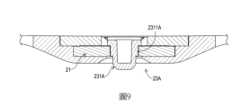
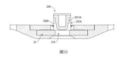
接著請參考圖7至圖10,本創作的可調整護具的第二實施例,其技術特徵大致與第一實施例相同,而主要的不同之處在於調整組件20A的固定單元23A。本創作之可調整護具的第二實施例中,固定單元23A包含一卡合件231A及一彈性件232A,彈性件232A為一長形件且具有相對兩端部,其中一端部連接於卡合件231A,而另一端部連接於滑塊22A;本實施例中的彈性件232A能彎折,藉此連接於卡合件231A的端部能相對於另一端部沿基座21的厚度方向移動。此外,本實施例中的彈性件232A可與滑塊22A為一體成形,但並不以此為限。Next, please refer to Figures 7 to 10, the second embodiment of the adjustable protective gear of the present invention, its technical features are roughly the same as the first embodiment, and the main difference lies in the fixing
具體而言,本實施例中的固定單元23A為按鈕的形式。如圖9中所示,當固定單元23A在鎖定狀態時,卡合部2311A位於限位槽213內;而當卡合件231A受厚度方向的施力移動,使卡合部2311A離開限位槽213,固定單元23A即形成如圖10中所示的解鎖狀態,而彈性件232A也受力變形。當卡合件231A不再受力,則彈性件232A恢復原形,而使卡合部2311A移回限位槽213之中,使固定單元23A恢復原本的鎖定狀態。Specifically, the fixing
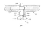
接著請參考圖11至圖14,本創作的可調整護具的第三實施例,其技術特徵大致與第一實施例相同,而主要的不同之處在於調整組件20B的滑塊22B與固定單元23B;此外,本實施例中滑塊22B與板件10為一體成形,但不以此為限。固定單元23B包含一卡合件231B及一彈性件232B,且滑塊22B進一步具有一第一抵靠面222B。第一抵靠面222B位於限位槽213外,且沿基座21的厚度方向朝向限位槽213。Next, please refer to Figures 11 to 14, the third embodiment of the adjustable protective gear of the present invention has substantially the same technical features as the first embodiment, and the main difference lies in the
卡合件231B進一步具有一第二抵靠面2312B,其沿基座21的厚度方向朝向第一抵靠面222B。具體而言,本實施例中的卡合件231B具有一卡合部2311B、一延伸部2313B、及一握把部2314B,第二抵靠面2312B為卡合部2311B朝向第一抵靠面222B之一面,延伸部2313B連接於卡合部2311B及握把部2314B之間,且延伸部2313B從第二抵靠面2312B往滑塊22B的第一抵靠面222B方向延伸並貫穿第一抵靠面222B,握把部2314B位於滑塊22B之外,並選擇性地抵靠於滑塊22B相對於第一抵靠面222B的另一面。The engaging
彈性件232B為一壓縮彈簧,其套設於卡合件231B的延伸部2313B,且彈性件232B的相對兩端分別抵靠於第一抵靠面222B及第二抵靠面2312B。The
具體而言,本實施例中的固定單元23B為插銷的形式。如圖13中所示,固定單元23B在鎖定狀態時,卡合部2311B位於限位槽213中,使用者可以藉由握持握把部2314B拉動卡合件231B,使第二抵靠面2312B往第一抵靠面222B的方向移動,同時壓縮彈性件232B;最後固定單元23B形成圖14所示的解鎖狀態,此時卡合部2311B位於限位槽213外。當使用者鬆手後,彈性件232B即會伸長並推動卡合件231B回復至如圖13中所示的位置,使固定單元23B回復至鎖定狀態,但並不以此為限;例如可改變握把部2314B與延伸部2313B的連接形式,使固定單元23B形成一種按壓形式的插銷。Specifically, the fixing
本創作藉由固定單元23的卡合件231卡合於限位槽213中的不同位置,可調整滑塊22與基座21之間的相對位置,進一步調整本創作的可調整護具的兩板件10之間的距離,而達成調整可調整護具整體長度的功效;藉此能配合使用者的身形或傷害狀況,調整本創作的可調整護具所支撐的身體位置,而不必耗費成本購置不同尺寸的護具,或者忍受不恰當尺寸的護具所造成的不適。By engaging the engaging
10:板件 11:穿孔 20,20A,20B:調整組件 21:基座 211:頂面 212:底面 213:限位槽 2131:限位部 2132:連接部 214:槽壁面 22,22A,22B:滑塊 221:凸出部 222B:第一抵靠面 23,23A,23B:固定單元 231,231A,231B:卡合件 2311,2311A,2311B:卡合部 2312B:第二抵靠面 2313B:延伸部 2314B:握把部 232,232A,232B:彈性件 2321:翼部 233:旋鈕 2331:斜面 2332:凹槽 234:抵靠件 2341:抵靠部 2342:桿部 W1:第一寬度 W2:第二寬度10: Plate11:
圖1為本創作第一實施例的外觀示意圖。 圖2為本創作第一實施例的調整長度後的外觀示意圖。 圖3為本創作第一實施例的部分分解示意圖。 圖4為本創作第一實施例另一視角的部分分解示意圖。 圖5為本創作第一實施例的剖視示意圖,其顯示了解鎖狀態的固定單元。 圖6為本創作第一實施例的剖視示意圖,其顯示了鎖定狀態的固定單元。 圖7為本創作第二實施例的外觀示意圖。 圖8為本創作第二實施例之調整組件的立體分解示意圖。 圖9為本創作第二實施例的剖視示意圖,其顯示了鎖定狀態的固定單元。 圖10為本創作第二實施例的剖視示意圖,其顯示了解鎖狀態的固定單元。 圖11為本創作第三實施例的外觀示意圖。 圖12為本創作第三實施例的部分分解示意圖。 圖13為本創作第三實施例的剖視示意圖,其顯示了鎖定狀態的固定單元。 圖14為本創作第三實施例的剖視示意圖,其顯示了解鎖狀態的固定單元。Figure 1 is a schematic diagram of the appearance of the first embodiment of the present invention.Figure 2 is a schematic diagram of the appearance of the first embodiment of the present invention after adjusting the length.Figure 3 is a partially exploded schematic diagram of the first embodiment of the present invention.Figure 4 is a partially exploded schematic diagram of another viewing angle of the first embodiment of the present invention.Figure 5 is a cross-sectional schematic diagram of the first embodiment of the present invention, which shows the fixed unit in the unlocked state.Figure 6 is a cross-sectional schematic diagram of the first embodiment of the present invention, which shows the fixed unit in the locked state.Figure 7 is a schematic diagram of the appearance of the second embodiment of the present invention.Figure 8 is a three-dimensional exploded schematic diagram of the adjustment assembly of the second embodiment of the present invention.Figure 9 is a cross-sectional schematic diagram of the second embodiment of the present invention, which shows the fixed unit in the locked state.Figure 10 is a cross-sectional schematic diagram of the second embodiment of the present invention, which shows the fixed unit in the unlocked state.FIG. 11 is a schematic diagram of the appearance of the third embodiment of the present invention.FIG. 12 is a partially exploded schematic diagram of the third embodiment of the present invention.FIG. 13 is a cross-sectional schematic diagram of the third embodiment of the present invention, which shows the fixed unit in a locked state.FIG. 14 is a cross-sectional schematic diagram of the third embodiment of the present invention, which shows the fixed unit in an unlocked state.
10:板件10: Panels
11:穿孔11:Piercing
20:調整組件20: Adjustment components
Claims (10)
Translated fromChinesePriority Applications (1)
| Application Number | Priority Date | Filing Date | Title |
|---|---|---|---|
| TW112132575ATWI843648B (en) | 2023-08-29 | 2023-08-29 | Adjustable protective gear and adjustment assembly thereof |
Applications Claiming Priority (1)
| Application Number | Priority Date | Filing Date | Title |
|---|---|---|---|
| TW112132575ATWI843648B (en) | 2023-08-29 | 2023-08-29 | Adjustable protective gear and adjustment assembly thereof |
Publications (2)
| Publication Number | Publication Date |
|---|---|
| TWI843648Btrue TWI843648B (en) | 2024-05-21 |
| TW202510822A TW202510822A (en) | 2025-03-16 |
Family
ID=92077236
Family Applications (1)
| Application Number | Title | Priority Date | Filing Date |
|---|---|---|---|
| TW112132575ATWI843648B (en) | 2023-08-29 | 2023-08-29 | Adjustable protective gear and adjustment assembly thereof |
Country Status (1)
| Country | Link |
|---|---|
| TW (1) | TWI843648B (en) |
Citations (3)
| Publication number | Priority date | Publication date | Assignee | Title |
|---|---|---|---|---|
| CN112006828A (en)* | 2020-09-23 | 2020-12-01 | 四川大学华西医院 | Energy-concerving and environment-protective orthopedics protective equipment |
| CN113855365A (en)* | 2021-09-13 | 2021-12-31 | 南京市儿童医院 | Ankle joint ligament protection utensil |
| TWM649068U (en)* | 2023-08-29 | 2023-12-01 | 億萊富國際股份有限公司 | Adjustable protective gear and adjustment components thereof |
- 2023
- 2023-08-29TWTW112132575Apatent/TWI843648B/enactive
Patent Citations (3)
| Publication number | Priority date | Publication date | Assignee | Title |
|---|---|---|---|---|
| CN112006828A (en)* | 2020-09-23 | 2020-12-01 | 四川大学华西医院 | Energy-concerving and environment-protective orthopedics protective equipment |
| CN113855365A (en)* | 2021-09-13 | 2021-12-31 | 南京市儿童医院 | Ankle joint ligament protection utensil |
| TWM649068U (en)* | 2023-08-29 | 2023-12-01 | 億萊富國際股份有限公司 | Adjustable protective gear and adjustment components thereof |
Also Published As
| Publication number | Publication date |
|---|---|
| TW202510822A (en) | 2025-03-16 |
Similar Documents
| Publication | Publication Date | Title |
|---|---|---|
| KR102246052B1 (en) | Rehabilitation exercise apparatus for upper limb and lower limb | |
| KR102246049B1 (en) | Rehabilitation exercise apparatus for upper limb and lower limb | |
| KR102246051B1 (en) | Rehabilitation exercise apparatus for upper limb and lower limb | |
| KR102246050B1 (en) | Rehabilitation exercise apparatus for upper limb and lower limb | |
| US8517965B2 (en) | Orthopedic brace having length-adjustable supports | |
| JP6776218B2 (en) | Boots stirrup | |
| US20140364782A1 (en) | Knee brace with tool less length adjuster | |
| US9993362B2 (en) | Adjustable knee brace | |
| KR101892573B1 (en) | Wrist guard | |
| AU2002232583A1 (en) | Orthopedic brace having length-adjustable supports | |
| US20050035644A1 (en) | Portable massage chair | |
| US20160175192A1 (en) | Adjustable acupoint and organ pressing device | |
| JP2001520080A (en) | Joint orthosis hinge | |
| US20200179153A1 (en) | Adjustable back support apparatus | |
| US20160166462A1 (en) | Personal massage apparatus | |
| TWI843648B (en) | Adjustable protective gear and adjustment assembly thereof | |
| TWM649068U (en) | Adjustable protective gear and adjustment components thereof | |
| CA2801377A1 (en) | Humerus-stabilized shoulder stretch device | |
| CN221205824U (en) | Adjustable protective equipment and adjusting assembly thereof | |
| KR102085527B1 (en) | Length Adjusting Mechanism for a Walking Exoskeleton and Walking Exoskeleton comprising the same | |
| CN119523712A (en) | Adjustable protective gear and adjustment components thereof | |
| KR102117876B1 (en) | Assistance tool for leg capable of controlling tilting angle | |
| CN112245218B (en) | A leg support mechanism | |
| CN106691658A (en) | Knee-joint fixing supporting tool | |
| US20250107914A1 (en) | Adjustable body brace and adjusting assembly thereof |