TWI843196B - Rotary transfer vertical coating equipment and double-sided multi-layer coating method - Google Patents
Rotary transfer vertical coating equipment and double-sided multi-layer coating methodDownload PDFInfo
- Publication number
- TWI843196B TWI843196BTW111133992ATW111133992ATWI843196BTW I843196 BTWI843196 BTW I843196BTW 111133992 ATW111133992 ATW 111133992ATW 111133992 ATW111133992 ATW 111133992ATW I843196 BTWI843196 BTW I843196B
- Authority
- TW
- Taiwan
- Prior art keywords
- chamber
- rotary
- vacuum process
- axis
- opening
- Prior art date
Links
- 238000000576coating methodMethods0.000titleclaimsabstractdescription120
- 239000011248coating agentSubstances0.000titleclaimsabstractdescription112
- 238000012546transferMethods0.000titleclaimsabstractdescription34
- 238000000034methodMethods0.000claimsabstractdescription148
- 230000008569processEffects0.000claimsabstractdescription137
- 238000007872degassingMethods0.000claimsdescription31
- 238000004140cleaningMethods0.000claimsdescription28
- 238000007747platingMethods0.000claimsdescription21
- 239000007888film coatingSubstances0.000claimsdescription13
- 238000009501film coatingMethods0.000claimsdescription13
- 230000032258transportEffects0.000claimsdescription13
- 239000010949copperSubstances0.000claimsdescription11
- 238000012545processingMethods0.000claimsdescription11
- 239000010936titaniumSubstances0.000claimsdescription8
- RYGMFSIKBFXOCR-UHFFFAOYSA-NCopperChemical compound[Cu]RYGMFSIKBFXOCR-UHFFFAOYSA-N0.000claimsdescription7
- 229910052802copperInorganic materials0.000claimsdescription7
- RTAQQCXQSZGOHL-UHFFFAOYSA-NTitaniumChemical compound[Ti]RTAQQCXQSZGOHL-UHFFFAOYSA-N0.000claimsdescription5
- 238000004544sputter depositionMethods0.000claimsdescription5
- 229910052719titaniumInorganic materials0.000claimsdescription5
- 230000000694effectsEffects0.000abstractdescription8
- 239000010410layerSubstances0.000description11
- 238000011068loading methodMethods0.000description10
- 238000010992refluxMethods0.000description9
- 239000000969carrierSubstances0.000description8
- 238000012423maintenanceMethods0.000description7
- 238000004519manufacturing processMethods0.000description7
- 239000000463materialSubstances0.000description7
- 238000001771vacuum depositionMethods0.000description7
- 238000005265energy consumptionMethods0.000description6
- 239000000758substrateSubstances0.000description6
- 238000010407vacuum cleaningMethods0.000description6
- XLYOFNOQVPJJNP-UHFFFAOYSA-NwaterSubstancesOXLYOFNOQVPJJNP-UHFFFAOYSA-N0.000description6
- 230000008901benefitEffects0.000description5
- 230000009467reductionEffects0.000description5
- 238000009849vacuum degassingMethods0.000description5
- 239000010931goldSubstances0.000description4
- 238000010586diagramMethods0.000description3
- OKTJSMMVPCPJKN-UHFFFAOYSA-NCarbonChemical compound[C]OKTJSMMVPCPJKN-UHFFFAOYSA-N0.000description2
- BQCADISMDOOEFD-UHFFFAOYSA-NSilverChemical compound[Ag]BQCADISMDOOEFD-UHFFFAOYSA-N0.000description2
- 229910000756V alloyInorganic materials0.000description2
- 229910052799carbonInorganic materials0.000description2
- 239000011247coating layerSubstances0.000description2
- 238000010276constructionMethods0.000description2
- 238000001816coolingMethods0.000description2
- 230000002542deteriorative effectEffects0.000description2
- 239000011521glassSubstances0.000description2
- PCHJSUWPFVWCPO-UHFFFAOYSA-NgoldChemical compound[Au]PCHJSUWPFVWCPO-UHFFFAOYSA-N0.000description2
- 229910052737goldInorganic materials0.000description2
- 238000009434installationMethods0.000description2
- 238000001465metallisationMethods0.000description2
- HBVFXTAPOLSOPB-UHFFFAOYSA-Nnickel vanadiumChemical compound[V].[Ni]HBVFXTAPOLSOPB-UHFFFAOYSA-N0.000description2
- 229910052709silverInorganic materials0.000description2
- 239000004332silverSubstances0.000description2
- 239000013077target materialSubstances0.000description2
- 229910000881Cu alloyInorganic materials0.000description1
- 230000005540biological transmissionEffects0.000description1
- VNNRSPGTAMTISX-UHFFFAOYSA-Nchromium nickelChemical compound[Cr].[Ni]VNNRSPGTAMTISX-UHFFFAOYSA-N0.000description1
- 239000000112cooling gasSubstances0.000description1
- 230000003247decreasing effectEffects0.000description1
- 238000007599dischargingMethods0.000description1
- 239000007789gasSubstances0.000description1
- 230000005484gravityEffects0.000description1
- 238000002955isolationMethods0.000description1
- 230000007774longtermEffects0.000description1
- 229910052751metalInorganic materials0.000description1
- 239000002184metalSubstances0.000description1
- 238000002156mixingMethods0.000description1
- 238000012986modificationMethods0.000description1
- 230000004048modificationEffects0.000description1
- 229910001120nichromeInorganic materials0.000description1
- 229910052759nickelInorganic materials0.000description1
- 229910052755nonmetalInorganic materials0.000description1
- 239000010935stainless steelSubstances0.000description1
- 229910001220stainless steelInorganic materials0.000description1
- 238000010301surface-oxidation reactionMethods0.000description1
- 229910052715tantalumInorganic materials0.000description1
- 238000011282treatmentMethods0.000description1
Images


Landscapes
- Physical Vapour Deposition (AREA)
Abstract
Translated fromChineseDescription
Translated fromChinese本發明是有關於一種鍍膜設備,特別是指一種旋轉移載式立式鍍膜設備及雙面多層膜的鍍膜方法。The present invention relates to a coating device, in particular to a rotary transfer vertical coating device and a double-sided multi-layer coating method.
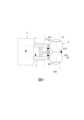
參閱圖1、圖2,該鍍膜設備適用於對一待鍍物(圖未示)進行兩種不同鍍膜材質的雙面鍍膜,並包括相反設置的一入料腔11及一出料腔12、一真空除氣腔13、二真空清潔腔14、四真空鍍膜腔15、一回流通道16、複數在設備中循環移動的承載裝置17、四個分別設置於該等真空鍍膜腔15用來供鍍膜使用的靶材18,及二設置於該等真空清潔腔14且分別可對該待鍍物其中一面進行清潔的清潔模組19。該真空除氣腔13、該等真空清潔腔14、該等真空鍍膜腔15依序設置於該入料腔11與該出料腔12間,該回流通道16連接於該入料腔11及該出料腔12間並位於上方。Referring to Figures 1 and 2, the coating equipment is suitable for double-sided coating of two different coating materials on an object to be coated (not shown), and includes an
運作時,每一承載裝置17移動到該入料腔11後,將該待鍍物設置於該承載裝置17上,該承載裝置17再依序經過該真空除氣腔13、該等真空清潔腔14,及於不同的該等真空鍍膜腔15以該等靶材18對該待鍍物的相反兩面進行鍍膜,最後,該承載裝置17移動到該出料腔12後,卸下該待鍍物以完成雙面鍍膜的製程,該承載裝置17再經由該回流通道16回到該入料腔11,以便進行下一次鍍膜製程。During operation, after each
然而,由於該等真空清潔腔14只能朝單一方向進行處理,因此必須設置兩個真空清潔腔14,並朝相反的兩個方向對該待鍍物的相反兩面進行清潔。當要進行兩種不同鍍膜材質的雙面鍍膜時,由於鍍膜的方向決定了該等靶材18的設置位置,因而需要配置四個真空鍍膜腔15而形成一狹長條形的格局,進而導致設備的佔用面積較大,及產生狹長型設備的周邊剩餘空間難以利用的問題。而真空腔的數量增加,也導致需消耗更多的能源以維持真空腔內的真空度。However, since the
此外,由於該回流通道16的長度較長,該等承載裝置17經由該回流通道16回到該入料腔11所需的時間較長,因此需額外準備更多的承載裝置17以利於不間斷的生產,導致其建構成本及後期維護成本較高。In addition, due to the long length of the
因此,本發明之目的,即在提供一種可減少佔地面積、提高生產靈活度與生產效率、降低維護成本,及降低能源消耗的旋轉移載式立式鍍膜設備及雙面多層膜的鍍膜方法。Therefore, the purpose of the present invention is to provide a rotary transfer vertical coating equipment and a double-sided multi-layer coating method that can reduce the floor space occupied, improve production flexibility and production efficiency, reduce maintenance costs, and reduce energy consumption.
於是,本發明旋轉移載式立式鍍膜設備,適用以對至少一待鍍物進行鍍膜,該旋轉移載式立式鍍膜設備包含複數真空製程腔,及一旋轉裝置。Therefore, the rotary transfer type vertical coating equipment of the present invention is suitable for coating at least one object to be coated. The rotary transfer type vertical coating equipment includes a plurality of vacuum process chambers and a rotating device.
該等真空製程腔分別設置於該第一軸線及該第二軸線上,且能容置及沿該第一軸線及該第二軸線輸送該待鍍物,每一真空製程腔進行單向加工。The vacuum process chambers are respectively arranged on the first axis and the second axis, and can accommodate and transport the object to be plated along the first axis and the second axis. Each vacuum process chamber performs unidirectional processing.
該旋轉裝置,包括一第一旋轉腔及一第二旋轉腔。The rotating device includes a first rotating chamber and a second rotating chamber.
該第一旋轉腔設置於該第一軸線上,並包括一位於該第一軸線且連接其中一真空製程腔的後開口、一位於該第一軸線與該第二軸線之間的側開口,及一能容置且可驅動該待鍍物旋轉並具有一頭端及一尾端的旋轉模組,該旋轉模組能以該頭端朝向該後開口、以該尾端朝向該後開口,及以該頭端及該尾端的其中之一朝向該側開口,該待鍍物能自該旋轉模組的頭端或尾端移入及移出,並可往復進入該第一旋轉腔及與該第一旋轉腔連接的該真空製程腔,且可受該旋轉模組翻轉180度後返回同一個該真空製程腔,以使該待鍍物的相反兩面可受該真空製程腔加工。The first rotary chamber is arranged on the first axis and includes a rear opening on the first axis and connected to one of the vacuum process chambers, a side opening between the first axis and the second axis, and a rotary module that can accommodate and drive the object to be plated to rotate and has a head end and a tail end. The rotary module can face the rear opening with the head end, face the rear opening with the tail end, and face the side opening with one of the head end and the tail end. The object to be plated can move in and out from the head end or the tail end of the rotary module, and can reciprocate into the first rotary chamber and the vacuum process chamber connected to the first rotary chamber, and can be turned 180 degrees by the rotary module and return to the same vacuum process chamber, so that the opposite sides of the object to be plated can be processed by the vacuum process chamber.
該第二旋轉腔設置於該第二軸線上,並包括一位於該第二軸線且連接其中另一真空製程腔的後開口、一位於該第一軸線與該第二軸線之間且對應該第一旋轉腔的側開口,及一能容置且可驅動該待鍍物旋轉並具有一頭端及一尾端的旋轉模組,該旋轉模組能以該頭端朝向該後開口、以該尾端朝向該後開口,及以該頭端及該尾端的其中之一朝向該側開口,該待鍍物能自該旋轉模組的頭端或尾端移入及移出,並可往復進入該第二旋轉腔及與該第二旋轉腔連接的該真空製程腔,且可受該旋轉模組翻轉180度後返回同一個該真空製程腔,以使該待鍍物的相反兩面可受該真空製程腔加工。The second rotary chamber is arranged on the second axis and includes a rear opening on the second axis and connected to another vacuum process chamber, a side opening between the first axis and the second axis and corresponding to the first rotary chamber, and a rotary module that can accommodate and drive the object to be plated to rotate and has a head end and a tail end. The rotary module can face the rear opening with the head end, the rear opening with the tail end, and the side opening with one of the head end and the tail end. The object to be plated can move in and out from the head end or the tail end of the rotary module, and can reciprocate into the second rotary chamber and the vacuum process chamber connected to the second rotary chamber, and can be turned 180 degrees by the rotary module and return to the same vacuum process chamber, so that the opposite sides of the object to be plated can be processed by the vacuum process chamber.
於是,本發明雙面多層膜的鍍膜方法,適用於利用複數真空製程腔對一直立設置的待鍍物進行雙面鍍膜,該雙面多層膜的鍍膜方法包含下列步驟:(A)輸送該待鍍物至其中一真空製程腔,該其中一真空製程腔連接一旋轉腔並與該旋轉腔沿一軸線排列,該旋轉腔包括一後開口及一側開口,該後開口連接於該其中一真空製程腔,且該後開口與該側開口不同時位於該軸線上,(B)於該其中一真空製程腔內對該待鍍物的其中一個面進行除氣、清潔及濺鍍鍍膜的其中一種加工,(C)將該待鍍物自該其中一真空製程腔輸送至該旋轉腔,並於該旋轉腔將該待鍍物旋轉180度後,將該待鍍物自該旋轉腔輸送回該其中一真空製程腔,(D)於該其中一真空製程腔內對該待鍍物的其中另一面進行相同於步驟(B)的加工,(E)將該待鍍物自該其中一真空製程腔輸送至該旋轉腔,且於該旋轉腔內旋轉該待鍍物並朝向該側開口後,將該待鍍物自該側開口移出該旋轉腔,及(F)將該待鍍物移入其中另一真空製程腔。Therefore, the double-sided multi-layer film coating method of the present invention is suitable for double-sided coating of a vertically arranged object to be coated using a plurality of vacuum process chambers. The double-sided multi-layer film coating method includes the following steps: (A) transporting the object to be coated to one of the vacuum process chambers, wherein the one of the vacuum process chambers is connected to a rotating chamber and is arranged along an axis with the rotating chamber, wherein the rotating chamber includes a rear opening and a side opening, wherein the rear opening is connected to the one of the vacuum process chambers, and the rear opening and the side opening are not located on the axis at the same time; (B) degassing, cleaning and sputter coating are performed on one of the surfaces of the object to be coated in the one of the vacuum process chambers. (C) transporting the object to be plated from one of the vacuum process chambers to the rotary chamber, and after rotating the object to be plated 180 degrees in the rotary chamber, transporting the object to be plated from the rotary chamber back to one of the vacuum process chambers, (D) performing the same processing as step (B) on the other side of the object to be plated in one of the vacuum process chambers, (E) transporting the object to be plated from one of the vacuum process chambers to the rotary chamber, and after rotating the object to be plated in the rotary chamber and facing the side opening, moving the object to be plated out of the rotary chamber through the side opening, and (F) moving the object to be plated into another of the vacuum process chambers.
於是,本發明雙面多層膜的鍍膜方法,適用於利用複數真空製程腔對一直立設置的待鍍物進行雙面鍍膜,該雙面多層膜的鍍膜方法包含下列步驟:(A)輸送該待鍍物進入至該旋轉腔,該旋轉腔與其中一真空製程腔沿一軸線排列,該旋轉腔包括一後開口及一側開口,該後開口連接於該其中一真空製程腔,該側開口不位於該軸線上,該待鍍物自該側開口進入,(B)該旋轉腔旋轉該待鍍物,並使其自該後開口輸送至該其中一真空製程腔,並於該其中一真空製程腔內對該待鍍物的其中一個面進行除氣、清潔及濺鍍鍍膜的其中一種加工,(C)將該待鍍物自該其中一真空製程腔輸送至該旋轉腔,並於該旋轉腔將該待鍍物旋轉180度後,將該待鍍物自該旋轉腔輸送回該其中一真空製程腔,(D)於該其中一真空製程腔內對該待鍍物的其中另一面進行相同於步驟(B)的加工,(E)將該待鍍物移入其中另一真空製程腔。Therefore, the double-sided multi-layer film coating method of the present invention is suitable for double-sided coating of a vertically arranged object to be coated using a plurality of vacuum process chambers. The double-sided multi-layer film coating method includes the following steps: (A) transporting the object to be coated into the rotating chamber, the rotating chamber and one of the vacuum process chambers are arranged along an axis, the rotating chamber includes a rear opening and a side opening, the rear opening is connected to one of the vacuum process chambers, the side opening is not located on the axis, and the object to be coated enters from the side opening; (B) the rotating chamber rotates the object to be coated and transports it from the rear opening. To one of the vacuum process chambers, and perform one of the processes of degassing, cleaning and sputtering on one of the surfaces of the object to be plated in the vacuum process chamber, (C) transport the object to be plated from the vacuum process chamber to the rotating chamber, and after rotating the object to be plated 180 degrees in the rotating chamber, transport the object to be plated from the rotating chamber back to the vacuum process chamber, (D) perform the same process as step (B) on the other surface of the object to be plated in the vacuum process chamber, (E) move the object to be plated into another vacuum process chamber.
本發明之功效在於:藉由該等真空製程腔、該第一旋轉腔及該第二旋轉腔的設置,使得可用單一個僅能朝單方向進行加工的真空製程腔對該待鍍物的相反兩面進行加工,能提高生產靈活度與生產效率,亦能減少該真空製程腔的數量,進一步降低維持真空所需的能源消耗及維護成本,此外,藉由沿該第一軸線及該第二軸線排列,減少整體在該第一軸線上的長度,達到減少佔地面積且易於利用空間的功效。The effect of the present invention is that: by setting the vacuum process chambers, the first rotary chamber and the second rotary chamber, a single vacuum process chamber that can only process in one direction can be used to process the opposite sides of the object to be plated, which can improve production flexibility and production efficiency, and can also reduce the number of vacuum process chambers, further reducing the energy consumption and maintenance costs required to maintain vacuum. In addition, by arranging along the first axis and the second axis, the overall length on the first axis is reduced, thereby achieving the effect of reducing the floor space occupied and facilitating the use of space.
2:承載裝置2: Carrier device
21:載具21: Vehicles
3:真空製程腔3: Vacuum process chamber
31:裝載腔體31: Loading chamber
32:除氣腔體32: Degassing chamber
33:清潔腔體33: Clean the cavity
34:第一鍍膜腔體34: First coating chamber
35:第二鍍膜腔體35: Second coating chamber
36:緩衝腔體36: Buffer cavity
37:卸載腔體37: Unloading chamber
4:旋轉裝置4: Rotating device
41:第一旋轉腔41: First rotary chamber
411:後開口411: Rear opening
412:前開口412: Front opening
413:側開口413: Side opening
414:旋轉模組414: Rotation module
415:頭端415: Headend
416:尾端416: Tail end
417:外開口417: External opening
42:第二旋轉腔42: Second rotary chamber
421:後開口421: Rear opening
422:前開口422: Front opening
423:側開口423: Side opening
424:旋轉模組424: Rotation module
425:頭端425: Headend
426:尾端426: Tail end
427:外開口427: External opening
43:中繼腔43: Relay cavity
5:回流裝置5: Reflux device
81~86:步驟81~86: Steps
91~95:步驟91~95: Steps
9:待鍍物9: Objects to be plated
L1:第一軸線L1: First axis
L2:第二軸線L2: Second axis
L3:第三軸線L3: The third axis
L4:第四軸線L4: The fourth axis
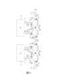
本發明之其他的特徵及功效,將於參照圖式的實施方式中清楚地呈現,其中:圖1是一側視示意圖,說明一習知的鍍膜設備;圖2是該習知的鍍膜設備的一俯視示意圖;圖3是一立體圖,說明本發明旋轉移載式立式鍍膜設備的一個實施例的一承載裝置及一待鍍物;圖4是該實施例的一俯視圖;圖5是該實施例的另一俯視圖,說明二旋轉模組各自的頭端分別朝向二旋轉裝置的前開口;圖6是該實施例的另一俯視圖,說明該等頭端分別朝向該等旋轉裝置各自的側開口;圖7是一俯視圖,說明該實施例的該旋轉裝置的另一種配置;圖8是一俯視圖,說明本發明旋轉移載式立式鍍膜設備的一個第一變化例;圖9是一俯視圖,說明本發明旋轉移載式立式鍍膜設備的一個第二變化例;圖10是一俯視圖,說明本發明旋轉移載式立式鍍膜設備的一個第三變化例;圖11是一俯視圖,說明本發明旋轉移載式立式鍍膜設備的一個第四變化例;圖12是一俯視圖,說明本發明旋轉移載式立式鍍膜設備的一個第五變化例;圖13是一俯視圖,說明本發明旋轉移載式立式鍍膜設備的一個第六變化例;圖14是一流程圖,說明本發明雙面多層膜的鍍膜方法的一第一實施例;及圖15是一流程圖,說明本發明雙面多層膜的鍍膜方法的一第二實施例。Other features and effects of the present invention will be clearly presented in the implementation method with reference to the drawings, in which: FIG. 1 is a side view schematic diagram illustrating a known coating device; FIG. 2 is a top view schematic diagram of the known coating device; FIG. 3 is a three-dimensional diagram illustrating a carrier device and an object to be coated of an embodiment of the rotary transfer type vertical coating device of the present invention; FIG. 4 is a top view of the embodiment; FIG. 5 is another top view of the embodiment, illustrating that the head ends of the two rotating modules are respectively facing the front openings of the two rotating devices; FIG. 6 is another top view of the embodiment, illustrating that the head ends are respectively facing the side openings of the rotating devices; FIG. 7 is a top view illustrating another configuration of the rotating device of the embodiment; FIG. 8 is a top view illustrating the rotary transfer type of the present invention. FIG9 is a top view illustrating a second variation of the rotary transfer type vertical coating device of the present invention; FIG10 is a top view illustrating a third variation of the rotary transfer type vertical coating device of the present invention; FIG11 is a top view illustrating a fourth variation of the rotary transfer type vertical coating device of the present invention; FIG12 is a top view , illustrating a fifth variation of the rotary transfer vertical coating device of the present invention; FIG. 13 is a top view illustrating a sixth variation of the rotary transfer vertical coating device of the present invention; FIG. 14 is a flow chart illustrating a first embodiment of the double-sided multi-layer coating method of the present invention; and FIG. 15 is a flow chart illustrating a second embodiment of the double-sided multi-layer coating method of the present invention.
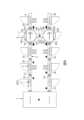
參閱圖3、圖4,本發明旋轉移載式立式鍍膜設備的實施例適用於複數直立設置的待鍍物9,該等待鍍物9可以是機殼、面板級扇出型封裝(FOPLP)、晶圓級扇出型封裝(FOWLP)、埋入式基板、無核心基板、玻璃基板、封裝基板、PCB基板、晶圓或晶圓級封裝等金屬及非金屬物。定義一第一軸線L1及一第二軸線L2。該旋轉移載式立式鍍膜設備包含一承載裝置2、複數真空製程腔3、一旋轉裝置4,及一回流裝置5。Referring to Figures 3 and 4, the embodiment of the rotary transfer type vertical coating equipment of the present invention is applicable to a plurality of vertically arranged objects to be coated 9, which can be metal and non-metal objects such as a housing, a panel-level fan-out package (FOPLP), a wafer-level fan-out package (FOWLP), an embedded substrate, a coreless substrate, a glass substrate, a package substrate, a PCB substrate, a wafer or a wafer-level package. A first axis L1 and a second axis L2 are defined. The rotary transfer type vertical coating equipment includes a
於本實施例中,該第一軸線L1與該第二軸線L2是平行。惟於其他實施態樣中,也能因廠房的空間配置而略成一角度,並不以此為限。In this embodiment, the first axis L1 and the second axis L2 are parallel.However, in other embodiments, they can also be slightly angled due to the spatial configuration of the factory, and are not limited to this.
該承載裝置2包括複數直立設置且適用以承載該等待鍍物9的載具21,於本實施例中,每一載具21呈矩形框狀,於其他實施態樣中,若該待鍍物9的結構強度較高(例如自身帶框的玻璃基板時),亦能不設置該承載裝置2。應說明的是,固定於每一載具21的待鍍物9數量也可以是數個,並不以此為限。The
為了利於後續的說明,以下將以一個載具21及一個待鍍物9為例,此時,該待鍍物9是固定於該載具21的中間部位,藉此保護該待鍍物9不於加工或運輸時受損,並給予該待鍍物9一定張力,使其抵抗因重力而產生之變形,藉此達到均勻的加工品質。該待鍍物9在該載具21的水平方向上開放以接受鍍膜製程中的各種處置。For the convenience of subsequent explanation, a
該等真空製程腔3分別設置於該第一軸線L1及該第二軸線L2上,且能容置及分別沿該第一軸線L1及該第二軸線L2輸送該載具21及該待鍍物9,每一真空製程腔3進行單向加工。The
於本實施例中,該等真空製程腔3的數量是8個,且分別是設置於該第一軸線L1上的一裝載腔體31、二除氣腔體32,及一清潔腔體33,及設置於該第二軸線L2上的一第一鍍膜腔體34、一第二鍍膜腔體35、一緩衝腔體36,及一卸載腔體37。該等真空製程腔3之間可以設置閥門(圖未示),藉此維持腔內真空度的穩定。In this embodiment, the number of the
該裝載腔體31用於進料。The
該等除氣腔體32彼此相連接且可對進入內部的該載具21及該待鍍物9進行真空除氣(Degas),去除因與外界空氣接觸而吸附於該載具21及該待鍍物9的水分子與氣體。藉由設置該等除氣腔體32能提高生產效率,例如將該載具21及該待鍍物9分別於其中一除氣腔體32內置放3分鐘並將其抽至一低真空度,並於其中另一除氣腔體32內置放3分鐘並將其抽至一高真空度,藉此共能累積6分鐘的除氣時間且分散建立真空度所需的時間,進一步達到更佳的製程效率。The degassing
除氣腔體32的數量不以二個為限。除了可增加除氣腔室32的數量以分散降低每一次停留所需的時間之外,於其他實施態樣中,為了進一步提高製程的良率,亦能於該裝載腔體31之前設置至少一烤箱(圖未示),由於該待鍍物9自其他製程工序移送至本發明的實施例時,可能因暴露於大氣的時間較長而吸附較多的水氣。藉由將該待鍍物9於該至少一烤箱內烘烤一時間,實務上約為烘烤30分鐘至1小時之間,能有效減少該待鍍物9於該等除氣腔體32內所需的除氣時間,進一步能減少該等除氣腔體32的數量或不裝設該除氣腔體32。此外,另於其他實施態樣中,亦能使該裝載腔室31具有真空除氣的功能,藉此能減少該等除氣腔體32的數量或不裝設該除氣腔體32。The number of
該清潔腔體33與該等除氣腔體32間隔設置,且用來對進入內部的該待鍍物9進行清潔。於本實施例中,是以電漿清洗(Plasma)的製程方法。The cleaning
該第一鍍膜腔體34及該第二鍍膜腔體35間隔設置,且用來對該待鍍物9進行鍍膜。該第一鍍膜腔體34與該第二鍍膜腔體35用來鍍膜的材質相異。於本實施例中,該第一鍍膜腔體34是用來對該待鍍物9進行鍍鈦(Ti),該第二鍍膜腔體35是用來對該待鍍物9的進行鍍銅(Cu),於其他實施態樣中,也可依需求選用其他鍍膜材料。The
此外,也可依鍍膜層數需求增減鍍膜腔體的數量,例如當需要鍍上較厚的銅層時,可以設置二個以上的第二鍍膜腔體35。In addition, the number of coating chambers can be increased or decreased according to the number of coating layers required. For example, when a thicker copper layer needs to be coated, more than two
能理解的是,該第一鍍膜腔體34除了鍍鈦以外,在一些實施態樣中,也可以鍍TiW、Cr、NiCr、Ni、Ta、CuN、Ti/TiN、Ta/TaN、SUS。而該第二鍍膜腔體35除了鍍銅以外,在一些實施態樣中,也可以鍍銅合金。此外,在不同的實施態樣中,該第一鍍膜腔體34與該第二鍍膜腔體35的鍍膜種類也能互換。鍍膜種類及層數並非本發明的一限制,使用者可依實際鍍膜需求來選用鍍膜材質及配置鍍膜腔體的數量。It is understood that, in addition to titanium plating, the
要特別再說明的是,在上述實施例中的該等真空製程腔3內都能設置高效率的冷卻模組,例如冷卻管路或在腔內通入冷卻氣體,以有效控制該待鍍物9的溫度,及減少該待鍍物9的變形,提升產品良率。It should be particularly noted that in the above-mentioned embodiments, a high-efficiency cooling module can be installed in the
該緩衝腔體36連接於該第二鍍膜腔體35且用來輸送及容置該承載裝置2。於本實施例中,由於該第一鍍膜腔體34及該第二鍍膜腔體35於製程時所需的本底真空度(Base pressure)較高(壓力值約介於10-5~10-8Torr,通常為10-6Torr,較佳的為10-7Torr),藉由設置該緩衝腔體36能達到至少以下的功效:The
一、利於逐步將該待鍍物9所處的真空度緩降至相同於外界的大氣壓力,能讓該第二鍍膜腔體35將該待鍍物9輸送至該緩衝腔體36時,不會因真空度的落差太大而增加後續重新建立真空度時所需的時間。1. It is helpful to gradually reduce the vacuum degree of the object to be plated 9 to the same atmospheric pressure as the outside, so that when the
二、達到水氣隔絕的目的。由於外界的大氣溼度約介於40%至70%之間,藉由設置該緩衝腔體36能避免外界的水氣擴散至該第一鍍膜腔體34及該第二鍍膜腔體35,進一步避免造成腔內的真空度變差、避免靶材表面氧化、及避免因水氣混雜而造成鍍膜的品質變差。2. Achieve the purpose of water vapor isolation. Since the humidity of the outside atmosphere is approximately between 40% and 70%, the
惟於其他實施態樣中,若外界的大氣濕度已被精確的控制,亦可不設置該緩衝腔體36,不以此為限。However, in other embodiments, if the external atmospheric humidity has been precisely controlled, the
該卸載腔體37連接該緩衝腔體36且用於出料。The unloading
該旋轉裝置4包括一設置於該第一軸線L1上的第一旋轉腔41、一設置於該第二軸線L2上的第二旋轉腔42,及一位於該第一旋轉腔41及該第二旋轉腔42之間的中繼腔43。該第一旋轉腔41連接於其中一該除氣腔體32與該清潔腔體33間。該第二旋轉腔42連接於該第一鍍膜腔體34與該第二鍍膜腔體35間。該旋轉裝置4內亦為真空狀態。The
參閱圖4、圖5、圖6,該第一旋轉腔41包括沿該第一軸線L1相反設置且分別連接其中一該除氣腔體32與該清潔腔體33的一後開口411及一前開口412、一位於該第一軸線L1與該第二軸線L2之間的側開口413,及一旋轉模組414。該旋轉模組414能容置且可驅動該載具21及該待鍍物9以沿一鉛直方向延伸的旋轉軸(圖未示)旋轉,並具有一頭端415及一尾端416。該旋轉模組414能以該頭端415朝向該後開口411(如圖4所示,此時,該尾端416朝向該前開口412)、以該頭端415朝向該前開口412(如圖5所示,此時,該尾端416朝向該後開口411),及以該頭端415朝向該側開口413(如圖6所示)。該載具21及該待鍍物9能自該旋轉模組414的該頭端415或該尾端416移入及移出,並可往復進入該第一旋轉腔41及與該第一旋轉腔41連接的該等真空製程腔3,且可受該旋轉模組414翻轉180度後返回同一個該真空製程腔3,以使該待鍍物9的相反兩面可受該真空製程腔3加工。Referring to Fig. 4, Fig. 5, and Fig. 6, the first
該第二旋轉腔42包括沿該第二軸線L2相反設置且分別連接該第二鍍膜腔體35與該第一鍍膜腔體34的一後開口421及一前開口422、一位於該第一軸線L1與該第二軸線L2之間且對應該第一旋轉腔41的側開口423,及一旋轉模組424。該旋轉模組424能容置且可驅動該載具21及該待鍍物9以沿該鉛直方向延伸的旋轉軸(圖未示)旋轉,並具有一頭端425及一尾端426。該旋轉模組424能以該頭端425朝向該後開口421(如圖4所示,此時,該尾端426朝向該前開口422)、以該頭端425朝向該前開口422(如圖5所示,此時,該尾端426朝向該後開口421),及以該頭端425朝向該側開口423(如圖6所示)。該載具21及該待鍍物9能自該旋轉模組424的該頭端425或該尾端426移入及移出,並可往復進入該第二旋轉腔42及與該第二旋轉腔42連接的該等真空製程腔3,且可受該旋轉模組424翻轉180度後返回同一個該真空製程腔3,以使該待鍍物9的相反兩面可受該真空製程腔3加工。The second
較佳的,於本實施例中,當該第一旋轉腔41的旋轉模組414的該頭端415朝向該後開口411或當該尾端416朝向該後開口411時,該待鍍物9皆位於該第一軸線L1上。當該第二旋轉腔42的旋轉模組424的該頭端425朝向該後開口421或當該尾端426朝向該後開口421時,該待鍍物9皆位於該第二軸線L2上。Preferably, in this embodiment, when the
該中繼腔43連接於該等側開口413,423間。於本實施例中,該中繼腔43用於容置及輸送該載具21及該待鍍物9。於其他實施態樣中,該中繼腔43也能是較短的長度而僅具輸送的功能。再於其他實施態樣中,也能不設置該中繼腔43,不以此為限。The
於本實施例中,該第一旋轉腔41及該第二旋轉腔42的外部均設置有馬達(圖未示),內部均設置有減速齒輪組(圖未示),馬達與減速齒輪組之間藉由密封的傳動元件(圖未示)傳輸動力,藉此以驅動該旋轉模組414、424轉動,於其他實施態樣中,也可以選用其他可提供動力以轉動該載具21的等效組件,不以此為限。In this embodiment, a motor (not shown) is disposed outside the first
較詳細地說,於本實施例中,是沿該第一軸線L1依序排列該裝載腔體31、該等除氣腔體32、該第一旋轉腔41及該清潔腔體33;沿該第二軸線L2反向依序排列該第一鍍膜腔體34、該第二旋轉腔42、該第二鍍膜腔體35、該緩衝腔體36及該卸載腔體37。該裝載腔體31與該卸載腔體37相鄰。In more detail, in this embodiment, the
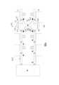
值得一提的是,於本實施例中,該第一軸線L1及該第二軸線L2上的該等真空製程腔3數量相同,於其他實施態樣中,也可依需求調整該第一軸線L1及該第二軸線L2上的真空製程腔數量,此時,該第一、第二旋轉腔41、42的配置如圖7所示。其中,該第一旋轉腔41的側開口413及該第二旋轉腔42的側開口423沿一第三軸線L3間隔設置,該第三軸線L3與該第一軸線L1及該第二軸線L2呈一夾角。It is worth mentioning that in this embodiment, the number of
該回流裝置5跨設在該第一軸線L1及該第二軸線L2上,且與該旋轉裝置4位於該第一軸線L1及該第二軸線L2的兩相反側,並銜接該卸載腔體37及該裝載腔體31,用於將該待鍍物9自該承載裝置2的載具21卸離,再將該載具21回流並裝載下一個新的待鍍物(圖未示)。較佳的,該回流裝置5能整合設備前段模組(Equipment Front End Module;EFEM),達到自動化入出料的目的。The
應說明的是,該等真空製程腔3能依據不同的製程需求而彈性配置為不同的功能腔體,例如依序連接該第一旋轉腔41的後開口411、該第一旋轉腔41的前開口412、該第二旋轉腔42的前開口422,及該第二旋轉腔42的後開口421的該等真空製程腔3分別為以下幾種腔體的配置方式:It should be noted that the
一、該除氣腔體32、該清潔腔體33、該第一鍍膜腔體34,及該第二鍍膜腔體35(同本實施例的配置)。1. The
二、該清潔腔體33、該清潔腔體33、該第一鍍膜腔體34,及該第二鍍膜腔體35。其目的在於可於不同的真空製程腔3內對於該待鍍物9的兩相反側進行清潔。2. The cleaning
三、該清潔腔體33、該第一鍍膜腔體34、該第二鍍膜腔體35,及該第二鍍膜腔體35。其目的在於藉由設置兩個第二鍍膜腔體35能增加鍍膜的膜厚。3. The cleaning
四、該清潔腔體33、該第一鍍膜腔體34、該第二鍍膜腔體35,及該第一鍍膜腔體34。舉例來說,該第一鍍膜腔體34可以是鍍不鏽鋼(SUS),該第二鍍膜腔體35則可以是鍍銅(Cu),藉此能達到SUS-Cu-SUS的鍍膜層,應用於例如EMI鍍膜。4. The cleaning
五、該清潔腔體33、該第一鍍膜腔體34、該第二鍍膜腔體35,及一第三鍍膜腔體(圖未示)。舉例來說,該第一鍍膜腔體34是鍍鈦(Ti)、該第二鍍膜腔體35是鍍鎳釩合金(NiV),及該第三鍍膜腔體是鍍金(Au)、銀(Ag),及銅(Cu)的其中之一,藉此能應用於晶背金屬化製程(Back Side Metal)或圖形化正面金屬製程(Front Side Metallization,FSM)。5. The cleaning
其變化態樣並不以上述的配置為限。例如,於其他實施態樣中,也能將該旋轉裝置4的中繼腔43置換成該第一鍍膜腔體34,該並用於鍍鈦,該第二鍍膜腔體35與該第二旋轉腔42的該前開口422相連接,且用於鍍鎳釩合金(NiV),該第三鍍膜腔體(圖未示)與該第二旋轉腔42的該後開口421相連接,且用於鍍金(Au)、銀(Ag),及銅(Cu)的其中之一。並不以此為限。The variation is not limited to the above configuration. For example, in other embodiments, the
若將該待鍍物9分為A面(圖未示)及B面(圖未示)兩個待加工區域,則該待鍍物9藉由本實施例將依序:一、裝設於該承載裝置的載具21內。二、進入該等除氣腔體32進行除氣。三、進入該清潔腔體33內並對A面進行清潔。四、進入該第一旋轉腔41內旋轉180°後,再使其回到該清潔腔體33內並對B面進行清潔。五、進入該第一旋轉腔41內,再使其進入該第二旋轉腔42內,接著進入該第一鍍膜腔體34內對A面進行鍍膜。六、進入該第二旋轉腔42內旋轉180°,再使其回到該第一鍍膜腔體34內對B面進行鍍膜。七、進入該第二旋轉腔42內,接著再進入該第二鍍膜腔體35內對B面進行鍍膜。八、進入該第二旋轉腔42內旋轉180°,再使其回到該第二鍍膜腔體35內對A面進行鍍膜。九、進入該緩衝腔體36,接著移出該承載裝置的載具21。If the object to be plated 9 is divided into two processing areas, namely, surface A (not shown) and surface B (not shown), the object to be plated 9 will be processed in the following order according to the present embodiment: 1. Installed in the
應說明的是,雖然藉由該第一旋轉腔41的旋轉模組414及該第二旋轉腔42的旋轉模組424能達到雙面鍍膜的功效。惟本實施例仍可單純用於單面鍍膜,此時該第一旋轉腔41的旋轉模組414及該第二旋轉腔42的旋轉模組424是用於將該載具21及該待鍍物9自第一軸線L1移動至該第二軸線L2,不以此為限。It should be noted that although the
參閱圖8,是本發明旋轉移載式立式鍍膜設備的一第一變化例,差異處在於:該第一旋轉腔41於該第一軸線L1上僅具有該後開口411(不具有該前開口412),該第二旋轉腔42於該第二軸線L2上僅具有該後開口421(不具有該前開口422),該等真空製程腔3的其中之二分別沿該第一、第二軸線L1、L2銜接在該第一、第二旋轉腔41、42的該後開口411、412。於本變化例中,該等真空製程腔3可以分別是該清潔腔體33及該第一鍍膜腔體34,也可以分別是該第一鍍膜腔體34及該第二鍍膜腔體35,不以此為限。Refer to FIG8, which is a first variation of the rotary transfer vertical coating equipment of the present invention. The difference is that the first
參閱圖9,是本發明旋轉移載式立式鍍膜設備的一第二變化例,其類似於該第一變化例,差異處在於:該第一旋轉腔41及該第二旋轉腔42間省略不設置該中繼腔43,而直接相連接。Refer to Figure 9, which is a second variation of the rotary transfer vertical coating equipment of the present invention. It is similar to the first variation, but the difference is that the
參閱圖10,是本發明旋轉移載式立式鍍膜設備的一第三變化例,差異處在於:該第一旋轉腔41的前開口412不位於該第一軸線L1上,及該第二旋轉腔42的該前開口422不位於該第二軸線L2上。較佳的,該第一旋轉腔41的前開口412、該第一旋轉腔41的側開口413、該第二旋轉腔42的前開口422,及該第二旋轉腔42的側開口423是沿一第四軸線L4共線。藉此能達到彈性配置的優點。Refer to Figure 10, which is a third variation of the rotary transfer vertical coating device of the present invention. The difference is that the
參閱圖11,是本發明旋轉移載式立式鍍膜設備的一第四變化例,其類似於該第三變化例,差異處在於:將兩個該第三變化例結合,並共用一個位於其中間的真空製程腔3。Refer to Figure 11, which is a fourth variation of the rotary transfer vertical coating equipment of the present invention, which is similar to the third variation, and the difference is that two third variations are combined and share a
參閱圖12,是本發明旋轉移載式立式鍍膜設備的一第五變化例,其類似於該第三變化例,差異處在於:該第一旋轉腔41還具有一位於該第一軸線L1上的外開口417,該第二旋轉腔42還具有一位於該第二軸線L2上的外開口427。該第一旋轉腔41的旋轉模組414還能以該頭端415朝向該外開口417,及以該尾端416朝向該外開口417。該第二旋轉腔42的旋轉模組424還能以該頭端425朝向該外開口427,及以該尾端426朝向該外開口427。Referring to FIG. 12 , it is a fifth variation of the rotary transfer vertical coating device of the present invention, which is similar to the third variation, except that the first
參閱圖13,是本發明旋轉移載式立式鍍膜設備的一第六變化例,差異處在於:待鍍物9的數量至少為二,該承載裝置2包括至少二個直立設置且適用以承載個別待鍍物9的載具21。Refer to Figure 13, which is a sixth variation of the rotary transfer type vertical coating equipment of the present invention. The difference is that:The number of
該第一旋轉腔41的旋轉模組414能同時容置及驅動該等載具21及該待鍍物9。該第一旋轉腔41的該後開口411及該前開口412分別連接二個真空製程腔3,每一真空製程腔3容置個別的載具21及待鍍物9。The
該第二旋轉腔42的旋轉模組424能同時容置及驅動該等載具21及該待鍍物9。該第二旋轉腔42的該後開口421及該前開口422分別連接二個真空製程腔3,每一真空製程腔3容置個別的載具21及待鍍物9。The
舉例說明:連接於該第一旋轉腔41的後開口411的二個真空製程腔3為除氣腔體32,連接於該前開口412的二個真空製程腔3為清潔腔體33。連接於該第二旋轉腔42的後開口421的二個真空製程腔3為第二鍍膜腔體35,連接於該前開口422的二個真空製程腔3為第一鍍膜腔體34,藉此能同時針對二個載具21及待鍍物9進行容置、輸送、除氣、清潔,及鍍膜加工,達到倍增產能的功效。惟配置方式不以此為限。For example: the two
於本變化例的其他實施態樣中(圖未示),該第一旋轉腔41的該後開口411及該前開口412也能僅分別連接一個真空製程腔3,該第二旋轉腔42的該後開口421及該前開口422也能僅分別連接一個真空製程腔3,此時,每一真空製程腔3能同時容置二個載具21及待鍍物9,不以此為限。In other embodiments of this variation (not shown), the
參閱圖4、圖14,及圖15,本發明雙面多層膜的鍍膜方法之一實施例,包含下列步驟:Referring to Figures 4, 14, and 15, one embodiment of the double-sided multi-layer film coating method of the present invention includes the following steps:
步驟81:輸送該待鍍物至其中一該真空製程腔3,該其中一真空製程腔3連接該第一旋轉腔41。Step 81: Transport the object to be plated to one of the
步驟82:於該其中一真空製程腔3內對該待鍍物9的其中一面進行除氣、清潔及濺鍍鍍膜的其中一種加工。Step 82: Perform one of the following processes: degassing, cleaning and sputter coating on one side of the
步驟83:將該待鍍物9輸送至該第一旋轉腔41,並旋轉180度後輸送回該其中一真空製程腔3。Step 83: The object to be plated 9 is transported to the first
步驟84:對該待鍍物9的其中另一面進行相同於步驟82的加工。Step 84: Perform the same processing as
步驟85:將該待鍍物9輸送至該第一旋轉腔41,且旋轉該待鍍物9後,將該待鍍物9自該側開口413移出該第一旋轉腔41。Step 85: The object to be plated 9 is transported to the first
步驟91:將該待鍍物9自該第二旋轉腔42的側開口423輸送進入該第二旋轉腔42。Step 91: The object to be plated 9 is transported into the second
步驟92:該第二旋轉腔42旋轉該待鍍物9,並使其自該後開口421輸送至該其中另一真空製程腔3,並於該其中另一真空製程腔3內對該待鍍物9的其中一個面進行除氣、清潔及濺鍍鍍膜的其中一種加工。Step 92: The second
步驟93:將該待鍍物9自該其中另一真空製程腔3輸送至該第二旋轉腔42,並於該第二旋轉腔42將該待鍍物9旋轉180度後,將該待鍍物9自該第二旋轉腔42輸送回該其中另一真空製程腔3。Step 93: The object to be plated 9 is transported from the other
步驟94:於該其中一真空製程腔3內對該待鍍物9的其中另一面進行相同於步驟92的加工。Step 94: Perform the same processing as
步驟95(步驟86):將該待鍍物9移入又另一真空製程腔3。Step 95 (Step 86): Move the object to be plated 9 into another
其中,步驟95(步驟86)對於步驟81至步驟85而言,該又另一真空製程腔3可以是該清潔腔體33、該第一鍍膜腔體34、該第二旋轉腔42、該第二鍍膜腔體35、該緩衝腔體36,及該卸載腔體37的其中之一;對於步驟91至步驟94而言,該又另一真空製程腔3可以是該第一鍍膜腔體34、該第二鍍膜腔體35、該緩衝腔體36,及該卸載腔體37的其中之一,但不以此為限。Among them, step 95 (step 86) for
經由以上的說明,可將前述實施例的優點歸納如下:Through the above description, the advantages of the aforementioned embodiments can be summarized as follows:
一、本發明藉由設置該旋轉裝置4,使得該清潔腔體33能對該待鍍物9的相反兩面進行清潔,及該第一鍍膜腔體34及該第二鍍膜腔體35能對該待鍍物9的相反兩面進行鍍膜,可以減少真空製程腔3的數量,而由於真空製程腔3須消耗大量的能源來維持真空度,藉由減少真空製程腔3的數量能同時降低能源消耗,而達到節能減碳及降低營運成本的功效。此外,相較於習知鍍膜設備必須倍數設置真空鍍膜腔以達到雙面鍍膜的目的,一旦僅需單面鍍膜時,另一側(無須被鍍膜的一側)的真空鍍膜腔將無效用。而當本實施例適用於單面鍍膜時,將不會產生無效的第一鍍膜腔體34或第二鍍膜腔體35,達到提高生產靈活性的優點。1. The present invention, by providing the
二、該旋轉裝置4連接的該等真空製程腔3皆可共用該第一旋轉腔41及該第二旋轉腔42,故可減少設置真空腔的數量,進一步減少佔地面積,藉此能提高無塵室的使用坪效。Second, the
三、藉由沿該第一軸線L1及該第二軸線L2排列的該真空製程腔3、該旋轉裝置4,及該回流裝置5,可避免設備在該第一軸線L1及該第二軸線L2的延伸方向上的長度過長,達到更易於彈性裝設的優點。3. By arranging the
四、藉由該承載裝置2的載具21的移動路徑在一水平面上,使得設備的高度得以下降,避免設備受到廠房高度限制,及避免因設備高度較高而導致維護困難,達到易於設置及維修保養的功效。Fourth, by having the moving path of the
五、藉由該裝載腔體31及該卸載腔體37相鄰,使得該承載裝置2回流的路程縮短,除了能減少本發明於實際運轉時所需的承載裝置2的載具21的數量,減少設備的建置成本之外,也能減少因回流而產生的能源消耗,及零配件因耗損或保養而產生的維護成本。此外,回流路程縮短也能有效避免承載裝置2的載具21因長時間暴露在大氣環境下而吸附過多的水分子,藉此降低除氣所需的時間及能源消耗,達到節能減碳的優點。5. By making the
綜上所述,本發明旋轉移載式立式鍍膜設備確實能達成本發明之目的。In summary, the rotary transfer vertical coating equipment of the present invention can indeed achieve the purpose of the present invention.
惟以上所述者,僅為本發明之實施例而已,當不能以此限定本發明實施之範圍,凡是依本發明申請專利範圍及專利說明書內容所作之簡單的等效變化與修飾,皆仍屬本發明專利涵蓋之範圍內。However, the above is only an example of the implementation of the present invention, and it cannot be used to limit the scope of the implementation of the present invention. All simple equivalent changes and modifications made according to the scope of the patent application of the present invention and the content of the patent specification are still within the scope of the patent of the present invention.
2:承載裝置 21:載具 3:真空製程腔 31:裝載腔體 32:除氣腔體 33:清潔腔體 34:第一鍍膜腔體 35:第二鍍膜腔體 36:緩衝腔體 37:卸載腔體 4:旋轉裝置 41:第一旋轉腔 411:後開口 412:前開口 413:側開口 414:旋轉模組 415: 頭端 416:尾端 42:第二旋轉腔 421:後開口 422:前開口 423:側開口 424:旋轉模組 425: 頭端 426:尾端 43:中繼腔 5:回流裝置 9:待鍍物 L1:第一軸線 L2:第二軸線2: Carrier21: Carrier3: Vacuum process chamber31: Loading chamber32: Degassing chamber33: Cleaning chamber34: First coating chamber35: Second coating chamber36: Buffer chamber37: Unloading chamber4: Rotating device41: First rotary chamber411: Rear opening412: Front opening413: Side opening414: Rotating module415: Head end416: Tail end42: Second rotary chamber421: Rear opening422: Front opening423: Side opening424: Rotating module425: Head end426: Tail end43: Relay chamber5: Reflow device9: Object to be platedL1: First axisL2: Second axis
Claims (18)
Translated fromChinesePriority Applications (1)
| Application Number | Priority Date | Filing Date | Title |
|---|---|---|---|
| TW111133992ATWI843196B (en) | 2022-09-08 | 2022-09-08 | Rotary transfer vertical coating equipment and double-sided multi-layer coating method |
Applications Claiming Priority (1)
| Application Number | Priority Date | Filing Date | Title |
|---|---|---|---|
| TW111133992ATWI843196B (en) | 2022-09-08 | 2022-09-08 | Rotary transfer vertical coating equipment and double-sided multi-layer coating method |
Publications (2)
| Publication Number | Publication Date |
|---|---|
| TW202411446A TW202411446A (en) | 2024-03-16 |
| TWI843196Btrue TWI843196B (en) | 2024-05-21 |
Family
ID=91228017
Family Applications (1)
| Application Number | Title | Priority Date | Filing Date |
|---|---|---|---|
| TW111133992ATWI843196B (en) | 2022-09-08 | 2022-09-08 | Rotary transfer vertical coating equipment and double-sided multi-layer coating method |
Country Status (1)
| Country | Link |
|---|---|
| TW (1) | TWI843196B (en) |
Citations (10)
| Publication number | Priority date | Publication date | Assignee | Title |
|---|---|---|---|---|
| US4500407A (en)* | 1983-07-19 | 1985-02-19 | Varian Associates, Inc. | Disk or wafer handling and coating system |
| JP2003221116A (en)* | 2002-01-30 | 2003-08-05 | Mitsubishi Heavy Ind Ltd | Vacuum indoor travelling control device of carrier carriage |
| TW200744928A (en)* | 2006-04-19 | 2007-12-16 | Ulvac Inc | Longitudinal substrate transporting apparatus and film forming apparatus |
| EP1668166B1 (en)* | 2003-09-03 | 2008-07-02 | OTB Group B.V. | System and method for treating substrates |
| US20110192344A1 (en)* | 2003-10-15 | 2011-08-11 | Anelva Corporation | Film forming apparatus |
| TW201248760A (en)* | 2011-02-21 | 2012-12-01 | Applied Materials Inc | System for utilization improvement of process chambers and method of operating thereof |
| CN103540905A (en)* | 2008-12-09 | 2014-01-29 | 佳能安内华股份有限公司 | Rack and pinion mechanism, vacuum processing apparatus, method of driving and controlling rack and pinion mechanism, drive control program, and recording medium |
| TW201542300A (en)* | 2014-02-04 | 2015-11-16 | Applied Materials Inc | System for depositing one or more layers on a substrate supported by a carrier ane method using the same |
| CN112647054A (en)* | 2020-12-23 | 2021-04-13 | 深圳市捷佳伟创新能源装备股份有限公司 | Double-sided coating system and double-sided coating method |
| TWM636483U (en)* | 2022-09-08 | 2023-01-11 | 凌嘉科技股份有限公司 | Rotary transfer type vertical coating equipment |
- 2022
- 2022-09-08TWTW111133992Apatent/TWI843196B/enactive
Patent Citations (10)
| Publication number | Priority date | Publication date | Assignee | Title |
|---|---|---|---|---|
| US4500407A (en)* | 1983-07-19 | 1985-02-19 | Varian Associates, Inc. | Disk or wafer handling and coating system |
| JP2003221116A (en)* | 2002-01-30 | 2003-08-05 | Mitsubishi Heavy Ind Ltd | Vacuum indoor travelling control device of carrier carriage |
| EP1668166B1 (en)* | 2003-09-03 | 2008-07-02 | OTB Group B.V. | System and method for treating substrates |
| US20110192344A1 (en)* | 2003-10-15 | 2011-08-11 | Anelva Corporation | Film forming apparatus |
| TW200744928A (en)* | 2006-04-19 | 2007-12-16 | Ulvac Inc | Longitudinal substrate transporting apparatus and film forming apparatus |
| CN103540905A (en)* | 2008-12-09 | 2014-01-29 | 佳能安内华股份有限公司 | Rack and pinion mechanism, vacuum processing apparatus, method of driving and controlling rack and pinion mechanism, drive control program, and recording medium |
| TW201248760A (en)* | 2011-02-21 | 2012-12-01 | Applied Materials Inc | System for utilization improvement of process chambers and method of operating thereof |
| TW201542300A (en)* | 2014-02-04 | 2015-11-16 | Applied Materials Inc | System for depositing one or more layers on a substrate supported by a carrier ane method using the same |
| CN112647054A (en)* | 2020-12-23 | 2021-04-13 | 深圳市捷佳伟创新能源装备股份有限公司 | Double-sided coating system and double-sided coating method |
| TWM636483U (en)* | 2022-09-08 | 2023-01-11 | 凌嘉科技股份有限公司 | Rotary transfer type vertical coating equipment |
Also Published As
| Publication number | Publication date |
|---|---|
| TW202411446A (en) | 2024-03-16 |
Similar Documents
| Publication | Publication Date | Title |
|---|---|---|
| KR100843374B1 (en) | Substrate processing apparatus and substrate processing method | |
| JP3629371B2 (en) | Film forming apparatus and film forming method | |
| US11732349B2 (en) | In-line coater for vacuum deposition of thin film coatings | |
| CN102465270B (en) | Conducting film, preparation device thereof and preparation method thereof | |
| WO2007013363A1 (en) | Vacuum treatment apparatus | |
| CN218642821U (en) | Rotary load-shifting type vertical film coating equipment | |
| CN101376964B (en) | Sputtering type film coating apparatus and film coating method | |
| TWM636483U (en) | Rotary transfer type vertical coating equipment | |
| TWI843196B (en) | Rotary transfer vertical coating equipment and double-sided multi-layer coating method | |
| JPH10140351A (en) | Inline type vacuum film forming device | |
| CN109468611B (en) | Vacuum coating device | |
| KR101841980B1 (en) | Film forming apparatus | |
| CN201924072U (en) | Conducting film preparation device | |
| CN219435891U (en) | Double-sided film plating device | |
| JP2008202146A (en) | Vertical type chemical vapor deposition system, and film deposition method using the system | |
| CN117230423A (en) | Parallel coating equipment and coating method of multilayer film | |
| CN117702070A (en) | Rotary transfer type vertical film plating equipment and film plating method of double-sided multilayer film | |
| JP6055229B2 (en) | To-be-processed object conveyance mechanism and vacuum processing apparatus | |
| JP2004083997A (en) | Vertical type chemical vapor deposition system and deposition method using this system | |
| TWM636484U (en) | End return type double-sided vertical coating equipment | |
| TWI471966B (en) | Substrate processing system and substrate processing method | |
| JP3753896B2 (en) | Magnetron sputtering equipment | |
| TWI896881B (en) | Parallel film coating equipment and multi-layer film coating method | |
| KR20130060010A (en) | Apparatus for depositing multi layer of thin film | |
| TWI820896B (en) | End-return double-sided vertical coating equipment |