TWI839611B - Indoor air pollution prevention system - Google Patents
Indoor air pollution prevention systemDownload PDFInfo
- Publication number
- TWI839611B TWI839611BTW110115675ATW110115675ATWI839611BTW I839611 BTWI839611 BTW I839611BTW 110115675 ATW110115675 ATW 110115675ATW 110115675 ATW110115675 ATW 110115675ATW I839611 BTWI839611 BTW I839611B
- Authority
- TW
- Taiwan
- Prior art keywords
- indoor
- gas detection
- air
- air pollution
- detection module
- Prior art date
Links
Images


Classifications
- F—MECHANICAL ENGINEERING; LIGHTING; HEATING; WEAPONS; BLASTING
- F24—HEATING; RANGES; VENTILATING
- F24F—AIR-CONDITIONING; AIR-HUMIDIFICATION; VENTILATION; USE OF AIR CURRENTS FOR SCREENING
- F24F7/00—Ventilation
- F24F7/003—Ventilation in combination with air cleaning
- A—HUMAN NECESSITIES
- A61—MEDICAL OR VETERINARY SCIENCE; HYGIENE
- A61L—METHODS OR APPARATUS FOR STERILISING MATERIALS OR OBJECTS IN GENERAL; DISINFECTION, STERILISATION OR DEODORISATION OF AIR; CHEMICAL ASPECTS OF BANDAGES, DRESSINGS, ABSORBENT PADS OR SURGICAL ARTICLES; MATERIALS FOR BANDAGES, DRESSINGS, ABSORBENT PADS OR SURGICAL ARTICLES
- A61L9/00—Disinfection, sterilisation or deodorisation of air
- A61L9/01—Deodorant compositions
- A61L9/014—Deodorant compositions containing sorbent material, e.g. activated carbon
- B—PERFORMING OPERATIONS; TRANSPORTING
- B01—PHYSICAL OR CHEMICAL PROCESSES OR APPARATUS IN GENERAL
- B01D—SEPARATION
- B01D46/00—Filters or filtering processes specially modified for separating dispersed particles from gases or vapours
- B01D46/42—Auxiliary equipment or operation thereof
- B01D46/429—Means for wireless communication
- B—PERFORMING OPERATIONS; TRANSPORTING
- B01—PHYSICAL OR CHEMICAL PROCESSES OR APPARATUS IN GENERAL
- B01D—SEPARATION
- B01D46/00—Filters or filtering processes specially modified for separating dispersed particles from gases or vapours
- B01D46/42—Auxiliary equipment or operation thereof
- B01D46/44—Auxiliary equipment or operation thereof controlling filtration
- B01D46/442—Auxiliary equipment or operation thereof controlling filtration by measuring the concentration of particles
- B—PERFORMING OPERATIONS; TRANSPORTING
- B01—PHYSICAL OR CHEMICAL PROCESSES OR APPARATUS IN GENERAL
- B01D—SEPARATION
- B01D46/00—Filters or filtering processes specially modified for separating dispersed particles from gases or vapours
- B01D46/42—Auxiliary equipment or operation thereof
- B01D46/44—Auxiliary equipment or operation thereof controlling filtration
- B01D46/46—Auxiliary equipment or operation thereof controlling filtration automatic
- F—MECHANICAL ENGINEERING; LIGHTING; HEATING; WEAPONS; BLASTING
- F24—HEATING; RANGES; VENTILATING
- F24C—DOMESTIC STOVES OR RANGES ; DETAILS OF DOMESTIC STOVES OR RANGES, OF GENERAL APPLICATION
- F24C15/00—Details
- F24C15/20—Removing cooking fumes
- F24C15/2021—Arrangement or mounting of control or safety systems
- F—MECHANICAL ENGINEERING; LIGHTING; HEATING; WEAPONS; BLASTING
- F24—HEATING; RANGES; VENTILATING
- F24F—AIR-CONDITIONING; AIR-HUMIDIFICATION; VENTILATION; USE OF AIR CURRENTS FOR SCREENING
- F24F11/00—Control or safety arrangements
- F24F11/0001—Control or safety arrangements for ventilation
- F—MECHANICAL ENGINEERING; LIGHTING; HEATING; WEAPONS; BLASTING
- F24—HEATING; RANGES; VENTILATING
- F24F—AIR-CONDITIONING; AIR-HUMIDIFICATION; VENTILATION; USE OF AIR CURRENTS FOR SCREENING
- F24F11/00—Control or safety arrangements
- F24F11/50—Control or safety arrangements characterised by user interfaces or communication
- F24F11/56—Remote control
- F—MECHANICAL ENGINEERING; LIGHTING; HEATING; WEAPONS; BLASTING
- F24—HEATING; RANGES; VENTILATING
- F24F—AIR-CONDITIONING; AIR-HUMIDIFICATION; VENTILATION; USE OF AIR CURRENTS FOR SCREENING
- F24F11/00—Control or safety arrangements
- F24F11/62—Control or safety arrangements characterised by the type of control or by internal processing, e.g. using fuzzy logic, adaptive control or estimation of values
- F24F11/63—Electronic processing
- F24F11/64—Electronic processing using pre-stored data
- F—MECHANICAL ENGINEERING; LIGHTING; HEATING; WEAPONS; BLASTING
- F24—HEATING; RANGES; VENTILATING
- F24F—AIR-CONDITIONING; AIR-HUMIDIFICATION; VENTILATION; USE OF AIR CURRENTS FOR SCREENING
- F24F11/00—Control or safety arrangements
- F24F11/62—Control or safety arrangements characterised by the type of control or by internal processing, e.g. using fuzzy logic, adaptive control or estimation of values
- F24F11/63—Electronic processing
- F24F11/65—Electronic processing for selecting an operating mode
- F—MECHANICAL ENGINEERING; LIGHTING; HEATING; WEAPONS; BLASTING
- F24—HEATING; RANGES; VENTILATING
- F24F—AIR-CONDITIONING; AIR-HUMIDIFICATION; VENTILATION; USE OF AIR CURRENTS FOR SCREENING
- F24F11/00—Control or safety arrangements
- F24F11/70—Control systems characterised by their outputs; Constructional details thereof
- F24F11/72—Control systems characterised by their outputs; Constructional details thereof for controlling the supply of treated air, e.g. its pressure
- F—MECHANICAL ENGINEERING; LIGHTING; HEATING; WEAPONS; BLASTING
- F24—HEATING; RANGES; VENTILATING
- F24F—AIR-CONDITIONING; AIR-HUMIDIFICATION; VENTILATION; USE OF AIR CURRENTS FOR SCREENING
- F24F13/00—Details common to, or for air-conditioning, air-humidification, ventilation or use of air currents for screening
- F24F13/08—Air-flow control members, e.g. louvres, grilles, flaps or guide plates
- F24F13/10—Air-flow control members, e.g. louvres, grilles, flaps or guide plates movable, e.g. dampers
- F—MECHANICAL ENGINEERING; LIGHTING; HEATING; WEAPONS; BLASTING
- F24—HEATING; RANGES; VENTILATING
- F24F—AIR-CONDITIONING; AIR-HUMIDIFICATION; VENTILATION; USE OF AIR CURRENTS FOR SCREENING
- F24F13/00—Details common to, or for air-conditioning, air-humidification, ventilation or use of air currents for screening
- F24F13/28—Arrangement or mounting of filters
- F—MECHANICAL ENGINEERING; LIGHTING; HEATING; WEAPONS; BLASTING
- F24—HEATING; RANGES; VENTILATING
- F24F—AIR-CONDITIONING; AIR-HUMIDIFICATION; VENTILATION; USE OF AIR CURRENTS FOR SCREENING
- F24F7/00—Ventilation
- F24F7/007—Ventilation with forced flow
- F—MECHANICAL ENGINEERING; LIGHTING; HEATING; WEAPONS; BLASTING
- F24—HEATING; RANGES; VENTILATING
- F24F—AIR-CONDITIONING; AIR-HUMIDIFICATION; VENTILATION; USE OF AIR CURRENTS FOR SCREENING
- F24F7/00—Ventilation
- F24F7/04—Ventilation with ducting systems, e.g. by double walls; with natural circulation
- F24F7/06—Ventilation with ducting systems, e.g. by double walls; with natural circulation with forced air circulation, e.g. by fan positioning of a ventilator in or against a conduit
- F24F7/08—Ventilation with ducting systems, e.g. by double walls; with natural circulation with forced air circulation, e.g. by fan positioning of a ventilator in or against a conduit with separate ducts for supplied and exhausted air with provisions for reversal of the input and output systems
- F—MECHANICAL ENGINEERING; LIGHTING; HEATING; WEAPONS; BLASTING
- F24—HEATING; RANGES; VENTILATING
- F24F—AIR-CONDITIONING; AIR-HUMIDIFICATION; VENTILATION; USE OF AIR CURRENTS FOR SCREENING
- F24F8/00—Treatment, e.g. purification, of air supplied to human living or working spaces otherwise than by heating, cooling, humidifying or drying
- F24F8/10—Treatment, e.g. purification, of air supplied to human living or working spaces otherwise than by heating, cooling, humidifying or drying by separation, e.g. by filtering
- F24F8/108—Treatment, e.g. purification, of air supplied to human living or working spaces otherwise than by heating, cooling, humidifying or drying by separation, e.g. by filtering using dry filter elements
- F—MECHANICAL ENGINEERING; LIGHTING; HEATING; WEAPONS; BLASTING
- F24—HEATING; RANGES; VENTILATING
- F24F—AIR-CONDITIONING; AIR-HUMIDIFICATION; VENTILATION; USE OF AIR CURRENTS FOR SCREENING
- F24F8/00—Treatment, e.g. purification, of air supplied to human living or working spaces otherwise than by heating, cooling, humidifying or drying
- F24F8/10—Treatment, e.g. purification, of air supplied to human living or working spaces otherwise than by heating, cooling, humidifying or drying by separation, e.g. by filtering
- F24F8/15—Treatment, e.g. purification, of air supplied to human living or working spaces otherwise than by heating, cooling, humidifying or drying by separation, e.g. by filtering by chemical means
- F24F8/158—Treatment, e.g. purification, of air supplied to human living or working spaces otherwise than by heating, cooling, humidifying or drying by separation, e.g. by filtering by chemical means using active carbon
- F—MECHANICAL ENGINEERING; LIGHTING; HEATING; WEAPONS; BLASTING
- F24—HEATING; RANGES; VENTILATING
- F24F—AIR-CONDITIONING; AIR-HUMIDIFICATION; VENTILATION; USE OF AIR CURRENTS FOR SCREENING
- F24F8/00—Treatment, e.g. purification, of air supplied to human living or working spaces otherwise than by heating, cooling, humidifying or drying
- F24F8/10—Treatment, e.g. purification, of air supplied to human living or working spaces otherwise than by heating, cooling, humidifying or drying by separation, e.g. by filtering
- F24F8/15—Treatment, e.g. purification, of air supplied to human living or working spaces otherwise than by heating, cooling, humidifying or drying by separation, e.g. by filtering by chemical means
- F24F8/167—Treatment, e.g. purification, of air supplied to human living or working spaces otherwise than by heating, cooling, humidifying or drying by separation, e.g. by filtering by chemical means using catalytic reactions
- F—MECHANICAL ENGINEERING; LIGHTING; HEATING; WEAPONS; BLASTING
- F24—HEATING; RANGES; VENTILATING
- F24F—AIR-CONDITIONING; AIR-HUMIDIFICATION; VENTILATION; USE OF AIR CURRENTS FOR SCREENING
- F24F8/00—Treatment, e.g. purification, of air supplied to human living or working spaces otherwise than by heating, cooling, humidifying or drying
- F24F8/20—Treatment, e.g. purification, of air supplied to human living or working spaces otherwise than by heating, cooling, humidifying or drying by sterilisation
- F—MECHANICAL ENGINEERING; LIGHTING; HEATING; WEAPONS; BLASTING
- F24—HEATING; RANGES; VENTILATING
- F24F—AIR-CONDITIONING; AIR-HUMIDIFICATION; VENTILATION; USE OF AIR CURRENTS FOR SCREENING
- F24F8/00—Treatment, e.g. purification, of air supplied to human living or working spaces otherwise than by heating, cooling, humidifying or drying
- F24F8/30—Treatment, e.g. purification, of air supplied to human living or working spaces otherwise than by heating, cooling, humidifying or drying by ionisation
- F—MECHANICAL ENGINEERING; LIGHTING; HEATING; WEAPONS; BLASTING
- F24—HEATING; RANGES; VENTILATING
- F24F—AIR-CONDITIONING; AIR-HUMIDIFICATION; VENTILATION; USE OF AIR CURRENTS FOR SCREENING
- F24F8/00—Treatment, e.g. purification, of air supplied to human living or working spaces otherwise than by heating, cooling, humidifying or drying
- F24F8/95—Treatment, e.g. purification, of air supplied to human living or working spaces otherwise than by heating, cooling, humidifying or drying specially adapted for specific purposes
- F24F8/98—Treatment, e.g. purification, of air supplied to human living or working spaces otherwise than by heating, cooling, humidifying or drying specially adapted for specific purposes for removing ozone
- G—PHYSICS
- G01—MEASURING; TESTING
- G01N—INVESTIGATING OR ANALYSING MATERIALS BY DETERMINING THEIR CHEMICAL OR PHYSICAL PROPERTIES
- G01N33/00—Investigating or analysing materials by specific methods not covered by groups G01N1/00 - G01N31/00
- G01N33/0004—Gaseous mixtures, e.g. polluted air
- G01N33/0009—General constructional details of gas analysers, e.g. portable test equipment
- G01N33/0062—General constructional details of gas analysers, e.g. portable test equipment concerning the measuring method or the display, e.g. intermittent measurement or digital display
- G01N33/0063—General constructional details of gas analysers, e.g. portable test equipment concerning the measuring method or the display, e.g. intermittent measurement or digital display using a threshold to release an alarm or displaying means
- G—PHYSICS
- G01—MEASURING; TESTING
- G01N—INVESTIGATING OR ANALYSING MATERIALS BY DETERMINING THEIR CHEMICAL OR PHYSICAL PROPERTIES
- G01N33/00—Investigating or analysing materials by specific methods not covered by groups G01N1/00 - G01N31/00
- G01N33/0004—Gaseous mixtures, e.g. polluted air
- G01N33/0009—General constructional details of gas analysers, e.g. portable test equipment
- G01N33/0073—Control unit therefor
- G01N33/0075—Control unit therefor for multiple spatially distributed sensors, e.g. for environmental monitoring
- G—PHYSICS
- G05—CONTROLLING; REGULATING
- G05B—CONTROL OR REGULATING SYSTEMS IN GENERAL; FUNCTIONAL ELEMENTS OF SUCH SYSTEMS; MONITORING OR TESTING ARRANGEMENTS FOR SUCH SYSTEMS OR ELEMENTS
- G05B15/00—Systems controlled by a computer
- G05B15/02—Systems controlled by a computer electric
- A—HUMAN NECESSITIES
- A61—MEDICAL OR VETERINARY SCIENCE; HYGIENE
- A61L—METHODS OR APPARATUS FOR STERILISING MATERIALS OR OBJECTS IN GENERAL; DISINFECTION, STERILISATION OR DEODORISATION OF AIR; CHEMICAL ASPECTS OF BANDAGES, DRESSINGS, ABSORBENT PADS OR SURGICAL ARTICLES; MATERIALS FOR BANDAGES, DRESSINGS, ABSORBENT PADS OR SURGICAL ARTICLES
- A61L2209/00—Aspects relating to disinfection, sterilisation or deodorisation of air
- A61L2209/10—Apparatus features
- A61L2209/11—Apparatus for controlling air treatment
- A61L2209/111—Sensor means, e.g. motion, brightness, scent, contaminant sensors
- A—HUMAN NECESSITIES
- A61—MEDICAL OR VETERINARY SCIENCE; HYGIENE
- A61L—METHODS OR APPARATUS FOR STERILISING MATERIALS OR OBJECTS IN GENERAL; DISINFECTION, STERILISATION OR DEODORISATION OF AIR; CHEMICAL ASPECTS OF BANDAGES, DRESSINGS, ABSORBENT PADS OR SURGICAL ARTICLES; MATERIALS FOR BANDAGES, DRESSINGS, ABSORBENT PADS OR SURGICAL ARTICLES
- A61L2209/00—Aspects relating to disinfection, sterilisation or deodorisation of air
- A61L2209/10—Apparatus features
- A61L2209/14—Filtering means
- B—PERFORMING OPERATIONS; TRANSPORTING
- B01—PHYSICAL OR CHEMICAL PROCESSES OR APPARATUS IN GENERAL
- B01D—SEPARATION
- B01D2279/00—Filters adapted for separating dispersed particles from gases or vapours specially modified for specific uses
- B01D2279/50—Filters adapted for separating dispersed particles from gases or vapours specially modified for specific uses for air conditioning
- F—MECHANICAL ENGINEERING; LIGHTING; HEATING; WEAPONS; BLASTING
- F24—HEATING; RANGES; VENTILATING
- F24F—AIR-CONDITIONING; AIR-HUMIDIFICATION; VENTILATION; USE OF AIR CURRENTS FOR SCREENING
- F24F11/00—Control or safety arrangements
- F24F11/0001—Control or safety arrangements for ventilation
- F24F2011/0002—Control or safety arrangements for ventilation for admittance of outside air
- F—MECHANICAL ENGINEERING; LIGHTING; HEATING; WEAPONS; BLASTING
- F24—HEATING; RANGES; VENTILATING
- F24F—AIR-CONDITIONING; AIR-HUMIDIFICATION; VENTILATION; USE OF AIR CURRENTS FOR SCREENING
- F24F2110/00—Control inputs relating to air properties
- F24F2110/10—Temperature
- F—MECHANICAL ENGINEERING; LIGHTING; HEATING; WEAPONS; BLASTING
- F24—HEATING; RANGES; VENTILATING
- F24F—AIR-CONDITIONING; AIR-HUMIDIFICATION; VENTILATION; USE OF AIR CURRENTS FOR SCREENING
- F24F2110/00—Control inputs relating to air properties
- F24F2110/20—Humidity
- F—MECHANICAL ENGINEERING; LIGHTING; HEATING; WEAPONS; BLASTING
- F24—HEATING; RANGES; VENTILATING
- F24F—AIR-CONDITIONING; AIR-HUMIDIFICATION; VENTILATION; USE OF AIR CURRENTS FOR SCREENING
- F24F2110/00—Control inputs relating to air properties
- F24F2110/50—Air quality properties
- F—MECHANICAL ENGINEERING; LIGHTING; HEATING; WEAPONS; BLASTING
- F24—HEATING; RANGES; VENTILATING
- F24F—AIR-CONDITIONING; AIR-HUMIDIFICATION; VENTILATION; USE OF AIR CURRENTS FOR SCREENING
- F24F2110/00—Control inputs relating to air properties
- F24F2110/50—Air quality properties
- F24F2110/64—Airborne particle content
- F—MECHANICAL ENGINEERING; LIGHTING; HEATING; WEAPONS; BLASTING
- F24—HEATING; RANGES; VENTILATING
- F24F—AIR-CONDITIONING; AIR-HUMIDIFICATION; VENTILATION; USE OF AIR CURRENTS FOR SCREENING
- F24F2110/00—Control inputs relating to air properties
- F24F2110/50—Air quality properties
- F24F2110/65—Concentration of specific substances or contaminants
- F24F2110/66—Volatile organic compounds [VOC]
- F—MECHANICAL ENGINEERING; LIGHTING; HEATING; WEAPONS; BLASTING
- F24—HEATING; RANGES; VENTILATING
- F24F—AIR-CONDITIONING; AIR-HUMIDIFICATION; VENTILATION; USE OF AIR CURRENTS FOR SCREENING
- F24F2110/00—Control inputs relating to air properties
- F24F2110/50—Air quality properties
- F24F2110/65—Concentration of specific substances or contaminants
- F24F2110/70—Carbon dioxide
- Y—GENERAL TAGGING OF NEW TECHNOLOGICAL DEVELOPMENTS; GENERAL TAGGING OF CROSS-SECTIONAL TECHNOLOGIES SPANNING OVER SEVERAL SECTIONS OF THE IPC; TECHNICAL SUBJECTS COVERED BY FORMER USPC CROSS-REFERENCE ART COLLECTIONS [XRACs] AND DIGESTS
- Y02—TECHNOLOGIES OR APPLICATIONS FOR MITIGATION OR ADAPTATION AGAINST CLIMATE CHANGE
- Y02B—CLIMATE CHANGE MITIGATION TECHNOLOGIES RELATED TO BUILDINGS, e.g. HOUSING, HOUSE APPLIANCES OR RELATED END-USER APPLICATIONS
- Y02B30/00—Energy efficient heating, ventilation or air conditioning [HVAC]
- Y02B30/70—Efficient control or regulation technologies, e.g. for control of refrigerant flow, motor or heating
Landscapes
- Engineering & Computer Science (AREA)
- Chemical & Material Sciences (AREA)
- Combustion & Propulsion (AREA)
- General Engineering & Computer Science (AREA)
- Mechanical Engineering (AREA)
- Health & Medical Sciences (AREA)
- Chemical Kinetics & Catalysis (AREA)
- Life Sciences & Earth Sciences (AREA)
- Physics & Mathematics (AREA)
- Signal Processing (AREA)
- General Health & Medical Sciences (AREA)
- General Physics & Mathematics (AREA)
- Food Science & Technology (AREA)
- Medicinal Chemistry (AREA)
- Analytical Chemistry (AREA)
- Biochemistry (AREA)
- Immunology (AREA)
- Pathology (AREA)
- Mathematical Physics (AREA)
- Fuzzy Systems (AREA)
- General Chemical & Material Sciences (AREA)
- Materials Engineering (AREA)
- Public Health (AREA)
- Veterinary Medicine (AREA)
- Computer Networks & Wireless Communication (AREA)
- Epidemiology (AREA)
- Automation & Control Theory (AREA)
- Animal Behavior & Ethology (AREA)
- Human Computer Interaction (AREA)
- Filtering Of Dispersed Particles In Gases (AREA)
- Ventilation (AREA)
- Sampling And Sample Adjustment (AREA)
- Air Conditioning Control Device (AREA)
- Disinfection, Sterilisation Or Deodorisation Of Air (AREA)
Abstract
Description
Translated fromChinese本發明係有關一種於室內空間實施一氣體汙染交換,特別是指一種室內空汙防治系統。The present invention relates to a method for implementing a gas pollution exchange in an indoor space, and more particularly to an indoor air pollution prevention and control system.
由於人們對於生活周遭的空氣品質愈來愈重視,懸浮粒子(particulate matter,PM)例如PM1、PM2.5、PM10、二氧化碳、總揮發性有機物(Total Volatile Organic Compound,TVOC)、甲醛...等氣體,甚至於氣體中含有的微粒、氣溶膠、細菌、病毒...等,都會在環境中暴露影響人體健康,嚴重的甚至危害到生命。As people pay more and more attention to the air quality around them, suspended particles (PM) such as PM1 , PM2.5 , PM10 , carbon dioxide, total volatile organic compounds (TVOC), formaldehyde, and other gases, and even particles, aerosols, bacteria, viruses, etc. contained in the gases, will be exposed in the environment and affect human health, and in serious cases even endanger life.
而室內空氣品質並不容易掌握,除了室外空氣品質之外,室內的空調狀況、汙染源皆是影響室內空氣品質的主要因素,特別是室內空氣不流通造成的粉塵。為了改善室內的空氣環境達到良好的空氣品質狀態,人們多會利用空調機或空氣濾清器等裝置來達到改善室內空氣品質之目的。然而,空調機及空氣濾清器皆為室內空氣循環,並無法排除絕大部份的有害氣體,尤其是一氧化碳或二氧化碳等有害氣體。Indoor air quality is not easy to master. In addition to outdoor air quality, indoor air conditioning conditions and pollution sources are the main factors affecting indoor air quality, especially dust caused by poor indoor air circulation. In order to improve the indoor air environment and achieve good air quality, people often use devices such as air conditioners or air filters to achieve the purpose of improving indoor air quality. However, air conditioners and air filters are indoor air circulation and cannot eliminate most harmful gases, especially harmful gases such as carbon monoxide or carbon dioxide.
為此,能提供能即時淨化空氣品質減少在室內呼吸到有害氣體的淨化解決方案,並可隨時隨地即時監測室內空氣品質,當室內空氣品質不良時快速淨化室內空氣,乃為本發明所研發的主要課題。To this end, the main topic of this invention is to provide a purification solution that can instantly purify the air quality and reduce the harmful gases breathed in indoors, and to monitor the indoor air quality in real time anytime and anywhere, and to quickly purify the indoor air when the indoor air quality is poor.
鑒於上述習知技術缺點,本發明係為一種室內空汙防治系統,其主要目的係提供一氣體交換處理裝置智能地選擇氣體汙染交換,促使室內氣體汙染之偵測數據降至一安全偵測值,形成潔淨可安全呼吸之狀態。In view of the above-mentioned shortcomings of the prior art, the present invention is an indoor air pollution prevention system, the main purpose of which is to provide a gas exchange treatment device to intelligently select gas pollution exchange, so as to reduce the detection data of indoor gas pollution to a safe detection value, thus forming a clean and safe breathing state.
為達上述目的,本發明之室內空汙防治系統,適用於對一室內之空汙源實施交換及過濾,包含:複數個氣體偵測模組,偵測該空汙源,並傳輸一氣體偵測數據;至少一智能控制驅動處理裝置,供以接收及比對複數個該氣體偵測模組所輸出之該氣體偵測數據,並智能選擇發出一驅動指令;至少一氣體交換處理裝置,包含至少一導風機及一過濾清淨組件,其中該至少一氣體交換處理裝置接收該智能控制驅動處理裝置所發出該驅動指令,以控制一室外之一外部氣體導入或不導入在該室內之一空間,促使過濾交換該室內之該空汙源;以及至少一室內清淨過濾裝置,包含該導風機及該過濾清淨組件,接收該智能控制驅動處理裝置所發出該驅動指令,啟動過濾交換該室內之該空汙源;其中,該智能控制驅動處理裝置接收及比對該氣體偵測數據後,智能選擇該氣體交換處理裝置導入或不導入該室外之該外部氣體,以及該智能控制驅動處理裝置即時控制該室內清淨過濾裝置在一監測機制狀態下而啟動操作,促使該室內之該汙染源通過該室內清淨過濾裝置中進行過濾淨化,以致在該室內之該空汙源被過濾並交換形成一乾淨空氣。To achieve the above-mentioned purpose, the indoor air pollution prevention and control system of the present invention is suitable for implementing exchange and filtration on an indoor air pollution source, and includes: a plurality of gas detection modules, detecting the air pollution source and transmitting a gas detection data; at least one intelligent control drive processing device, for receiving and comparing the gas detection data output by the plurality of gas detection modules, and intelligently selecting and issuing a drive command; at least one gas exchange processing device, including at least one air guide fan and a filtering and purifying component, wherein the at least one gas exchange processing device receives the drive command issued by the intelligent control drive processing device to control an external gas outside an outdoor to be introduced into or not introduced into a space inside the room, so as to promote filtering and exchange of the room. and at least one indoor clean filter device, including the air guide fan and the filter clean component, receiving the driving instruction issued by the intelligent control drive processing device, and starting the filter exchange of the indoor clean filter; wherein, after receiving and comparing the gas detection data, the intelligent control drive processing device intelligently selects the gas exchange processing device The external gas is introduced into or not introduced into the outdoor, and the intelligent control driving processing device instantly controls the indoor purification filter device to start operation under a monitoring mechanism state, so that the indoor pollution source is filtered and purified in the indoor purification filter device, so that the indoor air pollution source is filtered and exchanged to form a clean air.
1:氣體偵測模組1: Gas detection module
1a:室外氣體偵測模組1a: Outdoor gas detection module
1b:室內氣體偵測模組1b: Indoor gas detection module
11:控制電路板11: Control circuit board
12:氣體偵測主體12: Gas detection subject
121:基座121: Base
1211:第一表面1211: First surface
1212:第二表面1212: Second surface
1213:雷射設置區1213: Laser setting area
1214:進氣溝槽1214: Intake groove
1214a:進氣通口1214a: Air intake vent
1214b:透光窗口1214b: light-transmitting window
1215:導氣組件承載區1215: Air guide component carrying area
1215a:通氣孔1215a: Ventilation hole
1215b:定位凸塊1215b: Positioning bump
1216:出氣溝槽1216: Vent groove
1216a:出氣通口1216a: Air outlet
1216b:第一區間1216b: First interval
1216c:第二區間1216c: Second interval
122:壓電致動器122: Piezoelectric actuator
1221:噴氣孔片1221: Air jet hole sheet
1221a:懸浮片1221a: Suspension sheet
1221b:中空孔洞1221b: Hollow hole
1221c:空隙1221c: Gap
1222:腔體框架1222: Cavity frame
1223:致動體1223: Actuator
1223a:壓電載板1223a: Piezoelectric substrate
1223b:調整共振板1223b: Adjust the resonance plate
1223c:壓電板1223c: Piezoelectric plate
1223d:壓電接腳1223d: Piezoelectric pins
1224:絕緣框架1224: Insulation frame
1225:導電框架1225: Conductive frame
1225a:導電接腳1225a: Conductive pin
1225b:導電電極1225b: Conductive electrode
1226:共振腔室1226: Resonance Chamber
1227:氣流腔室1227: Airflow chamber
123:驅動電路板123:Drive circuit board
124:雷射組件124: Laser components
125:微粒傳感器125: Particle sensor
126:外蓋126: Outer cover
1261:側板1261: Side panels
1261a:進氣框口1261a: Air intake frame
1261b:出氣框口1261b: Air outlet frame
127:氣體傳感器127: Gas sensor
13:微處理器13: Microprocessor
14:通信器14: Communicator
2:智能控制驅動處理裝置2: Intelligent control drive processing device
2a:接收驅動器2a: Receiver driver
2b:雲端處理裝置2b: Cloud processing device
21a:移動式驅動器21a: Mobile drive
22a:可攜式行動裝置22a: Portable mobile devices
3:氣體交換處理裝置3: Gas exchange treatment device
3a:新風機3a: Fresh air blower
31a:進氣通道31a: Intake channel
311a:進氣入口311a: Air intake
312a:進氣出口312a: Air intake outlet
32a:排氣通道32a: Exhaust channel
321a:排氣入口321a: Exhaust inlet
322a:排氣出口322a: Exhaust outlet
33a:循環通道33a: Circulation channel
34a:進氣閥34a: Intake valve
35a:出氣閥35a: Exhaust valve
4:室內清淨過濾裝置4: Indoor purification filter device
4a:冷氣機4a: Air conditioner
4b:排油煙機4b: Range hood
4c:抽風機4c: Exhaust fan
4d:清淨機4d: Purifier
4e:電風扇4e: Electric fan
A:室內A:Indoors
B:室外B:Outdoor
C:導風機C: Air guide fan
C1:進氣導風機C1: Intake fan
C2:出氣導風機C2: Air outlet fan
D:過濾清淨組件D: Filter and purification components
D1:活性碳D1: Activated carbon
D2:高效濾網D2: High efficiency filter
D3:沸石網D3: Zeolite Net
D4:光觸媒單元D4: Photocatalyst unit
D5:光等離子單元D5: Photoplasma unit
D6:負離子單元D6: Negative ion unit
D7:電漿離子單元D7: Plasma ion unit
第1A圖為本發明之室內空汙防治系統裝於室內之使用示意圖。Figure 1A is a schematic diagram of the indoor air pollution prevention system of the present invention installed indoors.
第1B圖為本發明之室內空汙防治系統裝於室內之另一使用示意圖。Figure 1B is another schematic diagram of the indoor air pollution prevention system of the present invention installed indoors.
第2圖為本發明室內氣體偵測模組使用示意圖。Figure 2 is a schematic diagram of the use of the indoor gas detection module of the present invention.
第3圖為本發明氣體偵測模組立體組合示意圖。Figure 3 is a schematic diagram of the three-dimensional assembly of the gas detection module of the present invention.
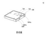
第4A圖為本發明氣體偵測主體立體組合示意圖。Figure 4A is a schematic diagram of the three-dimensional assembly of the gas detection main body of the present invention.
第4B圖為本發明氣體偵測主體另一視角立體組合示意圖。Figure 4B is a schematic diagram of another perspective three-dimensional combination of the gas detection subject of the present invention.
第4C圖為本發明氣體偵測主體立體分解示意圖。Figure 4C is a three-dimensional exploded schematic diagram of the gas detection main body of the present invention.
第5A圖為本發明基座立體示意圖。Figure 5A is a three-dimensional schematic diagram of the base of the present invention.
第5B圖為本發明基座另一視角立體示意圖。Figure 5B is a three-dimensional schematic diagram of the base of the present invention from another viewing angle.
第6圖為本發明基座結合雷射組件立體示意圖。Figure 6 is a three-dimensional schematic diagram of the base combined with the laser assembly of the present invention.
第7A圖為本發明壓電致動器與基座分解之立體示意圖。Figure 7A is a three-dimensional schematic diagram of the piezoelectric actuator and base of the present invention.
第7B圖為本發明壓電致動器與基座組合之立體示意圖。Figure 7B is a three-dimensional schematic diagram of the piezoelectric actuator and base assembly of the present invention.
第8A圖為本發明壓電致動器之立體分解示意圖。Figure 8A is a three-dimensional exploded schematic diagram of the piezoelectric actuator of the present invention.
第8B圖為本發明壓電致動器另一視角之立體分解示意圖。Figure 8B is a three-dimensional exploded schematic diagram of the piezoelectric actuator of the present invention from another viewing angle.
第9A圖為本發明壓電致動器未動作前之剖視作動示意圖。Figure 9A is a cross-sectional diagram of the piezoelectric actuator of the present invention before it is actuated.
第9B圖為本發明壓電致動器動作一之剖視作動示意圖。Figure 9B is a cross-sectional schematic diagram of the piezoelectric actuator of the present invention in
第9C圖為本發明壓電致動器動作二之剖視作動示意圖。Figure 9C is a cross-sectional diagram of the second action of the piezoelectric actuator of the present invention.
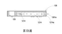
第10A圖為本發明氣體由外蓋之進氣通口進入之剖視示意圖。Figure 10A is a cross-sectional diagram of the gas of the present invention entering through the air inlet port of the outer cover.
第10B圖為本發明雷射組件發射光束通過透光窗口進入進氣溝槽之剖視示意圖。Figure 10B is a cross-sectional diagram of the laser assembly of the present invention emitting a light beam through the light-transmitting window and entering the air intake groove.
第10C圖為本發明出氣溝內的氣體被推引並通過出氣通口及出氣框口而向外部排出之剖視示意圖。Figure 10C is a cross-sectional schematic diagram showing the gas in the air outlet groove of the present invention being pushed and discharged to the outside through the air outlet port and the air outlet frame port.
第11圖為本發明氣體交換處理裝置剖視示意圖。Figure 11 is a cross-sectional schematic diagram of the gas exchange processing device of the present invention.
第12圖為本發明過濾清淨組件剖視示意圖。Figure 12 is a cross-sectional schematic diagram of the filter purification assembly of the present invention.
體現本發明特徵的實施例將在後段的說明中詳細敘述。應理解的是本發明能夠在不同的態樣上具有各種的變化,其皆不脫離本發明的範圍,且其中的說明及圖示在本質上當作說明之用,而非用以限制本發明。The embodiments that embody the features of the present invention will be described in detail in the following description. It should be understood that the present invention can have various variations in different forms, all of which do not deviate from the scope of the present invention, and the descriptions and illustrations therein are essentially for illustrative purposes rather than for limiting the present invention.
請參閱第1A圖至第2圖所示,本發明之室內空汙防治系統適用於對一室內A實施氣體交換及過濾,其包含:複數氣體偵測模組1、至少一智能控制驅動處理裝置2、至少一氣體交換處理裝置3、及室內清淨過濾裝置4,其中複數氣體偵測模組1實施偵測及過濾處理氣體汙染,並傳輸一氣體偵測數據,且複數個氣體偵測模組1包含複數室外氣體偵測模組1a及複數室內氣體偵測模組1b,其中室外氣體偵測模組1a偵測室外B之空汙源及傳輸室外B之一氣體偵測數據,而室內氣體偵測模組1b偵測室內A之空汙源及傳輸室內A之一氣體偵測數據。Please refer to FIG. 1A to FIG. 2, the indoor air pollution prevention system of the present invention is applicable to implement gas exchange and filtration in a room A, which comprises: a plurality of
至少一智能控制驅動處理裝置2,包含一接收驅動器2a及一雲端處理裝置2b,接收驅動器2a接收複數個氣體偵測模組1(室外氣體偵測模組1a、室內氣體偵測模組1b)所輸出之室外B及室內A之氣體偵測數據並上傳給雲端處理裝置2b,雲端處理裝置2b進行人工智慧運算及比對,並將比對結果予以智能選擇發出一驅動指令給接收驅動器2a,透過接收驅動器2a驅動至少一氣體交換處理裝置3及至少一室內清淨過濾裝置4予以啟動操作。本實施例中,接收驅動器2a為一移動式驅動器21a、一可攜式行動裝置22a或一穿戴式裝置之其中之一。其中,移動式驅動器21a具有一顯示器得以顯示室內A之氣體偵測數據,而可攜式行動裝置22a為一智慧型手機得以顯示室內A之氣體偵測數據,而穿戴式裝置可結合室內氣體偵測模組1b,供直接穿戴於人體上隨時即時偵測在室內A之空汙源,並傳輸一氣體偵測數據。At least one intelligent control
至少一氣體交換處理裝置3(可為一新風機3a)並具有一顯示器,供顯示室內A之氣體偵測數據,又氣體交換處理裝置3結合室外氣體偵測模組1a及室內氣體偵測模組1b,其中室內氣體偵測模組1b驅動控制氣體交換處理裝置3之啟動操作,而智能控制驅動處理裝置2接收室外氣體偵測模組1a所輸出室外B之氣體偵測數據及室內氣體偵測模組1b所輸出室內A之氣體偵測數據,經比對後,智能選擇發出一驅動指令給室內氣體偵測模組1b控制氣體交換處理裝置3啟動操作,控制室外B之外部氣體導入或不導入在室內A,以確保氣體交換處理裝置3過濾空汙源被交換形成一乾淨空氣導入室內A。At least one gas exchange processing device 3 (which may be a fresh air blower 3a) has a display for displaying the gas detection data of the room A. The gas
且氣體交換處理裝置3包含:一進氣通道31a、一排氣通道32a、一循環通道33a,進氣通道31a具有至少一進氣入口311a及至少一進氣出口312a,排氣通道32a具有至少一排氣入口321a及至少一排氣出口322a,而至少一室外氣體偵測模組1a設置於進氣通道31a之進氣入口311a,至少一室內氣體偵測模組1b設置於進氣通道31a之進氣出口312a。The gas
再者,氣體交換處理裝置3更包括:一導風機C及一過濾清淨組件D,導風機C設有一進氣導風機C1及一出氣導風機C2,而過濾清淨組件D及進氣導風機C1設置於進氣通道31a中,進氣導風機C1導引室外B之外部氣體得由進氣通道31a導入通過過濾清淨組件D之過濾處理再導引入室內A,而出氣導風機C2則設置於排氣通道32a中,以令出氣導風機C2抽吸室內A之空汙源進入排氣通道32a再排出於室外B,以及循環通道33a連通於進氣通道31a及排氣通道32a之間,致使出氣導風機C2抽吸室內A之空汙源進入排氣通道32a,再導入循環通道33a中進入進氣通道31a中,而由進氣導風機C1導引通過過濾清淨組件D再導入室內A形成一循環過濾。Furthermore, the gas
除此,在室外B之外部氣體進入進氣通道31a之進氣入口311a處設有一進氣閥34a,而排氣通道32a之排氣出口322a設有一出氣閥35a,而智能控制驅動處理裝置2可以以無線方式接收室外氣體偵測模組1a所輸出室外B之氣體偵測數據及室內氣體偵測模組1b所輸出室內A之氣體偵測數據並比對後,當偵測到室內A之氣體偵測數據高於室外B之氣體偵測數據時,智能控制驅動處理裝置2選擇以無線方式發驅動指令給室外氣體偵測模組1a控制氣體交換處理裝置3啟動操作,控制進氣閥34a及出氣閥35a開啟,以令進氣導風機C1導引室外B之外部氣體通過過濾清淨組件D實施過濾淨化再導入室內A在監測機制狀態形成一乾淨空氣;又或當室內A之氣體偵測數據低於室外B之氣體偵測數據時,選擇發出驅動指令給室外氣體偵測模組1a控制氣體交換處理裝置3啟動操作,控制進氣閥34a關閉而出氣閥35a開啟,以令出氣導風機C2導引在室內A之空汙源被抽吸而排出於室外B,或者被抽吸再經過循環通道33a進入進氣通道31a中,而由進氣導風機C1導引通過過濾清淨組件D實施過濾淨化再導入室內A形成一乾淨空氣。In addition, an
上述無線方式可為紅外線、無線射頻、WI-FI、藍芽、近場通訊(NFC)之其中之一。The wireless method mentioned above may be one of infrared, radio frequency, WI-FI, Bluetooth, and near field communication (NFC).
至少一室內清淨過濾裝置4,包含導風機C、過濾清淨組件D及一顯示器,顯示器得以顯示室內A之氣體偵測數據。又室內清淨過濾裝置4接收智能控制驅動處理裝置2所發出驅動指令,啟動過濾室內A之空汙源;請參閱第12圖所示,室內清淨過濾裝置4之進氣路徑設置至少一室內氣體偵測模組1b,而出氣路徑設置至少一室內氣體偵測模組1b,促使智能控制驅動處理裝置2接收及比對室內氣體偵測模組1b所輸出室內A之氣體偵測數據,且智能控制驅動處理裝置2即時控制室內清淨過濾裝置4在一監測機制狀態下而啟動操作,促使室內A之汙染源通過室內A之室內清淨過濾裝置4中進行過濾淨化,確保室內A之室內清淨過濾裝置4過濾空汙源,並形成一乾淨空氣。At least one indoor
其中,監測機制狀態為在氣體偵測模組1在室內A之空汙源所偵測偵測數據超過一安全偵測值。安全偵測值包含懸浮微粒2.5數量小於35μg/m3、二氧化碳濃度值小於1000ppm、總揮發性有機物濃度值小於0.56ppm、甲醛濃度值小於0.08ppm、細菌數量小於1500CFU/m3、真菌數量小於1000CFU/m3、二氧化硫濃度值小於0.075ppm、二氧化氮濃度值小於0.1ppm、一氧化碳濃度值小於9ppm、臭氧濃度值小於0.06ppm、鉛濃度值小於0.15μg/m3。The monitoring mechanism state is when the detection data detected by the
進一步說明,智能控制驅動處理裝置2可以藉由接收及比對至少三個室內氣體偵測模組1b所偵測到室內A之氣體偵測數據實施智能運算,供以找出在室內A之空汙源之區域位置,並智能選擇控制在空汙源附近之氣體交換處理裝置3或室內清淨過濾裝置4啟動,使空汙源被淨化為一乾淨氣體,並達到避免空汙源擴散之效果。To further explain, the intelligent control driving
或者,智能控制驅動處理裝置2亦可藉由接收及比對至少三個室內氣體偵測模組1b所偵測到室內A之氣體偵測數據實施智能運算,供以找出在室內A之空汙源之區域位置,並智能選擇控制在空汙源附近之氣體交換處理裝置3或室內清淨過濾裝置4優先啟動,同時智能控制驅動處理裝置2以人工智能運算而智能選擇將其餘複數個室內清淨過濾裝置4啟動,供以形成氣流導引空汙源指向在空汙源附近之室內清淨過濾裝置4快速過濾。Alternatively, the intelligent control driving
於本實施例中,室內清淨過濾裝置4為一冷氣機4a,以及室內氣體偵測模組1b結合於室內清淨過濾裝置4上,供以驅動控制室內清淨過濾裝置4之啟動操作,而過濾清淨組件D設置於導風機C前方,以及智能控制驅動處理裝置2接收室外氣體偵測模組1a所輸出室外B之氣體偵測數據及室內氣體偵測模組1b所輸出室內A之氣體偵測數據,經比對後智能選擇發出驅動指令給室內氣體偵測模組1b控制室內清淨過濾裝置4啟動操作,以令導風機C導引在室內A之空汙源通過過濾清淨組件D過濾處理,促使在室內A之空汙源被過濾形成一乾淨空氣。In this embodiment, the indoor
於本實施例中,室內清淨過濾裝置4為一排油煙機4b,以及室內氣體偵測模組1b結合於室內清淨過濾裝置4上,供以驅動控制室內清淨過濾裝置4之啟動操作,而過濾清淨組件D設置於導風機C後方,以及智能控制驅動處理裝置2接收室外氣體偵測模組1a所輸出室外B之氣體偵測數據及室內氣體偵測模組1b所輸出室內A之氣體偵測數據,經比對後智能選擇發出驅動指令給室內氣體偵測模組1b控制室內清淨過濾裝置4啟動操作,以令導風機C導引在室內A之空汙源通過過濾清淨組件D過濾處理,促使在室內A之空汙源被過濾形成一乾淨空氣。In this embodiment, the indoor
於本實施例中,室內清淨過濾裝置4為一抽風機4c,以及室內氣體偵測模組1b結合於室內清淨過濾裝置4上,供以驅動控制室內清淨過濾裝置4之啟動操作,而過濾清淨組件D設置於導風機C之前方,以及智能控制驅動處理裝置2接收室外氣體偵測模組1a所輸出室外B之氣體偵測數據及室內氣體偵測模組1b所輸出室內A之氣體偵測數據,經比對後智能選擇發出驅動指令給室內氣體偵測模組1b控制室內清淨過濾裝置4啟動操作,以令導風機C導引在室內A之空汙源通過過濾清淨組件D過濾處理,促使在室內A之空汙源被過濾形成一乾淨空氣。In this embodiment, the indoor
於本實施例中,室內清淨過濾裝置4為一清淨機4d,以及室內氣體偵測模組1b結合於室內清淨過濾裝置4上,供以驅動控制室內清淨過濾裝置4之啟動操作,而過濾清淨組件D設置於導風機C之前方,以及智能控制驅動處理裝置2接收室外氣體偵測模組1a所輸出室外B之氣體偵測數據及室內氣體偵測模組1b所輸出室內A之氣體偵測數據,經比對後智能選擇發出驅動指令給室內氣體偵測模組1b控制室內清淨過濾裝置4啟動操作,以令導風機C導引在室內A之空汙源通過過濾清淨組件D過濾處理,促使在室內A之空汙源被過濾形成一乾淨空氣。In this embodiment, the indoor
於本實施例中,室內清淨過濾裝置4為一電風扇4e,以及室內氣體偵測模組1b結合於室內清淨過濾裝置4上,供以驅動控制室內清淨過濾裝置4之啟動操作,而過濾清淨組件D設置於導風機C之前方,以及智能控制驅動處理裝置2接收室外氣體偵測模組1a所輸出室外B之氣體偵測數據及室內氣體偵測模組1b所輸出室內A之氣體偵測數據,經比對後智能選擇發出驅動指令給室內氣體偵測模組1b控制室內清淨過濾裝置4啟動操作,以令導風機C導引在室內A之空汙源通過過濾清淨組件D過濾處理,促使在室內A之空汙源被過濾形成一乾淨空氣。In this embodiment, the indoor
於本實施例中,室內清淨過濾裝置4為一吸塵器,以及室內氣體偵測模組1b結合於室內清淨過濾裝置4上,供以驅動控制室內清淨過濾裝置4之啟動操作,而過濾清淨組件D設置於導風機C之後方,以及智能控制驅動處理裝置2接收室外氣體偵測模組1a所輸出室外B之氣體偵測數據及室內氣體偵測模組1b所輸出室內A之氣體偵測數據,經比對後智能選擇發出驅動指令給室內氣體偵測模組1b控制室內清淨過濾裝置4啟動操作,以令導風機C導引在室內A之空汙源通過過濾清淨組件D過濾處理,促使在室內A之空汙源被過濾形成一乾淨空氣。In this embodiment, the indoor
於本實施例中,室內清淨過濾裝置4為一吹風扇,以及室內氣體偵測模組1b結合於室內清淨過濾裝置4上,供以驅動控制室內清淨過濾裝置4之啟動操作,而過濾清淨組件D設置於導風機C之前方,以及智能控制驅動處理裝置2接收室外氣體偵測模組1a所輸出室外B之氣體偵測數據及室內氣體偵測模組1b所輸出室內A之氣體偵測數據,經比對後智能選擇發出驅動指令給室內氣體偵測模組1b控制室內清淨過濾裝置4啟動操作,以令導風機C導引在室內A之空汙源通過過濾清淨組件D過濾處理,促使在室內A之空汙源被過濾形成一乾淨空氣。In this embodiment, the indoor
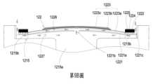
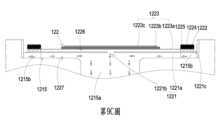
請參閱第12圖所示,上述之過濾清淨組件D可以是多種實施態樣之組合,例如,為一活性碳D1與一高效濾網(High-Efficiency Particulate Air,HEPA)D2所構成,或為一活性碳D1與一高效濾網(High-Efficiency Particulate Air,HEPA)D2及沸石網D3所構成。活性碳D1用以過濾吸附懸浮微粒2.5(PM2.5),沸石網D3用以過濾吸附揮發性有機物(Volatile Organic Compound,VOC),高效濾網D2用以吸附氣體中所含之化學煙霧、細菌、塵埃微粒及花粉,使導入過濾清淨組件D內之氣體汙染,達到過濾淨化之效果。在一些實施例中,高效濾網D2上塗佈一層二氧化氯之潔淨因子,抑制導入過濾清淨組件D之氣體中病毒、細菌、真菌。其中高效濾網D2上可以塗佈一層二氣化氯之潔淨因子,抑制過濾清淨組件D氣體汙染中病毒、細菌、真菌、A型流感病毒、B型流感病毒、腸病毒、諾羅病毒之抑制率達99%以上,幫助少病毒交互傳染。在一些實施例中,高效濾網D2上塗佈一層萃取了銀杏及日本嚴膚木的草本加護塗層,構成一草本加護抗敏濾網,有效抗敏及破壞通過濾網的流感病毒表面蛋白,以及由過濾清淨組件D所導入並通過高效濾網D2之氣體中流感病毒(例如:H1N1)的表面蛋白。另一些實施例中,高效濾網D2上可以塗佈銀離子,抑制所導入氣體中之病毒、細菌、真菌。Please refer to FIG. 12. The above-mentioned filter purification component D can be a combination of various implementation modes, for example, it is composed of an activated carbon D1 and a high-efficiency filter (High-Efficiency Particulate Air, HEPA) D2, or it is composed of an activated carbon D1, a high-efficiency filter (High-Efficiency Particulate Air, HEPA) D2 and a zeolite net D3. The activated carbon D1 is used to filter and adsorb suspended particles 2.5 (PM2.5 ), the zeolite net D3 is used to filter and adsorb volatile organic compounds (Volatile Organic Compound, VOC), and the high-efficiency filter D2 is used to adsorb chemical fumes, bacteria, dust particles and pollen contained in the gas, so that the gas pollution introduced into the filter purification component D can achieve the effect of filtering and purification. In some embodiments, a layer of chlorine dioxide cleaning factor is coated on the high-efficiency filter D2 to inhibit viruses, bacteria, and fungi in the gas introduced into the filter purification component D. Among them, a layer of chlorine dioxide cleaning factor can be coated on the high-efficiency filter D2 to inhibit viruses, bacteria, fungi, influenza A virus, influenza B virus, enterovirus, and norovirus in the gas pollution of the filter purification component D by more than 99%, helping to reduce viral cross-infection. In some embodiments, a layer of herbal protective coating extracted from ginkgo and Japanese ginkgo is coated on the high-efficiency filter D2 to form a herbal protective anti-allergic filter, which effectively fights allergies and destroys the surface protein of influenza virus passing through the filter, as well as the surface protein of influenza virus (e.g., H1N1) in the gas introduced by the filter purification component D and passing through the high-efficiency filter D2. In other embodiments, silver ions can be coated on the high-efficiency filter D2 to inhibit viruses, bacteria, and fungi in the introduced gas.
另一實施例,過濾清淨組件D亦可為活性碳D1、高效濾網D2、沸石網D3搭配光觸媒單元D4所構成之樣態,使室外氣體汙染導入至過濾清淨組件D中,藉由光觸媒單元D4將光能轉化成電能,分解氣體中的有害物質並進行消毒殺菌,以達到過濾及淨化氣體之效果。In another embodiment, the filter purification component D can also be composed of activated carbon D1, high-efficiency filter D2, zeolite filter D3 and photocatalyst unit D4, so that outdoor gas pollution is introduced into the filter purification component D, and the photocatalyst unit D4 converts light energy into electrical energy, decomposes harmful substances in the gas and disinfects and sterilizes, so as to achieve the effect of filtering and purifying the gas.
另一實施例,過濾清淨組件D亦可為活性碳D1、高效濾網D2、沸石網D3搭配光等離子單元D5所構成之樣態,光等離子單元D5包含一奈米光管,透過奈米光管照射過濾清淨組件D所導入之氣體汙染,促使氣體汙染中所含之揮發性有機氣體分解淨化。當過濾清淨組件D將氣體汙染導入,透過奈米光管照射所導入的氣體,使氣體中的氧分子及水分子分解成具高氧化性光等離子,形成具有破壞有機分子的離子氣流,將氣體中含有揮發性甲醛、甲苯、揮發性有機氣體(Volatile Organic Compounds,VOC)等氣體分子分解成水和二氧化碳,達到過濾及淨化氣體之效果。In another embodiment, the filter purification component D may also be composed of activated carbon D1, high-efficiency filter D2, zeolite mesh D3 and photoplasma unit D5. The photoplasma unit D5 includes a nanotube. The nanotube irradiates the gas pollution introduced by the filter purification component D to promote the decomposition and purification of volatile organic gases contained in the gas pollution. When the filter purification component D introduces gas pollution, the nano-light tube irradiates the introduced gas, decomposing the oxygen molecules and water molecules in the gas into highly oxidizing photoplasmas, forming an ion gas flow that destroys organic molecules, decomposing gas molecules containing volatile formaldehyde, toluene, volatile organic compounds (VOCs) and other gas molecules into water and carbon dioxide, achieving the effect of filtering and purifying the gas.
另一實施例,過濾清淨組件D亦可為活性碳D1、高效濾網D2、沸石網D3搭配負離子單元D6所構成之樣態,過濾清淨組件D將室外B所導入的氣體汙染透過經高壓放電,將氣體汙染中所含微粒帶正電荷附著在帶負電荷的進塵板,達到對導入的氣體汙染進行過濾淨化之效果。In another embodiment, the filter purification component D can also be composed of activated carbon D1, high-efficiency filter D2, zeolite filter D3 and negative ion unit D6. The filter purification component D discharges the gas pollution introduced from the outdoor B through high voltage, and attaches the positively charged particles contained in the gas pollution to the negatively charged dust inlet plate, thereby achieving the effect of filtering and purifying the introduced gas pollution.
另一實施例,過濾清淨組件D亦可為活性碳D1、高效濾網D2、沸石網D3搭配電漿離子單元D7所構成之樣態,電漿離子單元D7產生一高壓電漿柱,使高壓電漿柱中電漿離子分解過濾清淨組件D將室外B所導入氣體汙染中的病毒及細菌,且透過電漿離子使得氣體中所含氧分子與水分子電離生成陽離子(H+)和陰離子(O2-),且離子周圍附著有水分子的物質附著在病毒和細菌的表面之後,在化學反應的作用下,會轉化成強氧化性的活性氧(羥,OH基),從而奪走病毒和細菌表面蛋白質的氫,將其氧化分解,以達到過濾導入之氣體進行過濾進化之效果。In another embodiment, the filter purification component D can also be composed of activated carbon D1, high-efficiency filter D2, zeolite filter D3 and plasma ion unit D7. The plasma ion unit D7 generates a high-pressure plasma column, so that the plasma ions in the high-pressure plasma column decompose the viruses and bacteria in the gas pollution introduced by the filter purification component D from the outdoor B, and the oxygen molecules and water molecules contained in the gas are ionized by the plasma ions to generate cations (H+ ) and anions (O2- ), and after the substances with water molecules attached to the ions are attached to the surface of viruses and bacteria, they will be transformed into highly oxidizing active oxygen (hydroxyl, OH group) under the action of chemical reactions, thereby taking away the hydrogen of the surface proteins of viruses and bacteria and oxidizing and decomposing them, so as to achieve the effect of filtering the introduced gas for filtering evolution.
另一實施例,過濾清淨組件D可僅只有高效濾網D2;或是高效濾網D2搭配光觸媒單元D4、光等離子單元D5、負離子單元D6、電漿離子單元D7之任一單元組合;或是高效濾網D2搭配光觸媒單元D4、光等離子單元D5、負離子單元D6及電漿離子單元D7之任二單元之組合;亦或是高效濾網D2搭配光觸媒單元D4、光等離子單元D5、負離子單元D6、電漿離子單元D7之任三單元組合;或是高效濾網D2搭配光觸媒單元D4、光等離子單元D5、負離子單元D6、電漿離子單元D7之所有組合。In another embodiment, the filter purification component D may only have the high-efficiency filter D2; or the high-efficiency filter D2 may be combined with any one of the photocatalyst unit D4, the photoplasma unit D5, the negative ion unit D6, and the plasma ion unit D7; or the high-efficiency filter D2 may be combined with the photocatalyst unit D4, the photoplasma unit D5, the negative ion unit D6, and the plasma ion unit D7. or any combination of high-efficiency filter D2 with photocatalyst unit D4, photoplasma unit D5, negative ion unit D6, and plasma ion unit D7; or any combination of high-efficiency filter D2 with photocatalyst unit D4, photoplasma unit D5, negative ion unit D6, and plasma ion unit D7.
上述空汙源是指懸浮微粒、一氧化碳、二氧化碳、臭氧、二氧化硫、二氧化氮、鉛、總揮發性有機物、甲醛、細菌、真菌、病毒之其中之一或其組合。The above-mentioned air pollution sources refer to one or a combination of suspended particulate matter, carbon monoxide, carbon dioxide, ozone, sulfur dioxide, nitrogen dioxide, lead, total volatile organic matter, formaldehyde, bacteria, fungi, and viruses.
了解本發明之室內空汙防治系統的運作方式後,以下就本發明之氣體偵測模組1之氣體傳輸方式詳細說明。After understanding the operation of the indoor air pollution prevention system of the present invention, the gas transmission method of the
請參閱第3圖至第9A圖所示,氣體偵測模組1包含有:一控制電路板11、一氣體偵測主體12、一微處理器13及一通信器14。其中,氣體偵測主體12、微處理器13及通信器14封裝於控制電路板11形成一體且彼此電性連接。而微處理器13及通信器14設置於控制電路板11上,且微處理器13控制氣體偵測主體12之驅動訊號而啟動偵測運作,並接收氣體偵測主體12所偵測之氣體汙染作數據運算處理,藉由通信器14對外通信,以及將氣體偵測主體12之偵測資料(氣體)轉換成一偵測數據儲存。而通信器14接收微處理器13所輸出之偵測數據(氣體),並將偵測數據傳輸至雲端處理裝置2b或一外部裝置(圖未示),外部裝置可為攜帶式行動裝置(圖未示)。上述的通信器14對外通信傳輸可以是有線之雙向通信傳輸,例如:USB、mini-USB、micro-USB,或者是透過無線之雙向通信傳輸,例如:Wi-Fi模組、藍芽模組、無線射頻辨識模組、近場通訊模組等。Please refer to Figures 3 to 9A, the
而上述氣體偵測主體12包含一基座121、一壓電致動器122、一驅動電路板123,一雷射組件124、一微粒傳感器125、一外蓋126及一氣體傳感器127。其中基座121具有一第一表面1211、一第二表面1212、一雷射設置區1213、一進氣溝槽1214、一導氣組件承載區1215及一出氣溝槽1216。其中第一表面1211與第二表面1212為相對設置之兩個表面。雷射組件124自第一表面1211朝向第二表面1212挖空形成。另,外蓋126罩蓋基座121,並具有一側板1261,側板1261具有一進氣框口1261a與一出氣框口1261b。而進氣溝槽1214自第二表面1212凹陷形成,且鄰近雷射設置區1213。進氣溝槽1214設有一進氣通口1214a,連通於基座121的外部,並與外蓋126的出氣通口1216a對應,以及進氣溝槽1214兩側壁貫穿於壓電致動器122之透光窗口1214b,而與雷射設置區1213連通。因此,基座121的第一表面1211被外蓋126封蓋,第二表面1212被驅動電路板123封蓋,致使進氣溝槽1214定義出一進氣路徑。The
其中,導氣組件承載區1215係由第二表面1212凹陷形成,並連通進氣溝槽1214,且於底面貫通一通氣孔1215a,以及導氣組件承載區1215之四個角分別具有一定位凸塊1215b。而上述之出氣溝槽1216設有一出氣通口1216a,出氣通口1216a與外蓋126的出氣框口1261b對應設置。出氣溝槽1216包含有第一表面1211對於導氣組件承載區1215的垂直投影區域凹陷形成的一第一區間1216b,以及於導氣組件承載區1215的垂直投影區所延伸的區域,且由第一表面1211至第二表面1212挖空形成的第二區間1216c,其中第一區間1216b與第二區間1216c相連以形成段差,且出氣溝槽1216的第一區間1216b與導氣組件承載區1215的通氣孔1215a相通,出氣溝槽1216的第二區間1216c與出氣通口1216a相通。因此,當基座121的第一表面1211被外蓋126封蓋,第二表面1212被驅動電路板123封蓋時,出氣溝槽1216與驅動電路板123共同定義出一出氣路徑。The air guide
再者,上述的雷射組件124及微粒傳感器125皆設置於驅動電路板123上,且位於基座121內,為了明確說明雷射組件124及微粒傳感器125與基座121之位置,故特意省略驅動電路板123,其中雷射組件124容設於基座121的雷射設置區1213內,微粒傳感器125容設於基座121的進氣溝槽1214內,並與雷射組件124對齊。此外,雷射組件124對應到透光窗口1214b,透光窗口1214b供雷射組件124所發射的雷射光穿過,使雷射光照射至進氣溝槽1214。雷射組件124所發出的光束路徑為穿過透光窗口1214b且與進氣溝槽1214形成正交方向。雷射組件124發射光束通過透光窗口1214b進入進氣溝槽1214內,進氣溝槽1214內的氣體中的偵測數據被照射,當光束接觸到氣體內的懸浮微粒時會散射,並產生投射光點,使微粒傳感器125位於其正交方向位置並接收散射所產生的投射光點進行計算,以獲取氣體的偵測數據。另,氣體傳感器127定位設置於驅動電路板123上與其電性連接,且容設於出氣溝槽1216中,供以對導入出氣溝槽1216之氣體汙染做偵測,於本發明一較佳實施例中,氣體傳感器127係為一揮發性有機物傳感器,偵測二氧化碳或總揮發性有機物氣體資訊;或為一甲醛傳感器,偵測甲醛氣體資訊;或為一細菌傳感器,偵測細菌資訊、真菌資訊;或為一病毒傳感器,偵測病毒氣體資訊;或為一溫溼度傳感器,偵測氣體之溫度及濕度資訊。Furthermore, the
以及,上述之壓電致動器122容設於基座121之正方形的導氣組件承載區1215。此外,導氣組件承載區1215與進氣溝槽1214相通,當壓電致動器122作動時,汲取進氣溝槽1214內的氣體進入壓電致動器122,並供氣體通過導氣組件承載區1215的通氣孔1215a,進入出氣溝槽1216。以及,上述的驅動電路板123封蓋於基座121的第二表面1212。雷射組件124設置於驅動電路板123並呈電性連接。微粒傳感器125亦設置於驅動電路板123並呈電性連接。當外蓋126罩於基座121時,出氣通口1216a對應到基座121之進氣通口1214a,出氣框口1261b對應到基座121之出氣通口1216a。And, the
以及,上述壓電致動器122包含一噴氣孔片1221、一腔體框架1222、一致動體1223、一絕緣框架1224及一導電框架1225。其中,噴氣孔片1221為一可繞性材質並具有一懸浮片1221a、一中空孔洞1221b,懸浮片1221a為一彎曲振動之片狀結構,其形狀與尺寸對應導氣組件承載區1215之內緣,而中空孔洞1221b則貫穿懸浮片1221a之中心處,供氣體流通。於本發明較佳實施例中,懸浮片1221a之形狀可為方形、圖形、橢圓形、三角形或多角形其中之一。And, the
以及,上述腔體框架1222疊設於噴氣孔片1221上,且其外觀與噴氣孔片1221對應。致動體1223疊設於腔體框架1222上,並與噴氣孔片1221、懸浮片1221a之間定義出一共振腔室1226。絕緣框架1224疊設於致動體1223上,其外觀與腔體框架1222近似。導電框架1225疊設於絕緣框架1224上,其外觀與絕緣框架1224近似,且導電框架1225具有一導電接腳1225a及自導電接腳1225a外緣向外延伸之一導電電極1225b,且導電電極1225b自導電框架1225內緣向內延伸。Furthermore, the
此外,致動體1223更包含一壓電載板1223a、一調整共振板1223b及一壓電板1223c。其中,壓電載板1223a疊設於腔體框架1222。調整共振板1223b疊設於壓電載板1223a上。壓電板1223c疊設於調整共振板1223b上。而調整共振板1223b及壓電板1223c則容設於絕緣框架1224內。並由導電框架1225之導電電極1225b電連接壓電板1223c。其中,於本發明較佳實施例中,壓電載板1223a與調整共振板1223b皆為導電材料。壓電載板1223a具有一壓電接腳1223d,且壓電接腳1223d與導電接腳1225a連接驅動電路板123上的驅動電路(圖未示),以接收驅動訊號(可為驅動頻率及驅動電壓),驅動訊號得以由壓電接腳1223d、壓電載板1223a、調整共振板1223b、壓電板1223c、導電電極1225b、導電框架1225及導電接腳1225a形成一迴路,並由絕緣框架1224將導電框架1225與致動體1223之間阻隔,避免發生短路現象,使驅動訊號得以傳送至壓電板1223c。壓電板1223c接受驅動訊號後,因壓電效應產生形變,進一步驅動壓電載板1223a及調整共振板1223b產生往復式地彎曲振動。In addition, the
進一步說明,調整共振板1223b位於壓電板1223c與壓電載板1223a之間,作為兩者間的緩衝物,可調整壓電載板1223a的振動頻率。基本上,調整共振板1223b的厚度大於壓電載板1223a,藉由改變調整共振板1223b的厚度調整致動體1223的振動頻率。噴氣孔片1221、腔體框架1222、致動體1223、絕緣框架1224及導電框架1225係依序堆疊設置並定位於導氣組件承載區1215內,促使壓電致動器122定位於導氣組件承載區1215內,壓電致動器122在懸浮片1221a及導氣組件承載區1215的內緣之間定義出一空隙1221c,供氣體流通。To further explain, the tuning
上述之噴氣孔片1221與導氣組件承載區1215之底面間形成一氣流腔室1227。氣流腔室1227透過噴氣孔片1221之中空孔洞1221b連通致動體1223、噴氣孔片1221及懸浮片1221a之間的共振腔室1226,透過共振腔室1226中氣體的振動頻率,使其與懸浮片1221a之振動頻率趨近於相同,可使共振腔室1226與懸浮片1221a產生亥姆霍茲共振效應(Helmholtz resonance),提高氣體的傳輸效率。當壓電板1223c向遠離導氣組件承載區1215之底面移動時,壓電板1223c帶動噴氣孔片1221之懸浮片1221a以遠離導氣組件承載區1215之底面方向移動,使氣流腔室1227之容積急遽擴張,內部壓力下降產生負壓,吸引壓電致動器122外部的氣體由空隙1221c流入,並經由中空孔洞1221b進入共振腔室1226,增加共振腔室1226內的氣壓進而產生一壓力梯度。當壓電板1223c帶動噴氣孔片1221之懸浮片1221a朝向導氣組件承載區1215之底面移動時,共振腔室1226中的氣體經中空孔洞1221b快速流出,擠壓氣流腔室1227內的氣,並使匯聚後的氣體以接近白努利定律之理想氣體狀態快速且大量地噴出導入導氣組件承載區1215的通氣孔1215a。An
透過重覆第9B圖與第9C圖所示的動作,壓電板1223c進行往復式地振動,依據慣性原理,排氣後的共振腔室1226內部氣壓低於平衡氣壓會導引氣體再次進入共振腔室1226中,如此控制共振腔室1226中氣體的振動頻率與壓電板1223c之振動頻率趨於相同,以產生亥姆霍茲共振效應,實現氣體高速且大量的傳輸。By repeating the actions shown in Figure 9B and Figure 9C, the
請再參閱第10A圖至第10C圖所示,氣體皆由外蓋126之進氣通口1214a進入,通過進氣通口1214a進入基座121之進氣溝槽1214,並流至微粒傳感器125的位置。再者,壓電致動器122持續驅動會吸取進氣路徑之氣體,以利外部氣體快速導入且穩定流通,並通過微粒傳感器125上方,此時雷射組件124發射光束通過透光窗口1214b進入進氣溝槽1214,進氣溝槽1214通過微粒傳感器125上方,當微粒傳感器125的光束照射到氣體中的懸浮微粒時會產生散射現象及投射光點,當微粒傳感器125接收散射所產生的投射光點進行計算以獲取氣體中所含的懸浮微粒之粒徑又數量等相關資訊,並且微粒傳感器125上方的氣體也持續受到壓電致動器122驅動而導入導氣組件承載區1215的通氣孔1215a,進入出氣溝槽1216。最後當氣體進入出氣溝槽1216後,由於壓電致動器122不斷輸送氣體進入出氣溝槽1216,因此出氣溝槽1216內的氣體會被推引並通過出氣通口1216a及出氣框口1261b而向外部排出。Please refer to Figures 10A to 10C. The gas enters from the
1a:室外氣體偵測模組1a: Outdoor gas detection module
1b:室內氣體偵測模組1b: Indoor gas detection module
3a:新風機3a: Fresh air blower
31a:進氣通道31a: Intake channel
311a:進氣入口311a: Air intake
312a:進氣出口312a: Air intake outlet
32a:排氣通道32a: Exhaust channel
321a:排氣入口321a: Exhaust inlet
322a:排氣出口322a: Exhaust outlet
33a:循環通道33a: Circulation channel
34a:進氣閥34a: Intake valve
35a:出氣閥35a: Exhaust valve
C:導風機C: Air guide fan
C1:進氣導風機C1: Intake fan
C2:出氣導風機C2: Air outlet fan
D:過濾清淨組件D: Filter and purification components
Claims (54)
Translated fromChinesePriority Applications (5)
| Application Number | Priority Date | Filing Date | Title |
|---|---|---|---|
| TW110115675ATWI839611B (en) | 2021-04-29 | 2021-04-29 | Indoor air pollution prevention system |
| JP2022011267AJP7619972B2 (en) | 2021-04-29 | 2022-01-27 | Indoor Air Pollution Control System |
| CN202210106598.7ACN115264705A (en) | 2021-04-29 | 2022-01-28 | Indoor air pollution prevention and control system |
| US17/586,902US12435890B2 (en) | 2021-04-29 | 2022-01-28 | Indoor air pollution prevention system |
| EP22155849.7AEP4083525A1 (en) | 2021-04-29 | 2022-02-09 | Indoor air pollution prevention system |
Applications Claiming Priority (1)
| Application Number | Priority Date | Filing Date | Title |
|---|---|---|---|
| TW110115675ATWI839611B (en) | 2021-04-29 | 2021-04-29 | Indoor air pollution prevention system |
Publications (2)
| Publication Number | Publication Date |
|---|---|
| TW202242320A TW202242320A (en) | 2022-11-01 |
| TWI839611Btrue TWI839611B (en) | 2024-04-21 |
Family
ID=80447608
Family Applications (1)
| Application Number | Title | Priority Date | Filing Date |
|---|---|---|---|
| TW110115675ATWI839611B (en) | 2021-04-29 | 2021-04-29 | Indoor air pollution prevention system |
Country Status (5)
| Country | Link |
|---|---|
| US (1) | US12435890B2 (en) |
| EP (1) | EP4083525A1 (en) |
| JP (1) | JP7619972B2 (en) |
| CN (1) | CN115264705A (en) |
| TW (1) | TWI839611B (en) |
Families Citing this family (11)
| Publication number | Priority date | Publication date | Assignee | Title |
|---|---|---|---|---|
| TWI858346B (en)* | 2022-06-30 | 2024-10-11 | 研能科技股份有限公司 | Method for detecting, preventing and cleaning indoor air pollution |
| TWI827345B (en)* | 2022-11-07 | 2023-12-21 | 研能科技股份有限公司 | Indoor gas exchange system |
| TWI835399B (en)* | 2022-11-09 | 2024-03-11 | 研能科技股份有限公司 | System for detecting and cleaning indoor air pollution |
| TWI844322B (en)* | 2023-03-29 | 2024-06-01 | 研能科技股份有限公司 | Prevention system for purifying indoor air pollution to close to zero |
| TWI846407B (en)* | 2023-03-29 | 2024-06-21 | 研能科技股份有限公司 | Prevention method of purifying indoor air pollution to close to zero |
| US20240410909A1 (en)* | 2023-06-07 | 2024-12-12 | Kla Corporation | System and method for detecting chemically contaminated samples |
| TW202503205A (en)* | 2023-07-11 | 2025-01-16 | 研能科技股份有限公司 | Indoor air pollution prevention system |
| TW202503206A (en)* | 2023-07-11 | 2025-01-16 | 研能科技股份有限公司 | Indoor air pollution prevention system |
| CN119374178A (en)* | 2023-07-27 | 2025-01-28 | 研能科技股份有限公司 | Indoor air pollution prevention system |
| CN119492107A (en)* | 2023-08-15 | 2025-02-21 | 研能科技股份有限公司 | Air pollution prevention and control system for bathroom space |
| TWI860833B (en)* | 2023-09-06 | 2024-11-01 | 研能科技股份有限公司 | Indoor air cleaning system |
Citations (3)
| Publication number | Priority date | Publication date | Assignee | Title |
|---|---|---|---|---|
| CN105229389A (en)* | 2013-05-13 | 2016-01-06 | 松下知识产权经营株式会社 | ventilation system and control device |
| CN110107952A (en)* | 2019-04-12 | 2019-08-09 | 广州佰伦净化设备制造有限公司 | Internet of Things indoor environment comprehensive treatment device |
| TWI708934B (en)* | 2019-09-27 | 2020-11-01 | 研能科技股份有限公司 | Particle detecting module |
Family Cites Families (33)
| Publication number | Priority date | Publication date | Assignee | Title |
|---|---|---|---|---|
| JP2005149282A (en) | 2003-11-18 | 2005-06-09 | Ixi Co Ltd | Vending machine and server device |
| KR20100019825A (en)* | 2008-08-11 | 2010-02-19 | 웅진코웨이주식회사 | Air cleaner and control method thereof |
| US9517429B2 (en)* | 2012-11-13 | 2016-12-13 | Complete Filter Management Llc | Filtration monitoring system |
| US20150153317A1 (en)* | 2013-11-19 | 2015-06-04 | Acculation, Inc. | System for Inexpensive Characterization of Air Pollutants and Inexpensive Reduction of Indoor Dust |
| JP2015190688A (en) | 2014-03-28 | 2015-11-02 | パナソニックIpマネジメント株式会社 | Ventilation device |
| JP6893668B2 (en) | 2014-08-29 | 2021-06-23 | 株式会社アロマビット | Smell system, odor identification method, odor identification device, portable device, wearable device, air conditioner, and odor information identification program |
| JP6120820B2 (en) | 2014-10-08 | 2017-04-26 | 三菱電機株式会社 | Ventilation system |
| CN104833035A (en)* | 2015-03-18 | 2015-08-12 | 北京金鼎达科技发展有限公司 | Intelligent air purification system and intelligent air purification method |
| US9964481B2 (en)* | 2015-09-04 | 2018-05-08 | Ford Global Technologies, Llc | Method and system for exhaust particulate matter sensing |
| CN105066260B (en)* | 2015-09-07 | 2018-06-22 | 安吉润风空气净化科技有限公司 | A kind of full intelligent air purification device |
| KR20170048789A (en)* | 2015-10-27 | 2017-05-10 | 현대자동차주식회사 | Device for removing dust of vehicle |
| CN105352115A (en) | 2015-10-28 | 2016-02-24 | 北京艾浦乐科技有限公司 | Intelligent air purification system and control method thereof |
| CN107435963B (en) | 2016-05-27 | 2022-10-21 | 宁波方太厨具有限公司 | Integral kitchen structure |
| CN106123160B (en)* | 2016-06-08 | 2023-04-18 | 杭州龙碧科技有限公司 | Variable air volume fresh air equipment |
| EP3521715B1 (en) | 2016-09-29 | 2021-08-25 | Mitsubishi Electric Corporation | Ventilation system |
| US11187419B2 (en) | 2016-12-12 | 2021-11-30 | Pramukha Technologies Pvt. Ltd. | System and method for efficient, ambient air purification |
| CN106931518A (en)* | 2017-04-13 | 2017-07-07 | 张永旺 | A kind of independent Two-way Cycle air cleaning unit and its intelligent control method |
| US11024148B2 (en)* | 2017-05-02 | 2021-06-01 | Johnson Controls Technology Company | Systems and methods for actuator installation auto-verification |
| TWI652652B (en)* | 2017-08-21 | 2019-03-01 | 研能科技股份有限公司 | Apparatus having actuating sensor module within |
| KR101971055B1 (en) | 2017-09-18 | 2019-08-27 | 이재건 | System, method and control device for managing indoor air quality |
| WO2019091987A1 (en) | 2017-11-09 | 2019-05-16 | Koninklijke Philips N.V. | Smart air purification |
| JP6982727B2 (en) | 2017-11-30 | 2021-12-17 | パナソニックIpマネジメント株式会社 | How to control the heat exchange type ventilation fan |
| CN108344113B (en)* | 2018-03-12 | 2024-06-11 | 温州松浦电器有限公司 | Intelligent interconnected air purification system and air purification method |
| CN110609117A (en)* | 2018-06-15 | 2019-12-24 | 研能科技股份有限公司 | Gas detection device |
| CN110812969A (en)* | 2018-08-09 | 2020-02-21 | 陈建荣 | Air cleaning system |
| KR20200031433A (en)* | 2018-09-14 | 2020-03-24 | 남서울대학교 산학협력단 | System for smart purifying indoor air |
| JP2020051658A (en) | 2018-09-26 | 2020-04-02 | パナソニックIpマネジメント株式会社 | Heat exchange type ventilator |
| US20220181031A1 (en) | 2019-01-09 | 2022-06-09 | Koninklijke Philips N.V. | Risk stratification based on infection risk and air pollution exposure |
| JP7460876B2 (en) | 2019-04-22 | 2024-04-03 | ダイキン工業株式会社 | air conditioning system |
| KR102081237B1 (en) | 2019-07-10 | 2020-02-25 | (주)문명에이스 | Ventilation and Energy Saving Air Purifier |
| JPWO2021005736A1 (en) | 2019-07-10 | 2021-09-13 | 三菱電機株式会社 | Air conditioner, particle removal system and control method |
| KR102618721B1 (en) | 2019-08-29 | 2023-12-27 | 엘지전자 주식회사 | Air purifier and operating method of the same |
| JP2021042936A (en) | 2019-09-13 | 2021-03-18 | シャープ株式会社 | Air conditioner |
- 2021
- 2021-04-29TWTW110115675Apatent/TWI839611B/enactive
- 2022
- 2022-01-27JPJP2022011267Apatent/JP7619972B2/enactiveActive
- 2022-01-28USUS17/586,902patent/US12435890B2/enactiveActive
- 2022-01-28CNCN202210106598.7Apatent/CN115264705A/enactivePending
- 2022-02-09EPEP22155849.7Apatent/EP4083525A1/enactivePending
Patent Citations (3)
| Publication number | Priority date | Publication date | Assignee | Title |
|---|---|---|---|---|
| CN105229389A (en)* | 2013-05-13 | 2016-01-06 | 松下知识产权经营株式会社 | ventilation system and control device |
| CN110107952A (en)* | 2019-04-12 | 2019-08-09 | 广州佰伦净化设备制造有限公司 | Internet of Things indoor environment comprehensive treatment device |
| TWI708934B (en)* | 2019-09-27 | 2020-11-01 | 研能科技股份有限公司 | Particle detecting module |
Also Published As
| Publication number | Publication date |
|---|---|
| US12435890B2 (en) | 2025-10-07 |
| JP7619972B2 (en) | 2025-01-22 |
| JP2022171551A (en) | 2022-11-11 |
| TW202242320A (en) | 2022-11-01 |
| CN115264705A (en) | 2022-11-01 |
| US20220349593A1 (en) | 2022-11-03 |
| EP4083525A1 (en) | 2022-11-02 |
Similar Documents
| Publication | Publication Date | Title |
|---|---|---|
| TWI839611B (en) | Indoor air pollution prevention system | |
| TWI778474B (en) | Method of filtering indoor air pollution | |
| TWI834971B (en) | Indoor air pollution prevention system | |
| TWI861464B (en) | Purifier for air pollution prevention | |
| TWI796113B (en) | Exhaust fan for air pollution prevention | |
| TWI872214B (en) | Method of detecting and filtering indoor air pollution | |
| TWI843995B (en) | Air-pollution-preventing fresh air ventilation device | |
| CN114646115A (en) | Intelligent indoor air pollution prevention and control solution | |
| TWI839674B (en) | Vacuum cleaner for air pollution prevention | |
| TWI845887B (en) | Air conditioner for air pollution prevention | |
| TWI806040B (en) | In-car air pollution prevention system | |
| CN115013917A (en) | Indoor gas pollution detection and filtration method | |
| TWI836330B (en) | Fan for air pollution prevention | |
| TWI845888B (en) | Range hood for air pollution prevention | |
| CN114646114A (en) | Intelligent indoor air pollution prevention and control solutions | |
| TWI852473B (en) | Air purifier | |
| TWI837717B (en) | Central controller for indoor air pollution clearance | |
| CN114646126A (en) | Indoor gas pollution filtering method | |
| TWI832148B (en) | Blower for air pollution prevention | |
| TWI818260B (en) | Air pollution prevention device for perambulator | |
| TW202443082A (en) | Range hood | |
| CN118729443A (en) | Indoor air pollution purification and zero prevention and control solutions |