TWI838739B - Automatic system for continuous measurement of electrochemical information - Google Patents
Automatic system for continuous measurement of electrochemical informationDownload PDFInfo
- Publication number
- TWI838739B TWI838739BTW111116287ATW111116287ATWI838739BTW I838739 BTWI838739 BTW I838739BTW 111116287 ATW111116287 ATW 111116287ATW 111116287 ATW111116287 ATW 111116287ATW I838739 BTWI838739 BTW I838739B
- Authority
- TW
- Taiwan
- Prior art keywords
- module
- detection
- unit
- automated system
- circuit board
- Prior art date
Links
- 238000005259measurementMethods0.000titleclaimsabstractdescription9
- 238000001514detection methodMethods0.000claimsabstractdescription100
- 239000007788liquidSubstances0.000claimsabstractdescription52
- 238000005070samplingMethods0.000claimsabstractdescription42
- 238000003860storageMethods0.000claimsabstractdescription42
- 239000007825activation reagentSubstances0.000claimsabstractdescription13
- 238000000835electrochemical detectionMethods0.000claimsabstractdescription8
- 238000012360testing methodMethods0.000claimsdescription48
- 239000012488sample solutionSubstances0.000claimsdescription40
- XLYOFNOQVPJJNP-UHFFFAOYSA-NwaterSubstancesOXLYOFNOQVPJJNP-UHFFFAOYSA-N0.000claimsdescription15
- 238000006073displacement reactionMethods0.000claimsdescription10
- 239000000523sampleSubstances0.000claimsdescription9
- 238000009826distributionMethods0.000claimsdescription4
- 238000003825pressingMethods0.000claimsdescription2
- 238000004519manufacturing processMethods0.000abstractdescription9
- 239000000203mixtureSubstances0.000abstractdescription5
- 238000012544monitoring processMethods0.000abstractdescription5
- 230000000694effectsEffects0.000abstractdescription2
- 238000010586diagramMethods0.000description9
- 239000012085test solutionSubstances0.000description8
- 238000000034methodMethods0.000description7
- 239000000243solutionSubstances0.000description7
- 230000008569processEffects0.000description6
- 239000000126substanceSubstances0.000description5
- 238000006243chemical reactionMethods0.000description4
- 238000011109contaminationMethods0.000description4
- 239000010902strawSubstances0.000description4
- 238000004458analytical methodMethods0.000description3
- 239000000284extractSubstances0.000description3
- 230000003287optical effectEffects0.000description3
- 238000002360preparation methodMethods0.000description3
- 238000004140cleaningMethods0.000description2
- 238000000840electrochemical analysisMethods0.000description2
- 238000000157electrochemical-induced impedance spectroscopyMethods0.000description2
- 238000005516engineering processMethods0.000description2
- 238000002347injectionMethods0.000description2
- 239000007924injectionSubstances0.000description2
- 238000004949mass spectrometryMethods0.000description2
- 238000007781pre-processingMethods0.000description2
- 239000002699waste materialSubstances0.000description2
- 238000004082amperometric methodMethods0.000description1
- 230000008859changeEffects0.000description1
- 238000002484cyclic voltammetryMethods0.000description1
- 230000007547defectEffects0.000description1
- 238000001903differential pulse voltammetryMethods0.000description1
- 239000012895dilutionSubstances0.000description1
- 238000010790dilutionMethods0.000description1
- 238000002848electrochemical methodMethods0.000description1
- 238000007689inspectionMethods0.000description1
- 238000009434installationMethods0.000description1
- 238000004502linear sweep voltammetryMethods0.000description1
- 238000012986modificationMethods0.000description1
- 230000004048modificationEffects0.000description1
- 238000002203pretreatmentMethods0.000description1
- 230000004044responseEffects0.000description1
- 239000004065semiconductorSubstances0.000description1
Images
Landscapes
- Automatic Analysis And Handling Materials Therefor (AREA)
Abstract
Description
Translated fromChinese本發明係關於一種電化學檢測相關技術,尤指一種連續量測電化學資訊的自動化系統。The present invention relates to an electrochemical detection-related technology, and more particularly to an automated system for continuously measuring electrochemical information.
具有化學藥槽的工廠生產過程中,例如半導體製造廠、液晶顯示器面板製造場,一般來說會需監控製程所需之生產槽體內特定化學成分的含量,以確保製程過程的穩定性,確保產出的產品品質,為了避免因為在製程的後端才得知是否有缺陷,導致已產出許多廢品而造成浪費與大規模損失的問題,大多數廠商必須對對生產槽液體進行即時監控以解決所述問題。In the production process of factories with chemical tanks, such as semiconductor manufacturing plants and LCD panel manufacturing plants, it is generally necessary to monitor the content of specific chemical components in the production tank required for the process to ensure the stability of the process and the quality of the output products. In order to avoid the problem of waste and large-scale losses caused by the production of many scrap products due to the defect being known at the end of the process, most manufacturers must monitor the liquid in the production tank in real time to solve the above problem.
生產槽液體的即時監控指標大致上分為溶液溫度、溶液酸鹼度以及溶液導電度三種指標,由於所述指標在針對複雜溶液系統的監控上明顯不足,因此工廠多會成立化學分析實驗室,對槽內溶液定期進行化驗。The real-time monitoring indicators of the production tank liquid are generally divided into three types: solution temperature, solution pH, and solution conductivity. Since the above indicators are obviously insufficient for monitoring complex solution systems, factories often set up chemical analysis laboratories to conduct regular tests on the solutions in the tank.
分析實驗室設備多以光學或質譜分析監測技術為主,而光學以及質譜分析方法必須先經過複雜的前處理,將待測溶液處理為較單純的狀態後,才能夠上機分析,在檢測結果的取得上耗費許多時間,難以立即得知生產槽液體的變化。Most analytical laboratory equipment is based on optical or mass spectrometry analysis and monitoring technology. Optical and mass spectrometry analysis methods must first undergo complex pre-treatment to treat the solution to be tested in a simpler state before analysis can be performed on the machine. It takes a lot of time to obtain the test results, and it is difficult to immediately know the changes in the production tank liquid.
本發明主要目的在於提供一種連續量測電化學資訊的自動化系統,能夠連續且快速的取得製程所需溶液之檢測結果,以達到更佳的即時監控之效果。The main purpose of the present invention is to provide an automated system for continuously measuring electrochemical information, which can continuously and quickly obtain the test results of the solution required for the process, so as to achieve a better real-time monitoring effect.
為達上述目的,本發明之一項實施例提供一種連續量測電化學資訊的自動化系統,其包含一儲存模組、一混和模組、一陣列電路板、一操控模組以及一電化學模組;儲存模組具有一容置空間,容置空間用以暫存一樣品溶液;混和模組設置位置相異於儲存模組;陣列電路板設置位置相異於儲存模組以及混和模組,陣列電路板包括複數獨立檢測區,各獨立檢測區具有一量測部以及一電極單元;操控模組具有一取樣單元以及一檢測連接單元,取樣單元能夠在儲存模組、混和模組以及陣列電路板之間來回移動,以將樣品溶液注入混和模組,使樣品溶液與一活化試劑混和以形成一待測液,取樣單元將待測液注入其中一獨立檢測區之量測部,檢測連接單元能夠移動至對應有待測液的獨立檢測區,並與獨立檢測區的電極單元進行電性連接;電化學模組耦接操控模組,電化學模組能夠對待測液進行電化學檢測,以取得待測液之檢測資訊。To achieve the above-mentioned object, an embodiment of the present invention provides an automated system for continuously measuring electrochemical information, which includes a storage module, a mixing module, an array circuit board, a control module and an electrochemical module; the storage module has a storage space, and the storage space is used to temporarily store a sample solution; the mixing module is set at a different position from the storage module; the array circuit board is set at a different position from the storage module and the mixing module, and the array circuit board includes a plurality of independent detection areas, each of which has a measurement portion and an electrode unit; the control module has a sampling unit and a detection connection unit. The sampling unit can move back and forth between the storage module, the mixing module and the array circuit board to inject the sample solution into the mixing module, so that the sample solution is mixed with an activation reagent to form a test liquid. The sampling unit injects the test liquid into the measuring part of one of the independent detection areas. The detection connection unit can move to the independent detection area corresponding to the test liquid and electrically connect with the electrode unit of the independent detection area. The electrochemical module is coupled to the control module, and the electrochemical module can perform electrochemical detection on the test liquid to obtain detection information of the test liquid.
藉此,本發明之自動化系統,透過包括有複數獨立檢測區的陣列電路板,配合能夠在儲存模組、混和模組以及陣列電路板之間來回移動的操控模組,能夠在不需複雜的前處理步驟的情況下,對待測液進行連續的分析,且能節省清洗容器以及電極所需的時間,有效提升電化學分析的速率,而能夠對待測液進行即時監控,進而達到更佳的製程良率控制。Thus, the automated system of the present invention, through an array circuit board including a plurality of independent detection areas, cooperates with a control module that can move back and forth between a storage module, a mixing module and the array circuit board, can continuously analyze the test liquid without complicated pre-processing steps, and can save the time required for cleaning containers and electrodes, effectively improve the rate of electrochemical analysis, and can monitor the test liquid in real time, thereby achieving better process yield control.
為便於說明本發明於上述發明內容一欄中所表示的中心思想,茲以具體實施例表達。實施例中各種不同物件係按適於說明之比例、尺寸、變形量或位移量而描繪,而非按實際元件的比例予以繪製,合先敘明。In order to facilitate the description of the central idea of the present invention in the above invention content column, specific embodiments are used for illustration. Various objects in the embodiments are depicted according to the proportions, sizes, deformations or displacements suitable for the description, rather than being drawn according to the proportions of the actual components, which should be noted in advance.
請參閱圖1至圖10所示,本發明提供一種連續量測電化學資訊的自動化系統100,圖1係本發明自動化系統100之方塊連結示意圖;圖2係本發明自動化系統100之外觀示意圖。Please refer to FIG. 1 to FIG. 10 , the present invention provides an automated system 100 for continuously measuring electrochemical information. FIG. 1 is a block connection diagram of the automated system 100 of the present invention; FIG. 2 is an external view of the automated system 100 of the present invention.
自動化系統100包含一儲存模組10、一混和模組20、一陣列電路板30、一檢測平台40、一操控模組50、一電化學模組60、一第一偵測模組70、一第二偵測模組80;其中,儲存模組10連結至一工作槽1,混和模組20設置位置相異於儲存模組10,陣列電路板30設於檢測平台40,且設置位置相異於儲存模組10以及混和模組20,電化學模組60、第一偵測模組70以及第二偵測模組80耦接操控模組50。The automated system 100 includes a storage module 10, a mixing module 20, an array circuit board 30, a detection platform 40, a control module 50, an electrochemical module 60, a first detection module 70, and a second detection module 80; wherein the storage module 10 is connected to a working tank 1, the mixing module 20 is arranged at a position different from the storage module 10, the array circuit board 30 is arranged on the detection platform 40, and is arranged at a position different from the storage module 10 and the mixing module 20, and the electrochemical module 60, the first detection module 70, and the second detection module 80 are coupled to the control module 50.
儲存模組10具有一容置空間11、一樣品進入口12、一進水口13以及一排放口14,一樣品進入口12、一進水口13以及一排放口14連通容置空間11;其中,容置空間11用以暫存一樣品溶液2,樣品進入口12用以使樣品溶液2流入容置空間11,進水口13用以使一清水流入容置空間11,排放口14用以排空容置空間11內的液體。The storage module 10 has a accommodating space 11, a sample inlet 12, a water inlet 13 and a discharge port 14, wherein the sample inlet 12, the water inlet 13 and the discharge port 14 are connected to the accommodating space 11; wherein the accommodating space 11 is used to temporarily store a sample solution 2, the sample inlet 12 is used to allow the sample solution 2 to flow into the accommodating space 11, the water inlet 13 is used to allow clean water to flow into the accommodating space 11, and the discharge port 14 is used to drain the liquid in the accommodating space 11.
儲存模組10利用幫浦收集工作槽1內欲分析的樣品溶液2,於本實施例中,容置空間11可分隔為不同隔間,以同時自不同工作槽1收集不同的樣品溶液2。The storage module 10 uses a pump to collect the sample solution 2 to be analyzed in the working tank 1. In this embodiment, the accommodating space 11 can be divided into different compartments to collect different sample solutions 2 from different working tanks 1 at the same time.
儲存模組10若欲更換待分析的樣品溶液2,需要對容置空間11進行清洗,以避免前次樣品溶液2所造成的汙染,儲存模組10能夠利用排放口14排空容置空間11內之樣品溶液2,並以重複利用進水口13引入清水以及利用排放口14排空清水的方式,清洗容置空間11。If the storage module 10 is to replace the sample solution 2 to be analyzed, the storage space 11 needs to be cleaned to avoid contamination caused by the previous sample solution 2. The storage module 10 can use the discharge port 14 to drain the sample solution 2 in the storage space 11, and repeatedly use the water inlet 13 to introduce clean water and use the discharge port 14 to drain the clean water to clean the storage space 11.
於本實施例中,儲存模組10每間隔一取樣時間利用樣品進入口12自工作槽1引入樣品溶液2,藉此可隨時檢測工作槽1內的化學液體濃度,以維持工作槽1內化學液體的濃度恆定。In this embodiment, the storage module 10 uses the sample inlet 12 to introduce the sample solution 2 from the working tank 1 at every sampling time, thereby detecting the concentration of the chemical liquid in the working tank 1 at any time to maintain the concentration of the chemical liquid in the working tank 1 constant.
陣列電路板30包括複數獨立檢測區31,如圖4所示,各獨立檢測區31具有一量測部311以及一電極單元312,量測部311經由導線(圖中未示)連結至電極單元312;於本實施例中,量測部311以及電極單元312之間具有一最短距離d,最短距離d小於0.5公分,以縮減獨立檢測區31之長度,而避免陣列電路板30佔用過大的面積。The array circuit board 30 includes a plurality of independent detection areas 31. As shown in FIG. 4 , each independent detection area 31 has a measuring portion 311 and an electrode unit 312. The measuring portion 311 is connected to the electrode unit 312 via a wire (not shown). In this embodiment, there is a shortest distance d between the measuring portion 311 and the electrode unit 312. The shortest distance d is less than 0.5 cm to reduce the length of the independent detection area 31 and prevent the array circuit board 30 from occupying too large an area.
量測部311包含一工作電極3111、一對電極3112以及一參考電極3113,電極單元312為3個電極接點3121,各電極分別連接至一電極接點3121,其中,量測部311內之工作電極3111、對電極3112以及參考電極3113可設計為不同構造(如圖4所示),以因應不同的樣品溶液2而進行不同的電化學量測。The measuring part 311 includes a working electrode 3111, a pair of electrodes 3112 and a reference electrode 3113. The electrode unit 312 is three electrode contacts 3121, and each electrode is connected to an electrode contact 3121. The working electrode 3111, the pair of electrodes 3112 and the reference electrode 3113 in the measuring part 311 can be designed into different structures (as shown in FIG. 4) to perform different electrochemical measurements in response to different sample solutions 2.
如圖3至4所示,檢測平台40具有一定位部41,陣列電路板30之周緣更具有一防呆部32,防呆部32能夠用以辨別不同檢測用途之陣列電路板30,以及供定位部41穿伸以將陣列電路板30定位於檢測平台40。以圖4舉例來說,左邊的陣列電路板30a右邊僅有三個防呆部32可供定位部41定位設置;而右邊的陣列電路板30b右邊有四個防呆部32可供定位部41定位設置,藉此使用者於置放時便不會搞錯置放的位置,避免錯置問題的發生。As shown in FIGS. 3 and 4 , the testing platform 40 has a positioning portion 41, and the periphery of the array circuit board 30 further has a foolproof portion 32, which can be used to distinguish array circuit boards 30 for different testing purposes, and for the positioning portion 41 to extend through so as to position the array circuit board 30 on the testing platform 40. Taking FIG. 4 as an example, the left array circuit board 30a has only three foolproof portions 32 on the right side for the positioning portion 41 to position and set; while the right array circuit board 30b has four foolproof portions 32 on the right side for the positioning portion 41 to position and set, so that the user will not make a mistake in the placement when placing it, thus avoiding the occurrence of the wrong placement problem.
操控模組50具有一取樣單元51、一檢測連接單元52以及一位移控制單元53,其中,取樣單元51及檢測連接單元52設於位移控制單元53。The control module 50 has a sampling unit 51 , a detection connection unit 52 and a displacement control unit 53 , wherein the sampling unit 51 and the detection connection unit 52 are disposed in the displacement control unit 53 .
取樣單元51能夠在儲存模組10、混和模組20以及陣列電路板30之間來回移動,以將樣品溶液2注入混和模組20,使樣品溶液2與一活化試劑混和以形成一待測液3,接著將待測液3注入陣列電路板30其中一獨立檢測區31之量測部311。The sampling unit 51 can move back and forth between the storage module 10, the mixing module 20 and the array circuit board 30 to inject the sample solution 2 into the mixing module 20, mix the sample solution 2 with an activation reagent to form a test liquid 3, and then inject the test liquid 3 into the measuring part 311 of one of the independent detection areas 31 of the array circuit board 30.
進一步說明,樣品溶液2以及活化試劑需先在混和模組20中進行如稀釋、化學反應、變更酸鹼度或增加導電度等反應,接著才將反應完成而形成的待測液3注入獨立檢測區31之量測部311,藉以避免反應過程對量測部311表面造成汙染,而影響到後續量測。To further explain, the sample solution 2 and the activation reagent must first undergo reactions such as dilution, chemical reaction, change of pH or increase of conductivity in the mixing module 20, and then the test solution 3 formed after the reaction is injected into the measuring part 311 of the independent detection area 31 to avoid contamination of the surface of the measuring part 311 during the reaction process, thereby affecting subsequent measurements.
此外,取樣單元51能夠在每一次將待測液3注入陣列電路板30時,配合各獨立檢測區31的排列位置而移動,依序將待測液3注入不同的獨立檢測區31。In addition, each time the sampler unit 51 injects the test liquid 3 into the array circuit board 30 , it can move in accordance with the arrangement positions of the independent detection areas 31 , and sequentially inject the test liquid 3 into different independent detection areas 31 .
取樣單元51具有一定量吸管組511,定量吸管組511能夠抽取及釋放液體,定量吸管組511分為一第一定量吸管5111以及一第二定量吸管5112,第一定量吸管5111用以自儲存模組10抽取樣品溶液2,並將樣品溶液2注入混和模組20,第二定量吸管5112用以將待測液3注入獨立檢測區31之量測部311。The sampling unit 51 has a certain amount of pipette set 511. The quantitative pipette set 511 can extract and release liquid. The quantitative pipette set 511 is divided into a first quantitative pipette 5111 and a second quantitative pipette 5112. The first quantitative pipette 5111 is used to extract the sample solution 2 from the storage module 10 and inject the sample solution 2 into the mixing module 20. The second quantitative pipette 5112 is used to inject the test liquid 3 into the measuring part 311 of the independent detection area 31.
其中,第二定量吸管5112更能夠用以混和樣品溶液2以及活化試劑,取樣單元51能夠重複按壓第二定量吸管5112,利用抽吸方式以混和樣品溶液2以及活化試劑而形成待測液3。The second quantitative pipette 5112 can be used to mix the sample solution 2 and the activation reagent. The sampling unit 51 can repeatedly press the second quantitative pipette 5112 to mix the sample solution 2 and the activation reagent by suction to form the test solution 3.
於本實施例中,第一定量吸管5111與第二定量吸管5112所吸取的容量不相同,第一定量吸管5111之容量約為2至20µL,第二定量吸管5112之容量則為20至200µL,第二定量吸管5112以較大的容量抽吸混和樣品溶液2以及活化試劑,能夠令所形成之待測液3較為均勻。In this embodiment, the volumes sucked by the first quantitative pipette 5111 and the second quantitative pipette 5112 are different. The capacity of the first quantitative pipette 5111 is approximately 2 to 20µL, and the capacity of the second quantitative pipette 5112 is 20 to 200µL. The second quantitative pipette 5112 sucks the mixed sample solution 2 and the activation reagent with a larger capacity, which can make the formed test solution 3 more uniform.
第二定量吸管5112在將待測液3注入獨立檢測區31之量測部311後,取樣單元51能夠控制一吸管尖4以水平方向繞圈方式接觸位於量測部311的待測液3,以使待測液3均勻分布佈滿於量測部311而形成電化學檢測迴路,以利於後續檢測。After the second quantitative pipette 5112 injects the test liquid 3 into the measuring part 311 of the independent detection area 31, the sampling unit 51 can control a pipette tip 4 to contact the test liquid 3 in the measuring part 311 in a horizontal circular manner, so that the test liquid 3 is evenly distributed in the measuring part 311 to form an electrochemical detection circuit, which is convenient for subsequent detection.
檢測連接單元52能夠移動至對應有待測液3的獨立檢測區31並與所述獨立檢測區31的電極單元312進行電性連接。The detection connection unit 52 can be moved to the independent detection area 31 corresponding to the test liquid 3 and electrically connected to the electrode unit 312 of the independent detection area 31.
於本實施例中,檢測連接單元52具有一檢測頂針521以及一彈性件522,彈性件522設於檢測頂針521之垂直上方,檢測頂針521用以接觸電極單元312,彈性件522用以在檢測連接單元52透過檢測頂針521接觸電極單元312時增加緩衝,避免檢測頂針521在垂直方向移動而加壓至接觸電極單元312時過於壓迫,而損壞到接觸電極單元312的問題;除此之外亦可以透過下壓力道的緩衝調整,增加檢測頂針521與接觸電極單元312的接觸面積,進一步避免阻抗過大的問題。In this embodiment, the detection connection unit 52 has a detection pin 521 and an elastic member 522. The elastic member 522 is disposed vertically above the detection pin 521. The detection pin 521 is used to contact the electrode unit 312. The elastic member 522 is used to increase the detection connection unit 52 when the detection pin 521 contacts the electrode unit 312. The buffer is added to avoid the problem that the detection pin 521 is over-pressed when it moves in the vertical direction and pressurizes the contact electrode unit 312, thereby damaging the contact electrode unit 312. In addition, the contact area between the detection pin 521 and the contact electrode unit 312 can be increased by adjusting the buffer of the downward pressure, thereby further avoiding the problem of excessive impedance.
檢測頂針521為3個針體5211,針體5211能夠分別接觸3個電極接點3121以與量測部311之工作電極3111、對電極3112以及參考電極3113導通。The detection top needle 521 is composed of three needle bodies 5211, and the needle bodies 5211 can contact three electrode contacts 3121 respectively to conduct with the working electrode 3111, the counter electrode 3112 and the reference electrode 3113 of the measuring part 311.
於本實施例中,位移控制單元53具有一供取樣單元51設置的第一移動臂531以及一供檢測連接單元52設置的第二移動臂532,而使取樣單元51及檢測連接單元52獨立進行移動,藉此加速電化學檢測的進行。In this embodiment, the displacement control unit 53 has a first moving arm 531 for the sampling unit 51 and a second moving arm 532 for the detection connection unit 52, so that the sampling unit 51 and the detection connection unit 52 can move independently, thereby accelerating the electrochemical detection.
在其他實施例中,取樣單元51以及檢測連接單元52亦可共同設置於位移控制單元53上而同步進行移動。In other embodiments, the sampling unit 51 and the detection connection unit 52 may also be disposed together on the displacement control unit 53 and move synchronously.
電化學模組60能夠在檢測連接單元52電連接電極單元312後,對待測液3進行電化學檢測,以取得待測液3之檢測資訊,藉此即時確認工作槽1內樣品溶液2的狀況,以便進行工作槽1樣品溶液2的管理。舉例來說,可以使用循環伏安法(Cyclic Voltammetry, CV)、線性掃描伏安法(Linear Sweep Voltammetry, LSV)、脈衝伏安法(Differential Pulse Voltammetry,DPV)、安培法(Amperometry ,IT)或電化學阻抗頻譜法(Electrochemical Impedance Spectroscopy,EIS)等分析方法。After the detection connection unit 52 is electrically connected to the electrode unit 312, the electrochemical module 60 can perform electrochemical detection on the test solution 3 to obtain detection information of the test solution 3, thereby instantly confirming the status of the sample solution 2 in the working tank 1, so as to manage the sample solution 2 in the working tank 1. For example, analysis methods such as cyclic voltammetry (CV), linear sweep voltammetry (LSV), differential pulse voltammetry (DPV), amperometry (IT) or electrochemical impedance spectroscopy (EIS) can be used.
第一偵測模組70用以確認吸管尖4裝配至定量吸管組511,取樣單元51在透過定量吸管組511吸取液體之前,能夠在定量吸管組511上裝套吸管尖4,並移動至第一偵測模組70而確認吸管尖4確實套於定量吸管組511;於本實施例中,第一偵測模組70為紅外線感測器。The first detection module 70 is used to confirm that the pipette tip 4 is assembled to the quantitative pipette set 511. Before the sampling unit 51 absorbs the liquid through the quantitative pipette set 511, it can put the pipette tip 4 on the quantitative pipette set 511 and move to the first detection module 70 to confirm that the pipette tip 4 is indeed put on the quantitative pipette set 511. In this embodiment, the first detection module 70 is an infrared sensor.
第二偵測模組80用以進行待測液3於量測部311的分佈確認,以確保待測液3均勻分布於量測部311,以利於後續電化學檢測;於本實施例中,第二偵測模組80為攝影機,而可透過自動光學檢查(Automated Optical Inspection, AOI)進行待測液3的分布確認。The second detection module 80 is used to confirm the distribution of the test liquid 3 in the measuring part 311 to ensure that the test liquid 3 is evenly distributed in the measuring part 311, so as to facilitate subsequent electrochemical testing. In this embodiment, the second detection module 80 is a camera, and the distribution of the test liquid 3 can be confirmed by automated optical inspection (AOI).
於本實施例中,更進一步包括一震動模組90,震動模組90連接混和模組20,震動模組90能夠利用震盪或搖晃混和模組20之方式以混和樣品溶液2與一活化試劑。In this embodiment, a shaking module 90 is further included. The shaking module 90 is connected to the mixing module 20. The shaking module 90 can mix the sample solution 2 and an activation reagent by shaking or rocking the mixing module 20.
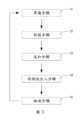
上述內容,為說明本發明所提供一種連續量測電化學資訊的自動化系統100之一具體實施例,以下進一步說明自動化系統100之自動化檢測方法,如圖5所示,係本發明自動化系統100之量測步驟流程圖。The above content is to illustrate a specific embodiment of an automated system 100 for continuously measuring electrochemical information provided by the present invention. The automated detection method of the automated system 100 is further described below. As shown in FIG. 5 , it is a flow chart of the measurement steps of the automated system 100 of the present invention.
一準備步驟S1:將樣品溶液2由工作槽1引入至儲存模組10之容置空間11,將活化試劑注入混和模組20,以及將陣列電路板30放置於檢測平台40。其中,可以將多個不同工作槽1與該儲存模組10以連通管連接,避免人工取樣的麻煩與不便。更進一步的,不同工作槽1可以連接至儲存模組10的相同容置空間11,而在不同時間取樣;或者也可以連接至儲存模組10中不同的容置空間11,而避免樣品溶液2混雜污染的問題。進一步的,可透過儲存模組10所具有之進水口13以及排放口14進行該容置空間11的清洗,避免不同樣品溶液2之間的污染。A preparation step S1: Introduce the sample solution 2 from the working tank 1 into the containing space 11 of the storage module 10, inject the activation reagent into the mixing module 20, and place the array circuit board 30 on the detection platform 40. Among them, multiple different working tanks 1 can be connected to the storage module 10 with a connecting tube to avoid the trouble and inconvenience of manual sampling. Furthermore, different working tanks 1 can be connected to the same containing space 11 of the storage module 10 and sampled at different times; or they can also be connected to different containing spaces 11 in the storage module 10 to avoid the problem of mixed contamination of the sample solution 2. Furthermore, the containing space 11 can be cleaned through the water inlet 13 and the discharge port 14 of the storage module 10 to avoid contamination between different sample solutions 2.
一取樣步驟S2:在取樣單元51之第一定量吸管5111上裝套吸管尖4,並藉由第一偵測模組70確認第一定量吸管5111上吸管尖4的裝配,取樣單元51接著移動至容置空間11抽取樣品溶液2(如圖6所示),並將樣品溶液2注入混和模組20(如圖7所示),接著將第一定量吸管5111上之吸管尖4丟棄。A sampling step S2: The pipette tip 4 is mounted on the first quantitative pipette 5111 of the sampling unit 51, and the assembly of the pipette tip 4 on the first quantitative pipette 5111 is confirmed by the first detection module 70. The sampling unit 51 is then moved to the accommodating space 11 to extract the sample solution 2 (as shown in FIG. 6 ), and the sample solution 2 is injected into the mixing module 20 (as shown in FIG. 7 ), and then the pipette tip 4 on the first quantitative pipette 5111 is discarded.
一混和步驟S3:在取樣單元51之第二定量吸管5112上裝套吸管尖4,並藉由第一偵測模組70確認第二定量吸管5112上吸管尖4的裝配,接著以取樣單元51重複按壓第二定量吸管5112的抽吸方式,或是藉由震動模組90震盪或搖晃混和模組20的方式,將樣品溶液2與活化試劑進行混和以形成待測液3。A mixing step S3: a pipette tip 4 is mounted on the second quantitative pipette 5112 of the sampling unit 51, and the installation of the pipette tip 4 on the second quantitative pipette 5112 is confirmed by the first detection module 70, and then the sample solution 2 is mixed with the activation reagent to form a test solution 3 by repeatedly pressing the second quantitative pipette 5112 with the sampling unit 51, or by vibrating or shaking the mixing module 20 with the vibration module 90.
一待測液注入步驟S4:取樣單元51藉由第二定量吸管5112抽取待測液3,並移動至陣列電路板30,將待測液3注入其中一獨立檢測區31之量測部311(如圖8所示),取樣單元51控制第二定量吸管5112之吸管尖4以水平方向繞圈方式接觸位於量測部311的待測液3,以使待測液3均勻分布於量測部311,並藉由第二偵測模組80進行待測液3於量測部311的分佈確認,接著取樣單元51將第二定量吸管5112上之吸管尖4丟棄。A test liquid injection step S4: the sampling unit 51 extracts the test liquid 3 through the second quantitative pipette 5112 and moves it to the array circuit board 30 to inject the test liquid 3 into the measuring part 311 of one of the independent detection areas 31 (as shown in FIG. 8 ). The sampling unit 51 controls the pipette tip 4 of the second quantitative pipette 5112 to contact the test liquid 3 in the measuring part 311 in a horizontal circular manner so that the test liquid 3 is evenly distributed in the measuring part 311, and the distribution of the test liquid 3 in the measuring part 311 is confirmed by the second detection module 80. Then the sampling unit 51 discards the pipette tip 4 on the second quantitative pipette 5112.
一檢測步驟S5:將檢測連接單元52移動至對應有待測液3的獨立檢測區31並與所述獨立檢測區31的電極單元312進行電性連接(如圖9至圖10所示),接著透過電化學模組60對待測液3進行電化學檢測,以取得待測液3之檢測資訊,並回到準備步驟S1,依此循環直到陣列電路板30上所有的獨立檢測區31檢測完畢,將檢測完成之廢液與陣列電路板30移除。A detection step S5: the detection connection unit 52 is moved to the independent detection area 31 corresponding to the test liquid 3 and electrically connected to the electrode unit 312 of the independent detection area 31 (as shown in Figures 9 to 10), and then the test liquid 3 is electrochemically detected by the electrochemical module 60 to obtain the detection information of the test liquid 3, and then return to the preparation step S1, and the cycle is repeated until all the independent detection areas 31 on the array circuit board 30 are detected, and the waste liquid and the array circuit board 30 after the detection are removed.
綜合上述,本發明之自動化系統100,透過包括有複數獨立檢測區31的陣列電路板30,配合能夠在儲存模組10、混和模組20以及陣列電路板30之間來回移動的操控模組50,能夠在不需複雜的前處理步驟的情況下,對待測液3進行連續的分析,且能節省習知電化學檢測清洗容器以及電極所需的時間,有效提升電化學分析的速率,而能夠對待測液3進行即時監控,進而達到更佳的製程良率控制。In summary, the automated system 100 of the present invention, through an array circuit board 30 including a plurality of independent detection areas 31, cooperates with a control module 50 capable of moving back and forth between a storage module 10, a mixing module 20 and the array circuit board 30, can continuously analyze the test liquid 3 without complicated pre-processing steps, and can save the time required for cleaning containers and electrodes for electrochemical detection, effectively improve the rate of electrochemical analysis, and can monitor the test liquid 3 in real time, thereby achieving better process yield control.
以上所舉實施例僅用以說明本發明而已,非用以限制本發明之範圍。舉凡不違本發明精神所從事的種種修改或變化,俱屬本發明意欲保護之範疇。The above embodiments are only used to illustrate the present invention and are not used to limit the scope of the present invention. Any modifications or changes that do not violate the spirit of the present invention are within the scope of protection of the present invention.
1:工作槽 2:樣品溶液 3:待測液 4:吸管尖 100:自動化系統 10:儲存模組 11:容置空間 12:樣品進入口 13:進水口 14:排放口 20:混和模組 30:陣列電路板 30a:陣列電路板 30b:陣列電路板 31:獨立檢測區 311:量測部 3111:工作電極 3112:對電極 3113:參考電極 312:電極單元 3121:電極接點 32:防呆部 40:檢測平台 41:定位部 50:操控模組 51:取樣單元 511:定量吸管組 5111:第一定量吸管 5112:第二定量吸管 52:檢測連接單元 521:檢測頂針 5211:針體 522:彈性件 53:位移控制單元 531:第一移動臂 532:第二移動臂 60:電化學模組 70:第一偵測模組 80:第二偵測模組 90:震動模組 d:最短距離 S1:準備步驟 S2:取樣步驟 S3:混和步驟 S4:待測液注入步驟 S5:檢測步驟1: working tank 2: sample solution3: test solution 4: pipette tip100: automation system 10: storage module11: storage space 12: sample inlet13: water inlet 14: discharge port20: mixing module 30: array circuit board30a: array circuit board 30b: array circuit board31: independent detection area 311: measurement unit3111: working electrode 3112: counter electrode3113: reference electrode 312: electrode unit3121: electrode contact 32: foolproof unit40: detection platform 41: positioning unit50: control module 51: sampling unit511: quantitative pipette set 5111: First quantitative pipette5112: Second quantitative pipette 52: Detection connection unit521: Detection needle 5211: Needle body522: Elastic member 53: Displacement control unit531: First moving arm 532: Second moving arm60: Electrochemical module 70: First detection module80: Second detection module 90: Vibration moduled: Shortest distance S1: Preparation stepS2: Sampling step S3: Mixing stepS4: Test liquid injection step S5: Detection step
圖1係本發明自動化系統之方塊連結示意圖。 圖2係本發明連自動化系統之外觀示意圖。 圖3係本發明陣列電路板放置於檢測平台之示意圖。 圖4本發明陣列電路板之示意圖。 圖5係本發明自動化系統之量測步驟流程圖。 圖6係本發明實施狀態示意圖(一),用於表示取樣單元抽取樣品溶液。 圖7係本發明實施狀態示意圖(二),用於表示取樣單元將樣品溶液注入混和模組。 圖8係本發明實施狀態示意圖(三),用於表示取樣單元將待測液注入獨立檢測區。 圖9係本發明實施狀態示意圖(四),用於表示檢測連接單元與電極單元進行電性連接。 圖10係本發明圖9之局部放大圖。Figure 1 is a schematic diagram of the block connection of the automation system of the present invention.Figure 2 is a schematic diagram of the appearance of the automation system of the present invention.Figure 3 is a schematic diagram of the array circuit board of the present invention placed on the detection platform.Figure 4 is a schematic diagram of the array circuit board of the present invention.Figure 5 is a flow chart of the measurement steps of the automation system of the present invention.Figure 6 is a schematic diagram of the implementation state of the present invention (I), which is used to show that the sampling unit extracts the sample solution.Figure 7 is a schematic diagram of the implementation state of the present invention (II), which is used to show that the sampling unit injects the sample solution into the mixing module.Figure 8 is a schematic diagram of the implementation state of the present invention (III), which is used to show that the sampling unit injects the test solution into the independent detection area.Figure 9 is a schematic diagram of the implementation state of the present invention (IV), which is used to show that the detection connection unit and the electrode unit are electrically connected.Figure 10 is a partial enlarged view of Figure 9 of the present invention.
4:吸管尖4: Tip of the straw
10:儲存模組10: Storage module
11:容置空間11: Storage space
20:混和模組20: Mixed module
30:陣列電路板30: Array circuit board
40:檢測平台40: Testing platform
50:操控模組50: Control module
51:取樣單元51: Sampling unit
511:定量吸管組511: Quantitative straw set
5111:第一定量吸管5111: The first quantitative straw
5112:第二定量吸管5112: Second quantitative straw
52:檢測連接單元52: Detection connection unit
521:檢測頂針521: Testing the thimble
522:彈性件522: Elastic parts
53:位移控制單元53: Displacement control unit
531:第一移動臂531: First moving arm
532:第二移動臂532: Second mobile arm
70:第一偵測模組70: First detection module
80:第二偵測模組80: Second detection module
90:震動模組90: Vibration module
Claims (14)
Translated fromChinesePriority Applications (1)
| Application Number | Priority Date | Filing Date | Title |
|---|---|---|---|
| TW111116287ATWI838739B (en) | 2022-04-28 | 2022-04-28 | Automatic system for continuous measurement of electrochemical information |
Applications Claiming Priority (1)
| Application Number | Priority Date | Filing Date | Title |
|---|---|---|---|
| TW111116287ATWI838739B (en) | 2022-04-28 | 2022-04-28 | Automatic system for continuous measurement of electrochemical information |
Publications (2)
| Publication Number | Publication Date |
|---|---|
| TW202342975A TW202342975A (en) | 2023-11-01 |
| TWI838739Btrue TWI838739B (en) | 2024-04-11 |
Family
ID=89720557
Family Applications (1)
| Application Number | Title | Priority Date | Filing Date |
|---|---|---|---|
| TW111116287ATWI838739B (en) | 2022-04-28 | 2022-04-28 | Automatic system for continuous measurement of electrochemical information |
Country Status (1)
| Country | Link |
|---|---|
| TW (1) | TWI838739B (en) |
Citations (5)
| Publication number | Priority date | Publication date | Assignee | Title |
|---|---|---|---|---|
| US20030070917A1 (en)* | 2001-10-11 | 2003-04-17 | Symyx Technologies, Inc. | Synthesis and characterization of materials for electrochemical cells |
| US20080210573A1 (en)* | 2003-12-15 | 2008-09-04 | Geneohm Sciences, Inc. | Multiplexed electrochemical detection system and method |
| CN107085118A (en)* | 2010-10-29 | 2017-08-22 | 恩姆菲舍尔科技公司 | Automated systems and methods for sample preparation and analysis |
| CN109709349A (en)* | 2019-03-07 | 2019-05-03 | 南京迪格诺斯生物技术有限公司 | A kind of chemiluminescence immunoassay system |
| CN110702767A (en)* | 2018-07-10 | 2020-01-17 | 佳能医疗系统株式会社 | Automatic analysis device |
- 2022
- 2022-04-28TWTW111116287Apatent/TWI838739B/enactive
Patent Citations (5)
| Publication number | Priority date | Publication date | Assignee | Title |
|---|---|---|---|---|
| US20030070917A1 (en)* | 2001-10-11 | 2003-04-17 | Symyx Technologies, Inc. | Synthesis and characterization of materials for electrochemical cells |
| US20080210573A1 (en)* | 2003-12-15 | 2008-09-04 | Geneohm Sciences, Inc. | Multiplexed electrochemical detection system and method |
| CN107085118A (en)* | 2010-10-29 | 2017-08-22 | 恩姆菲舍尔科技公司 | Automated systems and methods for sample preparation and analysis |
| CN110702767A (en)* | 2018-07-10 | 2020-01-17 | 佳能医疗系统株式会社 | Automatic analysis device |
| CN109709349A (en)* | 2019-03-07 | 2019-05-03 | 南京迪格诺斯生物技术有限公司 | A kind of chemiluminescence immunoassay system |
Also Published As
| Publication number | Publication date |
|---|---|
| TW202342975A (en) | 2023-11-01 |
Similar Documents
| Publication | Publication Date | Title |
|---|---|---|
| US20210208033A1 (en) | Diffusive gradients in thin films (dgt) test device for lake water and test method using same | |
| CN106153964A (en) | A kind of electrolyte analyser and the automatically method of sampling | |
| CN108195998A (en) | A kind of laboratory COD automatically analyzes robot | |
| EP2612154B1 (en) | Pressure monitoring of whole blood aspirations to determine completeness of whole blood mixing | |
| US20140134051A1 (en) | Automated platelet function analyzer and its analytical methods | |
| CN112834772B (en) | Device and method for measuring trace elements | |
| CN111141810B (en) | Capillary electrophoresis apparatus for water environment on-site monitoring and use method thereof | |
| WO2011034170A1 (en) | Ion selective electrode cartridge | |
| WO2011034168A1 (en) | Ion selective electrode cartridge | |
| CN202120107U (en) | Automatic quality control system for water quality on-line monitoring | |
| CN113330316A (en) | Automated sample and standard preparation based on identifying sample identity and sample type | |
| TWI838739B (en) | Automatic system for continuous measurement of electrochemical information | |
| KR20170122147A (en) | Syringe assembly and method of using the same | |
| CN117554313B (en) | Automatic detection system and automatic detection method | |
| CN219201627U (en) | Automatic analysis system for formaldehyde content in textile | |
| CN116698935B (en) | PH sensor verifying attachment | |
| CN103412130A (en) | Reagent cup assembly, instrument and method for quickly determining content of specific proteins of urine | |
| CN207946437U (en) | A kind of fox protein analysis device | |
| CN112185842A (en) | Liquid injection device, semiconductor detection system and detection method thereof | |
| CN114199976A (en) | Potassium ion concentration sensor based on impedance analysis, detection device and method | |
| JPH0484770A (en) | Analyzer line control method | |
| CN216870384U (en) | Basic-level full-automatic body fluid inspection platform and automatic body fluid analysis system | |
| JPH0213959Y2 (en) | ||
| CN112285188A (en) | Application method of tubular suction nozzle type electrochemical sensing device | |
| CN112748062A (en) | Device and method for detecting hydrogen-induced cracking resistance of metal material |