TWI838244B - Gripper mechanism of robot arm for packaging and method thereof - Google Patents
Gripper mechanism of robot arm for packaging and method thereofDownload PDFInfo
- Publication number
- TWI838244B TWI838244BTW112117166ATW112117166ATWI838244BTW I838244 BTWI838244 BTW I838244BTW 112117166 ATW112117166 ATW 112117166ATW 112117166 ATW112117166 ATW 112117166ATW I838244 BTWI838244 BTW I838244B
- Authority
- TW
- Taiwan
- Prior art keywords
- packaging
- suction cup
- stepper motor
- drive
- machine arm
- Prior art date
Links
Images


Landscapes
- Supplying Of Containers To The Packaging Station (AREA)
Abstract
Description
Translated fromChinese本發明係有關於一種包裝用機器手臂夾爪機構及其方法,尤其是指一種自動化將包裝袋展開,且將待包裝物裝入包裝袋內之作業,不僅可大幅減少人力成本的支出,且能加速包裝作業流程,並能降低發生錯誤的機率,進而具有廣大的市場潛力,而在其整體施行使用上更增實用功效特性者。The present invention relates to a packaging machine arm gripper mechanism and method thereof, and in particular to an automated operation of unfolding a packaging bag and placing the object to be packaged into the packaging bag, which can not only significantly reduce labor costs, but also speed up the packaging process and reduce the probability of errors, thus having broad market potential and increasing practical efficacy characteristics in its overall implementation and use.
按,近年來隨著網路發達、科技技術的進步,使得電子商務產業迅速發展且帶動線上購物的商機,人們透過網路購物也越來越為便利,也因此令人們的消費習慣也隨之改變;另,於忙碌的現代社會中,人們由於忙於課業、工作等,大多沒有時間料理三餐,使得各式的餐飲業蓬勃發展,人們越來越依賴外食解決各餐。According to the report, in recent years, with the development of the Internet and the advancement of science and technology, the e-commerce industry has developed rapidly and brought about business opportunities for online shopping. It has become more and more convenient for people to shop online, and people's consumption habits have also changed accordingly. In addition, in the busy modern society, most people do not have time to prepare three meals a day due to being busy with schoolwork and work, which has led to the booming development of various catering industries, and people are increasingly relying on eating out to solve their meals.
而不論係為電子商務產業或餐飲業等,其皆需要有大量的人力資源進行各項服務,如:商品包裝;然,也因為現今人力資源的短缺,造成人力成本大幅增加,加上人工作業較為緩慢、容易發生錯誤,導致相關業者皆致力於自動化作業的研發。Whether it is the e-commerce industry or the catering industry, it requires a large amount of human resources to perform various services, such as product packaging; however, due to the current shortage of human resources, labor costs have increased significantly. In addition, manual operations are slow and prone to errors, resulting in related industries all devoting themselves to the research and development of automated operations.
緣是,發明人有鑑於此,秉持多年該相關行業之豐富設計開發及實際製作經驗,針對現有之結構及缺失再予以研究改良,提供一種包裝用機器手臂夾爪機構及其方法,以期達到更佳實用價值性之目的者。Therefore, the inventor, in view of this, has adhered to the rich design development and actual manufacturing experience in the relevant industry for many years, and has further studied and improved the existing structure and defects, and provided a packaging machine arm clamp mechanism and method, in order to achieve the purpose of better practical value.
本發明之主要目的在於提供一種包裝用機器手臂夾爪機構及其方法,主要係利用夾爪裝置搭配吸盤裝置及指型裝置之設置,達到自動化將包裝袋展開,且將待包裝物裝入包裝袋內之作業,不僅可大幅減少人力成本的支出,且能加速包裝作業流程,並能降低發生錯誤的機率,進而具有廣大的市場潛力,而在其整體施行使用上更增實用功效特性者。The main purpose of the present invention is to provide a packaging machine arm gripper mechanism and method thereof, which mainly utilizes the gripper device in combination with the suction cup device and the finger device to achieve the automatic unfolding of the packaging bag and the loading of the object to be packaged into the packaging bag. It can not only greatly reduce the expenditure of labor costs, but also speed up the packaging process and reduce the probability of errors, thus having broad market potential and increasing the practical and functional characteristics in its overall implementation and use.
1:控制主機1: Control host
11:控制器11: Controller
12:步進馬達驅動單元12: Stepper motor drive unit
13:電動吸盤幫浦13: Electric suction cup pump
14:伺服馬達14:Servo motor
15:機器手臂驅動單元15: Robot arm drive unit
151:機器手臂151: Robotic Arm
16:步進馬達16: Stepper Motor
2:夾爪裝置2: Gripping device
21:夾爪座21: Clamping claw seat
22:傳動蝸桿22: Transmission snail
23:爪部23: Claws
24:傳動齒輪24: Drive gear
25:止滑軟墊25: Anti-slip soft pad
251:定位溝槽251: Positioning groove
3:吸盤裝置3: Suction cup device
4:指型裝置4: Finger-type device
41:定位座41: Positioning seat
42:壓指部42: Pressing finger parts
43:連動單元43: Linkage unit
5:包裝袋5: Packaging bag
51:袋口51: Bag opening
6:工作平臺6: Work platform
7:待包裝物7: Objects to be packaged
第一圖:本發明之整體機構方塊示意圖Figure 1: Schematic diagram of the overall mechanism block of the present invention
第二圖:第二圖本發明之結構示意圖(一)Figure 2: Figure 2 is a schematic diagram of the structure of the present invention (I)
第三圖:本發明之結構示意圖(二)Figure 3: Schematic diagram of the structure of the present invention (II)
第四圖:本創作之局部立體結構示意圖Figure 4: Schematic diagram of the partial three-dimensional structure of this creation
第五圖:本創作之局部俯視剖視結構示意圖Figure 5: A partial top-down cross-sectional structural diagram of this work
第六圖:本發明之使用包裝動作示意圖(一)Figure 6: Schematic diagram of the packaging action of the present invention (I)
第七圖:本發明之使用包裝動作示意圖(二)Figure 7: Schematic diagram of the packaging action of the present invention (II)
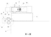
第八圖:本發明之使用包裝動作示意圖(三)Figure 8: Schematic diagram of the packaging action of the present invention (III)
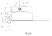
第九圖:本發明之使用包裝動作示意圖(四)Figure 9: Schematic diagram of the packaging action of the present invention (IV)
第十圖:本發明之使用包裝動作示意圖(五)Figure 10: Schematic diagram of the packaging action of the present invention (V)
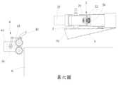
第十一圖:本發明之使用包裝動作示意圖(六)Figure 11: Schematic diagram of the packaging action of the present invention (VI)
第十二圖:本發明之使用包裝動作示意圖(七)Figure 12: Schematic diagram of the packaging action of the present invention (VII)
第十三圖:本發明之夾爪裝置使用狀態剖視結構示意圖Figure 13: Schematic diagram of the cross-sectional structure of the clamping device of the present invention in use
第十四圖:本發明之使用包裝動作示意圖(八)Figure 14: Schematic diagram of the packaging action of the present invention (VIII)
為令本發明所運用之技術內容、發明目的及其達成之功效有更完整且清楚的揭露,茲於下詳細說明之,並請一併參閱所揭之圖式及圖號:首先,請參閱第一圖本發明之整體機構方塊示意圖、第二圖本發明之結構示意圖(一)、第三圖本發明之結構示意圖(二)、第四圖本創作之局部立體結構示意圖及第五圖本創作之局部俯視剖視結構示意圖所示,本發明主要係包括有控制主機(1)、夾爪裝置(2)、吸盤裝置(3)及指型裝置(4);其中:該控制主機(1),其設有控制器(11),於該控制器(11)分別連接有步進馬達驅動單元(12)、電動吸盤幫浦(13)、伺服馬達(14)及機器手臂驅動單元(15),且於該步進馬達驅動單元(12)連接有步進馬達(16),該步進馬達驅動單元(12)供驅動該步進馬達(16)進行作動,該電動吸盤幫浦(13)供產生負壓吸力,該伺服馬達(14)則係依照內建指令進行作動,而該機器手臂驅動單元(15)則供驅動機器手臂(151)進行動作。In order to make the technical content, purpose of the invention and the effect achieved by the present invention more complete and clear, they are described in detail below, and please refer to the disclosed drawings and figure numbers: First, please refer to the first figure of the overall mechanism block diagram of the present invention, the second figure of the structure diagram (I) of the present invention, the third figure of the structure diagram (II) of the present invention, the fourth figure of the partial three-dimensional structure diagram of the present invention and the fifth figure of the partial top view cross-sectional structure diagram of the present invention. As shown in FIG, the present invention mainly includes a control host (1), a gripper device (2), a suction cup device (3) and a finger device (4); wherein: the control host (1) ), which is provided with a controller (11), and the controller (11) is respectively connected to a stepper motor drive unit (12), an electric suction cup pump (13), a servo motor (14) and a machine arm drive unit (15), and the stepper motor drive unit (12) is connected to a stepper motor (16), the stepper motor drive unit (12) is used to drive the stepper motor (16) to perform an action, the electric suction cup pump (13) is used to generate a negative pressure suction force, the servo motor (14) is actuated according to a built-in instruction, and the machine arm drive unit (15) is used to drive the machine arm (151) to perform an action.
該夾爪裝置(2),其設有夾爪座(21),令該控制主機(1)之該步進馬達(16)設置於該夾爪座(21),且令該夾爪座(21)受該機器手臂(151)帶動進行動作,於該步進馬達(16)的輸出端連接設有傳動蝸桿(22),於該夾爪座(21)樞設有兩相對應之爪部(23),於兩該爪部(23)內側端皆與傳動齒輪(24)相連接,而兩該傳動齒輪(24)則與該傳動蝸桿(22)相嚙合,使得該步進馬達(16)作動時能帶動該傳動蝸桿(22)進行轉動,令該傳動蝸桿(22)同步帶動兩該傳動齒輪(24)轉動,而讓兩該爪部(23)隨著兩該傳動齒輪(24)的轉動進行夾、放動作,另於兩該爪部(23)內側端面設置有止滑軟墊(25),該止滑軟墊(25)內側並凹設有定位溝槽(251)。The clamping device (2) is provided with a clamping seat (21), and the stepping motor (16) of the control host (1) is arranged on the clamping seat (21), and the clamping seat (21) is driven by the machine arm (151) to move. The output end of the stepping motor (16) is connected to a transmission screw rod (22), and the clamping seat (21) is provided with two corresponding claws (23), and the inner side ends of the two claws (23) are connected to the transmission gear (24), and the two transmission gears are connected to the transmission gear (24). The wheel (24) is engaged with the transmission snail (22), so that the stepper motor (16) can drive the transmission snail (22) to rotate when it is actuated, so that the transmission snail (22) synchronously drives the two transmission gears (24) to rotate, and the two claws (23) perform clamping and releasing actions along with the rotation of the two transmission gears (24). In addition, a non-slip soft pad (25) is provided on the inner side end surface of the two claws (23), and a positioning groove (251) is recessed on the inner side of the non-slip soft pad (25).
該吸盤裝置(3),其組設固定於該夾爪裝置(2)之該夾爪座(21)處,令該吸盤裝置(3)與該控制主機(1)之該電動吸盤幫浦(13)相連接,使得於該電動吸盤幫浦(13)產生負壓吸力時,能透過該吸盤裝置(3)吸附物品。The suction cup device (3) is fixedly mounted on the clamping claw seat (21) of the clamping claw device (2), so that the suction cup device (3) is connected to the electric suction cup pump (13) of the control host (1), so that when the electric suction cup pump (13) generates negative pressure suction, the object can be sucked through the suction cup device (3).
該指型裝置(4),其設有定位座(41),令該控制主機(1)之該伺服馬達(14)設置於該定位座(41)內,於該定位座(41)樞設有壓指部(42),該壓指部(42)連結於連動單元(43)之一端,而該連動單元(43)另一端則與該伺服馬達(14)相連結,使得該伺服馬達(14)作動時能透過該連動單元(43)帶動該壓指部(42)作動。The finger-type device (4) is provided with a positioning seat (41), so that the servo motor (14) of the control host (1) is arranged in the positioning seat (41), and a pressing finger (42) is centrally arranged on the positioning seat (41). The pressing finger (42) is connected to one end of a linkage unit (43), and the other end of the linkage unit (43) is connected to the servo motor (14), so that when the servo motor (14) is actuated, the pressing finger (42) can be driven to actuate through the linkage unit (43).
如此一來,使得本發明在操作使用上具有下列步驟:A.令控制主機(1)之控制器(11)控制機器手臂驅動單元(15)驅動機器手臂(151)進行動作,以利用該機器手臂(151)將夾爪裝置(2)之夾爪座(21)移動至包裝袋(5)上,令該夾爪座(21)上所設置之吸盤裝置(3)貼靠於該包裝袋(5);B.令該控制器(11)控制電動吸盤幫浦(13)產生負壓吸力,以透過與該電動吸盤幫浦(13)連接之該吸盤裝置(3)將該包裝袋(5)吸起〔請再一併參閱第六圖本發明之使用包裝動作示意圖(一)所示〕;C.令該夾爪座(21)帶動被吸附在該吸盤裝置(3)之該包裝袋(5)往指型裝置(4)移動,此時該包裝袋(5)之袋口(51)會因重力往下略為打開,讓該包裝袋(5)移動至該指型裝置(4)之壓指部(42)伸入該袋口(51)內〔請再一併參閱第七圖本發明之使用包裝動作示意圖(二)所示〕;D.令該控制器(11)控制伺服馬達(14)作動,讓該伺服馬達(14)透過連動單元(43)帶動壓指部(42)將一側之該袋口(51)壓掣在工作平臺(6)上,同時令該夾爪座(21)向上升起,而使該包裝袋(5)之該袋口(51)完全打開〔請再一併參閱第八圖本發明之使用包裝動作示意圖(三)所示〕;E.令該控制器(11)控制該伺服馬達(14)作動,讓該伺服馬達(14)透過該連動單元(43)帶動該壓指部(42)上升,放開對該袋口(51)之壓掣〔請再一併參閱第九圖本發明之使用包裝動作示意圖(四)所示〕;F.令該夾爪座(21)轉動方向,帶動被吸附在該吸盤裝置(3)之該包裝袋(5)直立於該工作平臺(6)上〔請再一併參閱第十圖本發明之使用包裝動作示意圖(五)所示〕,再令該控制器(11)控制停止該電動吸盤幫浦(13)作動,以讓該吸盤裝置(3)放開對該包裝袋(5)之吸附;G.令該夾爪座(21)移動至所欲進行包裝之待包裝物(7)處〔請再一併參閱第十一圖本發明之使用包裝動作示意圖(六)所示〕;H.令該控制器(11)控制步進馬達驅動單元(12)驅動步進馬達(16)進行作動,使得該步進馬達(16)帶動傳動蝸桿(22)進行轉動,令該傳動蝸桿(22)同步帶動兩傳動齒輪(24)轉動,而讓分別與兩該傳動齒輪(24)連接之兩爪部(23)隨之將該待包裝物(7)夾起〔請再一併參閱第十二圖本發明之使用包裝動作示意圖(七)所示〕,此時由於兩該爪部(23)內側端面設置有止滑軟墊(25),且該止滑軟墊(25)內側凹設有該定位溝槽(251),使得能方便夾持為矩形、圓形〔請再一併參閱第十三圖本發明之夾爪裝置使用狀態剖視結構示意圖所示〕、或菱形等各式形狀之該待包裝物(7),利用該止滑軟墊(25)搭配該定位溝槽(251)能防止該待包裝物(7)滑動、轉動,而讓該待包裝物(7)穩固夾持定位不脫落;I:令該夾爪座(21)帶動該待包裝物(7)由該袋口(51)處移至該包裝袋(5)內〔請再一併參閱第十四圖本發明之使用包裝動作示意圖(八)所示〕,令該控制器(11)控制該步進馬達驅動單元(12)驅動該步進馬達(16)進行作動,使得兩該爪部(23)放開對該待包裝物(7)之夾持,令該夾爪座(21)移動離開該包裝袋(5),即完成該待包裝物(7)之包裝作業。Thus, the present invention has the following steps in operation: A. the controller (11) of the control host (1) controls the machine arm driving unit (15) to drive the machine arm (151) to move, so as to use the machine arm (151) to move the clamping claw seat (21) of the clamping claw device (2) onto the packaging bag (5), so that the suction cup device (3) provided on the clamping claw seat (21) is attached to the packaging bag (5); B. the controller (11) controls the electric suction cup pump (13) Generate negative pressure suction to suck up the packaging bag (5) through the suction cup device (3) connected to the electric suction cup pump (13) [please refer to the sixth figure of the present invention for the schematic diagram of the packaging operation (I)]; C. Make the clamping claw seat (21) drive the packaging bag (5) adsorbed on the suction cup device (3) to move toward the finger device (4), at which time the bag mouth (51) of the packaging bag (5) will open slightly downward due to gravity, allowing the packaging bag (5) to move to the pressure finger of the finger device (4). D. the controller (11) controls the servo motor (14) to operate, so that the servo motor (14) drives the pressing finger (42) through the linkage unit (43) to press the bag opening (51) on one side onto the working platform (6), and at the same time, the clamping claw seat (21) rises upward, so that the bag opening (51) of the packaging bag (5) is completely opened (please refer to FIG. [0046] as shown in the eighth figure of the present invention in the packaging operation diagram (iii)]; E. the controller (11) controls the servo motor (14) to operate, so that the servo motor (14) drives the pressing finger (42) to rise through the linkage unit (43) and releases the pressure on the bag opening (51) [please also refer to the ninth figure of the present invention in the packaging operation diagram (iv)]; F. the claw seat (21) is rotated to drive the packaging bag (5) adsorbed on the suction cup device (3) to stand upright on the bag opening (51) The working platform (6) is placed on the working platform (6) (please refer to the schematic diagram (5) of the packaging operation of the present invention in the tenth figure) and the controller (11) is controlled to stop the electric suction cup pump (13) so that the suction cup device (3) releases the suction of the packaging bag (5); G. The clamping claw seat (21) is moved to the packaging object (7) to be packaged (please refer to the schematic diagram (6) of the packaging operation of the present invention in the eleventh figure)); H. The controller (11) is controlled to control the stepping motor The drive unit (12) drives the stepper motor (16) to operate, so that the stepper motor (16) drives the transmission worm (22) to rotate, so that the transmission worm (22) synchronously drives the two transmission gears (24) to rotate, and the two claws (23) connected to the two transmission gears (24) respectively clamp the object to be packaged (7) [please refer to the schematic diagram of the packaging operation of the present invention in Figure 12 (VII)]. At this time, since the inner side end surfaces of the two claws (23) are provided with anti-slip soft The non-slip soft pad (25) is provided with a positioning groove (251) on the inner side thereof, so that the object to be packaged (7) in various shapes such as rectangular, circular (please refer to the schematic diagram of the structure of the clamping claw device of the present invention in the 13th figure for the cross-sectional view of the clamping claw device in the use state as shown in the figure) or rhombus can be conveniently clamped. The non-slip soft pad (25) and the positioning groove (251) can prevent the object to be packaged (7) from sliding or rotating, so that the object to be packaged (7) can be firmly clamped and positioned without falling off; I: The clamping claw seat ( 21) drives the object to be packaged (7) from the bag opening (51) to move into the packaging bag (5) [please refer to the schematic diagram (eight) of the packaging operation of the present invention in Figure 14], and the controller (11) controls the stepper motor driving unit (12) to drive the stepper motor (16) to operate, so that the two claws (23) release the clamping of the object to be packaged (7), and the clamping claw seat (21) moves away from the packaging bag (5), thus completing the packaging operation of the object to be packaged (7).
藉由以上所述,本發明之使用實施說明可知,本發明與現有技術手段相較之下,本發明主要係利用夾爪裝置搭配吸盤裝置及指型裝置之設置,達到自動化將包裝袋展開,且將待包裝物裝入包裝袋內之作業,不僅可大幅減少人力成本的支出,且能加速包裝作業流程,並能降低發生錯誤的機率,進而具有廣大的市場潛力,而在其整體施行使用上更增實用功效特性者。From the above, it can be seen from the implementation description of the present invention that compared with the existing technical means, the present invention mainly utilizes the clamping claw device in combination with the suction cup device and the finger device to achieve the automatic operation of unfolding the packaging bag and putting the packaged object into the packaging bag, which can not only greatly reduce the expenditure of labor costs, but also speed up the packaging operation process and reduce the probability of errors, thus having broad market potential and increasing the practical efficacy characteristics in its overall implementation and use.
然而前述之實施例或圖式並非限定本發明之產品結構或使用方式,任何所屬技術領域中具有通常知識者之適當變化或修飾,皆應視為不脫離本發明之專利範疇。However, the aforementioned embodiments or drawings do not limit the product structure or usage of the present invention. Any appropriate changes or modifications by those with ordinary knowledge in the relevant technical field should be considered as not departing from the patent scope of the present invention.
綜上所述,本發明實施例確能達到所預期之使用功效,又其所揭露之具體構造,不僅未曾見諸於同類產品中,亦未曾公開於申請前,誠已完全符合專利法之規定與要求,爰依法提出發明專利之申請,懇請惠予審查,並賜准專利,則實感德便。In summary, the embodiments of the present invention can achieve the expected effects, and the specific structure disclosed is not only not seen in similar products, but also has not been disclosed before the application. It fully complies with the provisions and requirements of the Patent Law. Therefore, an application for invention patent is filed in accordance with the law. I sincerely request your review and grant of patent. I would really appreciate the convenience.
1:控制主機1: Control host
11:控制器11: Controller
12:步進馬達驅動單元12: Stepper motor drive unit
13:電動吸盤幫浦13: Electric suction cup pump
14:伺服馬達14:Servo motor
15:機器手臂驅動單元15: Robot arm drive unit
151:機器手臂151: Robotic Arm
16:步進馬達16: Stepper Motor
23:爪部23: Claws
3:吸盤裝置3: Suction cup device
42:壓指部42: Pressing finger parts
Claims (10)
Translated fromChinesePriority Applications (1)
| Application Number | Priority Date | Filing Date | Title |
|---|---|---|---|
| TW112117166ATWI838244B (en) | 2023-05-09 | 2023-05-09 | Gripper mechanism of robot arm for packaging and method thereof |
Applications Claiming Priority (1)
| Application Number | Priority Date | Filing Date | Title |
|---|---|---|---|
| TW112117166ATWI838244B (en) | 2023-05-09 | 2023-05-09 | Gripper mechanism of robot arm for packaging and method thereof |
Publications (2)
| Publication Number | Publication Date |
|---|---|
| TWI838244Btrue TWI838244B (en) | 2024-04-01 |
| TW202444614A TW202444614A (en) | 2024-11-16 |
Family
ID=91618489
Family Applications (1)
| Application Number | Title | Priority Date | Filing Date |
|---|---|---|---|
| TW112117166ATWI838244B (en) | 2023-05-09 | 2023-05-09 | Gripper mechanism of robot arm for packaging and method thereof |
Country Status (1)
| Country | Link |
|---|---|
| TW (1) | TWI838244B (en) |
Citations (5)
| Publication number | Priority date | Publication date | Assignee | Title |
|---|---|---|---|---|
| WO1988005403A1 (en)* | 1987-01-20 | 1988-07-28 | Sica Du Silo De La Rochelle-Pallice | Method and device for taking one by one bags from a pile of bags and for placing them in a predetermined position |
| US7134256B2 (en)* | 2003-08-01 | 2006-11-14 | Furukawa Mfg. Co., Ltd. | Packaging system |
| TW201714789A (en)* | 2015-10-23 | 2017-05-01 | 財團法人工業技術研究院 | Automatic packaging machine and packaging method using the same |
| CN211943953U (en)* | 2019-12-27 | 2020-11-17 | 山东海利莱化工科技有限公司 | Vacuum chuck type bag opening mechanism |
| CN115571418A (en)* | 2022-10-20 | 2023-01-06 | 重庆果智林智能科技有限公司 | Fruit bag opening device |
- 2023
- 2023-05-09TWTW112117166Apatent/TWI838244B/enactive
Patent Citations (5)
| Publication number | Priority date | Publication date | Assignee | Title |
|---|---|---|---|---|
| WO1988005403A1 (en)* | 1987-01-20 | 1988-07-28 | Sica Du Silo De La Rochelle-Pallice | Method and device for taking one by one bags from a pile of bags and for placing them in a predetermined position |
| US7134256B2 (en)* | 2003-08-01 | 2006-11-14 | Furukawa Mfg. Co., Ltd. | Packaging system |
| TW201714789A (en)* | 2015-10-23 | 2017-05-01 | 財團法人工業技術研究院 | Automatic packaging machine and packaging method using the same |
| CN211943953U (en)* | 2019-12-27 | 2020-11-17 | 山东海利莱化工科技有限公司 | Vacuum chuck type bag opening mechanism |
| CN115571418A (en)* | 2022-10-20 | 2023-01-06 | 重庆果智林智能科技有限公司 | Fruit bag opening device |
Also Published As
| Publication number | Publication date |
|---|---|
| TW202444614A (en) | 2024-11-16 |
Similar Documents
| Publication | Publication Date | Title |
|---|---|---|
| CN106184924B (en) | A kind of length finger fold cross glue seals formula paper box packing machine | |
| CN203005811U (en) | Mechanism for fully automatically sticking protective film and screwing material head | |
| CN111975354A (en) | Fingertip gyroscope assembling device | |
| CN206427316U (en) | Portable special-shaped fragile article automatic film covering packing machine | |
| CN204760432U (en) | Solid brilliant machine of encapsulation LED | |
| CN105857741B (en) | Carton packing machine | |
| CN104369897A (en) | Automatic film sticking device | |
| CN108188877B (en) | An integrated mold grinding device | |
| CN206742198U (en) | A semiconductor cover laminating machine | |
| TWI838244B (en) | Gripper mechanism of robot arm for packaging and method thereof | |
| CN204772536U (en) | Modified sign indicating number brick manipulator | |
| CN211685856U (en) | Packing carton mechanism of unpacking | |
| CN219729708U (en) | Finished product packaging stacking grabbing device | |
| CN109231808B (en) | Scoring mechanism and scoring method for manufacturing ampoules | |
| CN107127109B (en) | A kind of sticker pearl all-in-one machine | |
| CN206579936U (en) | Automatic manual dispenser | |
| WO2018214551A1 (en) | Adhesive dispensing and bead pasting integrated machine with card transfer device | |
| WO2014121429A1 (en) | Full-automatic device for filling and encapsulating packing bag | |
| CN101530997B (en) | Double pick-and-place arm die bonding mechanism | |
| CN114261556A (en) | PLC (programmable logic controller) controlled bottle cap sealing process | |
| CN110802832A (en) | Full-automatic high-speed servo numerical control plastic suction forming machine | |
| CN221938661U (en) | Positioning mechanism of tail sealing machine | |
| CN1326685C (en) | Assembly machine for disposable plastic transfusion bottle | |
| CN114603588B (en) | A kind of ceramic cup clamping and turning manipulator | |
| CN221641948U (en) | An arbitrary angle zipper bag making and trimming device |