TWI835246B - Microphone system and beamforming method - Google Patents
Microphone system and beamforming methodDownload PDFInfo
- Publication number
- TWI835246B TWI835246BTW111130904ATW111130904ATWI835246BTW I835246 BTWI835246 BTW I835246BTW 111130904 ATW111130904 ATW 111130904ATW 111130904 ATW111130904 ATW 111130904ATW I835246 BTWI835246 BTW I835246B
- Authority
- TW
- Taiwan
- Prior art keywords
- sound sources
- electronic device
- microphone
- sensor
- microphones
- Prior art date
Links
Images


Classifications
- G—PHYSICS
- G06—COMPUTING OR CALCULATING; COUNTING
- G06N—COMPUTING ARRANGEMENTS BASED ON SPECIFIC COMPUTATIONAL MODELS
- G06N3/00—Computing arrangements based on biological models
- G06N3/02—Neural networks
- G06N3/08—Learning methods
- G06N3/084—Backpropagation, e.g. using gradient descent
- H—ELECTRICITY
- H04—ELECTRIC COMMUNICATION TECHNIQUE
- H04R—LOUDSPEAKERS, MICROPHONES, GRAMOPHONE PICK-UPS OR LIKE ACOUSTIC ELECTROMECHANICAL TRANSDUCERS; DEAF-AID SETS; PUBLIC ADDRESS SYSTEMS
- H04R1/00—Details of transducers, loudspeakers or microphones
- H04R1/20—Arrangements for obtaining desired frequency or directional characteristics
- H04R1/32—Arrangements for obtaining desired frequency or directional characteristics for obtaining desired directional characteristic only
- H04R1/40—Arrangements for obtaining desired frequency or directional characteristics for obtaining desired directional characteristic only by combining a number of identical transducers
- H04R1/406—Arrangements for obtaining desired frequency or directional characteristics for obtaining desired directional characteristic only by combining a number of identical transducers microphones
- G—PHYSICS
- G06—COMPUTING OR CALCULATING; COUNTING
- G06F—ELECTRIC DIGITAL DATA PROCESSING
- G06F1/00—Details not covered by groups G06F3/00 - G06F13/00 and G06F21/00
- G06F1/16—Constructional details or arrangements
- G06F1/1613—Constructional details or arrangements for portable computers
- G06F1/1615—Constructional details or arrangements for portable computers with several enclosures having relative motions, each enclosure supporting at least one I/O or computing function
- G06F1/1616—Constructional details or arrangements for portable computers with several enclosures having relative motions, each enclosure supporting at least one I/O or computing function with folding flat displays, e.g. laptop computers or notebooks having a clamshell configuration, with body parts pivoting to an open position around an axis parallel to the plane they define in closed position
- G—PHYSICS
- G06—COMPUTING OR CALCULATING; COUNTING
- G06F—ELECTRIC DIGITAL DATA PROCESSING
- G06F1/00—Details not covered by groups G06F3/00 - G06F13/00 and G06F21/00
- G06F1/16—Constructional details or arrangements
- G06F1/1613—Constructional details or arrangements for portable computers
- G06F1/1633—Constructional details or arrangements of portable computers not specific to the type of enclosures covered by groups G06F1/1615 - G06F1/1626
- G06F1/1675—Miscellaneous details related to the relative movement between the different enclosures or enclosure parts
- G06F1/1677—Miscellaneous details related to the relative movement between the different enclosures or enclosure parts for detecting open or closed state or particular intermediate positions assumed by movable parts of the enclosure, e.g. detection of display lid position with respect to main body in a laptop, detection of opening of the cover of battery compartment
- G—PHYSICS
- G06—COMPUTING OR CALCULATING; COUNTING
- G06F—ELECTRIC DIGITAL DATA PROCESSING
- G06F1/00—Details not covered by groups G06F3/00 - G06F13/00 and G06F21/00
- G06F1/16—Constructional details or arrangements
- G06F1/1613—Constructional details or arrangements for portable computers
- G06F1/1633—Constructional details or arrangements of portable computers not specific to the type of enclosures covered by groups G06F1/1615 - G06F1/1626
- G06F1/1684—Constructional details or arrangements related to integrated I/O peripherals not covered by groups G06F1/1635 - G06F1/1675
- G—PHYSICS
- G06—COMPUTING OR CALCULATING; COUNTING
- G06N—COMPUTING ARRANGEMENTS BASED ON SPECIFIC COMPUTATIONAL MODELS
- G06N3/00—Computing arrangements based on biological models
- G06N3/02—Neural networks
- G06N3/04—Architecture, e.g. interconnection topology
- G—PHYSICS
- G06—COMPUTING OR CALCULATING; COUNTING
- G06N—COMPUTING ARRANGEMENTS BASED ON SPECIFIC COMPUTATIONAL MODELS
- G06N3/00—Computing arrangements based on biological models
- G06N3/02—Neural networks
- G06N3/08—Learning methods
- G—PHYSICS
- G10—MUSICAL INSTRUMENTS; ACOUSTICS
- G10L—SPEECH ANALYSIS TECHNIQUES OR SPEECH SYNTHESIS; SPEECH RECOGNITION; SPEECH OR VOICE PROCESSING TECHNIQUES; SPEECH OR AUDIO CODING OR DECODING
- G10L21/00—Speech or voice signal processing techniques to produce another audible or non-audible signal, e.g. visual or tactile, in order to modify its quality or its intelligibility
- G10L21/02—Speech enhancement, e.g. noise reduction or echo cancellation
- G10L21/0208—Noise filtering
- G10L21/0216—Noise filtering characterised by the method used for estimating noise
- G10L21/0224—Processing in the time domain
- H—ELECTRICITY
- H04—ELECTRIC COMMUNICATION TECHNIQUE
- H04R—LOUDSPEAKERS, MICROPHONES, GRAMOPHONE PICK-UPS OR LIKE ACOUSTIC ELECTROMECHANICAL TRANSDUCERS; DEAF-AID SETS; PUBLIC ADDRESS SYSTEMS
- H04R3/00—Circuits for transducers, loudspeakers or microphones
- H04R3/005—Circuits for transducers, loudspeakers or microphones for combining the signals of two or more microphones
- G—PHYSICS
- G10—MUSICAL INSTRUMENTS; ACOUSTICS
- G10L—SPEECH ANALYSIS TECHNIQUES OR SPEECH SYNTHESIS; SPEECH RECOGNITION; SPEECH OR VOICE PROCESSING TECHNIQUES; SPEECH OR AUDIO CODING OR DECODING
- G10L21/00—Speech or voice signal processing techniques to produce another audible or non-audible signal, e.g. visual or tactile, in order to modify its quality or its intelligibility
- G10L21/02—Speech enhancement, e.g. noise reduction or echo cancellation
- G10L21/0208—Noise filtering
- G10L21/0216—Noise filtering characterised by the method used for estimating noise
- G10L2021/02161—Number of inputs available containing the signal or the noise to be suppressed
- G10L2021/02166—Microphone arrays; Beamforming
- G—PHYSICS
- G10—MUSICAL INSTRUMENTS; ACOUSTICS
- G10L—SPEECH ANALYSIS TECHNIQUES OR SPEECH SYNTHESIS; SPEECH RECOGNITION; SPEECH OR VOICE PROCESSING TECHNIQUES; SPEECH OR AUDIO CODING OR DECODING
- G10L21/00—Speech or voice signal processing techniques to produce another audible or non-audible signal, e.g. visual or tactile, in order to modify its quality or its intelligibility
- G10L21/02—Speech enhancement, e.g. noise reduction or echo cancellation
- G10L21/0208—Noise filtering
- H—ELECTRICITY
- H04—ELECTRIC COMMUNICATION TECHNIQUE
- H04R—LOUDSPEAKERS, MICROPHONES, GRAMOPHONE PICK-UPS OR LIKE ACOUSTIC ELECTROMECHANICAL TRANSDUCERS; DEAF-AID SETS; PUBLIC ADDRESS SYSTEMS
- H04R2201/00—Details of transducers, loudspeakers or microphones covered by H04R1/00 but not provided for in any of its subgroups
- H04R2201/40—Details of arrangements for obtaining desired directional characteristic by combining a number of identical transducers covered by H04R1/40 but not provided for in any of its subgroups
- H04R2201/401—2D or 3D arrays of transducers
- H—ELECTRICITY
- H04—ELECTRIC COMMUNICATION TECHNIQUE
- H04R—LOUDSPEAKERS, MICROPHONES, GRAMOPHONE PICK-UPS OR LIKE ACOUSTIC ELECTROMECHANICAL TRANSDUCERS; DEAF-AID SETS; PUBLIC ADDRESS SYSTEMS
- H04R2410/00—Microphones
- H04R2410/01—Noise reduction using microphones having different directional characteristics
- H—ELECTRICITY
- H04—ELECTRIC COMMUNICATION TECHNIQUE
- H04R—LOUDSPEAKERS, MICROPHONES, GRAMOPHONE PICK-UPS OR LIKE ACOUSTIC ELECTROMECHANICAL TRANSDUCERS; DEAF-AID SETS; PUBLIC ADDRESS SYSTEMS
- H04R2430/00—Signal processing covered by H04R, not provided for in its groups
- H04R2430/20—Processing of the output signals of the acoustic transducers of an array for obtaining a desired directivity characteristic
- H—ELECTRICITY
- H04—ELECTRIC COMMUNICATION TECHNIQUE
- H04R—LOUDSPEAKERS, MICROPHONES, GRAMOPHONE PICK-UPS OR LIKE ACOUSTIC ELECTROMECHANICAL TRANSDUCERS; DEAF-AID SETS; PUBLIC ADDRESS SYSTEMS
- H04R2499/00—Aspects covered by H04R or H04S not otherwise provided for in their subgroups
- H04R2499/10—General applications
- H04R2499/11—Transducers incorporated or for use in hand-held devices, e.g. mobile phones, PDA's, camera's
Landscapes
- Engineering & Computer Science (AREA)
- Physics & Mathematics (AREA)
- Theoretical Computer Science (AREA)
- Health & Medical Sciences (AREA)
- Otolaryngology (AREA)
- General Physics & Mathematics (AREA)
- General Engineering & Computer Science (AREA)
- General Health & Medical Sciences (AREA)
- Signal Processing (AREA)
- Acoustics & Sound (AREA)
- Computer Hardware Design (AREA)
- Computational Linguistics (AREA)
- Mathematical Physics (AREA)
- Human Computer Interaction (AREA)
- Biomedical Technology (AREA)
- Life Sciences & Earth Sciences (AREA)
- Software Systems (AREA)
- Evolutionary Computation (AREA)
- Biophysics (AREA)
- Molecular Biology (AREA)
- Artificial Intelligence (AREA)
- Data Mining & Analysis (AREA)
- Computing Systems (AREA)
- Quality & Reliability (AREA)
- Audiology, Speech & Language Pathology (AREA)
- Multimedia (AREA)
- Circuit For Audible Band Transducer (AREA)
- Obtaining Desirable Characteristics In Audible-Bandwidth Transducers (AREA)
Abstract
Description
Translated fromChinese本發明係有關於音訊處理,特別地,尤有關於一種具有幾何感知之波束成形器的麥克風系統及波束成形方法。The present invention relates to audio processing, and in particular, to a microphone system with a geometry-aware beamformer and a beamforming method.
波束成形技術利用麥克風的空間分集(spatial diversity)所產生之通道間的時間差,來強化來自預期(desired)方向的訊號以及壓抑來自其他方向的不想要的訊號。Chen等人於美國專利第8,755,536B2號文獻中揭露一種自動波束成形瞄準(aim)的調整方法,而Forutanpour等人於美國專利第2012/0182429號公開文獻中揭露一種可實施波束成形的移動平台。上述二份公開文獻有以下三個共同特色:(1)包含具固定幾何形狀的麥克風陣列;(2)包含一方向感應器(orientation sensor),以偵測麥克風陣列方向的改變或移動平台的移動;(3)根據該方向感應器的輸出,調整波束成形的瞄準。於上述二份公開文獻中,” 具固定幾何形狀的麥克風陣列”是能成功地調整波束成形的瞄準的先決條件。在本說明書中,「麥克風陣列的幾何形狀」一詞指的是該麥克風陣列中該些麥克風於三維空間中的物理或實體關係。然而,於一些電子裝置中,例如筆記型電腦或耳機麥克風(headset),由於使用者調整裝置的機構,造成麥克風陣列的幾何形狀有可能產生改變,因此僅使用方向感應器不足以確保波束成形瞄準能夠成功。Beamforming technology uses the time difference between channels generated by the spatial diversity of microphones to enhance signals from desired directions and suppress unwanted signals from other directions. Chen et al. disclose an automatic beamforming aiming (aim) adjustment method in US Patent No. 8,755,536B2, and Forutanpour et al. disclose a mobile platform that can implement beamforming in US Patent No. 2012/0182429. The above two published documents have the following three features in common: (1) they contain a microphone array with a fixed geometry; (2) they contain an orientation sensor to detect changes in the direction of the microphone array or the movement of the mobile platform ; (3) According to the output of the direction sensor, adjust the aiming of the beamforming. In the two publications mentioned above, a "microphone array with a fixed geometry" is a prerequisite for successfully adjusting the aiming of beamforming. In this specification, the term "geometry of the microphone array" refers to the physical or physical relationship of the microphones in the microphone array in three-dimensional space. However, in some electronic devices, such as laptops or headset microphones, the geometry of the microphone array may change due to the user adjusting the mechanism of the device. Therefore, using only a direction sensor is not sufficient to ensure beamforming aiming. can succeed.
因此,業界亟需一種具幾何感知波束成形器的麥克風系統,適用於一個具可調機構的電子裝置,無論裝置的機構如何調整或麥克風陣列的幾何形狀如何變化,上述麥克風系統都能持續保留/加強來自期望方向上一目標聲源集(T)的音訊訊號,以及壓抑來自非期望方向上一消除聲源集(C)的音訊訊號。Therefore, the industry is in urgent need of a microphone system with a geometry-aware beamformer that is suitable for an electronic device with an adjustable mechanism. No matter how the device mechanism is adjusted or the geometry of the microphone array changes, the above-mentioned microphone system can continue to retain/ The audio signals from a target sound source set (T) in the desired direction are enhanced, and the audio signals from a canceled sound source set (C) in the undesired direction are suppressed.
有鑒於上述問題,本發明的目的之一是提供一種麥克風系統,無論麥克風陣列的幾何形狀如何變化,都能持續保留/加強來自期望方向上一目標聲源集的音訊訊號,以及壓抑來自非期望方向上一消除聲源集的音訊訊號。In view of the above problems, one of the objectives of the present invention is to provide a microphone system that can continuously retain/enhance the audio signal from a target sound source set in the desired direction and suppress the audio signal from undesired sources no matter how the geometry of the microphone array changes. Directionally one cancels the audio signal of the sound source set.
根據本發明之一實施例,係提供一種麥克風系統,適用於一電子裝置,該電子裝置包含一可調機構,致使一麥克風陣列的幾何形狀產生變化,該系統包含:該麥克風陣列、一感應器以及一波束成形器。該麥克風陣列,包含多個麥克風,用以偵測聲音以產生多個音訊訊號;該感應器,用以偵測該電子裝置的機構變化以產生一感應輸出值;以及,一波束成形器,用以進行一組操作,包含:以一已受訓模組,根據該感應輸出值、於一個或更多期望方向上的一個或更多第一聲源以及於一個或更多非期望方向上的一個或更多第二聲源,對該些音訊訊號進行空間濾波,以產生始於該一個或更多第一聲源的一波束成形輸出訊號。According to an embodiment of the present invention, a microphone system is provided, which is suitable for an electronic device. The electronic device includes an adjustable mechanism, causing the geometric shape of a microphone array to change. The system includes: the microphone array, a sensor and a beamformer. The microphone array includes a plurality of microphones for detecting sound to generate a plurality of audio signals; the sensor is used for detecting structural changes of the electronic device to generate a sensing output value; and a beamformer for To perform a set of operations, including: using a trained module, based on the sensing output value, one or more first sound sources in one or more desired directions, and one or more first sound sources in one or more undesired directions. or more second sound sources, spatially filtering the audio signals to generate a beamforming output signal originating from the one or more first sound sources.
本發明之另一實施例,係提供一種波束成形的方法,適用於一電子裝置之一麥克風系統,該電子裝置包含一可調機構,其中該可調機構致使一麥克風陣列的幾何形狀產生變化,該方法包含:以該麥克風陣列之多個麥克風,偵測聲音以產生多個音訊訊號;以一感應器,偵測該電子裝置的機構變化以產生一感應輸出值;以及,以一已受訓模組,根據該感應輸出值、於一個或更多期望方向上的一個或更多第一聲源以及於一個或更多非期望方向上的一個或更多第二聲源,對該些音訊訊號進行空間濾波操作,以產生始於該一個或更多第一聲源的一波束成形輸出訊號。Another embodiment of the present invention provides a beamforming method suitable for a microphone system of an electronic device. The electronic device includes an adjustable mechanism, wherein the adjustable mechanism causes the geometry of a microphone array to change. The method includes: using a plurality of microphones of the microphone array to detect sounds to generate multiple audio signals; using a sensor to detect structural changes of the electronic device to generate a sensing output value; and using a trained model A group, based on the induction output value, one or more first sound sources in one or more desired directions, and one or more second sound sources in one or more undesired directions, the audio signals are A spatial filtering operation is performed to generate a beamforming output signal originating from the one or more first sound sources.
茲配合下列圖示、實施例之詳細說明及申請專利範圍,將上述及本發明之其他目的與優點詳述於後。The above and other objects and advantages of the present invention are described in detail below in conjunction with the following illustrations, detailed descriptions of embodiments, and patent claims.
在通篇說明書及後續的請求項當中所提及的「一」及「該」等單數形式的用語,都同時包含單數及複數的涵義,除非本說明書中另有特別指明。在通篇說明書中,具相同功能的電路元件使用相同的參考符號。The singular forms of "a", "the" and "the" mentioned throughout the specification and subsequent claims shall include both the singular and the plural, unless otherwise specified in this specification. Throughout this specification, circuit components with the same function use the same reference symbols.
本發明的特色之一是於一個具可調機構的電子裝置中,根據一感應器輸出(代表一麥克風陣列的一對應幾何形狀)、位於期望方向上的目標聲源集(T)及位於非期望方向上的消除聲源集(C)(將於後面說明),利用一已受訓的神經網路,對來自該麥克風陣列的多個麥克風訊號,進行空間濾波操作,以產生始於該目標聲源集(T)之一波束成形輸出訊號。本發明的另一個特色是利用上述感應器輸出及該些麥克風設置於上述電子裝置的位置,以計算該麥克風陣列目前的幾何形狀。本發明的另一個特色是以多個聲源(分為上述目標聲源集(T)及消除聲源集(C))、不同的感應輸出值(或不同幾何形狀的麥克風陣列) 以及一訓練資料集(係有關於始於上述目標聲源集(T)及消除聲源集(C)之無噪音單麥克風音訊資料311a及有噪音單麥克風音訊資料311b之組合)來訓練上述已受訓的神經網路。因此,無論麥克風陣列的幾何形狀如何改變,本發明的麥克風系統都能持續保留/加強來自該目標聲源集(T)的音訊訊號,以及壓抑來自該消除聲源集(C)的音訊訊號。因此,根據本發明,可有效改善由一電子裝置內的麥克風系統所輸出的音訊訊號的音訊品質。One of the features of the present invention is that in an electronic device with an adjustable mechanism, based on a sensor output (representing a corresponding geometric shape of a microphone array), a target sound source set (T) located in a desired direction and located in a non- The set of canceled sound sources (C) in the desired direction (to be described later) uses a trained neural network to perform spatial filtering operations on multiple microphone signals from the microphone array to generate sound starting from the target. One of the source sets (T) beamforms the output signal. Another feature of the present invention is to use the sensor output and the positions of the microphones disposed on the electronic device to calculate the current geometry of the microphone array. Another feature of the present invention is to use multiple sound sources (divided into the above-mentioned target sound source set (T) and elimination sound source set (C)), different induction output values (or different geometric shapes of microphone arrays) and a training The data set (which is a combination of the noise-free single-
在通篇說明書及後續的請求項當中所提及的相關用語定義如下,除非本說明書中另有特別指明。「可調機構」一詞指的是一種一電子裝置內的物理機構,設計給使用者作調整,致使一電子裝置內的麥克風陣列的幾何形狀產生變化。例如,筆記型電腦的可調機構指的是一轉軸(hinge),用來設定螢幕及C面間的角度;耳機麥克風的可調機構指的是一夾緊式頭帶(clamping headband),當使用者帶上該耳機麥克風時,通常導致位在二個耳罩(earcup)周遭的麥克風陣列的幾何形狀發生變化;可穿戴式揚聲器(wearable speaker)或頸部揚聲器的可調機構指的是一夾緊式或可調式頸帶(neckband),當使用者帶上該可穿戴式揚聲器時,通常導致位在二個前端周遭的麥克風陣列的幾何形狀發生變化。各具可調機構的電子裝置與一適當的感應器一起運作,以偵測該電子裝置的機構變化,其對應至該麥克風陣列的不同幾何形狀變化。電子裝置一般屬於3C電子產品,為電腦、通訊及消費電子之組合,業界一般又稱之為”資訊裝置(information appliances)”。至於”具可調機構”的電子裝置包含但不受限於,筆記型電腦、耳機麥克風以及可穿戴式揚聲器(或頸部揚聲器)。Relevant terms mentioned throughout the specification and subsequent claims are defined as follows, unless otherwise specifically stated in this specification. The term "adjustable mechanism" refers to a physical mechanism within an electronic device that is designed to be adjusted by the user, causing the geometry of the microphone array within the electronic device to change. For example, the adjustable mechanism of a laptop computer refers to a hinge, which is used to set the angle between the screen and the C surface; the adjustable mechanism of a headset microphone refers to a clamping headband. When the user puts on the headset microphone, it usually causes the geometry of the microphone array around the two earcups to change; the adjustable mechanism of the wearable speaker or neck speaker refers to a A clamp-on or adjustable neckband usually causes the geometry of the microphone array around the two front ends to change when the wearable speaker is worn by the user. Each electronic device with an adjustable mechanism operates together with an appropriate sensor to detect changes in the mechanism of the electronic device, which correspond to different geometric changes in the microphone array. Electronic devices generally belong to 3C electronic products, which are a combination of computers, communications and consumer electronics. The industry generally calls them "information appliances". Electronic devices with "adjustable mechanisms" include, but are not limited to, laptop computers, headphone microphones, and wearable speakers (or neck speakers).
圖1係根據本發明,顯示麥克風系統之一方塊圖。參考圖1,本發明麥克風系統100,適用於一個具可調機構的電子裝置(圖未示),包含一麥克風陣列110、一感應器120以及一具幾何感知功能(geometry-aware)的波束成形器130。該麥克風陣列110包含Q個麥克風111-11Q,其中Q>=2。該感應器120用來偵測該電子裝置的機構變化以產生一感應輸出值Sr,其中,通常是使用者調整該可調機構會造成上述的機構變化。該具幾何感知功能的波束成形器130是以神經網路為基礎(neural network-based)的波束成形器。根據該感應輸出值Sr、位於期望方向上的目標聲源集(T)及位於非期望方向上的消除聲源集(C),利用一已受訓的模組(例如已受訓的神經網路360T),對來自該麥克風陣列110的多個輸入音訊訊號b1[n]-bQ[n],進行(1)空間濾波以及去噪(denoising)二種操作或(2)僅進行空間濾波一種操作,以產生始於該目標聲源集(T)之一有噪音或無噪音之波束成形輸出音訊訊號u[n],其中n表示離散時間索引。Figure 1 is a block diagram showing a microphone system according to the present invention. Referring to Figure 1, the
該麥克風陣列110的一麥克風座標集合定義如下:M={M1, M2,…., MQ},其中相對於該電子裝置之一參考點,麥克風Mi的座標= (xi, yi, zi),以及1<=i=Q。假設一個聲源集合,以及d(sj, Mi)為一個函數,代表從一聲源sj至麥克風Mi的時間延遲,則有關該聲源sj的一個時間延遲集合定義如下:dd(sj)=,而有關該聲源集合S的一個時間延遲集合定義如下:,其中代表三度空間、1<=j<=L、、以及L代表聲源的數目。於本說明書中,符號「~」代表”等同(equivalent)”的意思。例如,若以及,則使得,其中c代表一時間延遲偏差。條件””表示:若第一時間延遲集合(即dd(x))與第二時間延遲集合(即dd(y))間的差異等於該時間延遲偏差c,則將二個聲源x及y視為等同。因此,可定義等同類別為。相較於D(S, M),更滿足上述等同條件,因此,由於上述聲源集合S中多個聲源的時間延遲集合間的差異等於該時間延遲偏差c,故符號包含(在上述聲源集合S中)的該些聲源被視為等同。A set of microphone coordinates of the
在通篇說明書及後續的請求項當中所提及的相關用語定義如下,除非本說明書中另有特別指明。「聲源」一詞指的是任何會發出音訊訊息的東西,包含:人類、動物或物體。再者,相對於該電子裝置上之一參考點(例如:圖2B的原點Og或二個麥克風111-112之間的中點),該聲源可位在三維空間的任何位置。 「目標聲源集(T)」一詞指的是位在期望方向上或具有期望座標的一組聲源,而且來自該目標聲源集(T)的音訊訊號需要被保留或加強。「消除聲源集(C)」一詞指的是位在非期望方向上或具有非期望座標的一組聲源,而且來自該消除聲源集(C)的音訊訊號需要被抑制或消除。一般而言,該目標聲源集(T)及該消除聲源集(C)是可以分得開的,故可以定義或劃出該目標聲源集(T)及該消除聲源集(C)之間的界線(滿足””的要求)。具體而言,每當該感應輸出值Sr代表該裝置機構被調整或該麥克風陣列的幾何形狀有變化,就需要重劃該目標聲源集(T)及該消除聲源集(C)之間的界線(以滿足””的要求)。Relevant terms mentioned throughout the specification and subsequent claims are defined as follows, unless otherwise specifically stated in this specification. The term "sound source" refers to anything that emits a sound message, including: humans, animals, or objects. Furthermore, relative to a reference point on the electronic device (for example, the origin Og in FIG. 2B or the midpoint between the two microphones 111 - 112 ), the sound source can be located at any position in the three-dimensional space. The term "target sound source set (T)" refers to a set of sound sources located in a desired direction or with desired coordinates, and the audio signal from the target sound source set (T) needs to be preserved or enhanced. The term "cancelled sound source set (C)" refers to a group of sound sources located in undesired directions or with undesired coordinates, and audio signals from this canceled sound source set (C) need to be suppressed or eliminated. Generally speaking, the target sound source set (T) and the canceled sound source set (C) can be separated, so the target sound source set (T) and the canceled sound source set (C) can be defined or demarcated. ) the boundary between (satisfies " ” requirement). Specifically, whenever the sensing output value Sr represents that the device mechanism is adjusted or the geometry of the microphone array changes, the target sound source set (T) and the elimination sound source set need to be redefined (C) the line between (satisfies " ” requirement).
圖2A例示一筆記型電腦的四個面(A面(或背面)201、B面(或正面)202、C面(或頂面)203、D面(或底面)204)。若該電子裝置是一筆記型電腦,則該Q個麥克風111~11Q會分別設在螢幕框邊的周圍(即A面201或B面202)以及C面203(除了鍵盤及觸控板區之外)上。請注意,至少一麥克風是設在C面203,而其他麥克風則設在不同於C面的側面(即A面或B面)。以下說明圖2B-2D,並假設該電子裝置是一筆記型電腦20,包含有二個麥克風111-112的麥克風陣列110(Q=2)及一感應器120,且感應器120係以一陀螺儀(gyroscope)250來實施並設在筆記型電腦20的A面201或B面202上。筆記型電腦20中的調整機制(圖未示),例如一轉軸,係允許使用者設定或調整螢幕21及C面間的角度。然而,應了解的是上述的假設僅是示例而非本發明之限制。此外,由於陀螺儀250的結構及運作方式已為業界所熟知,在此不予贅述。2A illustrates four sides of a notebook computer (side A (or back) 201, side B (or front) 202, side C (or top) 203, and side D (or bottom) 204). If the electronic device is a laptop computer, the
圖2B例示一筆記型電腦的螢幕相對於水平線H往上傾斜角。參考圖2B,二個麥克風111~112分別設在B面202的上邊緣以及C面的右邊緣,以及陀螺儀250用來偵測筆記型電腦螢幕210相對於水平線H的角度。假設三個聲源s1-s3屬於該目標聲源集(T)(即) 以及二個聲源s4-s5屬於該消除聲源集(C)(即),具幾何感知功能的波束成形器130用來定義對應該目前角度之一目前界線220(滿足””的要求),以加強/保留來自該三個聲源s1-s3的第一音訊訊號,以及壓抑/消除來自該二個聲源s4-s5的第二音訊訊號。Figure 2B illustrates a laptop screen that is tilted upward relative to the horizontal line H. horn. Referring to Figure 2B, two
圖2C例示電腦螢幕210從角往上傾斜至’角。參考圖2C,當螢幕210從角往上傾斜至’角(’)時,上述的轉軸(圖未示)使得麥克風座標集合從M改變至M’,其中M’=f(ED,’)以及該座標函數f(ED,’)是根據目前角度’以及該麥克風111至一原點Og(於筆記型電腦20上的一參考點)之間的歐氏距離(Euclidean distance,ED),利用三角函數計算一目前麥克風座標集合M’。例如,假設該麥克風111至原點Og之間的歐氏距離ED=30公分且=60度,麥克風陣列110的麥克風座標集合M計算如下:M=f(ED,)= {(ED*sin(60o), 0, ED*cos(60o)), (-15cm, 0, 0)}={(15cm, 0, 25.98cm), (-15cm, 0, 0)})。當陀螺儀250偵測到螢幕210從角(=60度)往上傾斜至’角(=90度) (>)時,麥克風陣列110的麥克風座標集合從M改變為M’,其中M‘=f(ED, 90o)= {(ED*sin(90o), 0, ED*cos(90o)), (-15cm, 0, 0)}={(0, 0, 30cm), (-15cm, 0, 0)},請注意,麥克風111的座標不變。在圖2C的例子中,在螢幕210從角度(=60度)往上傾斜至’(=90度)之後,若根據先前的界線220,就會將聲源s2錯誤地歸類為該消除聲源集(C),亦即,。為避免此問題,只要發現’不等於,該具幾何感知功能的波束成形器130就需要重新決定該目標聲源集(T)及該消除聲源集(C)之間的一條新的界線230(滿足””的要求),如圖2D所示。一旦決定了該新的界線230,該具幾何感知功能的波束成形器130就會正確地將聲源s2歸類為該目標聲源集(T),並將來自該聲源s2的音訊訊號適當地加強或保留。請注意,圖2B-2C的原點Og可以定義在不同位置,例如:圖2C的D面204的最左邊。因此,根據原點Og的不同位置,上述座標函數f(ED,)可能隨之改變。Figure 2C illustrates a
回到圖1,該具幾何感知功能的波束成形器130可以一軟體程式、一客製化電路(custom circuit)、或該軟體程式及該客製化電路之組合來實施。例如,該具幾何感知功能的波束成形器130可以一繪圖處理單元(graphics processing unit,GPU)、一中央處理單元(central processing unit,CPU)、以及一處理器之至少其一以及至少一儲存裝置來實施。上述儲存裝置儲存多個指令供該GPU、該CPU以及該處理器之至少其一執行:圖5的方法中所有的步驟,或圖3A-3C中該具幾何感知功能的波束成形器130/130I/130T之所有的操作。圖5之方法容後敘明。再者,熟悉本領域技術人士應理解,任何可執行該具幾何感知功能的波束成形器130之操作(或圖5的方法中所有的步驟)的系統,均落入本發明之範圍且未脫離本發明實施例之精神。Returning to FIG. 1 , the geometry-
圖3A係根據本發明一實施例,顯示於一訓練階段之麥克風系統300T之示意圖。於圖3A的實施例中,一訓練階段之麥克風系統300T,適用於一個具可調機構的筆記型電腦(圖未示),包含一麥克風111以及一具幾何感知功能的波束成形器130T。於訓練階段,僅使用一麥克風111以記錄音訊資料或訊號,而具幾何感知功能的波束成形器130T則以一處理器350及二個儲存裝置310及320來實施。儲存裝置310儲存軟體程式313的指令及程式碼,供該處理器350執行,致使該處理器350運作有如該具幾何感知功能的波束成形器130/130T/130I。FIG. 3A is a schematic diagram of the
一實施例中,一神經網路模組30T/30I,由軟體實施並且駐存於儲存裝置320中,包含一特徵提取器330、一神經網路360以及一損失函數(loss function)部370。於另一實施例中,神經網路模組30T/30I,係由硬體(圖未示)實施,例如離散邏輯電路(discrete logic circuit)、特殊應用積體電路(application specific integrated circuits,ASIC) 、 可程式邏輯閘陣列(programmable gate arrays,PGA) 、現場可程式化邏輯閘陣列(field programmable gate arrays,FPGA)等等。In one embodiment, a
本發明神經網路360可以任何已知的神經網路來實施。和監督式學習(supervised learning)有關的各種不同機器學習技術都可用來訓練該神經網路360的模組。用來訓練該神經網路360的監督式學習技術包含,但不受限於,隨機梯度下降法(stochastic gradient descent ,SGD)。於以下的說明中,神經網路360利用一訓練資料集以監督式設定方式來運作,其中該訓練資料集包含多個訓練樣本,且各訓練樣本包含配成對的訓練輸入資料(例如圖3A的輸入音訊訊號b1[n]至bQ[n]之各音框的音訊資料)以及訓練輸出資料(實際值(ground truth)) (例如圖3A的輸出音訊訊號h[n]之各音框的音訊資料)。The
該神經網路360利用上述訓練資料集來學習或估測該函數f(即已受訓的模組360T),再利用反向傳播(backpropagation)演算法及代價函數(cost function)來更新模組的權值。反向傳播演算法重複地計算該代價函數相對於各權值及偏移量(bias)的梯度(gradient),再以相反於該梯度的方向更新權值及偏移量,以找出一局部最小值。該神經網路360學習的目標是在給定上述訓練資料集的情況下,最小化該代價函數。The
在訓練階段之前,處理器350透過麥克風111,分別接收一批無噪音(或乾淨的)單麥克風時域原始音訊資料311a及一批有噪音的單麥克風時域原始音訊資料311b,再分別儲存至儲存裝置310。有關有噪音的單麥克風時域原始音訊資料311b,係記錄不同的噪音源,包含動物、白噪音、電腦風扇、群眾、汽車、工地等等。透過執行儲存於儲存裝置310之任何已知模擬工具的軟體313,例如Pyroomacoustics,處理器350運作有如一資料擴增(augmentation)引擎,以根據無噪音及有噪音的單麥克風時域原始音訊資料311a及311b,建立不同模擬場景,包含:L個聲源(分為一目標聲源集(T)及一消除聲源集(C))、Q個麥克風、電腦螢幕210的不同角度以及不同聲音環境,其中0o<=<=180o。資料擴增引擎350的主要目的是幫助神經網路360來概括不同的情境,使神經網路360能運作於不同聲音環境與不同的麥克風幾何形狀(例如不同角度)。具體而言,透過執行Pyroomacoustics及根據不同角度,資料擴增引擎350分別將無噪音及有噪音的單麥克風時域原始音訊資料311a及311b轉換成始於該目標聲源集(T)及該消除聲源集(C)的一個或更多聲源的無噪音Q個麥克風時域擴增音訊資料及有噪音Q個麥克風時域擴增音訊資料,之後再混合上述無噪音Q個麥克風時域擴增音訊資料及有噪音Q個麥克風時域擴增音訊資料,以產生及儲存”混合的”Q個麥克風時域擴增音訊資料312至儲存裝置310。特別地,混合不同強度的有噪音Q個麥克風時域擴增音訊資料與無噪音的Q個麥克風時域擴增音訊資料以產生該”混合的”Q個麥克風時域擴增音訊資料的大範圍SNR。在訓練階段中,處理器350使用該”混合的”Q個麥克風時域擴增音訊資料312當作上述訓練資料集中該些訓練樣本的訓練輸入資料(即b1[n]至bQ[n]),以及對應地,由始於該目標聲源集(T)無噪音及有噪音的單麥克風時域原始音訊資料311a及311b之組合所轉換而來的無噪音及有噪音的時域輸出音訊資料被當作上述訓練資料集中該些訓練樣本的訓練輸出資料(即h[n])。Before the training phase, the
圖3B係根據本發明一實施例,顯示特徵提取器330的示意圖。參考圖3B,特徵提取器330包含Q個量值與相位計算單元331~33Q以及一內積(inner product)部33,用來從Q個輸入音訊流(b1[n]至bQ[n])的各音框之音訊資料的複數值(complex-valued)取樣點,提取出特徵(例如:量值(magnitude)、相位及相位差)。FIG. 3B is a schematic diagram showing the
於各量值與相位計算單元33j中,先利用一滑動窗(sliding window),沿著時間軸,將輸入音訊流bj[n]分成多個音框(frame),致使各音框間互相重疊以減少邊界的偽像(artifact),之後,以快速傅立葉轉換(Fast Fourier Transform,FFT)將各音框的時域音訊資料轉換成頻域的複數值資料,其中1<=j<=Q以及n表示離散時間索引。假設各音框的取樣點數(或FFT尺寸)等於N、各音框的持續時間等於Td且各音框以Td/2的時間彼此重疊,量值與相位計算單元33j分別將輸入音訊流bj[n]分割成多個音框,並計算對應輸入音訊流bj[n]的目前音框i內音訊資料的FFT,以產生具有N個複數值取樣點(F1,j(i)~FN,j(i))及頻率解析度等於fs/N(=1/Td)的目前頻譜代表式(spectral representation) Fj(i),其中,1<=j<=Q、fs表示音訊流bj[n]的取樣頻率、各音框對應至音訊流bj[n]的不同時間區段、以及i代表輸入或輸出音訊流bj[n]/u[n]/h[n]的音框索引。接著,量值與相位計算單元33j根據各該N個複數值取樣點(F1,j(i)~FN,j(i))的長度及反正切(arctangent)函數,計算各該N個複數值取樣點(F1,j(i)~FN,j(i))的一量值與一相位,以產生對應於該目前頻譜代表式Fj(i)的一個具有N個量值元素的量值頻譜(mj(i)=m1,j(i),…, mN,j(i))以及一個具有N個相位元素的相位頻譜(Pj(i)=P1,j(i),…, PN,j(i))。然後,內積部33對任二個相位頻譜Pj(i)及Pk(i)的各該N個正規化(normalized)複數值取樣點配對(sample pair),分別計算內積以產生R個相位差頻譜(pdl(i)=pd1,l(i),…, pdN,l(i)),且各相位差頻譜pdl(i)具有N個元素,其中1<=k<=Q、jk、1<=l<=R、以及上述Q個麥克風中有R對麥克風。最後,上述Q個量值頻譜mj(i)、Q個相位頻譜Pj(i)以及R個相位差頻譜pdl(i)被視為一特徵向量fv(i),並饋入至該神經網路360/360T。一較佳實施例中,各音框的持續時間Td大約32毫秒。然而,上述持續時間Td僅是示例,而非本發明之限制,實際實施時,也能使用其他的持續時間。In each magnitude and phase calculation unit 33j, a sliding window is first used to divide the input audio stream bj [n] into multiple sound frames (frames) along the time axis, so that the sound frames interact with each other. Overlap to reduce boundary artifacts, and then use Fast Fourier Transform (FFT) to convert the time domain audio data of each sound frame into frequency domain complex value data, where 1<=j<=Q and n represents the discrete-time index. Assuming that the number of sampling points (or FFT size) of each sound frame is equal to N, the duration of each sound frame is equal to Td, and each sound frame overlaps each other with a time of Td/2, the magnitude and phase calculation unit 33j will respectively input the audio stream bj [n] is divided into multiple sound frames, and the FFT of the audio data in the current sound frame i corresponding to the input audio stream bj [n] is calculated to generate N complex-valued sampling points (F1,j (i) ~FN,j (i)) and the current spectrum representation (spectral representation) Fj(i) with frequency resolution equal to fs/N (=1/Td), where 1<=j<=Q, fs represents audio The sampling frequency of stream bj [n], each sound frame corresponds to a different time section of audio stream bj [n], and i represents the input or output audio stream bj [n]/u[n]/h[n ] sound frame index. Next, the magnitude and phase calculation unit 33j calculates each of the N complex-valued sampling points (F1,j (i) ~ FN,j (i)) based on the length and arctangent function. A magnitude and a phase of the complex-valued sampling points (F1,j (i) ~ FN,j (i)) are used to generate a signal with N magnitude elements corresponding to the current spectrum representation Fj(i) The magnitude spectrum (mj (i)=m1,j (i),…, mN,j (i)) and a phase spectrum with N phase elements (Pj (i)=P1,j (i),…, PN,j (i)). Then, the
在訓練階段中,神經網路360接收上述特徵向量fv(i)(包含上述Q個量值頻譜mj(i)、Q個相位頻譜Pj(i)以及R個相位差頻譜pdl(i))後,產生對應的網路輸出資料,包含一時域波束成形輸出音訊流u[n]中目前音框i的N個第一取樣值。另一方面,對於上述訓練資料集的該些訓練樣本中,與上述訓練輸入資料(即Q個訓練輸入音訊流(b1[n]至bQ[n])的目前音框i中的Q*N個輸入取樣值)配成對的訓練輸出資料(實際值),包含一訓練輸出音訊流h[n]的目前音框i中的N個第二取樣值,且處理器350將上述訓練輸出資料h[n]傳送至損失函數部370。若神經網路360被訓練為僅進行空間濾波操作,處理器350輸出的訓練輸出音訊流h[n]將會是有噪音的時域輸出音訊資料(是由始於該目標聲源集(T)的有噪音的單麥克風時域原始音訊資料311b所轉換而來的)。若神經網路360被訓練為進行空間濾波及去噪操作,處理器350輸出的訓練輸出音訊流h[n]將會是無噪音的時域輸出音訊資料(是由始於該目標聲源集(T)的無噪音的單麥克風時域原始音訊資料311a所轉換而來的)。之後,損失函數部370根據上述網路輸出資料及訓練輸出資料之間的差距,來調整神經網路360的參數(如權值)。一實施例中,神經網路360係以一深度複合U網(deep complex U-net)來實施,且對應地,於該損失函數部370所實施的損失函數為加權訊號失真比損失(weighted-source-to-distortion ratio loss),如Choi等人於2019年ICRL所揭露的會議文獻“Phase-aware speech enhancement with deep complex U-net”。須注意的是,上述深度複合U網及加權訊號失真比損失僅作為示例,而非本發明之限制。實際實施時,可使用其他的神經網路及損失函數,此亦落入本發明之範圍。最後,神經網路360完成訓練,以致於當神經網路360處理與上述訓練輸出資料(即上述N個第二取樣值)配成對的上述訓練輸入資料(即上述Q*N個輸入取樣值)時,神經網路360產生的網路輸出資料(即上述N個第一取樣值)將會盡可能地接近及匹配上述訓練輸出資料。In the training phase, the
圖3C係根據本發明一實施例,顯示於一推斷階段之麥克風系統300I之示意圖。於圖3C的實施例中,於一推斷階段之麥克風系統300I,適用於一個具可調機構的筆記型電腦(圖未示),包含Q個麥克風111-11Q、一角度偵測單元380以及一具幾何感知功能的波束成形器130I。如圖2B-2D所示,角度偵測單元380(如陀螺儀250)係藉由重力、磁力、機構轉換等等,來量測筆記型電腦螢幕210相對於水平線H的角度。角度偵測單元380包含但不受限於,陀螺儀。於推斷階段,僅軟體程式313駐存於儲存裝置310中;神經網路模組30I由軟體實施並且駐存於儲存裝置320中,包含該特徵提取器330及一已受訓的神經網路360T。已受訓的神經網路360T根據一目前角度,利用上述座標函數f(ED,)來計算目前麥克風座標集合M,再決定該目標聲源集(T)及該消除聲源集(C)之間的一目前界線(滿足””的要求)(例如:圖5的步驟S506-S508)。同時, 特徵提取器330從Q個輸入音訊流(b1[n]至bQ[n])的目前音框i的音訊資料的Q個目前頻譜代表式F1(i)- FQ(i)中,提取出一特徵向量fv(i)(包含上述Q個量值頻譜mj(i)、Q個相位頻譜Pj(i)以及R個相位差頻譜pdl(i))。已受訓的神經網路360T根據上述目前界線,對上述特徵向量fv(i)進行空間濾波操作(包含或不包含去噪操作),以產生始於該目標聲源集(T)之波束成形輸出音訊流u[n]。之後,當已受訓的神經網路360T從角度偵測單元380接收到一目前角度’係不同於一先前角度時,立即為後續的輸入音訊流b1[n]-bQ[n],更新目前麥克風座標集合M與目前界線。FIG. 3C is a schematic diagram of the microphone system 300I in an inference stage according to an embodiment of the present invention. In the embodiment of FIG. 3C , the microphone system 300I in an inference stage is suitable for a notebook computer with an adjustable mechanism (not shown), and includes Q microphones 111-11Q, an
以上例子及實施例的說明皆有關於與該角度偵測單元380(或一陀螺儀)一起運作的筆記型電腦。另一實施例中,一筆記型電腦可與不同類型的感應器一起運作,例如:業界所熟知的光學雷達感應器;依此,光學雷達感應器402可設在筆記型電腦的B面202或C面203,以偵測C面203與螢幕210之間的距離是否有變化。如圖4A-4B的例子所示,光學雷達感應器402係設在筆記型電腦的C面203,以量測光學雷達感應器402與螢幕210之間的距離。在訓練階段中,類似圖3A的例子,係以L個聲源(分為上述目標聲源集(T)及消除聲源集(C))、光學雷達感應器402與螢幕210之間不同的距離以及一訓練資料集(係有關於始於上述目標聲源集(T)及消除聲源集(C)之無噪音單麥克風音訊資料311a及有噪音單麥克風音訊資料311b之組合),來訓練上述神經網路360。在推斷階段,類似圖3C的例子,以該光學雷達感應器402替換掉角度偵測單元380,因此是光學雷達感應器402傳送一目前距離至該已受訓的神經網路360T,至於其他元件則進行類似操作。具體而言,在推斷階段,首先,光學雷達感應器402量測光學雷達感應器402與螢幕210之間的一目前距離a,接著,根據該目前距離a、光學雷達感應器402與原點Og之間固定的x軸距離、以及光學雷達感應器402相對於水平線H朝向螢幕210的固定角度2,已受訓的神經網路360T計算螢幕210相對於水平線H的角度1。之後,已受訓的神經網路360T根據角度1,利用上述座標函數f(ED,)來計算目前麥克風座標集合M,再決定該目標聲源集(T)及該消除聲源集(C)之間的一目前界線(滿足””的要求)(例如:圖5的步驟S506-S508)。接著,已受訓的神經網路360T根據上述目前界線,對Q個輸入音訊流(b1[n]至bQ[n])的特徵向量fv(i)進行空間濾波操作(包含或不包含去噪操作),以產生始於該目標聲源集(T)之波束成形輸出音訊流u[n]。之後,當已受訓的神經網路360T從光學雷達感應器402接收到一目前距離a’不同於一先前距離a時,立即為後續的輸入音訊流b1[n]-bQ[n],更新目前麥克風座標集合M與目前界線。The above examples and descriptions of embodiments all relate to notebook computers operating together with the angle detection unit 380 (or a gyroscope). In another embodiment, a laptop computer can operate with different types of sensors, such as a light radar sensor that is well known in the industry; accordingly, the
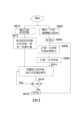
圖5係根據本發明一實施例,顯示一波束成形方法的流程圖。以下,根據圖1、2B-2D、3C及5,說明本發明波束成形方法,係適用於一電子裝置內的麥克風系統100。該電子裝置包含一可調機構(圖未示)。同時,假設以一訓練資料集、L個聲源(分為上述目標聲源集(T)及消除聲源集(C))、以及不同幾何形狀的麥克風陣列,來訓練上述已受訓的神經網路360T。其中,上述訓練資料集包含多個訓練樣本,而各訓練樣本包含配成對的訓練輸入資料以及訓練輸出資料(實際值)。FIG. 5 is a flow chart showing a beam forming method according to an embodiment of the present invention. Hereinafter, based on FIGS. 1, 2B-2D, 3C and 5, it will be described that the beamforming method of the present invention is applicable to the
步驟S502:於系統初始化後,由一感應器120輸出一目前感應輸出值Sr0。例如,圖3C的角度偵測單元380輸出一目前角度。Step S502: After the system is initialized, a
步驟S504:將參數值Sr設定等於Sr0。Step S504: Set the parameter value Sr equal to Sr0 .
步驟S506:由已受訓的神經網路360T,根據該目前感應輸出值Sr、該電子裝置中一參考點的位置以及Q個麥克風設在該電子裝置的位置,計算一目前麥克風座標集合M。圖2B的例子中,根據上述座標函數f(ED,)、原點Og(即位在筆記型電腦20之A/B面及C/D面的交叉點上的參考點)及輸入角度(即目前感應輸出值Sr),計算目前麥克風座標集合M。換言之,目前麥克風座標集合M的計算取決於感應器120的物理特性、參考點Og在該電子裝置的位置以及該Q個麥克風設在該電子裝置的位置。Step S506: The trained
步驟S508:由已受訓的神經網路360T,根據該目前麥克風座標集合M,決定該目標聲源集(T)及該消除聲源集(C)之間的一目前界線,亦即滿足””的要求。另一實施例中,由於多個麥克風座標集合M及多個感應輸出值Sr(例如多個角度)之間有一對一的對應性,因此無須計算目前麥克風座標集合M,依此,可捨去步驟S506,並修改步驟S508如下:由已受訓的神經網路360T,根據該參數值(即目前感應輸出值)Sr,決定該目標聲源集(T)及該消除聲源集(C)之間的一目前界線。由於步驟S506非必須,故在圖5以虛線矩形來表示。Step S508: The trained
步驟S510:由麥克風陣列110的Q個麥克風111-11Q,偵測聲音以輸出Q個音訊流b1[n]-bQ[n]。Step S510: The Q microphones 111-11Q of the
步驟S512:由特徵提取器330從Q個音訊流b1[n]-bQ[n]中提取出一特徵向量fv(i)。如圖3B的相關說明,特徵提取器330根據該Q個音訊流b1[n]-bQ[n]的目前音框i的音訊資料的Q個目前頻譜代表式F1(i)- FQ(i),提取出Q個量值頻譜mj(i)、Q個相位頻譜Pj(i)以及R個相位差頻譜pdl(i)),當作該Q個音訊流b1[n]-bQ[n]的目前音框i的一特徵向量fv(i)。Step S512: The
步驟S514:由已受訓神經網路360T根據上述目前界線,對上述特徵向量fv(i)進行空間濾波操作(包含或不包含去噪操作),以產生始於該目標聲源集(T)之波束成形輸出音訊流u[n]的音框i的音訊資料。舉例而言,若僅進行空間濾波操作,則波束成形輸出音訊流u[n]將會是始於該目標聲源集(T)之”有噪音”的音訊訊號。若進行空間濾波及去噪操作,則波束成形輸出音訊流u[n]將會是始於該目標聲源集(T)之無噪音(乾淨的)音訊訊號。Step S514: The trained
步驟S516:決定感應器120目前的感應輸出值Sr1是否等於先前感應輸出值Sr。若是,跳到步驟S514;否則,跳到步驟S518。Step S516: Determine whether the current sensing output value Sr1 of the
步驟S518:將參數值Sr設定等於Sr1。然後,跳到步驟S506。Step S518: Set the parameter value Sr equal to Sr1 . Then, jump to step S506.
雖然圖5中是以分離的步驟區塊來繪示,但根據期望的實施方式,步驟區塊(S502-S514)可以再進一步再分割、合併為較少的步驟區塊或刪除其中之一個或更多的步驟區塊。Although FIG. 5 is illustrated as separate step blocks, according to the desired implementation, the step blocks (S502-S514) may be further divided, merged into fewer step blocks, or delete one of them or More step blocks.
麥克風陣列110的Q個麥克風111-11Q可以是,例如,全向性(omni-directional)麥克風、雙向性(bi-directional)麥克風、指向性(directional)麥克風、或其組合。麥克風陣列110的Q個麥克風111-11Q可以用數位或類比的微機電系統(MicroElectrical-Mechanical System)麥克風來實施。請注意,當麥克風陣列110包含有指向性或雙向性麥克風時,電路設計者必須確認:無論麥克風陣列110的幾何形狀如何調整,該指向性或雙向性麥克風都必須能接收到始於該目標聲源集(T)之音訊訊號。對於耳機麥克風,麥克風陣列110的Q個麥克風111-11Q分別設在二個耳罩的周遭,例如二個耳罩上或被包覆在二個麥克風接臂(arm)(連接至上述二個耳罩)的二個前端;對於可穿戴式揚聲器或頸部揚聲器,麥克風陣列110的Q個麥克風111-11Q則分別嵌入二個前端。The Q microphones 111 - 11Q of the
以上提供多個實施例以說明本發明之原理及精神,然而,上述實施例可被適度調整,且本發明之原理亦適用於其他的電子裝置。舉例而言,耳機麥克風、或可穿戴式揚聲器、或頸部揚聲器,都能與一旋轉電位計(rotary potentiometer)(當作該感應器120)一起運作。由於旋轉電位計的結構及運作方式已為業界所熟知,在此不予贅述。一般而言,在耳機麥克風中,該旋轉電位計係設在該夾緊式頭帶的中間點(如:使用者的頭頂上),而在可穿戴式揚聲器(或頸部揚聲器)中,該旋轉電位計係設在該可調式或夾緊式頸帶的中間點(位在頸部後方)。須注意的是,本發明不受限於上述的電子裝置及感應器,而可適用於目前或將來發展之電子裝置及感應器,只要感應器能偵測到該電子裝置內的機構變化(相當於麥克風陣列110幾何形狀的改變)。此外,在未脫離本發明所揭示之精神下,上述實施例中的元件的排列或設置方式,可以不同於上述揭露內容或圖式來實施。Multiple embodiments are provided above to illustrate the principles and spirit of the present invention. However, the above-mentioned embodiments can be appropriately adjusted, and the principles of the present invention are also applicable to other electronic devices. For example, a headphone microphone, or a wearable speaker, or a neck speaker can operate with a rotary potentiometer (used as the sensor 120). Since the structure and operation of the rotary potentiometer are well known in the industry, they will not be described in detail here. Generally speaking, in headphone microphones, the rotary potentiometer is located at the midpoint of the clamp-on headband (e.g., on top of the user's head), while in wearable speakers (or neck speakers), the rotary potentiometer is The rotary potentiometer is located at the midpoint of the adjustable or clamping neck strap (located behind the neck). It should be noted that the present invention is not limited to the above-mentioned electronic devices and sensors, but can be applied to electronic devices and sensors currently or developed in the future, as long as the sensor can detect structural changes in the electronic device (equivalent to due to changes in the geometry of the microphone array 110). In addition, without departing from the spirit of the disclosure of the present invention, the arrangement or arrangement of the components in the above embodiments may be implemented differently from the above disclosure or drawings.
上述僅為本發明之較佳實施例而已,而並非用以限定本發明的申請專利範圍;凡其他未脫離本發明所揭示之精神下所完成的等效改變或修飾,均應包含在下述申請專利範圍內。The above are only preferred embodiments of the present invention, and are not used to limit the scope of the patent application of the present invention; all other equivalent changes or modifications completed without departing from the spirit disclosed by the present invention shall be included in the following applications within the scope of the patent.
20 筆記型電腦 30I、30T 神經網路模組 100 麥克風系統 110 麥克風陣列 111-11Q 麥克風 120 感應器 130、130T、130I 具幾何感知功能的波束成形器 201 A面(或背面) 202 B面(或正面) 203 C面(或頂面) 204 D面(或底面) 220、230 界線 250 陀螺儀 300I 於一推斷階段之麥克風系統 300T 於一訓練階段之麥克風系統 310、320 儲存裝置 311a 無噪音(或乾淨的)單麥克風時域原始音訊資料 311b 有噪音的單麥克風時域原始音訊資料 312 ”混合的”Q個麥克風時域擴增音訊資料 313 軟體程式 330 特徵提取器 350 處理器 360 神經網路 370 損失函數部 380 角度偵測單元 402 光學雷達感應器20
[圖1]係根據本發明,顯示麥克風系統之一方塊圖。 [圖2A]例示一筆記型電腦(laptop)的四個側面(A面(或背面)201、B面(或正面)202、C面(或頂面)203、D面(或底面)204)。 [圖2B]例示一筆記型電腦的螢幕210相對於水平線H,往上傾斜角。 [圖2C]例示電腦螢幕210從角往上傾斜至’角。 [圖2D]例示根據傾斜角’定義出新界線230。 [圖3A]係根據本發明一實施例,顯示於一訓練階段之麥克風系統之示意圖。 [圖3B]係根據本發明一實施例,顯示特徵提取器330的示意圖。 [圖3C]係根據本發明一實施例,顯示於一推斷(inference)階段之麥克風系統之示意圖。 [圖4A-4B]例示一光學雷達感應器(light detection and ranging (Lidar) sensor)用來偵測筆記型電腦螢幕是否往上或往下傾斜。 [圖5]係根據本發明一實施例,顯示一波束成形方法的流程圖。[Fig. 1] is a block diagram showing a microphone system according to the present invention. [Fig. 2A] Illustrating the four sides of a laptop (laptop) (side A (or back) 201, side B (or front) 202, side C (or top) 203, side D (or bottom) 204) . [FIG. 2B] An example of a
100 麥克風系統 110 麥克風陣列 111-11Q 麥克風 120 感應器 130 具幾何感知功能的波束成形器100
Claims (26)
Translated fromChineseApplications Claiming Priority (2)
| Application Number | Priority Date | Filing Date | Title |
|---|---|---|---|
| US202263313731P | 2022-02-25 | 2022-02-25 | |
| US63/313,731 | 2022-02-25 |
Publications (2)
| Publication Number | Publication Date |
|---|---|
| TW202335513A TW202335513A (en) | 2023-09-01 |
| TWI835246Btrue TWI835246B (en) | 2024-03-11 |
Family
ID=87761438
Family Applications (1)
| Application Number | Title | Priority Date | Filing Date |
|---|---|---|---|
| TW111130904ATWI835246B (en) | 2022-02-25 | 2022-08-17 | Microphone system and beamforming method |
Country Status (2)
| Country | Link |
|---|---|
| US (1) | US12231844B2 (en) |
| TW (1) | TWI835246B (en) |
Families Citing this family (1)
| Publication number | Priority date | Publication date | Assignee | Title |
|---|---|---|---|---|
| US20240249741A1 (en)* | 2023-01-25 | 2024-07-25 | Google Llc | Guided Speech Enhancement Network |
Citations (3)
| Publication number | Priority date | Publication date | Assignee | Title |
|---|---|---|---|---|
| CN111373769A (en)* | 2018-05-24 | 2020-07-03 | 索尼公司 | Information processing apparatus and information processing method |
| CN111512646A (en)* | 2017-09-12 | 2020-08-07 | 维思博Ai公司 | Low-delay audio enhancement |
| CN114026880A (en)* | 2019-08-28 | 2022-02-08 | 脸谱科技有限责任公司 | Inferring pinna information via beamforming to generate personalized spatial audio |
Family Cites Families (7)
| Publication number | Priority date | Publication date | Assignee | Title |
|---|---|---|---|---|
| US8150063B2 (en) | 2008-11-25 | 2012-04-03 | Apple Inc. | Stabilizing directional audio input from a moving microphone array |
| US8525868B2 (en) | 2011-01-13 | 2013-09-03 | Qualcomm Incorporated | Variable beamforming with a mobile platform |
| US9972339B1 (en)* | 2016-08-04 | 2018-05-15 | Amazon Technologies, Inc. | Neural network based beam selection |
| CN206711603U (en)* | 2017-04-06 | 2017-12-05 | 北京地平线信息技术有限公司 | Electronic equipment |
| US10477298B2 (en)* | 2017-09-08 | 2019-11-12 | Immersion Corporation | Rendering haptics on headphones with non-audio data |
| WO2020257491A1 (en)* | 2019-06-21 | 2020-12-24 | Ocelot Laboratories Llc | Self-calibrating microphone and loudspeaker arrays for wearable audio devices |
| US11353933B2 (en)* | 2020-05-27 | 2022-06-07 | Apple Inc. | Self-actuating hinge mechanism for electronic device |
- 2022
- 2022-08-17TWTW111130904Apatent/TWI835246B/enactive
- 2022-08-25USUS17/895,980patent/US12231844B2/enactiveActive
Patent Citations (3)
| Publication number | Priority date | Publication date | Assignee | Title |
|---|---|---|---|---|
| CN111512646A (en)* | 2017-09-12 | 2020-08-07 | 维思博Ai公司 | Low-delay audio enhancement |
| CN111373769A (en)* | 2018-05-24 | 2020-07-03 | 索尼公司 | Information processing apparatus and information processing method |
| CN114026880A (en)* | 2019-08-28 | 2022-02-08 | 脸谱科技有限责任公司 | Inferring pinna information via beamforming to generate personalized spatial audio |
Also Published As
| Publication number | Publication date |
|---|---|
| US12231844B2 (en) | 2025-02-18 |
| US20230276170A1 (en) | 2023-08-31 |
| TW202335513A (en) | 2023-09-01 |
Similar Documents
| Publication | Publication Date | Title |
|---|---|---|
| US12238497B2 (en) | Systems, methods, apparatus, and computer-readable media for gestural manipulation of a sound field | |
| US10909988B2 (en) | Systems and methods for displaying a user interface | |
| US8781142B2 (en) | Selective acoustic enhancement of ambient sound | |
| KR102191736B1 (en) | Method and apparatus for speech enhancement with artificial neural network | |
| KR101456866B1 (en) | Method and apparatus for extracting a target sound source signal from a mixed sound | |
| US9031256B2 (en) | Systems, methods, apparatus, and computer-readable media for orientation-sensitive recording control | |
| CN101779476B (en) | Omnidirectional dual microphone array | |
| JP4873913B2 (en) | Sound source separation system, sound source separation method, and acoustic signal acquisition apparatus | |
| TW202044236A (en) | Auto focus, auto focus within regions, and auto placement of beamformed microphone lobes with inhibition functionality | |
| US20220246161A1 (en) | Sound modification based on frequency composition | |
| KR20170129697A (en) | Microphone array speech enhancement technique | |
| KR20090037845A (en) | Method and apparatus for extracting target sound source signal from mixed signal | |
| TWI835246B (en) | Microphone system and beamforming method | |
| CN114023307B (en) | Sound signal processing method, speech recognition method, electronic device and storage medium | |
| Branda et al. | Motion sensors in automatic steering of hearing aids | |
| US11632625B2 (en) | Sound modification based on direction of interest | |
| JP5190859B2 (en) | Sound source separation device, sound source separation method, sound source separation program, and recording medium | |
| WO2013091677A1 (en) | Speech recognition method and system | |
| TWI861569B (en) | Microphone system | |
| TWI831513B (en) | Beamforming method and microphone system in boomless headset | |
| US12219329B2 (en) | Beamforming method and microphone system in boomless headset | |
| JP2017034519A (en) | Audio processing apparatus, audio processing system, and audio processing method | |
| WO2019178802A1 (en) | Method and device for estimating direction of arrival and electronics apparatus | |
| WO2025160029A1 (en) | Enhancing audio signals |