TWI832407B - Plasma auxiliary annealing system and annealing method thereof - Google Patents
Plasma auxiliary annealing system and annealing method thereofDownload PDFInfo
- Publication number
- TWI832407B TWI832407BTW111133258ATW111133258ATWI832407BTW I832407 BTWI832407 BTW I832407BTW 111133258 ATW111133258 ATW 111133258ATW 111133258 ATW111133258 ATW 111133258ATW I832407 BTWI832407 BTW I832407B
- Authority
- TW
- Taiwan
- Prior art keywords
- gas
- working gas
- plasma
- chamber
- temperature furnace
- Prior art date
Links
- 238000000137annealingMethods0.000titleclaimsabstractdescription59
- 238000000034methodMethods0.000titleclaimsdescription22
- 238000010494dissociation reactionMethods0.000claimsabstractdescription49
- 230000005593dissociationsEffects0.000claimsabstractdescription49
- 238000000605extractionMethods0.000claimsdescription15
- 150000002736metal compoundsChemical class0.000claimsdescription10
- 230000032258transportEffects0.000claimsdescription4
- 239000000284extractSubstances0.000claimsdescription3
- 239000007789gasSubstances0.000description78
- 239000010408filmSubstances0.000description18
- 229910052751metalInorganic materials0.000description7
- 239000002184metalSubstances0.000description7
- 239000013078crystalSubstances0.000description6
- PMHQVHHXPFUNSP-UHFFFAOYSA-Mcopper(1+);methylsulfanylmethane;bromideChemical compoundBr[Cu].CSCPMHQVHHXPFUNSP-UHFFFAOYSA-M0.000description5
- IJGRMHOSHXDMSA-UHFFFAOYSA-NAtomic nitrogenChemical compoundN#NIJGRMHOSHXDMSA-UHFFFAOYSA-N0.000description4
- 238000010586diagramMethods0.000description3
- 238000010438heat treatmentMethods0.000description3
- QGZKDVFQNNGYKY-UHFFFAOYSA-NAmmoniaChemical compoundNQGZKDVFQNNGYKY-UHFFFAOYSA-N0.000description2
- 230000007547defectEffects0.000description2
- 150000004767nitridesChemical class0.000description2
- 229910052757nitrogenInorganic materials0.000description2
- 229910002704AlGaNInorganic materials0.000description1
- 229910021529ammoniaInorganic materials0.000description1
- 238000000231atomic layer depositionMethods0.000description1
- 238000002425crystallisationMethods0.000description1
- 230000008025crystallizationEffects0.000description1
- 238000012986modificationMethods0.000description1
- 230000004048modificationEffects0.000description1
- KSOCVFUBQIXVDC-FMQUCBEESA-Np-azophenyltrimethylammoniumChemical compoundC1=CC([N+](C)(C)C)=CC=C1\N=N\C1=CC=C([N+](C)(C)C)C=C1KSOCVFUBQIXVDC-FMQUCBEESA-N0.000description1
- 238000001953recrystallisationMethods0.000description1
- 239000004065semiconductorSubstances0.000description1
- 230000000087stabilizing effectEffects0.000description1
- 239000010409thin filmSubstances0.000description1
Images


Classifications
- H—ELECTRICITY
- H01—ELECTRIC ELEMENTS
- H01L—SEMICONDUCTOR DEVICES NOT COVERED BY CLASS H10
- H01L21/00—Processes or apparatus adapted for the manufacture or treatment of semiconductor or solid state devices or of parts thereof
- H01L21/02—Manufacture or treatment of semiconductor devices or of parts thereof
- H01L21/02104—Forming layers
- H01L21/02107—Forming insulating materials on a substrate
- H01L21/02296—Forming insulating materials on a substrate characterised by the treatment performed before or after the formation of the layer
- H01L21/02318—Forming insulating materials on a substrate characterised by the treatment performed before or after the formation of the layer post-treatment
- H01L21/02337—Forming insulating materials on a substrate characterised by the treatment performed before or after the formation of the layer post-treatment treatment by exposure to a gas or vapour
- H01L21/0234—Forming insulating materials on a substrate characterised by the treatment performed before or after the formation of the layer post-treatment treatment by exposure to a gas or vapour treatment by exposure to a plasma
- H—ELECTRICITY
- H01—ELECTRIC ELEMENTS
- H01J—ELECTRIC DISCHARGE TUBES OR DISCHARGE LAMPS
- H01J37/00—Discharge tubes with provision for introducing objects or material to be exposed to the discharge, e.g. for the purpose of examination or processing thereof
- H01J37/32—Gas-filled discharge tubes
- H01J37/32431—Constructional details of the reactor
- H01J37/32458—Vessel
- H01J37/32522—Temperature
- H—ELECTRICITY
- H01—ELECTRIC ELEMENTS
- H01J—ELECTRIC DISCHARGE TUBES OR DISCHARGE LAMPS
- H01J37/00—Discharge tubes with provision for introducing objects or material to be exposed to the discharge, e.g. for the purpose of examination or processing thereof
- H01J37/32—Gas-filled discharge tubes
- H01J37/32431—Constructional details of the reactor
- H01J37/3244—Gas supply means
- H01J37/32449—Gas control, e.g. control of the gas flow
- F—MECHANICAL ENGINEERING; LIGHTING; HEATING; WEAPONS; BLASTING
- F27—FURNACES; KILNS; OVENS; RETORTS
- F27B—FURNACES, KILNS, OVENS OR RETORTS IN GENERAL; OPEN SINTERING OR LIKE APPARATUS
- F27B17/00—Furnaces of a kind not covered by any of groups F27B1/00 - F27B15/00
- F—MECHANICAL ENGINEERING; LIGHTING; HEATING; WEAPONS; BLASTING
- F27—FURNACES; KILNS; OVENS; RETORTS
- F27D—DETAILS OR ACCESSORIES OF FURNACES, KILNS, OVENS OR RETORTS, IN SO FAR AS THEY ARE OF KINDS OCCURRING IN MORE THAN ONE KIND OF FURNACE
- F27D19/00—Arrangements of controlling devices
- H—ELECTRICITY
- H01—ELECTRIC ELEMENTS
- H01J—ELECTRIC DISCHARGE TUBES OR DISCHARGE LAMPS
- H01J37/00—Discharge tubes with provision for introducing objects or material to be exposed to the discharge, e.g. for the purpose of examination or processing thereof
- H01J37/32—Gas-filled discharge tubes
- H01J37/32431—Constructional details of the reactor
- H01J37/32715—Workpiece holder
- H01J37/32724—Temperature
- H—ELECTRICITY
- H01—ELECTRIC ELEMENTS
- H01J—ELECTRIC DISCHARGE TUBES OR DISCHARGE LAMPS
- H01J37/00—Discharge tubes with provision for introducing objects or material to be exposed to the discharge, e.g. for the purpose of examination or processing thereof
- H01J37/32—Gas-filled discharge tubes
- H01J37/32431—Constructional details of the reactor
- H01J37/32798—Further details of plasma apparatus not provided for in groups H01J37/3244 - H01J37/32788; special provisions for cleaning or maintenance of the apparatus
- H01J37/32816—Pressure
- H01J37/32834—Exhausting
- H—ELECTRICITY
- H01—ELECTRIC ELEMENTS
- H01L—SEMICONDUCTOR DEVICES NOT COVERED BY CLASS H10
- H01L21/00—Processes or apparatus adapted for the manufacture or treatment of semiconductor or solid state devices or of parts thereof
- H01L21/02—Manufacture or treatment of semiconductor devices or of parts thereof
- H01L21/02104—Forming layers
- H01L21/02107—Forming insulating materials on a substrate
- H01L21/02109—Forming insulating materials on a substrate characterised by the type of layer, e.g. type of material, porous/non-porous, pre-cursors, mixtures or laminates
- H01L21/02112—Forming insulating materials on a substrate characterised by the type of layer, e.g. type of material, porous/non-porous, pre-cursors, mixtures or laminates characterised by the material of the layer
- H01L21/02172—Forming insulating materials on a substrate characterised by the type of layer, e.g. type of material, porous/non-porous, pre-cursors, mixtures or laminates characterised by the material of the layer the material containing at least one metal element, e.g. metal oxides, metal nitrides, metal oxynitrides or metal carbides
- H01L21/02175—Forming insulating materials on a substrate characterised by the type of layer, e.g. type of material, porous/non-porous, pre-cursors, mixtures or laminates characterised by the material of the layer the material containing at least one metal element, e.g. metal oxides, metal nitrides, metal oxynitrides or metal carbides characterised by the metal
- H01L21/02178—Forming insulating materials on a substrate characterised by the type of layer, e.g. type of material, porous/non-porous, pre-cursors, mixtures or laminates characterised by the material of the layer the material containing at least one metal element, e.g. metal oxides, metal nitrides, metal oxynitrides or metal carbides characterised by the metal the material containing aluminium, e.g. Al2O3
- H—ELECTRICITY
- H01—ELECTRIC ELEMENTS
- H01L—SEMICONDUCTOR DEVICES NOT COVERED BY CLASS H10
- H01L21/00—Processes or apparatus adapted for the manufacture or treatment of semiconductor or solid state devices or of parts thereof
- H01L21/67—Apparatus specially adapted for handling semiconductor or electric solid state devices during manufacture or treatment thereof; Apparatus specially adapted for handling wafers during manufacture or treatment of semiconductor or electric solid state devices or components ; Apparatus not specifically provided for elsewhere
- H01L21/67005—Apparatus not specifically provided for elsewhere
- H01L21/67011—Apparatus for manufacture or treatment
- H01L21/67017—Apparatus for fluid treatment
- H—ELECTRICITY
- H01—ELECTRIC ELEMENTS
- H01L—SEMICONDUCTOR DEVICES NOT COVERED BY CLASS H10
- H01L21/00—Processes or apparatus adapted for the manufacture or treatment of semiconductor or solid state devices or of parts thereof
- H01L21/67—Apparatus specially adapted for handling semiconductor or electric solid state devices during manufacture or treatment thereof; Apparatus specially adapted for handling wafers during manufacture or treatment of semiconductor or electric solid state devices or components ; Apparatus not specifically provided for elsewhere
- H01L21/67005—Apparatus not specifically provided for elsewhere
- H01L21/67011—Apparatus for manufacture or treatment
- H01L21/67098—Apparatus for thermal treatment
- H01L21/67109—Apparatus for thermal treatment mainly by convection
Landscapes
- Engineering & Computer Science (AREA)
- Physics & Mathematics (AREA)
- Plasma & Fusion (AREA)
- Analytical Chemistry (AREA)
- Chemical & Material Sciences (AREA)
- Microelectronics & Electronic Packaging (AREA)
- Computer Hardware Design (AREA)
- Power Engineering (AREA)
- Manufacturing & Machinery (AREA)
- General Physics & Mathematics (AREA)
- Condensed Matter Physics & Semiconductors (AREA)
- Mechanical Engineering (AREA)
- General Engineering & Computer Science (AREA)
- Heat Treatment Of Strip Materials And Filament Materials (AREA)
Abstract
Description
Translated fromChinese本發明關於一種退火系統及其退火方法,特別是關於一種電漿輔助退火系統及其退火方法。The present invention relates to an annealing system and an annealing method thereof, in particular to a plasma-assisted annealing system and an annealing method thereof.
在半導體產業中,使用高溫退火技術提升金屬薄膜品質已行之有年,傳統退火處理是將金屬薄膜加溫到高於再結晶溫度後維持一段時間,再緩緩的降溫,可有效的提高金屬薄膜的結晶性,進而提高其電氣性能,但由於傳統退火技術需要將金屬薄膜加熱至高溫並維持較長的時間,在功率消耗上相當巨大外,金屬薄膜之結晶性的提升也相當有限。In the semiconductor industry, high-temperature annealing technology has been used to improve the quality of metal films for many years. Traditional annealing treatment is to heat the metal film above the recrystallization temperature, maintain it for a period of time, and then slowly cool it down, which can effectively improve the metal film quality. However, since traditional annealing technology requires heating the metal film to a high temperature and maintaining it for a long time, which consumes a huge amount of power, the improvement in the crystallinity of the metal film is also quite limited.
本發明的主要目的是藉由電漿解離裝置解離之工作氣體輔助退火處理,可再進一步地提高金屬化合物薄膜的結晶品質。The main purpose of the present invention is to further improve the crystallization quality of metal compound thin films through the auxiliary annealing process of the working gas dissociated by the plasma dissociation device.
本發明之一種電漿輔助退火系統包含一高溫爐、一電漿解離裝置及一連接件,該高溫爐具有一氣體入口,該電漿解離裝置具有一工作氣體出口,該電漿解離裝置用以解離一工作氣體,並由該工作氣體出口排出解離之該工作氣體,該連接件之兩端分別連接該電漿解離裝置之該工作氣體出口及該高溫爐之該氣體入口,其中該電漿解離裝置解離之該工作氣體經由該連接件傳送至該高溫爐。A plasma-assisted annealing system of the present invention includes a high-temperature furnace, a plasma dissociation device and a connector. The high-temperature furnace has a gas inlet, the plasma dissociation device has a working gas outlet, and the plasma dissociation device is used to Dissociate a working gas, and discharge the dissociated working gas from the working gas outlet. Both ends of the connector are respectively connected to the working gas outlet of the plasma dissociation device and the gas inlet of the high-temperature furnace, wherein the plasma dissociation The working gas dissociated by the device is transmitted to the high temperature furnace through the connecting piece.
本發明之一種電漿輔助退火系統之退火方法包含一電漿解離裝置經由一連接件輸送一工作氣體至一高溫爐,其中該連接件之兩端分別連接該電漿解離裝置之一工作氣體出口及該高溫爐之一氣體入口;該電漿解離裝置解離該工作氣體,並將解離之該工作氣體經由該連接件輸送至該高溫爐;以及提高該高溫爐的一溫度,而對設置於該高溫爐中的一待處理元件進行退火。An annealing method of a plasma-assisted annealing system of the present invention includes a plasma dissociation device transporting a working gas to a high-temperature furnace through a connector, wherein both ends of the connector are respectively connected to a working gas outlet of the plasma dissociation device. and a gas inlet of the high-temperature furnace; the plasma dissociation device dissociates the working gas, and transports the dissociated working gas to the high-temperature furnace through the connecting piece; and increases a temperature of the high-temperature furnace, and sets the An element to be processed is annealed in a high temperature furnace.
本發明藉由該連接件之兩端分別連接該電漿解離裝置及該高溫爐,可讓電漿解離及退火處理分開在兩個腔體進行,除了能以解離之該工作氣體輔助退火處理,還可避免電漿的高溫影響退火溫度。In the present invention, the plasma dissociation device and the high-temperature furnace are respectively connected at both ends of the connector, so that the plasma dissociation and annealing processes can be performed separately in the two chambers. In addition to being able to use the dissociated working gas to assist the annealing process, It can also avoid the high temperature of plasma from affecting the annealing temperature.
請參閱第1圖,為本發明之一實施例,一種電漿輔助退火系統100的示意圖,在本實施例中,該電漿輔助退火系統100包含一高溫爐110、一電漿解離裝置120、一連接件130、一氣體供應裝置140及一流量控制器150。Please refer to Figure 1, which is a schematic diagram of a plasma-assisted
該高溫爐110具有一氣體入口111、一氣體出口112及一腔室113,該氣體入口111及該氣體出口112連通該腔室113,該氣體入口111用以流入氣體,該氣體出口112用以排出氣體。該電漿解離裝置120具有一工作氣體入口121及一工作氣體出口122,該工作氣體入口121連接該流量控制器150之一端,該工作氣體出口122連接該連接件130之一端,該流量控制器150之另一端連接該氣體供應裝置140,該連接件130之另一端則連接該高溫爐110之該氣體入口111。The
透過上述元件間的連接關係,當該氣體供應裝置140及該流量控制器150開啟時,該氣體供應裝置140、該流量控制器150、該電漿解離裝置120、該連接件130及該高溫爐110之該腔室113會相互連通,使得該氣體供應裝置140提供之一工作氣體可經由該流量控制器150、該電漿解離裝置120及該連接件130流動至該高溫爐110之該腔室113中。其中,該氣體供應裝置140可為儲存有該工作氣體之高壓氣瓶,當高壓氣瓶之開關開啟後即可透過該流量控制器150控制該工作氣體流入該電漿解離裝置120的流量。Through the connection relationship between the above components, when the
較佳的,該高溫爐110具有一控壓閥114、一抽氣裝置115及一壓力表116,該控壓閥114之兩端連接該高溫爐110之該氣體出口112及該抽氣裝置115,使該抽氣裝置115可經由該控壓閥114將該腔室113內的氣體抽出,該控壓閥114則用以控制該抽氣裝置115抽氣之一流量,而在該氣體供應裝置140提供該工作氣體至該腔室113時維持該腔室113內的壓力,該壓力表116則用以即時監測該腔室133的壓力大小是否符合製程需求。Preferably, the
當該電漿解離裝置120啟動時產生電漿,產生之電漿會解離通過該電漿解離裝置120之該工作氣體,再加上該抽氣裝置115將該腔室113內的氣體抽出,因此,由該電漿解離裝置120解離之該工作氣體會由該工作氣體出口122排出並經由該連接件130及該氣體入口111流入該腔室113中,最後再由該抽氣裝置115抽出。When the
該高溫爐110用以進行加熱而提高該腔室113內的溫度,以對設置於該腔室113內之一待處理元件S進行退火,該高溫爐110是透過一加熱元件(圖未繪出),例如加熱棒對該腔室113進行加熱。在本實施例中,該待處理元件S為一金屬化合物薄膜,例如GaN、AlN及AlGaN…等,對金屬化合物薄膜進行退火處理可有效提高其晶體品質及電氣性能。本實施例之該高溫爐110在進行退火處理的同時,該電漿解離裝置120持續將解離之該工作氣體導入該高溫爐110中,使該待處理元件S能在充滿解離之該工作氣體的氣氛中進行退火,能夠進一步地降低金屬化合物薄膜的缺陷密度,並提高金屬化合物薄膜的結晶品質。其中該工作氣體的種類與金屬化合物相關,例如該待處理元件S為金屬氮化物薄膜時,該工作氣體為氮氣、TMA、氨氣或其組合,可促進晶體的鍵結而提高其結晶性,但該工作氣體及該待處理元件S的種類並非本案之所限。The high-
請參閱第1圖,本實施例藉由該連接件130之兩端分別連接該電漿解離裝置120及該高溫爐110,可讓電漿解離及退火處理分開在兩個腔體進行,除了能以解離之該工作氣體輔助退火處理,還可避免該電漿的高溫影響退火溫度,以穩定該待處理元件S的晶體品質。較佳的,該連接件130具有一長度L,該長度L介於5至50公分之間,而能在避免該電漿的高溫影響退火溫度的情況下確保解離之該工作氣體能夠穩定的輸送至該腔室113。Please refer to Figure 1. In this embodiment, the
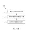
請參閱第2圖,其為該電漿輔助退火系統100之退火方法的流程圖,請搭配參閱第1圖,首先,於步驟11中開啟該氣體供應裝置140、該流量控制器150及該抽氣裝置115,以將儲存於該氣體供應裝置140內的該工作氣體經由該流量控制器150、該電漿解離裝置120輸送至該高溫爐110之該腔室113,並同時調整該流量控制器150及該控壓閥114,讓該腔室113之壓力維持於定壓。在本實施例中,該待處理元件S為一金屬氮化物薄膜,該工作氣體為氮氣,該流量控制器150控制該工作氣體流入該電漿解離裝置120的流量為1 L/min,經由該控壓閥114之控制所維持之該腔室113的壓力介於500 torr至0.1 torr之間。Please refer to Figure 2, which is a flow chart of the annealing method of the plasma-assisted
接著,於步驟12中開啟該電漿解離裝置120,使該電漿解離裝置120對通過之該工作氣體進行解離,解離之該工作氣體經由該連接件130輸送至該腔室113中。在本實施例中,該電漿解離裝置120的功率介於0.1 kW至5 kW之間、射頻頻率介於100 kHz至40 MHz之間。Next, in
最後,於步驟13中提高該高溫爐110的溫度並維持一段時間,以對該待處理元件S進行退火處理,在本實施例中,該高溫爐110的溫度為800度C,退火時間為1小時。Finally, in
請參閱第3圖,為一待處理元件分別以本實施例之電漿輔助退火方法進行退火、以傳統退火方法進行退火及未進行退火之CV特性曲線的比較圖,其中,該待處理元件為以電漿輔助式原子層沉積(Plasma-Enhanced Atomic Layer Deposition)而得之一氮化鋁薄膜。由CV特性曲線的比較圖可以看到以本實施例進行退火之氮化鋁薄膜於空乏區的斜率明顯較習知退火及未退火之氮化鋁薄膜大,空乏區的斜率較大可讓元件切換速度較快,證明以本實施例之電漿輔助退火方法進行退火之該氮化鋁薄膜的結晶品質有顯著提升。Please refer to Figure 3, which is a comparison chart of the CV characteristic curves of a device to be processed that is annealed by the plasma-assisted annealing method of this embodiment, annealed by the traditional annealing method, and not annealed. The device to be processed is An aluminum nitride film is obtained by Plasma-Enhanced Atomic Layer Deposition. From the comparison diagram of the CV characteristic curves, it can be seen that the slope of the depletion region of the aluminum nitride film annealed in this embodiment is obviously larger than that of the conventional annealed and unannealed aluminum nitride films. The larger slope of the depletion region allows the device to be The faster switching speed proves that the crystal quality of the aluminum nitride film annealed by the plasma-assisted annealing method of this embodiment has been significantly improved.
本實施例藉由該連接件130讓電漿解離及退火處理分開在兩個腔室進行,以避免該電漿解離裝置120產生之電漿溫度影響退火溫度而破壞該待處理元件S,此外,藉由解離之該工作氣體的輔助之退火處理,能夠降低金屬化合物薄膜的缺陷密度,並提高金屬化合物薄膜的結晶品質。This embodiment uses the
本發明之保護範圍當視後附之申請專利範圍所界定者為準,任何熟知此項技藝者,在不脫離本發明之精神和範圍內所作之任何變化與修改,均屬於本發明之保護範圍。The protection scope of the present invention shall be determined by the appended patent application scope. Any changes and modifications made by anyone familiar with this art without departing from the spirit and scope of the present invention shall fall within the protection scope of the present invention. .
100:電漿輔助退火系統110:高溫爐111:氣體入口112:氣體出口113:腔室114:控壓閥115:抽氣裝置116:壓力表120:電漿解離裝置121:工作氣體入口122:工作氣體出口130:連接件140:氣體供應裝置150:流量控制器S:待處理元件L:長度10:電漿輔助退火系統之退火方法11:輸送工作氣體至高溫爐12:電漿解離系統解離工作氣體13:提高高溫爐溫度進行退火100: Plasma assisted annealing system110:High temperature furnace111:Gas inlet112:Gas outlet113: Chamber114:Pressure control valve115: Air extraction device116: Pressure gauge120: Plasma dissociation device121: Working gas inlet122: Working gas outlet130: Connector140:Gas supply device150:Flow controllerS: component to be processedL: length10: Annealing method of plasma-assisted annealing system11: Transport working gas to high temperature furnace12: Plasma dissociation system dissociates working gas13: Increase the temperature of the high temperature furnace for annealing
第1圖:依據本發明之一實施例,一電漿輔助退火系統的示意圖。 第2圖:依據本發明之一實施例,一電漿輔助退火系統之退火方法的流程圖。 第3圖:分別以電漿輔助退火、傳統退火及未退火進行處理之氮化鋁薄膜的CV特性曲線比較圖。Figure 1: A schematic diagram of a plasma-assisted annealing system according to an embodiment of the present invention. Figure 2: A flow chart of an annealing method of a plasma-assisted annealing system according to an embodiment of the present invention. Figure 3: Comparison of CV characteristic curves of aluminum nitride films treated with plasma-assisted annealing, traditional annealing and no annealing.
100:電漿退火輔助系統100: Plasma annealing assist system
110:高溫爐110:High temperature furnace
111:氣體入口111:Gas inlet
112:氣體出口112:Gas outlet
113:腔室113: Chamber
114:控壓閥114:Pressure control valve
115:抽氣裝置115: Air extraction device
116:壓力表116: Pressure gauge
120:電漿解離裝置120: Plasma dissociation device
121:工作氣體入口121: Working gas inlet
122:工作氣體出口122: Working gas outlet
130:連接件130: Connector
140:氣體供應裝置140:Gas supply device
150:流量控制器150:Flow controller
L:長度L: length
S:待處理元件S: component to be processed
Claims (8)
Translated fromChinesePriority Applications (3)
| Application Number | Priority Date | Filing Date | Title |
|---|---|---|---|
| TW111133258ATWI832407B (en) | 2022-09-01 | 2022-09-01 | Plasma auxiliary annealing system and annealing method thereof |
| CN202211557386.7ACN117637422A (en) | 2022-09-01 | 2022-12-06 | Plasma-assisted annealing system and annealing method thereof |
| US18/079,069US20240079230A1 (en) | 2022-09-01 | 2022-12-12 | Plasma-assisted annealing system and method |
Applications Claiming Priority (1)
| Application Number | Priority Date | Filing Date | Title |
|---|---|---|---|
| TW111133258ATWI832407B (en) | 2022-09-01 | 2022-09-01 | Plasma auxiliary annealing system and annealing method thereof |
Publications (2)
| Publication Number | Publication Date |
|---|---|
| TWI832407Btrue TWI832407B (en) | 2024-02-11 |
| TW202412050A TW202412050A (en) | 2024-03-16 |
Family
ID=90022291
Family Applications (1)
| Application Number | Title | Priority Date | Filing Date |
|---|---|---|---|
| TW111133258ATWI832407B (en) | 2022-09-01 | 2022-09-01 | Plasma auxiliary annealing system and annealing method thereof |
Country Status (3)
| Country | Link |
|---|---|
| US (1) | US20240079230A1 (en) |
| CN (1) | CN117637422A (en) |
| TW (1) | TWI832407B (en) |
Citations (6)
| Publication number | Priority date | Publication date | Assignee | Title |
|---|---|---|---|---|
| US20030173072A1 (en)* | 2001-10-24 | 2003-09-18 | Vinegar Harold J. | Forming openings in a hydrocarbon containing formation using magnetic tracking |
| US20060030165A1 (en)* | 2004-08-04 | 2006-02-09 | Applied Materials, Inc. A Delaware Corporation | Multi-step anneal of thin films for film densification and improved gap-fill |
| TW200903718A (en)* | 2007-04-09 | 2009-01-16 | Harvard College | Cobalt nitride layers for copper interconnects and methods for forming them |
| TW201250791A (en)* | 2010-11-23 | 2012-12-16 | Soitec Silicon On Insulator | Methods of forming bulk III-nitride materials on metal-nitride growth template layers, and structures formed by such methods |
| CN104521046A (en)* | 2012-05-21 | 2015-04-15 | 布莱克光电有限公司 | Ciht power system |
| TWM636106U (en)* | 2022-09-01 | 2023-01-01 | 財團法人金屬工業研究發展中心 | Plasma-assisted annealing system |
- 2022
- 2022-09-01TWTW111133258Apatent/TWI832407B/enactive
- 2022-12-06CNCN202211557386.7Apatent/CN117637422A/enactivePending
- 2022-12-12USUS18/079,069patent/US20240079230A1/enactivePending
Patent Citations (6)
| Publication number | Priority date | Publication date | Assignee | Title |
|---|---|---|---|---|
| US20030173072A1 (en)* | 2001-10-24 | 2003-09-18 | Vinegar Harold J. | Forming openings in a hydrocarbon containing formation using magnetic tracking |
| US20060030165A1 (en)* | 2004-08-04 | 2006-02-09 | Applied Materials, Inc. A Delaware Corporation | Multi-step anneal of thin films for film densification and improved gap-fill |
| TW200903718A (en)* | 2007-04-09 | 2009-01-16 | Harvard College | Cobalt nitride layers for copper interconnects and methods for forming them |
| TW201250791A (en)* | 2010-11-23 | 2012-12-16 | Soitec Silicon On Insulator | Methods of forming bulk III-nitride materials on metal-nitride growth template layers, and structures formed by such methods |
| CN104521046A (en)* | 2012-05-21 | 2015-04-15 | 布莱克光电有限公司 | Ciht power system |
| TWM636106U (en)* | 2022-09-01 | 2023-01-01 | 財團法人金屬工業研究發展中心 | Plasma-assisted annealing system |
Also Published As
| Publication number | Publication date |
|---|---|
| TW202412050A (en) | 2024-03-16 |
| CN117637422A (en) | 2024-03-01 |
| US20240079230A1 (en) | 2024-03-07 |
Similar Documents
| Publication | Publication Date | Title |
|---|---|---|
| US7910497B2 (en) | Method of forming dielectric layers on a substrate and apparatus therefor | |
| TWI435376B (en) | Fluoride plasma treatment for high K gate stacks for defect passivation | |
| US20140034632A1 (en) | Apparatus and method for selective oxidation at lower temperature using remote plasma source | |
| US20090242511A1 (en) | Seasoning method for film-forming apparatus | |
| JP6413293B2 (en) | Film forming method and storage medium | |
| CN113862622A (en) | Preparation method of metal compound film | |
| US20180286691A1 (en) | Etching method and etching apparatus | |
| TWM636106U (en) | Plasma-assisted annealing system | |
| US20250285874A1 (en) | Surface treatment method, dry etching method, cleaning method, semiconductor device manufacturing method, and etching device | |
| TWI832407B (en) | Plasma auxiliary annealing system and annealing method thereof | |
| WO2007088692A1 (en) | Plasma etching method | |
| US9904299B2 (en) | Gas supply control method | |
| US9145605B2 (en) | Thin-film forming method and thin-film forming apparatus | |
| CN102420109A (en) | Method for improving capacitance uniformity of MIM device | |
| EP4047636A1 (en) | Dry etching method, method for producing semiconductor device, and etching device | |
| CN112736641A (en) | Passivation method of semiconductor device | |
| CN105304717A (en) | InN-based field effect transistor and manufacturing method thereof | |
| US20080254644A1 (en) | Method of Substrate Treatment, Computer-Readable Recording Medium, Substrate Treating Apparatus and Substrate Treating System | |
| JPH05326477A (en) | Method for removal of halogen from semiconductor substrate surface | |
| JP2022094914A (en) | Etching method and etching equipment | |
| JP5598407B2 (en) | Film forming apparatus and film forming method | |
| WO2022141354A1 (en) | Method for forming copper metal layer, and semiconductor structure | |
| TWI874798B (en) | Substrate processing method | |
| JP6165518B2 (en) | Plasma processing method and vacuum processing apparatus | |
| TW202020219A (en) | Chemical vapor deposition device, method for chemical vapor deposition device and non-transitory computer readable medium |