TWI829555B - Mouse structure - Google Patents
Mouse structureDownload PDFInfo
- Publication number
- TWI829555B TWI829555BTW112109639ATW112109639ATWI829555BTW I829555 BTWI829555 BTW I829555BTW 112109639 ATW112109639 ATW 112109639ATW 112109639 ATW112109639 ATW 112109639ATW I829555 BTWI829555 BTW I829555B
- Authority
- TW
- Taiwan
- Prior art keywords
- roller
- optical sensor
- housing
- rotating shaft
- surface features
- Prior art date
Links
Images


Classifications
- G—PHYSICS
- G06—COMPUTING OR CALCULATING; COUNTING
- G06F—ELECTRIC DIGITAL DATA PROCESSING
- G06F3/00—Input arrangements for transferring data to be processed into a form capable of being handled by the computer; Output arrangements for transferring data from processing unit to output unit, e.g. interface arrangements
- G06F3/01—Input arrangements or combined input and output arrangements for interaction between user and computer
- G06F3/03—Arrangements for converting the position or the displacement of a member into a coded form
- G06F3/033—Pointing devices displaced or positioned by the user, e.g. mice, trackballs, pens or joysticks; Accessories therefor
- G06F3/0362—Pointing devices displaced or positioned by the user, e.g. mice, trackballs, pens or joysticks; Accessories therefor with detection of 1D translations or rotations of an operating part of the device, e.g. scroll wheels, sliders, knobs, rollers or belts
- G—PHYSICS
- G06—COMPUTING OR CALCULATING; COUNTING
- G06F—ELECTRIC DIGITAL DATA PROCESSING
- G06F3/00—Input arrangements for transferring data to be processed into a form capable of being handled by the computer; Output arrangements for transferring data from processing unit to output unit, e.g. interface arrangements
- G06F3/01—Input arrangements or combined input and output arrangements for interaction between user and computer
- G06F3/03—Arrangements for converting the position or the displacement of a member into a coded form
- G06F3/0304—Detection arrangements using opto-electronic means
- G06F3/0312—Detection arrangements using opto-electronic means for tracking the rotation of a spherical or circular member, e.g. optical rotary encoders used in mice or trackballs using a tracking ball or in mouse scroll wheels
- G—PHYSICS
- G06—COMPUTING OR CALCULATING; COUNTING
- G06F—ELECTRIC DIGITAL DATA PROCESSING
- G06F3/00—Input arrangements for transferring data to be processed into a form capable of being handled by the computer; Output arrangements for transferring data from processing unit to output unit, e.g. interface arrangements
- G06F3/01—Input arrangements or combined input and output arrangements for interaction between user and computer
- G06F3/03—Arrangements for converting the position or the displacement of a member into a coded form
- G06F3/0304—Detection arrangements using opto-electronic means
- G06F3/0317—Detection arrangements using opto-electronic means in co-operation with a patterned surface, e.g. absolute position or relative movement detection for an optical mouse or pen positioned with respect to a coded surface
- G—PHYSICS
- G06—COMPUTING OR CALCULATING; COUNTING
- G06F—ELECTRIC DIGITAL DATA PROCESSING
- G06F3/00—Input arrangements for transferring data to be processed into a form capable of being handled by the computer; Output arrangements for transferring data from processing unit to output unit, e.g. interface arrangements
- G06F3/01—Input arrangements or combined input and output arrangements for interaction between user and computer
- G06F3/03—Arrangements for converting the position or the displacement of a member into a coded form
- G06F3/033—Pointing devices displaced or positioned by the user, e.g. mice, trackballs, pens or joysticks; Accessories therefor
- G06F3/0354—Pointing devices displaced or positioned by the user, e.g. mice, trackballs, pens or joysticks; Accessories therefor with detection of 2D relative movements between the device, or an operating part thereof, and a plane or surface, e.g. 2D mice, trackballs, pens or pucks
- G06F3/03543—Mice or pucks
Landscapes
- Engineering & Computer Science (AREA)
- General Engineering & Computer Science (AREA)
- Theoretical Computer Science (AREA)
- Human Computer Interaction (AREA)
- Physics & Mathematics (AREA)
- General Physics & Mathematics (AREA)
- Position Input By Displaying (AREA)
Abstract
Description
Translated fromChinese本發明是關於一種滑鼠結構。The present invention relates to a mouse structure.
隨著科技的日新月異,電腦的應用已成為生活中不可或缺的一部分。除了在一般的日常應用上,在商業上、在學業上、甚至在娛樂上,電腦的應用更是變得越來越多元化。With the rapid development of technology, computer applications have become an indispensable part of life. In addition to general daily applications, computer applications are becoming more and more diversified in business, academic and even entertainment.
眾所周知,滑鼠為電腦應用上一個常用的操作工具。目前業界的滑鼠,往往帶有五種基本功能,包括:有段落感的前滾、有段落感的後滾、下壓、左傾及右傾,而市場上的高階滑鼠,甚至可以切換飛梭模式,讓滑鼠的滾輪能快速且具精細度地轉動。As we all know, the mouse is a commonly used operating tool in computer applications. Currently, mice in the industry often have five basic functions, including: forward scrolling with a step-like feel, backward roll with a step-like feel, press down, left tilt, and right tilt. High-end mice on the market can even switch the shuttle. mode, allowing the mouse wheel to rotate quickly and with precision.
為了實現以上的功能,滑鼠一般需要配備多顆開關、編碼器以及複雜的電路連結等,這難免會造成製造成本增加及組裝過於複雜的問題。因此,業界一直致力於改善這個情況。In order to achieve the above functions, mice generally need to be equipped with multiple switches, encoders, and complex circuit connections, which will inevitably lead to increased manufacturing costs and overly complicated assembly. Therefore, the industry has been working hard to improve this situation.
本發明之目的之一在於提供一種滑鼠結構,其能有效簡化滑鼠結構的內部結構及相關的電路設計,也能有效節省製作用料及製作成本。One object of the present invention is to provide a mouse structure that can effectively simplify the internal structure and related circuit design of the mouse structure, and can also effectively save manufacturing materials and manufacturing costs.
根據本發明的一實施方式,一種滑鼠結構包含殼體、轉軸、支撐件、滾輪、光學感應器以及分析元件。支撐件連接於殼體與轉軸之間,並配置以支撐並容許轉軸相對殼體移動。轉軸穿越並連接滾輪,滾輪至少部分凸出於殼體外並具有複數個表面特徵。光學感應器設置於殼體並於滾輪定義受偵測範圍,表面特徵至少部分位於受偵測範圍,光學感應器配置以獲取受偵測範圍的複數個影像。分析元件訊號連接光學感應器,並根據影像判斷滾輪的移動模式。According to an embodiment of the present invention, a mouse structure includes a housing, a rotating shaft, a support, a roller, an optical sensor and an analysis element. The support member is connected between the housing and the rotating shaft, and is configured to support and allow the rotating shaft to move relative to the housing. The rotating shaft passes through and is connected to the roller, which at least partially protrudes outside the housing and has a plurality of surface features. The optical sensor is disposed on the housing and defines the detection range on the roller. The surface features are at least partially located in the detection range. The optical sensor is configured to acquire multiple images of the detection range. The analysis component signal is connected to the optical sensor and the movement pattern of the roller is determined based on the image.
在本發明一或多個實施方式中,上述之滾輪具有第一表面以及相對之兩第二表面,第一表面連接於第二表面之間,轉軸穿越第二表面,表面特徵位於第一表面,光學感應器垂直朝向第一表面。In one or more embodiments of the present invention, the above-mentioned roller has a first surface and two opposite second surfaces, the first surface is connected between the second surfaces, the rotating shaft passes through the second surface, and the surface features are located on the first surface. The optical sensor is vertically facing the first surface.
在本發明一或多個實施方式中,上述之光學感應器包含光源,光源配置以朝向受偵測範圍發出光線。In one or more embodiments of the present invention, the above-mentioned optical sensor includes a light source, and the light source is configured to emit light toward the detection range.
在本發明一或多個實施方式中,上述之滾輪具有第一表面以及相對之兩第二表面,第一表面連接於第二表面之間,轉軸穿越第二表面,表面特徵位於第二表面中之一者,光學感應器垂直朝向第二表面中設有表面特徵之一者。In one or more embodiments of the present invention, the above-mentioned roller has a first surface and two opposite second surfaces, the first surface is connected between the second surfaces, the rotating shaft passes through the second surface, and the surface features are located in the second surface. In one, the optical sensor is vertically oriented toward one of the surface features on the second surface.
在本發明一或多個實施方式中,上述之表面特徵中至少一者為標記。In one or more embodiments of the present invention, at least one of the above-mentioned surface features is a mark.
在本發明一或多個實施方式中,上述之表面特徵中至少一者為凹槽。In one or more embodiments of the present invention, at least one of the above-mentioned surface features is a groove.
在本發明一或多個實施方式中,上述之支撐件容許滾輪相對殼體彈性傾斜。In one or more embodiments of the present invention, the above-mentioned support member allows the roller to elastically tilt relative to the housing.
在本發明一或多個實施方式中,上述之支撐件容許滾輪朝向光學感應器彈性移動。In one or more embodiments of the present invention, the above-mentioned support member allows the roller to elastically move toward the optical sensor.
根據本發明的一實施方式,一種滑鼠結構包含殼體、轉軸、支撐件、第一滾輪、第二滾輪、光學感應器以及分析元件。支撐件連接於殼體與轉軸之間,並配置以支撐並容許轉軸相對殼體移動。轉軸穿越並連接第一滾輪,第一滾輪至少部分凸出於殼體外。轉軸穿越並連接第二滾輪,第二滾輪位於殼體內並與第一滾輪彼此分離,第二滾輪具有複數個表面特徵。光學感應器設置於殼體並於第二滾輪定義受偵測範圍,表面特徵至少部分位於受偵測範圍,光學感應器配置以獲取受偵測範圍的複數個影像。分析元件訊號連接光學感應器,並根據影像判斷第一滾輪的移動模式。According to an embodiment of the present invention, a mouse structure includes a housing, a rotating shaft, a support, a first roller, a second roller, an optical sensor and an analysis element. The support member is connected between the housing and the rotating shaft, and is configured to support and allow the rotating shaft to move relative to the housing. The rotating shaft passes through and is connected to the first roller, and the first roller at least partially protrudes outside the housing. The rotating shaft passes through and is connected to the second roller. The second roller is located in the housing and is separated from the first roller. The second roller has a plurality of surface features. The optical sensor is disposed on the housing and defines the detection range on the second roller. The surface features are at least partially located in the detection range. The optical sensor is configured to acquire a plurality of images of the detection range. The signal of the analyzing component is connected to the optical sensor, and the movement mode of the first roller is determined based on the image.
在本發明一或多個實施方式中,上述之第二滾輪具有第一表面以及相對之兩第二表面,第一表面連接於第二表面之間,轉軸穿越第二表面,表面特徵位於第一表面,光學感應器垂直朝向第一表面。In one or more embodiments of the present invention, the above-mentioned second roller has a first surface and two opposite second surfaces, the first surface is connected between the second surfaces, the rotating shaft passes through the second surface, and the surface features are located on the first surface. surface, the optical sensor is vertically oriented toward the first surface.
在本發明一或多個實施方式中,上述之光學感應器包含光源,光源配置以朝向受偵測範圍發出光線。In one or more embodiments of the present invention, the above-mentioned optical sensor includes a light source, and the light source is configured to emit light toward the detection range.
在本發明一或多個實施方式中,上述之第一滾輪具有第一表面以及相對之兩第二表面,第一表面連接於第二表面之間,轉軸穿越第二表面,表面特徵位於第二表面中之一者,光學感應器垂直朝向第二表面中設有表面特徵之一者。In one or more embodiments of the present invention, the above-mentioned first roller has a first surface and two opposite second surfaces, the first surface is connected between the second surfaces, the rotating shaft passes through the second surface, and the surface features are located on the second surface. On one of the surfaces, the optical sensor is vertically oriented toward one of the surface features on the second surface.
在本發明一或多個實施方式中,上述之表面特徵中至少一者為標記。In one or more embodiments of the present invention, at least one of the above-mentioned surface features is a mark.
在本發明一或多個實施方式中,上述之表面特徵中至少一者為凹槽。In one or more embodiments of the present invention, at least one of the above-mentioned surface features is a groove.
在本發明一或多個實施方式中,上述之支撐件容許第一滾輪相對殼體彈性傾斜。In one or more embodiments of the present invention, the above-mentioned support member allows the first roller to elastically tilt relative to the housing.
在本發明一或多個實施方式中,上述之支撐件容許第一滾輪朝向光學感應器彈性移動。In one or more embodiments of the present invention, the above-mentioned support member allows the first roller to elastically move toward the optical sensor.
本發明上述實施方式至少具有以下優點:The above-mentioned embodiments of the present invention have at least the following advantages:
(1)由於分析元件根據光學感應器於第一滾輪或第二滾輪上受偵測範圍所獲得的影像,便可透過演算法判斷第一滾輪是否轉動、左傾、右傾或下壓,且能判斷第一滾輪的轉動速度,因此能有效簡化滑鼠結構的內部結構,也能簡化涉及的電路設計。(1) Because the analysis element is based on the image obtained by the optical sensor in the detection range of the first roller or the second roller, it can determine whether the first roller is rotating, tilting left, tilting right, or pressing down through an algorithm, and can determine The rotation speed of the first roller can effectively simplify the internal structure of the mouse structure and also simplify the involved circuit design.
(2)由於滑鼠結構能省去傳統滑鼠中使用的開關及編碼器,故能進一步節省製作用料及製作成本。(2) Since the mouse structure can eliminate the switches and encoders used in traditional mice, it can further save production materials and production costs.
以下將以圖式揭露本發明之複數個實施方式,為明確說明起見,許多實務上的細節將在以下敘述中一併說明。然而,應瞭解到,這些實務上的細節不應用以限制本發明。也就是說,在本發明部分實施方式中,這些實務上的細節是非必要的。此外,為簡化圖式起見,一些習知慣用的結構與元件在圖式中將以簡單示意的方式繪示之,而在所有圖式中,相同的標號將用於表示相同或相似的元件。且若實施上為可能,不同實施例的特徵係可以交互應用。A plurality of embodiments of the present invention will be disclosed in the drawings below. For clarity of explanation, many practical details will be explained in the following description. However, it will be understood that these practical details should not limit the invention. That is to say, in some embodiments of the present invention, these practical details are not necessary. In addition, for the sake of simplifying the drawings, some commonly used structures and components are illustrated in the drawings in a simple schematic manner, and the same reference numerals are used to represent the same or similar components in all the drawings. . And if possible in implementation, features of different embodiments can be applied interchangeably.
除非另有定義,本文所使用的所有詞彙(包括技術和科學術語)具有其通常的意涵,其意涵係能夠被熟悉此領域者所理解。更進一步的說,上述之詞彙在普遍常用之字典中之定義,在本說明書的內容中應被解讀為與本發明相關領域一致的意涵。除非有特別明確定義,這些詞彙將不被解釋為理想化的或過於正式的意涵。Unless otherwise defined, all terms (including technical and scientific terms) used herein have their ordinary meanings that can be understood by one familiar with the art. Furthermore, the definitions of the above-mentioned words in commonly used dictionaries should be interpreted as meanings consistent with the relevant fields of the present invention in the content of this specification. Unless specifically defined, these terms will not be interpreted as having an idealized or overly formal meaning.
請參照第1~2圖。第1圖為繪示依照本發明一實施方式之滑鼠結構100的局部剖視圖。第2圖為繪示第1圖沿線段A-A的剖面圖。在本實施方式中,如第1~2圖所示,一種滑鼠結構100包含殼體110、轉軸120、支撐件130、第一滾輪140、光學感應器160以及分析元件170。支撐件130連接於殼體110與轉軸120之間,並配置以支撐並容許轉軸120相對殼體110移動。為簡化圖式,支撐件130僅以示意方式繪示。而且,應了解到,雖然支撐件130如第1圖所示係位於轉軸120的下方,然而,這並非用以限制本發明,本發明所屬技術領域中具有通常知識者,可視實際狀況,把支撐件130相對轉軸120設置於殼體110的適當位置上。轉軸120穿越並連接第一滾輪140,也就是說,支撐件130亦支撐並容許第一滾輪140相對殼體110移動,而第一滾輪140的移動模式包括相對殼體110轉動或左右傾側,也包括朝向殼體110作彈性移動並復位。再者,第一滾輪140至少部分凸出於殼體110外並具有複數個表面特徵141。具體而言,表面特徵141可為標記,而標記例如可為顏色不同的線條或刻度。光學感應器160設置於殼體110並於第一滾輪140定義受偵測範圍ZD(受偵測範圍ZD請見第2圖),表面特徵141至少部分位於受偵測範圍ZD,光學感應器160則配置以獲取受偵測範圍ZD的複數個影像。分析元件170訊號連接光學感應器160,並根據影像透過演算法判斷第一滾輪140的移動模式。具體而言,分析元件170可位於殼體110內,或位於殼體110外並設置於其他電子設備中,但本發明並不以此為限。Please refer to Figures 1 to 2. Figure 1 is a partial cross-sectional view of a
進一步而言,如第1~2圖所示,第一滾輪140具有第一表面142以及相對之兩第二表面143,第一表面142連接於第二表面143之間,轉軸120穿越第二表面143,而第一表面142係配置以供使用者以手指操控,以使第一滾輪140轉動、左傾、右傾或下壓。在本實施方式中,表面特徵141位於第一滾輪140的第一表面142,光學感應器160則垂直朝向第一表面142,並對齊表面特徵141。Furthermore, as shown in Figures 1 and 2, the
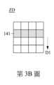
具體而言,當第一滾輪140轉動時,位於第一表面142的表面特徵141亦隨著轉動,而光學感應器160獲取受偵測範圍ZD的複數個影像,並根據影像中表面特徵141的位置變化而透過演算法判斷第一滾輪140轉動的方向及速度。請參照第3A~3D圖。第3A~3D圖為繪示第1圖的第一滾輪140上之受偵測範圍ZD的影像變化示意圖,其中表面特徵141朝第一方向D1移動。為簡化圖式,第3A~3D圖只繪示一個表面特徵141,且第3A~3D圖只繪示表面特徵141於受偵測範圍ZD內的影像變化。應理解到,若表面特徵141未進入或已離開受偵測範圍ZD,則受偵測範圍ZD內不具有表面特徵141。如第3A~3D圖所示,光學感應器160可對受偵測範圍ZD的影像以矩陣呈現。換句話說,光學感應器160更可配置以把於受偵測範圍ZD所獲取的影像轉為矩陣式的影像。當第一滾輪140朝第一方向D1轉動時,光學感應器160所獲取的影像順序記錄了表面特徵141於矩陣的位置變化,亦即表面特徵141朝第一方向D1的移動過程。藉此,分析元件170便能透過演算法判斷使用者使第一滾輪140朝第一方向D1轉動。進一步而言,藉由連續的影像中表面特徵141的移動距離,分析元件170便能判斷第一滾輪140的轉動速度。Specifically, when the
相似地,請參照第4A~4D圖。第4A~4D圖為繪示第1圖的第一滾輪140上之受偵測範圍ZD的影像變化示意圖,其中表面特徵141朝第二方向D2移動。如第4A~4D圖所示,當第一滾輪140朝相反於第一方向D1的第二方向D2轉動時,光學感應器160所獲取的影像順序記錄了表面特徵141於矩陣的位置變化,亦即表面特徵141朝第二方向D2的移動過程。藉此,分析元件170便能透過演算法判斷使用者使第一滾輪140朝第二方向D2轉動。Similarly, please refer to Figures 4A-4D. Figures 4A to 4D are schematic diagrams illustrating the image changes of the detected range ZD on the
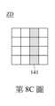
請參照第5圖及第6A~6D圖。第5圖為繪示第1圖之滑鼠結構100的局部剖視圖,其中第一滾輪140相對殼體110朝圖中右側傾斜。第6A~6D圖為繪示第5圖的第一滾輪140上之受偵測範圍ZD的影像變化示意圖,其中表面特徵141朝圖中左側移動。為使圖式更清楚易懂,第一滾輪140以較誇大的幅度的傾斜,而光學感應器160仍可對齊位於第一滾輪140上的表面特徵141。在本實施方式中,支撐件130支撐轉軸120並容許轉軸120及第一滾輪140相對殼體110彈性傾斜,而當使用者如第5圖所示使第一滾輪140相對殼體110朝圖中右側傾斜時,如第6A~6D圖所示,光學感應器160所獲取的影像順序記錄了表面特徵141於矩陣的位置變化,亦即表面特徵141朝圖中左側的移動過程。藉此,分析元件170便能透過演算法判斷使用者使第一滾輪140相對殼體110朝圖中右側彈性傾斜。Please refer to Figure 5 and Figures 6A to 6D. FIG. 5 is a partial cross-sectional view of the
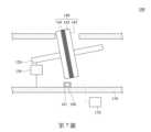
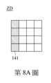
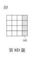
相似地,請參照第7圖及第8A~8D圖。第7圖為繪示第1圖之滑鼠結構100的局部剖視圖,其中第一滾輪140相對殼體110朝圖中左側傾斜。第8A~8D圖為繪示第7圖的第一滾輪140上之受偵測範圍ZD的影像變化示意圖,其中表面特徵141朝圖中右側移動。同樣,為使圖式更清楚易懂,第一滾輪140以較誇大的幅度的傾斜,而光學感應器160仍可對齊位於第一滾輪140上的表面特徵141。在本實施方式中,當使用者如第7圖所示使第一滾輪140相對殼體110朝圖中左側傾斜時,如第8A~8D圖所示,光學感應器160所獲取的影像順序記錄了表面特徵141於矩陣的位置變化,亦即表面特徵141朝圖中右側的移動過程。藉此,分析元件170便能透過演算法判斷使用者使第一滾輪140相對殼體110朝圖中左側彈性傾斜。Similarly, please refer to Figure 7 and Figures 8A-8D. FIG. 7 is a partial cross-sectional view of the
請回到第1圖。在本實施方式中,如第1圖所示,光學感應器160包含光源161,光源161配置以朝向受偵測範圍ZD發出光線。再者,在本實施方式中,支撐件130支撐轉軸120並容許轉軸120及第一滾輪140朝向光學感應器160彈性移動。當使用者壓向第一滾輪140時,第一滾輪140朝向光學感應器160移動,然後第一滾輪140彈性復位並遠離光學感應器160。在此過程中,由於第一滾輪140的第一表面142與光學感應器160之間的距離先縮減後回復,因此,受光源161的光線照射的受偵測範圍ZD之亮度也對應改變,光學感應器160因而獲取到亮度先提高後回復的連續影像。藉此,分析元件170便能透過演算法判斷使用者對第一滾輪140進行下壓。Please go back to picture 1. In this embodiment, as shown in FIG. 1 , the
簡單而言,由於分析元件170根據光學感應器160於第一滾輪140上受偵測範圍ZD所獲得的影像,便可透過演算法判斷第一滾輪140是否轉動、左傾、右傾或下壓,且能判斷第一滾輪140的轉動速度,因此能有效簡化滑鼠結構100的內部結構,也能簡化涉及的電路設計。To put it simply, because the
再者,由於滑鼠結構100能省去傳統滑鼠中使用的開關及編碼器,故能進一步節省製作用料及製作成本。Furthermore, since the
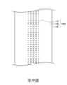
請參照第9圖。第9圖為繪示第1圖之第一滾輪140的局部放大示意圖,其中表面特徵141呈塊狀。在本實施方式中,表面特徵141可為呈塊狀的標記。如第9圖所示,表面特徵141為圓形塊狀。根據實際狀況,在其他實施方式中,表面特徵141可為三角形、矩形、多邊形或其他外形的塊狀。Please refer to Figure 9. Figure 9 is a partially enlarged schematic diagram of the
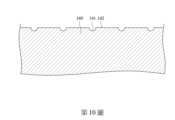
請參照第10圖。第10圖為繪示第1圖之第一滾輪140的局部放大剖面圖,其中表面特徵141為凹槽。在本實施方式中,如第10圖所示,表面特徵141為第一表面142上的凹槽,而凹槽的深度可根據實際狀況調整。Please refer to Figure 10. Figure 10 is a partial enlarged cross-sectional view of the
請參照第11~12圖。第11圖為繪示依照本發明另一實施方式之滑鼠結構100的局部剖視圖,其中光學感應器160垂直朝向第二表面143。第12圖為繪示第11圖沿線段B-B的正視圖。在本實施方式中,如第11~12圖所示,表面特徵141位於第一滾輪140的第二表面143中之一者,而光學感應器160垂直朝向第二表面143中設有表面特徵141之一者。Please refer to Figures 11 and 12. Figure 11 is a partial cross-sectional view of a
請參照第13A~13D圖。第13A~13D圖為繪示第12圖的第一滾輪140上之受偵測範圍ZD的影像變化示意圖,其中表面特徵141朝第一方向D1移動。如第13A~13D圖所示,當第一滾輪140朝第一方向D1轉動時,光學感應器160所獲取的影像順序記錄了表面特徵141朝第一方向D1的移動過程。藉此,分析元件170便能透過演算法判斷使用者使第一滾輪140朝第一方向D1轉動。進一步而言,藉由連續的影像中表面特徵141的移動距離,分析元件170便能判斷第一滾輪140的轉動速度。Please refer to Figures 13A to 13D. Figures 13A to 13D are schematic diagrams illustrating the image changes of the detected range ZD on the
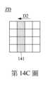
請參照第14A~14D圖。第14A~14D圖為繪示第12圖的第一滾輪140上之受偵測範圍ZD的影像變化示意圖,其中表面特徵141朝第二方向D2移動。如第14a~14d圖所示,當第一滾輪140朝相反於第一方向D1的第二方向D2轉動時,光學感應器160所獲取的影像順序記錄了表面特徵141朝第二方向D2的移動過程。藉此,分析元件170便能透過演算法判斷使用者使第一滾輪140朝第二方向D2轉動。Please refer to Figures 14A to 14D. Figures 14A to 14D are schematic diagrams illustrating the image changes of the detected range ZD on the
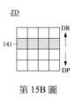
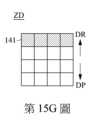
請參照第15A~15G圖。第15A~15G圖為繪示第12圖的第一滾輪140上之受偵測範圍ZD的影像變化示意圖,其中表面特徵141朝來回方向移動。具體而言,當使用者沿施壓方向DP壓向第一滾輪140時,第一滾輪140沿施壓方向DP移動,然後第一滾輪140彈性復位並沿相反於施壓方向DP的復位方向DR移動,因此,如第15A~15G圖所示,光學感應器160所獲取的影像順序記錄了表面特徵141朝下移動後再朝上移動的過程。藉此,分析元件170便能透過演算法判斷使用者對第一滾輪140進行下壓。Please refer to Figures 15A ~ 15G. Figures 15A to 15G are schematic diagrams illustrating the image changes of the detected range ZD on the
請參照第16~17圖。第16~17圖為繪示第11圖之滑鼠結構100的局部剖視圖,其中滾輪相對殼體110分別朝圖中右側及左側傾斜。在本實施方式中,光學感應器160包含光源161,而光源161配置以朝向受偵測範圍ZD(受偵測範圍ZD請見第12圖)發出光線。當使用者如第16~17圖所示使第一滾輪140相對殼體110朝圖中右側或左側傾斜時,第一滾輪140的第二表面143與光學感應器160之間的距離將會增加或縮減,因此,受光源161的光線照射的受偵測範圍ZD之亮度也對應改變,光學感應器160因而獲取到亮度漸弱或亮度漸強的連續影像。藉此,分析元件170便能透過演算法判斷使用者使第一滾輪140朝圖中右側及朝圖中左側傾斜。Please refer to Figures 16-17. Figures 16-17 are partial cross-sectional views of the
請參照第18~19圖。第18圖為繪示依照本發明再一實施方式之滑鼠結構100的局部剖視圖,其中光學感應器160垂直朝向第二滾輪150的第一表面152。第19圖為繪示第18圖沿線段C-C的正視圖。在本實施方式中,如第18~19圖所示,滑鼠結構100更包含第二滾輪150。轉軸120穿越並連接第二滾輪150,第二滾輪150位於殼體110內並與第一滾輪140彼此分離,第二滾輪150具有複數個表面特徵151。光學感應器160設置於殼體110並於第二滾輪150定義受偵測範圍ZD(受偵測範圍ZD請見第19圖),表面特徵151至少部分位於受偵測範圍ZD。光學感應器160配置以獲取受偵測範圍ZD的複數個影像。分析元件170訊號連接光學感應器160,並根據影像透過演算法判斷第一滾輪140的移動模式。在本實施方式中,第一滾輪140並不具有上述的表面特徵141。Please refer to Figures 18-19. FIG. 18 is a partial cross-sectional view of a
進一步而言,如第18~19圖所示,第二滾輪150具有第一表面152以及相對之兩第二表面153,第一表面152連接於第二表面153之間,轉軸120穿越第二表面153。在本實施方式中,表面特徵151位於第二滾輪150的第一表面152,光學感應器160則垂直朝向第二滾輪150的第一表面152,並對齊表面特徵151。在本實施方式中,光學感應器160於受偵測範圍ZD獲取影像,以及分析元件170透過演算法判斷第二滾輪150的移動模式的具體作業過程,相同於上述表面特徵141位於第一滾輪140的第一表面142的實施方式,在此不再贅述。再者,由於轉軸120穿越並連接第一滾輪140及第二滾輪150,且第二滾輪150與第一滾輪140彼此分離,因此,分析元件170可藉由第二滾輪150的移動模式而判斷第一滾輪140的移動模式。Furthermore, as shown in Figures 18 and 19, the
請參照第20~21圖。第20圖為繪示依照本發明再一實施方式之滑鼠結構100的局部剖視圖,其中光學感應器160垂直朝向第二滾輪150的第二表面153。第21圖為繪示第20圖沿線段D-D的正視圖。在本實施方式中,如第20~21圖所示,表面特徵151(請見第21圖)位於第二滾輪150的第二表面153中之一者,而光學感應器160垂直朝向第二表面153中設有表面特徵151之一者。在本實施方式中,光學感應器160於受偵測範圍ZD獲取影像,以及分析元件170透過演算法判斷第二滾輪150的移動模式的具體作業過程,相同於上述表面特徵141位於第一滾輪140的第二表面143的實施方式,在此不再贅述。由於轉軸120穿越並連接第一滾輪140及第二滾輪150,且第二滾輪150與第一滾輪140彼此分離,因此,分析元件170可藉由第二滾輪150的移動模式而判斷第一滾輪140的移動模式。在本實施方式中,第一滾輪140並不具有上述的表面特徵141。Please refer to Figures 20-21. FIG. 20 is a partial cross-sectional view of a
綜上所述,本發明上述實施方式所揭露的技術方案至少具有以下優點:To sum up, the technical solutions disclosed in the above embodiments of the present invention have at least the following advantages:
(1)由於分析元件根據光學感應器於第一滾輪或第二滾輪上受偵測範圍所獲得的影像,便可透過演算法判斷第一滾輪是否轉動、左傾、右傾或下壓,且能判斷第一滾輪的轉動速度,因此能有效簡化滑鼠結構的內部結構,也能簡化涉及的電路設計。(1) Because the analysis element is based on the image obtained by the optical sensor in the detection range of the first roller or the second roller, it can determine whether the first roller is rotating, tilting left, tilting right, or pressing down through an algorithm, and can determine The rotation speed of the first roller can effectively simplify the internal structure of the mouse structure and also simplify the involved circuit design.
(2)由於滑鼠結構能省去傳統滑鼠中使用的開關及編碼器,故能進一步節省製作用料及製作成本。(2) Since the mouse structure can eliminate the switches and encoders used in traditional mice, it can further save production materials and production costs.
雖然本發明已以實施方式揭露如上,然其並非用以限定本發明,任何熟習此技藝者,在不脫離本發明之精神和範圍內,當可作各種之更動與潤飾,因此本發明之保護範圍當視後附之申請專利範圍所界定者為準。Although the present invention has been disclosed in the above embodiments, it is not intended to limit the present invention. Anyone skilled in the art can make various modifications and modifications without departing from the spirit and scope of the present invention. Therefore, the protection of the present invention is The scope shall be determined by the appended patent application scope.
100:滑鼠結構 110:殼體 120:轉軸 130:支撐件 140:第一滾輪 141:表面特徵 142:第一表面 143:第二表面 150:第二滾輪 151:表面特徵 152:第一表面 153:第二表面 160:光學感應器 161:光源 170:分析元件 A-A,B-B,C-C,D-D:線段 D1:第一方向 D2:第二方向 DP:施壓方向 DR:復位方向 ZD:受偵測範圍100: Mouse structure 110: Shell 120:Rotating axis 130:Support 140:First roller 141:Surface features 142: First surface 143: Second surface 150:Second roller 151:Surface features 152: First surface 153: Second surface 160: Optical sensor 161:Light source 170:Analysis component A-A,B-B,C-C,D-D: line segments D1: first direction D2: second direction DP: direction of pressure DR: reset direction ZD: Detected range
第1圖為繪示依照本發明一實施方式之滑鼠結構的局部剖視圖。 第2圖為繪示第1圖沿線段A-A的正視圖。 第3A~3D圖為繪示第1圖的第一滾輪上之受偵測範圍的影像變化示意圖,其中表面特徵朝第一方向移動。 第4A~4D圖為繪示第1圖的第一滾輪上之受偵測範圍的影像變化示意圖,其中表面特徵朝第二方向移動。 第5圖為繪示第1圖之滑鼠結構的局部剖視圖,其中第一滾輪相對殼體朝圖中右側傾斜。 第6A~6D圖為繪示第5圖的第一滾輪上之受偵測範圍的影像變化示意圖,其中表面特徵朝圖中左側移動。 第7圖為繪示第1圖之滑鼠結構的局部剖視圖,其中第一滾輪相對殼體朝圖中左側傾斜。 第8A~8D圖為繪示第7圖的第一滾輪上之受偵測範圍的影像變化示意圖,其中表面特徵朝圖中右側移動。 第9圖為繪示第1圖之第一滾輪的局部放大示意圖,其中表面特徵呈塊狀。 第10圖為繪示第1圖之第一滾輪的局部放大剖面圖,其中表面特徵為凹槽。 第11圖為繪示依照本發明另一實施方式之滑鼠結構的局部剖視圖,其中光學感應器垂直朝向第二表面。 第12圖為繪示第11圖沿線段B-B的正視圖。 第13A~13D圖為繪示第12圖的第一滾輪上之受偵測範圍的影像變化示意圖,其中表面特徵朝第一方向移動。 第14A~14D圖為繪示第12圖的第一滾輪上之受偵測範圍的影像變化示意圖,其中表面特徵朝第二方向移動。 第15A~15G圖為繪示第12圖的第一滾輪上之受偵測範圍的影像變化示意圖,其中表面特徵朝來回方向移動。 第16圖為繪示第11圖之滑鼠結構的局部剖視圖,其中滾輪相對殼體朝圖中右側傾斜。 第17圖為繪示第11圖之滑鼠結構的局部剖視圖,其中滾輪相對殼體朝圖中左側傾斜。 第18圖為繪示依照本發明再一實施方式之滑鼠結構的局部剖視圖,其中光學感應器垂直朝向第二滾輪的第一表面。 第19圖為繪示第18圖沿線段C-C的正視圖。 第20圖為繪示依照本發明再一實施方式之滑鼠結構的局部剖視圖,其中光學感應器垂直朝向第二滾輪的第二表面。 第21圖為繪示第20圖沿線段D-D的正視圖。Figure 1 is a partial cross-sectional view illustrating the structure of a mouse according to an embodiment of the present invention. Figure 2 is a front view along line segment A-A in Figure 1 . Figures 3A to 3D are schematic diagrams illustrating the image changes of the detected range on the first roller in Figure 1, in which the surface features move toward the first direction. Figures 4A to 4D are schematic diagrams illustrating the image changes of the detected range on the first roller in Figure 1, in which the surface features move toward the second direction. Figure 5 is a partial cross-sectional view of the mouse structure of Figure 1, in which the first roller is tilted toward the right side of the figure relative to the housing. Figures 6A to 6D are schematic diagrams illustrating the image changes of the detected range on the first roller in Figure 5, in which the surface features move toward the left side of the figure. Figure 7 is a partial cross-sectional view of the mouse structure of Figure 1, in which the first roller is tilted toward the left side of the figure relative to the housing. Figures 8A to 8D are schematic diagrams illustrating the image changes of the detected range on the first roller in Figure 7, in which the surface features move toward the right side of the figure. Figure 9 is a partially enlarged schematic diagram of the first roller in Figure 1, in which the surface features are block-shaped. Figure 10 is a partial enlarged cross-sectional view of the first roller of Figure 1, in which the surface features are grooves. Figure 11 is a partial cross-sectional view of a mouse structure according to another embodiment of the present invention, in which the optical sensor is vertically facing the second surface. Figure 12 is a front view along line segment B-B in Figure 11 . Figures 13A to 13D are schematic diagrams illustrating the image changes of the detected range on the first roller in Figure 12, in which the surface features move toward the first direction. Figures 14A to 14D are schematic diagrams illustrating the image changes of the detected range on the first roller in Figure 12, in which the surface features move toward the second direction. Figures 15A to 15G are schematic diagrams illustrating the image changes of the detected range on the first roller in Figure 12, in which the surface features move in the back and forth direction. Figure 16 is a partial cross-sectional view of the mouse structure of Figure 11, in which the scroll wheel is tilted toward the right side of the figure relative to the housing. Figure 17 is a partial cross-sectional view of the mouse structure of Figure 11, in which the scroll wheel is tilted toward the left side of the figure relative to the housing. Figure 18 is a partial cross-sectional view of a mouse structure according to yet another embodiment of the present invention, in which the optical sensor is vertically facing the first surface of the second roller. Figure 19 is a front view along line segment C-C in Figure 18. Figure 20 is a partial cross-sectional view of a mouse structure according to yet another embodiment of the present invention, in which the optical sensor is vertically facing the second surface of the second roller. Figure 21 is a front view along line D-D in Figure 20.
國內寄存資訊(請依寄存機構、日期、號碼順序註記) 無 國外寄存資訊(請依寄存國家、機構、日期、號碼順序註記) 無Domestic storage information (please note in order of storage institution, date and number) without Overseas storage information (please note in order of storage country, institution, date, and number) without
100:滑鼠結構100: Mouse structure
110:殼體110: Shell
120:轉軸120:Rotating axis
130:支撐件130:Support
140:第一滾輪140:First roller
141:表面特徵141:Surface features
142:第一表面142: First surface
143:第二表面143: Second surface
160:光學感應器160: Optical sensor
161:光源161:Light source
170:分析元件170:Analysis component
A-A:線段A-A: line segment
Claims (10)
Translated fromChinesePriority Applications (2)
| Application Number | Priority Date | Filing Date | Title |
|---|---|---|---|
| TW112109639ATWI829555B (en) | 2023-03-15 | 2023-03-15 | Mouse structure |
| US18/447,286US20240310935A1 (en) | 2023-03-15 | 2023-08-09 | Mouse structure |
Applications Claiming Priority (1)
| Application Number | Priority Date | Filing Date | Title |
|---|---|---|---|
| TW112109639ATWI829555B (en) | 2023-03-15 | 2023-03-15 | Mouse structure |
Publications (2)
| Publication Number | Publication Date |
|---|---|
| TWI829555Btrue TWI829555B (en) | 2024-01-11 |
| TW202439094A TW202439094A (en) | 2024-10-01 |
Family
ID=90459054
Family Applications (1)
| Application Number | Title | Priority Date | Filing Date |
|---|---|---|---|
| TW112109639ATWI829555B (en) | 2023-03-15 | 2023-03-15 | Mouse structure |
Country Status (2)
| Country | Link |
|---|---|
| US (1) | US20240310935A1 (en) |
| TW (1) | TWI829555B (en) |
Citations (6)
| Publication number | Priority date | Publication date | Assignee | Title |
|---|---|---|---|---|
| US20040174336A1 (en)* | 2003-03-07 | 2004-09-09 | Microsoft Corporation | Scroll wheel assembly for scrolling an image in multiple directions |
| TW200841221A (en)* | 2007-04-14 | 2008-10-16 | Darfon Electronics Corp | Input device |
| TWM365506U (en)* | 2009-04-20 | 2009-09-21 | Pixart Imaging Inc | Mouse wheel assembly |
| CN108205379A (en)* | 2016-12-16 | 2018-06-26 | 微软技术许可有限责任公司 | Roll wheel assembly and mouse |
| CN110647247A (en)* | 2018-06-27 | 2020-01-03 | 罗技欧洲公司 | Multimodal scroll wheel for input devices |
| US20210018993A1 (en)* | 2016-06-23 | 2021-01-21 | Swiftpoint Limited | Computer mouse |
Family Cites Families (2)
| Publication number | Priority date | Publication date | Assignee | Title |
|---|---|---|---|---|
| US10704931B2 (en)* | 2016-08-22 | 2020-07-07 | Pixart Imaging Inc. | Optical detecting device capable of determining shift of a multi-axis instruction outputting mechanism |
| EP4311513A1 (en)* | 2022-07-25 | 2024-01-31 | Stryker European Operations Limited | Surgical input device, system and method |
- 2023
- 2023-03-15TWTW112109639Apatent/TWI829555B/enactive
- 2023-08-09USUS18/447,286patent/US20240310935A1/ennot_activeAbandoned
Patent Citations (6)
| Publication number | Priority date | Publication date | Assignee | Title |
|---|---|---|---|---|
| US20040174336A1 (en)* | 2003-03-07 | 2004-09-09 | Microsoft Corporation | Scroll wheel assembly for scrolling an image in multiple directions |
| TW200841221A (en)* | 2007-04-14 | 2008-10-16 | Darfon Electronics Corp | Input device |
| TWM365506U (en)* | 2009-04-20 | 2009-09-21 | Pixart Imaging Inc | Mouse wheel assembly |
| US20210018993A1 (en)* | 2016-06-23 | 2021-01-21 | Swiftpoint Limited | Computer mouse |
| CN108205379A (en)* | 2016-12-16 | 2018-06-26 | 微软技术许可有限责任公司 | Roll wheel assembly and mouse |
| CN110647247A (en)* | 2018-06-27 | 2020-01-03 | 罗技欧洲公司 | Multimodal scroll wheel for input devices |
Also Published As
| Publication number | Publication date |
|---|---|
| TW202439094A (en) | 2024-10-01 |
| US20240310935A1 (en) | 2024-09-19 |
Similar Documents
| Publication | Publication Date | Title |
|---|---|---|
| KR101044102B1 (en) | How to move an image with respect to an input device and a display screen intended to be moved relative to the support surface | |
| US11442559B2 (en) | Dual-mode optical input device | |
| US8711093B2 (en) | Input device with photodetector pairs | |
| JP5225338B2 (en) | Movable touchpad with added features | |
| JP4785983B2 (en) | Solid state object position detector | |
| US7081883B2 (en) | Low-profile multi-channel input device | |
| JPH08504047A (en) | Compact mouse structure | |
| TWI396123B (en) | Optical touch system and operating method thereof | |
| US20050146500A1 (en) | Pointing Device For Multiple-Dimensional Scrolling Control | |
| US11625108B2 (en) | Working range and lift detection in an input device | |
| US20120268375A1 (en) | Mouse wheel assembly | |
| TWI829555B (en) | Mouse structure | |
| TWI598779B (en) | mouse | |
| CN101882029B (en) | Optical touch system and operating method thereof | |
| CN118708073A (en) | Mouse structure | |
| TW202242616A (en) | Input device | |
| TWI603231B (en) | Cursor control device and method | |
| CN100390719C (en) | Inertial Sensing Input Device | |
| CN102331866B (en) | mouse with turntable function | |
| CN2884310Y (en) | Displacement sensing system for optical input device | |
| TWI677808B (en) | Computer mouse | |
| TWI510972B (en) | Mouse with turntable function | |
| CN100353373C (en) | Index signal coding device | |
| CN2775738Y (en) | Roller assembly for multi-axial movement | |
| KR200264835Y1 (en) | Track ball mouse |