TWI824339B - A knotting assembly - Google Patents
A knotting assemblyDownload PDFInfo
- Publication number
- TWI824339B TWI824339BTW110143083ATW110143083ATWI824339BTW I824339 BTWI824339 BTW I824339BTW 110143083 ATW110143083 ATW 110143083ATW 110143083 ATW110143083 ATW 110143083ATW I824339 BTWI824339 BTW I824339B
- Authority
- TW
- Taiwan
- Prior art keywords
- lasso
- wire
- segment
- knot
- insurance
- Prior art date
Links
- 238000004804windingMethods0.000claimsabstractdescription46
- 206010052428WoundDiseases0.000description16
- 208000027418Wounds and injuryDiseases0.000description16
- 238000010586diagramMethods0.000description8
- 238000000034methodMethods0.000description4
- 230000000694effectsEffects0.000description3
- 238000002324minimally invasive surgeryMethods0.000description3
- 238000011084recoveryMethods0.000description3
- 238000005516engineering processMethods0.000description2
- 230000000149penetrating effectEffects0.000description2
- 239000007779soft materialSubstances0.000description2
- 208000032544CicatrixDiseases0.000description1
- 206010048031Wound dehiscenceDiseases0.000description1
- 230000015572biosynthetic processEffects0.000description1
- 230000003247decreasing effectEffects0.000description1
- 238000006073displacement reactionMethods0.000description1
- 230000035876healingEffects0.000description1
- 238000009434installationMethods0.000description1
- 231100000241scarToxicity0.000description1
- 230000037387scarsEffects0.000description1
- 238000001356surgical procedureMethods0.000description1
Images


Landscapes
- Joining Of Glass To Other Materials (AREA)
- Lining Or Joining Of Plastics Or The Like (AREA)
- Table Devices Or Equipment (AREA)
- Mutual Connection Of Rods And Tubes (AREA)
- Professional, Industrial, Or Sporting Protective Garments (AREA)
Abstract
Description
Translated fromChinese一種打結機構,特別是一種打結組成。A knotting mechanism, especially a knotting composition.
隨著現代醫療科技越來越發達,對於手術之也跟著要求趨向以小傷口或是微創等為方向發展,不僅可以達到快速良好的傷口的復原效果,也有助於癒後傷疤的消逝及改善。現有技術中,一手術人員利用一手術縫合線縫合傷口時,通常是以手持一縫針連帶該手術縫合線之末端打結,使得使手術縫合線能將一傷口兩側的組織拉緊,並形成一固定結固定該手術縫合線的末端。As modern medical technology becomes more and more developed, surgeries are also required to be developed in the direction of small wounds or minimally invasive procedures. This can not only achieve fast and good wound recovery, but also help to fade and improve scars after healing. . In the prior art, when a surgeon uses a surgical suture to suture a wound, he usually holds a suture needle and knots the end of the surgical suture, so that the surgical suture can tighten the tissues on both sides of the wound and form a A secure knot secures the end of the surgical suture.
然而上述之現有技術中,需靠該手術人員以手部於該手術縫合線纏繞繫綁形成該固定結,繫綁的過程不僅複雜費時,且手術過程中,最講求的就是手術的時程,此時若是以上述的打結手段逐一於該傷口形成複數個該固定結,不僅整體時間冗長無效率,若是不慎沒有妥善繫綁,還容易導致該傷口裂開,影響的患者的復原效率。However, in the above-mentioned prior art, the operator needs to wrap and tie the surgical suture with his or her hands to form the fixed knot. The tying process is not only complicated and time-consuming, but also the most important thing during the operation is the duration of the operation. At this time, if the above-mentioned knotting method is used to form multiple fixed knots on the wound one by one, not only will the overall time be lengthy and inefficient, but if the wound is not tied properly, it will easily cause the wound to dehisce, affecting the patient's recovery efficiency.
為了克服現有的打結技術中,在一線材末端形成一固定結時繫綁的過程複雜費時,且應用於手術縫合一傷口時,因需逐一的於該傷口反覆操作形成複數個該固定結,使得整體手術時間冗長無效率,還容易產生沒有妥善繫綁而該傷口裂開的人為因素,影響的患者的復原效率。本發明提供一種打結組成,其包含中空直桿狀的一外管以及一內管,該內管可滑動的穿設於該外管內,且該內管的至少一部份形成一套索段突出於該外管;一繫綁線材,該繫綁線材穿設於該內管內,該繫綁線材包含一繫綁線段,該繫綁線段至該套索段穿出該內管,並且纏繞該套索段形成有一預套索;以及一保險線材,該保險線材穿越至少一部份的該預套索,該保險線材與該預套索的至少一部份之間相互扣勾。In order to overcome the existing knotting technology, when forming a fixed knot at the end of a wire, the tying process is complicated and time-consuming, and when used in surgical suturing a wound, it is necessary to repeatedly operate on the wound one by one to form a plurality of fixed knots. This makes the overall operation time long and inefficient, and it is easy to cause human factors such as wound dehiscence due to improper tying, which affects the patient's recovery efficiency. The invention provides a knotting setIt consists of a hollow straight rod-shaped outer tube and an inner tube. The inner tube is slidably inserted into the outer tube, and at least a part of the inner tube forms a lasso segment protruding from the outer tube. ; A tying wire, the tying wire is passed through the inner tube, the tying wire includes a tying wire segment, the tying wire segment passes through the inner tube to the lasso segment, and is wrapped around the lasso segment to form There is a pre-lasso; and an insurance wire, the insurance wire passes through at least a part of the pre-lasso, and the insurance wire and at least part of the pre-lasso are interlocked with each other.
其中,該預套索包含形成於該繫綁線段以及該套索段之間的一緊束圈,以及纏繞於該套索段上的一纏繞結;該繫綁線材的相對該繫綁線段的另一端包含一做動線段,該緊束圈之大小隨著該做動線段相對該內管移動調整;以及該保險線材之兩端朝向同一個方向延伸,該保險線材的凹折處形成有一環形結構,該環形結構扣勾該預套索,並將該預套索保留於該套索段上靠近該外管位置。Wherein, the pre-lasso includes a tight loop formed between the tying wire segment and the lasso segment, and a winding knot wrapped around the lasso segment; the tying wire relative to the tying wire segment The other end includes a moving line segment, and the size of the tightening ring is adjusted as the moving line segment moves relative to the inner tube; and the two ends of the insurance wire extend in the same direction, and the recessed part of the insurance wire forms an annular shape. The annular structure hooks the pre-lasso and retains the pre-lasso on the lasso section close to the outer tube.
其中,該保險線材之兩端朝向該做動線段之方向延伸。Wherein, both ends of the insurance wire extend toward the direction of the moving line segment.
進一步地,該纏繞結以一雙圈纏繞於該套索段上形成一活結,且該環形結構扣勾於該纏繞結。Further, the winding knot is wound around the lasso segment in a double circle to form a slip knot, and the annular structure is hooked on the winding knot.
進一步地,該纏繞結以一三圈纏繞於該套索段上形成一活結,且該環形結構扣勾於該纏繞結。Further, the winding knot is wound around the lasso segment in three turns to form a slip knot, and the annular structure is hooked on the winding knot.
進一步地,該環形結構扣勾位於該纏繞結位於一自由端方向的其中一圈。Further, the annular structure buckle is located in one of the turns of the winding knot in the direction of a free end.
進一步地,該環形結構與該緊束圈相互扣勾,且該環形結構位置於該緊束圈與該纏繞結連接處。Further, the annular structure and the tightening ring are hooked with each other, and the annular structure is located at the connection point between the tightening ring and the winding knot.
本發明可以達到優勢為:The advantages achieved by this invention are:
1.該保險線材與該預套索之間相互扣勾的結構關係,該保險線材得以展現將該預套索固定於該套索段上的特性,該預套索可以不易於該套索段上鬆脫或是滑落,進而避免該預套索在無法預期的狀況下滑脫。1. The mutual interlocking structural relationship between the insurance wire and the pre-lasso allows the insurance wire to exhibit the characteristics of fixing the pre-lasso to the lasso section, and the pre-lasso can not be easily attached to the lasso section loosen or slip off, thereby preventing the pre-lasso from slipping off under unexpected circumstances.
2.利用該保險線材固定該預套索,無須設置其他固定結構,使得本發明所提供之打結組成可以將整體體積設計至最小。2. The insurance wire is used to fix the pre-lasso without the need to provide other fixing structures, so that the knotted composition provided by the present invention can be designed to minimize the overall volume.
3.也由於可以本案該打結組成可以省略固定該預套索之結構,使得管狀的該內管以及該外管可以是一軟質材料所形成,使得該打結組成可以適應於複雜以及狹小的空間中,有助於微創手術的進步。3. Also because the knotted composition of this case can omit the structure of fixing the pre-lasso, the tubular inner tube and the outer tube can be formed of a soft material, so that the knotted composition can be adapted to complex and narrow spaces. space, contributing to the advancement of minimally invasive surgery.
4.依據所需選擇該繫綁線材、該保險線材以及該打結線材之大小;該纏繞結形成於該套索段的圈數;該保險線材扣勾於該預套索的位置以及該打結線材穿入該緊束圈的數量,進一步的調整該固定結形成後的尺寸,使的本發明極具多樣化的應用性。4. Select the size of the tying wire, the insurance wire and the knotted wire according to the needs; the number of turns of the winding knot formed in the lasso section; the position of the insurance wire hooked on the pre-lasso and the knotted wire. The number of knot wires penetrating into the tightening loop further adjusts the size of the fixed knot after formation, making the present invention extremely versatile in applicability.
5.本發明該打結組成整體結構簡單,方便使用,且成本便宜,該保險線材直接與該繫綁線材綁束成結之特徵可以減少機構整體設計與體積,提升了在人體腔室或狹小空間內的靈活性,增加該打結機構的可應用的範圍。5. The knotted structure of the present invention has a simple overall structure, is convenient to use, and is cheap in cost. The feature of the insurance wire being directly tied with the tying wire into a knot can reduce the overall design and volume of the mechanism, and improve the efficiency of installation in human body cavities or small spaces. The flexibility within the space increases the applicable range of the knotting mechanism.
10:外管10:Outer tube
20:內管20:Inner tube
21:套索段21: Lasso segment
22:內管通孔22: Inner tube through hole
30:繫綁線材30: Tying wires
31:繫綁線段31: Tying line segments
32:預套索32: Pre-lasso
321:緊束圈321:Tightening circle
322:纏繞結322:Tangle knot
33:做動線段33: Make moving line segments
40:保險線材40:Insurance wire
41:環形結構41: Ring structure
50:打結線材50: Knotted wire
51:打結線段51: Knotted line segments
A:固定結A: Fixed knot
圖1為本發明第一較佳實施例示意圖Figure 1 is a schematic diagram of the first preferred embodiment of the present invention.
圖2為本發明第二較佳實施例示意圖Figure 2 is a schematic diagram of the second preferred embodiment of the present invention.
圖3為本發明第三較佳實施例示意圖Figure 3 is a schematic diagram of the third preferred embodiment of the present invention.
圖4為本發明第四較佳實施例示意圖Figure 4 is a schematic diagram of the fourth preferred embodiment of the present invention.
圖5為本發明第一步驟示意圖Figure 5 is a schematic diagram of the first step of the present invention
圖6為本發明第二步驟示意圖Figure 6 is a schematic diagram of the second step of the present invention
圖7為本發明第三步驟示意圖Figure 7 is a schematic diagram of the third step of the present invention
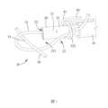
參考圖1以及圖7,其為本發明所提供之打結組成較佳實施例,該打結組成包含一外管10、一內管20、一繫綁線材30以及一保險線材40。該外管10以及該內管20皆為一中空直桿狀,且該內管20可滑動的穿設於該外管10內,該內管20至少一部份突出於該外管10,其中,該內管20軸向的貫穿有一內管通孔22,且突出於該外管10的至少一部份該內管20可以進一步地界定為一套索段21,該套索段21之長短可以透過該內管20相對該外管10之滑動關係調整。Referring to FIGS. 1 and 7 , a preferred embodiment of the knotted assembly provided by the present invention is shown. The knotted assembly includes an
該繫綁線材30軸向地穿設於該內管通孔22內,該繫綁線材30的其中一末端為一繫綁線段31,該繫綁線段31穿出該套索段21方向之該內管通孔22,且該繫綁線段31纏繞該套索段21形成有一預套索32。該預套索32包含形成於該繫綁線段31以及該套索段21之間的一緊束圈321以及纏繞於該套索段21上的一纏繞結322。The
其中,該繫綁線材30的另一末端為一做動線段33,該緊束圈321之大小可以隨著該做動線段33相對該內管20移動而調整;該纏繞結322形成於該套索段21的方式並無限定,本實施例中,該繫綁線段31以一雙圈纏繞後形成一活結的方式於該套索段21上形成該纏繞結322。The other end of the
該保險線材40穿越於至少一部份的該預套索32以及該套索段21之間,且該保險線材40與該預套索32的至少一部份之間呈現相互扣勾的樣態。較佳的,該保險線材40之兩端朝向同一個方向延伸,使得該保險線材40的凹折處形成有一環形結構41,該保險線材40透過該環形結構41與該預套索32的至少一部份相互扣勾。更佳的,該保險線材40之兩端皆朝向該做動線段33之方向延伸,使得該預套索32經由該環形結構41扣勾時,可以保留於該套索段21上靠近該外管10的位置。The
該保險線材40與該預套索32之間相互扣勾的結構關係,該保險線材40得以展現將該預套索32固定於該套索段21上的特性,使得以該活結呈現的該預套索32可以不易於該套索段21上鬆脫或是滑落,進而避免該預套索32在無法預期的狀況下滑脫。The mutual interlocking structural relationship between the
請參考圖1至圖4,該保險線材40扣勾於該預套索32的位置並不限定,如圖1中,該保險線材40穿越該纏繞結322的該雙圈,使得該環形結構41可以扣勾於該雙圈,且該保險線材40之兩端皆朝向該做動線段33之方向延伸,如此該環形結構41便可以固定該雙圈於該套索段21上的相對位置。該保險線材40的設置,不僅是可以達到固定該預套索32的作用,於後續該保險線材40以該環形結構41與該預套索32一起形成為一固定結A時,還可以達到增加該固定結A尺寸之效果,其中,該預套索32形成為該固定結A之步驟以及特徵將進一步於後續詳述。Please refer to FIGS. 1 to 4 . The position where the
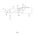
由於該纏繞結322形成於該套索段21的方式並無限定,如圖2本發明所提供之第二較佳實施例中,該繫綁線段31以一參圈纏繞形成該活結的方式於該套索段21上形成該纏繞結322,其中該保險線材40穿越該纏繞結322的該參圈,且該保險線材40之兩端皆朝向該做動線段33之方向延伸,如此該環形結構41便可以固定該參圈於該套索段21上的相對位置。該纏繞結322形成於該套索段21的圈數可以依據所需增加或減少,隨著該纏繞結322纏繞該套索段21的圈數增加,該預套索32於後續形成該固定結A的尺寸也可以隨之增加。There is no limit to the way in which the winding
如圖3,本發明所提供之第三較佳實施例,該繫綁線段31同樣的以該參圈纏繞形成於該套索段21上形成該纏繞結322,於前述不同之處在於,該保險線材40穿越該參圈中位置於一自由端方向的其中一圈,使得該環形結構41僅扣勾位於自由端方向的該其中一圈,如此,其他二圈可以經由該保險線材40以及該其中一圈的抵靠保留於該套索段21上靠近該外管10的位置。由該環形結構41僅與該其中一圈相互扣勾,相較於第二實施例而言,該環形結構41的大小相對較小,於後續形成該固定結A的尺寸也相對的小於上述之第二實施例,使得本發明可以依據一欲打結的位置(如:傷口的部位或是組織的特性)等需求,經由調整該纏繞結322以及該環形結構41展現多樣的打結型態。As shown in FIG. 3 , in the third preferred embodiment provided by the present invention, the tying
如圖4,該保險線材40不僅限於與該纏繞結322相互扣勾,該保險線材40亦可以穿越該緊束圈321的形式存在,本實施例中,該保險線材40形成該環形結構41與該緊束圈321相互扣勾,且該環形結構41位置於該緊束圈321與該纏繞結322連接處,其中,該保險線材40之兩端皆朝向該做動線段33之方向延伸,使得該環形結構41可以抵靠該纏繞結322,並將該纏繞結322保留於該套索段21上靠近該外管10的位置。As shown in Figure 4, the
進一步地,該保險線材40也可以形成一死結於該預套索32的至少一部份,該保險線材40所形成的該死結包含有與該預套索相互扣勾的該環形結構41以及一打結結構,如此,可以確保該保險線材40不會相對該預套索32位移。Furthermore, the
配合參考圖1、圖5至圖7,其為本發明打結組成形成該固定結A之步驟示意圖,包含至少一條打結線材50,該打結線材50穿越該緊束圈321,位置於該緊束圈321內的該打結線材50可以界定為一打結線段51。Referring to Figures 1, 5 to 7, which are schematic diagrams of the steps of forming the fixed knot A according to the knotting composition of the present invention, including at least one
首先,該固定結A欲形成時,拉動位置於該內管20內的該做動線段33,使得該緊束圈321經由該做動線段33收束而逐漸縮小並抵靠至該套索段21前端,此時該打結線段51隨著該緊束圈321的緊束,該打結線段51也一併的抵靠至該套索段21前端或是該套索段21的一外周圍表面。First, when the fixed knot A is to be formed, the moving
隨著該做動線段33持續拉動,該緊束圈321帶動該內管20內相對外管10做動並移入至該外管10內,使得該套索段21之長度逐漸縮短,此時該纏繞結322以及該保險線材40經由該外管10推移,逐漸於該套索段21上朝向該自由端方向移動。需注意的是,該纏繞結322以及該保險線材40朝向該自由端方向移動時,該做動線段33仍是持續拉動,因此該緊束圈321仍保持緊束,而該保險線材40的配置可以防止該纏繞結322於該套索段21移動時提前鬆脫。As the moving
接著,該做動線段33持續拉動,且該外管10持續推移該纏繞結322以及該保險線材40朝向該自由端方向移動,當該纏繞結322以及該保險線材40位置於當該套索段21上該自由端最末端外周圍時,該打結線段51經由緊束抵靠於該外管10該自由端該內管通孔22的開口。進一步地,該保險線材40透過該環形結構41可以將該纏繞結322留置於該內管該自由端最末端位置,可以防止該纏繞結322隨著該做動線段33帶動而掉落至該內管20之內管通孔22中,此特徵可以使得該纏繞結322或是於後續形成的該固定結A不需要限定其大小必需大於該內管20之管口,如此,便可以更加的靈活以及廣泛的使用本案所提供之打結組成。Then, the
最後,當該套索段21完全的收入至該外管10內時,該纏繞結322以及該保險線材40完全脫離該套索段21,此時該纏繞結322內界定有一緊束空間。同時地,該做動線段33持續拉動,使得該束套圈22拉動該打結線段51反折形成一緊束環結構511深入該緊束空間,該纏繞結322經由該做動線段33持續拉動,使得該預套索32緊束該打結線段51以及該保險線材40形成該固定結A。Finally, when the
當該套索段21完全的收入至該外管10內時,當該固定結A之尺寸大於該外管10該自由端的一開口,可以避免該固定結A形成時陷入該外管10的該開口,且該外管10也可以產生一抵靠作用,使得該固定結A形成時可以經由該外管10前端抵靠於欲打結的位置,進一步地達到防止該纏繞結322以及該保險線材40在脫離該套索段21的瞬間位移,避免該固定結A形成於不理想的位置。希望新增When the
本發明所提供之打結組成在該固定結A後,由於包含了該纏繞結322、該保險線材40以及緊束環結構511互相纏繞於其中,使得的彼此間接觸面增加,進一步的增加了該固定結A整體摩擦力,可以更佳的預防該固定結A鬆脫,尤其是應用於一單股線材上。另外的,也可以在該固定結A欲形成時,先將該保險線材40至該預套索32以及該套索段21之間抽離,如此,便可以依據需求縮小該固定結A形成後之尺寸。After the fixed knot A, the knotting composition provided by the present invention includes the winding
本發明透過該保險線材固定該預套索,無須設置其他的一固定結構,使得本發明所提供之打結組成可以將整體體積設計至最小,也由於省略了該固定結構,使得管狀的該內管以及該外管可以是一軟質材料所形成,使得該打結組成可以適應於複雜以及狹小的空間中,有助於微創手術的使用與進步。The present invention fixes the pre-lasso through the insurance wire, without the need to provide another fixing structure, so that the knotting composition provided by the present invention can design the overall volume to a minimum, and because the fixing structure is omitted, the tubular inner The tube and the outer tube can be made of a soft material, so that the knotted composition can be adapted to complex and narrow spaces, which is helpful for the use and advancement of minimally invasive surgery.
本發明中,該繫綁線材30、該保險線材40以及該打結線材50並不限為相同類型或尺寸的線材,該繫綁線材30、該保險線材40以及該打結線材50亦不限定為手術縫合線,一使用者可以依據所需選擇該繫綁線材30、該保險線材40以及該打結線材50之大小、該纏繞結322形成於該套索段21的圈數、該保險線材40扣勾於該預套索32的位置以及該打結線材50穿入該緊束圈321的數量,進一步的調整該固定結A的尺寸,使的本發明極具應用性。另外,該繫綁線材30、該保險線材40以及該打結線材50並不限定為三條分開之線材,某些實施例上,該繫綁線材30與該保險線材40可以是相互連接的同一條線材,該繫綁線材30也可以與該打結線材50為相互連接的同一條線材,又或是該保險線材40與該打結線材50為相互連接的同一條線材。In the present invention, the binding
本發明所提供之打結組成,並無限定用於特定領域。舉例本發明應用於一醫療領域時,一手術人員可以利用該打結線材50於一傷口完成縫合時,該手術人員可以將該打結線材50穿越該打結組成的該緊束圈321,此時該手術人員可以該打結組成的該套索段21位移至一傷口縫合附近,隨著該做動線段33拉動,當該套索段21完全的收入至該外管10內時,該手術人員可以將該纏繞結322抵靠於該傷口縫合處,使得該固定結A形成時可以完善的位置於該傷口縫合處,達到良好的打結效果。The knotting composition provided by the present invention is not limited to specific fields. For example, when the present invention is applied to a medical field, an operator can use the knotted
10:外管10:Outer tube
20:內管20:Inner tube
21:套索段21: Lasso segment
22:內管通孔22: Inner tube through hole
30:繫綁線材30: Tying wires
31:繫綁線段31: Tying line segments
32:預套索32: Pre-lasso
321:緊束圈321: tight ring
322:纏繞結322:Tangle knot
33:做動線段33: Make moving line segments
40:保險線材40:Insurance wire
41:環形結構41: Ring structure
50:打結線材50: Knotted wire
51:打結線段51: Knotted line segments
Claims (10)
Translated fromChinesePriority Applications (1)
| Application Number | Priority Date | Filing Date | Title |
|---|---|---|---|
| TW110143083ATWI824339B (en) | 2021-11-19 | 2021-11-19 | A knotting assembly |
Applications Claiming Priority (1)
| Application Number | Priority Date | Filing Date | Title |
|---|---|---|---|
| TW110143083ATWI824339B (en) | 2021-11-19 | 2021-11-19 | A knotting assembly |
Publications (2)
| Publication Number | Publication Date |
|---|---|
| TW202320713A TW202320713A (en) | 2023-06-01 |
| TWI824339Btrue TWI824339B (en) | 2023-12-01 |
Family
ID=87803931
Family Applications (1)
| Application Number | Title | Priority Date | Filing Date |
|---|---|---|---|
| TW110143083ATWI824339B (en) | 2021-11-19 | 2021-11-19 | A knotting assembly |
Country Status (1)
| Country | Link |
|---|---|
| TW (1) | TWI824339B (en) |
Citations (2)
| Publication number | Priority date | Publication date | Assignee | Title |
|---|---|---|---|---|
| US5749898A (en)* | 1997-04-08 | 1998-05-12 | Ethicon Endo-Surgery, Inc. | Suture cartridge assembly for a surgical knot |
| CN209499798U (en)* | 2018-12-06 | 2019-10-18 | 中国医科大学附属第一医院 | A kind of surgical stapling surgical instrument |
- 2021
- 2021-11-19TWTW110143083Apatent/TWI824339B/enactive
Patent Citations (2)
| Publication number | Priority date | Publication date | Assignee | Title |
|---|---|---|---|---|
| US5749898A (en)* | 1997-04-08 | 1998-05-12 | Ethicon Endo-Surgery, Inc. | Suture cartridge assembly for a surgical knot |
| CN209499798U (en)* | 2018-12-06 | 2019-10-18 | 中国医科大学附属第一医院 | A kind of surgical stapling surgical instrument |
Also Published As
| Publication number | Publication date |
|---|---|
| TW202320713A (en) | 2023-06-01 |
Similar Documents
| Publication | Publication Date | Title |
|---|---|---|
| US11918199B2 (en) | Method for intra-abdominally moving an organ | |
| US8317827B2 (en) | Suturing devices and methods | |
| US8888679B2 (en) | Apparatus and method for intra-abdominally moving a first internal organ to a position away from a second internal organ and the holding the first internal organ in the position without manual input | |
| US10327763B2 (en) | Knotless collapsible sutures and methods for suturing | |
| JP2009511178A (en) | Helical retainer, tool and method for using a helical retainer | |
| US20120158051A1 (en) | Re-tensionable knotless suture system | |
| KR102517521B1 (en) | Locking suture construct | |
| JP6231111B2 (en) | Method and device for approaching tissue | |
| JP6979351B2 (en) | Equipment and methods for tying knots | |
| TWI824339B (en) | A knotting assembly | |
| US10828024B2 (en) | Ligation device | |
| WO2023087294A1 (en) | Knotting assembly | |
| US11712238B2 (en) | Device and method for intracorporeal and extracorporeal laparoscopic suturing and knot tying | |
| TWI888294B (en) | Tubular knotting device | |
| US11622760B2 (en) | Knotting assembly for surgical suture line | |
| JP2023032540A (en) | Tape for organ ligature | |
| TW202410865A (en) | Capsule suture module | |
| JP2003265486A (en) | Ligation aid |