TWI819902B - Wireless power transfer device and system - Google Patents
Wireless power transfer device and systemDownload PDFInfo
- Publication number
- TWI819902B TWI819902BTW111144398ATW111144398ATWI819902BTW I819902 BTWI819902 BTW I819902BTW 111144398 ATW111144398 ATW 111144398ATW 111144398 ATW111144398 ATW 111144398ATW I819902 BTWI819902 BTW I819902B
- Authority
- TW
- Taiwan
- Prior art keywords
- capacitor
- coil
- transmission
- wireless charging
- capacitance value
- Prior art date
Links
- 238000012546transferMethods0.000titledescription2
- 239000003990capacitorSubstances0.000claimsabstractdescription124
- 230000005540biological transmissionEffects0.000claimsdescription132
- 230000008859changeEffects0.000claimsdescription7
- 230000010355oscillationEffects0.000claimsdescription4
- 238000010586diagramMethods0.000description19
- 230000014509gene expressionEffects0.000description7
- 229910000859α-FeInorganic materials0.000description5
- 230000003071parasitic effectEffects0.000description4
- 238000005516engineering processMethods0.000description3
- 238000006243chemical reactionMethods0.000description2
- 238000002474experimental methodMethods0.000description2
- 230000006698inductionEffects0.000description2
- 238000000034methodMethods0.000description2
- 238000005457optimizationMethods0.000description2
- 238000012545processingMethods0.000description2
- 230000003068static effectEffects0.000description2
- 238000004804windingMethods0.000description2
- 230000004913activationEffects0.000description1
- 238000005452bendingMethods0.000description1
- 230000000694effectsEffects0.000description1
- 238000005259measurementMethods0.000description1
- 238000012986modificationMethods0.000description1
- 230000004048modificationEffects0.000description1
- 230000035699permeabilityEffects0.000description1
- 230000008569processEffects0.000description1
Images


Landscapes
- Charge And Discharge Circuits For Batteries Or The Like (AREA)
Abstract
Description
Translated fromChinese本發明係關於一種無線充電裝置及系統,特別是關於一種適用於移動載具的無線充電裝置及系統。The present invention relates to a wireless charging device and system, and in particular to a wireless charging device and system suitable for mobile vehicles.
一般來說,無線充電技術可分為靜態無線充電技術或動態無線充電(Dynamic Wireless Power Transfer,DWPT)技術。實施靜態無線充電時,需要將待充物以特定方向及距離靠近充電物,並等待一定時間;而對於動態無線充電而言,充電物可隨著待充物的移動調控內部的充電電路以實時進行充電工作。Generally speaking, wireless charging technology can be divided into static wireless charging technology or dynamic wireless charging (Dynamic Wireless Power Transfer, DWPT) technology. When implementing static wireless charging, you need to bring the object to be charged close to the charging object in a specific direction and distance and wait for a certain period of time; for dynamic wireless charging, the charging object can adjust the internal charging circuit in real time as the object to be charged moves. Carry out charging work.
動態無線充電目前仍具有諸多限制,舉例來說,充電線圈需要沿直線設置。然而考量到許多彎曲軌道上的實際需求(如一般道路),直線架構的無線充電系統的各式參數將不符合彎道上的應用,造成其充電效率不佳或是較不穩定。Dynamic wireless charging still has many limitations. For example, the charging coil needs to be placed in a straight line. However, considering the actual needs on many curved tracks (such as ordinary roads), the various parameters of a linear wireless charging system will not meet the application on curves, resulting in poor charging efficiency or instability.
鑒於上述,本發明提供一種無線充電裝置及系統。In view of the above, the present invention provides a wireless charging device and system.
依據本發明一實施例的無線充電裝置,包含第一線圈、第一電容、第二電容以及第一電感。第一線圈具有一曲率半徑及關聯於該曲率半徑的電感值,用於將一交流電訊號轉換為磁場。第一電容的一端連接於第一線圈的一端。第二電容的一端連接於第一電容的另一端,且另一端連接於第一線圈的另一端。第一電感的一端連接於第一電容的另一端及第二電容的一端,且另一端用於接收所述交流電訊號。第一電容的電容值及第二電容的電容值中的至少一者由所述第一線圈的電感值決定。A wireless charging device according to an embodiment of the present invention includes a first coil, a first capacitor, a second capacitor and a first inductor. The first coil has a radius of curvature and an inductance value associated with the radius of curvature, and is used to convert an alternating current signal into a magnetic field. One end of the first capacitorConnected to one end of the first coil. One end of the second capacitor is connected to the other end of the first capacitor, and the other end is connected to the other end of the first coil. One end of the first inductor is connected to the other end of the first capacitor and one end of the second capacitor, and the other end is used to receive the alternating current signal. At least one of the capacitance value of the first capacitor and the capacitance value of the second capacitor is determined by the inductance value of the first coil.
依據本發明一實施例的動態無線充電系統,包含多個傳輸線圈、一接收線圈以及一補償電容。所述多個傳輸線圈的每一者具有一曲率半徑及關聯於所述曲率半徑的電感值,且各用於將一交流電訊號轉換為磁場。所述多個補償電路各包含第一電容、第二電容及第一電感,其中第一電容之一端連接於所述多個傳輸線圈中的一者的一端;第二電容的之一端連接於第一電容的另一端,且以另一端連接於所述傳輸線圈的另一端;第一電感之一端連接於第一電容的另一端及第二電容的一端,且另一端用於接收所述交流電訊號。接收線圈用於將所述多個傳輸線圈中的至少二者各自產生的磁場轉換為另一交流電訊號,且一端用於連接至一負載。第一電容的電容值及第二電容的電容值中的至少一者由所述傳輸線圈的電感值決定。A dynamic wireless charging system according to an embodiment of the present invention includes multiple transmission coils, a receiving coil and a compensation capacitor. Each of the plurality of transmission coils has a radius of curvature and an inductance value associated with the radius of curvature, and is each used to convert an alternating current signal into a magnetic field. Each of the plurality of compensation circuits includes a first capacitor, a second capacitor and a first inductor, wherein one end of the first capacitor is connected to one end of one of the plurality of transmission coils; one end of the second capacitor is connected to the The other end of a capacitor is connected to the other end of the transmission coil; one end of the first inductor is connected to the other end of the first capacitor and one end of the second capacitor, and the other end is used to receive the alternating current signal. . The receiving coil is used to convert the magnetic field generated by at least two of the plurality of transmitting coils into another alternating current signal, and one end is used to be connected to a load. At least one of the capacitance value of the first capacitor and the capacitance value of the second capacitor is determined by the inductance value of the transmission coil.
藉由上述結構,本案所揭示的無線充電裝置及系統可透過使用補償電路,確保系統中電壓與電流同相,使系統成為純電阻性,減少傳輸時的損耗,藉此增加傳輸效率。傳輸線圈可依據應用需求而具有一彎曲結構(伴隨著一曲率半徑),所述補償電路中的電容的配置是依據傳輸線圈的電感值而定,而傳輸線圈的電感值隨著所述曲率半徑而變化。如此一來,可隨著傳輸線圈的曲率半徑調整補償電路中的電容配置,提供適用於彎道的無線充電裝置及系統,達成整體傳輸效率的優化。With the above structure, the wireless charging device and system disclosed in this case can ensure that the voltage and current in the system are in phase by using a compensation circuit, making the system purely resistive, reducing transmission losses, thereby increasing transmission efficiency. The transmission coil can have a curved structure (accompanied by a radius of curvature) according to application requirements. The configuration of the capacitor in the compensation circuit is based on the inductance value of the transmission coil, and the inductance value of the transmission coil changes with the radius of curvature. And changechange. In this way, the capacitor configuration in the compensation circuit can be adjusted according to the curvature radius of the transmission coil, providing a wireless charging device and system suitable for curves, thereby optimizing the overall transmission efficiency.
以上之關於本揭露內容之說明及以下之實施方式之說明係用以示範與解釋本發明之精神與原理,並且提供本發明之專利申請範圍更進一步之解釋。The above description of the present disclosure and the following description of the embodiments are used to demonstrate and explain the spirit and principles of the present invention, and to provide further explanation of the patent application scope of the present invention.
1,1’:無線充電裝置1,1’: Wireless charging device
10,10A,10B:第一線圈10,10A,10B: first coil
10_1,10_2,10_3,10_4,10_n:傳輸線圈10_1,10_2,10_3,10_4,10_n:Transmission coil
12:第一電容12: First capacitor
12_1,12_2,12_n:電容12_1,12_2,12_n: capacitor
14:第二電容14: Second capacitor
14_1,14_2,14_n:電容14_1,14_2,14_n: capacitor
15:處理器15: Processor
16:第一電感16: First inductor
16_1,16_2,16_n:電感16_1,16_2,16_n: inductor
18_1,18_2,18_n:開關元件18_1,18_2,18_n: switching elements
19_1,19_2,19_n:電流感測器19_1,19_2,19_n:Current sensor
20:接收線圈20:Receive coil
22:補償電容22: Compensation capacitor
5:無線充電系統5:Wireless charging system
AC:交流電源供應器AC: AC power supply
C1,C2,Cn:補償電路C1, C2, Cn: compensation circuit
d1,d2:間距d1,d2: spacing
Fe:鐵氧體層Fe:ferrite layer
N1,N2:端N1, N2: end
O:虛圓心O: center of virtual circle
RL:負載RL : load
r1,r2,r3:曲率半徑r1, r2, r3: radius of curvature
ra:線圈寬度ra: coil width
w:寬度w:width
θ1,θ2,θ3:角度θ1, θ2, θ3: angle
D1,D2,D3:實驗數據D1, D2, D3: experimental data
圖1係依據本發明一實施例所繪示的無線充電裝置的電路圖。FIG. 1 is a circuit diagram of a wireless charging device according to an embodiment of the present invention.
圖2A係依據本發明一實施例所繪示的無線充電裝置的傳輸線圈的一實施態樣的示意圖。FIG. 2A is a schematic diagram of an implementation of a transmission coil of a wireless charging device according to an embodiment of the present invention.
圖2B係依據本發明一實施例所繪示的無線充電裝置的傳輸線圈的另一實施態樣的示意圖。FIG. 2B is a schematic diagram of another implementation of the transmission coil of the wireless charging device according to an embodiment of the present invention.
圖3係依據本發明另一實施例所繪示的無線充電裝置的電路圖。FIG. 3 is a circuit diagram of a wireless charging device according to another embodiment of the present invention.
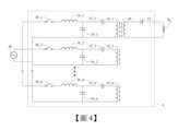
圖4係依據本發明一實施例所繪示的動態無線充電系統的電路圖。FIG. 4 is a circuit diagram of a dynamic wireless charging system according to an embodiment of the present invention.
圖5A係依據本發明一實施例所繪示的動態無線充電系統的多個傳輸線圈的排列示意圖。FIG. 5A is a schematic diagram of the arrangement of multiple transmission coils of a dynamic wireless charging system according to an embodiment of the present invention.
圖5B係依據本發明一實施例所繪示的動態無線充電系統的接收線圈的示意圖。FIG. 5B is a schematic diagram of a receiving coil of a dynamic wireless charging system according to an embodiment of the present invention.
圖6係依據本發明另一實施例所繪示的動態無線充電系統的功能方塊圖。FIG. 6 is a functional block diagram of a dynamic wireless charging system according to another embodiment of the present invention.
圖7係依據本發明另一實施例所繪示的動態無線充電系統在不同實施態樣下的傳輸效率圖表。FIG. 7 is a diagram illustrating the transmission efficiency of a dynamic wireless charging system under different implementation aspects according to another embodiment of the present invention.
以下在實施方式中詳細敘述本發明之詳細特徵以及優點,其內容足以使任何熟習相關技藝者了解本發明之技術內容並據以實施,且根據本說明書所揭露之內容、申請專利範圍及圖式,任何熟習相關技藝者可輕易地理解本發明相關之目的及優點。以下之實施例係進一步詳細說明本發明之觀點,但非以任何觀點限制本發明之範疇。The detailed features and advantages of the present invention are described in detail below in the implementation mode. The content is sufficient to enable anyone skilled in the relevant art to understand the technical content of the present invention and implement it according to the content disclosed in this specification, the patent scope and the drawings. , anyone familiar with the relevant art can easily understand the relevant objectives and advantages of the present invention. The following examples further illustrate the aspects of the present invention in detail, but do not limit the scope of the present invention in any way.
請參考圖1,圖1為依據本發明一實施例所繪示的無線充電裝置的電路圖。如圖1所示,無線充電裝置1包含第一線圈10、第一電容12、第二電容14及第一電感16。第一線圈10具有一電感值Ltp,且用於將一交流電源供應器AC提供的交流電訊號轉換為磁場。第一電容12之一端連接於第一線圈10的一端N1。第二電容14的一端連接於第一電容12的另一端,且另一端連接於第一線圈10的另一端N2。第一電感16的一端連接於第一電容12的另一端及第二電容14的一端,且另一端用於接收所述交流電訊號。第一電容12的電容值Ctp及第二電容14的電容值Cts中的至少一者由所述第一線圈的電感值Ltp決定。Please refer to FIG. 1 , which is a circuit diagram of a wireless charging device according to an embodiment of the present invention. As shown in FIG. 1 , the
在本例中,交流電源供應器AC用於提供交流電訊號。在其他實施例中,交流電源供應器AC可由其他方式實現,例如一直流電源供應器搭配一逆變器(DC/AC converter),本案不限於此。第一線圈10可為導線環繞多圈形成的線圈,且如具備本領域通常知識者能理解的,環形導線具有電感效應因而具有電感值。特別來說,第一線圈10的電感值Ltp可由以下因素決定:線圈面積(A)、環繞圈數(N)及環繞圈數密度(L/N),即
另一方面,無線充電裝置1的傳輸效率可根據第一電容12、第二電容14以及第一電感16組成的補償電路決定。具體來說,本例的補償電路的第一電容12的電容值Ctp及第二電容14的電容值Cts可由第一線圈的電感值Ltp決定。請參考下列關係式1。On the other hand, the transmission efficiency of the

上述關係式中的ω為該交流電訊號之振盪角頻率。透過關係式1可以適當調整對應的第一電容12的電容值Ctp及第二電容14的電容值Cts。此外,若將第一電感的電感值Lts納入考量,可參考下列關係式2。ω in the above relationship is the oscillation angular frequency of the AC signal. The corresponding capacitance value Ctp of the

當第一電容12的電容值Ctp、第二電容14的電容值Cts及第一電感的電感值Lts滿足上述關係式1及2時,無線充電裝置1可視為一諧振電路(Resonant Circuit),也就是電流與電壓的相位一致,因而使阻抗(impedance)最低而具有較佳的傳輸效率。When the capacitance value Ctp of the
請結合圖1參照圖2A及圖2B,圖2A係依據本發明一實施例所繪示的無線充電裝置的傳輸線圈的一實施態樣的示意圖,圖2B係依據本發明一實施例所繪示的無線充電裝置的傳輸線圈的另一實施態樣的示意圖。如圖2A所示,第一線圈10A為一種Q型線圈,可具有一彎曲結構以及對應於彎曲結構的一曲率半徑r1或r2(以第一線圈10A兩邊的虛擬延伸線相交處為一虛圓心O)。如上所述的,第一線圈10A的電感值Ltp可由線圈面積、環繞圈數及環繞圈數密度決定,也就是說,第一線圈10A的電感值Ltp可關聯於曲率半徑r1及r2。第一線圈的另一實施態樣如圖2B所示,第一線圈10B為一種DD型線圈,可具有一彎曲結構以及對應於彎曲結構的一曲率半徑r1、r2或r3(以第一線圈10B兩邊的虛擬延伸線相交處為一虛圓心O),且第一線圈10B的電感值Ltp也可關聯於曲率半徑r1、r2及r3,在此不贅述。需要注意的是,第一線圈10A與10B的彎曲程度可具有多種描述方式,本案不限於此。具體來說,除了上述的曲率半徑r1、r2及r3以外,也可將曲率半徑進行運算(如算術平均或幾何平均),或是透過角度對彎曲程度進行定義。此外,上述的交流電訊號可由線圈的一端N1及另一端N2輸入至線圈以產生磁場,且由於交流電訊號本身隨時間變換電流方向,故兩端N1及N2並沒有輸入端與輸出端的差異。需要注意的是,DD型線圈(第一線圈10B)的上下兩半部的電流傳遞方向相反,此部分於後面詳述。Please refer to FIGS. 2A and 2B in conjunction with FIG. 1 . FIG. 2A is a schematic diagram of a transmission coil of a wireless charging device according to an embodiment of the present invention. FIG. 2B is a schematic diagram of a transmission coil according to an embodiment of the present invention. A schematic diagram of another embodiment of the transmission coil of the wireless charging device. As shown in FIG. 2A , the
除了圖2A及圖2B所示的Q型線圈及DD型線圈以外,本案不限制其他實施態樣中採用不同形狀的線圈。舉例來說,將上述的DD型線圈的兩半部錯位重疊以在中間形成另一環狀空間的線圈,也可能作為本案線圈的一種實施態樣,在此不予以限制。請參照圖3,圖3為依據本發明另一實施例所繪示的無線充電裝置的電路圖。如圖3所示,無線充電裝置1’的第一傳輸線圈10_1、第一電容12_1、第二電容14_1及第一電感16_1分別與圖1所示的第一線圈10、第一電容12、第二電容14及第一電感16相同,在此省略重複敘述。本例更包含第二傳輸線圈10_2、第三電容12_2、第四電容14_2及第二電感16_2,並聯於圖1所示的元件。類似地,第二傳輸線圈10_2具有一曲率半徑及關聯於該曲率半徑的一電感值Ltp,且用於將交流電訊號轉換為磁場。第三電容12_2之一端連接於第二傳輸線圈10_2的一端。第四電容14_2之一端連接於第三電容12_2的另一端。第二電感16_2之一端連接於第三電容12_2的另一端及第四電容14_2的一端,且第二電感16_2的另一端用於接收交流電訊號。第三電容12_2的電容值Ctp及第四電容14_2的電容值Cts中的至少一者取決於第二傳輸線圈10_2的電感值Ltp,其中第一傳輸線圈10_1為一Q型線圈,第二傳輸線圈10_2為一DD型線圈。In addition to the Q-shaped coil and the DD-shaped coil shown in FIGS. 2A and 2B , this case does not limit the use of coils of different shapes in other implementations. For example, a coil in which the two halves of the above-mentioned DD-type coil are staggered and overlapped to form another annular space in the middle may also be used as an implementation mode of the coil of this invention, and is not limited here. Please refer to FIG. 3 , which is a circuit diagram of a wireless charging device according to another embodiment of the present invention. As shown in Figure 3, the first transmission coil 10_1, the first capacitor 12_1, the second capacitor 14_1 and the first inductor 16_1 of the wireless charging device 1' are respectively connected with the
另外,本例的無線充電裝置1’更選擇性設有兩開關元件18_1及18_2,分別連接於第一電感16_1的另一端及第二電感16_2的另一端,且分別用於將交流電訊號導通至第一傳輸線圈10_1及第二傳輸線圈10_2,或使交流電訊號不被傳輸至第一傳輸線圈10_1及第二傳輸線圈10_2。本例的第一傳輸線圈10_1與第二傳輸線圈10_2在空間上彼此靠近排列,且在開關元件18_1及18_2皆導通的情形下,Q型線圈與DD型線圈各自的磁場對彼此產生的感應電流相較於交流電源供應器AC提供的交流電訊號可忽略不計。請結合參考圖2B,DD型線圈的上半部與下半部的繞線方向相反,使得DD型線圈的上半部與下半部產生的磁場方向相反,因此在Q型線圈上產生的感應電流可互相抵消(換言之,Q型線圈於DD型線圈上半部及下半部產生的感應電流同理可互相抵消)。In addition, the wireless charging device 1' of this example is further selectively provided with two switching elements 18_1 and 18_2, which are respectively connected to the other end of the first inductor 16_1 and the other end of the second inductor 16_2, and are respectively used to conduct the AC signal to The first transmission coil 10_1 and the second transmission coil 10_2 may prevent the AC signal from being transmitted to the first transmission coil 10_1 and the second transmission coil 10_2. In this example, the first transmission coil 10_1 and the second transmission coil 10_2 are spatially arranged close to each other, and when the switching elements 18_1 and 18_2 are both turned on, the magnetic fields of the Q-type coil and the DD-type coil generate induced currents for each other. Compared with the AC power supply, the AC signal provided by AC is negligible. Please refer to Figure 2B. The winding directions of the upper half and the lower half of the DD-type coil are opposite, so that the magnetic fields generated by the upper and lower half of the DD-type coil are in opposite directions. Therefore, the induction generated on the Q-type coil The currents can cancel each other out (in other words, the induced currents generated by the Q-type coil in the upper and lower parts of the DD-type coil can cancel each other out in the same way).
在本例中,開關元件18_1及18_2的控制可依據待充電裝置與傳輸線圈10_1及10_2的相對位置而定。舉例來說,當待充電裝置靠近傳輸線圈10_1且遠離傳輸線圈10_2時,開關元件18_1可被導通且開關元件18_2可被關斷;當待充電裝置靠近傳輸線圈10_2且遠離傳輸線圈10_1時,開關元件18_2可被導通且開關元件18_1可被關斷;當待充電裝置靠近傳輸線圈10_1及10_2時,開關元件18_1及18_2可皆被導通;當待充電裝置遠離傳輸線圈10_1及10_2時,開關元件18_1及18_2可皆被關斷。在上述情形中,當開關元件18_1及18_2皆被導通時,相鄰設置的第一傳輸線圈(Q型線圈)10_1與第二傳輸線圈(DD型線圈)10_2也可不彼此影響而保持傳輸效率。具體來說,待充電裝置上可設有定位元件,定位元件可訊號連接至無線充電裝置1’的一控制器,且開關元件可連接至該控制器並受其控制。In this example, the control of the switching elements 18_1 and 18_2 may be based on the relative positions of the device to be charged and the transmission coils 10_1 and 10_2. For example, when the device to be charged is close to the transmission coil 10_1 and far away from the transmission coil 10_2, the switching element 18_1 can be turned on and the switching element 18_2 can be turned off; when the device to be charged is close to the transmission coil 10_2 and far away from the transmission coil 10_1, the switch The element 18_2 can be turned on and the switching element 18_1 can be turned off; when the device to be charged is close to the transmission coils 10_1 and 10_2, the switching elements 18_1 and 18_2 can both be turned on; when the device to be charged is far away from the transmission coils 10_1 and 10_2, the switching element 18_1 and 18_2 can both be turned off. In the above situation, when the switching elements 18_1 and 18_2 are both turned on, the adjacently arranged first transmission coil (Q-type coil) 10_1 and the second transmission coil (DD-type coil) 10_2 can maintain transmission efficiency without affecting each other. Specifically, the device to be charged can be provided with a positioning element, the positioning element can be signal-connected to a controller of the wireless charging device 1', and the switching element can be connected to and controlled by the controller.
請參照圖4,圖4係依據本發明一實施例所繪示的動態無線充電系統的電路圖。如圖4所示,動態無線充電系統5包含多個傳輸線圈(10_1、10_2至10_n)、多個補償電路、一接收線圈20以及一補償電容22。每個傳輸線圈具有一曲率半徑及關聯於該曲率半徑的一電感值,且用於將一交流電訊號轉換為磁場。補償電路包含第一電容(12_1、12_2至12_n)、第二電容(14_1、14_2至14_n)及第一電感(16_1、16_2至16_n)。第一電容之一端連接於第一線圈的一端。第二電容的一端連接於第一電容的另一端,且另一端連接於第一線圈的另一端。第一電感的一端連接於第一電容的另一端及第二電容的一端,且另一端用於接收所述交流電訊號。第一電容的電容值及第二電容的電容值中的至少一者由所述第一線圈的電感值決定。接收線圈20用於將傳輸線圈中的至少二者各自產生的磁場轉換為另一交流電訊號,且一端用於連接於一負載RL。補償電容22之一端連接於接收線圈20且另一端用於連接於負載RL。以下為了避免重複敘述,於本例將帶過對應於圖1至圖3且與傳輸線圈相關的細節。Please refer to FIG. 4 , which is a circuit diagram of a dynamic wireless charging system according to an embodiment of the present invention. As shown in FIG. 4 , the dynamic
進一步,本例的每個第一電容的電容值Ctp及第二電容的電容值Cts可由傳輸線圈的電感值Ltp決定,請參考關係式1。而第一電感的電感值Lts可由第二電容的電容值Cts決定,請參考關係式2。另外,接收線圈20的電感值Lr以及補償電容22的電容值Cr可依照下列關係式3進行設計。Furthermore, in this example, the capacitance value Ctp of each first capacitor and the capacitance value Cts of the second capacitor can be determined by the inductance value Ltp of the transmission coil. Please refer to the


上述關係式中的ω為該交流電訊號之振盪角頻率。當第一電容的電容值Ctp、第二電容14的電容值Cts及第一電感的電感值Lts滿足上述關係式時,系統的無線充電裝置可視為一諧振電路(Resonant Circuit),也就是電流與電壓的相位一致,因而使阻抗(impedance)最低而具有最佳的傳輸效率。另一方面當接收線圈20的電感值Lr以及補償電容22的電容值Cr滿足關係式3時,接收線圈20與補償電容22亦達成諧振條件,具有較高的接收效率。透過上述的無線充電系統5,交流電源供應器AC可並聯至所述多個傳輸線圈,並透過磁場變化將能量傳輸給接收線圈20。需要注意的是,在接收線圈20接受磁場變化後,會產生相應的感應交流電並透過補償電容22後施加於一負載RL;而在其他實施態樣中,感應交流電可透過一整流器(Rectifier)被轉換為一直流電再施加於負載RL;此外也可以額外並聯設置一個濾波電容,以減少閃頻訊號對負載RL的影響。ω in the above relationship is the oscillation angular frequency of the AC signal. When the capacitance value Ctp of the first capacitor, the capacitance value Cts of the
請結合圖4參考圖5A及圖5B,圖5A係依據本發明一實施例所繪示的動態無線充電系統的多個傳輸線圈的排列示意圖,圖5B係依據本發明一實施例所繪示的動態無線充電系統的接收線圈的示意圖。如圖5A所示,傳輸線圈10_1及10_3為Q型線圈,傳輸線圈10_2及10_4為DD型線圈,且彼此為交錯排列。本例的傳輸線圈設置在鐵氧體層Fe上,以避免磁場發散造成能量損耗。在本例中,每個傳輸線圈相對於圓心佔有的旋轉角度θ1為18°,傳輸線圈的內緣曲率半徑r1(相對於虛圓心O)為160毫米(mm),外緣的曲率半徑r2為263.75毫米,線圈寬度ra為103.75毫米,線圈線寬w為13.8毫米,鐵氧體邊界的寬度d1為10毫米。Please refer to FIGS. 5A and 5B in conjunction with FIG. 4 . FIG. 5A is a schematic diagram of the arrangement of multiple transmission coils of a dynamic wireless charging system according to an embodiment of the present invention. FIG. 5B is a schematic diagram of a plurality of transmission coils according to an embodiment of the present invention. Schematic diagram of the receiving coil of a dynamic wireless charging system. As shown in FIG. 5A , the transmission coils 10_1 and 10_3 are Q-shaped coils, and the transmission coils 10_2 and 10_4 are DD-shaped coils, and are arranged in a staggered manner. The transmission coil in this example is set on the ferrite layer Fe to avoid energy loss caused by magnetic field divergence. In this example, the rotation angle θ1 occupied by each transmission coil relative to the center of the circle is 18°, the radius of curvature r1 of the inner edge of the transmission coil (relative to the virtual center O) is 160 millimeters (mm), and the radius of curvature r2 of the outer edge is 263.75 mm, the coil width ra is 103.75 mm, the coil line width w is 13.8 mm, and the width of the ferrite boundary d1 is 10 mm.
如圖5B所示,接收線圈20為一DDQ型串聯線圈,即包含一Q型線圈串聯一DD型線圈的結構。在本例中,接收線圈20的Q型線圈部分的張角θ2為41.5°,DD型線圈部分的張角為38.5°,換言之,接收線圈20可在旋轉角度θ1的方向上涵蓋一個Q型線圈及一個DD型線圈(38.5°>2×18°);然而在其他實施態樣中,接收線圈20的張角可被設為傳輸線圈的旋轉角度θ1的三倍如54°,使得接收線圈無論在何種情形下都能確保涵蓋至少一個Q型傳輸線圈及一個DD型傳輸線圈。本例的接收線圈20同樣設置在鐵氧體層(未標號)上以避免磁場發散,且鐵氧體邊界的寬度d2為10毫米。此外,接收線圈20的線圈寬度(圖未示)可大於或等於傳輸線圈的線圈寬度ra,使得接收線圈20能充分接收來自傳輸線圈產生的磁場。As shown in FIG. 5B , the receiving
請結合圖4及圖5參考圖6,圖6為依據本發明另一實施例所繪示的動態無線充電系統的功能方塊圖。無線充電系統5可更包含多個開關元件(18_1、18_2至18_n),所述多個開關元件中的每一者連接於多個補償電路(C1、C2至Cn)中的一對應者的第一電感(16_1、16_2至16_n)的另一端,且用於使所述交流電訊號導通至傳輸線圈(10_1、10_2至10_n),或使所述交流電訊號不被導通至傳輸線圈中的所述對應者。為了便於理解,圖4至圖6的傳輸線圈以相同符號標記,例如圖4、圖5A及圖6的傳輸線圈10_1可互相對應,其餘元件以此類推。在一種實施態樣中,開關元件可根據接收線圈20與多個傳輸線圈(10_1、10_2至10_n)的相對位置被控制。舉例來說,當系統偵測到接收線圈接近傳輸線圈10_1時,可控制對應的開關元件18_1使交流電訊號導通至傳輸線圈10_1。在另一實施態樣中,無線充電系統5更可包含多個電流感測器(19_1、19_2至19_n)及一處理器。如圖6所示,所述多個電流感測器分別連接於補償電路(C1、C2至Cn),所述多個電流感測器中的每一者用於感測補償電路(C1、C2至Cn)中的一對應者的一電流。處理器15連接於電流感測器(19_1、19_2至19_n)及開關元件(18_1、18_2至18_n),用於在判斷補償電路中的第一補償電路的電流的變化量大於一預設值且補償電路中的至少一第二補償電路的電流大於零時,控制開關元件中與第一補償電路連接的一第一開關元件為一關斷狀態,並控制該些開關元件中的一第二開關元件為一導通狀態,其中傳輸線圈中對應於第一開關元件的一第一傳輸線圈、對應於所述至少一第二補償電路的至少一第二傳輸線圈以及對應於第二開關元件的一第三傳輸線圈依序相鄰排列。Please refer to FIG. 6 in conjunction with FIG. 4 and FIG. 5 . FIG. 6 is a functional block diagram of a dynamic wireless charging system according to another embodiment of the present invention. The
具體來說,圖5A中所示的傳輸線圈10_1為第一傳輸線圈10_1,傳輸線圈10_2及10_3為兩第二傳輸線圈10_2及10_3,傳輸線圈10_4為第三傳輸線圈10_4。當處理器15根據第一電流感測器19_1的量測判斷對應於第一傳輸線圈10_1的第一補償電路C1的電流的變化大於一預設值時,表示接收線圈20即將離開第一傳輸線圈10_1的感應範圍並往下一個傳輸線圈(即第三傳輸線圈10_4)的感應範圍靠近。處理器15便可控制第三開關元件為導通狀態並控制第一開關元件19_1為關斷狀態。需要注意的是,於上述過程中,對應於兩第二傳輸線圈10_2及10_3的第二開關元件被保持在導通狀態。Specifically, the transmission coil 10_1 shown in FIG. 5A is the first transmission coil 10_1, the transmission coils 10_2 and 10_3 are the two second transmission coils 10_2 and 10_3, and the transmission coil 10_4 is the third transmission coil 10_4. When the
另外,第二傳輸線圈的數量不限於兩個而可以是一或多個,具體視接收線圈與傳輸線圈之間的感應範圍而定,例如第二傳輸線圈的數量若為兩個則對應於一次開啟三個傳輸線圈的方案,或數量若為四個則對應於一次開啟五個傳輸線圈的方案等,本案不限於此。上述的處理器15可以中央處理器(CPU)、圖形處理器(GPU)、可程式邏輯控制器(PLC)、微控制器(MCU)等實現,在此不予以限制。透過上述方案,無線傳輸系統可採用分段致能的方式,每次控制接近接收線圈的數個傳輸線圈導通,進而減少傳輸功率的損耗。需要注意的是,上述多個開關元件的初始狀態可皆為關斷狀態,處理器可存有各傳輸線圈的設置位置(如地理位置)並通訊連接於設有接收線圈的裝置以取得裝置的所在位置,藉此推得接收線圈所對應的多個傳輸線圈並使傳輸線圈所連接的開關元件為導通狀態。In addition, the number of the second transmission coil is not limited to two but may be one or more, depending on the induction range between the receiving coil and the transmission coil. For example, if the number of the second transmission coil is two, it corresponds to one The scheme of turning on three transmission coils, or if the number is four, corresponds to the scheme of turning on five transmission coils at one time, etc. This case is not limited to this. The above-mentioned
在能量轉換效率上,本案透過實驗找出了優化的參數條件,即無論接收線圈的移動速度為何,在適當的實驗架構下能量轉換效率可達約70%。請結合圖4至圖6參照圖7,圖7係依據本發明另一實施例所繪示的動態無線充電系統在不同實施態樣下的傳輸效率圖表。在圖5A所示的實驗架構及負載最佳化的條件下,本圖表分別記錄一次開啟相鄰三個線圈(實驗數據D1)、一次開啟相鄰五個線圈(實驗數據D2)及一次開啟全部線圈(實驗數據D3),也就是不執行分段致能的能量傳輸效率,其中橫軸座標為馬達轉速,可代表接收線圈在圖5A所示的環形軌道上的移動速度。如圖5A所示,執行分段致能可大幅提升能量傳輸效率,其中一次開啟三個傳輸線圈效果尤佳。此外,實驗中採用的負載為優化後的最佳負載,具體來說,最佳負載RL可以關係式4表示。In terms of energy conversion efficiency, this project found optimized parameter conditions through experiments, that is, no matter what the moving speed of the receiving coil is, the energy conversion efficiency can reach about 70% under an appropriate experimental structure. Please refer to FIG. 7 in conjunction with FIGS. 4 to 6 . FIG. 7 is a transmission efficiency chart of a dynamic wireless charging system in different implementations according to another embodiment of the present invention. Under the conditions of the experimental structure and load optimization shown in Figure 5A, this chart records that three adjacent coils are turned on at one time (experimental data D1), five adjacent coils are turned on at one time (experimental data D2), and all are turned on at one time. Coil (experimental data D3), that is, the energy transmission efficiency without performing segmented activation, in which the horizontal axis coordinate is the motor speed, which can represent the moving speed of the receiving coil on the circular track shown in Figure 5A. As shown in Figure 5A, performing segmented enablement can greatly improve energy transmission efficiency, in which turning on three transmission coils at one time is particularly effective. In addition, the load used in the experiment is the optimal load after optimization. Specifically, the optimal load RL can be expressed by

上述關係式4中的Rtp為傳輸線圈10_1的寄生電阻值,Rts為第一電感16_1的寄生電阻值,Rr為接收線圈20的寄生電阻值,M為傳輸線圈與接收線圈20之間的互感值。需要注意的是,不同的傳輸線圈及補償電路所對應的最佳負載也不同。以依實際應用為例,無線充電系統的傳輸線圈被設置於道路表面下方,而接收線圈設置於車子底盤上方,使得當車子在道路上行駛時,傳輸線圈可將能量傳輸至接收線圈。進一步,接收線圈可連接至一固定負載,傳輸線圈及補償電路可適當搭配以滿足該固定負載恰為最佳負載之情形。另外在道路蜿蜒處,傳輸線圈可根據不同的道路曲率半徑進行調整,且隨著傳輸線圈的電感值及寄生電阻值的變化,可調整與該傳輸線圈連接的補償電路的電感值及電容值,以保持在車子上與接收線圈連接的該固定負載為最佳負載。如此一來,無論車子的速度為何,道路的彎曲程度如何改變,無線充電系統可(透過上述分段致能控制)保持能量傳輸效率在一定水準之上。Rtp in the above
藉由上述結構,本案所揭示的動態無線充電系統及無線充電裝置可透過使用補償電路,確保系統中電壓與電流同相,使系統成為純電阻性,減少傳輸時的損耗,藉此增加傳輸效率。傳輸線圈可依據應用需求而具有一彎曲結構(伴隨著一曲率半徑),所述補償電路中的電容的配置是依據傳輸線圈的電感值而定,而傳輸線圈的電感值隨著所述曲率半徑而變化。如此一來,可隨著傳輸線圈的曲率半徑調整補償電路中的電容配置,達成整體傳輸效率的優化。另外,透過Q型線圈與DD型線圈的交錯排列可減少傳輸線圈緊鄰設置時最彼此的影像;無線充電系統更可透過偵測接收線圈的位置對傳輸線圈執行分段致能控制優化整體能量傳輸效率。With the above structure, the dynamic wireless charging system and wireless charging device disclosed in this case can use a compensation circuit to ensure that the voltage and current in the system are in phase, making the system purely resistive, reducing transmission losses, thereby increasing transmission efficiency. The transmission coil can have a curved structure (accompanied by a radius of curvature) according to application requirements. The configuration of the capacitor in the compensation circuit is based on the inductance value of the transmission coil, and the inductance value of the transmission coil changes with the radius of curvature. And change. In this way, the capacitor configuration in the compensation circuit can be adjusted according to the curvature radius of the transmission coil, thereby optimizing the overall transmission efficiency. In addition, the staggered arrangement of Q-type coils and DD-type coils can reduce mutual interference when the transmission coils are placed close to each other; the wireless charging system can also perform segmented enablement control on the transmission coils by detecting the position of the receiving coil to optimize the overall energy transmission. efficiency.
雖然本發明以前述之實施例揭露如上,然其並非用以限定本發明。在不脫離本發明之精神和範圍內,所為之更動與潤飾,均屬本發明之專利保護範圍。關於本發明所界定之保護範圍請參考所附之申請專利範圍。Although the present invention is disclosed in the foregoing embodiments, they are not intended to limit the present invention. All changes and modifications made without departing from the spirit and scope of the present invention shall fall within the scope of patent protection of the present invention. Regarding the protection scope defined by the present invention, please refer to the attached patent application scope.
1:無線充電裝置1:Wireless charging device
10:第一線圈10: First coil
12:第一電容12: First capacitor
14:第二電容14: Second capacitor
16:第一電感16: First inductor
AC:交流電源供應器AC: AC power supply
N1,N2:端N1, N2: end
Claims (10)
Translated fromChinesePriority Applications (1)
| Application Number | Priority Date | Filing Date | Title |
|---|---|---|---|
| TW111144398ATWI819902B (en) | 2022-11-21 | 2022-11-21 | Wireless power transfer device and system |
Applications Claiming Priority (1)
| Application Number | Priority Date | Filing Date | Title |
|---|---|---|---|
| TW111144398ATWI819902B (en) | 2022-11-21 | 2022-11-21 | Wireless power transfer device and system |
Publications (2)
| Publication Number | Publication Date |
|---|---|
| TWI819902Btrue TWI819902B (en) | 2023-10-21 |
| TW202423005A TW202423005A (en) | 2024-06-01 |
Family
ID=89858050
Family Applications (1)
| Application Number | Title | Priority Date | Filing Date |
|---|---|---|---|
| TW111144398ATWI819902B (en) | 2022-11-21 | 2022-11-21 | Wireless power transfer device and system |
Country Status (1)
| Country | Link |
|---|---|
| TW (1) | TWI819902B (en) |
Citations (9)
| Publication number | Priority date | Publication date | Assignee | Title |
|---|---|---|---|---|
| US8716900B2 (en)* | 2010-03-30 | 2014-05-06 | Panasonic Corporation | Wireless power transmission system |
| US8917511B2 (en)* | 2010-06-30 | 2014-12-23 | Panasonic Corporation | Wireless power transfer system and power transmitting/receiving device with heat dissipation structure |
| CN104518572A (en)* | 2013-09-27 | 2015-04-15 | 西门子公司 | Charging configuration for the inductive wireless emission of energy |
| TW201639271A (en)* | 2015-03-27 | 2016-11-01 | 迪睿合股份有限公司 | Coil, antenna device, wireless power supply module, electronic apparatus and wireless power supply system |
| JP6236193B2 (en)* | 2014-03-26 | 2017-11-22 | Ihi運搬機械株式会社 | Non-contact power supply system and object power supply device |
| US20180366962A1 (en)* | 2017-06-20 | 2018-12-20 | Armour Surveillance Security Equipment and Technology Ltd | Device and charger therefor |
| US20190221364A1 (en)* | 2016-09-16 | 2019-07-18 | Drayson Technologies (Europe) Limited | An inductive power transfer coil and method for making the same for use in wireless power transfer systems |
| CN111923752A (en)* | 2020-08-06 | 2020-11-13 | 金陵科技学院 | Design and implementation method of sectional type dynamic wireless charging system based on electric trolley |
| CN113328532A (en)* | 2021-07-09 | 2021-08-31 | 华北电力大学 | Energy taking power supply and energy taking method based on electric field induction |
- 2022
- 2022-11-21TWTW111144398Apatent/TWI819902B/enactive
Patent Citations (9)
| Publication number | Priority date | Publication date | Assignee | Title |
|---|---|---|---|---|
| US8716900B2 (en)* | 2010-03-30 | 2014-05-06 | Panasonic Corporation | Wireless power transmission system |
| US8917511B2 (en)* | 2010-06-30 | 2014-12-23 | Panasonic Corporation | Wireless power transfer system and power transmitting/receiving device with heat dissipation structure |
| CN104518572A (en)* | 2013-09-27 | 2015-04-15 | 西门子公司 | Charging configuration for the inductive wireless emission of energy |
| JP6236193B2 (en)* | 2014-03-26 | 2017-11-22 | Ihi運搬機械株式会社 | Non-contact power supply system and object power supply device |
| TW201639271A (en)* | 2015-03-27 | 2016-11-01 | 迪睿合股份有限公司 | Coil, antenna device, wireless power supply module, electronic apparatus and wireless power supply system |
| US20190221364A1 (en)* | 2016-09-16 | 2019-07-18 | Drayson Technologies (Europe) Limited | An inductive power transfer coil and method for making the same for use in wireless power transfer systems |
| US20180366962A1 (en)* | 2017-06-20 | 2018-12-20 | Armour Surveillance Security Equipment and Technology Ltd | Device and charger therefor |
| CN111923752A (en)* | 2020-08-06 | 2020-11-13 | 金陵科技学院 | Design and implementation method of sectional type dynamic wireless charging system based on electric trolley |
| CN113328532A (en)* | 2021-07-09 | 2021-08-31 | 华北电力大学 | Energy taking power supply and energy taking method based on electric field induction |
Also Published As
| Publication number | Publication date |
|---|---|
| TW202423005A (en) | 2024-06-01 |
Similar Documents
| Publication | Publication Date | Title |
|---|---|---|
| Feng et al. | A reticulated planar transmitter using a three-dimensional rotating magnetic field for free-positioning omnidirectional wireless power transfer | |
| Zhang et al. | A new coil structure to reduce eddy current loss of WPT systems for underwater vehicles | |
| Yan et al. | Underwater wireless power transfer system with a curly coil structure for AUVs | |
| CN103733531B (en) | Dynamic resonance match circuit for wireless power receptor | |
| CN108352248A (en) | Low inductance pad winding using matched windings of multiple spirals | |
| JP2011045236A (en) | Non-contact charger | |
| WO2014130065A1 (en) | Variable pitch spiral coil | |
| CN104753152A (en) | Constant current-constant voltage composite topological sensing type charging system | |
| Zhang et al. | High-power-density wireless power transfer system for autonomous underwater vehicle based on a variable ring-shaped magnetic coupler | |
| Feng et al. | Magnetic field analysis and excitation currents optimization for an omnidirectional WPT system based on three-phase tubular coils | |
| Zhang et al. | A wireless power transfer system for an autonomous underwater vehicle based on lightweight universal variable ring‐shaped magnetic coupling | |
| WO2017056343A1 (en) | Wireless power transmission system and power transmission device | |
| Qi | Analysis, design, and optimisation of an LCC/S compensated WPT system featured with wide operation range | |
| CN115313687A (en) | Anti-deviation coupling mechanism and electric automobile wireless charging constant-voltage output control system | |
| TWI819902B (en) | Wireless power transfer device and system | |
| JP7447463B2 (en) | Contactless power supply device | |
| Yang et al. | A four‐coil structure wireless power transfer system with constant current and constant voltage charging: Analysis, design, and experiment | |
| CN110001423A (en) | A kind of IPT System planes Optimization Design on Coil method based on LCL resonance topological | |
| CN108494031A (en) | A kind of non-contact electric energy transmission device and method for detecting position | |
| Feng et al. | A Solenoid Magnetic Coupler and Its Control Method for Omnidirectional Wireless Charging of UAVs | |
| Siroos et al. | Comparison of different controllers for wireless charging system in AUVs | |
| Hu et al. | An Improved Magnetic Coupling Resonant Wireless Power Transfer System Based on Ferrite‐Nanocrystalline Hybrid Shielding Method | |
| CN203871929U (en) | Power transmission apparatus, power supplying apparatus, power receiving apparatus and coil apparatus | |
| CN108390464B (en) | Flexible traveling wave excitation method of non-contact electric energy transmission device | |
| Xia et al. | Integrated receiver with high misalignment tolerance used in dynamic wireless charging |