Movatterモバイル変換


[0]ホーム

URL:


TWI814054B - Optical measurement system - Google Patents

Optical measurement system
Download PDF

Info

Publication number
TWI814054B
TWI814054BTW110130197ATW110130197ATWI814054BTW I814054 BTWI814054 BTW I814054BTW 110130197 ATW110130197 ATW 110130197ATW 110130197 ATW110130197 ATW 110130197ATW I814054 BTWI814054 BTW I814054B
Authority
TW
Taiwan
Prior art keywords
target
spectrum signal
light
tissue area
wavelength
Prior art date
Application number
TW110130197A
Other languages
Chinese (zh)
Other versions
TW202309502A (en
Inventor
林奕萍
陳治誠
許深福
Original Assignee
筑波醫電股份有限公司
Priority date (The priority date is an assumption and is not a legal conclusion. Google has not performed a legal analysis and makes no representation as to the accuracy of the date listed.)
Filing date
Publication date
Application filed by 筑波醫電股份有限公司filedCritical筑波醫電股份有限公司
Priority to TW110130197ApriorityCriticalpatent/TWI814054B/en
Priority to US17/720,268prioritypatent/US12414736B2/en
Publication of TW202309502ApublicationCriticalpatent/TW202309502A/en
Application grantedgrantedCritical
Publication of TWI814054BpublicationCriticalpatent/TWI814054B/en

Links

Images

Classifications

Landscapes

Abstract

An optical measurement system is provided, which includes a light source device, a fiber module, an optical detection device and a processing circuit. The light source device is configured to generate light to illuminate a target tissue area and a reference tissue area of a human body. The fiber module is configured to direct and transmit the light generated by the light source device to illuminate a target tissue area and a reference tissue area of a human body and receive response beams from the target tissue area and the reference tissue area of the human body. The optical detection device is configured to detect the response beams from the target tissue area to obtain a target spectrum signal of the target tissue area and detect the response beams from the reference tissue area to obtain a reference spectrum signal of the reference tissue area. The processing circuit is coupled to the light source device and the optical detection device, and configured to calculate a health status parameter of the target tissue area according to the target spectrum signal and reference spectrum signal.

Description

Translated fromChinese
光學檢測系統Optical detection system

本發明係關於一種光學檢測系統,尤指一種可即時提供透過光譜信號所計算出該目標組織區域之健康狀況參數之光學檢測系統。The present invention relates to an optical detection system, and in particular, to an optical detection system that can instantly provide calculated health status parameters of a target tissue region through spectral signals.

黏膜組織是人體內各器官與外界接觸的表面組織的一部分。黏膜組織為上皮組織和結締組織構成的膜狀結構。黏膜組織是人體與自然界各種抗原接觸溝通的主要部位。黏膜組織的作用除了與其所在之器官的功能相關,也是作為人體免疫系統的第一道防線。目前檢驗黏膜組織是否健康、發炎、癌化、細胞不正常增生、是否有腫瘤之傳統方式包括電腦斷層掃描、核磁共振影像(NMR)、超音波斷層掃描、光學同調斷層掃描、X光、內視鏡及病理切片等方法。傳統內視鏡是常見的早期診斷方式,但其仍舊有影像解析度不佳之瓶頸,而且又需進行麻醉或對器官腔體進行局部充填氣體,同時又需顯影劑技術的輔助,因而不適合對顯影劑有副作用之病患使用。近來利用雷射光學活檢診斷(laser optical biopsy)方式,因具有無需採集人體組織檢體,可即時成像協助診斷決策等優點,已逐漸受到生物醫學領域之重視。不過傳統雷射光學活檢診斷方式主要檢測結果仍是以黏膜表面之影像資訊作為診斷決策之依據。然而透過影像資訊的判定,不同臨床專業人員判定易有誤差或是不同見解。因此,現有的技術實有改進之必要。Mucosal tissue is part of the surface tissue of various organs in the human body that contacts the outside world. Mucosal tissue is a membranous structure composed of epithelial tissue and connective tissue. Mucosal tissue is the main site of contact and communication between the human body and various antigens in nature. The role of mucosal tissue is not only related to the function of the organ in which it is located, but also serves as the first line of defense for the human immune system. At present, the traditional methods to detect whether mucosal tissue is healthy, inflamed, cancerous, abnormally proliferated, and whether there are tumors include computed tomography, magnetic resonance imaging (NMR), ultrasonic tomography, optical coherence tomography, X-ray, and endoscopy. Microscopic and pathological sections and other methods. Traditional endoscopy is a common early diagnosis method, but it still has the bottleneck of poor image resolution, and requires anesthesia or local gas filling of the organ cavity. It also requires the assistance of developer technology, so it is not suitable for imaging. Use by patients with side effects. Recently, the use of laser optical biopsy diagnosis (laser optical biopsy) has gradually attracted attention in the biomedical field because it has the advantages of not needing to collect human tissue specimens and can provide instant imaging to assist diagnosis and decision-making. However, the main detection results of traditional laser optical biopsy diagnostic methods are still based on the imaging information of the mucosal surface as the basis for diagnostic decisions. However, through the judgment of image information, different clinical professionals are prone to errors or different opinions. Therefore, there is a need to improve the existing technology.

為了解決上述之問題,本發明提供一種可即時提供透過光譜信號所計算出該目標組織區域之健康狀況參數之光學檢測系統,以解決上述問題。In order to solve the above problems, the present invention provides an optical detection system that can instantly provide the health status parameters of the target tissue area calculated through spectral signals to solve the above problems.

本發明提供一種光學檢測系統,包含一光源裝置,用來產生一光線以照射至一人體之一目標組織區域及一參考組織區域;一光纖模組,耦接於該光源裝置,用來導引及傳送該光源裝置所產生之光線以照射至該人體之該目標組織區域及該參考組織區域並且接收來自人體之該目標組織區域及該參考組織區域的反應光束;一光學感測裝置,耦接於該光纖模組,用來偵測來自該目標組織區域的反應光束以取得該目標組織區域之一目標光譜信號及偵測來自該參考組織區域的反應光束以取得該參考組織區域之一參考光譜信號;以及一處理電路,耦接於該光源裝置及該光學感測裝置,用來根據該目標光譜信號及該參考光譜信號計算出對應於該目標組織區域之一健康狀況參數。The present invention provides an optical detection system, which includes a light source device for generating a light beam to illuminate a target tissue area and a reference tissue area of a human body; an optical fiber module coupled to the light source device for guiding and transmit the light generated by the light source device to illuminate the target tissue area and the reference tissue area of the human body and receive the reaction light beam from the target tissue area and the reference tissue area of the human body; an optical sensing device, coupled The optical fiber module is used to detect the reaction light beam from the target tissue area to obtain a target spectrum signal of the target tissue area and detect the reaction light beam from the reference tissue area to obtain a reference spectrum of the reference tissue area. signal; and a processing circuit coupled to the light source device and the optical sensing device for calculating a health status parameter corresponding to the target tissue region based on the target spectrum signal and the reference spectrum signal.

1:光學檢測系統1: Optical detection system

10:光源裝置10:Light source device

20:光學感測裝置20: Optical sensing device

30:處理電路30: Processing circuit

40:光纖模組40:Fiber optic module

400:光纖400:Fiber optic

402:光纖束組件402: Fiber optic bundle assembly

404:光纖束組件護套404: Fiber optic bundle assembly jacket

406:光纖連接器406: Optical fiber connector

50:輸入輸出控制器50: Input and output controller

60:人體60:Human body

600:黏膜組織600: Mucosal tissue

602:體內腔室602: Internal chambers

604:體內管道604: Internal pipes

606:體表開口606: Body surface opening

A1,A2,AR,AM,AM1,AM2,AM3:面積A1 , A2 , AR , AM , AM1 , AM2 , AM3 : Area

ENDO:子宮內膜ENDO: endometrium

F0-F5:濾鏡F0-F5: filter

Iλ1,M,Iλ1,R,Iλ2,M,Iλ2,R,Iλ3,M,Iλ3,R,IλR1,IλR2,IλT1,M,IλT1,R,IλT2,M,IλT2,R:光強度值Iλ 1,M ,Iλ 1,R ,Iλ 2,M ,Iλ 2,R ,Iλ 3,M ,Iλ 3,R ,Iλ R1 ,Iλ R2 ,Iλ T1,M , Iλ T1,R ,Iλ T2,M ,Iλ T2,R : light intensity value

L1-L5:光源L1-L5: light source

N0-N5:透鏡N0-N5: Lens

S0:狹縫片S0: slit sheet

SR:參考光譜信號SR : reference spectrum signal

ST,ST1,ST2,ST3:目標光譜信號ST , ST1 , ST2 , ST3 : target spectrum signal

UT:子宮UT: uterus

λ123R1R2T1T2:波長λ1 , λ2 , λ3 , λR1 , λR2 , λT1 , λT2 : Wavelength

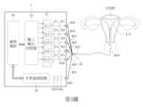
第1圖為本發明實施例之光學檢測系統之示意圖。Figure 1 is a schematic diagram of an optical detection system according to an embodiment of the present invention.

第2圖為本發明實施例之光學檢測系統之變化實施例示意圖。Figure 2 is a schematic diagram of a modified embodiment of the optical detection system according to the embodiment of the present invention.

第3圖為本發明實施例之應用於子宮內膜檢測之示意圖。Figure 3 is a schematic diagram of an embodiment of the present invention applied to endometrial detection.

第4圖至第8圖為本發明實施例之光學檢測系統之光譜信號之變化實施例示意圖。Figures 4 to 8 are schematic diagrams of changes in spectral signals of the optical detection system according to embodiments of the present invention.

在說明書及後續的申請專利範圍當中使用了某些詞彙來指稱特定的元件。所屬領域中具有通常知識者應可理解,硬體製造商可能會用不同的名詞來稱呼同一個元件。本說明書及後續的申請專利範圍並不以名稱的差異來做為區分元件的方式,而是以元件在功能上的差異來做為區分的準則。在通篇說明書及後續的申請專利範圍當中所提及的「包含」係為一開放式的用語,故應解釋成「包含但不限定於」。以外,「耦接」一詞在此係包含任何直接及間接的電氣連接手段。因此,若文中描述一第一裝置耦接於一第二裝置,則代表該第一裝置可直接電氣連接於該第二裝置,或透過其他裝置或連接手段間接地電氣連接至該第二裝置。Certain words are used in the description and subsequent patent claims to refer to specific components. It will be understood by those with ordinary knowledge in the art that hardware manufacturers may use different terms to refer to the same component. The scope of this specification and subsequent patent applications does not depend on the difference in name.The way to distinguish components is to use the functional differences of components as the criterion for differentiation. The "include" mentioned throughout the specification and subsequent patent claims is an open-ended term, and therefore should be interpreted as "include but not limited to". In addition, the word "coupling" here includes any direct and indirect means of electrical connection. Therefore, if a first device is coupled to a second device, it means that the first device can be directly electrically connected to the second device, or indirectly electrically connected to the second device through other devices or connections.

請參考第1圖,第1圖為本發明實施例之一光學檢測系統1之示意圖。光學檢測系統1包含有一光源裝置10、一光學感測裝置20、一處理電路30以及一光纖模組40。光源裝置10用以產生光線。光學感測裝置20用來偵測光譜信號。光纖模組40耦接於光源裝置10及光學感測裝置20。光纖模組40用來導引及傳送光源裝置10所產生之光線以照射至使用者人體的受測區域。並且光纖模組40用以收集與接收來自人體受測區域的反應光束並將反應光束傳送提供至光學感測裝置20。例如,光源裝置10產生一光線並利用光纖模組40來導引及傳送光源裝置10所產生之光線以照射至使用者人體之一目標組織區域,以及透過光纖模組40接收來自目標組織區域的反應光束並傳送至光學感測裝置20。光學感測裝置20偵測來自目標組織區域的反應光束以取得目標組織區域之一目標光譜信號。例如,光源裝置10產生一光線並利用光纖模組40來導引及傳送所產生之光線以照射至使用者人體之一參考組織區域,以及透過光纖模組40接收來自參考組織區域的反應光束並傳送至光學感測裝置20。光學感測裝置20偵測來自參考組織區域的反應光束以取得參考組織區域之一參考光譜信號。處理電路30用來根據目標光譜信號及參考光譜信號,計算出目標組織區域之一健康狀況參數。光源裝置10可包括紅外光發光二極體、雷射二極體或是其他任何可發射光線之裝置。處理電路30可控制光源裝置10產生所需光源。光學感測裝置20可為一光譜儀或一光譜分析儀,但不以此為限。Please refer to Figure 1 , which is a schematic diagram of an optical detection system 1 according to an embodiment of the present invention. The optical detection system 1 includes alight source device 10 , anoptical sensing device 20 , aprocessing circuit 30 and anoptical fiber module 40 . Thelight source device 10 is used to generate light. Theoptical sensing device 20 is used to detect spectral signals. Theoptical fiber module 40 is coupled to thelight source device 10 and theoptical sensing device 20 . Theoptical fiber module 40 is used to guide and transmit the light generated by thelight source device 10 to illuminate the measured area of the user's body. And theoptical fiber module 40 is used to collect and receive the reaction light beam from the human body being measured area and transmit the reaction light beam to theoptical sensing device 20 . For example, thelight source device 10 generates a light and uses theoptical fiber module 40 to guide and transmit the light generated by thelight source device 10 to illuminate a target tissue area of the user's body, and receives light from the target tissue area through theoptical fiber module 40 The reaction beam is transmitted to theoptical sensing device 20 . Theoptical sensing device 20 detects the reaction light beam from the target tissue area to obtain a target spectrum signal of the target tissue area. For example, thelight source device 10 generates a light and uses theoptical fiber module 40 to guide and transmit the generated light to illuminate a reference tissue area of the user's body, and receives the reaction light beam from the reference tissue area through theoptical fiber module 40 and transmitted to theoptical sensing device 20. Theoptical sensing device 20 detects the reaction light beam from the reference tissue area to obtain a reference spectrum signal of the reference tissue area. Theprocessing circuit 30 is used to calculate a health status parameter of the target tissue region based on the target spectrum signal and the reference spectrum signal. Thelight source device 10 may include an infrared light emitting diode, a laser diode or any other device that can emit light. Theprocessing circuit 30 can control thelight source device 10 to generate the required light source. Theoptical sensing device 20 may be a spectruminstrument or a spectrum analyzer, but is not limited to this.

處理電路30可根據目標光譜信號及參考光譜信號當中之至少一者計算出對應於目標組織區域之一健康狀況參數。健康狀況參數可包含一組織含氧率、一組織發炎率、一組織增生率、一組織均勻率當中之至少一者,但不以此為限。處理電路30可根據前述對應於目標組織區域之健康狀況參數當中之至少一者來判斷出目標組織區域之健康狀況。處理電路30可為一中央處理器(central processing unit,CPU)、一微處理器(microprocessor)、一數位信號處理器(digital signal processor,DSP)、可編程控制器(programmable controller)、一圖形處理器(Graphic Processing Unit,GPU)、一可編程邏輯裝置(programmable logic device,PLD)、或其他類似的裝置,或是該些裝置的組合,但不以此為限。Theprocessing circuit 30 may calculate a health status parameter corresponding to the target tissue region based on at least one of the target spectrum signal and the reference spectrum signal. The health status parameter may include at least one of a tissue oxygen content rate, a tissue inflammation rate, a tissue proliferation rate, and a tissue uniformity rate, but is not limited to this. Theprocessing circuit 30 may determine the health status of the target tissue region based on at least one of the aforementioned health status parameters corresponding to the target tissue region. Theprocessing circuit 30 may be a central processing unit (CPU), a microprocessor, a digital signal processor (DSP), a programmable controller, or a graphics processing unit. A Graphic Processing Unit (GPU), a programmable logic device (PLD), or other similar devices, or a combination of these devices, but is not limited to this.

請參考第2圖,第2圖為本發明實施例之光學檢測系統1之一變化實施例示意圖。如第2圖所示,光學檢測系統1另包含有一輸入輸出控制器(input/output controller,I/O controller)50、濾鏡F0~F5以及透鏡N0~N5、濾鏡F0~F5、透鏡N0~N5及狹縫片S0。第2圖所示,光源裝置10包括光源L1~L5。光源L1~L5可為單頻光源或寬頻光源。例如,光源L1及L2為寬頻光源,光源L3~L5為單頻光源,但不以此為限。光源L1~L5個別所發出之光線,將個別先經過濾鏡F1~F5再經過透鏡N1~N5再進入光纖模組40。例如,當光源L1~L5之其中一者發射出光線,所發射出的光線經由相應的濾鏡及透鏡進入光纖模組40,再經由光纖模組40將光源所發射的光線導引至受測區域。由光纖模組40傳回的光線,將經過透鏡N0,其次經過濾鏡F0,再經過狹縫片S0後進入光學感測裝置20。Please refer to Figure 2. Figure 2 is a schematic diagram of a variation of the optical detection system 1 according to the embodiment of the present invention. As shown in Figure 2, the optical detection system 1 also includes an input/output controller (I/O controller) 50, filters F0~F5, lenses N0~N5, filters F0~F5, and lens N0 ~N5 and slit piece S0. As shown in FIG. 2 , thelight source device 10 includes light sources L1 to L5. The light sources L1~L5 can be single-frequency light sources or broadband light sources. For example, the light sources L1 and L2 are broadband light sources, and the light sources L3 to L5 are single-frequency light sources, but they are not limited to this. The light emitted by the light sources L1 ~ L5 will first pass through the filters F1 ~ F5 and then pass through the lenses N1 ~ N5 before entering theoptical fiber module 40 . For example, when one of the light sources L1 to L5 emits light, the emitted light enters theoptical fiber module 40 through the corresponding filter and lens, and then theoptical fiber module 40 guides the light emitted by the light source to the test object. area. The light returned by theoptical fiber module 40 will pass through the lens N0, then pass through the filter F0, and then pass through the slit S0 before entering theoptical sensing device 20.

光源裝置10之光源的種類、頻率與數量可依不同之需要而設置。每一光源可包括發光二極體(light emitting diode,LED)、雷射二極體或是其他任何可發射光線之裝置。例如,光源可包括波長為280nm、365nm、405nm、522nm、465nm、532nm、600nm、637nm、750nm、785nm、800nm或1064nm之單頻光源,但不以此為限。例如光源可為低能量雷射二極體,例如小於80毫瓦(mW)之雷射二極體。例如,光源可包括波長範圍為200nm~500nm、400~600nm、500~650nm、400~900nm或600~1050nm之寬頻光源。例如光源可為LED發光二極體或氙燈、氘燈、溴鎢燈,但不以此為限。例如,濾鏡F0可為陷波濾鏡(notch filter)、邊緣濾鏡(edge filter),但不以此為限。例如濾鏡F1~F5可為雷射線濾鏡(laser line filter),但不以此為限。The type, frequency and quantity of the light sources of thelight source device 10 can be set according to different needs. EveryA light source may include a light emitting diode (LED), a laser diode, or any other device that can emit light. For example, the light source may include a single-frequency light source with a wavelength of 280nm, 365nm, 405nm, 522nm, 465nm, 532nm, 600nm, 637nm, 750nm, 785nm, 800nm or 1064nm, but is not limited thereto. For example, the light source may be a low energy laser diode, such as a laser diode less than 80 milliwatts (mW). For example, the light source may include a broadband light source with a wavelength range of 200nm~500nm, 400~600nm, 500~650nm, 400~900nm or 600~1050nm. For example, the light source can be an LED light-emitting diode, a xenon lamp, a deuterium lamp, or a bromine-tungsten lamp, but is not limited to this. For example, the filter F0 can be a notch filter or an edge filter, but is not limited thereto. For example, the filters F1 to F5 can be laser line filters, but are not limited to this.

在一實施例中,處理電路30可控制光源裝置10產生所需光線。例如,如第2圖所示,輸入輸出控制器50耦接於處理電路30以及光源裝置10之間,處理電路30可經由輸入輸出控制器50來控制光源裝置10產生光線。光學檢測系統1可透過光纖模組40將光源裝置10所發射的光線導引並照射至受測區域,並且透過光纖模組40將受測區域的反應光束傳送至光學感測裝置20以使光學感測裝置20偵測受測區域的反應光束以獲得相應光譜信號。光纖模組40包含有光纖束組件402、光纖束組件護套404以及光纖連接器406。光纖束組件402包含複數條光纖400。光纖400經由光纖連接器406耦接至光源裝置10以及光學感測裝置20。光纖束組件護套404用以包覆或覆蓋住光纖束組件402以保護光纖束組件402。光纖束組件護套404可經由滅菌處理後而被設置包覆於光纖束組件402外圍。光纖束組件402可為僅能一次使用之拋棄式光纖束組件。光纖束組件護套404可為僅能一次使用之拋棄式光纖束組件護套。光纖組件護套404的材料可為軟質材質。光纖組件護套404的材料可為透明材料。光纖組件護套404的材料可包括鐵氟龍(Teflon)、矽、聚乙烯、聚氨酯或聚氯乙烯,但不以此為限。請繼續參考第2圖,光纖模組40至少包含有一條光纖用以將光源裝置10所發射的光線導引並照射至受測區域(即目標組織區域或參考組織區域),例如,如第2圖所示,透鏡N1~N5分別連接至一相應光纖連接器406及光纖400,以將相應光源所發射出之光線透過相應光纖400導引至受測區域。並且光纖模組40至少包含有一條光纖用以將受測區域的反應光束傳送至光學感測裝置20,使得光學感測裝置20偵測出相應光譜信號。例如,如第2圖所示,透鏡N0連接至一相應光纖連接器406及光纖400。當光纖模組40接收到受測區域的反應光束,受測區域的反應光束經由相應光纖連接器406、光纖400、透鏡N0、濾鏡F0及狹縫片S0而被傳送提供至光學感測裝置20。In one embodiment, theprocessing circuit 30 can control thelight source device 10 to generate required light. For example, as shown in FIG. 2 , the input/output controller 50 is coupled between theprocessing circuit 30 and thelight source device 10 . Theprocessing circuit 30 can control thelight source device 10 to generate light through the input/output controller 50 . The optical detection system 1 can guide and illuminate the light emitted by thelight source device 10 to the measured area through theoptical fiber module 40, and transmit the reaction beam of the measured area to theoptical sensing device 20 through theoptical fiber module 40 to make the optical Thesensing device 20 detects the reaction light beam in the measured area to obtain corresponding spectral signals. Thefiber optic module 40 includes a fiberoptic bundle assembly 402, a fiber opticbundle assembly jacket 404, and afiber optic connector 406. Opticalfiber bundle assembly 402 includes a plurality ofoptical fibers 400. Theoptical fiber 400 is coupled to thelight source device 10 and theoptical sensing device 20 via theoptical fiber connector 406 . The optical fiberbundle assembly jacket 404 is used to wrap or cover the opticalfiber bundle assembly 402 to protect the opticalfiber bundle assembly 402. The optical fiberbundle assembly sheath 404 can be disposed to cover the periphery of the opticalfiber bundle assembly 402 after sterilization. Fiberoptic bundle assembly 402 may be a disposable fiber optic bundle assembly that can be used only once. Fiber opticbundle assembly jacket 404 may be a disposable fiber optic bundle assembly jacket that is intended for single use only. The material of the opticalfiber component sheath 404 can be a soft material. The material of the opticalfiber assembly jacket 404 may be a transparent material. The material of the opticalfiber assembly sheath 404 may include, but is not limited to, Teflon, silicon, polyethylene, polyurethane or polyvinyl chloride. Please continue to refer to Figure 2,Theoptical fiber module 40 includes at least one optical fiber for guiding and irradiating the light emitted by thelight source device 10 to the measured area (ie, the target tissue area or the reference tissue area). For example, as shown in Figure 2, the lens N1~ N5 is connected to a correspondingoptical fiber connector 406 andoptical fiber 400 respectively to guide the light emitted by the corresponding light source to the measured area through the correspondingoptical fiber 400. And theoptical fiber module 40 includes at least one optical fiber for transmitting the reaction light beam of the measured area to theoptical sensing device 20, so that theoptical sensing device 20 detects the corresponding spectral signal. For example, as shown in Figure 2, lens N0 is connected to a correspondingfiber optic connector 406 andoptical fiber 400. When theoptical fiber module 40 receives the reaction light beam of the measured area, the reaction light beam of the measured area is transmitted to the optical sensing device through the correspondingoptical fiber connector 406,optical fiber 400, lens N0, filter F0 and slit piece S0. 20.

本發明實施例所述目標組織區域與參考組織區域可為生物體的活體組織區域。例如,本發明實施例所述目標組織區域與參考組織區域可為同一人體之活體組織區域。本發明實施例所述之參考組織區域可為與目標組織區域所屬同一人體的健康組織。也就是說,本發明實施例所述目標組織區域與參考組織區域可為同一人體之組織區域且參考組織區域為同一人體之健康組織區域。本發明實施例之目標組織區域以及參考組織區域可以是人體或動物之黏膜組織或其他生物體組織。例如,目標組織區域可為人體之黏膜組織,但不以此為限。例如,參考組織區域可為位於人體之大拇指指腹、大腿內側的健康組織,但不以此為限。黏膜組織包括眼結膜之黏膜、口腔黏膜、鼻咽黏膜、呼吸道黏膜、肺部黏膜、食道黏膜、胃壁黏膜、腸道黏膜、尿道黏膜、生殖道黏膜、泌尿道、生殖道黏膜及子宮黏膜(或稱子宮內膜),但不以此為限。例如,當欲檢測之目標組織區域或參考組織區域為一人體60之黏膜組織600時,可將光纖模組40經由人體60之一體表開口606進入體內管道604,並且進入到達人體60之體內腔室602內。由於光纖束組件護套404已經過滅菌處理,因而能使檢測者免於受到感染。如第2圖所示,於光源裝置10產生光線時可透過光纖模組40將光源裝置10所發射的光線導引並照射至黏膜組織600。黏膜組織600內的特定生化分子經過光源裝置10所發射的光線激發後產生反射、拉曼散射、螢光或磷光反應產生的反應光束,所述反應光束包括反射光及/或散色光。黏膜組織內包含有許多自發螢光特性之生物標記(biomarkers)分子,例如NADP、NADPH、NADH、FAD、[CP(OME)3]、[CP(ME)3]、膠原(collagen)、血紅素(hemoglobin)、紫質(porphyrin)及紫質衍生物。所述反應光束經由光纖模組40之光纖400導引回傳至光學感測裝置20以使光學感測裝置20分析所述反應光束以產生相應光譜信號。光學感測裝置20所偵測出之光譜信號反映出黏膜組織或黏膜組織液內的生物分子的種類及濃度。處理電路30可依據光學感測裝置20所偵測出之光譜信號判斷出黏膜組織的含氧率、細胞增長、黏膜發炎情況、黏膜組織的厚度及均勻程度,如此一來,本發明實施例將可提供即時光譜信號之健康狀況參數做為健康狀況的判斷依據而實現即時性的精準檢測。相較於傳統內視鏡方式,本發明實施例之光學檢測系統1可大幅減少檢測者在檢驗過程中之不舒適感。再者,傳統雷射光學式診斷方式是以黏膜表面之影像資訊來進行診斷。相較之下,本發明實施例之檢測結果並非為無法量化的影像,而是可具體量化的數值,因而可降低人為因肉眼判定造成失誤之機率。本發明實施例可即時提供透過光譜信號所計算判斷出之健康狀況參數而可精確做為早期黏膜病徵之參考數值,進而大幅提昇診斷正確率。The target tissue region and the reference tissue region described in the embodiment of the present invention may be living tissue regions of an organism. For example, the target tissue region and the reference tissue region described in this embodiment of the present invention may be living tissue regions of the same human body. The reference tissue region described in the embodiment of the present invention may be a healthy tissue belonging to the same human body as the target tissue region. That is to say, the target tissue area and the reference tissue area in the embodiment of the present invention may be tissue areas of the same human body, and the reference tissue area may be a healthy tissue area of the same human body. The target tissue area and the reference tissue area in the embodiment of the present invention may be human or animal mucosal tissue or other biological tissue. For example, the target tissue area can be human mucosal tissue, but is not limited thereto. For example, the reference tissue area may be healthy tissue located on the thumb pad or inner thigh of the human body, but is not limited to this. Mucosal tissues include conjunctival mucosa, oral mucosa, nasopharyngeal mucosa, respiratory mucosa, lung mucosa, esophageal mucosa, gastric wall mucosa, intestinal mucosa, urethral mucosa, reproductive tract mucosa, urinary tract, genital tract mucosa and uterine mucosa (or called endometrium), but not limited to this. For example, when the target tissue area or reference tissue area to be detected is themucosal tissue 600 of ahuman body 60 , theoptical fiber module 40 can be inserted into theinternal pipeline 604 through a body surface opening 606 of thehuman body 60 , and then enter the internal cavity of thehuman body 60 Inroom 602. Because the optical fiberbundle assembly sheath 404 has been sterilized, the examiner is protected from infection.As shown in FIG. 2 , when thelight source device 10 generates light, the light emitted by thelight source device 10 can be guided and irradiated to themucosal tissue 600 through theoptical fiber module 40 . Specific biochemical molecules in themucosal tissue 600 are excited by the light emitted by thelight source device 10 and generate reaction beams generated by reflection, Raman scattering, fluorescence or phosphorescence reactions. The reaction beams include reflected light and/or dispersed light. Mucosal tissue contains many biomarker molecules with autofluorescent properties, such as NADP, NADPH, NADH, FAD, [CP(OME)3], [CP(ME)3], collagen, and heme (hemoglobin), porphyrin and porphyrin derivatives. The reaction beam is guided back to theoptical sensing device 20 through theoptical fiber 400 of thefiber optic module 40 so that theoptical sensing device 20 analyzes the reaction beam to generate a corresponding spectrum signal. The spectral signals detected by theoptical sensing device 20 reflect the types and concentrations of biomolecules in the mucosal tissue or mucosal tissue fluid. Theprocessing circuit 30 can determine the oxygen content of the mucosal tissue, cell growth, mucosal inflammation, and the thickness and uniformity of the mucosal tissue based on the spectral signal detected by theoptical sensing device 20. In this way, the embodiment of the present invention will It can provide health status parameters of real-time spectral signals as a basis for judging health status to achieve real-time and accurate detection. Compared with the traditional endoscope method, the optical inspection system 1 of the embodiment of the present invention can significantly reduce the discomfort of the inspector during the inspection process. Furthermore, traditional laser optical diagnosis methods use imaging information on the mucosal surface for diagnosis. In comparison, the detection results of the embodiments of the present invention are not images that cannot be quantified, but values that can be specifically quantified, thereby reducing the probability of human errors caused by visual judgment. Embodiments of the present invention can provide real-time health status parameters calculated and judged through spectral signals, which can be accurately used as reference values for early mucosal disease symptoms, thus greatly improving the accuracy of diagnosis.

請參考第3圖,第3圖為本發明實施例之光學檢測系統1應用於子宮內膜檢測之示意圖。例如光學檢測系統1可應用於一子宮內膜監測儀。當所欲檢測之目標組織區域為人體之子宮內膜的黏膜組織時,例如,目標組織區域可為位於子宮頂端、子宮腔、子宮頸內口、子宮頸或子宮頸外口的子宮內膜,但不以此為限。如第3圖所示,可讓光纖模組40進入子宮UT之腔室內以使光源裝置10所產生光線透過光纖模組40導引並照射至子宮內膜ENDO。子宮內膜ENDO內的特定生化分子經過光源裝置10所發射的光線激發後產生反射、拉曼散射、螢光或磷光反應產生的反應光束,反應光束經由光纖模組40之光纖400導引回傳至光學感測裝置20以使光學感測裝置20偵測出相應光譜信號。Please refer to Figure 3. Figure 3 is a schematic diagram of the optical detection system 1 used in endometrial detection according to the embodiment of the present invention. For example, the optical detection system 1 can be applied to an endometrial monitor. When the target tissue area to be detected is the mucosal tissue of the endometrium of the human body, for example, the target tissue area can be the endometrium located at the apex of the uterus, the uterine cavity, the internal os of the cervix, the cervix or the external os of the cervix, But it is not limited to this. As shown in Figure 3, theoptical fiber module 40 can be allowed to enter the cavity of the uterus UT to make thelight source device 10The generated light is guided through theoptical fiber module 40 and irradiated to the endometrium ENDO. Specific biochemical molecules in the endometrium ENDO are excited by the light emitted by thelight source device 10 and then produce a reaction beam generated by reflection, Raman scattering, fluorescence or phosphorescence reaction. The reaction beam is guided and transmitted back through theoptical fiber 400 of theoptical fiber module 40 to theoptical sensing device 20 so that theoptical sensing device 20 detects the corresponding spectrum signal.

關於光學檢測系統1之詳細操作方式,請繼續參考以下說明。於一實施例中,健康狀況參數包含一組織含氧率。光源裝置10經配置以產生具一波長範圍WR之寬頻光線。例如,光源裝置1所發射之寬頻光線的波長範圍WR可介於300奈米(nm)~380nm、400nm~600nm、500nm~650nm、600nm~850nm、650nm~950nm或400nm~900nm,但不以此為限。例如,若目前所欲檢測的目標組織區域是人體的黏膜組織,例如子宮內膜。參考組織區域為人體之一健康組織區域,例如健康之大拇指指腹。在此情況下,光源裝置10經配置以產生具一波長範圍WR之寬頻光線以照射至參考組織區域(例如大拇指指腹)。光學感測裝置20偵測來自參考組織區域(大拇指指腹)之一參考光譜信號SR。例如光學感測裝置20可偵測收集由參考組織區域所反射、散射、螢光或磷光反應產生的反應光束以產生參考光譜信號SR。接著,光源裝置10經配置以產生具波長範圍WR之寬頻光線以照射至目標組織區域(子宮內膜)。並且,光學感測裝置20偵測來自目標組織區域之一目標光譜信號ST。例如光學感測裝置20可偵測收集由目標組織區域所反射、散射螢光或磷光反應產生的反應光束以產生目標光譜信號STFor the detailed operation of the optical detection system 1, please continue to refer to the following instructions. In one embodiment, the health parameter includes a tissue oxygen content rate. Thelight source device 10 is configured to generate broadband light having a wavelength rangeWR . For example, the wavelength rangeWR of the broadband light emitted by the light source device 1 can be between 300 nanometers (nm) ~ 380nm, 400nm ~ 600nm, 500nm ~ 650nm, 600nm ~ 850nm, 650nm ~ 950nm or 400nm ~ 900nm, but not This is the limit. For example, if the target tissue area currently to be detected is human mucosal tissue, such as endometrium. The reference tissue area is a healthy tissue area of the human body, such as the healthy thumb pad. In this case, thelight source device 10 is configured to generate broadband light with a wavelength rangeWR to illuminate the reference tissue area (eg, thumb pad). Theoptical sensing device 20 detects a reference spectrum signalSR from a reference tissue area (thumb pad). For example, theoptical sensing device 20 can detect and collect the reaction light beam generated by the reflection, scattering, fluorescence or phosphorescence reaction of the reference tissue area to generate the reference spectrum signalSR . Next, thelight source device 10 is configured to generate broadband light with a wavelength rangeWR to illuminate the target tissue area (endometrium). Furthermore, theoptical sensing device 20 detects a target spectrum signalST from the target tissue area. For example, theoptical sensing device 20 can detect and collect reaction light beams generated by fluorescence or phosphorescence reactions reflected and scattered by the target tissue area to generate the target spectrum signalST .

進一步地,處理電路30可根據目標光譜信號ST及參考光譜信號SR計算出對應於目標組織區域之組織含氧率。處理電路30可判斷出光學感測裝置20所感測到之參考光譜信號SR於一第一特徵波長之一參考光強度值。例如所述第一特徵波長為520nm、530nm、540nm、568nm、578nm、588nm、595nm、608nm、650nm、660nm、670nm或800nm,但不以此為限。例如所述第一特徵波長係有關於氧化血紅素(oxygenated hemoglobin)的特徵波長。例如所述第一特徵波長係於568nm~588nm之間或650nm~670nm之間。例如所述第一特徵波長係於波長範圍WR之範圍內。處理電路30可分析判斷出參考光譜信號SR於一第一波長範圍內之至少一個參考峰值光強度值。每一參考峰值光強度值係對應於第一波長範圍內之一相應波長。每一參考峰值光強度值可大於參考光譜信號SR於第一特徵波長之參考光強度值。處理電路30根據參考光譜信號SR於第一波長範圍內之至少一個參考峰值光強度值以及參考光譜信號SR於一第一特徵波長之一參考光強度值計算出參考光譜信號SR於第一特徵波長之一參考光吸收強度。例如,處理電路30可計算出所述至少一個參考峰值光強度值之一平均值,並將所述至少一個參考峰值光強度值之平均值減去參考光譜信號SR於第一特徵波長之參考光強度值以得到參考光譜信號SR於第一特徵波長之參考光吸收強度。Further, theprocessing circuit 30 can calculate the tissue oxygen content rate corresponding to the target tissue region based on the target spectrum signalST and the reference spectrum signalSR . Theprocessing circuit 30 can determine a reference light intensity value of the reference spectrum signalSR sensed by theoptical sensing device 20 at a first characteristic wavelength. For example, the first characteristic wavelength is 520nm, 530nm, 540nm, 568nm, 578nm, 588nm, 595nm, 608nm, 650nm, 660nm, 670nm or 800nm, but is not limited to this. For example, the first characteristic wavelength is related to the characteristic wavelength of oxygenated hemoglobin. For example, the first characteristic wavelength is between 568nm~588nm or between 650nm~670nm. For example, the first characteristic wavelength is within the wavelength rangeWR . Theprocessing circuit 30 can analyze and determine at least one reference peak light intensity value of the reference spectrum signal SR within a first wavelength range. Each reference peak light intensity value corresponds to a corresponding wavelength within the first wavelength range. Each reference peak light intensity value may be greater than the reference light intensity value of the reference spectrum signalSR at the first characteristic wavelength. Theprocessing circuit 30 calculates the reference spectrum signal SR based on at least one reference peak light intensity value of the reference spectrum signal SR in the first wavelength range and a reference light intensity value of the reference spectrum signal SR at a first characteristic wavelength. A reference to the intensity of light absorption at one of the characteristic wavelengths. For example, theprocessing circuit 30 may calculate an average value of the at least one reference peak light intensity value, and subtract the reference spectral signal SR at the first characteristic wavelength from the average value of the at least one reference peak light intensity value. The light intensity value is used to obtain the reference light absorption intensity of the reference spectral signal SR at the first characteristic wavelength.

處理電路30可判斷出光學感測裝置20所感測到之目標光譜信號ST於所述第一特徵波長之一目標光強度值。處理電路30分析判斷出目標光譜信號ST於所述第一波長範圍內之至少一個峰值光強度值。每一峰值光強度值係對應於所述第一波長範圍內之相應波長。每一峰值光強度值可大於目標光譜信號ST於所述第一特徵波長之目標光強度值。處理電路30根據至少一個峰值光強度值以及目標光譜信號ST於所述第一特徵波長之目標光強度值計算出目標光譜信號ST於所述第一特徵波長之一目標光吸收強度。例如,處理電路30計算出所述至少一個峰值光強度值之平均值,並將所述至少一個峰值光強度值之平均值減去目標光譜信號ST於第一特徵波長之目標光強度值以得到目標光譜信號ST於第一特徵波長之目標光吸收強度。接著,處理電路30將目標光譜信號ST於所述第一特徵波長之目標光吸收強度除以參考光譜信號SR於所述第一特徵波長之參考光吸收強度以取得所述目標組織區域之組織含氧率。如此一來,處理電路30可根據所述目標組織區域之組織含氧率來判斷出目標組織區域之一健康狀況。Theprocessing circuit 30 can determine the target light intensity value of the target spectrum signalST sensed by theoptical sensing device 20 at the first characteristic wavelength. Theprocessing circuit 30 analyzes and determines at least one peak light intensity value of the target spectrum signal ST within the first wavelength range. Each peak light intensity value corresponds to a corresponding wavelength within the first wavelength range. Each peak light intensity value may be greater than the target light intensity value of the target spectrum signalST at the first characteristic wavelength. Theprocessing circuit 30 calculates a target light absorption intensity of the target spectrum signalST at the first characteristic wavelength based on at least one peak light intensity value and the target light intensity value of the target spectrum signalST at the first characteristic wavelength. For example, theprocessing circuit 30 calculates the average value of the at least one peak light intensity value, and subtracts the target light intensity value of the target spectrum signal ST at the first characteristic wavelength from the average value of the at least one peak light intensity value. The target light absorption intensity of the target spectrum signal ST at the first characteristic wavelength is obtained. Next, theprocessing circuit 30 divides the target light absorption intensity of the target spectrum signal ST at the first characteristic wavelength by the reference light absorption intensity of the reference spectrum signal SR at the first characteristic wavelength to obtain the target tissue area. Tissue oxygen content. In this way, theprocessing circuit 30 can determine the health status of the target tissue region based on the tissue oxygen content rate of the target tissue region.

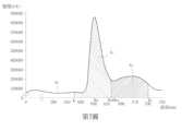
例如,請參考第4圖,第4圖為本發明第一實施例之光學感測裝置20所偵測到之光譜信號之實施例示意圖。假設一預設波長範圍WR1為500nm~650nm,特徵波長λT1為578nm。特徵波長λT1係有關於氧化血紅素的特徵波長。光源裝置10產生具波長範圍為400nm~900nm之寬頻光線照射至目標組織區域(例如子宮內膜),光學感測裝置20偵測到來自目標組織區域之一目標光譜信號ST。光源裝置10產生具波長範圍為400nm~900nm之寬頻光線照射至參考組織區域(例如大拇指指腹),光學感測裝置20偵測到來自參考組織區域之一參考光譜信號SR。處理電路30可將參考光譜信號SR於波長範圍WR1當中選取出所有強度值出現轉折之處的光強度值以做為參考峰值光強度值。也就是說,在參考光譜信號SR之波長範圍WR1之中若有光強度值從遞增轉變為遞減的轉折點所對應之光強度值可被選擇做為參考峰值光強度值。如第4圖所示,在波長範圍WR1(500nm~650nm)當中,參考光譜信號SR於波長λ1(例如520nm)及波長λ2(例如608nm)之處強度值出現轉折。處理電路30將參考光譜信號SR中對應於波長λ1之參考光強度值Iλ1,R及對應於波長λ2之參考光強度值Iλ2,R判斷做為參考峰值光強度值。參考光強度值Iλ1,R、Iλ2,R大於參考光譜信號SR於特徵波長λT1之參考光強度值IλT1,R。如此一來,處理電路30可根據參考光譜信號SR於波長範圍WR1內之至少一個參考峰值光強度值(即參考光強度值Iλ1,R、Iλ2,R)及參考光譜信號SR於特徵波長λT1之參考光強度值IλT1,R計算出參考光譜信號SR於特徵波長λT1之一參考光吸收強度JλT1,R。其中處理電路30可依據式(1)計算出參考光譜信號SR於特徵波長λT1之光吸收強度JλT1,R:JλT1,R=(Iλ1,R+Iλ2,R)/2-IλT1,R (1)For example, please refer to Figure 4. Figure 4 is a schematic diagram of a spectral signal detected by theoptical sensing device 20 according to the first embodiment of the present invention. Assume that a preset wavelength range WR1 is 500nm~650nm, and the characteristic wavelengthλT1 is 578nm. The characteristic wavelengthλT1 is related to the characteristic wavelength of oxidized heme. Thelight source device 10 generates broadband light with a wavelength range of 400 nm to 900 nm and irradiates the target tissue area (eg, endometrium), and theoptical sensing device 20 detects a target spectrum signalST from the target tissue area. Thelight source device 10 generates broadband light with a wavelength range of 400 nm to 900 nm and irradiates it to a reference tissue area (such as the thumb pad), and theoptical sensing device 20 detects a reference spectrum signalSR from the reference tissue area. Theprocessing circuit 30 can select the light intensity values at which all intensity values turn in the wavelength rangeWR1 from the reference spectrum signal SR as the reference peak light intensity value. That is to say, if there is a light intensity value corresponding to a turning point in which the light intensity value changes from increasing to decreasing in the wavelength rangeWR1 of the reference spectrum signal SR , the light intensity value can be selected as the reference peak light intensity value. As shown in Figure 4, in the wavelength range WR1 (500nm~650nm), the intensity value of the reference spectrum signal SR turns at wavelengthλ1 (for example, 520 nm) and wavelengthλ2 (for example, 608 nm). Theprocessing circuit 30 determines the reference light intensity value I λ1,R corresponding to the wavelengthλ 1 and the reference light intensity value Iλ 2,R corresponding to the wavelengthλ2 in the reference spectrum signal SR as the reference peak light intensity value. The reference light intensity values Iλ 1,R and Iλ 2,R are greater than the reference light intensity value I λ T1,R of the reference spectrum signal SR at the characteristic wavelengthλT1 . In this way, theprocessing circuit 30 can determine at least one reference peak light intensity value (ie, reference light intensity value Iλ 1,R , Iλ 2,R ) within the wavelength rangeWR1 ofthe reference spectrum signal S R and the reference spectrum signal. The reference light intensity value I λT1, Rof S R at the characteristic wavelengthλ T1 is used to calculate the reference light absorption intensity J λT1 ,R of the reference spectral signal S R at the characteristic wavelengthλT1 . Theprocessing circuit 30 can calculate the light absorption intensity Jλ T1,R of the reference spectrum signal S R at the characteristic wavelengthλT1 according to the formula (1): JλT1,R =(Iλ1,R +Iλ2,R )/2 -IλT1,R (1)

處理電路30可將目標光譜信號ST於波長範圍WR1當中選取出所有強度值出現轉折且強度值大於目標光譜信號ST於特徵波長λT1之光強度值IλT1,M之光強度值以做為峰值光強度值。如第4圖所示,在波長範圍WR1(500nm~650nm)當中,目標光譜信號ST在波長λ1(例如520nm)及波長λ2(例如608nm)之處的強度值出現轉折。處理電路30將目標光譜信號ST當中對應於波長λ1之光強度值Iλ1,M及對應於波長λ2之光強度值Iλ2,M判斷做為目標光譜信號ST之峰值光強度值。光強度值Iλ1,M、Iλ2,M大於目標光譜信號ST於特徵波長λT1之光強度值IλT1,M。處理電路30可根據目標光譜信號ST於波長範圍WR1之峰值光強度值(即光強度值Iλ1,M、Iλ2,M)及目標光譜信號ST於特徵波長λT1之光強度值IλT1,M計算出目標光譜信號ST於特徵波長λT1之光吸收強度JλT1,M。其中處理電路30可依據式(2)計算出目標光譜信號ST於特徵波長λT1之光吸收強度JλT1,M並且依據式(3)計算出對應於目標組織區域之一組織含氧率O1:JλT1,M=(Iλ1,M+Iλ2,M)/2-IλT1,M (2)Theprocessing circuit 30 can select all the light intensity values of the target spectrum signal ST in the wavelength range WR1 that have a turning point and have an intensity value greater than the light intensity value Iλ T1,M of the target spectrum signal ST at the characteristic wavelengthλT1 as the peak light intensity value. As shown in Figure 4, in the wavelength range WR1 (500nm~650nm), the intensity value of the target spectrum signal ST turns at the wavelengthλ1 (for example, 520 nm) and the wavelengthλ2 (for example, 608 nm). Theprocessing circuit 30 determines the light intensity value Iλ 1,M corresponding to the wavelengthλ1 and thelight intensity value Iλ 2,M corresponding to the wavelengthλ2 in the target spectrum signal S T as the peak light of the target spectrum signal ST intensity value. The light intensity values Iλ 1,M and Iλ 2,M are greater than the light intensity value I λ T1,M of the target spectrum signal ST at the characteristic wavelengthλT1 . Theprocessing circuit 30 can perform the processing according to the peak light intensity value of the target spectrum signal ST in the wavelength rangeWR1 (ie, the light intensity values Iλ 1,M , Iλ 2,M ) and the light of the target spectrum signal ST at the characteristic wavelengthλT1 The intensity value Iλ T1,M is used to calculate the light absorption intensity J λT1, M of the target spectrum signal ST at the characteristic wavelengthλ T1. Theprocessing circuit 30 can calculate the light absorption intensity Jλ T1,M of the target spectrum signal ST at the characteristic wavelengthλT1 according to the formula (2), and calculate the tissue oxygen content rate corresponding to the target tissue region according to the formula (3). O1 : Jλ T1,M =(Iλ1,M +Iλ2,M )/2-IλT1,M (2)

O1=JλT1,M/JλT1,R (3)O1 =JλT1,M /JλT1,R (3)

當計算出對應於目標組織區域之一組織含氧率O1後,處理電路30可根據對應於目標組織區域之一組織含氧率O1來判斷出目標組織區域之健康狀況。此外,處理電路30亦可透過其他方式來計算出參考光譜信號SR於特徵波長λT1之光吸收強度以及目標光譜信號ST於特徵波長λT1之光吸收強度。接著,處理電路30再將目標光譜信號ST於特徵波長λT1之光吸收強度除以參考光譜信號SR於特徵波長λT1之光吸收強度以取得所述目標組織區域之組織含氧率。After calculating the tissue oxygen content rate O1 corresponding to the target tissue area, theprocessing circuit 30 can determine the health status of the target tissue area based on the tissue oxygen content rate O1 corresponding to the target tissue area. In addition, theprocessing circuit 30 can also calculate the light absorption intensity of the reference spectrum signal SR at the characteristic wavelengthλT1 and the light absorption intensity of the target spectrum signal ST at the characteristic wavelengthλT1 through other methods. Next, theprocessing circuit 30 divides the light absorption intensity of the target spectrum signal ST at the characteristic wavelengthλT1 by the light absorption intensity of the reference spectrum signalSR at the characteristic wavelengthλT1 to obtain the tissue oxygen content of the target tissue region.

請繼續參考第4圖,假設波長範圍WR2為650nm~850nm,特徵波長λT2為660nm。特徵波長λT2係有關於氧化血紅素的特徵波長。當光源裝置10產生具波長範圍為400nm~900nm之寬頻光線照射至目標組織區域(例如子宮內膜)以及參考組織區域(例如大拇指指腹),使得光學感測裝置20偵測到來自目標組織區域之一目標光譜信號ST以及來自參考組織區域之一參考光譜信號SR。如第4圖所示,在波長範圍WR2(650nm~850nm)當中,參考光譜信號SR於波長λ3(例如800nm)之處的強度值出現轉折。對應於波長λ3之參考光強度值Iλ3,R大於參考光譜信號SR於特徵波長λT2之參考光強度值IλT2,R。處理電路30可將參考光強度值Iλ3,R判斷做為參考峰值光強度值。由於僅有一個參考峰值光強度值(即參考光強度值Iλ3,R),不需再做平均值運算。處理電路30可將參考峰值光強度值(即參考光強度值Iλ3,R)與參考光譜信號SR於特徵波長λT2之參考光強度值IλT2,R相減以取得參考光譜信號SR於特徵波長λT2之一光吸收強度JλT2,R(即,JλT2,R=Iλ3,R-IλT2,R)。如第4圖所示,在波長範圍WR2(650nm~850nm)當中,目標光譜信號ST在波長λ3(例如800nm)之處的強度值出現轉折。對應於波長λ3之光強度值Iλ3,M大於目標光譜信號ST於特徵波長λT2之光強度值IλT2,M。處理電路30將光強度值Iλ3,M選做為目標光譜信號ST之峰值光強度值。處理電路30可將峰值光強度值(即光強度值Iλ3,M)與目標光譜信號ST於特徵波長λT2之光強度值IλT2,M相減以取得目標光譜信號ST於特徵波長λT2之一光吸收強度JλT2,M(即,JλT2,M=Iλ3,M-IλT2,M)。處理電路30將目標光譜信號ST於特徵波長λT2之一光吸收強度JλT2,M除以參考光譜信號SR於特徵波長λT2之一光吸收強度JλT2,R以計算出對應於目標組織區域之一組織含氧率O2(即,O2=JλT2,M//JλT2,RI)。當計算出對應於目標組織區域之一組織含氧率O2後,處理電路30可根據對應於目標組織區域之一組織含氧率O2來判斷出目標組織區域之健康狀況。Please continue to refer to Figure 4, assuming that the wavelength range WR2 is 650nm~850nm, and the characteristic wavelengthλT2 is 660nm. The characteristic wavelengthλT2 is related to the characteristic wavelength of oxidized heme. When thelight source device 10 generates broadband light with a wavelength range of 400nm~900nm and irradiates the target tissue area (such as the endometrium) and the reference tissue area (such as the thumb pad), theoptical sensing device 20 detects light from the target tissue. A target spectral signalST from one of the regions and a reference spectral signalSR from a reference tissue region. As shown in Figure 4, in the wavelength range WR2 (650nm~850nm), the intensity value of the reference spectrum signal SR at the wavelengthλ3 (for example, 800nm) turns. The reference light intensity value I λ3, R corresponding to the wavelengthλ 3 is greater than the reference light intensity value I λ T2,R of the reference spectrum signal SR at the characteristic wavelengthλT2 . Theprocessing circuit 30 may determine the reference light intensity value Iλ 3,R as the reference peak light intensity value. Since there is only one reference peak light intensity value (ie, the reference light intensity value Iλ 3,R ), there is no need to perform an average calculation. Theprocessing circuit 30 can subtract the reference peak light intensity value (i.e., the reference light intensity value Iλ 3,R ) from the reference light intensity value Iλ T2, R of the reference spectrum signal SR at the characteristic wavelengthλT2 to obtain the reference spectrum signal. SR has a light absorption intensity JλT2, R at one of the characteristic wavelengths λ T2 (ie, Jλ T2,R =Iλ 3,R -Iλ T2,R ). As shown in Figure 4, in the wavelength range WR2 (650nm~850nm), the intensity value of the target spectrum signal ST at the wavelengthλ3 (for example, 800nm) turns. The light intensity value I λ3, M corresponding to the wavelengthλ 3 is greater than the light intensity value I λT2 ,M of the target spectrum signal ST at the characteristic wavelengthλ T2 . Theprocessing circuit 30 selects the light intensity value Iλ 3,M as the peak light intensity value of the target spectrum signal ST . Theprocessing circuit 30 can subtract the peak light intensity value (ie, light intensity value Iλ 3,M ) from the light intensity value Iλ T2,M of the target spectrum signal ST at the characteristic wavelengthλT2 to obtain the target spectrum signal ST at The light absorption intensity JλT2, M at one of the characteristic wavelengths λ T2 (ie, Jλ T2,M =Iλ 3,M -Iλ T2,M ). Theprocessing circuit 30 divides the light absorption intensity J λ T2,M of the target spectrum signal ST at the characteristic wavelengthλT2 by the light absorption intensity JλT2 ,R of the reference spectrum signal SR at the characteristic wavelengthλ T2 to calculate the corresponding The tissue oxygen content O2 in one of the target tissue areas (ie, O2 =Jλ T2,M //Jλ T2,R I). After calculating a tissue oxygen content rate O2 corresponding to the target tissue area, theprocessing circuit 30 can determine the health status of the target tissue area based on a tissue oxygen content rate O2 corresponding to the target tissue area.

由於癌化或發炎細胞因處於持續複製之狀態,有高耗能之需求以利代謝活動,且亦會常有異常微血管增生之情形,因此相對於正常細胞有旺盛的異常代謝分子含量,血氧異常、黏膜構造不平滑、缺氧導致微生物菌相異常等情形將會發生,因此處理電路30可根據對應於目標組織區域之組織含氧率來判斷出目標組織區域之健康狀況。例如,子宮內膜的健康情況是影響女性不孕症的主因之一,子宮內膜只有在特定的著床窗期(Window of Implantation,WOI)期間接受胚胎著床始有成功的可能性並且著床窗期也會因人而異。目前關於子宮內膜的病理診斷方法通常係採取血液生化檢查、子宮內視鏡檢查、超音波掃描檢查、子宮內膜刮採檢體病理學檢查或子宮內膜容受性(Endometrial Receptivity Analysis,ERA)檢測等。血液生化檢查數值易受體質或是經期影響反應,只能做參考指標,也無法得知子宮結構是否有異狀。內視鏡及超音波只能檢查子宮內膜的結構,但無法得知其生理功能是否正常。子宮內膜刮採檢體屬於侵入性檢查,受檢測者需要局部麻醉而可能造成病患疼痛或出血,而且需將檢體送至病理科等待病理形態學檢查。由於不同經期天數不同時組織含氧率也會有所不同,例如經期天數第13天與第18天的組織含氧率會不同。組織含氧率亦會有上升、持平或下降之趨勢變化,因此透過本發明實施例可經由對應於目標組織區域之目標光譜信號及對應於參考組織區域之參考光譜信號計算出組織含氧率,進而觀察經期中組織含氧率的變化來判斷出著床窗期、組織缺氧程度以及缺氧的原因,藉以監測黏膜組織的健康程度。Because cancerous or inflammatory cells are in a state of continuous replication, they have high energy consumption requirements to facilitate metabolic activities, and often have abnormal capillary proliferation. Therefore, compared with normal cells, they have a stronger content of abnormal metabolic molecules and blood oxygen. Abnormalities, uneven mucosal structure, abnormal microbial phase caused by hypoxia, etc. will occur. Therefore, theprocessing circuit 30 can determine the health status of the target tissue area based on the tissue oxygen content rate corresponding to the target tissue area. For example, the health of the endometrium is one of the main causes of female infertility. Only during a specific window of implantation (WOI) does the endometrium have the possibility of successful embryo implantation and implantation. The bed window will also vary from person to person. The current pathological diagnosis methods for endometrium usually adopt blood biochemical examination, hysteroscopy, ultrasound scan, endometrial scraping specimen pathological examination or endometrial receptivity analysis (ERA). ) detection, etc. Blood biochemical test values are easily affected by body constitution or menstrual period. They can only be used as reference indicators, and it is impossible to know whether there are abnormalities in the uterine structure. Endoscopy and ultrasound can only examine the structure of the endometrium, but cannot determine whether its physiological function is normal. Endometrial scraping is an invasive examination that requires local anesthesia, which may cause pain or bleeding, and the specimen needs to be sent to the pathology department to await pathological morphological examination. Because the tissue oxygen content will be different in different menstrual days, for example, the tissue oxygen content will be different on the 13th day and the 18th day of the menstrual period. The tissue oxygen content rate will also tend to increase, remain flat, or decrease. Therefore, through embodiments of the present invention, the tissue oxygen content rate can be calculated through the target spectral signal corresponding to the target tissue area and the reference spectral signal corresponding to the reference tissue area. Then, changes in tissue oxygen content during menstruation are observed to determine the implantation window, degree of tissue hypoxia, and causes of hypoxia, thereby monitoring the health of mucosal tissue.

於一實施例中,健康狀況參數包含一組織增生率。光源裝置10經配置以產生一單頻光線。例如,光源裝置1所發射之單頻光線的波長可為522nm、532nm、600nm、637nm、673nm、750nm、785nm或800nm,但不以此為限。例如,若目前所欲檢測的目標組織區域是人體的黏膜組織,例如子宮內膜。參考組織區域為人體之一健康組織區域,例如健康之大拇指指腹或大腿內側。光源裝置10經配置以產生單頻光線以照射至參考組織區域,以及光學感測裝置20偵測來自參考組織區域之一參考光譜信號SR。光源裝置10經配置以產生前述單頻光線以照射至目標組織區域,且光學感測裝置20偵測來自目標組織區域之一目標光譜信號ST。如此一來,處理電路30可根據參考光譜信號SR及目標光譜信號ST計算出對應於目標組織區域之組織增生率。處理電路30計算出參考光譜信號SR於一第一波長範圍之一參考光強度面積。也就是說,處理電路30計算參考光譜信號SR於第一波長範圍內的各波長所對應光強度的累加結果以得到參考光強度面積。第一波長範圍可為300nm~380nm、400nm~600nm、500nm~650nm、600nm~850nm、640nm~800nm、400nm~900nm或600nm~1050nm,但不以此為限。處理電路30計算出目標光譜信號ST於所述第一波長範圍之一目標光強度面積。也就是說,處理電路30計算目標光譜信號ST於第一波長範圍內的各波長所對應光強度的累加結果以得到目標光強度面積。處理電路30將目標光譜信號ST於所述第一波長範圍之目標光強度面積除以參考光譜信號SR於所述第一波長範圍之參考光強度面積以取得所述目標組織區域之組織增生率。如此一來,處理電路30可根據所述目標組織區域之組織增生率來判斷出目標組織區域之健康狀況。In one embodiment, the health status parameter includes a tissue proliferation rate. Thelight source device 10 is configured to generate a single frequency light. For example, the wavelength of the single-frequency light emitted by the light source device 1 can be 522nm, 532nm, 600nm, 637nm, 673nm, 750nm, 785nm or 800nm, but is not limited thereto. For example, if the target tissue area currently to be detected is human mucosal tissue, such as endometrium. The reference tissue area is a healthy tissue area of the human body, such as a healthy thumb pad or inner thigh. Thelight source device 10 is configured to generate a single frequency light to illuminate the reference tissue area, and theoptical sensing device 20 detects a reference spectrum signalSR from the reference tissue area. Thelight source device 10 is configured to generate the aforementioned single-frequency light to illuminate the target tissue area, and theoptical sensing device 20 detects a target spectrum signalST from the target tissue area. In this way, theprocessing circuit 30 can calculate the tissue proliferation rate corresponding to the target tissue region based on the reference spectrum signal SR and the target spectrum signal ST . Theprocessing circuit 30 calculates a reference light intensity area of the reference spectrum signal SR in a first wavelength range. That is to say, theprocessing circuit 30 calculates the cumulative result of the light intensity corresponding to each wavelength of the reference spectrum signal SR in the first wavelength range to obtain the reference light intensity area. The first wavelength range may be 300nm~380nm, 400nm~600nm, 500nm~650nm, 600nm~850nm, 640nm~800nm, 400nm~900nm or 600nm~1050nm, but is not limited to this. Theprocessing circuit 30 calculates a target light intensity area of the target spectrum signal ST in the first wavelength range. That is to say, theprocessing circuit 30 calculates the cumulative result of the light intensity corresponding to each wavelength of the target spectrum signal ST in the first wavelength range to obtain the target light intensity area. Theprocessing circuit 30 divides the target light intensity area of the target spectrum signal ST in the first wavelength range by the reference light intensity area of the reference spectrum signal SR in the first wavelength range to obtain the tissue hyperplasia of the target tissue area. Rate. In this way, theprocessing circuit 30 can determine the health status of the target tissue region based on the tissue proliferation rate of the target tissue region.

例如,請參考第5圖,第5圖為本發明第二實施例之光學感測裝置20所偵測到之光譜信號之實施例示意圖。假設波長範圍WR1為640nm~800nm。光源裝置10產生一單頻光線,例如波長為600nm之單頻光線,以照射至目標組織區域(例如子宮內膜),並且光學感測裝置20偵測到來自目標組織區域之一目標光譜信號ST。光源裝置10產生波長為600nm之單頻光線照射至參考組織區域(例如大拇指指腹或大腿內側)且光學感測裝置20偵測到來自參考組織區域之一參考光譜信號SR。如第5圖所示,處理電路30對參考光譜信號SR於波長範圍WR1內的光強度對波長的進行積分運算以得到一參考光強度面積AR。也就是說,參考光強度面積AR為參考光譜信號SR於波長640nm至波長800nm之間的曲線下面積。類似地,處理電路30對目標光譜信號ST於波長範圍WR1內的光強度對波長的進行積分運算以得到一目標光強度面積AM。處理電路30將目標光譜信號ST於波長範圍WR1之目標光強度面積AM除以參考光譜信號SR於波長範圍WR1之參考光強度面積AR以取得目標組織區域之組織增生率(即目標組織區域之組織增生率=AM/AR)。由於不同經期天數不同時組織增生率會有所不同。例如經期天數第13天與第18天的組織增生率會不同。同時組織增生率也會有上升、持平或下降之趨勢變化。因此透過本發明實施例可經由對應於目標組織區域之目標光譜信號及對應於參考組織區域之參考光譜信號計算出組織增生率。例如,當組織增生率的數值沒有落於健康黏膜組織的正常範圍中則表示子宮內膜細胞增生功能不足而此時不容易懷孕而目前非處於著床窗期。For example, please refer to Figure 5. Figure 5 is a schematic diagram of a spectral signal detected by theoptical sensing device 20 according to the second embodiment of the present invention. Assume that the wavelength range WR1 is 640nm~800nm. Thelight source device 10 generates a single-frequency light, such as a single-frequency light with a wavelength of 600 nm, to illuminate the target tissue area (such as the endometrium), and theoptical sensing device 20 detects a target spectrum signal S from the target tissue area.T. Thelight source device 10 generates single-frequency light with a wavelength of 600 nm and irradiates it to a reference tissue area (such as the thumb pad or the inner thigh), and theoptical sensing device 20 detects a reference spectrum signalSR from the reference tissue area. As shown in FIG. 5 , theprocessing circuit 30 performs an integral operation on the wavelength of the light intensity of the reference spectrum signal SR within the wavelength rangeWR1 to obtain a reference light intensity area AR . That is to say, the reference light intensity area AR is the area under the curve of the reference spectrum signal SR between a wavelength of 640 nm and a wavelength of 800 nm. Similarly, theprocessing circuit 30 performs an integral operation on the wavelength of the light intensity of the target spectrum signal ST within the wavelength rangeWR1 to obtain a target light intensity areaAM . Theprocessing circuit 30 divides the target light intensity area AM of the target spectrum signal ST in the wavelength range WR1 by the reference light intensity area AR of the reference spectrum signal SR in the wavelength range WR1 to obtain the tissue proliferation rate of the target tissue area ( That is, the tissue proliferation rate of the target tissue area = AM /AR ). Due to different menstrual days, the tissue proliferation rate will be different. For example, the tissue proliferation rate will be different on the 13th day and the 18th day of menstruation. At the same time, the tissue proliferation rate will also tend to increase, stay the same, or decrease. Therefore, through embodiments of the present invention, the tissue proliferation rate can be calculated through the target spectral signal corresponding to the target tissue area and the reference spectral signal corresponding to the reference tissue area. For example, when the value of the tissue proliferation rate does not fall within the normal range of healthy mucosal tissue, it means that the endometrial cell proliferation function is insufficient and it is not easy to become pregnant at this time and it is not currently in the implantation window.

於一實施例中,健康狀況參數包含一組織發炎率。光源裝置10經配置以產生一單頻光線。例如,光源裝置1所發射之單頻光線的波長可為522nm、532nm、600nm、637nm、673nm、750nm、785nm或800nm,但不以此為限。例如,若目前所欲檢測的目標組織區域是人體的黏膜組織,例如子宮內膜。光源裝置10經配置以產生前述單頻光線以照射至目標組織區域,且光學感測裝置20偵測來自目標組織區域之一目標光譜信號ST。如此一來,處理電路30可根據目標光譜信號ST計算出對應於目標組織區域之組織發炎率。處理電路30判斷出目標光譜信號ST於一第一波長範圍中之一第一波長之一第一光強度值以及目標光譜信號ST於一第二波長範圍中之一第二波長之一第二光強度值。於一實施例中,所述第一波長範圍不同於所述第二波長範圍。所述第一波長範圍係有關於紫質(porphyrin)或紫質衍生物(porphin derivative)之特徵光譜範圍。例如,所述紫質衍生物可為原紫質IX(protoporphyrin IX)、八乙基紫質(Octaethylporphyrin)、四苯基紫質(tetraphenylporphyrin)、苯基紫質(benzoporphyrin)、膽色素原(porphobilinogen)、尿卟啉原Ⅲ(uroporphyrinogen III)或糞卟啉原Ⅲ(coproporphyrin),但不以此為限。所述第一波長範圍可以是紫質會呈現較強的反射光強度之特徵反應波長範圍。處理電路30將第一光強度值除以第二光強度值以得到對應於目標組織區域之組織發炎率。對應於目標組織區域之組織發炎率可用以檢測子宮內膜的微生物或微生物所產生之代謝產物分子或發炎生物分子。如此一來,處理電路30可根據所述目標組織區域之組織發炎率來判斷出目標組織區域之健康狀況。In one embodiment, the health status parameter includes a tissue inflammation rate. Thelight source device 10 is configured to generate a single frequency light. For example, the wavelength of the single-frequency light emitted by the light source device 1 can be 522nm, 532nm, 600nm, 637nm, 673nm, 750nm, 785nm or 800nm, but is not limited thereto. For example, if the target tissue area currently to be detected is human mucosal tissue, such as endometrium. Thelight source device 10 is configured to generate the aforementioned single-frequency light to illuminate the target tissue area, and theoptical sensing device 20 detects a target spectrum signalST from the target tissue area. In this way, theprocessing circuit 30 can calculate the tissue inflammation rate corresponding to the target tissue area according to the target spectrum signalST . Theprocessing circuit 30 determines that the target spectrum signalST is at a first light intensity value of a first wavelength in a first wavelength range and the target spectrum signalST is at a second wavelength at a second wavelength in a second wavelength range. Two light intensity values. In one embodiment, the first wavelength range is different from the second wavelength range. The first wavelength range is related to the characteristic spectral range of porphyrin or porphin derivatives. For example, the porphyrin derivative may be protoporphyrin IX, Octaethylporphyrin, tetraphenylporphyrin, benzoporphyrin, porphobilinogen ), uroporphyrinogen III (uroporphyrinogen III) or coproporphyrin (coproporphyrin), but is not limited to this. The first wavelength range may be a characteristic reaction wavelength range in which porphyrin exhibits strong reflected light intensity. Theprocessing circuit 30 divides the first light intensity value by the second light intensity value to obtain the tissue inflammation rate corresponding to the target tissue area. The tissue inflammation rate corresponding to the target tissue area can be used to detect microorganisms in the endometrium or metabolite molecules or inflammatory biomolecules produced by microorganisms. In this way, theprocessing circuit 30 can determine the health status of the target tissue region based on the tissue inflammation rate of the target tissue region.

例如,請參考第6圖,第6圖為本發明第三實施例之光學感測裝置20所偵測到之光譜信號之實施例示意圖。假設波長範圍WR1介於波長λ1至波長λ2之間,例如620nm~675nm。波長範圍WR2介於波長λ2至波長λ3之間,例如675nm~730nm。光源裝置10產生一單頻光線照射至目標組織區域(例如子宮內膜)且光學感測裝置20偵測到來自目標組織區域之一目標光譜信號ST。如第6圖所示,處理電路30判斷出目標光譜信號ST於波長範圍WR1中之一波長λR1之一光強度值IλR1。波長λR1可為波長範圍WR1中之一波長值。例如,若波長範圍WR1介於620nm至675nm之間,波長λR1可為620nm、630nm、640nm、650nm、660nm或670nm,但不以此為限。例如,如第6圖所示,處理電路30可判斷目標光譜信號ST於波長範圍WR1當中是否有強度值出現轉折處,例如由遞增轉為遞減或由遞減轉為遞增,並將強度值出現轉折處的波長選擇做為波長λR1。例如,如第6圖所示,波長λR1為650nm。此外,處理電路30判斷出目標光譜信號ST於波長範圍WR2中之一波長λR2之一光強度值IλR2。波長λR2可為波長範圍WR2中之一波長值。例如,若波長範圍WR2介於675nm至730nm之間,波長λR2可為675nm、685nm、695nm、700nm、710nm、720nm或730nm,但不以此為限。例如,如第6圖所示,處理電路30可判斷目標光譜信號ST於波長範圍WR2當中是否有強度值出現轉折處,例如由遞增轉為遞減或由遞減轉為遞增,並將強度值出現轉折處的波長選擇做為波長λR2。例如,如第6圖所示,波長λR2為675nm。處理電路30可將波長λR1之光強度值IλR1除以波長λR2之光強度值IλR2以取得目標組織區域之組織發炎率(即目標組織區域之組織發炎率=IλR1/IλR2)。For example, please refer to Figure 6, which is a schematic diagram of a spectral signal detected by theoptical sensing device 20 according to the third embodiment of the present invention. Assume that the wavelength range WR1 is between wavelengthλ1 and wavelengthλ2 , such as 620nm~675nm. The wavelength range WR2 is between wavelengthλ2 and wavelengthλ3 , for example, 675nm~730nm. Thelight source device 10 generates a single frequency light to illuminate the target tissue area (eg, endometrium) and theoptical sensing device 20 detects a target spectrum signalST from the target tissue area. As shown in FIG. 6 , theprocessing circuit 30 determines the light intensity value IλR1 of the target spectrum signal ST at a wavelengthλR1 in the wavelength range WR1. The wavelengthλR1 may be one of the wavelength values in the wavelength range WR1 . For example, if the wavelength range WR1 is between 620nm and 675nm, the wavelengthλR1 can be 620nm, 630nm, 640nm, 650nm, 660nm or 670nm, but is not limited thereto. For example, as shown in FIG. 6 , theprocessing circuit 30 can determine whether there is a turning point in the intensity value of the target spectrum signal ST in the wavelength range WR1 , such as changing from increasing to decreasing or from decreasing to increasing, and change the intensity value. The wavelength at which the turning point occurs is selected as wavelengthλR1 . For example, as shown in Figure 6, the wavelengthλR1 is 650 nm. In addition, theprocessing circuit 30 determines that the target spectrum signal ST has a light intensity value IλR2 at a wavelengthλ R2 in the wavelength rangeWR2 . The wavelengthλR2 may be one of the wavelength values in the wavelength range WR2 . For example, if the wavelength rangeWR2 is between 675nm and 730nm, the wavelengthλR2 can be 675nm, 685nm, 695nm, 700nm, 710nm, 720nm or 730nm, but is not limited thereto. For example, as shown in FIG. 6 , theprocessing circuit 30 can determine whether there is a turning point in the intensity value of the target spectrum signal ST in the wavelength range WR2 , such as changing from increasing to decreasing or from decreasing to increasing, and change the intensity value. The wavelength at which the turning point occurs is selected as the wavelengthλR2 . For example, as shown in Figure 6, the wavelengthλR2 is 675 nm. Theprocessing circuit 30 can divide the light intensity value IλR1 of the wavelengthλ R1 by the light intensity value I λR2 of the wavelengthλR2 to obtain the tissue inflammation rate of the target tissue area (ie, the tissue inflammation rate of the target tissue area = Iλ R1 / Iλ R2 ).

於一實施例中,健康狀況參數包含一組織發炎率。光源裝置10經配置以產生一單頻光線。例如,光源裝置1所發射之單頻光線的波長可為522nm、532nm、600nm、637nm、673nm、750nm、785nm或800nm,但不以此為限。例如,若目前所欲檢測的目標組織區域是人體的黏膜組織,例如子宮內膜。光源裝置10經配置以產生前述單頻光線以照射至目標組織區域,且光學感測裝置20偵測來自目標組織區域之一目標光譜信號ST。如此一來,處理電路30可根據目標光譜信號ST計算出對應於目標組織區域之組織發炎率。處理電路30計算出目標光譜信號ST於一第一波長範圍之一第一光強度積分面積以及該目標光譜信號於一第二波長範圍之一第二光強度積分面積。於一實施例中,所述第一波長範圍不同於所述第二波長範圍。所述第一波長範圍係有關於紫質之特徵光譜範圍。處理電路30將第一波長範圍之第一光強度積分面積除以第二波長範圍之第二光強度積以得到對應於目標組織區域之組織發炎率。如此一來,處理電路30可根據所述目標組織區域之組織發炎率來判斷出目標組織區域之健康狀況。In one embodiment, the health status parameter includes a tissue inflammation rate. Thelight source device 10 is configured to generate a single frequency light. For example, the wavelength of the single-frequency light emitted by the light source device 1 can be 522nm, 532nm, 600nm, 637nm, 673nm, 750nm, 785nm or 800nm, but is not limited thereto. For example, if the target tissue area currently to be detected is human mucosal tissue, such as endometrium. Thelight source device 10 is configured to generate the aforementioned single-frequency light to illuminate the target tissue area, and theoptical sensing device 20 detects a target spectrum signalST from the target tissue area. In this way, theprocessing circuit 30 can calculate the tissue inflammation rate corresponding to the target tissue area according to the target spectrum signalST . Theprocessing circuit 30 calculates a first light intensity integrated area of the target spectrum signal ST in a first wavelength range and a second light intensity integrated area of the target spectrum signal in a second wavelength range. In one embodiment, the first wavelength range is different from the second wavelength range. The first wavelength range is related to the characteristic spectral range of porphyrin. Theprocessing circuit 30 divides the first light intensity integrated area of the first wavelength range by the second light intensity product of the second wavelength range to obtain the tissue inflammation rate corresponding to the target tissue area. In this way, theprocessing circuit 30 can determine the health status of the target tissue region based on the tissue inflammation rate of the target tissue region.

例如,請參考第7圖,第7圖為本發明第四實施例之光學感測裝置20所偵測到之光譜信號之實施例示意圖。假設波長範圍WR1介於波長λ1至波長λ2之間,例如620nm~675nm。波長範圍WR2介於波長λ2至波長λ3之間,例如675nm~730nm。光源裝置10產生一單頻光線照射至目標組織區域(例如子宮內膜)且光學感測裝置20偵測到來自目標組織區域之一目標光譜信號ST。如第7圖所示,處理電路30對目標光譜信號ST於波長範圍WR1內的光強度對波長的進行積分運算以得到一光強度面積A1。也就是說,光強度面積A1為目標光譜信號ST於波長λ1至波長λ2之間的曲線下面積。類似地,處理電路30對目標光譜信號ST於波長範圍WR2內的光強度對波長的進行積分運算以得到一光強度面積A2。也就是說,光強度面積A2為目標光譜信號ST於波長λ2至波長λ3之間的曲線下面積。處理電路30可將光強度面積A1除以光強度面積A2以取得目標組織區域之組織發炎率(即目標組織區域之組織發炎率=A1/A2)。For example, please refer to Figure 7 , which is a schematic diagram of a spectral signal detected by theoptical sensing device 20 according to the fourth embodiment of the present invention. Assume that the wavelength range WR1 is between wavelengthλ1 and wavelengthλ2 , such as 620nm~675nm. The wavelength range WR2 is between wavelengthλ2 and wavelengthλ3 , for example, 675nm~730nm. Thelight source device 10 generates a single frequency light to illuminate the target tissue area (eg, endometrium) and theoptical sensing device 20 detects a target spectrum signalST from the target tissue area. As shown in FIG. 7 , theprocessing circuit 30 performs an integral operation on the wavelength of the light intensity of the target spectrum signal ST within the wavelength rangeWR1 to obtain a light intensity area A1 . That is to say, the light intensity area A1 is the area under the curve of the target spectrum signal ST between the wavelengthλ1 and the wavelengthλ2 . Similarly, theprocessing circuit 30 performs an integral operation on the wavelength of the light intensity of the target spectrum signal ST within the wavelength rangeWR2 to obtain a light intensity area A2 . That is to say, the light intensity area A2 is the area under the curve of the target spectrum signal ST between the wavelengthλ2 and the wavelengthλ3 . Theprocessing circuit 30 can divide the light intensity area A1 by the light intensity area A2 to obtain the tissue inflammation rate of the target tissue area (ie, the tissue inflammation rate of the target tissue area = A1 /A2 ).

於一實施例中,健康狀況參數包含一組織均勻率。光源裝置10經配置以產生一單頻光線。例如,光源裝置1所發射之單頻光線的波長可為522nm、532nm、600nm、637nm、673nm、750nm、785nm或800nm,但不以此為限。例如,若目前所欲檢測的目標組織區域是人體的黏膜組織,例如子宮內膜。參考組織區域為人體之一健康組織區域,例如健康之口腔黏膜。目標組織區域包括複數個目標組織子區域,光源裝置10經配置以產生前述單頻光線以照射至目標組織區域之複數個目標組織子區域。光學感測裝置20偵測來自目標組織區域之複數個目標組織子區域之複數個子目標光譜信號,每一子目標光譜信號對應一子目標光譜區域。處理電路30可根據複數個目標組織子區域之複數個子目標光譜信號計算出對應於目標組織區域之組織均勻率。例如,若目標組織區域包括目標組織子區域SA1~SAn。針對每一目標組織子區域,光學感測裝置20偵測出一對應目標光譜信號。例如,光學感測裝置20偵測出目標組織子區域SA1之目標光譜信號ST1,目標組織子區域SA2之目標光譜信號ST2,目標組織子區域SA3之目標光譜信號ST3。依此類推,光學感測裝置20偵測出對應於目標組織子區域SA1~SAn之目標光譜信號ST1~STnIn one embodiment, the health parameter includes a tissue uniformity. Thelight source device 10 is configured to generate a single frequency light. For example, the wavelength of the single-frequency light emitted by the light source device 1 can be 522nm, 532nm, 600nm, 637nm, 673nm, 750nm, 785nm or 800nm, but is not limited thereto. For example, if the target tissue area currently to be detected is human mucosal tissue, such as endometrium. The reference tissue area is a healthy tissue area of the human body, such as a healthy oral mucosa. The target tissue region includes a plurality of target tissue sub-regions, and thelight source device 10 is configured to generate the aforementioned single-frequency light to illuminate the plurality of target tissue sub-regions of the target tissue region. Theoptical sensing device 20 detects a plurality of sub-target spectral signals from a plurality of target tissue sub-regions of the target tissue region, and each sub-target spectral signal corresponds to a sub-target spectral region. Theprocessing circuit 30 can calculate the tissue uniformity corresponding to the target tissue area based on the plurality of sub-target spectral signals of the plurality of target tissue sub-areas. For example, if the target tissue area includes target tissue sub-areas SA1 ~SAn . For each target tissue sub-region, theoptical sensing device 20 detects a corresponding target spectrum signal. For example, theoptical sensing device 20 detects the target spectrum signalST1 of the target tissue sub-regionSA1 , the target spectrum signalST2 of the target tissue sub-regionSA2 , and the target spectrum signalST3 of the target tissue sub-regionSA3 . By analogy, theoptical sensing device 20 detects the target spectrum signals ST1-STn corresponding to the target tissue sub-regions SA1 -SAn .

處理電路30計算出每一目標組織子區域之目標光譜信號於一第一波長範圍之目標光強度面積。第一波長範圍可為300nm~380nm、400nm~600nm、500nm~650nm、600nm~850nm、640nm~800nm、400nm~900nm或600nm~1050nm,但不以此為限。例如,光學感測裝置20計算出目標組織子區域SA1之目標光譜信號ST1於第一波長範圍之目標光強度面積A1,目標組織子區域SA2之目標光譜信號ST2於第一波長範圍之目標光強度面積A2,目標組織子區域SA3之目標光譜信號ST3於第一波長範圍之目標光強度面積A3。依此類推,光學感測裝置20計算出對應於目標組織子區域SA1~SAn之目標光譜信號ST1~STn於第一波長範圍之目標光強度面積A1~An。處理電路30將對應於目標組織子區域SA1~SAn之目標光譜信號ST1~STn於第一波長範圍之目標光強度面積A1~An進行絕對差值總和運算以得到一計算結果,再將目標光強度面積A1~An的最大值除以絕對差值總和運算之計算結果以得到目標組織區域之組織均勻率。其中處理電路30可依據式(4)計算出目標組織區域之組織均勻率:

Figure 110130197-A0305-02-0022-1
Theprocessing circuit 30 calculates the target light intensity area of the target spectral signal in a first wavelength range for each target tissue sub-region. The first wavelength range may be 300nm~380nm, 400nm~600nm, 500nm~650nm, 600nm~850nm, 640nm~800nm, 400nm~900nm or 600nm~1050nm, but is not limited to this. For example, theoptical sensing device 20 calculates the target spectrum signal ST1 of the target tissue sub-region SA1 in the first wavelength range A1 and the target spectrum signal ST2 of the target tissue sub-region SA2 in the first wavelength range. The target light intensity area A2 of the range, the target spectrum signalST3 of the target tissue sub-region SA3 is in the target light intensity area A3 of the first wavelength range. By analogy, theoptical sensing device 20 calculates the target light intensity areas A1-A n corresponding to the target spectrum signals ST1 -STn in the first wavelength range corresponding to the target tissue sub-regions SA1 -SAn . Theprocessing circuit 30 performs an absolute difference sum operation on the target spectrum signals ST1 -STn corresponding to the target tissue sub-regions SA1 -S An in the target light intensity area A1 -An of the first wavelength range to obtain a calculation result. , and then divide the maximum value of the target light intensity area A1 ~An by the calculation result of the sum of absolute differences to obtain the tissue uniformity of the target tissue area. Theprocessing circuit 30 can calculate the tissue uniformity rate of the target tissue area according to formula (4):
Figure 110130197-A0305-02-0022-1

其中U表示組織均勻率;A1~An表示子目標光譜信號ST1~STn於第一波長範圍之光強度積分面積;Max(.)表示取得括號內數值之一最大值之函數;|.|表示絕對值;以及i、j、k、n為正整數。Among them, U represents the tissue uniformity; A1 ~An represents the light intensity integrated area of the sub-target spectral signal ST1 ~STn in the first wavelength range; Max(.) represents the function to obtain the maximum value of one of the values in the brackets; | . | represents absolute value; and i, j, k, n are positive integers.

例如,請參考第8圖,第8圖為本發明第五實施例之光學感測裝置20所偵測到之光譜信號之實施例示意圖。假設波長範圍WR1為640nm~800nm。光源裝置10產生一單頻光線,例如波長為600nm之單頻光線,以照射至目標組織區域(例如子宮內膜)之目標組織子區域SA1~SA3。光學感測裝置20偵測到來自目標組織子區域SA1之一目標光譜信號ST1、來自目標組織子區域SA2之一目標光譜信號ST2以及來自目標組織子區域SA3之一目標光譜信號ST3。如第8圖所示,處理電路30對目標光譜信號ST1於波長範圍WR1內的光強度對波長的進行積分運算以得到一光強度面積AM1。也就是說,光強度面積AM1為目標光譜信號ST1於波長640nm至波長800nm之間的曲線下面積。類似地,處理電路30對目標光譜信號ST2於波長範圍WR1內的光強度對波長的進行積分運算以得到一光強度面積AM2。處理電路30對目標光譜信號ST3於波長範圍WR1內的光強度對波長的進行積分運算以得到一光強度面積AM3。處理電路30將光強度面積AM1~AM3代入式(4)而得到式(5),處理電路30可依據式(5)計算出目標組織區域之組織均勻率:

Figure 110130197-A0305-02-0023-2
For example, please refer to Figure 8, which is a schematic diagram of a spectrum signal detected by theoptical sensing device 20 according to the fifth embodiment of the present invention. Assume that the wavelength range WR1 is 640nm~800nm. Thelight source device 10 generates a single-frequency light, such as a single-frequency light with a wavelength of 600 nm, to illuminate the target tissue sub-regions SA1 to SA3 of the target tissue region (eg, endometrium). Theoptical sensing device 20 detects a target spectrum signal ST1 from the target tissue sub-area SA1 , a target spectrum signal ST2 from the target tissue sub-area SA2 , and a target spectrum signal from the target tissue sub-area SA3ST3 . As shown in FIG. 8 , theprocessing circuit 30 performs an integral operation on the wavelength of the light intensity of the target spectrum signal ST1 within the wavelength rangeWR1 to obtain a light intensity area AM1 . That is to say, the light intensity area AM1 is the area under the curve of the target spectrum signal ST1 between a wavelength of 640 nm and a wavelength of 800 nm. Similarly, theprocessing circuit 30 performs an integral operation on the wavelength of the light intensity of the target spectrum signal ST2 within the wavelength rangeWR1 to obtain a light intensity areaAM2 . Theprocessing circuit 30 performs an integral operation on the wavelength of the light intensity of the target spectrum signal ST3 within the wavelength rangeWR1 to obtain a light intensity area AM3 . Theprocessing circuit 30 substitutes the light intensity areas AM1 ~AM3 into the equation (4) to obtain the equation (5). Theprocessing circuit 30 can calculate the tissue uniformity of the target tissue area according to the equation (5):
Figure 110130197-A0305-02-0023-2

其中U表示組織均勻率;AM1、AM2、AM3分別表示子目標光譜信號ST1、ST2、ST3於波長範圍WR1之光強度積分面積;Max(.)表示取得括號內數值之一最大值之函數;|.|表示絕對值。Among them, U represents the tissue uniformity;AM1 ,AM2 , andAM3 respectively represent the light intensity integrated area of the sub-target spectral signals ST1 ,ST2 , andST3 in the wavelength range WR1 ; Max (.) represents the value in the brackets. A function of maximum value; |. | represents the absolute value.

於計算出目標組織區域之組織均勻率後,處理電路30可根據所述目標組織區域之組織均勻率來判斷出目標組織區域之健康狀況。例如,若目標組織區域之組織均勻率數值沒有落於健康黏膜組織之正常範圍內則可能表示子宮內膜組織結構不均勻,造成不同受檢測區域之光譜信號之間有顯著的差異,此時不容易懷孕而目前非處於著床窗期。After calculating the tissue uniformity of the target tissue area, theprocessing circuit 30 can determine the health status of the target tissue area based on the tissue uniformity of the target tissue area. For example, if the tissue uniformity value of the target tissue area does not fall within the normal range of healthy mucosal tissue, it may indicate that the endometrial tissue structure is uneven, resulting in significant differences between the spectral signals of different detected areas. At this time, it is not possible to It is easy to get pregnant but is not currently in the implantation window.

本領域具通常知識者當可依本發明的精神加以結合、修飾或變化以上所述的實施例,而不限於此。上述所有的陳述、步驟、及/或流程(包含建議步驟),可透過硬體、軟體、韌體(即硬體裝置與電腦指令的組合,硬體裝置中的資料為唯讀軟體資料)、電子系統、或上述裝置的組合等方式實現。其中裝置可為光學檢測系統1。硬體可包含類比、數位及混合電路(即微電路、微晶片或矽晶片)。例如,硬體可為特定應用集成電路(ASIC)、現場可程序邏輯閘陣列(field programmable gate array,FPGA)、可程序化邏輯元件、耦接的硬體元件,或上述硬體的組合。在其他實施例中,硬件可包括通用處理器、微處理器、控制器、數字信號處理器(digital signal processor,DSP),或上述硬件的組合。軟體可為程式碼的組合、指令的組合及/或函數(功能)的組合,其儲存在一儲存裝置中,例如一電腦可讀取記錄媒體或一非瞬時性電腦可讀取介質(non~transitory computer~readable medium)。舉例來說電腦可讀取記錄媒體可包括唯讀記憶體(read~only memory,ROM)、快閃記憶體(Flash Memory)、隨機存取記憶體(random~access memory,RAM)、用戶識別模組(Subscriber Identity Module,SIM)、硬碟、軟碟或光碟唯讀記憶體(CD~ROM/DVD~ROM/BD~ROM),但不以此為限。本發明之流程步驟與實施例可被編譯成程式碼或指令的型態存在而儲存於電腦可讀取記錄媒體中。處理電路30可用於讀取與執行電腦可讀取媒體儲存的程式碼或指令以實現前述所有步驟與功能。Those of ordinary skill in the art can combine, modify or change the above-described embodiments according to the spirit of the present invention, without being limited thereto. All the above statements, steps, and/or processes (including recommended steps) can be achieved through hardware, software, and firmware (that is, the combination of hardware devices and computer instructions, and the data in the hardware devices are read-only software data), Electronic system, or a combination of the above devices. The device may be an optical detection system 1. Hardware can include analog, digital, and hybrid circuits (i.e., microcircuits, microchips, or silicon chips). For example, the hardware may be an application specific integrated circuit (ASIC), a field programmable gate array (FPGA), a programmable logic element, a coupled hardware element, or a combination of the foregoing hardware. In other embodiments, the hardware may include a general-purpose processor, a microprocessor, a controller, a digital signal processor (DSP), or a combination of the foregoing. Software can be a combination of program codes, a combination of instructions, and/or a combination of functions (functions), which are stored in a storage device, such as a computer-readable recording medium or a non-transitory computer-readable medium (non-transitory computer-readable medium). transitory computer~readable medium). For example, computer-readable recording media may include read-only memory (ROM), flash memory (Flash Memory), random-access memory (random-access memory, RAM), user identification module Group (Subscriber Identity Module, SIM), hard disk, floppy disk or optical disc read-only memory (CD~ROM/DVD~ROM/BD~ROM), but not limited to this. The process steps and embodiments of the present invention can be compiled into program codes or instructions and stored in a computer-readable recording medium. Theprocessing circuit 30 can be used to read and execute program codes or instructions stored in a computer-readable medium to implement all the aforementioned steps and functions.

綜上所述,本發明實施例可經由對應於目標組織區域之目標光譜信號及對應於參考組織區域之參考光譜信號計算出健康狀況參數,而能提供即時性檢測。相較於傳統內視鏡方式,本發明實施例之光學檢測系統1可大幅減少檢測者在檢驗過程中之不舒適感。再者,傳統雷射光學式診斷方式是以黏膜表面之影像資訊來進行診斷。相較之下,本發明實施例之檢測結果並非為無法量化的影像,而是可具體量化的數值,因而可降低人為因肉眼判定造成失誤之機率。本發明實施例可即時提供透過光譜信號所計算判斷出之健康狀況參數而可精確做為早期黏膜病徵之參考數值,進而大幅提昇診斷正確率。In summary, embodiments of the present invention can calculate health status parameters through the target spectrum signal corresponding to the target tissue area and the reference spectrum signal corresponding to the reference tissue area, thereby providing real-time detection. Compared with the traditional endoscope method, the optical inspection system 1 of the embodiment of the present invention can significantly reduce the discomfort of the inspector during the inspection process. Furthermore, traditional laser optical diagnosis methods use mucosal surfaceimage information for diagnosis. In comparison, the detection results of the embodiments of the present invention are not images that cannot be quantified, but values that can be specifically quantified, thereby reducing the probability of human errors caused by visual judgment. Embodiments of the present invention can provide real-time health status parameters calculated and judged through spectral signals, which can be accurately used as reference values for early mucosal disease symptoms, thus greatly improving the accuracy of diagnosis.

以上所述僅為本發明之較佳實施例,凡依本發明申請專利範圍所做之均等變化與修飾,皆應屬本發明之涵蓋範圍。The above are only preferred embodiments of the present invention, and all equivalent changes and modifications made in accordance with the patentable scope of the present invention shall fall within the scope of the present invention.

1:光學檢測系統1: Optical detection system

10:光源裝置10:Light source device

20:光學感測裝置20: Optical sensing device

30:處理電路30: Processing circuit

40:光纖模組40:Fiber optic module

Claims (12)

Translated fromChinese
一種光學檢測系統,包含:一光源裝置,用來產生一光線以照射至一人體之一目標組織區域及一參考組織區域;一光纖模組,耦接於該光源裝置,用來導引及傳送該光源裝置所產生之光線以照射至該人體之該目標組織區域及該參考組織區域並且接收來自人體之該目標組織區域及該參考組織區域的反應光束;一光學感測裝置,耦接於該光纖模組,用來偵測來自該目標組織區域的反應光束以取得該目標組織區域之一目標光譜信號及偵測來自該參考組織區域的反應光束以取得該參考組織區域之一參考光譜信號;以及一處理電路,耦接於該光源裝置及該光學感測裝置,用來根據該目標光譜信號及該參考光譜信號計算出對應於該目標組織區域之一健康狀況參數,其中該健康狀況參數包括一組織含氧率,該處理電路判斷出該參考光譜信號於一第一波長範圍內之至少一個參考峰值光強度值以及該參考光譜信號於一第一特徵波長之一參考光強度值,計算出該至少一個參考峰值光強度值之一平均值並將該至少一個參考峰值光強度值之該平均值減去該參考光譜信號於該第一特徵波長之該參考光強度值以得到該參考光譜信號於該第一特徵波長之一參考光吸收強度,該處理電路判斷出該目標光譜信號於該第一波長範圍內之至少一個峰值光強度值以及該目標光譜信號於該第一特徵波長之一目標光強度值,計算出該至少一個峰值光強度值之一平均值並將該至少一個峰值光強度值之該平均值減去該目標光譜信號於該第一特徵波長之該目標光強度值以得到該目標光譜信號於該第一特徵波長之一目標光吸收強度,以及該處理電路將該目標光譜信號於該第一特徵波長之該目標光吸收強度除以該參考光譜信號於該第一特徵波長之該參考光吸收強度以計算出對應於該目標組織區域之該組織含氧率。An optical detection system, including: a light source device, used to generate a light to illuminate a target tissue area and a reference tissue area of a human body; an optical fiber module, coupled to the light source device, used to guide and transmit The light generated by the light source device is irradiated to the target tissue area and the reference tissue area of the human body and receives reaction light beams from the target tissue area and the reference tissue area of the human body; an optical sensing device is coupled to the The optical fiber module is used to detect the reaction light beam from the target tissue area to obtain a target spectrum signal of the target tissue area and detect the reaction light beam from the reference tissue area to obtain a reference spectrum signal of the reference tissue area; and a processing circuit coupled to the light source device and the optical sensing device for calculating a health status parameter corresponding to the target tissue region based on the target spectrum signal and the reference spectrum signal, wherein the health status parameter includes A tissue oxygen content rate, the processing circuit determines at least one reference peak light intensity value of the reference spectrum signal in a first wavelength range and a reference light intensity value of the reference spectrum signal at a first characteristic wavelength, and calculates The average value of the at least one reference peak light intensity value is subtracted from the average value of the at least one reference peak light intensity value by the reference light intensity value of the reference spectrum signal at the first characteristic wavelength to obtain the reference spectrum signal. At a reference light absorption intensity of the first characteristic wavelength, the processing circuit determines at least one peak light intensity value of the target spectrum signal in the first wavelength range and a target of the target spectrum signal at the first characteristic wavelength. Light intensity value, calculate an average value of the at least one peak light intensity value and subtract the target light intensity value of the target spectrum signal at the first characteristic wavelength from the average value of the at least one peak light intensity value to obtain The target spectrum signal has a target light absorption intensity at the first characteristic wavelength, and the processing circuit divides the target light absorption intensity of the target spectrum signal at the first characteristic wavelength by the referenceThe reference light absorption intensity of the spectral signal at the first characteristic wavelength is used to calculate the oxygen content rate of the tissue corresponding to the target tissue region.如申請專利範圍第1項所述之光學檢測系統,其中該光源裝置包括波長為280nm、365nm、405nm、522nm、465nm、532nm、600nm、637nm、750nm、785nm、800nm或1064nm之一單頻光源。The optical detection system as described in item 1 of the patent application, wherein the light source device includes a single-frequency light source with a wavelength of 280nm, 365nm, 405nm, 522nm, 465nm, 532nm, 600nm, 637nm, 750nm, 785nm, 800nm or 1064nm.如申請專利範圍第2項所述之光學檢測系統,其中該單頻光源為一雷射二極體。For the optical detection system described in item 2 of the patent application, the single-frequency light source is a laser diode.如申請專利範圍第1項所述之光學檢測系統,其中該光源裝置包括波長範圍為200nm至500nm、400至600nm、500至650nm、400至900nm或600至1050nm之一寬頻光源。For the optical detection system described in item 1 of the patent application, the light source device includes a broadband light source with a wavelength range of 200nm to 500nm, 400 to 600nm, 500 to 650nm, 400 to 900nm or 600 to 1050nm.如申請專利範圍第4項所述之光學檢測系統,其中該寬頻光源為一發光二極體。For the optical detection system described in item 4 of the patent application, the broadband light source is a light-emitting diode.如申請專利範圍第1項所述之光學檢測系統,其中該目標組織區域為一黏膜組織。For the optical detection system described in item 1 of the patent application, the target tissue area is a mucosal tissue.如申請專利範圍第6項所述之光學檢測系統,其中該目標組織區域為一子宮內膜。For the optical detection system described in item 6 of the patent application, the target tissue area is an endometrium.如申請專利範圍第7項所述之光學檢測系統,其中該目標組織區域為位於子宮頂端、子宮腔、子宮頸內口、子宮頸、子宮頸外口當中之至少一者之該子宮內膜。The optical detection system as described in item 7 of the patent application, wherein the target tissue areaThe domain is the endometrium located at at least one of the apex of the uterus, the uterine cavity, the internal os of the cervix, the cervix, and the external os of the cervix.如申請專利範圍第1項所述之光學檢測系統,其中該參考組織區域為與該目標組織區域所屬同一人體的健康組織。For the optical detection system described in item 1 of the patent application, the reference tissue area is a healthy tissue belonging to the same human body as the target tissue area.如申請專利範圍第9項所述之光學檢測系統,其中該參考組織區域為位於手指指腹或大腿內側的組織。For the optical detection system described in Item 9 of the patent application, the reference tissue area is the tissue located on the finger pulp or the inner thigh.如申請專利範圍第1項所述之光學檢測系統,其中該第一特徵波長係於第一波長範圍內,其中該第一波長範圍為500nm至650nm或650nm至950nm,該第一特徵波長為568nm、578nm、588nm、650nm、660nm或670nm,或是該第一特徵波長介於568nm至588nm之間或650nm至670nm之間。The optical detection system as described in item 1 of the patent application, wherein the first characteristic wavelength is within a first wavelength range, wherein the first wavelength range is 500nm to 650nm or 650nm to 950nm, and the first characteristic wavelength is 568nm , 578nm, 588nm, 650nm, 660nm or 670nm, or the first characteristic wavelength is between 568nm and 588nm or between 650nm and 670nm.如申請專利範圍第1項所述之光學檢測系統,其中該第一特徵波長係有關於氧化血紅素的特徵波長。For the optical detection system described in item 1 of the patent application, the first characteristic wavelength is related to the characteristic wavelength of oxidized heme.
TW110130197A2021-08-172021-08-17Optical measurement systemTWI814054B (en)

Priority Applications (2)

Application NumberPriority DateFiling DateTitle
TW110130197ATWI814054B (en)2021-08-172021-08-17Optical measurement system
US17/720,268US12414736B2 (en)2021-08-172022-04-13Optical measurement system

Applications Claiming Priority (1)

Application NumberPriority DateFiling DateTitle
TW110130197ATWI814054B (en)2021-08-172021-08-17Optical measurement system

Publications (2)

Publication NumberPublication Date
TW202309502A TW202309502A (en)2023-03-01
TWI814054Btrue TWI814054B (en)2023-09-01

Family

ID=85229410

Family Applications (1)

Application NumberTitlePriority DateFiling Date
TW110130197ATWI814054B (en)2021-08-172021-08-17Optical measurement system

Country Status (2)

CountryLink
US (1)US12414736B2 (en)
TW (1)TWI814054B (en)

Citations (4)

* Cited by examiner, † Cited by third party
Publication numberPriority datePublication dateAssigneeTitle
US5106387A (en)*1985-03-221992-04-21Massachusetts Institute Of TechnologyMethod for spectroscopic diagnosis of tissue
TW200540416A (en)*2004-06-072005-12-16Ind Tech Res InstReal-time clinical diagnosis expert system for fluorescent spectrum analysis of tissue cells and method thereof
US20090303475A1 (en)*2007-06-072009-12-10Vijaysekhar JayaramanMulti-wavelength light source for spectroscopy
CN105928890A (en)*2016-05-262016-09-07沈阳理工大学Method and system for measuring tissue blood oxygen saturation degree through white light scattered spectrum

Family Cites Families (5)

* Cited by examiner, † Cited by third party
Publication numberPriority datePublication dateAssigneeTitle
US4281645A (en)*1977-06-281981-08-04Duke University, Inc.Method and apparatus for monitoring metabolism in body organs
US5701902A (en)*1994-09-141997-12-30Cedars-Sinai Medical CenterSpectroscopic burn injury evaluation apparatus and method
CA2401234A1 (en)*2000-04-132001-10-25Mark D. HewkoTissue viability/health monitor utilizing near infrared spectroscopy
EP1429136A1 (en)2002-02-212004-06-16Matsushita Electric Industrial Co., Ltd.Apparatus for measuring biological information and method for measuring biological information
JP6992003B2 (en)*2016-04-222022-02-03ビオプティックス・インコーポレイテッド Determining Absolute Tissue Oxygen Saturation and Relative Tissue Oxygen Saturation

Patent Citations (4)

* Cited by examiner, † Cited by third party
Publication numberPriority datePublication dateAssigneeTitle
US5106387A (en)*1985-03-221992-04-21Massachusetts Institute Of TechnologyMethod for spectroscopic diagnosis of tissue
TW200540416A (en)*2004-06-072005-12-16Ind Tech Res InstReal-time clinical diagnosis expert system for fluorescent spectrum analysis of tissue cells and method thereof
US20090303475A1 (en)*2007-06-072009-12-10Vijaysekhar JayaramanMulti-wavelength light source for spectroscopy
CN105928890A (en)*2016-05-262016-09-07沈阳理工大学Method and system for measuring tissue blood oxygen saturation degree through white light scattered spectrum

Also Published As

Publication numberPublication date
US12414736B2 (en)2025-09-16
US20230059771A1 (en)2023-02-23
TW202309502A (en)2023-03-01

Similar Documents

PublicationPublication DateTitle
CN101137322B (en)Method and apparatus for measuring cancerous changes from reflectance spectral measurements obtained during endoscopic imaging
JP2024167233A (en) Systems, methods and devices for three-dimensional imaging, measurement and display of wounds and tissue specimens - Patents.com
JP2008522761A (en) Systems and methods for normalized fluorescence or bioluminescence imaging
WO2008062346A1 (en)A system, method, computer-readable medium and use for imaging of tissue in an anatomical structure
JP2016027903A (en)Apparatus and method for imaging specific cell such as eosinophil
JP5410274B2 (en) How to characterize an organization
EP2043500A2 (en)Systems and methods for generating fluorescent light images
BR0108944B1 (en) method for monitoring the effects of a differentiating agent on the pathology of a tissue sample and system for characterizing and mapping tissue lesions.
CN115397337B (en) Hemoglobin concentration measuring system, transvaginal probe, accessories and hemoglobin concentration measuring method
Bard et al.Improving the specificity of fluorescence bronchoscopy for the analysis of neoplastic lesions of the bronchial tree by combination with optical spectroscopy: preliminary communication
TWI814054B (en)Optical measurement system
Karthika et al.Label‐free assessment of the transformation zone using multispectral diffuse optical imaging toward early detection of cervical cancer
Bigio et al.Noninvasive identification of bladder cancer with subsurface backscattered light
Hu et al.Dark field optical imaging reveals vascular changes in an inducible hamster cheek pouch model during carcinogenesis
TWI888986B (en)Detecting device
CN115670391B (en)Coaxial intelligent image system for biological tissue diagnosis
Prabitha et al.Multi-spectral diffuse reflectance imaging for detection of cervical lesions: A pilot study
HoDevelopment of optical technologies for comprehensive screening of cervical epithelial health
RU107923U1 (en) LASER SPECTRAL COLOSCOPE
RU104836U1 (en) LASER SPECTRAL-FLUORESCENT COLOSCOPE
Raznitsyna et al.Optical System for Assessment of Fibrotic Changes
TWM652700U (en)Detecting device
CN118402848A (en) Dual-modality spectroscopy-guided accurate biopsy system and method for renal cancer/prostate cancer
Lau et al.Early detection of high-grade squamous intraepithelial lesions in the cervix with quantitative spectroscopic imaging
Lau et al.Early cancer diagnosis using Quantitative Spectroscopic Imaging: A feasibility study

[8]ページ先頭

©2009-2025 Movatter.jp