TWI810561B - Blower - Google Patents
BlowerDownload PDFInfo
- Publication number
- TWI810561B TWI810561BTW110116978ATW110116978ATWI810561BTW I810561 BTWI810561 BTW I810561BTW 110116978 ATW110116978 ATW 110116978ATW 110116978 ATW110116978 ATW 110116978ATW I810561 BTWI810561 BTW I810561B
- Authority
- TW
- Taiwan
- Prior art keywords
- base
- rotating plate
- shaft
- bearing
- gear
- Prior art date
Links
- 230000002093peripheral effectEffects0.000claimsdescription77
- 238000003780insertionMethods0.000claimsdescription30
- 230000037431insertionEffects0.000claimsdescription30
- 239000003570airSubstances0.000description127
- 238000007664blowingMethods0.000description24
- 238000009826distributionMethods0.000description21
- 238000005520cutting processMethods0.000description18
- 241000736911Turritella communisSpecies0.000description14
- 230000000149penetrating effectEffects0.000description14
- 238000009434installationMethods0.000description11
- 230000033001locomotionEffects0.000description11
- 230000005540biological transmissionEffects0.000description10
- 230000007423decreaseEffects0.000description7
- 230000008878couplingEffects0.000description6
- 238000010168coupling processMethods0.000description6
- 238000005859coupling reactionMethods0.000description6
- 238000010586diagramMethods0.000description6
- 230000008901benefitEffects0.000description5
- 230000003014reinforcing effectEffects0.000description5
- 230000000694effectsEffects0.000description4
- 238000000926separation methodMethods0.000description4
- 230000003247decreasing effectEffects0.000description3
- 230000001154acute effectEffects0.000description2
- 238000004140cleaningMethods0.000description2
- 238000006073displacement reactionMethods0.000description2
- 230000005484gravityEffects0.000description2
- 239000010687lubricating oilSubstances0.000description2
- 230000003287optical effectEffects0.000description2
- 238000005096rolling processMethods0.000description2
- 240000006829Ficus sundaicaSpecies0.000description1
- 238000005299abrasionMethods0.000description1
- 230000004308accommodationEffects0.000description1
- 238000007792additionMethods0.000description1
- 239000012080ambient airSubstances0.000description1
- 230000001174ascending effectEffects0.000description1
- 230000008859changeEffects0.000description1
- 230000001877deodorizing effectEffects0.000description1
- 238000009792diffusion processMethods0.000description1
- 238000007599dischargingMethods0.000description1
- 230000009977dual effectEffects0.000description1
- 239000000428dustSubstances0.000description1
- 238000001914filtrationMethods0.000description1
- 238000004519manufacturing processMethods0.000description1
- 238000000034methodMethods0.000description1
- 230000004048modificationEffects0.000description1
- 238000012986modificationMethods0.000description1
- 238000005192partitionMethods0.000description1
- 238000011045prefiltrationMethods0.000description1
- 238000003825pressingMethods0.000description1
- 238000006467substitution reactionMethods0.000description1
- 239000000758substrateSubstances0.000description1
- 239000013589supplementSubstances0.000description1
- 230000007704transitionEffects0.000description1
- 238000009423ventilationMethods0.000description1
- 238000004804windingMethods0.000description1
Images


Classifications
- F—MECHANICAL ENGINEERING; LIGHTING; HEATING; WEAPONS; BLASTING
- F04—POSITIVE - DISPLACEMENT MACHINES FOR LIQUIDS; PUMPS FOR LIQUIDS OR ELASTIC FLUIDS
- F04D—NON-POSITIVE-DISPLACEMENT PUMPS
- F04D29/00—Details, component parts, or accessories
- F04D29/40—Casings; Connections of working fluid
- F04D29/403—Casings; Connections of working fluid especially adapted for elastic fluid pumps
- F—MECHANICAL ENGINEERING; LIGHTING; HEATING; WEAPONS; BLASTING
- F04—POSITIVE - DISPLACEMENT MACHINES FOR LIQUIDS; PUMPS FOR LIQUIDS OR ELASTIC FLUIDS
- F04D—NON-POSITIVE-DISPLACEMENT PUMPS
- F04D25/00—Pumping installations or systems
- F04D25/02—Units comprising pumps and their driving means
- F04D25/08—Units comprising pumps and their driving means the working fluid being air, e.g. for ventilation
- F04D25/10—Units comprising pumps and their driving means the working fluid being air, e.g. for ventilation the unit having provisions for automatically changing direction of output air
- F—MECHANICAL ENGINEERING; LIGHTING; HEATING; WEAPONS; BLASTING
- F04—POSITIVE - DISPLACEMENT MACHINES FOR LIQUIDS; PUMPS FOR LIQUIDS OR ELASTIC FLUIDS
- F04F—PUMPING OF FLUID BY DIRECT CONTACT OF ANOTHER FLUID OR BY USING INERTIA OF FLUID TO BE PUMPED; SIPHONS
- F04F5/00—Jet pumps, i.e. devices in which flow is induced by pressure drop caused by velocity of another fluid flow
- F04F5/14—Jet pumps, i.e. devices in which flow is induced by pressure drop caused by velocity of another fluid flow the inducing fluid being elastic fluid
- F04F5/16—Jet pumps, i.e. devices in which flow is induced by pressure drop caused by velocity of another fluid flow the inducing fluid being elastic fluid displacing elastic fluids
- F—MECHANICAL ENGINEERING; LIGHTING; HEATING; WEAPONS; BLASTING
- F04—POSITIVE - DISPLACEMENT MACHINES FOR LIQUIDS; PUMPS FOR LIQUIDS OR ELASTIC FLUIDS
- F04D—NON-POSITIVE-DISPLACEMENT PUMPS
- F04D25/00—Pumping installations or systems
- F04D25/02—Units comprising pumps and their driving means
- F04D25/08—Units comprising pumps and their driving means the working fluid being air, e.g. for ventilation
- F04D25/12—Units comprising pumps and their driving means the working fluid being air, e.g. for ventilation the unit being adapted for mounting in apertures
- F04D25/14—Units comprising pumps and their driving means the working fluid being air, e.g. for ventilation the unit being adapted for mounting in apertures and having shutters, e.g. automatically closed when not in use
- F—MECHANICAL ENGINEERING; LIGHTING; HEATING; WEAPONS; BLASTING
- F04—POSITIVE - DISPLACEMENT MACHINES FOR LIQUIDS; PUMPS FOR LIQUIDS OR ELASTIC FLUIDS
- F04D—NON-POSITIVE-DISPLACEMENT PUMPS
- F04D29/00—Details, component parts, or accessories
- F04D29/40—Casings; Connections of working fluid
- F04D29/52—Casings; Connections of working fluid for axial pumps
- F04D29/522—Casings; Connections of working fluid for axial pumps especially adapted for elastic fluid pumps
- F04D29/524—Casings; Connections of working fluid for axial pumps especially adapted for elastic fluid pumps shiftable members for obturating part of the flow path
- F—MECHANICAL ENGINEERING; LIGHTING; HEATING; WEAPONS; BLASTING
- F04—POSITIVE - DISPLACEMENT MACHINES FOR LIQUIDS; PUMPS FOR LIQUIDS OR ELASTIC FLUIDS
- F04D—NON-POSITIVE-DISPLACEMENT PUMPS
- F04D29/00—Details, component parts, or accessories
- F04D29/58—Cooling; Heating; Diminishing heat transfer
- F04D29/582—Cooling; Heating; Diminishing heat transfer specially adapted for elastic fluid pumps
- F—MECHANICAL ENGINEERING; LIGHTING; HEATING; WEAPONS; BLASTING
- F04—POSITIVE - DISPLACEMENT MACHINES FOR LIQUIDS; PUMPS FOR LIQUIDS OR ELASTIC FLUIDS
- F04D—NON-POSITIVE-DISPLACEMENT PUMPS
- F04D29/00—Details, component parts, or accessories
- F04D29/70—Suction grids; Strainers; Dust separation; Cleaning
- F04D29/701—Suction grids; Strainers; Dust separation; Cleaning especially adapted for elastic fluid pumps
- F04D29/703—Suction grids; Strainers; Dust separation; Cleaning especially adapted for elastic fluid pumps specially for fans, e.g. fan guards
- F—MECHANICAL ENGINEERING; LIGHTING; HEATING; WEAPONS; BLASTING
- F04—POSITIVE - DISPLACEMENT MACHINES FOR LIQUIDS; PUMPS FOR LIQUIDS OR ELASTIC FLUIDS
- F04F—PUMPING OF FLUID BY DIRECT CONTACT OF ANOTHER FLUID OR BY USING INERTIA OF FLUID TO BE PUMPED; SIPHONS
- F04F5/00—Jet pumps, i.e. devices in which flow is induced by pressure drop caused by velocity of another fluid flow
- F04F5/44—Component parts, details, or accessories not provided for in, or of interest apart from, groups F04F5/02 - F04F5/42
- F—MECHANICAL ENGINEERING; LIGHTING; HEATING; WEAPONS; BLASTING
- F05—INDEXING SCHEMES RELATING TO ENGINES OR PUMPS IN VARIOUS SUBCLASSES OF CLASSES F01-F04
- F05D—INDEXING SCHEME FOR ASPECTS RELATING TO NON-POSITIVE-DISPLACEMENT MACHINES OR ENGINES, GAS-TURBINES OR JET-PROPULSION PLANTS
- F05D2250/00—Geometry
- F05D2250/40—Movement of components
- F05D2250/41—Movement of components with one degree of freedom
- F05D2250/411—Movement of components with one degree of freedom in rotation
- Y—GENERAL TAGGING OF NEW TECHNOLOGICAL DEVELOPMENTS; GENERAL TAGGING OF CROSS-SECTIONAL TECHNOLOGIES SPANNING OVER SEVERAL SECTIONS OF THE IPC; TECHNICAL SUBJECTS COVERED BY FORMER USPC CROSS-REFERENCE ART COLLECTIONS [XRACs] AND DIGESTS
- Y02—TECHNOLOGIES OR APPLICATIONS FOR MITIGATION OR ADAPTATION AGAINST CLIMATE CHANGE
- Y02B—CLIMATE CHANGE MITIGATION TECHNOLOGIES RELATED TO BUILDINGS, e.g. HOUSING, HOUSE APPLIANCES OR RELATED END-USER APPLICATIONS
- Y02B30/00—Energy efficient heating, ventilation or air conditioning [HVAC]
- Y02B30/70—Efficient control or regulation technologies, e.g. for control of refrigerant flow, motor or heating
Landscapes
- Engineering & Computer Science (AREA)
- Mechanical Engineering (AREA)
- General Engineering & Computer Science (AREA)
- Physics & Mathematics (AREA)
- Fluid Mechanics (AREA)
- Thermal Sciences (AREA)
- Structures Of Non-Positive Displacement Pumps (AREA)
Abstract
Description
Translated fromChinese本發明係關於一種送風機。The present invention relates to a blower.
送風機可以產生氣流以使空氣在室內空間中循環,或引導空氣流向使用者。當送風機設置有過濾器時,送風機可以藉由淨化房間中受污染的空氣,來改善室內的空氣品質。A blower can create an airflow to circulate air in an interior space or direct air towards occupants. When the blower is provided with a filter, the blower can improve indoor air quality by purifying polluted air in the room.
為了調節從送風機排出的空氣的風向,送風機的本體需要被旋轉,並且送風機可以設置有支撐本體旋轉的軸承。In order to adjust the wind direction of the air discharged from the blower, the body of the blower needs to be rotated, and the blower may be provided with a bearing supporting the rotation of the body.
然而,在市售的送風機中,當在本體中另外設置用於提升送風機的送風性能及過濾性能的結構時,會存在沒有能夠支撐更多負載的耐用軸承結構的問題。However, in commercially available air blowers, when a structure for improving the air blowing performance and filtering performance of the air blower is additionally provided in the body, there is a problem that there is no durable bearing structure capable of supporting more loads.
另外,市售的送風機為了避免與旋轉板互相干擾,具有用於旋轉本體的馬達位置會受到限制的問題。In addition, commercially available air blowers have a problem that the position of the motor for rotating the main body is limited in order to avoid mutual interference with the rotating plate.
韓國專利第10-1814574號揭露了一種支撐送風機旋轉的軸承結構、以及一種設置在基座上以提供旋轉力的馬達,但是由於軸承被設置在本體的中央,因此存在不能均勻地支撐本體在徑向向外分佈的負荷的問題。另外,環形軸承的內部空間被浪費,且由於馬達必須安裝在基座上,以避免與軸承和旋轉板的干擾,所以存在空間效率下降的問題。另外,還有一個問題是,因為不能保證風扇的非旋轉結構與旋轉結構之間有足夠的間距,因此存在由於旋轉產生結構間的摩擦,導致軸承及本體的壽命縮短。Korean Patent No. 10-1814574 discloses a bearing structure that supports the rotation of the blower, and a motor that is arranged on the base to provide rotational force. However, since the bearing is arranged in the center of the body, it cannot evenly support the body in the radial direction. Problems with outwardly distributed loads. In addition, the inner space of the ring bearing is wasted, and since the motor must be mounted on the base to avoid interference with the bearing and the rotating plate, there is a problem of decreased space efficiency. In addition, there is another problem that since there is no sufficient distance between the non-rotating structure and the rotating structure of the fan, there is friction between the structures due to rotation, which shortens the life of the bearing and the body.
韓國專利第10-1370267號揭露了一種支撐軸以在套筒內平滑旋轉的軸承結構,然而,其僅揭露了一種支撐軸旋轉的結構,而存在無法支撐整個本體負荷的結構的問題。Korean Patent No. 10-1370267 discloses a bearing structure that supports a shaft to rotate smoothly within a sleeve, however, it only discloses a structure that supports rotation of a shaft, and has a problem of being unable to support the entire body load.
有鑒於以上的問題而研發出本發明,且本發明提供一種旋轉驅動被穩定地支撐在其中的送風機。The present invention has been developed in view of the above problems, and provides a blower in which a rotational drive is stably supported.
本發明提供一種送風機,具有改進耐用性的支撐結構。The present invention provides a blower having a support structure for improved durability.
本發明提供一種送風機,其中由旋轉所引起的摩擦阻力最小化。The present invention provides a blower in which frictional resistance caused by rotation is minimized.
本發明提供一種送風機,支撐旋轉驅動的結構被緊密在其中。The present invention provides a blower in which a structure supporting a rotary drive is tightly packed.
本發明提供一種送風機,其使旋轉所需的動力最小化。The present invention provides a blower that minimizes the power required for rotation.
本發明提供一種送風機,其中因旋轉造成結構移位的情況被避免。The present invention provides a blower in which structural displacement due to rotation is avoided.
本發明提供一種送風機,其中避免由於旋轉而導致電線的扭曲。The present invention provides a blower in which twisting of electric wires due to rotation is avoided.
本發明提供一種送風機,其能夠對電部件進行整合的管理。The invention provides a blower capable of integrated management of electrical components.
本發明所解決的問題並不限於上述的問題,並且本發明所屬技術領域中具通常知識者根據以下描述將清楚地理解未提及的其他問題。The problems to be solved by the present invention are not limited to the above-mentioned problems, and other problems not mentioned will be clearly understood from the following description by those skilled in the art to which the present invention pertains.
為了實現上述之目的,根據本發明一實施例的送風機包括:基座;殼體,設置在該基座的上方並具有進氣口及出氣口;以及風扇,設置在該殼體內部。In order to achieve the above object, a blower according to an embodiment of the present invention includes: a base; a housing disposed above the base and having an air inlet and an air outlet; and a fan disposed inside the housing.
該送風機包括:旋轉板,連接至該殼體並可旋轉地設置在該基座的上側;馬達,產生動力以使該旋轉板旋轉;軸承,設置在該旋轉板與該基座之間,固定至該旋轉板,並可移動地支撐在該基座上,因此,無需單獨的殼體用於容納軸承,並且該旋轉板可以穩定地旋轉,因為該軸承直接支撐在該基座上。The air blower includes: a rotating plate connected to the housing and rotatably arranged on the upper side of the base; a motor generating power to rotate the rotating plate; a bearing arranged between the rotating plate and the base, fixed to the rotating plate and is movably supported on the base, therefore, no separate housing is required for accommodating the bearing, and the rotating plate can rotate stably because the bearing is directly supported on the base.
該馬達可以由該旋轉板支撐,使得該馬達的佈置位置可以不受限於特定區域。The motor may be supported by the rotating plate, so that the arrangement position of the motor may not be limited to a specific area.
該馬達可以固定至該旋轉板的上側,以便與該旋轉板一起旋轉,從而增加形成在該旋轉板下方空間的利用。The motor may be fixed to an upper side of the rotating plate so as to rotate together with the rotating plate, thereby increasing utilization of a space formed below the rotating plate.
該馬達的至少一部分可以插入旋轉板上沿垂直方向開口的馬達插入凹槽中,使得可以避免在旋轉期間該馬達被移位的現象。At least a part of the motor may be inserted into a motor insertion groove opened in a vertical direction on the rotary plate, so that the motor may be prevented from being displaced during rotation.
該送風機可以進一步包括軌道,設置在該基座的上方並沿該旋轉板的旋轉方向延伸。The air blower may further include a rail disposed above the base and extending along the rotation direction of the rotation plate.
該軸承可以設置在該軌道的上側,並可以沿著該軌道的延伸方向移動,使該軸承的旋轉路徑可以由該軌道引導。The bearing can be arranged on the upper side of the track, and can move along the extending direction of the track, so that the rotation path of the bearing can be guided by the track.
該送風機可以包括:第一齒輪,連接至該馬達並固定至該旋轉板;以及第二齒輪,與該第一齒輪嚙合並固定至該基座。The blower may include: a first gear connected to the motor and fixed to the rotating plate; and a second gear engaged with the first gear and fixed to the base.
該第一齒輪可以沿該第二齒輪的圓周移動。The first gear can move along the circumference of the second gear.
該軸承相較於該第一齒輪可以位於更遠離該旋轉板的旋轉中心,使得齒輪嚙合的位置形成以靠近該旋轉中心,從而最小化透過齒輪所傳遞的動力傳遞路徑。The bearing may be located farther from the center of rotation of the rotating plate than the first gear, such that the gear meshing position is formed close to the center of rotation, thereby minimizing the power transmission path through the gears.
該第一齒輪、該第二齒輪、以及該軌道可以在水平方向上並排佈置,從而可以降低驅動單元的高度。The first gear, the second gear, and the track can be arranged side by side in the horizontal direction, so that the height of the driving unit can be reduced.
該送風機還可以包括軸軸承,其至少一部分與該旋轉板一起旋轉,從而防止該旋轉板的磨損。The blower may further include a shaft bearing at least a part of which rotates with the rotating plate, thereby preventing wear of the rotating plate.
該軸軸承可以設置以圍繞軸支架,使得可以透過該軸支架和該軸軸承的雙重支撐,避免該旋轉板的振動。The shaft bearing can be arranged to surround the shaft bracket, so that the vibration of the rotating plate can be avoided through the dual support of the shaft bracket and the shaft bearing.
該送風機又可以包括軸本體,可旋轉地耦接至該基座。The blower may in turn include a shaft body rotatably coupled to the base.
該送風機更可以包括軸支架,其從該旋轉板的旋轉中心朝該基座突出。The blower may further include a shaft bracket protruding from the rotation center of the rotation plate toward the base.
該軸本體可以插入該軸支架中並固定至該旋轉板。The shaft body may be inserted into the shaft bracket and fixed to the rotating plate.
該旋轉板可以包括:主幹,其內部形成一空間;以及頂板,具有該軸本體穿過其中的軸插入孔,並覆蓋該主幹上端的空間。The rotating plate may include: a trunk forming a space inside; and a top plate having a shaft insertion hole through which the shaft body passes, and covering the space at the upper end of the trunk.
該軸本體的至少一部分可以穿過該軸插入孔並可以位於該空間內部,從而防止該軸本體與旋轉中心分離。At least a portion of the shaft body may pass through the shaft insertion hole and may be located inside the space, thereby preventing the shaft body from being separated from the rotation center.
該軸本體可以穿過該軸支架。The shaft body can pass through the shaft bracket.
該軸支架可以包括頂部,在徑向向內突出;以及本體緊固孔,在該頂部沿著垂直方向開口,並可以提升該軸支架與該軸本體的相容性。The shaft bracket may include a top protruding radially inward; and a body fastening hole opened at the top in a vertical direction and improving compatibility of the shaft bracket with the shaft body.
該軌道可以從該基座的上表面向上突出,並可以在該旋轉板與該基座之間形成間隙,使得可以保持該旋轉板與該基座之間的間隙。The rail may protrude upward from the upper surface of the base, and may form a gap between the rotating plate and the base so that the gap between the rotating plate and the base may be maintained.
該旋轉板可以包括:第一座架部,該馬達安置在該第一座架部上;第二座架部,設置在該第一座架部的外側,並且該殼體安置在該第二座架部上;以及階梯部,連接該第一座架部和該第二座架部,使得該殼體可以穩定地固定至該旋轉板。The rotating plate may include: a first mount portion on which the motor is mounted; a second mount portion disposed outside the first mount portion, and the housing is disposed on the second mount portion on the seat part; and a stepped part connecting the first seat part and the second seat part so that the housing can be stably fixed to the rotating plate.
該軸承可以包括:輪子,可旋轉地支撐在該基座上;以及支撐軸,穿過該輪子並固定至該旋轉板。The bearing may include: a wheel rotatably supported on the base; and a support shaft passing through the wheel and fixed to the rotating plate.
該馬達可以與該旋轉板的旋轉中心的外側間隔開。The motor may be spaced apart from the outside of the rotation center of the rotation plate.
基於該旋轉板的旋轉中心,複數個軸承的至少一個可以設置在與該馬達相對應的位置,從而防止重心集中在特定部分上的現象。Based on the rotation center of the rotary plate, at least one of the plurality of bearings may be disposed at a position corresponding to the motor, thereby preventing a phenomenon that the center of gravity is concentrated on a specific portion.
當該旋轉板旋轉時,該軸承可以在繞著該支撐軸旋轉的同時,沿該旋轉板的旋轉方向移動,使得透過兩個旋轉軸的旋轉運動。可以將由摩擦力所引起的軸承磨損最小化。When the rotating plate rotates, the bearing may move in the rotating direction of the rotating plate while rotating around the supporting shaft, so as to transmit the rotating motion of the two rotating shafts. Bearing wear caused by friction can be minimized.
該支撐軸可以在垂直方向上延伸。The support shaft may extend in a vertical direction.
該軸承的下表面的一部分可以與該基座接觸,而其餘部分則可以與該基座向上間隔開,從而可以最小化由旋轉所引起的軸承磨損。A portion of the lower surface of the bearing may be in contact with the base, while the remainder may be spaced upwardly from the base, thereby minimizing bearing wear caused by rotation.
該支撐軸可以在該旋轉板的徑向上延伸。The support shaft may extend in a radial direction of the rotating plate.
該軸承可以在圓周表面與該基座接觸的同時,沿該旋轉板的旋轉方向移動,使得可以透過滾動運動將摩擦所引起的軸承磨損最小化。The bearing can move along the rotation direction of the rotating plate while the peripheral surface is in contact with the base, so that the bearing wear caused by friction can be minimized through rolling motion.
實施例的具體細節包含在詳細描述及圖式中。Specific details of the embodiments are included in the detailed description and drawings.
將參考圖式來詳細描述本發明的實施例。在所有圖式中使用相同的元件符號以代表相同或類似的部分。併入本文中為人所周知功能及結構的詳細描述可以被省略,以避免模糊本發明之所請標的。Embodiments of the present invention will be described in detail with reference to the drawings. The same reference numbers are used throughout the drawings to represent the same or similar parts. Detailed descriptions of well-known functions and structures incorporated herein may be omitted to avoid obscuring the claimed subject matter of the present invention.
在下文中,將參考用於描述根據本發明實施例的送風機的圖式來描述本發明。Hereinafter, the present invention will be described with reference to drawings for describing a blower according to an embodiment of the present invention.
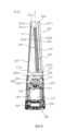
首先將描述送風機1的整體結構。圖1顯示送風機1的整體外觀。First, the overall structure of the
參見圖1,送風機1可以可替代地稱為或實現為空氣調節機、空氣淨化風扇、或空氣清淨機,空氣被吸入其中並且所吸入的空氣在其中循環。Referring to FIG. 1 , the
根據本發明一實施例的送風機1可以包括:吸入模組或組件100,以透過其吸入空氣;以及送風模組或組件200,以透過其排出吸入的空氣。The
送風機1可以具有直徑向上或朝送風模組200減小的圓柱或圓錐形狀,並且送風機1整體可以具有圓錐或截頭圓錐的形狀。隨著橫截切面及/或重量朝底部增大,重心可能會降低,從而降低傾翻的風險。然而,將該橫截切面配置為朝頂部變窄是沒有必要的。The
吸入模組100的橫截切面可以具有頂部逐漸減小的面積或直徑。送風模組200之橫截切面還可以具有朝頂部逐漸減小的面積或直徑。送風模組200可以設置在吸入模組100上方,並且吸入模組100和送風模組200的直徑可以配置為使過渡看起來平滑或無縫。The cross-section of the suction module 100 may have a top tapering area or diameter. The cross-section of the air supply module 200 may also have a gradually decreasing area or diameter toward the top. The air supply module 200 may be disposed above the suction module 100, and the diameters of the suction module 100 and the air supply module 200 may be configured to make the transition look smooth or seamless.
吸入模組100可以包括:驅動單元500;下殼體120,設置在驅動單元500上方;以及過濾器130,設置在下殼體120內部。The suction module 100 may include: a driving
驅動單元500可以安置在地面、地板、或其他表面上,並可以支撐送風機1其餘部分的重量。下殼體120和過濾器130可以放置在驅動單元500的上側。The
下殼體120的外形可以是圓錐形(或者可替代地是圓柱形),並且其中設置有過濾器130的空間可以形成在下殼體120內部。下殼體120可以具有吸入口121,其向下殼體120的內部開口。複數個吸入口121可以沿下殼體120的圓周表面形成。The outer shape of the
過濾器130的外形可以是圓柱形(或者可替代地是圓錐形)。含在通過吸入口121引入的空氣中的異物可以被過濾器130過濾。The outer shape of the
送風模組200可以具有穿透中間部分的狹槽或開口,以便看起來是分離的且具有垂直延伸的兩列。該狹槽或開口可以界定稍後更詳細描述的送風空間S。送風模組200可以包括彼此間隔開的第一塔架或延伸部220;以及第二塔架或延伸部230。送風模組200可以包括塔架基座或連接器210,以將第一塔架220和第二塔架230連接至吸入模組100。塔架基座210可以位於吸入模組100上側的上方,並可以設置在第一塔架220和第二塔架230的下側。The blower module 200 may have a slot or opening through the middle portion so as to appear separated and have two columns extending vertically. This slot or opening may define a supply air space S described in more detail later. The blower module 200 may include a first tower or
塔架基座210的外形可以是圓錐形(或者可替代地是圓柱形),並且塔架基座210可以設置在吸入模組100的上表面上,以形成與吸入模組100連續的外圓周表面。The outer shape of the
塔架基座210的上表面211(以下稱為塔架基座上表面211)可以向下凹陷以形成向前和向後延伸的凹部或凹槽。第一塔架220可以從塔架基座上表面211的第一側211a(例如,左側)向上延伸,而第二塔架230可以從塔架基座上表面211的第二側211b(例如,右側)向上延伸。The upper surface 211 of the tower base 210 (hereinafter referred to as the tower base upper surface 211 ) may be recessed downward to form a recess or groove extending forward and rearward. The
塔架基座210可以分配自吸入模組100內部供應之過濾的空氣,並將分配的空氣提供至第一塔架220和第二塔架230。The
塔架基座210、第一塔架220、以及第二塔架230可以製成為單獨的部件,或者可替代地一體化製造。塔架基座210和第一塔架220可以形成送風機1的第一連續外圓周表面,而塔架基座210和第二塔架230可以形成送風機1的第二連續外圓周表面。
作為圖1所示之實施例的替代方案,第一塔架220和第二塔架230可以在沒有塔架基座210的情況下,直接地組裝至吸入模組100,或者可以與吸入模組100一體製造。As an alternative to the embodiment shown in FIG. 1 , the
第一塔架220和第二塔架230可以彼此間隔開,並且送風空間S可以形成在第一塔架220與第二塔架230之間。The
送風空間S可以理解成第一塔架220與第二塔架230之間的空間,其具有敞開的前側、後側、以及上側。The air supply space S can be understood as the space between the
包含第一塔架220、第二塔架230、以及送風空間S的送風模組200的外形可以是圓錐形(或者可替代地是圓柱形)。The shape of the air supply module 200 including the
分別形成在第一塔架220和第二塔架230中的第一排出口222和第二排出口232可以朝送風空間S排放空氣。The first and
第一塔架220和第二塔架230可以相對應送風空間S而彼此對稱地設置,使得氣流均勻地分佈在送風空間S中,從而有利於控制水平氣流和上升氣流。The
第一塔架220可以包括第一塔架殼體221,以形成第一塔架220的外形,而第二塔架230可以包括第二塔架殼體231,以形成第二塔架230的外形。 塔架基座210、第一塔架殼體221、以及第二塔架殼體231可以稱為上殼體,其設置在下殼體120上方,並具有第一排出口222和第二排出口232,空氣通過該些排出口排出。由塔架基座210、第一塔架殼體221、以及第二塔架231界定的下殼體120可以與上殼體統稱為“殼體”。The
第一排出口222可以形成在第一塔架220中以垂直地延伸,而第二排出口232可以形成在第二塔架230中以垂直地延伸。The
從第一塔架220和第二塔架230排出空氣的流動方向可以形成在前後方向上。A flow direction of air exhausted from the
可由第一塔架220與第二塔架230之間的距離界定的送風空間S的寬度可以在垂直方向上是不變的。可替代地,送風空間S的寬度可以在垂直方向上增加或減小。The width of the blowing space S, which may be defined by the distance between the
藉由使送風空間S的寬度沿垂直方向為不變,可以使流向送風空間S前方的空氣在垂直方向上均勻地分佈。By keeping the width of the air supply space S constant in the vertical direction, the air flowing in front of the air supply space S can be evenly distributed in the vertical direction.
如果送風空間S上側的寬度與送風空間S下側的寬度不同,則較寬側的流速可能低於較窄側的流速,並且在垂直方向上可能會出現速度偏差。當在垂直方向出現空氣流速的偏差時,所供應的乾淨空氣量可能會根據空氣排出的垂直位置而有所變化。If the width of the upper side of the air supply space S is different from the width of the lower side of the air supply space S, the flow velocity on the wider side may be lower than that on the narrower side, and velocity deviation may occur in the vertical direction. When there is a deviation in the air velocity in the vertical direction, the amount of clean air supplied may vary depending on the vertical position of the air discharge.
分別從第一排出口222和第二排出口232排出的空氣可以在送風空間S內結合之後供應給使用者。The air respectively discharged from the
從第一排出口222排出的空氣和從第二排出口232排出的空氣可以不單獨地流向使用者,而是可以在送風空間S內結合或混合之後供應給使用者。The air discharged from the
間接氣流由於排放至送風空間S的空氣可以形成在送風機1周圍的空氣中,使得送風機1周圍的空氣也可以流向送風空間S。The indirect air flow can be formed in the air around the
由於第一排出口222排出的空氣和第二排出口232排出的空氣在送風空間內彼此結合,因此可以提高所結合之排出空氣的平直度或穩定性。藉由將所排出的空氣匯合在送風空間S內,還可以促使第一塔架220和第二塔架230周圍的空氣沿送風模組200的外圓周表面向前流動。Since the air discharged from the
第一塔架殼體221可以包括:第一塔架上端221a,形成第一塔架220的上表面;第一塔架前端221b,形成第一塔架220的前表面;第一塔架後端221c,形成第一塔架220的後表面;第一外壁221d,形成第一塔架220的外圓周表面;以及第一內壁221e,形成面對送風空間S的第一塔架220的內表面。The first tower housing 221 may include: a first tower
相似地,第二塔架殼體231可以包括:第二塔架上端231a,形成第二塔架230的上表面;第二塔架前端231b,形成第二塔架230的前表面;第二塔架後端231c,形成第二塔架230的後表面;第二外壁231d,形成第二塔架230的外圓周表面;以及第二內壁231e,形成面對送氣空間S的第二塔架230的內表面。Similarly, the second tower shell 231 may include: a second tower
第一外壁221d和第二外壁231d可以在 ta徑向上形成以向外凸出彎曲,使得第一塔架220和第二塔架230各自的外圓周表面彎曲。The first
第一內壁221e和第二內壁231e可以在徑向上形成以朝送風空間S向內凸出彎曲,使得第一塔架220和第二塔架230各自的內圓周表面彎曲。The first
第一排出口222可以形成在第一內壁221e中並在垂直方向上延伸。第一排出口222可以在徑向上向內敞開。第二排出口232可以形成在第二內壁231e中並在垂直方向上延伸。第二排出口232可以在徑向上向內敞開。The
第一排出口222可以位於相較於第一塔架前端221b更靠近第一塔架後端221c。第二排出口232可以位於相較於第二塔架前端231b更靠近第二塔架後端231c。The
第一板狹縫223可以形成在第一內壁221e中以垂直延伸。第二板狹縫233可以形成在第二內壁231e中以垂直延伸。第一板狹縫223和第二板狹縫233可以在徑向上形成向內敞開。稍後將描述的第一氣流轉換器401(參見圖6)可以穿過第一板狹縫223,並且稍後描述的第二氣流轉換器402(參見圖6)可以穿過第二板狹縫233。The first plate slit 223 may be formed in the first
第一板狹縫223可以位於相較於第一塔架後端221c更靠近第一塔架前端221b。 第二板狹縫233可以相較於第二塔架後端231c更靠近第二塔架前端231b。第一板狹縫223和第二板狹縫233可以彼此面對。The
在下文中,將參見圖2和圖3描述送風機1的內部結構。圖2是圖1中所示沿P-P’線所截取之送風機1的剖面圖;以及圖3是圖1中所示沿Q-Q’線所截取之送風機1的剖面圖。Hereinafter, the internal structure of the
參見圖2,可以在驅動單元500上側設置用於控制風扇組件300和加熱器240操作的基體組件或控制器150(例如,印刷電路板或PCB組件)。可以在驅動單元500上側上形成控制空間150s,其中設置有基體組件150。Referring to FIG. 2 , a base assembly or a controller 150 (for example, a printed circuit board or PCB assembly) for controlling operations of the
過濾器130可以設置在控制空間150s上方。過濾器130可以具有中空圓柱狀,並且圓柱狀的過濾器孔131或中空開口可以形成在過濾器130內部。The
通過吸入口121引入的空氣可以穿過過濾器130並流向過濾器孔131。Air introduced through the suction port 121 may pass through the
吸入網格140可以設置在過濾器130上方。向上流過過濾器130的空氣可以穿過吸入網格140。吸入網格140可以設置在風扇組件300與過濾器130之間。當下殼體120被卸下並且過濾器130與送風機1分離時,吸入網格140可以避免使用者的手接觸風扇組件300。The
風扇組件300可以設置在過濾器130的上側上,並可以對送風機1外的空氣產生吸力。The
藉由驅動風扇組件300,送風機1外部環境的空氣可以依序地通過吸入口121和過濾孔131吸入,以流向第一塔架220和第二塔架230。By driving the
可以在過濾器130與送風模組200之間形成加壓空間300s,風扇組件300設置在其中。A
第一分配空間220s可以形成在第一塔架220內部,且第二分配空間230s可以形成在第二塔架230內部。通過加壓空間300s的空氣可以向上流動通過第一分配空間220s或第二分配空間230s。塔架基座210可以將穿過加壓空間300s的空氣分配至第一分配空間220s和第二分配空間230s中。塔架基座210可以形成將第一塔架220和第二塔架230與風扇組件300連接的通道。The
第一分配空間220s可以形成在第一外壁221d與第一內壁221e之間。第二分配空間230s可以形成在第二外壁231d與第二內壁231e之間。The
第一塔架220可以包括第一導流件或空氣引導件224,其引導空氣在第一分配空間220s內部的流向。 複數個第一導流件224可以設置為彼此垂直間隔開。The
第一導流件224可以形成以從第一塔架後端221c朝第一塔架前端221b突出。第一導流件224可以在前後方向上與第一塔架前端221b間隔開。第一導流件224可以斜向地向下延伸,同時向前方推進。複數個第一導流件224中的每一個向下傾斜的角度可以隨著第一導流件224的向上推進而減小。The
第二塔架230可以包括第二導流件或空氣引導件234,其引導空氣在第二分配空間230s內部的流向。複數個第二導流件234可以設置為彼此垂直間隔開。The
第二導流件234可以形成以從第二塔架後端231c朝第二塔架前端231b突出。第二導流件234可以在前後方向上與第二塔架前端231b間隔開。第二導流件234可以斜向地向下延伸,同時在向前方推進。複數個第二導流件234中的每一個向下傾斜的角度可以隨著第二導流件234向上推進而減小。The
第一導流件224可以引導從風扇組件300排出的空氣流向第一排出口222。第二導流件234可以引導從風扇組件300排出的空氣流向第二排出口232。The
參見圖3,風扇組件300可以包括:風扇馬達310,其產生動力;馬達殼體330,其容納風扇馬達310;風扇320,其藉由接收來自風扇馬達310的動力而旋轉;以及擴散器340,其引導被風扇320加壓的空氣的流向。Referring to FIG. 3 , the
風扇馬達310可以設置在風扇320的上側,並且可以透過從風扇馬達310向下延伸的馬達軸311連接至風扇320。The
馬達殼體330可以包括:第一或上馬達殼體331,覆蓋風扇馬達310的上部;以及第二或下馬達殼體332,覆蓋風扇馬達310的下部。The
第一排出口222可以設置在塔架基座210的上側上。 第一排出口下端222d可以接合於或設置在塔架基座上表面211的上側。The
第一排出口222可以與第一塔架上端221a的下側間隔開。第一排出口上端222c可以形成為與第一塔架上端221a的下側間隔開。The
第一排出口222可以在垂直方向上斜向地延伸以傾斜。第一排出口222可以在向上行進的同時向前傾斜。第一排出口222可以相對於在垂直方向上延伸的垂直軸線Z斜向地向後延伸。The
第一排出口前端222a和第一排出口後端222b可以在垂直方向斜向地延伸,並且可以彼此平行地延伸。第一排出口前端222a和第一排出口後端222b可以相對於在垂直方向延伸的垂直軸線Z向後傾斜。The first discharge port
第一塔架220可以包括第一排放引導件225,以將第一分配空間220s內部的空氣引導至第一排出口222。The
第一塔架220可以相對於送風空間S與第二塔架230對稱,並可以具有與第二塔架230相同的形狀和結構。上述第一塔架220的描述可以相同地應用於第二塔架230。The
送風機1可以包括加熱器240,設置在上殼體的內部。可以設置複數個加熱器240以分別對應於第一排出口222和第二排出口232。加熱器240可以包括:第一加熱器241,設置在第一塔架220中;以及第二加熱器242,設置在第二塔架230中。第一加熱器241可以在垂直方向上斜向地或者成一定角度設置,以與第一排出口222相對應或對齊,而第二加熱器242可以在垂直方向上斜向地或者以一定角度設置,以與第二排出口232相對應或對齊。The
加熱器240可以基於切換模式電源供應(SMPS)方法由電源供應裝置供電。加熱器240可以從外部電源接收電力,並加熱通過排出口222、232排出至送風空間S的空氣。The
在下文中,將參見圖4和圖5描述用於引起附壁效應之送風機1的排氣結構。圖4顯示從頂部至底部俯視送風機1的形式;以及圖5顯示沿圖1所示之沿R-R'線所截取的送風機1並仰視的形式。Hereinafter, the exhaust structure of the
參見圖4,由於第一內壁221e和第二內壁231的凸面曲率,第一內壁221e與第二內壁231e之間的距離可以隨著更接近送風空間S時減小。Referring to FIG. 4 , due to the convex curvature of the first
第一內壁221e和第二內壁231e可以形成為朝徑向內部凸出,並且第一內壁221e和第二內壁231e的頂點或中心之間可以形成最短或中心距離D0。最短距離D0可以在送風空間S的中心形成。The first
第一排出口222和第二排出口232可以在最短距離D0形成的位置後面形成。The
第一塔架前端221b和第二塔架前端231b可以以第一或前部距離D1間隔開。第一塔架後端221c和第二塔架後端231c可以以第二或後部距離D2間隔開。The first tower
第一距離D1和第二距離D2可以相同,但是本文所揭露的實施例並不受到限制。第一距離D1可以大於最短距離D0,且第二距離D2可以大於最短距離D0。The first distance D1 and the second distance D2 may be the same, but the embodiments disclosed herein are not limited thereto. The first distance D1 may be greater than the shortest distance D0, and the second distance D2 may be greater than the shortest distance D0.
第一內壁221e與第二內壁231e之間的距離可以從後端221c、231c至形成最短距離D0的位置而減小,且可以從形成最短距離D0的位置至前端221b、231b而增加。The distance between the first
第一塔架前端221b和第二塔架前端231b可以形成為相對於前後軸線X傾斜或彎曲。The first tower
分別繪製在第一塔架前端221b和第二塔架前端231b的正切線相對於前後軸線X可以具有特定傾斜角A。The tangent lines drawn respectively at the first tower
通過送風空間S向前排出的一些空氣可以以相對於前後軸線X的傾斜角A流動。Some of the air discharged forward through the blowing space S may flow at an inclination angle A with respect to the front-rear axis X. FIG.
由於第一內壁221e和第二內壁231e的此種彎曲結構,通過送風空間S向前排出的空氣的擴散角可以增加。Due to such a curved structure of the first
當空氣通過送風空間S向前排出時,可以將稍後將描述的第一氣流轉換器401帶入第一板狹縫223中。When air is discharged forward through the blowing space S, a
當空氣通過送風空間S向前排出時,可以將稍後將描述的第二氣流轉換器402帶入第二板狹縫233中。When air is discharged forward through the blowing space S, a second
參見圖5,藉由第一排放引導件225和第二排放引導件235,可以沿一流動方向引導朝送風空間S排放的空氣。Referring to FIG. 5 , by the
第一排放引導件225可以包括:第一內部引導件225a,連接至第一內壁221e;以及第一外部引導件225b,連接至第一外壁221d。The
第一內部引導件225a可以與第一內壁221e一體製造,或者可替代地可以單獨地製造且隨後進行組合。The first
第一外部引導件225b可以與第一外壁221d一體製造,或者可替代地可以單獨地製造且隨後進行組合。The first
第一內部引導件225a可以形成以從第一內壁221e朝第一分配空間220s突出。The first
第一外部引導件225b可以形成以從第一外壁221d朝第一分配空間220s突出。第一外部引導件225b可以形成為與第一內部引導件225a間隔開,並可在第一內部引導件225a與第一外部引導件225b之間形成第一排出口222。The first
第一內部引導件225a的曲率半徑可以小於第一外部引導件225b的曲率半徑。The radius of curvature of the first
第一分配空間220s中的空氣可以在第一內部引導件225a與第一外部引導件225b之間流動,並可以通過第一排出口222流入送風空間S中。The air in the
第二排放引導件235可以包括:第二內部引導件235a,連接至第二內壁231e;以及第二外部引導件235b,連接至第二外壁231d。The second discharge guide 235 may include: a second
第二內部引導件235a可以與第二內壁231e一體製造,或者可替代地可以單獨製造且隨後進行組合。The second
第二外部引導件235b可以與第二外壁231d一體製造,或者可替代地可以單獨製造且隨後進行組合。The second
第二內部引導件235a可以形成以從第二內壁231e朝第二分配空間230s突出。The second
第二外部引導件235b可以形成以從第二外壁231d朝第二分配空間230s突出。第二外部引導件235b可以形成為與第二內部引導件235a間隔開,並可以在第二內部引導件235a與第二外部引導件235b之間形成第二排出口232。The second
第二內部引導件235a的曲率半徑可以小於第二外部引導件235b的曲率半徑。The radius of curvature of the second
第二分配空間230s中的空氣可以在第二內部引導件235a與第二外部引導件235b之間流動,並可以通過第二排出口232流入送風空間S中。The air in the
第一排出口222的寬度可以形成以從第一排放引導件225的進氣口(其可以是第一排出口222的進氣口222i)朝第一排放引導件225的出氣口(其可以是第一排出口222的出氣口222o)於前進時逐漸地減小然後再增加。The width of the
進氣口222i的入口寬度W1可以大於出氣口222o的出口寬度W3。The inlet width W1 of the air inlet 222i may be greater than the outlet width W3 of the air outlet 222o.
入口寬度W1可以界定為第一內部引導件225a的外端與第一外部引導件225b的外端之間的距離。出口寬度W3可以界定為第一排出口前端222a與第一排出口後端222b之間的距離,其中第一排出口前端222a是第一內部引導件225a的內端,而第一排出口後端222b是第一外部引導件225b的內端。The entrance width W1 may be defined as the distance between the outer end of the first
入口寬度W1和出口寬度W3可以分別大於第一排出口222的最短寬度或內部寬度W2。The inlet width W1 and the outlet width W3 may be greater than the shortest width or the inner width W2 of the
最短寬度W2可以界定為第一排出口後端222b與第一內部引導件225a之間的最短距離。The shortest width W2 may be defined as the shortest distance between the first discharge port
第一排出口222的寬度可以從第一排放引導件225的進氣口逐漸地減小至形成最短寬度W2的位置,並可以從形成最短寬度W2的位置至第一排放引導件225的出氣口逐漸地增加。The width of the
類似於第一排放引導件225,第二排放引導件235可以具有:第二排出口前端232a以及第二排出口後端232b。第二排放引導件235可以具有與第一排放引導件225相同的寬度分佈或配置。Similar to the
由於附壁效應,通過第一排出口222排出至送風空間S的空氣可以沿第一內壁221e的內表面向前流動。由於附壁效應,通過第二排出口232排出至送風空間S的空氣可以沿第二內壁231e的內表面向前流動。Due to the Coanda effect, the air discharged into the blowing space S through the
在下文中,將參見圖6和圖7描述氣流轉換器400所引起的風向改變。圖6是顯示氣流轉換器400突出至送風空間S中使得送風機1形成向上氣流的形式的示意圖;以及圖7是顯示氣流轉換器400之操作原理的示意圖。Hereinafter, a change in the wind direction caused by the air flow converter 400 will be described with reference to FIGS. 6 and 7 . FIG. 6 is a schematic diagram showing a form in which the airflow converter 400 protrudes into the air supply space S so that the
參見圖6,氣流轉換器400可以朝送風空間S突出,並可以將通過送風空間S向前排出的氣流轉換成上升的風。Referring to FIG. 6 , the airflow converter 400 may protrude toward the blowing space S, and may convert the airflow discharged forward through the blowing space S into ascending wind.
氣流轉換器400可以包括:第一氣流轉換器401,設置在第一塔架殼體221;以及第二氣流轉換器402,設置在第二塔架殼體231。The airflow converter 400 may include: a
第一氣流轉換器401和第二氣流轉換器402與第一塔架220和第二塔架230分別地耦接(例如插入),並從第一塔架220和第二塔架230朝送風空間S突出,以阻擋送風空間S的前部。The
當第一氣流轉換器401和第二氣流轉換器402突出以阻擋送風空間S的前部時,通過第一排出口222和第二排出口232排出的空氣可以在Z方向向上流動。When the
第一氣流轉換器401和第二氣流轉換器402可以配置成經由第一板狹縫223和第二板狹縫233分別插入或拉至第一塔架220和第二塔架230內部。 當第一氣流轉換器401和第二氣流轉換器402分別帶入或拉至第一塔架220和第二塔架230中以打開送風空間S的前部時,通過第一排出口222和第二排出口232排出的空氣可以通過送風空間S朝X方向向前流動。作為一替代方案,第一氣流轉換器401和第二氣流轉換器402可以配置為可從第一板狹縫223和第二板狹縫233移除(例如,透過提起或拉動)拆卸下來。作為另一替代方案,第一氣流轉換器401和第二氣流轉換器402可以可拆卸地耦接至第一塔架殼體221和第二塔架殼體231的內壁221e和231e。The
參見圖7,第一氣流轉換器401和第二氣流轉換器402可以各自包括:板410,朝送風空間S突出;馬達420,對板410提供驅動力以移動板410;板引導件430,用以引導板410的移動方向;以及蓋440,用以支撐馬達410和板引導件430。Referring to FIG. 7, the
在下文中,以第一氣流轉換器401為例進行描述,但是下述之關於第一氣流轉換器401的描述可以等同地應用於第二氣流轉換器402。In the following, the
如圖4和圖5所示,可以將板410帶入第一板狹縫223中。當驅動馬達420時,板410可以透過第一板狹縫223突出至送風空間S中。板410可以彎曲以具有弧形。當驅動馬達420時,板410可以在彎曲或圓周方向移動,以突出至送風空間S中。As shown in FIGS. 4 and 5 , the
馬達420可以連接至小齒輪421以使小齒輪421旋轉。馬達420可以使小齒輪421以順時針或逆時針旋轉。A
板引導件430可以具有一個垂直延伸的板狀。板引導件430可以包括引導狹縫450,其基於圖7於向右方向(或可替代地,於向左方向)向上傾斜。 板引導件430可以包括齒條431,形成以朝小齒輪421突出並與小齒輪421嚙合。The
當馬達420驅動且小齒輪421旋轉時,與小齒輪421嚙合的齒條431可以垂直地移動。When the
引導突起或旋鈕411可以形成在板410中,以朝板引導件430突出。引導突起411可以插入引導狹縫450中。A guide protrusion or
當板引導件430根據齒條431的垂直移動而垂直地移動時,引導突起411可以透過界定引導狹縫450的板引導件430邊緣壓在引導突起411而移動。根據板引導件430的垂直移動,引導突起411可以在引導狹縫450內對角地移動。When the
當齒條431向上移動時,引導突起411可以沿引導狹縫450移動,以位於引導狹縫450的最下端(也如同在圖7中的最左端)中。當引導突起411位於引導狹縫450的最下端時,板410可以完全地隱藏在第一塔架220內,如圖4和圖5所示。當齒條431向上移動時,引導縫隙450也會向上移動。因此,引導突起411可以沿引導狹縫450在相同的水平面上於圓周方向上移動。When the
當齒條431向下移動時,引導突起411可以沿引導狹縫450移動,以位於引導狹縫450的最上端(也如同在圖7中的最右端)中。當引導突起411位於引導狹縫450的最上端時,板410可以從第一塔架220朝送風空間S突出,如圖6所示。當齒條431向下移動時,引導縫隙450也會向下移動。 因此,引導突起411可以沿引導狹縫450在相同的水平面上於著圓周方向上移動。When the
蓋440可以包括:第一蓋441,設置在板引導件430外側;第二蓋442,設置在板引導件430內部,並與第一內壁221e接觸;馬達支撐板443,從第一蓋441向上延伸並連接至馬達420;以及止動器444,用以限制板引導件430的垂直移動。The
第一蓋441可以覆蓋板引導件430的外側,而第二蓋442可以覆蓋板引導件430的內部。第一蓋441可以將其中設置有板引導件430的空間與第一分配空間220s隔開。第二蓋442可以避免板引導件430接觸第一內壁221e。The
馬達支撐板443可以從第一蓋441向上延伸,以支撐馬達420的負荷。The
止動器444可以形成以從第一蓋441朝板引導件430突出。鎖定突起可以形成在板引導件430的表面上,且該鎖定突起可以配置為根據板引導件430的垂直移動被止動器444卡住。當板引導件430垂直地移動時,該鎖定突起可以被止動器444卡住,使得可以限制板引導件430的垂直移動。A
在下文中,將參見圖8和圖9描述吸入模組100的內部結構。圖8是在送風機1的縱向剖面視圖上吸入模組100的內部放大示意圖;以及圖9是顯示過濾器130的支撐結構的示意圖。Hereinafter, the internal structure of the suction module 100 will be described with reference to FIGS. 8 and 9 . 8 is an enlarged schematic view of the inside of the suction module 100 on a longitudinal sectional view of the
風扇組件300可以包括風扇殼體350,風扇320容納在其中。The
風扇殼體350可以包括喇叭口141,其將穿過過濾器130的空氣引導至風扇320中。Fan housing 350 may include bell mouth 141 that directs air passing through
喇叭口141可以設置在過濾器130上方,並且吸入網格140可以設置在過濾器130與喇叭口141之間。The bell mouth 141 may be disposed above the
喇叭口141可以具有預定內徑(BD)的環形,並且其內部可以在垂直方向開口。內徑(BD)可以理解為喇叭口141的內圓周表面141a的直徑,而朝風扇320的氣流路徑可以形成在喇叭口141內部。The bell mouth 141 may have a ring shape with a predetermined inner diameter (BD), and the inside thereof may be opened in a vertical direction. The inner diameter (BD) may be understood as the diameter of the inner circumferential surface 141 a of the bell mouth 141 , and the airflow path toward the
連接至馬達軸311的風扇320藉由旋轉而對過濾器孔131中的空氣產生抽吸力,並且過濾器孔131的空氣可以通過吸入網格140和喇叭口141流入風扇殼體350中。The
過濾器130可以具有其中形成過濾器孔131的圓柱狀,並且通過吸入口121被引入下殼體120中的空氣可以藉由通過過濾器130的外圓周表面130a與內圓周表面130b之間流入過濾器孔131中。引入下殼體120中的空氣可以在從過濾器130的外圓周表面130a流向過濾器130的內圓周表面130b的同時,在被設置在過濾器130的外圓周表面130a與內圓周表面130b之間的預過濾器、高效率粒子空氣濾器、或除臭過濾器去除所含異物的狀態下,流入過濾器孔131中。The
過濾器130可以由過濾器框架132支撐,而過濾器框架132限制過濾器130在徑向向外方向上移動。過濾器框架132可以在垂直方向上延伸,並可以與過濾器130的外圓周表面130a接觸。複數個過濾器框架132可以設置為在圓周方向上間隔開,並可以設置三個。過濾器130可以透過其中沒有設置過濾器框架132的區域而進入/退出。下殼體120可以設置為可拆卸地附接至驅動單元500,並且使用者可以卸下下殼體120,接著拉出過濾器130以進行清潔。The
過濾器框架132可以連接至設置在過濾器130下方的基體殼體160。基體殼體160可以與過濾器130的下表面接觸以支撐過濾器130。基體殼體160可以包括殼體外壁161,其在圓周方向上延伸並由驅動單元500、600、和700支撐。The filter frame 132 may be connected to a
殼體外壁161包括:殼體外壁上表面161a,沿圓周方向延伸;框架連接部161b,從殼體外壁上表面161a向上突出;以及框架緊固孔161c,形成在框架連接部161b上。The case
過濾器框架132可以透過穿過框架緊固孔161c的預定緊固構件(圖未顯示)連接至殼體外壁161,並可以固定至基體殼體160。The filter frame 132 may be connected to the case
用於旋轉送風機1的驅動單元500、600、700設置在基體殼體160下方。驅動單元500、600、700包括:基座510、610、和760,與地面接觸;以及旋轉板520和620,可旋轉地設置在基座510、610、和760上側。The
基體殼體160可以設置在旋轉板520和620上方,並且在旋轉板520和620支撐基體殼體160和設置在基體殼體160上側的所有結構的負荷的同時進行旋轉。The
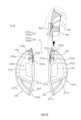
在下文中,將參見圖10描述根據本發明第一實施例的驅動單元500的外部結構。圖10是在組裝有基座510和旋轉板520的驅動單元500的立體圖。Hereinafter, an external structure of a
驅動單元500包括:基座510;旋轉板520,連接至下殼體120,並可旋轉地設置在基座510的上側;以及馬達530,產生動力以旋轉旋轉板520。The driving
基座510可以與地面接觸並可以穩定地放置在地面上,且可以具有碗形。The base 510 may be in contact with the ground and may be stably placed on the ground, and may have a bowl shape.
旋轉板520被設置以便可在基座510的上方旋轉,並由基座510支撐。當旋轉板520旋轉時,基座510可以支撐由設置在包含有旋轉板520的基座510上側的所有結構所產生的正向應力和剪切應力。The
旋轉板520可以設置以覆蓋基座510上部,並包括:第一座架部521,其上安置基體殼體160;以及第二座架部522,其上安置下殼體120。The
第一座架部521和第二座架部522可以一體成形,並且第一座架部521和第二座架部522可以藉由在第一座架部521與第二座架部522之間形成的第一階梯部520d而彼此區分開來。第一座架部521相較於第二座架部522可以形成為更加向上突出,並且第一階梯部520d可以在垂直方向上具有一高度且在圓周方向上延伸。The
第一座架部521包括:中心部520a,其中形成有軸通孔520s1;第一邊緣520b,形成以圍繞中心部520a;第二邊緣520c,形成以圍繞第一邊緣520b;以及第一階梯部520d,從第二邊緣520c向下突出。The
中心部520a的整體外形可以是盤形,並且在垂直方向上開口的軸通孔520s1可以形成在中心部520a中。軸通孔520s1可以是稍後將描述的軸本體570(參見圖11)插入的空間。形成以面對彼此的一對頂部520a1可以形成在軸通孔520s1中。頂部520a1可以是藉由將中心部520a部分地浸沒在軸通孔520s1中而形成的區域,並且軸通孔520s1可以具有藉由頂部520a1徑向地向內突出的一部分。The overall shape of the
第一邊緣520b的整體外形可以是環形,並可以沿中心部520a的外圓周連接至中心部520a。第一邊緣520b的上表面相較於中心部520a的上表面可以形成為更加向下彎曲。The overall shape of the
第二邊緣520c的整體外形可以是環形,並可以沿第一邊緣520b的外圓周連接至第一邊緣520b。第二邊緣520c的上表面相較於第一邊緣520b的上表面可以形成為更加向上彎曲。因此,第一邊緣520b可以理解為在中心部520a與第二邊緣520c之間向下凹入的區域。The overall shape of the
第一階梯部520d的整體外形可以是圓柱形,並且其橫截切面的形狀可以是環形。第一階梯部520d可以沿第二邊緣520c的外圓周向下突出,並可以在圓周方向上延伸。第一座架部521可以藉由第一階梯部520d與第二座架部522垂直地間隔開。The overall shape of the first stepped
第二座架部522包括:第三邊緣520e,連接至第一階梯部520d;第二階梯部520f,從第三邊緣520e向下突出;彎曲部520g,連接至第二階梯部520f;以及邊緣520h,連接至彎曲部520g。The second mount portion 522 includes: a
第三邊緣520e的整體外形可以是環形,並可以沿第一階梯部520d的外圓周連接至第一階梯部520d。第三邊緣520e可以從第一階梯部520d的下端徑向地向外突出,並可以在圓周方向上延伸。第三邊緣520e可以位於第二邊緣520c下方。The overall shape of the
第二階梯部520f可以形成以從第三邊緣520e的外圓周向下突出,並可以在圓周方向上延伸。第三邊緣520e可以藉由第二階梯部520f與彎曲部520g垂直地間隔開。The second stepped
第一階梯部520d和第二階梯部520f可以稱為在旋轉板520的上表面上形成為彎曲的“階梯部”。The first stepped
彎曲部520g可以形成以從第二階梯部520f的外圓周在徑向向外方向上突出,並可以在圓周方向上延伸。彎曲部520g可以在徑向向外方向上至少向下彎曲一次。彎曲部520g可以界定為第二階梯部520f與邊緣520h之間的區域。The
邊緣520h可以形成旋轉板520的最外側。邊緣520h可以從彎曲部520g的外圓周在徑向向外方向上突出,並可以在圓周方向上延伸。邊緣520h的下表面可以與基座510的上表面接觸並由基座510支撐。The
上突起部529可以從旋轉板520的上表面向上突出。複數個上突起部529可以形成為在圓周方向上間隔開,並可以從第二邊緣520c的上表面向上突出。上突起部529可以連接至基體殼體160,以將基體殼體160固定至旋轉板520。基體殼體160透過穿透上突起部529的預定緊固構件(圖未示出)固定至旋轉板520,並藉由旋轉板520的旋轉與旋轉板520一體旋轉。The
馬達530可以設置在蓋520上方。在旋轉板520上,可以形成在垂直方向上開口的馬達插入凹槽520s2,並且在馬達530下部區域的一部分插入馬達插入凹槽520s2中的狀態下,馬達530可以由旋轉板520支撐。馬達插入凹槽520s2可以形成在第二邊緣520c,並可以形成在複數個上突起部529之間。在馬達530的至少一部分插入馬達插入凹槽520s2中的狀態下,藉由旋轉板520的旋轉,馬達530可以與旋轉板520一體地旋轉。由於馬達530設置在旋轉板520上方且一起旋轉,因此可以減小驅動單元500的垂直高度,因而可以更緊密地製造驅動單元500。The
馬達530的整體外形可以是圓柱形。馬達530可以包括電線連接部531,形成以突出至馬達530的外部並電性連接至電線590。當馬達530與旋轉板520一體旋轉時,為了避免電線連接部531被移位,複數個上突起部529中的任何一個即為止動器突起部529a。止動器突起部529a可以具有與上突起部529相同的形狀,並可以界定為上突起部,其位於與電線連接部531相鄰處。止動器突起部529a可以位於電線連接部531的旋轉半徑內,並且電線連接部531可以在旋轉的同時被止動器突起部529a卡住。The overall shape of the
可以在旋轉板520上形成殼體緊固孔520e2,連接至下殼體120的預定緊固構件(圖未示出)穿透該殼體緊固孔520e2。殼體緊固孔520e2可以形成為在第三邊緣520e中垂直地開口,並且複數個殼體緊固孔520e2可以在圓周方向上形成為間隔開。殼體緊固孔520e2可以形成在後續將描述的下突起部528處(參見圖13),並且預定緊固構件(圖未示出)穿過殼體緊固孔520e2以將下殼體120連接至旋轉板520。下殼體120連接至旋轉板520,並可以藉由旋轉板520的旋轉與旋轉板520一體旋轉。A case fastening hole 520e2 through which a predetermined fastening member (not shown) connected to the
第一階梯部520d可以在圓周方向上延伸,並且至少一部分可以在徑向向內方向上形成為彎曲。第一階梯部520d可以在徑向向內方向上形成為彎曲以形成谷部520d1。谷部520d1可以形成凹槽520e1,其垂直地在第一階梯部520d與第三邊緣520e之間開口。在下殼體120處,可以形成用於與旋轉板520相連接的突起(圖未示出),並且該突起(圖未示出)被插入凹槽520e1中,使得下殼體120可以固定至旋轉板520。然而,下殼體120可以透過殼體緊固孔520e2連接至旋轉板520,並可以不形成谷部520d1和凹槽520e1。The first stepped
第一階梯部520d和第二階梯部520f對旋轉板520給予在徑向方向上延伸的高度分佈,因此第一階梯部520d和第二階梯部520f可以為將在後續描述之要放置在旋轉板520內部的軸承580(參見圖13)提供空間。The first stepped
在下文中,將參見圖11描述根據本發明第一實施例的基座510的結構。圖11是顯示驅動單元500分解成基座510和旋轉板520並從頂部至底部觀看的形式的示意圖。Hereinafter, the structure of the base 510 according to the first embodiment of the present invention will be described with reference to FIG. 11 . FIG. 11 is a schematic diagram showing a form in which the
基座510包括:主幹511,形成內部空間並與地面接觸;以及頂板512,覆蓋主幹511的內部空間並設置在主幹511的上側。The
主幹511的整體外觀可以是碗形,並可以在其內部形成空間。The overall appearance of the trunk 511 may be bowl-shaped, and a space may be formed inside it.
頂板512的整體外形可以是盤形,並可以安置在主幹511的上表面上。The overall shape of the top plate 512 may be a disk, and may be placed on the upper surface of the trunk 511 .
頂板512包括:第一支撐部512a,安置在主幹511上;第二支撐部512b,連接至第一支撐部512a;第三支撐部512d,連接至第二支撐部512b;以及架座512e,從第三支撐部512d向上突出。該些支撐部512a、512b、和512d及架座512e可以一體成形。The top plate 512 includes: a first support portion 512a, placed on the trunk 511; a second support portion 512b, connected to the first support portion 512a; a third support portion 512d, connected to the second support portion 512b; The third support portion 512d protrudes upward. The supporting parts 512a, 512b, and 512d and the stand 512e can be integrally formed.
第一支撐部512a的整體外形可以是環形,並可以形成頂板512的邊緣。第一支撐部512a的下表面與主幹511的上表面接觸,且頂板512可以由主幹511支撐。The overall shape of the first supporting portion 512 a may be ring-shaped, and may form an edge of the top plate 512 . A lower surface of the first support part 512 a is in contact with an upper surface of the trunk 511 , and the top plate 512 may be supported by the trunk 511 .
第二支撐部512b的整體外形可以是環形,並可以形成以從第一支撐部512a的內圓周在徑向向內方向上突出,並可以在圓周方向上延伸。第一支撐部512a和第二支撐部512b可以由稍後將描述的軌道513來區分。The overall shape of the second support part 512b may be annular, and may be formed to protrude in a radially inward direction from the inner circumference of the first support part 512a, and may extend in a circumferential direction. The first support part 512a and the second support part 512b may be distinguished by a
第三支撐512d的整體外形可以是環形,並可以形成以從第二支撐部512b的內圓周在徑向向內方向上突出,並可以在圓周方向上延伸。第三支撐部512d可以界定為稍後將描述的邊界壁514的內部區域。The overall shape of the third support 512d may be ring-shaped, and may be formed to protrude in a radially inward direction from the inner circumference of the second support part 512b, and may extend in a circumferential direction. The third support part 512d may be defined as an inner area of the boundary wall 514 which will be described later.
架座512e的整體外形可以是圓柱形,並可以形成以從第三支撐部512d的上表面向上突出。軸本體570可以穿過架座512e的中心部分,並且軸本體570可以可旋轉地設置在架座512e的中心部分上。The overall shape of the stand 512e may be cylindrical, and may be formed to protrude upward from the upper surface of the third support part 512d. The
基座510可以具有從基座510向上突出的軌道513。軌道513可以在圓周方向上延伸以形成圓形的閉環。The base 510 may have a
軌道513的整體外形可以是環形,並且稍後將描述的軸承580和680(參見圖13和圖18)可以由軌道513接收移動路徑。另外,由於軸承580和680的旋轉由軌道513支撐,所以可以避免軸承580和680從該移動路徑中移位。The overall shape of the
基座510可以包括邊界壁514,形成以從基座510的上表面向上突出。The base 510 may include a boundary wall 514 formed to protrude upward from an upper surface of the
邊界壁514的整體外形可以是圓柱形,並可以在圓周方向上延伸以在內部形成空間514s。邊界壁514可以形成以從頂板512的上表面向上突出,並可以基於邊界壁514區分第二支撐部512b和第三支撐部512d。邊界壁514可以形成在軌道513的徑向內部,並可以形成在稍後將描述的旋轉軸殼體515的徑向外側。The overall shape of the boundary wall 514 may be cylindrical, and may extend in a circumferential direction to form a space 514s inside. The boundary wall 514 may be formed to protrude upward from the upper surface of the top plate 512 , and the second support part 512 b and the third support part 512 d may be distinguished based on the boundary wall 514 . The boundary wall 514 may be formed radially inside of the
驅動單元500包括:第一齒輪540,連接至馬達530;以及第二齒輪550,與第一齒輪540嚙合。The driving
馬達530可以設置在旋轉板520上方,並且第一齒輪540可以設置在旋轉板520下方。第一齒輪540可以是正齒輪或小齒輪。The
第二齒輪550可以設置為安置在基座510上,並可以徑向設置在第一齒輪540內部。在第二齒輪550的徑向上的外側處,第一齒輪540可以與第二齒輪550嚙合地旋轉。第二齒輪550可以是環形齒輪並可以沿圓周方向延伸。The
第二齒輪550可以連接至邊界壁514。第二齒輪550可以與邊界壁514的外圓周表面接觸,並可以附接至或固定至邊界壁514的外圓周表面。因此,第二齒輪550處於穩固的狀態,並且當第一齒輪540與第二齒輪550嚙合並旋轉時,第一齒輪540和連接至第一齒輪540的馬達530可以與旋轉板520一體旋轉。The
第二齒輪550可以設置在軌道513與軸本體570之間。第二齒輪550可以設置在軌道513與邊界壁514之間。由於此種配置結構,邊界壁514的內部空間514s可以緊密地用為用於佈置和支撐軸本體570的空間。The
基座510可以包括旋轉軸殼體515,朝旋轉板520突出。The base 510 may include a rotation shaft housing 515 protruding toward the
旋轉軸殼體515的整體外形可以是圓柱形,並且旋轉軸殼體515可以提供軸本體570可以其中的空間。旋轉軸殼體515可以形成以從架座512e的上表面向上突出,並可以形成以面對邊界壁514的內圓周表面。The overall shape of the rotation shaft housing 515 may be cylindrical, and the rotation shaft housing 515 may provide a space in which the
稍後將描述的軸軸承560(參見圖13)可以設置在旋轉軸殼體515內部。旋轉軸殼體515可以支撐軸軸承560,以防止軸軸承560和軸本體570從旋轉中心移位。A shaft bearing 560 (see FIG. 13 ), which will be described later, may be provided inside the rotary shaft housing 515 . The rotating shaft housing 515 may support the shaft bearing 560 to prevent the shaft bearing 560 and the
在下文中,將參見圖12描述軸本體570的詳細結構以及軌道513和第二齒輪550及軸本體570之間的相對位置關係。圖12是顯示從頂部至底部觀看如圖11中所示的基座510的結構。Hereinafter, the detailed structure of the
軸插入孔510s1形成在旋轉軸殼體515內部,軸本體570穿過該軸插入孔510s1,並且在後續將描述的軸支架526插入該軸插入孔510s1中。軸插入孔510s1可以界定向上及向下開口的空間,並可以界定在旋轉軸殼體515內部的圓柱形空間。A shaft insertion hole 510s1 through which the
軸本體570可以向上穿過軸插入孔510s1。軸本體570可以被設置使得其下部設置在基座510內部,而其上部穿過軸插入孔510s1。The
軸本體570包括:第一本體571,彎曲地延伸;第二本體572,設置為與第一本體571間隔開;以及第三本體573,設置為分別與第一本體571和第二本體572間隔開。第一本體571、第二本體572、以及第三本體573可以設置為在軸插入孔510s1中彼此間隔開。The
基於圖12,第一本體571可以設置在第二本體572和第三本體573的前面,並且第一本體571相較於第二本體572和第三本體573可以延伸更長。第二本體572和第三本體573可以設置以在前方向上面對第一本體571,並且第二本體572和第三本體573在左右方向上彼此面對。第二本體572可以設置在左側,而第三本體573可以設置在右側,但是第二本體572和第三本體573可以具有相同的形狀。Based on FIG. 12 , the first body 571 may be disposed in front of the second body 572 and the third body 573 , and the first body 571 may extend longer than the second body 572 and the third body 573 . The second body 572 and the third body 573 may be disposed to face the first body 571 in a front direction, and the second body 572 and the third body 573 face each other in a left and right direction. The second body 572 may be disposed on the left side, and the third body 573 may be disposed on the right side, but the second body 572 and the third body 573 may have the same shape.
第二本體572和第三本體573可以彼此相連接以具有與第一本體571相同的形狀。軸本體570可以包括具有相同形狀的兩個第一本體571,並且兩個第一本體571可以間隔開,以便在前後方向上彼此面對。The second body 572 and the third body 573 may be connected to each other to have the same shape as the first body 571 . The
第一本體571延伸為在水平方向上彎曲,並可以沿該延伸方向彎曲三次。第一本體571包括:左端部571a,其向後斜向地延伸;右端部571c,其向後斜向地延伸;以及核心部571b,其向前延伸為分別從左端部571a和右端部571c彎曲。The first body 571 is extended to be bent in a horizontal direction, and may be bent three times along the extending direction. The first body 571 includes: a left end portion 571a extending obliquely rearward; a right end portion 571c extending obliquely rearward; and a core portion 571b extending forwardly to be bent from the left end portion 571a and the right end portion 571c, respectively.
第二本體572延伸為在水平方向上彎曲,並可以沿該延伸方向彎曲一次。第二本體572包括斜向地向前延伸的一個端部572a;以及從該一個端部572a延伸為彎曲的另一端部572b。The second body 572 is extended to be bent in a horizontal direction, and may be bent once along the extending direction. The second body 572 includes one end portion 572a extending obliquely forward; and the other end portion 572b extending from the one end portion 572a to be bent.
第三本體573延伸為在水平方向中彎曲,並可以沿該延伸方向彎曲一次。第三本體573包括斜向地向前延伸的一個端部573a;以及從該一個端部573a延伸為彎曲的另一端部573b。第二本體572和第三本體573可以具有相同的形狀和結構。The third body 573 is extended to be bent in a horizontal direction, and may be bent once along the extending direction. The third body 573 includes one end portion 573a extending obliquely forward; and the other end portion 573b extending from the one end portion 573a to be curved. The second body 572 and the third body 573 may have the same shape and structure.
在第一本體571與第二本體572之間及在第一本體571與第三本體573之間可以形成電線穿過部570s,後續將描述的電線590穿過該電線穿過部570s(參見圖15),電線590可以透過捲軸574(參見圖15)插入軸本體570中,此將在後面描述。電線590可以穿過電線穿過部570s並向上延伸,並可以電性連接至馬達530。電線穿過部570s可以界定為軸本體570的內部空間,包含有旋轉板520的旋轉中心O。由於電線590沿旋轉中心O向上延伸並連接至馬達530,因此在旋轉板520旋轉的同時,電線590不會產生扭曲,並可以順利地維持馬達530與電線590之間的電性連接。A
在基座510的上側上,隨著從旋轉中心O徑向地向外移動,旋轉軸殼體515、邊界壁514、第二齒輪550、以及軌道513以該順序進行設置。由於軌道513設置在第二齒輪550外側,因此在軸承580移動的期間,第二齒輪並不會與第二齒輪550互相干擾。另外,由於第二齒輪550在軌道513內部與第一齒輪540嚙合,因此第二齒輪550可以確保與軸承580間具有足夠的距離。另外,由於第二齒輪550在軌道513內部與第一齒輪540嚙合,因此會減小第一齒輪540與第二齒輪550之間的動力傳遞路徑的距離,從而使動力的損失最小化。On the upper side of the
軌道513、第二齒輪550、以及軸本體570可以設置在相同的水平面上。更具體地,上述結構513、550、以及570可以設置以垂直地穿透一預定水平面,該預定水平面包含基座510的上表面並垂直於該垂直軸線。此可以被不同地表達為:軌道513、第二齒輪550、以及軸主體570設置以垂直地穿透包含有頂板512上表面的水平面。由於此種結構,軌道513與邊界壁514之間的空間被用為第二齒輪550的佈置空間,並且邊界壁514的內部空間被用為軸本體570的佈置空間。因此,軌道513、第二齒輪550、以及軸本體570可以全部設置在單一個水平面上。因此,可以減小驅動單元500在垂直方向上所佔據的高度,從而可以減小下殼體120與地面向上隔開的高度。另外,由於可以降低吸入口121的位置,因此可以通過吸入口121有效地吸入積聚在地面上的灰塵。The
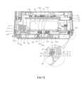
在下文中,將參見圖13描述根據本發明第一實施例的旋轉板520的詳細配置。圖13是顯示驅動單元500分解成基座510和旋轉板520並從底部至頂部視角觀看的形式。Hereinafter, the detailed configuration of the
主幹511可以包括:下板511a,其與地面接觸;主幹外壁511b,從下板511a的邊緣斜向地向上延伸;以及主幹座架部511c,從主幹外壁511b的上端徑向地向外延伸。The trunk 511 may include: a lower plate 511a in contact with the ground; a trunk outer wall 511b extending obliquely upward from an edge of the lower plate 511a; and a trunk mount portion 511c extending radially outward from an upper end of the trunk outer wall 511b.
下板511a的整體外形可以是盤形,並且複數個孔511s可以在圓周方向上形成為彼此間隔開,用於固定基座510上的部件的緊固構件(圖未示出)插入該些孔511s中。The overall shape of the lower plate 511a may be a disk shape, and a plurality of holes 511s may be formed spaced apart from each other in the circumferential direction, and fastening members (not shown) for fixing components on the
主幹外壁511b可以在圓周方向延伸並可以形成為在徑向上向外傾斜。The trunk outer wall 511b may extend in the circumferential direction and may be formed to be inclined radially outward.
主幹座架部511c可以在圓周方向上延伸,並可以面對設置在上側上的旋轉板520的邊緣520h。當旋轉板520安置在基座510上時,邊緣520h可以安置並支撐在主幹座架部511c的上表面上。The trunk mount part 511c may extend in the circumferential direction, and may face the
旋轉板520可以包括第一周壁523,在圓周方向上延伸;第二周壁524,在第一周壁523內部的圓周方向上延伸;以及第三周壁525,在第二周壁524內部的圓周方向上延伸。The
第一周壁523、第二周壁524、以及第三周壁525可以具有同心關係,並且當它們設置在徑向向外方向上時,它們的直徑可以增大。The first
第一周壁523、第二周壁524、以及第三周壁525可以藉由切割至少一部分來形成,且第一齒輪540可以設置在切割掉該些周壁523、524、和525的區域。The first
第一齒輪540可以透過驅動馬達軸532連接至馬達530,並且驅動馬達軸532和第一齒輪540可以設置在馬達插入凹槽520s2下方。The
旋轉板520可以包括軸支架526,從中心部520a向下突出,並提供軸本體570插入其中的空間。軸支架526的整體外形可以是圓柱形,並且軸插入凹槽520s1可以形成在軸支架526內部。The
軸支架526包括:支架外壁526a,形成軸支架526的外形;脊部526b,從支架外壁526a徑向地向內突出;以及本體緊固構件526c,插入脊部526b中。The shaft bracket 526 includes: a bracket
本體緊固構件526c可以插入形成在脊部526b並在垂直方向上開口的本體緊固孔(圖未示出)中。The
軸本體570可以插入軸支架526中並固定至軸支架526,且脊部526b的曲率可以形成以分別對應於軸本體570的第一本體571、第二本體572、以及第三本體573。在將軸本體570插入軸支架526中的同時,藉由將本體緊固構件526c穿透軸本體570和脊部526b,使軸本體570固定旋轉板520。因此,軸本體570可以與旋轉板520一體旋轉,並使軸本體570的結構簡化,且軸本體570的結構可以使軸本體570與基座510之間的干擾最小化。The
驅動單元500可以包括設置以圍繞軸本體570的軸軸承560。The driving
軸軸承560的整體外形可以是圓柱形,並且軸本體570可以穿透軸軸承560內部。The overall shape of the shaft bearing 560 may be cylindrical, and the
軸軸承560可以包括:第一層561,設置以可與軸支架526一體旋轉;以及第二層562,設置以圍繞第一層561。The shaft bearing 560 may include: a
第一層561可以徑向地設置在第二層562內部,並且第一層561的外圓周表面可以與第二層562的內圓周表面接觸。The
第二層562可以設置在旋轉軸殼體515內部,並且第二層562的外圓周表面可以與旋轉軸殼體515的內圓周表面接觸。The
第一層561可以可旋轉地連接至第二層562,並且當旋轉板520旋轉時,其可以與軸支架526一起旋轉。另一方面,第二層562可以固定地設置在旋轉軸殼體515,並且即使當旋轉板520旋轉時也可以不旋轉。第一層561可以支撐軸支架526的旋轉,而第二層562可以支撐第一層561的旋轉。因此,可以在第一層561與第二層562之間注入潤滑油。The
軸軸承560可以設置在旋轉板520以圍繞軸支架526的支架外壁526a,或者可以設置在基座510以固定至旋轉軸殼體515的內表面。The shaft bearing 560 may be provided at the
旋轉板520可以包括下突起部528,從第二座架部522向下突出。複數個下突起部528可以在圓周方向上形成為彼此間隔開,並且在垂直方向上開口的殼體緊固孔520e2可以形成在下突起部528上。The
旋轉板520可以包括在徑向方向上延伸的複數個凸條527。複數個凸條527可以在圓周方向上形成為彼此間隔開。The
凸條527可以包括:第一凸條527a,從邊緣520h朝第一周壁523延伸;第二凸條527b,從第一周壁523朝第二周壁524延伸;以及第三凸條527c,從第二周壁524朝第三周壁525延伸。The convex lines 527 may include: a first convex line 527a extending from the
凸條527可以包括:第一邊界凸條527d,其設置在該些周壁523、524、和525的切割部,並在徑向方向上延伸;以及第二邊界凸條527e,設置在該些周壁523、524、和525的切割部,並在圓周方向上與第一邊界凸條527d間隔開。The convex lines 527 may include: a first boundary
第一邊界凸條527d可以理解為單一的凸條527d,其中第二凸條527b和第三凸條527c彼此連接以形成一連續表面。第一邊界凸條527d可以在徑向方向上延伸,並可以設置相鄰於第一齒輪540的一側。The
第二邊界凸條527e可以理解為單一的凸條527e,其中第二凸條527b和第三凸條527c彼此連接以形成一連續表面,且第二邊界凸條527e可以在圓周方向上與第一邊界凸條527d間隔開,並設置相鄰於第一齒輪540的另一側。The
第一齒輪540設置在第一邊界凸條527d與第二邊界凸條527e之間,並可在第一邊界凸條527d與第二邊界凸條527e之間旋轉。The
凸條527可以包括第四凸條527f,從第三周壁525內部徑向地延伸。第四凸條527f可以位於第四周壁521a與第五周壁521b之間。第四周壁521a可以從第一座架部521的下表面突出。第五周壁521b可以從第一座架部521的下表面突出並與第四周壁521a間隔開。第四周壁521a和第五周壁521b可以具有環形,並且複數個第四凸條527f可以沿圓周方向形成為彼此間隔開。The protrusions 527 may include fourth protrusions 527f radially extending from the inside of the third
旋轉板520包括複數個軸承580,佈置為沿旋轉板520的圓周方向彼此間隔開,並可旋轉地支撐在基座510上。滾筒可以作為一種軸承580使用。The
軸承580可以在圓周方向上設置在間隔開的複數個凸條527之間,並可以設置在複數個第一凸條527a之間。The
軸承580可以在徑向方向上設置在彼此間隔開的邊緣520h與第一周壁523之間。The
軸承580可以包括:支撐突起581,形成以從旋轉板520向下突出;支撐軸582,連接至支撐突起581;以及輪子583,支撐軸582穿過該輪子583。The
支撐突起581可以具有插入孔(圖未示出),支撐軸582插入杆插入孔中,並且支撐軸582可以向上插入支撐突起581。The
支撐軸582可以支撐輪子583。螺釘或銷釘可以用為一種支撐軸582。支撐軸582可以插入並固定至支撐突起581中,並可以支撐輪子583,使得輪子583不會向下被移除。The
輪子583可以設置為在支撐突起581與支撐軸582之間為可旋轉的。滾珠軸承或滾筒可以用為一種輪子583。可以使用支撐軸582作為旋轉軸來旋轉輪子583。A
當旋轉板520旋轉時,輪子583可以使用支撐軸582作為旋轉軸來旋轉,並可以基於旋轉中心O在圓周方向上移動。此可以不同地表達:輪子583使用支撐軸582作為旋轉軸來旋轉,並圍繞旋轉中心O繞轉。When the
軸本體570可以提供繞轉軸線P,以在垂直方向上延伸,並穿過旋轉中心O,且支撐軸582可以提供旋轉軸線Q,以在垂直方向上延伸。繞轉軸線P和旋轉軸線Q可以並排形成。當旋轉板520旋轉時,軸承580可以繞著旋轉軸線Q旋轉,且同時在圓周方向上繞著繞轉軸線P移動。The
在下文中,將參見圖14描述根據本發明第一實施例的軸承580的詳細結構和佈置。圖14顯示從底部至頂部視角觀察的旋轉板520的形狀。Hereinafter, the detailed structure and arrangement of the
用於佈置第一齒輪540的切割部520s3可以形成在第一邊界凸條527d與第二邊界凸條527e之間。切割部520s3可以理解為該些周壁523、524、和525被切割掉的部分。A cutting part 520s3 for arranging the
第一齒輪540可以設置以便在切割部520s3內部可旋轉的,並且從邊緣520h朝第一齒輪540延伸的加強凸條527a1、527a2、以及527a3可以形成在切割部520s3。加強凸條527a1、527a2、以及527a3可以具有與第一凸條527a相同的形狀。在切割部520s3可以形成突起部支撐部529b,以連接至止動器突起部529a並向下延伸。The
複數個軸承580可以設置為在圓周方向上彼此間隔開,並且五個軸承580可以設置為彼此間隔開。然而,軸承580的數量不限定於上述,只要複數個軸承580設置為彼此間隔開就足夠。A plurality of
複數個軸承580可以包括:第一軸承580a,基於旋轉中心O相對於驅動馬達軸532設置;第二軸承580b,設置在驅動馬達軸532與第一軸承580a之間;以及第三軸承580c,設置在第一軸承580a與第二軸承580之間。第一軸承580a、第二軸承580b、以及第三軸承580c的區別是根據複數個軸承580的佈置位置來分類。該些軸承580a、580b、580c各自的形狀和結構可以相同。The plurality of
第一軸承580a可以基於旋轉中心O相對於驅動馬達軸532設置。第一軸承580的支撐軸582、驅動馬達軸532、以及旋轉中心O可以位於中心線(CL)上。然而,如果第一軸承580a相對於旋轉中心O設置在與驅動馬達軸532相對的位置處就足夠,則並不一定必須設置在中心線CL上。The
由於第一軸承580a之如上述的佈置,因距離驅動馬達軸532的距離最遠而使旋轉板520上支撐較弱的區域可以被第一軸承580a穩定地支撐。Due to the arrangement of the
以旋轉中心O為中心且在第二軸承580b與第一齒輪540之間的分離角可以是銳角。以旋轉中心O為中心且在驅動馬達軸532與支撐軸582之間的分離角可以是銳角。第二軸承580b可以包括:一側的軸承580b1,設置相鄰於第一邊界凸條527d;以及另一側的軸承580b2,設置相鄰於第二邊界凸條527e,並且該一側的軸承580b1和該另一側的軸承580b2可以相對於驅動馬達軸532而對稱地設置。.The separation angle between the
由於第二軸承580b之如上佈置,所以可以補充未形成該些周壁523、524、和525的切割部520s3的弱剛性。此外,藉由將第二軸承580b放置在與切割部520s3相鄰處,能盡量抑制由設置在切割部520s3中並與第二齒輪550嚙合的第一齒輪540旋轉時所產生的振動。Due to the arrangement of the
第三軸承580c可以包括:一側的軸承580c1,與第一軸承580a的一側間隔開;以及另一側的軸承580c2,與第一軸承580a的另一側間隔開,並且該一側的軸承580c1和該另一側的軸承580c2可以相對於驅動馬達軸532而對稱地設置。The
第一齒輪540可以由在軸承580的徑向內部處與第二齒輪550嚙合旋轉,此表示第一距離R1,即從旋轉中心O至驅動馬達軸532的距離,小於第二距離R2,即從旋轉中心O至支撐軸582的距離。The
由於上述的結構,會減小從驅動馬達軸532至旋轉中心O的動力傳遞路徑的距離,從而可以提高動力能效。同時,藉由將軸承580佈置在第一齒輪540外側,可以有效降低由第一齒輪540旋轉產生的振動。此外,藉由將軸承580佈置為盡可能地靠近邊緣520h,使在旋轉板520上側旋轉的重型結構的負荷可以在徑向方向上均勻地分佈。Due to the above structure, the distance of the power transmission path from the
旋轉板520可以包括上架座520i,連接至基體殼體160。上架座520i可以形成以從旋轉板520的下表面向下突出。上架座520i可以包括:架座本體520i1,在該些凸條527之間延伸;以及架座孔520i2,在架座本體520i1處垂直地形成為開口。旋轉板520可以透過穿透架座孔520i2的預定緊固構件(圖未示出)連接至基體殼體160。The
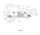
在下文中,將參見圖15描述根據本發明第一實施例的基座510的內部結構以及基座510與旋轉板520、基體殼體160、及下殼體120之間的連接關係。圖15是在送風機1的縱向剖面視圖上驅動單元500的一部分的放大視圖。Hereinafter, the internal structure of the
用於容納基體152和153的控制空間150s形成在基體殼體160內部。基體152和153可以包括:第一基體152,用於控制驅動單元500、氣流轉換器400、以及風扇組件300;以及第二基體153(參見圖20),其控制加熱器240的驅動。A
馬達530的至少一部分可以設置在基體殼體160的控制空間150s中。馬達530可以在基體殼體160內部旋轉。At least a part of the
由於基體152和153以及馬達530一起設置在基體殼體160的控制空間150s中,所以可以實現電子元件的集成管理。Since the
基體殼體160可以包括第一磁性構件169,其從殼體外壁161徑向地向外突出。下殼體120可以包括第二磁性構件129,其具有與第一磁性構件169極性相反的極性。下殼體120可以藉由第一磁性構件169和第二磁性構件129的磁力與基體殼體160分離。The
殼體外壁161可以包括:緊固部161d,其從殼體外壁161的下端徑向地向外延伸;以及支撐部161e,其從緊固部161d的外端向下延伸。緊固部161d可以安裝在第三邊緣520e上,並藉由穿過殼體緊固孔520e1的緊固構件(圖未示出)固定至旋轉板520。在此種情況下,支撐部161e可以安置在邊緣520h上,並由邊緣520h支撐。與本實施例不同的是,穿透殼體緊固孔520e1的緊固構件(圖未示出)可以直接地連接至下殼體120而不是基體殼體160,使得下殼體120連接至旋轉板520並固定至旋轉板 520。The case
在基座510內部,可以形成其中插入有軸本體570的空間510s2,並且空間510s2可以形成在主幹511內部。Inside the
軸本體570可以包括:第一本體571,設置在旋轉軸殼體515中;捲軸574,連接至第一本體571,並設置在第一本體571下方,且容納在基座510中;以及緊固板576,其在徑向上突出,並連接至軸支架 526。The
捲軸574可以設置在旋轉軸殼體515下方,並可以具有圓柱形,其中電線穿過部570s形成於其內。緊固板576可以從捲軸574的上部徑向地向內延伸,並且本體緊固構件526c可以穿透緊固板576和脊部526b,以將軸本體570固定至旋轉板520。The
從外部電源(圖未示出)接收電力的電線590可以沿捲軸574的外圓周表面纏繞預定次數。電線590可以透過形成在捲軸574內部的電線穿過部570s電性連接至馬達530。The
用於支撐纏繞電線590的捲軸軸承575可以設置在基座510內部。A reel bearing 575 for supporting the winding
在基座510與旋轉板520之間可以形成垂直間隔開的間隙G1。間隙G1可以理解為在沿旋轉板520下表面延伸的第一線L1與沿基座510上表面延伸的第二線L2之間的空間。A vertically spaced gap G1 may be formed between the base 510 and the
在基座510與軸承580之間可以形成垂直間隔開的間隙G2。間隙G2可以理解為在沿基座510上表面延伸的第二線L2與沿軸承580下表面延伸的第三線L3之間的空間。軸承580的一部分可以與基座510接觸,而其餘部分可以與基座510上表面間隔開以形成間隙G2。A vertically spaced gap G2 may be formed between the base 510 and the
由於基座510直接支撐軸承580,因此可以形成間隙G1和G2。軸承580可以安置在軌道513從基座510向上突出的上側,並可以在沿軌道513在旋轉板520的旋轉方向上延伸的圓周方向上移動。旋轉板520的下表面可以與基座510的上表面間隔開,而不與基座510的上表面接觸,並且旋轉板520藉由安置在軌道513上的軸承580由基座510旋轉地支撐。Since the base 510 directly supports the
當軸承580在安置在向上突出的軌道513上的同時而旋轉時,旋轉板520和軸承580會在維持有間隙G1和G2的同時進行旋轉。因此,可以避免驅動單元500由於旋轉所產生的摩擦而受到磨損。When the
軸承580的支撐軸582可以在徑向上設置在軌道513的外側。軸承580的內部可以由軌道513支撐。由於軸承580的支撐軸582設置在導軌513的外側,因此送風機1的負荷可以在徑向上均勻地分佈。The
在下文中,將參見圖10至圖15描述根據本發明第一實施例的驅動單元500的操作動作。Hereinafter, the operation actions of the
當馬達530透過電線590所提供的電力而使驅動馬達軸532旋轉時,連接至驅動馬達軸532的第一齒輪540也會旋轉。第二齒輪550可以固定至邊界壁514,並且第一齒輪540沿第二齒輪550於圓周方向上延伸的外圓周旋轉。當第一齒輪540旋轉時,旋轉板520會以軸本體570作為旋轉軸而在圓周方向上旋轉。當旋轉板520旋轉時,旋轉板520的旋轉由軸軸承560支撐,其中軸軸承560的至少一部分與軸支架526一起旋轉。當旋轉板520旋轉時,軸承580會使用旋轉軸線Q作為旋轉軸而旋轉,同時,軸承580會在圓周方向上圍繞繞轉軸線P移動。當軸承580安置在從基座510向上突出的軌道513時,可以在圓周方向移動並可以由軌道513支撐。When the
藉由上述的支撐結構,在圓周方向上彼此間隔開並直接由基座510支撐的複數個軸承580可以將送風機1的重量負荷均勻地分配至設置在地面上的基座510,並藉由分散送風機1的重量負荷,可以穩定地支撐送風機1的旋轉。With the support structure described above, the plurality of
此外,由於軸承580使用旋轉軸線Q作為旋轉軸旋轉並支撐送風機1本體的負荷,因此避免軸承580與基座510表面之間由摩擦力所引起的磨損,並且軸承580的壽命可以延長。In addition, since the
在下文中,將參見圖16描述根據本發明第二實施例的基座610的結構。圖16是顯示在根據本發明第二實施例的驅動單元600分解為基座610和旋轉板620之後從上方觀察驅動單元600的示意圖。Hereinafter, the structure of a base 610 according to a second embodiment of the present invention will be described with reference to FIG. 16 . 16 is a schematic view showing the driving unit 600 viewed from above after the driving unit 600 is disassembled into a base 610 and a rotating plate 620 according to the second embodiment of the present invention.
基座610可以包括:主幹611,其內部形成空間並與地面接觸;以及頂板612,設置在主幹611的上側並覆蓋主幹611的內部空間。由於主幹611和頂板612與根據本發明第一實施例的主幹511和頂板512相同,因此省略詳細的描述。The base 610 may include: a trunk 611 forming a space inside and in contact with the ground; and a top plate 612 disposed on an upper side of the trunk 611 and covering the interior space of the trunk 611 . Since the trunk 611 and the top plate 612 are the same as the trunk 511 and the top plate 512 according to the first embodiment of the present invention, detailed descriptions are omitted.
基座610可以具有從基座610向上突出的軌道613。軌道613包括:第一軌道613a,形成以從頂板612的上表面向上突出;以及第二軌道613b,形成在第一軌道613a的內部並面對第一軌道613a。The base 610 may have a rail 613 protruding upward from the base 610 . The rail 613 includes: a first rail 613a formed to protrude upward from the upper surface of the top plate 612; and a second rail 613b formed inside the first rail 613a and facing the first rail 613a.
第一軌道613a和第二軌道613b可以具有環形,並且第一軌道613a和第二軌道613b可以具有同心關係。後面將描述的軸承680(參見圖18)可以在第一軌道613a與第二軌道613b之間於圓周方向上滾動,並且第一軌道613a和第二軌道613b可以防止軸承680偏離旋轉路徑。The first rail 613a and the second rail 613b may have a ring shape, and the first rail 613a and the second rail 613b may have a concentric relationship. A bearing 680 (see FIG. 18 ) to be described later may roll in the circumferential direction between the first rail 613 a and the second rail 613 b, and the first rail 613 a and the second rail 613 b may prevent the bearing 680 from deviating from the rotation path.
基座610可以包括複數個邊界壁614,從基座610的上表面向上突出。The base 610 may include a plurality of boundary walls 614 protruding upward from the upper surface of the base 610 .
邊界壁614的整體外形可以是圓柱形,並可以在圓周方向上延伸以在內部形成空間614s。邊界壁614可以形成以從頂板612的上表面向上突出,並可以形成在軌道613內側,且可以形成在稍後將描述的旋轉軸殼體615的外側。The overall shape of the boundary wall 614 may be cylindrical, and may extend in a circumferential direction to form a space 614s inside. The boundary wall 614 may be formed to protrude upward from the upper surface of the top plate 612, and may be formed inside the rail 613, and may be formed outside the rotation shaft housing 615 which will be described later.
驅動單元600可以包括:第一齒輪640,連接至馬達630;以及第二齒輪650,與第一齒輪640嚙合。The driving unit 600 may include: a
馬達630可以設置在旋轉板620上方,並且第一齒輪640可以設置在旋轉板620下方。第一齒輪640可以是正齒輪或小齒輪。The
第二齒輪650可以設置為安置在基座610上,並可以設置在第一齒輪640內側。第一齒輪640可以在第二齒輪650的外側藉由嚙合第二齒輪650來旋轉。第二齒輪650可以是環形齒輪並可以沿圓周方向延伸。The
第二齒輪650可以連接至邊界壁614。第二齒輪650可以與邊界壁614的外圓周表面接觸,並可以附接並固定至邊界壁614的外圓周表面。因此,第二齒輪650處於穩固的狀態,且當第一齒輪640旋轉時,第一齒輪640可以與馬達630一體旋轉。The
第二齒輪650可以設置在軌道613與軸本體670之間。另外,第二齒輪650可以設置在軌道613與邊界壁614之間。由於此種配置結構,形成在邊界壁614內部的空間614s可以緊密地用為佈置支撐軸本體670結構的空間。The
基座610可以包括旋轉軸殼體615,朝旋轉板620突出。The base 610 may include a rotation shaft housing 615 protruding toward the rotation plate 620 .
旋轉軸殼體615的整體外形可以是圓柱形,並且旋轉軸殼體615可以提供軸本體670可以插入其中的空間。旋轉軸殼體615可以形成以面對邊界壁614的內圓周表面。The overall shape of the rotation shaft housing 615 may be cylindrical, and the rotation shaft housing 615 may provide a space into which the shaft body 670 may be inserted. The rotation shaft housing 615 may be formed to face the inner circumferential surface of the boundary wall 614 .
驅動單元600可以包括軸軸承660,設置以圍繞插入在軸通孔620s1的軸本體670中。The driving unit 600 may include a shaft bearing 660 disposed to surround the shaft body 670 inserted in the shaft through hole 620s1.
軸軸承660的整體外形可以是圓柱形,並且軸本體670可以穿過軸軸承660內部。The overall shape of the shaft bearing 660 may be cylindrical, and the shaft body 670 may pass through the inside of the shaft bearing 660 .
軸軸承660可以包括:第一層661,設置為可與軸支架626(參見圖18)一體旋轉;以及第二層662,設置以圍繞第一層661。The shaft bearing 660 may include: a first layer 661 provided to be integrally rotatable with the shaft support 626 (see FIG. 18 ); and a second layer 662 provided to surround the first layer 661 .
第一層661可以設置在第二層662內部,並且第一層661的外圓周表面可以與第二層662的內圓周表面接觸。The first layer 661 may be disposed inside the second layer 662 , and an outer circumferential surface of the first layer 661 may be in contact with an inner circumferential surface of the second layer 662 .
第二層662可以設置在旋轉軸殼體615內部,並且第二層662的外圓周表面可以與旋轉軸殼體615的內圓周表面接觸。The second layer 662 may be disposed inside the rotation shaft housing 615 , and an outer circumferential surface of the second layer 662 may be in contact with an inner circumferential surface of the rotation shaft housing 615 .
第一層661可以可旋轉地連接至第二層662,並且當旋轉板620旋轉時,其可以與軸支架626一起旋轉。另一方面,第二層662可以固定地設置在旋轉軸殼體615,並且即使當旋轉板620旋轉時也可以不旋轉。第一層661可以支撐軸支架626的旋轉,並且第二層662可以支撐第一層661的旋轉。可以在第一層661與第二層662之間注入潤滑油。The first layer 661 may be rotatably connected to the second layer 662, and may rotate together with the shaft bracket 626 when the rotating plate 620 rotates. On the other hand, the second layer 662 may be fixedly provided to the rotation shaft housing 615 and may not rotate even when the rotation plate 620 rotates. The first layer 661 may support the rotation of the axle bracket 626 and the second layer 662 may support the rotation of the first layer 661 . Lubricating oil may be injected between the first layer 661 and the second layer 662 .
在下文中,參見圖17,將描述根據本發明第二實施例的軸本體670的詳細結構以及軌道613、第二齒輪650、和軸本體670之間的相對位置關係。圖17是顯示從頂部至底部角度觀看如圖16所示的基座610的示意圖。Hereinafter, referring to FIG. 17 , the detailed structure of the shaft body 670 according to the second embodiment of the present invention and the relative positional relationship among the rail 613 , the
軸插入孔610s1形成在第一層661內部,軸本體670穿透該軸插入孔610s1,並且稍後將描述的軸支架626插入其中。軸插入孔610s1可以界定為形成在向上及向下開口的基座610處的空間,並可以界定在第一層661內部的圓柱形空間。A shaft insertion hole 610s1 through which the shaft body 670 penetrates and into which a shaft bracket 626 to be described later is inserted is formed inside the first layer 661 . The shaft insertion hole 610s1 may define a space formed at the base 610 that is opened upward and downward, and may define a cylindrical space inside the first layer 661 .
軸本體670可以向上穿透軸插入孔610s1。軸本體670可以被設置使得下部設置在基座610內部,而上部穿過軸插入孔610s1。The shaft body 670 may penetrate upward through the shaft insertion hole 610s1. The shaft body 670 may be disposed such that a lower portion is disposed inside the base 610 and an upper portion passes through the shaft insertion hole 610s1.
軸本體670可以包括第一本體671,延伸為彎曲;第二本體672,設置為與第一本體671間隔開;以及第三本體673,設置以與第一本體671和第二本體672間隔開。第一本體671、第二本體672、以及第三本體673可以設置為在軸插入孔610s1中彼此間隔開。由於軸本體670與根據本發明第一實施例的軸本體570相同,因此將省略對其的詳細描述。The shaft body 670 may include a
在第一本體671與第二本體672之間以及在第一本體671與第三本體673之間可以形成電線穿過部670s,後續將描述的電線690穿過該電線穿過部670s(參見圖20)。電線690可以穿過電線穿過部670s並向上延伸,且可以電性連接至馬達630。電線穿過部670s可以界定為軸本體670的內部空間,其含有旋轉板620的旋轉中心O。由於電線690沿旋轉中心O向上延伸並連接至馬達630,因此即使在旋轉板620旋轉的同時,電線690也不會產生扭曲,並可以順利地維持馬達630與電線690之間的電性連接。A
在基座610的上側,隨著從旋轉中心O徑向地向外移動,軸軸承660、旋轉軸殼體615、邊界壁614、第二齒輪650、以及軌道613可以按照該順序一個接著一個地進行放置。On the upper side of the base 610, as moving radially outward from the rotation center O, the shaft bearing 660, the rotation shaft housing 615, the boundary wall 614, the
軌道613、第二齒輪650、以及軸本體670可以設置在相同的水平面上。更具體地,上述結構613、650、以及670可以設置在預定水平面上,其垂直於垂直線且包含基座610的上表面。由於其描述與本發明的實施例相同,因此將省略詳細的描述。The rail 613, the
在下文中,將參見圖18描述根據本發明第二實施例的旋轉板620的詳細配置。圖18是顯示在將根據本發明第二實施例的驅動單元600分解為基座610和旋轉板620之後,從底部至頂部觀察驅動單元600的示意圖。Hereinafter, the detailed configuration of the rotary plate 620 according to the second embodiment of the present invention will be described with reference to FIG. 18 . 18 is a schematic view showing the driving unit 600 viewed from bottom to top after the driving unit 600 according to the second embodiment of the present invention is disassembled into a base 610 and a rotating plate 620 .
主幹611可以包括:下板611a,其與地面接觸;主幹外壁611b,其從下板611a的邊緣斜向地向上延伸;以及主幹座架部611c,其從主幹外壁611b的上端徑向地向外延伸。The trunk 611 may include: a lower plate 611a in contact with the ground; a trunk outer wall 611b extending obliquely upward from an edge of the lower plate 611a; and a trunk mount portion 611c radially outward from an upper end of the trunk outer wall 611b. extend.
下板611a的整體外形可以是盤形,並且複數個孔611s在圓周方向上可以形成為彼此間隔開,用於固定基座610上的部件的緊固構件(圖未示出)插入該些孔611s中。The overall shape of the lower plate 611a may be a disc shape, and a plurality of holes 611s may be formed spaced apart from each other in the circumferential direction, and fastening members (not shown) for fixing components on the base 610 are inserted into the holes. 611s.
主幹外壁611b可以在圓周方向上延伸,並可以在徑向上形成為向外傾斜。The trunk outer wall 611b may extend in the circumferential direction, and may be formed to be inclined outward in the radial direction.
主幹座架部611c可以在圓周方向上延伸,並可以形成以面對旋轉板620的邊緣620h。當旋轉板620安置在基座610上時,邊緣620h可以安置並支撐在主幹座架部611c的上表面上。The trunk mount part 611c may extend in the circumferential direction, and may be formed to face the
旋轉板620可以包括:第一周壁623,其在圓周方向上延伸;第二周壁624,其在第一周壁623內側於圓周方向上延伸;以及第三周壁625,其在第二周壁624內側於圓周方向上延伸。The rotating plate 620 may include: a first
第一周壁623、第二周壁624、以及第三周壁625可以具有同心關係,並且當它們設置在徑向向外方向上時,直徑可以增大。The first
第一周壁623、第二周壁624、以及第三周壁625可以藉由切割至少一部分來形成,且第一齒輪640可以設置在該些周壁623、624、和625的切割部處。The first
第一齒輪640可以透過馬達軸632連接至馬達630,並且馬達軸632和第一齒輪640可以設置在馬達插入凹槽620s2下方。The
旋轉板620可以包括軸支架626,其提供軸本體670插入其中的空間。軸支架626的整體外形可以是圓柱形,並且軸插入凹槽620s1可以形成在軸支架626內部。The rotation plate 620 may include a shaft bracket 626 that provides a space into which the shaft body 670 is inserted. The overall shape of the shaft bracket 626 may be cylindrical, and a shaft insertion groove 620s1 may be formed inside the shaft bracket 626 .
軸支架626包括:支架外壁626a,形成軸支架626的外形;脊部626b,從支架外壁626a徑向向內突出;以及本體緊固孔626c,在脊部626b上於垂直方向上形成為開口。The shaft bracket 626 includes: a bracket
軸本體670可以插入軸支架626中並固定至軸支架626,並且脊部626b的曲率半徑與該些本體671、672、和673的形狀相匹配。在軸本體670插入軸支架626中的狀態下,預定緊固構件(圖未示出)穿過本體緊固孔626c以將軸本體670固定至旋轉板620。軸本體670可以與旋轉板620一體旋轉。因此,軸本體670可以簡化旋轉板620的旋轉軸結構,並且旋轉軸與基座610之間的干擾最小化。The shaft body 670 can be inserted into and fixed to the shaft bracket 626 , and the radius of curvature of the
旋轉板620可以包括下突起部628,形成以向下突出。複數個下突起部628可以在圓周方向上間隔開,並且下突起部628可以連接至殼體。The rotation plate 620 may include a lower protrusion 628 formed to protrude downward. A plurality of lower protrusions 628 may be spaced apart in a circumferential direction, and the lower protrusions 628 may be connected to the case.
旋轉板620可以包括在徑向方向延伸的複數個凸條627。複數個凸條627可以在圓周方向上以複數形成為彼此間隔開。The rotating plate 620 may include a plurality of protrusions 627 extending in a radial direction. The plurality of convex lines 627 may be formed in plural in the circumferential direction to be spaced apart from each other.
凸條627可以包括:第一凸條627a,其從邊緣620h朝第一周壁623延伸;第二凸條627b,其從第一周壁623朝第二周壁624延伸;以及第三凸條627c,其從第二周壁624朝第三周壁625延伸。該些凸條627a、627b、及627c中的每一個可以分別設置在於徑向方向上延伸的同一直線上。The convex strip 627 may include: a first convex strip 627a extending from the
凸條627可以包括:第一邊界凸條627d,設置在該些周壁623、624、和625被切割掉的部分,並在徑向上延伸;以及第二邊界凸條627e,設置在該些周壁623、624、和625被切割掉的部分,並在圓周方向上與第一邊界凸條627d間隔開。The ridges 627 may include: a
第一邊界凸條627d可以理解為單一的凸條627d,其中第一凸條627a、第二凸條627b、及第三凸條627c彼此連接以形成一連續表面。第一邊界凸條627d可以在徑向上延伸,並可以設置相鄰於第一齒輪640的一側。The
第二邊界凸條627e可以理解為單一的凸條627e,其中第一凸條627a、第二凸條627b、及第三凸條627c彼此連接以形成一連續表面。第二邊界凸條 627e 可以在圓周方向上與第一邊界凸條 627d間隔開,並設置相鄰於第一齒輪 640 的另一側。The
第一齒輪640設置在第一邊界凸條627d與第二邊界凸條627e之間,並可以在第一邊界凸條627d與第二邊界凸條627e之間旋轉。The
旋轉板620包括軸承680,其佈置為沿旋轉板620的圓周方向彼此間隔開,並可旋轉地支撐在基座610上。滾筒可以用為一種軸承680。The rotating plate 620 includes
軸承680可以設置在於圓周方向上設置為間隔開的複數個凸條627之間,並可以設置在複數個第二凸條627b之間。The
軸承680可以設置在於徑向上間隔開的該些周壁623、624、和625之間,並可以設置在第一周壁623與第二周壁624之間。The
當旋轉板620旋轉時,軸承680可以繞著後續將描述的支撐軸683(參見圖19)旋轉,並可以繞著旋轉中心O在圓周方向上移動。此可以不同地表達:軸承680使用支撐軸683作為旋轉軸來旋轉,並圍繞旋轉中心O繞轉。When the rotary plate 620 rotates, the bearing 680 can rotate around a support shaft 683 (see FIG. 19 ) which will be described later, and can move in a circumferential direction around a rotation center O. This can be expressed variously: the bearing 680 rotates using the
軸本體670在垂直方向延伸並可以提供穿過旋轉中心O的繞轉軸線P',且支撐軸683可以提供在徑向上延伸的旋轉軸線Q'。繞轉軸線P'和旋轉軸線Q'可以彼此垂直地延伸。當旋轉板620旋轉時,軸承680可以繞著旋轉軸線Q'旋轉,並同時沿繞轉軸線P'在圓周方向上移動。The shaft body 670 extends in a vertical direction and may provide a rotation axis P' passing through the rotation center O, and the
旋轉板620可以包括突起容納部620i,形成以向下突出。突起容納部620i可以形成凹槽520e1的下邊界,從下殼體120突出的突起(圖未示出)插入其中,並可以設置在複數個凸條627之間。突起容納部620i可以固定下殼體120的突起以將下殼體120固定至旋轉板620。但是,也可以不形成突起容納部620i,而僅藉由下突起部628來固定下殼體120。The rotation plate 620 may include a protrusion receiving part 620i formed to protrude downward. The protrusion receiving part 620i may form a lower boundary of the groove 520e1 into which a protrusion (not shown) protruding from the
在下文中,將參見圖19描述根據本發明第二實施例的軸承680的詳細結構和佈置。圖19顯示從底部至頂部視角觀察的旋轉板620的形狀。Hereinafter, the detailed structure and arrangement of a
用於佈置第一齒輪640的切割部620s3可以形成在第一邊界凸條627d與第二邊界凸條627e之間。切割部620s3可以理解為其中切割該些周壁623、624、和625的部分。A cutting part 620s3 for arranging the
第一齒輪640可以佈置為在切割部620s3可旋轉的,並且從邊緣620h朝第一齒輪640延伸的加強凸條627a1可以形成在切割部620s3處。在切割部620s3處,可以形成連接至止動器突起部529a並向下延伸的突起部支撐部629b。The
在軸支架626處,可以形成支架突起626d,從支架外壁626a徑向地向外突出。複數個支架突起626d可以在圓周方向上形成為彼此間隔開。At the shaft bracket 626, a
軸承680可以包括:第一支撐突起681,連接至第一周壁623;第二支撐突起682,連接至第二周壁624;輪子684,設置在第一支撐突起681與第二支撐突起682之間;以及支撐軸683,從第一支撐突起681朝第二支撐突起682延伸,穿透輪子684,並延伸以面對基座610的上表面。The
第一支撐突起681可以固定地設置在第一周壁623上,而第二支撐突起682可以固定地設置在第二周壁624上。The first support protrusion 681 may be fixedly disposed on the first
支撐軸683可以連接至第一支撐突起681和第二支撐突起682,並可以支撐輪子684的旋轉。The
輪子684的旋轉可以由支撐軸683支撐,並且輪子684可以繞著在徑向上延伸的旋轉軸線旋轉。輪子684可以可旋轉地連接至支撐軸683。The rotation of the wheel 684 may be supported by the
複數個軸承680可以設置為在圓周方向上間隔開,並且數目為六的軸承580可以設置為彼此間隔開。A plurality of
複數個軸承680可以包括:第一軸承680a,設置在複數個凸條627之間;第二軸承680b,設置相鄰於邊界凸條627d和627e;以及第三軸承680c,設置相鄰於突出容納部620i。然而,第一軸承680a、第二軸承680b、以及第三軸承680c的區別是根據複數個軸承680的佈置來區分。軸承680a、680b、680c分別可以具有相同的結構。The plurality of
第二軸承680b可以包括:一側的軸承680b1,設置相鄰於第一邊界凸條627d;以及另一側的軸承680b2,設置相鄰於第二邊界凸條627e。在此,“相鄰設置”可以是指第二軸承680b設置在邊界凸條627d和627e與凸條627之間,其中凸條627設置在最靠近邊界凸條627d和627e處。該一側的軸承680b1可以設置在第一邊界凸條627d與最靠近第一邊界凸條627d而設置的凸條627之間,並且另一側的軸承680b2可以設置在第二邊界凸條627e與最靠近第二邊界凸條627e而設置的凸條627之間。由於第二軸承680b之如上述的佈置,可以補充其中未形成周壁623、624、和625的切割部620s3的弱剛性。此外,由於第二軸承680b放置在切割部620s3的附近,因此當設置在切割部620s3的第一齒輪640與第二齒輪650發生嚙合旋轉時,所產生的振動能夠盡可能地被抑制。The
第三軸承680c可以包括:一側的軸承680c1,其與突起容納部620i的一側間隔開;以及另一側的軸承680c2,其與突起容納部620i的另一側間隔開。第三軸承680c可以設置相鄰於突起容納部620i。在此“設置相鄰於突起容納部620i”可以是指第三軸承680c設置在最靠近突起容納部620i而佈置的兩個凸條627之間。由於第三軸承680c之如上述的佈置,可以補充其中形成突起容納部620i之相鄰區域的弱剛性。The
第一軸承680a可以指除了第二軸承680b和第三軸承680c之外的所有軸承。The
在軸承680的內側處,第一齒輪640可以藉由與第二齒輪650嚙合來旋轉。此代表著第一距離R3,即從旋轉中心O至馬達軸632的距離,小於第二距離R4,即從旋轉中心O至軸承680的支撐軸683距離。由於此種結構,能夠最小化從第一齒輪640的馬達軸632至旋轉中心O的動力傳遞路徑的長度,從而提高所需的能量效率。同時,藉由將軸承680放置在第一齒輪640的外側,可以有效地減少第一齒輪640旋轉所產生的振動。此外,藉由將軸承680佈置為盡可能地靠近邊緣620h,使得在旋轉板620上側旋轉的重型結構的負荷可以在徑向上均勻地分佈。At the inner side of the
在下文中,參見圖20,將描述根據本發明第二實施例的基座610的內部結構、以及基座610與旋轉板620、基體殼體160、和下殼體120之間的連接關係。圖20是在送風機1的縱向剖面視圖上驅動單元600的一部分的放大視圖。Hereinafter, referring to FIG. 20 , the internal structure of the base 610 according to the second embodiment of the present invention, and the connection relationship between the base 610 and the rotating plate 620 , the
用於容納基體152和153的控制空間150s形成在基體殼體160內部。基體152和153可以包括:第一基體152,用於控制驅動單元600、附壁遮斷器400、和風扇組件300;以及第二基體153,其控制加熱器240的驅動。A
馬達630的至少一部分可以設置在基體殼體160的控制空間150s中。馬達630可以在基體殼體160內部旋轉。At least a part of the
在旋轉板620、基體殼體160、和下殼體120之間的連接結構與本發明第一實施例的連接結構相同,因此將省略對其的詳細描述。The connection structure between the rotation plate 620, the
在基座610的內部,可以形成軸本體670插入其中的空間610s2,並且空間610s2可以形成在主幹611內部。Inside the base 610 , a space 610s2 into which the shaft body 670 is inserted may be formed, and the space 610s2 may be formed inside the trunk 611 .
軸本體670可以包括:第一本體671,設置在旋轉軸殼體615中;捲軸674,連接至第一本體671,並設置在第一本體671下方,且容納在基座610內部。The shaft body 670 may include: a
捲軸674可以設置在旋轉軸殼體615下方,並可以具有其中形成有電線穿過部670s於其內的圓柱形。在捲軸674處,可以形成向上突出的緊固突起部675,並且緊固突起部675插入至軸支架626的脊部626b中,以將軸本體670固定至旋轉板620。The
從外部電源(圖未示出)接收電力的電線690可以沿捲軸674的外圓周表面纏繞預定次數,並可以藉由穿過形成在捲軸674中的電線穿過部670s電性連接到馬達630。由於捲軸674和電線穿過部670s的結構,可以避免由旋轉板620的旋轉所引起的電線690扭曲,並且電線690與馬達630之間的電性連接能夠維持順暢。A
旋轉板620可以藉由從旋轉板620向上突出的上突起部629連接至基體殼體160。The rotation plate 620 may be connected to the
可以在基座610與旋轉板620之間形成垂直地間隔開的間隙G。間隙G可以理解為在沿旋轉板620下表面延伸的第一線L1與沿基座610上表面延伸的第二線L2之間的空間。A vertically spaced gap G may be formed between the base 610 and the rotating plate 620 . The gap G may be understood as a space between the first line L1 extending along the lower surface of the rotating plate 620 and the second line L2 extending along the upper surface of the base 610 .
間隙G可以藉由將軸承680佈置以從旋轉板620朝基座610突出來形成。更具體地,軸承680可以設置以從旋轉板620的下表面向下突出,並可以藉由間隙G從旋轉板620的下表面朝基座610突出。旋轉板620的下表面可以與基座610的上表面間隔開且不接觸,並且旋轉板620僅藉由軸承680而可旋轉地支撐在基座610。由於此種結構,在旋轉板620旋轉時,可以在維持形成在基座610之間的間隙G的同時旋轉旋轉板620。因此,可以避免由於旋轉板620與基座610之間產生的摩擦所導致驅動單元600的磨損。The gap G may be formed by arranging the
在下文中,將參見圖16至圖20描述根據本發明第二實施例的驅動單元600的操作運動。Hereinafter, the operation motion of the driving unit 600 according to the second embodiment of the present invention will be described with reference to FIGS. 16 to 20 .
當馬達630利用透過電線690所提供的動力而使馬達軸632旋轉時,連接至馬達軸632的第一齒輪640也會旋轉。第二齒輪650可以固定至邊界壁614,並且第一齒輪640沿於圓周方向上延伸的第二齒輪650的外圓周旋轉。當第一齒輪640旋轉時,旋轉板620繞著軸本體670旋轉。當旋轉板620旋轉時,旋轉板620的旋轉由軸軸承660支撐,其中軸軸承660的至少一部分與軸支架626一起旋轉。當旋轉板620旋轉時,軸承680會在基座610的上表面滾動。軸承680可以在一對軌道613之間滾動,並且軸承680的負荷可以由基座610支撐。當旋轉板620旋轉時,軸承680可以使用旋轉軸線Q'作為旋轉軸來旋轉,且同時軸承680圍繞繞轉軸線P'在圓周方向上移動。When the
藉由上述的支撐結構,設置為在圓周方向上間隔開並由基座610直接支撐的複數個軸承680可以將送風機1本體的重量負荷均勻地分配至基座610上。因此,軸承680可以穩定地支撐送風機1的旋轉。With the support structure mentioned above, the plurality of
此外,由於軸承680在基座610的上表面滾動的同時支撐送風機1本體的負荷,因此避免了由軸承680與基座610表面之間的摩擦所引起的磨損。In addition, since the
根據本發明第一實施例的軸承580及根據本發明第二實施例的軸承680具有不同的結構和操作動作。然而,除了軸承580和680之外,根據本發明第一實施例的驅動單元500及根據本發明第二實施例的驅動單元600可以具有相同的結構。The bearing 580 according to the first embodiment of the present invention and the
在下文中,將參見圖21至圖25描述根據本發明第三實施例的驅動單元700。Hereinafter, a
參見圖21和圖22,驅動單元700可以設置在殼體120下方並可以支撐送風機1的負荷。驅動單元700可以使送風機1本體旋轉。Referring to FIGS. 21 and 22 , the driving
驅動單元700可以包括:基座760;馬達710,設置在基座760上方並提供動力;以及軸承730,設置在基座760上方並由基座760支撐。The driving
基座760可以固定至面且不會移動。馬達710可以設置在基座760上方。The base 760 may be fixed to the surface and not move. The
在基座760處,可以形成從基座760向上突出的軸承安裝部731。軸承安裝部731可以是中空圓柱形。At the
軸承730可以具有環形,並可以安置在軸承安裝部731的上側。軸承730可以在軸承安裝部731的上側旋轉。The
旋轉軸安裝部713可以設置在軸承安裝部731內部。旋轉軸安裝部713可以從基座760向上突出。旋轉軸安裝部713可以設置在基座760的中心,並可以與基座760一體成形。The rotation
垂直延伸的旋轉軸711可以被設置以便可在旋轉軸安裝部713旋轉。旋轉軸711可以在插入旋轉軸安裝部713中的同時旋轉。旋轉軸安裝部713可以將集中在旋轉軸711的送風機1負荷分配至基座760。A vertically extending
與旋轉軸711連接的軸耦接構件712可以被設置以在旋轉軸安裝部713上方可旋轉的。軸耦接構件712可以與旋轉軸711一起繞著垂直軸線而旋轉。A
從馬達710傳遞的動力可以使旋轉軸711和軸耦接構件712旋轉。送風機1可以藉由旋轉軸711和軸耦接構件712的旋轉來旋轉,並且旋轉軸安裝部713和軸承730可以支撐送風機1的負荷。Power transmitted from the
連接至馬達710的驅動馬達軸715可以在徑向上延伸並可以水平設置。藉由馬達710驅動而旋轉的驅動馬達軸715可以將動力傳遞至稍後將描述的動力傳遞構件740。A driving
馬達710可以固定至基座760。
參見圖23至圖25,下殼體120可以由驅動單元700旋轉。Referring to FIGS. 23 to 25 , the
下殼體120可以包括:外殼體123,其中形成有吸入口121;以及內殼體124,設置在外殼體123內部。外殼體123和內殼體124可以一體成形。The
外殼體123可以形成為圓柱形,並且其橫截切面積可以朝上側變窄。外殼體123可以形成下殼體120的外形。The
內殼體124可以具有圓柱形,在其內部中形成有空間。基體殼體160可以設置在內殼體124上方。內殼體124可以執行相同於本發明第一實施例及第二實施例中的旋轉板520和620的功能。除了驅動單元700之外,內殼體124可以支撐送風機1的整個負荷。內殼體124可以旋轉所有設置在驅動單元700上側之送風機1的結構。The
內殼體124可以包括:上壁124a,旋轉軸711組裝至該上壁124a;以及側壁124b,從上壁124a向下突出。The
上壁124a可以具有圓盤形。基體殼體160可以安裝在上壁124a的上側。旋轉軸711可以直接插入上壁124a中並與上壁124a一起旋轉。軸耦接構件712可以連接至上壁124a以旋轉上壁124a。The
側壁124b可以在下殼體120的圓周方向上延伸,並可以為圓柱形以在內部形成空間。側壁124b可以連接至外殼體123,並將旋轉動力傳遞至外殼體123。The
用於將從馬達710產生的動力傳遞至內殼體124的動力傳遞構件740可以包括:驅動齒輪741,藉由驅動馬達軸715連接至馬達710;以及齒條742,其與驅動齒輪741嚙合。The power transmission member 740 for transmitting power generated from the
驅動齒輪741可以藉由驅動馬達軸715直接連接至馬達710,並可以將從馬達710產生的動力傳遞至齒條742。The
齒條742可以從內殼體124的側壁124b徑向地向內突出。齒條742可以在圓周方向上延伸,並可以形成向下突出的齒輪齒。齒條742可以形成為環形或弧形。The
齒條742可以藉由與驅動齒輪741嚙合而在圓周方向上移動。當齒條742在圓周方向上移動時,設置在內殼體124上側的結構可以立即旋轉。The
軸承730可以設置在內殼體124下方。軸承730可以根據內殼體124的旋轉而旋轉。軸承730可以支撐內殼體124。止推軸承可以用為一種軸承730。The
在下文中,將參見圖21至圖25描述提供用於送風機1的旋轉驅動的識別標記的光發送組件750。Hereinafter, a
光發送組件750可以包括:光發送構件751,其藉由接收電力而發光;電路板752,其上安裝有光發送構件751;以及光穿透構件753,將從光發送構件751產生的光引導至送風機1的外側。The light-transmitting
電路板752可以設置在基座760上方,並可以形成為環形或弧形。電路板752可以設置在驅動齒輪741下方。電路板752可以設置在基座760與下殼體120之間。The
從基座760向上突出的基體支撐凸條752a可以形成在基座760處。複數個基體支撐凸條752a可以在圓周方向上形成為彼此間隔開。基體支撐凸條752a可以支撐電路板752。A
光發送構件751可以安裝在電路板752的下表面上,並可以朝電路板752下側照射光。複數個光發送構件751可以在圓周方向上設置為彼此間隔開。可以使用LED燈作為光發送構件751。The
光穿透構件753可以設置在下殼體120下方,並可以設置在基座760上方。光穿透構件753可以設置在下殼體120與基座760之間。The
光穿透構件753可以形成為環形或弧形。光穿透構件753可以設置在光發送構件751下方。The
光穿透構件753可以包括:第一表面753a,光發送構件751所照射的光投射在其上;以及第二表面753b,通過第一表面753a投射並在光穿透構件753中傳遞的光會該透過該第二表面753b投射至送風機1的外側。The
投射在第一表面753a上的光可以在光穿透構件753內部折射,朝第二表面753b前進。光穿透構件753的縱向截切面的形狀可以形成為在徑向上朝外側彎曲。Light projected on the
第二表面753b可以在圓周方向上延伸,並可以與基座760的外圓周表面761形成連續的表面。The
當施加電力給馬達710且送風機1旋轉時,可以施加電力給相應於送風機1旋轉範圍的光發送構件751。複數個光發送構件751可以根據送風機1的旋轉而同時或依次被點亮。When power is applied to the
根據本發明送風機的實施例,提供以下一種或多種功效。According to the embodiments of the air blower of the present invention, one or more of the following effects are provided.
首先,由於設置在旋轉板上的軸承於被基座支撐的同時進行旋轉,因此具有藉由基座和軸承而穩定地支撐送風機旋轉的優點。First, since the bearing provided on the rotating plate rotates while being supported by the base, there is an advantage of stably supporting the rotation of the blower by the base and the bearing.
第二,由於複數個軸承在圓周方向上間隔開佈置,本體的負荷會在複數個軸承之間均勻地分佈,從而提高了軸承的壽命。Second, since the plurality of bearings are arranged at intervals in the circumferential direction, the load of the body will be evenly distributed among the plurality of bearings, thereby improving the life of the bearings.
第三,藉由透過軸承維持旋轉板與基座之間的垂直間隙,可以消除旋轉板與基座之間所產生的摩擦阻力。Third, by maintaining the vertical gap between the rotating plate and the base through the bearing, the frictional resistance generated between the rotating plate and the base can be eliminated.
第四,藉由利用在軸承內部的空間作為其中佈置第一齒輪和第二齒輪的空間,具有能夠使旋轉支撐結構更為緊密的優點。Fourth, by utilizing the space inside the bearing as the space in which the first gear and the second gear are arranged, there is an advantage that the rotation support structure can be made more compact.
第五,由於第一齒輪和第二齒輪設置在軸承內側,能夠縮短動力傳遞路徑,從而降低旋轉所需的動力。Fifth, since the first gear and the second gear are disposed inside the bearing, the power transmission path can be shortened, thereby reducing the power required for rotation.
第六,藉由引導軸承的旋轉路徑的軌道結構,具有可以避免產生軸承與旋轉路徑在旋轉期間分離現象的優點。Sixth, by virtue of the track structure guiding the rotation path of the bearing, there is an advantage that the phenomenon of separation between the bearing and the rotation path during rotation can be avoided.
第七,藉由使電線穿過旋轉軸的中心,具有避免電線因旋轉而扭曲現象的優點。Seventh, by passing the electric wire through the center of the rotating shaft, there is an advantage of avoiding the twisting phenomenon of the electric wire due to rotation.
第八,使基座與馬達共同地佈置在旋轉板的上側,具有能夠對電性部件進行集成管理的優點。Eighth, the base and the motor are jointly arranged on the upper side of the rotating plate, which has the advantage of enabling integrated management of electrical components.
本發明的功效並不限定於上述的功效,並且本發明所屬技術領域中具通常知識者將能夠根據申請專利範圍的描述而清楚地理解未提及的其他功效。The functions of the present invention are not limited to the above-mentioned functions, and those with ordinary knowledge in the technical field to which the present invention belongs will be able to clearly understand other functions not mentioned according to the description of the claims.
儘管已經出於說明性目的而揭露本發明的實施例,但是本發明所屬技術領域中具通常知識者將理解,在不脫離所附之申請專利範圍中所揭露之本發明的範圍及精神的情況下,可以進行各種修改、添加、及替換。 因此,本發明所揭露之範圍並不解釋為僅限定於所描述之實施例,而是由所附之申請專利範圍及其等同者來限定。Although the embodiments of the present invention have been disclosed for illustrative purposes, those skilled in the art to which this invention pertains will understand that without departing from the scope and spirit of the invention disclosed in the appended claims Here, various modifications, additions, and substitutions can be made. Therefore, the scope of the disclosure of the present invention should not be construed as being limited to the described embodiments only, but should be defined by the appended claims and their equivalents.
本申請主張於2020年5月14日所提交的韓國專利申請第10-2020-0057726號、於2020年6月2日所提交的韓國專利申請第10-2020-0066278號、於2020年6月2日所提交的韓國專利申請第10-2020-0066279號、於2020年6月2日所提交的韓國專利申請第10-2020-0066280號、以及於2020年10月26日在所提出的韓國專利申請第10-2020-0139361號的優先權,其全部內容將透過引用合併於此。This application claims Korean Patent Application No. 10-2020-0057726 filed on May 14, 2020, Korean Patent Application No. 10-2020-0066278 filed on June 2, 2020, filed in June 2020 Korean Patent Application No. 10-2020-0066279 filed on 2nd, Korean Patent Application No. 10-2020-0066280 filed on June 2, 2020, and Korean Patent Application No. 10-2020-0066280 filed on October 26, 2020 in Korea Priority of Patent Application No. 10-2020-0139361, the entire contents of which are hereby incorporated by reference.
1:送風機100:吸入模組120:下殼體121:吸入口123:外殼體124:內殼體124a:上壁124b:側壁129:第二磁性構件130:過濾器130a:外圓周表面130b:內圓周表面131:過濾器孔132:過濾器框架140:吸入網格141:喇叭口141a:內圓周表面150:基體組件或控制器152:第一基體153:第二基體150s:控制空間160:基體殼體161:殼體外壁161a:殼體外壁上表面161b:框架連接部161c:框架緊固孔161d:緊固部161e:支撐部169:第一磁性構件200:送風模組210:塔架基座211:塔架基座上表面211a:第一側211b:第二側220:第一塔架220s:第一分配空間221:第一塔架殼體221a:第一塔架上端221b:第一塔架前端221c:第一塔架後端221d:第一外壁221e:第一內壁222:第一排出口222a:第一排出口前端222b:第一排出口後端222c:第一排出口上端222d:第一排出口下端223:第一板狹縫224:第一導流件225:第一排放引導件225a:第一內部引導件225b:第一外部引導件230:第二塔架230s:第二分配空間231:第二塔架殼體231a:第二塔架上端231b:第二塔架前端231c:第二塔架後端231d:第二外壁231e:第二內壁232:第二排出口232a:第二排出端口前端232b:第二排出端口後端233:第二板狹縫234:第二導流件235:第二排放引導件235a:第二內部引導件235b:第二外部引導件240:加熱器241:第一加熱器242:第二加熱器300:風扇組件300s:加壓空間310:風扇馬達311:馬達軸320:風扇330:馬達殼體331:第一或上馬達殼體332:第二或下馬達殼體340:擴散器350:風扇殼體400:氣流轉換器、附壁遮斷器401:第一氣流轉換器402:第二氣流轉換器410:板411:引導突起420:馬達421:小齒輪430:板引導件431:齒條440:蓋441:第一蓋442:第二蓋443:馬達支撐板444:止動器450:引導狹縫500:驅動單元510:基座510s1:軸插入孔510s2:空間511:主幹511a:下板511b:主幹外壁511c:主幹座架部511s:孔512:頂板512a:第一支撐部512b:第二支撐部512d:第三支撐部512e:架座513:軌道514:邊界壁514s:空間515:旋轉軸殼體520:旋轉板520a:中心部520a1:頂部520b:第一邊緣520c:第二邊緣520d:第一階梯部520d1:谷部520e:第三邊緣520e1:凹槽520e2:殼體緊固孔520f:第二階梯部520g:彎曲部520h:邊緣520i:上架座520i1:架座本體520i2:架座孔520s1:軸通孔、軸插入凹槽520s2:馬達插入凹槽520s3:切割部521:第一座架部521a:第四周壁521b:第五周壁522:第二座架部523:第一周壁524:第二周壁525:第三周壁526:軸支架526a:支架外壁526b:脊部526c:本體緊固構件527:凸條527a:第一凸條527a1,527a2,527a3:加強凸條527b:第二凸條527c:第三凸條527d:第一邊界凸條527e:第二邊界凸條527f:第四凸條528:下突起部529:上突起部529b:突起部支撐部529a:止動器突起部530:馬達531:電線連接部532:驅動馬達軸540:第一齒輪550:第二齒輪560:軸軸承561:第一層562:第二層570:軸本體570s:電線穿過部571:第一本體571a:左端部571b:核心部571c:右端部572:第二本體572a,572b:端部573:第三本體573a,573b:端部574:捲軸575:捲軸軸承576:緊固板580:軸承580a:第一軸承580b:第二軸承580b1,580b2:軸承580c:第三軸承580c1,580c2:軸承581:支撐突起582:支撐軸583:輪子590:電線600:驅動單元610:基座610s1:軸插入孔611:主幹611a:下板611b:主幹外壁611c:主幹座架部611s:孔610s2:空間612:頂板613:軌道613a:第一軌道613b:第二軌道614:邊界壁614s:空間615:旋轉軸殼體620:旋轉板620h:邊緣620i:突起容納部620s1:軸通孔、軸插入凹槽620s2:馬達插入凹槽620s3:切割部623:第一周壁624:第二周壁625:第三周壁626:軸支架626a:支架外壁626b:脊部626c:本體緊固孔626d:支架突起627:凸條627a:第一凸條627a1:加強凸條627b:第二凸條627c:第三凸條627d:第一邊界凸條627e:第二邊界凸條628:下突起部629:上突起部629b:突起部支撐部630:馬達632:馬達軸640:第一齒輪650:第二齒輪660:軸軸承661:第一層662:第二層670:軸本體670s:電線穿過部671:第一本體672:第二本體673:第三本體674:捲軸675:緊固突起部680:軸承680a:第一軸承680b:第二軸承680b1,680b2:軸承680c:第三軸承680c1,680c2:軸承682:第二支撐突起683:支撐軸690:電線700:驅動單元710:馬達711:旋轉軸712:軸耦接構件713:旋轉軸安裝部715:驅動馬達軸730:軸承731:軸承安裝部740:動力傳遞構件741:驅動齒輪742:齒條750:光發送組件751:光發送構件752:電路板752a:基體支撐凸條753:光穿透構件753a:第一表面753b:第二表面760:基座761:外圓周表面A:傾斜角BD:內徑CL:中心線D0,D1,D2:距離G,G1,G2:間隙L1:第一線L2:第二線L3:第三線O:旋轉中心R1:第一距離R2:第二距離R3:第一距離R4:第二距離S:送風空間W1,W2,W3:寬度P,P':繞轉軸線Q,Q':旋轉軸線X:前後軸線Z:垂直軸線:分離角1: air blower 100: suction module 120: lower housing 121: suction port 123: outer housing 124: inner housing 124a: upper wall 124b: side wall 129: second magnetic member 130: filter 130a: outer peripheral surface 130b: Inner peripheral surface 131: Filter hole 132: Filter frame 140: Suction mesh 141: Bell mouth 141a: Inner peripheral surface 150: Base assembly or controller 152: First base 153: Second base 150s: Control space 160: Base shell 161: shell outer wall 161a: shell outer wall upper surface 161b: frame connection part 161c: frame fastening hole 161d: fastening part 161e: support part 169: first magnetic member 200: air supply module 210: tower Base 211: tower base upper surface 211a: first side 211b: second side 220: first tower 220s: first distribution space 221: first tower shell 221a: first tower upper end 221b: second A tower front end 221c: first tower rear end 221d: first outer wall 221e: first inner wall 222: first discharge port 222a: first discharge port front end 222b: first discharge port rear end 222c: first discharge port Upper end 222d: first discharge port Lower end 223: first plate slit 224: first flow guide 225: first discharge guide 225a: first inner guide 225b: first outer guide 230: second tower 230s : second distribution space 231: second tower shell 231a: second tower upper end 231b: second tower front end 231c: second tower rear end 231d: second outer wall 231e: second inner wall 232: second Discharge port 232a: second discharge port front end 232b: second discharge port rear end 233: second plate slit 234: second flow guide 235: second discharge guide 235a: second inner guide 235b: second outer Guide 240: heater 241: first heater 242: second heater 300: fan assembly 300s: pressurized space 310: fan motor 311: motor shaft 320: fan 330: motor housing 331: first or upper motor Housing 332: Second or Lower Motor Housing 340: Diffuser 350: Fan Housing 400: Airflow Converter, Coanda Breaker 401: First Airflow Converter 402: Second Airflow Converter 410: Plate 411: Guide protrusion 420: Motor 421: Pinion 430: Plate guide 431: Rack 440: Cover 441: First cover 442: Second cover 443: Motor support plate 444: Stopper 450: Guide slit 500: Drive unit 510: Base 510s1: Shaft insertion hole 510s2: Space 511: Trunk 511a: Lower plate 511b: Trunk outer wall 511c: Trunk seat part 511s: Hole 512: Top plate 512a: First support part 512b: Second support part 512d: Second support Three supporting parts 512e: frame 513: rail 514: boundary wall 514s: space 515: rotating shaft housing 520: rotating plate 520a: central part 520a1: top 520b: first edge 520c: second edge 520d: first stepped part 520d1: valley part 520e: third edge 520e1: groove 520e2: housing fastening hole 520f: second step part 520g: curved part 520h: edge 520i: upper frame 520i1: frame body 520i2: frame hole 520s1: shaft Through hole, shaft insertion groove 520s2: motor insertion groove 520s3: cutting part 521: first mount part 521a: fourth peripheral wall 521b: fifth peripheral wall 522: second mount part 523: first peripheral wall 524: Second peripheral wall 525: Third peripheral wall 526: Shaft bracket 526a: Bracket outer wall 526b: Ridge 526c: Body fastening member 527: Protruding strip 527a: First convex strip 527a1, 527a2, 527a3: Reinforcing convex strip 527b: Second convex strip Strip 527c: third convex strip 527d: first boundary convex strip 527e: second boundary convex strip 527f: fourth convex strip 528: lower protrusion 529: upper protrusion 529b: protrusion supporting portion 529a: stopper protrusion 530: motor 531: wire connection part 532: drive motor shaft 540: first gear 550: second gear 560: shaft bearing 561: first layer 562: second layer 570: shaft body 570s: wire passing part 571: second layer One body 571a: left end 571b: core 571c: right end 572: second body 572a, 572b: end 573: third body 573a, 573b: end 574: reel 575: reel bearing 576: fastening plate 580: Bearing 580a: first bearing 580b: second bearing 580b1, 580b2: bearing 580c: third bearing 580c1, 580c2: bearing 581: supporting protrusion 582: supporting shaft 583: wheel 590: electric wire 600: driving unit 610: base 610s1: Shaft insertion hole 611: trunk 611a: lower plate 611b: trunk outer wall 611c: trunk mount portion 611s: hole 610s 2: space 612: top plate 613: rail 613a: first rail 613b: second rail 614: boundary wall 614s: space 615 : Rotating shaft housing 620: Rotating plate 620h: Edge 620i: Protrusion receiving part 620s1: Shaft through hole, shaft insertion groove 620s2: Motor insertion groove 620s3: Cutting part 623: First peripheral wall 624: Second peripheral wall 625: Third peripheral wall 626: shaft bracket 626a: bracket outer wall 626b: ridge 626c: body fastening hole 626d: bracket protrusion 627: convex strip 627a: first convex strip 627a1: reinforcing convex strip 627b: second convex strip 627c: third Protrusion 627d: first boundary protrusion 627e: second boundary protrusion 628: lower protrusion 629: upper protrusion 629b: protrusion support 630: motor 632: motor shaft 640: first gear 650: second gear 660 : shaft bearing 661: first layer 662: second layer 670: shaft body 670s: wire passing portion 671: first body 672: second body 673: third body 674: reel 675: fastening protrusion 680: bearing 680a: first bearing 680b: second bearing 680b1, 680b2: bearing 680c: third bearing 680c1, 680c2: bearing 682: second supporting protrusion 683: supporting shaft 690: electric wire 700: driving unit 710: motor 711: rotating shaft 712 : Shaft coupling member 713: Rotary shaft mounting part 715: Drive motor shaft 730: Bearing 731: Bearing mounting part 740: Power transmission member 741: Driving gear 742: Rack 750: Optical transmission unit 751: Optical transmission member 752: Circuit Plate 752a: substrate supporting rib 753: light penetrating member 753a: first surface 753b: second surface 760: base 761: outer peripheral surface A: inclination angle BD: inner diameter CL: centerline D0, D1, D2: Distance G, G1, G2: gap L1: first line L2: second line L3: third line O: center of rotation R1: first distance R2: second distance R3: first distance R4: second distance S: air supply space W1, W2, W3: width P, P': rotation axis Q, Q': rotation axis X: front and rear axis Z: vertical axis : separation angle
圖1是根據本發明實施例的送風機的立體圖。圖2是如圖1中所示之送風機沿P-P’線的垂直剖面立體圖。圖3是如圖1中所示之送風機沿Q-Q’線的垂直剖面立體圖。圖4是根據本發明實施例的送風機的頂部視圖。圖5是如圖1中所示之送風機沿R-R’線的水平剖面立體圖。圖6是根據本發明實施例的氣流轉換器的示例性視圖。圖7是根據本發明實施例的氣流轉換器的結構圖。圖8是根據本發明實施例的送風機的下部的縱向剖面圖。圖9是根據本發明實施例的送風機的下部結構的示意圖。圖10是根據本發明第一實施例的驅動單元的立體圖。圖11是根據本發明第一實施例的驅動單元的爆炸立體圖。圖12是根據本發明第一實施例的基座的頂部視圖。圖13是仰視根據本發明第一實施例的驅動單元的爆炸視圖。圖14是根據本發明第一實施例的旋轉板的底部視圖。圖15是根據本發明第一實施例的驅動單元的縱向剖面圖。圖16是根據本發明第二實施例的驅動單元的爆炸立體圖。圖17是根據本發明第二實施例的基座的頂部視圖。圖18是仰視根據本發明第二實施例的驅動單元的爆炸視圖。圖19是根據本發明第二實施例的旋轉板的底部視圖。圖20是根據本發明第二實施例的驅動單元的縱向剖面圖。圖21是根據本發明第三實施例的驅動單元的立體圖。圖22是如圖21中所示之結構的頂部視圖。圖23是根據本發明第三實施例的驅動單元的縱向剖面圖。圖24是如圖21中所示之結構的縱向剖面視圖。圖25是顯示根據本發明第三實施例之驅動單元的一部分的內部結構的示意圖。FIG. 1 is a perspective view of a blower according to an embodiment of the present invention.Fig. 2 is a vertical sectional perspective view of the blower shown in Fig. 1 along the line P-P'.Fig. 3 is a vertical sectional perspective view of the blower shown in Fig. 1 along the line Q-Q'.4 is a top view of a blower according to an embodiment of the present invention.Fig. 5 is a horizontal sectional perspective view of the blower shown in Fig. 1 along the line R-R'.FIG. 6 is an exemplary view of an air flow converter according to an embodiment of the present invention.Fig. 7 is a structural diagram of an airflow converter according to an embodiment of the present invention.8 is a longitudinal sectional view of a lower portion of a blower according to an embodiment of the present invention.Fig. 9 is a schematic diagram of a lower structure of a blower according to an embodiment of the present invention.Fig. 10 is a perspective view of a driving unit according to a first embodiment of the present invention.Fig. 11 is an exploded perspective view of a drive unit according to a first embodiment of the present invention.Fig. 12 is a top view of a base according to a first embodiment of the present invention.Fig. 13 is an exploded view looking down on the drive unit according to the first embodiment of the present invention.Fig. 14 is a bottom view of the rotating plate according to the first embodiment of the present invention.Fig. 15 is a longitudinal sectional view of a drive unit according to a first embodiment of the present invention.Fig. 16 is an exploded perspective view of a drive unit according to a second embodiment of the present invention.Fig. 17 is a top view of a base according to a second embodiment of the present invention.Fig. 18 is an exploded view looking down on a drive unit according to a second embodiment of the present invention.Fig. 19 is a bottom view of a rotating plate according to a second embodiment of the present invention.Fig. 20 is a longitudinal sectional view of a drive unit according to a second embodiment of the present invention.Fig. 21 is a perspective view of a driving unit according to a third embodiment of the present invention.FIG. 22 is a top view of the structure shown in FIG. 21. FIG.Fig. 23 is a longitudinal sectional view of a drive unit according to a third embodiment of the present invention.FIG. 24 is a longitudinal sectional view of the structure shown in FIG. 21. FIG.FIG. 25 is a schematic diagram showing an internal structure of a part of a driving unit according to a third embodiment of the present invention.
1:送風機1: blower
100:吸入模組100: suction module
120:下殼體120: lower shell
121:吸入口121: Suction port
130:過濾器130: filter
200:送風模組200: air supply module
210:塔架基座210: tower base
211:塔架基座上表面211: The upper surface of the tower base
211a:第一側211a: first side
211b:第二側211b: second side
220:第一塔架220: The first tower
221:第一塔架殼體221: The first tower shell
221a:第一塔架上端221a: the upper end of the first tower
221b:第一塔架前端221b: Front end of the first tower
221c:第一塔架後端221c: Rear end of the first tower
221d:第一外壁221d: first outer wall
221e:第一內壁221e: first inner wall
222:第一排出口222: The first outlet
223:第一板狹縫223: First plate slit
230:第二塔架230: Second pylon
231:第二塔架殼體231: Second tower shell
231a:第二塔架上端231a: the upper end of the second tower
231b:第二塔架前端231b: The front end of the second tower
231c:第二塔架後端231c: the rear end of the second tower
231d:第二外壁231d: second outer wall
231e:第二內壁231e: second inner wall
232:第二排出口232: Second outlet
233:第二板狹縫233: second plate slit
500:驅動單元500: drive unit
S:送風空間S: air supply space
Claims (19)
Translated fromChineseApplications Claiming Priority (10)
| Application Number | Priority Date | Filing Date | Title |
|---|---|---|---|
| KR10-2020-0057726 | 2020-05-14 | ||
| KR1020200057726AKR102390681B1 (en) | 2020-05-14 | 2020-05-14 | Air cean fan |
| KR1020200066279AKR102644819B1 (en) | 2020-06-02 | 2020-06-02 | Air cean fan |
| KR10-2020-0066278 | 2020-06-02 | ||
| KR10-2020-0066280 | 2020-06-02 | ||
| KR1020200066278AKR102658126B1 (en) | 2020-06-02 | 2020-06-02 | Air cean fan |
| KR1020200066280AKR102658127B1 (en) | 2020-06-02 | 2020-06-02 | Air cean fan |
| KR10-2020-0066279 | 2020-06-02 | ||
| KR1020200139361AKR102456545B1 (en) | 2020-10-26 | 2020-10-26 | Air Clean Fan |
| KR10-2020-0139361 | 2020-10-26 |
Publications (2)
| Publication Number | Publication Date |
|---|---|
| TW202142813A TW202142813A (en) | 2021-11-16 |
| TWI810561Btrue TWI810561B (en) | 2023-08-01 |
Family
ID=75801515
Family Applications (1)
| Application Number | Title | Priority Date | Filing Date |
|---|---|---|---|
| TW110116978ATWI810561B (en) | 2020-05-14 | 2021-05-11 | Blower |
Country Status (5)
| Country | Link |
|---|---|
| US (2) | US11655826B2 (en) |
| EP (1) | EP3926176A1 (en) |
| JP (2) | JP7213912B2 (en) |
| CN (1) | CN113669306B (en) |
| TW (1) | TWI810561B (en) |
Families Citing this family (3)
| Publication number | Priority date | Publication date | Assignee | Title |
|---|---|---|---|---|
| GB201900025D0 (en)* | 2019-01-02 | 2019-02-13 | Dyson Technology Ltd | A fan assembly |
| US11739760B2 (en)* | 2020-06-02 | 2023-08-29 | Lg Electronics Inc. | Blower |
| CN119435452A (en)* | 2024-11-05 | 2025-02-14 | 广东晟辉科技股份有限公司 | Oil-containing bearing fan and oil circuit circulation method thereof |
Citations (6)
| Publication number | Priority date | Publication date | Assignee | Title |
|---|---|---|---|---|
| TWM258294U (en)* | 2004-05-26 | 2005-03-01 | Topray Technologies Inc | Alignment structure in optical pickup device |
| GB2484274A (en)* | 2010-10-04 | 2012-04-11 | Dyson Technology Ltd | Fan oscillation mechanism |
| CN105485063A (en)* | 2014-10-07 | 2016-04-13 | 日本电产株式会社 | Fan |
| TWI563181B (en)* | 2014-02-07 | 2016-12-21 | Mitsubishi Electric Corp | Electric blower |
| EP3211343A1 (en)* | 2016-02-26 | 2017-08-30 | LG Electronics Inc. | Air cleaner |
| CN209586730U (en)* | 2017-11-24 | 2019-11-05 | 日本电产株式会社 | Air supply device and dust catcher |
Family Cites Families (27)
| Publication number | Priority date | Publication date | Assignee | Title |
|---|---|---|---|---|
| JPS5124661A (en) | 1974-08-24 | 1976-02-28 | Asahi Organic Chem Ind | TSUGITEYOKANAGATA |
| JPS5618107Y2 (en) | 1976-09-16 | 1981-04-27 | ||
| KR960002804Y1 (en) | 1993-07-21 | 1996-04-08 | 주식회사 대진애드버룬 | Rotating advertising device |
| JP4914536B2 (en) | 2001-02-28 | 2012-04-11 | 東京エレクトロン株式会社 | Oxide film formation method |
| US8167542B1 (en)* | 2008-02-27 | 2012-05-01 | Owusu Elijah A | Centrifugal fan with 360 degree continuous rotation |
| GB2468317A (en)* | 2009-03-04 | 2010-09-08 | Dyson Technology Ltd | Height adjustable and oscillating fan |
| GB2468329A (en) | 2009-03-04 | 2010-09-08 | Dyson Technology Ltd | Fan assembly |
| GB0903682D0 (en) | 2009-03-04 | 2009-04-15 | Dyson Technology Ltd | A fan |
| GB2482547A (en) | 2010-08-06 | 2012-02-08 | Dyson Technology Ltd | A fan assembly with a heater |
| CN202673799U (en) | 2012-04-11 | 2013-01-16 | 楼绍书 | Rotatable type bladeless fan |
| CN203614369U (en)* | 2012-11-28 | 2014-05-28 | 拉斯科控股公司 | Portable pneumatic device |
| GB2516058B (en)* | 2013-07-09 | 2016-12-21 | Dyson Technology Ltd | A fan assembly with an oscillation and tilt mechanism |
| CN204152819U (en)* | 2014-10-22 | 2015-02-11 | 广东世联电器有限公司 | A kind of fan head-shaking device |
| KR102032192B1 (en) | 2015-10-23 | 2019-10-15 | 삼성전자주식회사 | Air Conditioner |
| JP2017109158A (en) | 2015-12-15 | 2017-06-22 | シャープ株式会社 | Air cleaner |
| US10436469B2 (en)* | 2016-02-26 | 2019-10-08 | Lg Electronics Inc. | Air cleaner |
| WO2018056749A1 (en) | 2016-09-22 | 2018-03-29 | 민상규 | Foldable virtual reality device |
| CN206877265U (en) | 2017-06-26 | 2018-01-12 | 华北电力大学(保定) | A new bladeless fan radiator for high-performance CPU |
| JP6440788B1 (en)* | 2017-07-31 | 2018-12-19 | アイリスオーヤマ株式会社 | Drying equipment |
| KR102651206B1 (en) | 2017-09-11 | 2024-03-25 | 프레지던트 앤드 펠로우즈 오브 하바드 칼리지 | Porous metal oxide microspheres |
| CN207526670U (en) | 2017-09-30 | 2018-06-22 | 广东美的环境电器制造有限公司 | Bladeless fan |
| KR102151236B1 (en) | 2018-10-18 | 2020-09-02 | 엘지전자 주식회사 | Humidifying air cleaner |
| KR20200058826A (en)* | 2018-11-20 | 2020-05-28 | 엘지전자 주식회사 | Air cleaner |
| KR102319188B1 (en) | 2019-06-04 | 2021-10-29 | (주)이엔씨파워 | Double-sided type sign board for cross Road |
| KR102160152B1 (en) | 2019-10-15 | 2020-09-25 | 엘지전자 주식회사 | Air cleaning apparatus |
| KR102242903B1 (en) | 2020-06-01 | 2021-05-14 | 홍덕산업(주) | Bead wire with superior oxidation resistance property by using Electro-plating |
| KR102209741B1 (en) | 2020-06-01 | 2021-01-29 | 삼성전자 주식회사 | Electronic device and method for processing information associated with food |
- 2021
- 2021-05-11TWTW110116978Apatent/TWI810561B/enactive
- 2021-05-11CNCN202110509728.7Apatent/CN113669306B/enactiveActive
- 2021-05-12EPEP21173539.4Apatent/EP3926176A1/enactivePending
- 2021-05-12USUS17/318,222patent/US11655826B2/enactiveActive
- 2021-05-14JPJP2021082255Apatent/JP7213912B2/enactiveActive
- 2023
- 2023-01-17JPJP2023004902Apatent/JP2023053958A/enactivePending
- 2023-04-28USUS18/141,105patent/US11982289B2/enactiveActive
Patent Citations (6)
| Publication number | Priority date | Publication date | Assignee | Title |
|---|---|---|---|---|
| TWM258294U (en)* | 2004-05-26 | 2005-03-01 | Topray Technologies Inc | Alignment structure in optical pickup device |
| GB2484274A (en)* | 2010-10-04 | 2012-04-11 | Dyson Technology Ltd | Fan oscillation mechanism |
| TWI563181B (en)* | 2014-02-07 | 2016-12-21 | Mitsubishi Electric Corp | Electric blower |
| CN105485063A (en)* | 2014-10-07 | 2016-04-13 | 日本电产株式会社 | Fan |
| EP3211343A1 (en)* | 2016-02-26 | 2017-08-30 | LG Electronics Inc. | Air cleaner |
| CN209586730U (en)* | 2017-11-24 | 2019-11-05 | 日本电产株式会社 | Air supply device and dust catcher |
Also Published As
| Publication number | Publication date |
|---|---|
| EP3926176A1 (en) | 2021-12-22 |
| JP2023053958A (en) | 2023-04-13 |
| US20210355958A1 (en) | 2021-11-18 |
| US11982289B2 (en) | 2024-05-14 |
| TW202142813A (en) | 2021-11-16 |
| CN113669306B (en) | 2023-08-11 |
| US20230265860A1 (en) | 2023-08-24 |
| JP7213912B2 (en) | 2023-01-27 |
| CN113669306A (en) | 2021-11-19 |
| US11655826B2 (en) | 2023-05-23 |
| JP2021179213A (en) | 2021-11-18 |
Similar Documents
| Publication | Publication Date | Title |
|---|---|---|
| TWI810561B (en) | Blower | |
| CN206347652U (en) | Air purifier | |
| CN206398859U (en) | Air cleaner | |
| CN209672500U (en) | humidifying air purifier | |
| CN111801529B (en) | Air conditioner ceiling-mounted indoor unit | |
| US20200158357A1 (en) | Air cleaner | |
| EP3273063B1 (en) | Blower | |
| KR20190027336A (en) | Ceiling type indoor unit of air conditioner | |
| JP7438691B2 (en) | Air cleaner | |
| CN107327941A (en) | Vertical air-conditioner indoor unit and air conditioner | |
| KR102800258B1 (en) | Air cean fan | |
| CN102216692A (en) | Air purifying device | |
| CN114353185A (en) | Air conditioner indoor unit | |
| JP7343674B2 (en) | Fan device for air conditioner | |
| KR102471132B1 (en) | Air Cleaner | |
| CN205162980U (en) | electric vacuum cleaner | |
| KR102456545B1 (en) | Air Clean Fan | |
| HK40053626A (en) | Blower | |
| KR20210012241A (en) | Air conditioner | |
| CN113389758B (en) | Blower fan | |
| CN204787165U (en) | Filter unit | |
| KR20250145778A (en) | Air cleaner | |
| KR20250145777A (en) | Air cleaner | |
| KR102152658B1 (en) | Air cleaning apparatus | |
| KR20250145776A (en) | Air cleaner |