TWI810032B - Usb integrated circuit, operation method of usb integrated circuit and usb device - Google Patents
Usb integrated circuit, operation method of usb integrated circuit and usb deviceDownload PDFInfo
- Publication number
- TWI810032B TWI810032BTW111131560ATW111131560ATWI810032BTW I810032 BTWI810032 BTW I810032BTW 111131560 ATW111131560 ATW 111131560ATW 111131560 ATW111131560 ATW 111131560ATW I810032 BTWI810032 BTW I810032B
- Authority
- TW
- Taiwan
- Prior art keywords
- usb
- adapter configuration
- connection manager
- usb host
- control circuit
- Prior art date
Links
- 238000000034methodMethods0.000titleclaimsabstractdescription35
- 230000006399behaviorEffects0.000claimsdescription29
- 230000005641tunnelingEffects0.000claimsdescription12
- 238000011017operating methodMethods0.000claims2
- 238000004891communicationMethods0.000description7
- 230000005540biological transmissionEffects0.000description6
- 238000012545processingMethods0.000description5
- 238000013461designMethods0.000description4
- 230000006870functionEffects0.000description4
- 230000001105regulatory effectEffects0.000description4
- 238000011144upstream manufacturingMethods0.000description4
- 238000007726management methodMethods0.000description3
- 230000009471actionEffects0.000description2
- 230000008901benefitEffects0.000description2
- 238000010586diagramMethods0.000description2
- 238000012546transferMethods0.000description2
- 230000002159abnormal effectEffects0.000description1
- 238000013459approachMethods0.000description1
- 238000011161developmentMethods0.000description1
- 238000012986modificationMethods0.000description1
- 230000004048modificationEffects0.000description1
- 230000002093peripheral effectEffects0.000description1
- 230000008569processEffects0.000description1
- 238000011160researchMethods0.000description1
- 239000004065semiconductorSubstances0.000description1
Images


Landscapes
- Information Transfer Systems (AREA)
- Communication Control (AREA)
- Input Circuits Of Receivers And Coupling Of Receivers And Audio Equipment (AREA)
Abstract
Description
Translated fromChinese本發明是有關於一種電子電路,且特別是有關於一種通用串列匯流排(Universal Serial Bus,USB)積體電路、USB積體電路的操作方法及USB裝置。The present invention relates to an electronic circuit, and in particular to a Universal Serial Bus (USB) integrated circuit, a method for operating the USB integrated circuit, and a USB device.
一般而言,通用串列匯流排4(Universal Serial Bus Generation 4,USB4)中的連接管理器(Connection Manager,CM)負責列舉(enumerate)、配置及管理工作,其職責包括:USB4的初始化、路徑設置及拆除、已配置隧道之間的頻寬管理、電源狀態管理等。顯然,連接管理器對於USB4裝置及集線器的正常運作至關重要。Generally speaking, the connection manager (Connection Manager, CM) in Universal Serial Bus Generation 4 (USB4) is responsible for enumerate, configuration and management. Its responsibilities include: USB4 initialization, path Setup and teardown, bandwidth management between configured tunnels, power state management, etc. Clearly, the connection manager is critical to the proper functioning of USB4 devices and hubs.
不幸的是,內建在USB4主機中的連接管理器具有多種版本,因此連接管理器的工作行為在不同的操作系統或韌體版本之間不一定正確或者一致,此可能會導致可交互運作性(interoperability)問題。Unfortunately, there are multiple versions of the connection manager built into the USB4 host, so the working behavior of the connection manager is not necessarily correct or consistent between different operating systems or firmware versions, which may lead to interoperability (interoperability) problems.
具體地,英特爾(Intel)USB4主機的連接管理器是基於韌體的連接管理器(在韌體中所實施),並且已開發了很長一段時間。早期,Intel USB4主機的連接管理器(NVM FW版本V34)僅支持Intel其USB4裝置,而不支持其他供應商通用的USB4裝置。然而,此款Intel USB4主機的連接管理器(NVM FW版本V34)已經上市許久,且並非所有電腦供應商都提供新的NVM FW版本V41韌體更新工具。Specifically, the connection manager of the Intel (Intel) USB4 host is a firmware-based connection manager (implemented in firmware) and has been in development for a long time. Earlier, the connection manager of the Intel USB4 host (NVM FW version V34) only supported Intel's USB4 devices, not the common USB4 devices of other vendors. However, the connection manager (NVM FW version V34) of this Intel USB4 host has been on the market for a long time, and not all computer suppliers provide the new NVM FW version V41 firmware update tool.
據此,如何設計出可與任意版本的連接管理器具有相容性的USB裝置,是本領域的技術人員研究的課題之一。Accordingly, how to design a USB device that is compatible with any version of the connection manager is one of the research topics for those skilled in the art.
須注意的是,「先前技術」段落的內容是用來幫助了解本發明。在「先前技術」段落所揭露的部份內容(或全部內容)可能不是所屬技術領域中具有通常知識者所知道的習知技術。在「先前技術」段落所揭露的內容,不代表該內容在本發明申請前已被所屬技術領域中具有通常知識者所知悉。It should be noted that the content of the "Prior Art" paragraph is used to help understand the present invention. Some (or all) of the content disclosed in the "Prior Art" paragraph may not be known to those with ordinary skill in the art. The content disclosed in the "Prior Art" paragraph does not mean that the content has been known to those with ordinary knowledge in the technical field before the application of the present application.
本發明提供一種USB積體電路、USB積體電路的操作方法及USB裝置,其可以藉由USB主機對USB裝置的行為來判斷連接管理器的版本以向USB主機提報相對應的配接器組態,如此USB裝置可與任意版本的連接管理器具有相容性。The present invention provides a USB integrated circuit, an operation method of the USB integrated circuit, and a USB device, which can judge the version of the connection manager through the behavior of the USB host to the USB device, and report the corresponding adapter to the USB host. configuration so that the USB device is compatible with any version of the connection manager.
在本發明的一實施例中,上述的USB積體電路適於配置在USB裝置中,包括邊帶使用介面電路以及控制電路。邊帶使用介面電路適於耦接至USB裝置的USB連接器的邊帶使用接腳。控制電路適於耦接至邊帶使用介面電路,通過邊帶使用介面電路向USB主機提報第一配接器組態以使USB主機列舉USB裝置。控制電路在USB裝置被列舉後觀察USB主機對USB裝置的行為,控制電路依據行為決定第一配接器組態是否適用於USB主機的連接管理器。當第一配接器組態不適用於連接管理器時控制電路改以第二配接器組態提報給USB主機以使USB主機重新列舉USB裝置。In an embodiment of the present invention, the above-mentioned USB integrated circuit is suitable for being configured in a USB device, and includes a sideband interface circuit and a control circuit. The sideband usage interface circuit is adapted to be coupled to the sideband usage pin of the USB connector of the USB device. The control circuit is adapted to be coupled to the sideband user interface circuit, and reports the configuration of the first adapter to the USB host through the sideband user interface circuit so that the USB host can enumerate the USB device. The control circuit observes the behavior of the USB host to the USB device after the USB device is enumerated, and the control circuit determines whether the configuration of the first adapter is suitable for the connection manager of the USB host according to the behavior. When the first adapter configuration is not applicable to the connection manager, the control circuit reports the second adapter configuration to the USB host so that the USB host re-enumerates the USB device.
在本發明的一實施例中,上述的USB積體電路的操作方法包括:向USB主機提報第一配接器組態,以使USB主機列舉USB裝置;在USB裝置被列舉後,觀察USB主機對USB裝置的行為;依據行為決定第一配接器組態是否適用於USB主機的連接管理器;以及當第一配接器組態不適用於連接管理器時,改以第二配接器組態提報給USB主機,以使USB主機重新列舉USB裝置。USB積體電路適於配置在USB裝置中。In an embodiment of the present invention, the above-mentioned operation method of the USB integrated circuit includes: reporting the configuration of the first adapter to the USB host, so that the USB host can enumerate the USB device; after the USB device is enumerated, observe the USB The behavior of the host to the USB device; determine whether the first adapter configuration is applicable to the connection manager of the USB host according to the behavior; and when the first adapter configuration is not applicable to the connection manager, use the second adapter instead The device configuration is reported to the USB host, so that the USB host can re-enumerate the USB device. The USB integrated circuit is suitable for being configured in a USB device.
在本發明的一實施例中,上述的USB裝置包括USB連接器以及USB積體電路。USB連接器包括至少一個通道接腳及至少一個邊帶使用接腳。USB積體電路包括邊帶使用介面電路以及控制電路。邊帶使用介面電路適於耦接至至少一個邊帶使用接腳中的邊帶使用接腳。控制電路適於耦接至邊帶使用介面電路,通過邊帶使用介面電路向USB主機提報第一配接器組態以使USB主機列舉USB裝置。控制電路在USB裝置被列舉後觀察USB主機對USB裝置的行為,控制電路依據行為決定第一配接器組態是否適用於USB主機的連接管理器。當第一配接器組態不適用於連接管理器時控制電路改以第二配接器組態提報給USB主機以使USB主機重新列舉USB裝置。In an embodiment of the present invention, the aforementioned USB device includes a USB connector and a USB integrated circuit. The USB connector includes at least one channel pin and at least one sideband pin. The USB integrated circuit includes a sideband user interface circuit and a control circuit. The sideband usage interface circuit is adapted to be coupled to a sideband usage pin of the at least one sideband usage pin. The control circuit is adapted to be coupled to the sideband user interface circuit, and reports the configuration of the first adapter to the USB host through the sideband user interface circuit so that the USB host can enumerate the USB device. The control circuit observes the behavior of the USB host to the USB device after the USB device is enumerated, and the control circuit determines whether the configuration of the first adapter is suitable for the connection manager of the USB host according to the behavior. When the first adapter configuration is not applicable to the connection manager, the control circuit reports the second adapter configuration to the USB host so that the USB host re-enumerates the USB device.
基於上述,本發明諸實施例所提供的USB積體電路、USB積體電路的操作方法及USB裝置,能夠向USB主機提報預設配接器組態,然後在USB主機列舉USB裝置後觀察USB主機對USB裝置的行為來判斷連接管理器的版本以及預設配接器組態是否適用於USB主機的連接管理器。在預設配接器組態不適用於連接管理器時,USB積體電路可以改向USB主機提報另一配接器組態以使USB主機重新列舉USB裝置。如此一來,USB裝置可依據連接管理器的版本向USB主機提報相對應的配接器組態,因而可與任意版本的連接管理器具有相容性。Based on the above, the USB integrated circuit, the operation method of the USB integrated circuit, and the USB device provided by the embodiments of the present invention can report the default adapter configuration to the USB host, and then observe the USB device after the USB host enumerates the USB device. The behavior of the USB host to the USB device determines the version of the connection manager and whether the default adapter configuration is suitable for the connection manager of the USB host. When the default adapter configuration is not applicable to the connection manager, the USB IC can instead report another adapter configuration to the USB host so that the USB host can re-enumerate the USB device. In this way, the USB device can report the corresponding adapter configuration to the USB host according to the version of the connection manager, so it can be compatible with any version of the connection manager.
為讓本發明的上述特徵和優點能更明顯易懂,下文特舉實施例,並配合所附圖式作詳細說明如下。In order to make the above-mentioned features and advantages of the present invention more comprehensible, the following specific embodiments are described in detail together with the accompanying drawings.
在本案說明書全文(包括申請專利範圍)中所使用的「耦接(或連接)」一詞可指任何直接或間接的連接手段。舉例而言,若文中描述第一裝置耦接(或連接)於第二裝置,則應該被解釋成該第一裝置可以直接連接於該第二裝置,或者該第一裝置可以透過其他裝置或某種連接手段而間接地連接至該第二裝置。本案說明書全文(包括申請專利範圍)中提及的「第一」、「第二」等用語是用以命名元件(element)的名稱,或區別不同實施例或範圍,而並非用來限制元件數量的上限或下限,亦非用來限制元件的次序。另外,凡可能之處,在圖式及實施方式中使用相同標號的元件/構件/步驟代表相同或類似部分。不同實施例中使用相同標號或使用相同用語的元件/構件/步驟可以相互參照相關說明。The term "coupled (or connected)" used throughout the specification of this case (including the scope of claims) may refer to any direct or indirect means of connection. For example, if it is described in the text that a first device is coupled (or connected) to a second device, it should be interpreted that the first device can be directly connected to the second device, or the first device can be connected to the second device through other devices or certain A connection means indirectly connected to the second device. The terms "first" and "second" mentioned in the entire description of this case (including the scope of the patent application) are used to name elements (elements), or to distinguish different embodiments or ranges, and are not used to limit the number of elements The upper or lower limit of , nor is it used to limit the order of the elements. In addition, wherever possible, elements/components/steps using the same reference numerals in the drawings and embodiments represent the same or similar parts. Elements/components/steps using the same symbols or using the same terms in different embodiments can refer to related descriptions.
本發明的優點在於可交互運作性。具體來說,Intel早期基於韌體(firmware-based)的連接管理器(NVM FW版本V34)未符合USB4規格,因此無法與USB4裝置(USB4積體電路)一起使用。原因是這些未符合USB4規格的連接管理器(NVM FW版本V34)需要快速週邊組件互連(Peripheral Component Interconnect Express,PCIe)配接器。因此,若USB4積體電路提報具有偽PCIe配接器(fake PCIe adapter)的配接器組態至USB4主機,那麼這些未符合USB4規格的連接管理器(NVM FW版本V34)將可以正常運作。然而,若USB4積體電路提報具有偽PCIe配接器的配接器組態至具有符合USB4規格的連接管理器的USB4主機,則在從「自動暫停(automatic suspend)」喚醒的期間可能導致交互運作性問題。下述諸實施例所揭露的USB積體電路、USB積體電路的操作方法及USB裝置,其可以透過觀察USB主機對USB裝置的行為來判斷連接管理器的版本(是否符合USB4規格)以向USB主機提報相對應的配接器組態。因此,USB裝置可與任意版本的連接管理器具有相容性而不會導致交互運作性問題。An advantage of the present invention is interoperability. Specifically, Intel's earlier firmware-based connection manager (NVM FW version V34) is not USB4 compliant and therefore cannot be used with USB4 devices (USB4 ICs). The reason is that these non-USB4-compliant connection managers (NVM FW version V34) require a Peripheral Component Interconnect Express (PCIe) adapter. Therefore, if the USB4 IC reports an adapter configuration with a fake PCIe adapter to the USB4 host, then these non-USB4-compliant connection managers (NVM FW version V34) will work normally . However, if the USB4 IC reports an adapter configuration with a fake PCIe adapter to a USB4 host with a connection manager that complies with the USB4 specification, it may cause Interoperability issues. The USB integrated circuit disclosed in the following embodiments, the operation method of the USB integrated circuit, and the USB device can judge the version of the connection manager (whether it conforms to the USB4 specification) by observing the behavior of the USB host to the USB device, so as to provide The USB host reports the corresponding adapter configuration. Thus, USB devices can be compatible with any version of connection manager without causing interoperability problems.
圖1為依照本發明一實施例所繪示的USB傳輸系統的電路方塊示意圖。請參照圖1,USB傳輸系統1包括USB裝置10及USB主機20。USB裝置10具有USB連接器100且包括USB積體電路120。USB主機20具有USB連接器200且包括連接管理器220。依照應用需求,USB主機20可以是個人電腦、筆記型電腦或是具有USB Type-C連接器(又可稱為USB-C連接器)的其他電子裝置。FIG. 1 is a schematic circuit block diagram of a USB transmission system according to an embodiment of the present invention. Please refer to FIG. 1 , the
在本實施例中,USB連接器100可以經由電纜線連接(或是直接連接)至USB主機20的USB連接器200。USB連接器100(或是USB連接器200)可以是USB-C連接器。USB連接器100的通道接腳102(或是USB連接器200的通道接腳202)可以包括USB規格所規範的TX1+接腳、TX1-接腳、RX1+接腳、RX1-接腳、TX2+接腳、TX2-接腳、RX2+接腳以及(或是)RX2-接腳。USB連接器100的邊帶使用(Side Band Use,SBU)接腳104(或是USB連接器200的SBU接腳204)可以包括USB規格所規範的SBU1接腳以及(或是)SBU2接腳。In this embodiment, the
在一實施例中,USB連接器100的配置通道(Configuration Channel,CC)接腳(或是USB連接器200的CC接腳)(圖1中未繪示)可以包括USB規格所規範的CC1接腳以及(或是)CC2接腳。USB裝置10還包括電力傳輸(Power Delivery, PD)控制器(圖1中未繪示),USB連接器100的CC接腳耦接至PD控制器。當USB主機20連接至USB連接器100時,PD控制器可以經由CC接腳向USB主機20交換配置資訊。因此,依據CC接腳的配置資訊,PD控制器可以獲知連接至USB連接器100的USB主機20是支持USB4規格的電子裝置還是支持USB規格(例如USB 3.2規格)的顯示埠替代模式(ALT模式)的電子裝置。PD(電力傳輸)控制與CC接腳的相關操作被規範於USB規格,故在此不予贅述。In one embodiment, the configuration channel (Configuration Channel, CC) pin of the USB connector 100 (or the CC pin of the USB connector 200) (not shown in FIG. 1 ) may include the CC1 interface regulated by the USB specification. pin and/or CC2 pin. The
在USB4規格中,USB連接器100的通道接腳102與USB連接器200的通道接腳202所建立的雙線資料通道在USB裝置10與USB主機20之間傳輸USB4資料封包。通道接腳102、通道接腳202與USB4資料封包被規範於USB4規格,因此在此不予贅述。In the USB4 specification, the two-wire data channel established by the channel pin 102 of the
此外,在USB4規格中,USB連接器100的SBU接腳104與USB連接器200的SBU接腳204所建立的雙線邊帶(Side Band,SB)通道在USB裝置10與USB主機20之間傳輸符合USB4規格的SB訊號。USB連接器200的SBU接腳204耦接至連接管理器220藉由在USB裝置10與USB主機20之間傳輸的SB訊號,USB積體電路120可以判斷:USB裝置10與USB主機20是否建立連接、通道的起始與關閉、通道的初始化,以及進入或離開睡眠模式。此外,USB積體電路120也可以通過SBU接腳104取得有關USB主機20的基本訊息(例如供應商識別碼(vender ID,VID)或產品識別碼(product ID,PID))。SBU接腳104、SBU接腳204與SB訊號被規範於USB4規格,因此在此不予贅述。In addition, in the USB4 specification, the two-wire Side Band (SB) channel established by the
在本實施例中,USB積體電路120包括SBU介面電路122及控制電路124。SBU介面電路122耦接至USB連接器100的SBU接腳104。SBU介面電路122可以透過USB連接器100的SBU接腳104來傳輸符合USB4規格的SB訊號。In this embodiment, the USB integrated
控制電路124耦接至SBU介面電路122。控制電路124例如是中央處理單元(Central Processing Unit,CPU),或是其他可程式化之一般用途或特殊用途的微處理器(Microprocessor)、數位訊號處理器(Digital Signal Processor,DSP)、可程式化控制器、特殊應用積體電路(Application Specific Integrated Circuits,ASIC)或其他類似裝置或這些裝置的組合。在本實施例中,控制電路124可從儲存裝置(圖1中未繪示)載入韌體碼,以執行本發明實施例的USB積體電路的操作方法,此操作方法將於圖2進一步詳細說明。The
在一實施例中,USB積體電路120包括通道配接器(Lane Adapter,例如圖1所示126a、126b、126c、126d)及USB傳輸層(transport layer)電路128。USB傳輸層電路128耦接在USB連接器100的通道接腳102與通道配接器126a、126b、126c、126d之間,並且耦接至控制電路124。USB傳輸層電路128可以是符合USB4規格的傳輸層電路,而通道配接器126a、126b、126c與126d可以是符合USB4規格的通道配接器。In one embodiment, the USB integrated
值得注意的是,這些通道配接器(例如圖1所示126a、126b、126c、126d)的配接器組態可以依照實際設計來設定。舉例來說(不限於此),這些通道配接器126a、126b、126c、126d中的一者可以是USB4通道配接器、USB3配接器、顯示埠(DisplayPort,DP)輸出(DP OUT)配接器或是其他配接器。需說明的是,為簡化說明,圖1所示USB積體電路120中的通道配接器僅繪示四個通道配接器126a、126b、126c、126d作為範例,然本領域具通常知識者可依據實際應用情境適當調整通道配接器的數量,本實施例並不予以限制。在一些實施例中,USB積體電路120還包括符合USB4規格的其他配接器及其相關的電路,在此不另論述。It should be noted that the adapter configurations of these channel adapters (such as 126a, 126b, 126c, 126d shown in FIG. 1 ) can be set according to the actual design. For example (without limitation), one of these
基於連接管理器220的列舉(enumeration)與通道結成(lane bonding),USB傳輸層電路128能夠將來自邏輯層電路(圖1中未繪示)的資料封包選擇性地分配給通道配接器126a、126b、126c與126d中的對應配接器。舉例來說,當目前USB4資料封包帶有USB3資料時,USB傳輸層電路128可以將此目前USB4資料封包傳輸至USB3配接器。USB3配接器能夠將此目前USB4資料封包還原為USB3資料封包,並且將USB3資料封包傳輸給USB3介面電路(圖1中未繪示)。當目前USB4資料封包帶有DP資料封包時,USB傳輸層電路128可以將此目前USB4資料封包傳輸至DP輸出配接器。DP輸出配接器能夠將此目前USB4資料封包還原為DP資料封包,並且將DP資料封包傳輸給DP介面電路(圖1中未繪示)。Based on the enumeration and lane bonding of the
在一實施例中,USB主機20包括通道配接器226a、226b、226c、226d及USB傳輸層電路228。USB傳輸層電路228耦接在USB連接器200的通道接腳202與通道配接器226a、226b、226c、226d之間,並且耦接至連接管理器220。USB主機20中的USB傳輸層電路228可以是符合USB4規格的傳輸層電路,故不再贅述。通道配接器226a、226b、226c、226d與USB傳輸層電路228之間的操作可以參照上述關於通道配接器126a、126b、126c、126d及USB傳輸層電路128的相關說明並且加以類推,故不再贅述。需特別說明的是,為簡化說明,本實施例的圖1 USB主機20中的通道配接器僅繪示四個通道配接器226a、226b、226c、226d作為範例,然本領域具通常知識者可依據實際應用情境適當調整通道配接器的數量,本實施例並不予以限制。在一些實施例中,USB主機20包括符合USB4規格的USB4通道配接器、USB3配接器、DP輸出(DP OUT)配接器或是其他配接器及其相關的電路。In one embodiment, the
在一實施例中,USB傳輸系統1更包括記憶體(圖1中未繪示),記憶體例如是隨機存取記憶體(Random Access Memory;RAM)、快閃記憶體(Flash Memory)、可規化唯讀記憶體(Programmable Read-Only Memory;PROM)、電可改寫唯讀記憶體(Electrically Alterable Read Only Memory;EAROM)、可擦可規化唯讀記憶體(Erasable Programmable Read Only Memory;EPROM)及/或電可擦可規化唯讀記憶體(Electrically Erasable Programmable Read Only Memory;EEPROM)等。在本實施例中,記憶體耦接至控制電路124,且用於儲存連接管理器220的有效資訊。在一實施例中,連接管理器220的有效資訊包括連接管理器220的版本或適用於連接管理器220的配接器組態。In one embodiment, the
圖2為依照本發明一實施例所繪示的USB積體電路的操作方法的流程示意圖。圖2所示操作方法2適用於圖1所示USB裝置10中的USB積體電路120。以下將參照圖1實施例的各項元件來詳細說明圖2所示操作方法2。FIG. 2 is a schematic flowchart of an operation method of a USB integrated circuit according to an embodiment of the present invention. The
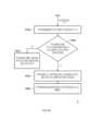
請參照圖1與圖2。首先,在步驟S202中,控制電路124通過SBU介面電路122向USB主機20提報第一配接器組態,以使USB主機20依據第一配接器組態列舉USB裝置10。在步驟S204中,在USB裝置10被列舉後,控制電路124觀察USB主機20對USB裝置10的行為。接著,在步驟S206中,控制電路124依據USB主機20的行為決定提報給USB主機20的所述第一配接器組態是否適用於USB主機20的連接管理器220。Please refer to Figure 1 and Figure 2. First, in step S202 , the
當第一配接器組態適用於連接管理器220時(步驟S206的判斷結果為「是」),控制電路124可以進行步驟S208。在步驟S208中,控制電路124判斷USB裝置10與USB主機20的連接管理器220具有相容性而不需有進一步的操作。當第一配接器組態不適用於連接管理器220時(步驟S206的判斷結果為「否」),控制電路124可以進行步驟S210。在步驟S210中,控制電路124改以第二配接器組態提報給USB主機20,以使USB主機20依據第二配接器組態重新列舉USB裝置10。When the first adapter configuration is applicable to the connection manager 220 (the determination result of step S206 is "Yes"), the
在一實施例中,第一配接器組態為配接器組態AC1,第二配接器組態為配接器組態AC2。在另一實施例中,第一配接器組態為配接器組態AC2,第二配接器組態為配接器組態AC1。其中,所述配接器組態AC1忠實表示USB積體電路120的多個配接器(例如圖1所示126a、126b、126c與126d),而所述配接器組態AC2包括一個(或多個)偽通道配接器。偽通道配接器(例如偽PCIe配接器等)是在USB積體電路120中實際上沒有的通道配接器。配接器組態AC2可以依照實際應用來決定其內容。舉例來說,配接器組態AC1例如包括2個USB4通道配接器、1個USB3上行(USB3 upstream)配接器及1個DP輸出配接器,而配接器組態AC2例如包括8個USB4通道配接器、1個不支援(Un-Supported)配接器、1個PCIe上行(PCIe upstream)配接器、3個PCIe下行(PCIe downstream)配接器、1個USB3上行配接器、3個USB3下行(USB3 downstream)配接器及2個DP輸出配接器。In one embodiment, the first adapter configuration is adapter configuration AC1, and the second adapter configuration is adapter configuration AC2. In another embodiment, the first adapter configuration is adapter configuration AC2, and the second adapter configuration is adapter configuration AC1. Wherein, the adapter configuration AC1 faithfully represents multiple adapters (such as 126a, 126b, 126c and 126d shown in FIG. 1 ) of the USB integrated
圖3A至圖3C為依照本發明另一實施例所繪示的USB積體電路的操作方法的流程示意圖。圖3A至圖3C所示操作方法3適用於圖1所示USB裝置10中的USB積體電路120。以下將參照圖1實施例的各項元件來詳細說明圖3A至圖3C所示操作方法3。3A to 3C are schematic flowcharts of an operation method of a USB integrated circuit according to another embodiment of the present invention. The
請參照圖1與圖3A至圖3C。首先,在步驟S302中,USB積體電路120執行上電操作。在步驟S304中,在USB積體電路120上電後,控制電路124判斷記憶體(圖1中未繪示)中是否儲存連接管理器220的有效資訊。在一實施例中,連接管理器220的有效資訊包括連接管理器220的版本或適用於連接管理器220的配接器組態,但本發明並不以此為限。Please refer to FIG. 1 and FIG. 3A to FIG. 3C . First, in step S302, the USB integrated
若控制電路124判斷記憶體中儲存連接管理器220的有效資訊(步驟S304的判斷結果為「是」),則控制電路124可以進行步驟S306。在步驟S306中,控制電路124依據有效資訊來配置初始配接器組態,並且向USB主機20提報初始配接器組態以使USB主機20列舉USB裝置10。具體來說,所述初始配接器組態可以是配接器組態AC1(忠實表示USB積體電路120的多個配接器的配接器組態),也可以是配接器組態AC2(包括一個或多個偽通道配接器的配接器組態)。控制電路124依據連接管理器220的版本或適用於連接管理器220的配接器組態通過SBU介面電路122向USB主機20提報相對應的初始配接器組態以使USB主機20列舉USB裝置10。If the
若控制電路124判斷記憶體中未儲存連接管理器220的有效資訊時(步驟S304的判斷結果為「否」),則控制電路124可以進行步驟S308。在步驟S308中,控制電路124以預設配接器組態作為目前使用的配接器組態(第一配接器組態),並且向USB主機20提報預設配接器組態以使USB主機20列舉USB裝置10。在一實施例中,所述預設配接器組態可以是配接器組態AC1(忠實表示USB積體電路120的多個配接器的配接器組態)。在另一實施例中,所述預設配接器組態可以是配接器組態AC2(包括一個或多個偽通道配接器的配接器組態)。詳細來說,控制電路124通過SBU介面電路122向USB主機20提報預設配接器組態(配接器組態AC1或配接器組態AC2)以使USB主機20列舉USB裝置10。If the
在步驟S310中,控制電路124通過SBU介面電路122發出讀取命令至USB主機20以取得USB主機20的VID和/或PID。接著,控制電路124依據USB主機20的VID和/或PID來決定是否續用預設配接器組態作為目前使用的配接器組態。具體地,在步驟S312中,控制電路124依據USB主機20的VID和/或PID來判斷USB主機20是否為某一廠商的USB連接管理器。在圖3A所示應用情境例中,所述某一廠商的連接管理器存在版本相容性問題。In step S310 , the
若控制電路124判斷USB主機20的連接管理器220非為所述某一廠商的USB連接管理器(步驟S312的判斷結果為「否」),則控制電路124可以進行步驟S314。在步驟S314中,控制電路124判斷USB裝置10與USB主機20的連接管理器220具有相容性(步驟S308所提報的所述預設配接器組態適用於連接管理器220)而不需有進一步的操作。If the
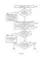
若控制電路124判斷USB主機20的連接管理器220為所述某一廠商的USB連接管理器(步驟S312的判斷結果為「是」),則控制電路124可以進行步驟S316。在步驟S316中,控制電路124判斷步驟S308所提報的所述預設配接器組態為配接器組態AC1(忠實表示USB積體電路120的多個配接器的配接器組態)還是配接器組態AC2(包括一個或多個偽通道配接器的配接器組態)。If the
若控制電路124判斷步驟S308所提報的所述預設配接器組態為配接器組態AC1(步驟S316的判斷結果為「配接器組態AC1」),則控制電路124可以進行圖3B所示步驟S318a。在步驟S318a中,控制電路124在USB裝置10被列舉後,觀察USB主機20對USB裝置10的行為。接著,在步驟S320a中,控制電路124依據USB主機20的行為判斷/決定配接器組態AC1是否適用於USB主機20的連接管理器220。具體來說,在一實施例中,控制電路124在以配接器組態AC1作為目前使用的配接器組態的情況下,當控制電路124所觀察到USB主機20的行為表示「在USB主機20與USB裝置10之間未建立USB3穿隧路徑(tunneling path)」時,控制電路124決定/判斷配接器組態AC1不適用於連接管理器220(步驟S320a的判斷結果為「否」)。反之,控制電路124決定/判斷配接器組態AC1適用於連接管理器220。If the
當配接器組態AC1適用於連接管理器220時(步驟S320a的判斷結果為「是」),則控制電路124可以進行步驟S322a。在步驟S322a中,控制電路124判斷USB裝置10與USB主機20的連接管理器220具有相容性而不需有進一步的操作。When the adapter configuration AC1 is applicable to the connection manager 220 (the determination result of step S320a is "Yes"), the
當配接器組態AC1不適用於連接管理器220時(步驟S320a的判斷結果為「否」),則控制電路124可以進行步驟S324a。在步驟S324a中,控制電路124改以配接器組態AC2(第二配接器組態)作為目前使用的配接器組態。亦即,控制電路124改以配接器組態AC2提報給USB主機20以使USB主機20重新列舉USB裝置10。在一實施例中,藉由重新建立USB連接器100的SBU接腳104與USB連接器200的SBU接腳204之間的SB通道,控制電路124可以使USB主機20重新列舉USB裝置10,此使得連接管理器220成功地在USB主機20與USB裝置10之間建立USB3穿隧路徑。When the adapter configuration AC1 is not applicable to the connection manager 220 (the determination result of step S320a is "No"), the
在步驟S326a中,在USB主機20重新列舉USB裝置10後,連接管理器220在USB主機20與USB裝置10之間建立具有第一標識碼的USB3穿隧路徑,以及控制電路124將連接管理器220所對應的有效資訊儲存至記憶體(未繪示)中。特別地,所述第一標識碼為傳輸在USB3穿隧路徑上的封包所記錄的HopID值,且在本實施例中,HopID值為0X10。在一實施例中,所述有效資訊包括連接管理器220的版本(例如NVM FW版本V34)或適用於連接管理器220的配接器組態AC2。在另一實施例中,有效資訊還包括所述第一標識碼,本實施例並不以此為限。In step S326a, after the
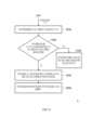
回到圖3A所示步驟S316,若控制電路124判斷步驟S308所提報的所述預設配接器組態為配接器組態AC2(步驟S316的判斷結果為「配接器組態AC2」),則控制電路124可以進行圖3C所示步驟S318b。在步驟S318b中,控制電路124在USB裝置10被列舉後,觀察USB主機20對USB裝置10的行為。接著,在步驟S320b中,控制電路124依據USB主機20的行為判斷/決定配接器組態AC2是否適用於USB主機20的連接管理器220。具體來說,若控制電路124在以配接器組態AC2作為目前使用的配接器組態的情況下,當控制電路124觀察到USB主機20的行為表示「在USB主機20與USB裝置10之間建立具有第二標識碼的USB3穿隧路徑」時,控制電路124決定配接器組態AC2不適用於連接管理器220(步驟S320b的判斷結果為「否」)。反之,控制電路124決定/判斷配接器組態AC2適用於連接管理器220。在一實施例中,所述第二標識碼為傳輸在USB3穿隧路徑上的封包所記錄的HopID值(在本實施例中,HopID值為0X08)。Returning to step S316 shown in FIG. 3A, if the
當配接器組態AC2適用於連接管理器220時(步驟S320b的判斷結果為「是」),則控制電路124可以進行步驟S322b。在步驟S322b中,控制電路124判斷USB裝置10與USB主機20的連接管理器220具有相容性而不需有進一步的操作。When the adapter configuration AC2 is applicable to the connection manager 220 (the determination result of step S320b is "Yes"), the
當配接器組態AC2不適用於連接管理器220時(步驟S320b的判斷結果為「否」),則控制電路124可以進行步驟S324b。在步驟S324b中,控制電路124改以配接器組態AC1(第二配接器組態)作為目前使用的配接器組態。亦即,控制電路124改以以配接器組態AC1提報給USB主機20以使USB主機20重新列舉USB裝置10。在一實施例中,藉由重新建立USB連接器100的SBU接腳104與USB連接器200的SBU接腳204之間的SB通道,控制電路124可以使USB主機20重新列舉USB裝置10,此使得USB4裝置從睡眠模式恢復後,連接管理器220不會在USB3穿隧路徑中發出異常的重置(reset)。When the adapter configuration AC2 is not suitable for the connection manager 220 (the determination result of the step S320b is "No"), the
在步驟S326b中,在USB主機20重新列舉USB裝置10後,控制電路124將連接管理器220所對應的有效資訊儲存至記憶體(未繪示)中。在一實施例中,所述有效資訊包括連接管理器220的版本(例如NVM FW版本V41)或適用於連接管理器220的配接器組態AC1。在另一實施例中,有效資訊還包括所述第二標識碼,本實施例並不以此為限。In step S326b, after the
值得注意的是,在本發明實施例的方法中步驟的特定順序及/或層次僅是示例性途徑。基於設計偏好,所公開的方法或過程的步驟的特定順序或層次可在保持在本發明實施例的範圍內的同時被重新佈置。因此,所屬領域中的一般技術人員將理解,本發明實施例的方法及技術以樣本順序呈現各種步驟或動作,且本發明實施例不限於所呈現的特定順序或層次,除非另有明確說明。It should be noted that the specific order and/or hierarchy of steps in the methods of the embodiments of the present invention is only an exemplary approach. Based upon design preferences, the specific order or hierarchy of steps in the disclosed methods or processes may be rearranged while remaining within the scope of the embodiments of the invention. Accordingly, those of ordinary skill in the art will understand that the methods and techniques of the present embodiments present various steps or actions in a sample order, and that the present embodiments are not limited to the specific order or hierarchy presented unless explicitly stated otherwise.
依照不同的設計需求,上述SBU介面電路122以及(或是)控制電路124的方塊的實現方式可以是硬體(hardware)、韌體(firmware)、軟體(software,即程式)或是前述三者中的多者的組合形式。According to different design requirements, the block implementation of the
以硬體形式而言,上述SBU介面電路122以及(或是)控制電路124的方塊可以實現於積體電路(integrated circuit)上的邏輯電路。上述SBU介面電路122以及(或是)控制電路124的相關功能可以利用硬體描述語言(hardware description languages,例如Verilog HDL或VHDL)或其他合適的編程語言來實現為硬體。舉例來說,上述SBU介面電路122以及(或是)控制電路124的相關功能可以被實現於一或多個控制器、微控制器、微處理器、特殊應用積體電路(Application-specific integrated circuit, ASIC)、數位訊號處理器(digital signal processor, DSP)、場可程式邏輯閘陣列(Field Programmable Gate Array, FPGA)及/或其他處理單元中的各種邏輯區塊、模組和電路。In terms of hardware, the blocks of the above-mentioned
以軟體形式及/或韌體形式而言,上述SBU介面電路122以及(或是)控制電路124的相關功能可以被實現為編程碼(programming codes)。例如,利用一般的編程語言(programming languages,例如C、C++或組合語言)或其他合適的編程語言來實現上述SBU介面電路122以及(或是)控制電路124。所述編程碼可以被記錄/存放在記錄媒體中,所述記錄媒體中例如包括唯讀記憶體(Read Only Memory,ROM)、存儲裝置及/或隨機存取記憶體(Random Access Memory,RAM)。電腦、中央處理器(Central Processing Unit,CPU)、控制器、微控制器或微處理器可以從所述記錄媒體中讀取並執行所述編程碼,從而達成相關功能。作為所述記錄媒體,可使用「非臨時的電腦可讀取媒體(non-transitory computer readable medium)」,例如可使用帶(tape)、碟(disk)、卡(card)、半導體記憶體、可程式設計的邏輯電路等。而且,所述程式也可經由任意傳輸媒體(通信網路或廣播電波等)而提供給所述電腦(或CPU)。所述通信網路例如是互聯網(Internet)、有線通信(wired communication)、無線通信(wireless communication)或其它通信介質。In terms of software and/or firmware, the related functions of the above-mentioned
綜上所述,上述諸實施例所提供的USB積體電路、USB積體電路的操作方法及USB裝置,能夠向USB主機提報預設配接器組態,然後在USB主機列舉USB裝置後觀察USB主機對USB裝置的行為來判斷連接管理器的版本以及預設配接器組態是否適用於USB主機的連接管理器。在預設配接器組態不適用於連接管理器時,USB積體電路可以改向USB主機提報另一配接器組態以使USB主機重新列舉USB裝置。如此一來,USB裝置可依據連接管理器的版本向USB主機提報相對應的配接器組態,因而可與任意版本的連接管理器具有相容性。To sum up, the USB integrated circuit, the operation method of the USB integrated circuit, and the USB device provided by the above-mentioned embodiments can report the default adapter configuration to the USB host, and then after the USB host enumerates the USB device, Observe the behavior of the USB host to the USB device to determine whether the version of the connection manager and the default adapter configuration are suitable for the connection manager of the USB host. When the default adapter configuration is not applicable to the connection manager, the USB IC can instead report another adapter configuration to the USB host so that the USB host can re-enumerate the USB device. In this way, the USB device can report the corresponding adapter configuration to the USB host according to the version of the connection manager, so it can be compatible with any version of the connection manager.
雖然本發明已以實施例揭露如上,然其並非用以限定本發明,任何所屬技術領域中具有通常知識者,在不脫離本發明的精神和範圍內,當可作些許的更動與潤飾,故本發明的保護範圍當視後附的申請專利範圍所界定者為準。Although the present invention has been disclosed above with the embodiments, it is not intended to limit the present invention. Anyone with ordinary knowledge in the technical field may make some changes and modifications without departing from the spirit and scope of the present invention. The scope of protection of the present invention should be defined by the scope of the appended patent application.
1: USB傳輸系統 2、3: 操作方法 10: USB裝置 20: USB主機 100、200: USB連接器 102、202: 通道接腳 104、204: 邊帶使用(SBU)接腳 120: USB積體電路 122: SBU介面電路 124: 控制電路 126a、126b、126c、126d、226a、226b、226c、226d: 通道配接器 128、228: USB傳輸層電路 220: 連接管理器 AC1、AC2: 配接器組態 S202、S204、S206、S208、S210、S302、S304、S306、S308、S310、S312、S314、S316、S318a、S318b、S320a、S320b、S322a、S322b、S324a、S324b、S326a、S326b:步驟1:
圖1為依照本發明一實施例所繪示的USB傳輸系統的電路方塊(circuit block)示意圖。 圖2為依照本發明一實施例所繪示的USB積體電路的操作方法的流程示意圖。 圖3A至圖3C為依照本發明另一實施例所繪示的USB積體電路的操作方法的流程示意圖。FIG. 1 is a schematic diagram of a circuit block of a USB transmission system according to an embodiment of the present invention. FIG. 2 is a schematic flowchart of an operation method of a USB integrated circuit according to an embodiment of the present invention. 3A to 3C are schematic flowcharts of an operation method of a USB integrated circuit according to another embodiment of the present invention.
1: USB傳輸系統 10: USB裝置 20: USB主機 100、200: USB連接器 102、202: 通道接腳 104、204: 邊帶使用(SBU)接腳 120: USB積體電路 122: SBU介面電路 124: 控制電路 126a、126b、126c、126d、226a、226b、226c、226d: 通道配接器 128、228: USB傳輸層電路 220: 連接管理器1: USB transfer system 10: USB device 20:
Claims (20)
Translated fromChinesePriority Applications (2)
| Application Number | Priority Date | Filing Date | Title |
|---|---|---|---|
| CN202211126553.2ACN115391242B (en) | 2021-12-01 | 2022-09-16 | USB integrated circuit, USB integrated circuit operating method, and USB device |
| US17/990,739US12197366B2 (en) | 2021-12-01 | 2022-11-21 | USB integrated circuit, operation method of USB integrated circuit and USB device |
Applications Claiming Priority (2)
| Application Number | Priority Date | Filing Date | Title |
|---|---|---|---|
| US202163284642P | 2021-12-01 | 2021-12-01 | |
| US63/284,642 | 2021-12-01 |
Publications (2)
| Publication Number | Publication Date |
|---|---|
| TW202324124A TW202324124A (en) | 2023-06-16 |
| TWI810032Btrue TWI810032B (en) | 2023-07-21 |
Family
ID=87803585
Family Applications (1)
| Application Number | Title | Priority Date | Filing Date |
|---|---|---|---|
| TW111131560ATWI810032B (en) | 2021-12-01 | 2022-08-22 | Usb integrated circuit, operation method of usb integrated circuit and usb device |
Country Status (1)
| Country | Link |
|---|---|
| TW (1) | TWI810032B (en) |
Families Citing this family (1)
| Publication number | Priority date | Publication date | Assignee | Title |
|---|---|---|---|---|
| TWI873044B (en)* | 2024-05-27 | 2025-02-11 | 祥碩科技股份有限公司 | Usb circuit and operating method thereof and usb device |
Citations (5)
| Publication number | Priority date | Publication date | Assignee | Title |
|---|---|---|---|---|
| TW201706772A (en)* | 2015-04-28 | 2017-02-16 | 微晶片科技公司 | Universal serial bus smart hub |
| CN107085507A (en)* | 2016-02-16 | 2017-08-22 | 三星电子株式会社 | Data sending and receiving method and device |
| US20180267918A1 (en)* | 2017-03-16 | 2018-09-20 | Wyse Technology L.L.C. | Virtualizing a non-usb device as a usb device |
| US20180356873A1 (en)* | 2017-06-13 | 2018-12-13 | Intel Corporation | Method to enhance device policy management (dpm) power sharing for usb type-c (usb-c) only devices |
| TW201913402A (en)* | 2017-09-08 | 2019-04-01 | 瑞昱半導體股份有限公司 | Docking device, electronic device and method for setting basic input/output system |
- 2022
- 2022-08-22TWTW111131560Apatent/TWI810032B/enactive
Patent Citations (5)
| Publication number | Priority date | Publication date | Assignee | Title |
|---|---|---|---|---|
| TW201706772A (en)* | 2015-04-28 | 2017-02-16 | 微晶片科技公司 | Universal serial bus smart hub |
| CN107085507A (en)* | 2016-02-16 | 2017-08-22 | 三星电子株式会社 | Data sending and receiving method and device |
| US20180267918A1 (en)* | 2017-03-16 | 2018-09-20 | Wyse Technology L.L.C. | Virtualizing a non-usb device as a usb device |
| US20180356873A1 (en)* | 2017-06-13 | 2018-12-13 | Intel Corporation | Method to enhance device policy management (dpm) power sharing for usb type-c (usb-c) only devices |
| TW201913402A (en)* | 2017-09-08 | 2019-04-01 | 瑞昱半導體股份有限公司 | Docking device, electronic device and method for setting basic input/output system |
Also Published As
| Publication number | Publication date |
|---|---|
| TW202324124A (en) | 2023-06-16 |
Similar Documents
| Publication | Publication Date | Title |
|---|---|---|
| TWI416409B (en) | A method for booting a host device from an mmc/sd device, a host device bootable from an mmc/sd device and an mmc/sd device a host device may be booted from | |
| US10114658B2 (en) | Concurrent testing of PCI express devices on a server platform | |
| US9542201B2 (en) | Network bios management | |
| US9529410B2 (en) | Service processor (SP) initiated data transaction with BIOS utilizing power off commands | |
| TWI760615B (en) | Method for performing detect control of write protection command of memory device, associated control chip and associated electronic device | |
| US9806959B2 (en) | Baseboard management controller (BMC) to host communication through device independent universal serial bus (USB) interface | |
| US9779047B2 (en) | Universal intelligent platform management interface (IPMI) host to baseboard management controller (BMC) communication for non-x86 and legacy free systems | |
| US10656676B2 (en) | Docking device, electrical device, and MAC address cloning method | |
| KR20180085192A (en) | System including hot plug module and memory module | |
| JP2018116648A (en) | Information processing apparatus, control method thereof, and program | |
| TWI810032B (en) | Usb integrated circuit, operation method of usb integrated circuit and usb device | |
| CN116150064A (en) | Hot plug method of NVME storage device, backboard and computing device | |
| CN118672367A (en) | Computer system, bandwidth configuration method, product, server and medium | |
| CN114356411A (en) | A hard disk power-on and power-off control system applied to an Ampere server | |
| CN100437489C (en) | Method for saving system resource | |
| CN118626428A (en) | Bandwidth allocation method, server, device, medium and program product | |
| CN115391242B (en) | USB integrated circuit, USB integrated circuit operating method, and USB device | |
| CN118484421A (en) | System log processing method, device, electronic device and storage medium | |
| CN118132458A (en) | MMIO address resource allocation method, device, computing device and storage medium | |
| CN117349212A (en) | Server main board and solid state disk insertion detection method thereof | |
| CN116540933A (en) | Data read-write method and device for charging chip | |
| CN116701005A (en) | Port management method based on connector and related equipment | |
| CN102760064A (en) | Network card updating device and method | |
| CN114297120A (en) | A kind of bandwidth allocation method, device and system | |
| CN114003535A (en) | Equipment bandwidth configuration method and system, electronic equipment and storage medium |