TWI807964B - Method for manufacturing liquid container and glass article - Google Patents
Method for manufacturing liquid container and glass articleDownload PDFInfo
- Publication number
- TWI807964B TWI807964BTW111130747ATW111130747ATWI807964BTW I807964 BTWI807964 BTW I807964BTW 111130747 ATW111130747 ATW 111130747ATW 111130747 ATW111130747 ATW 111130747ATW I807964 BTWI807964 BTW I807964B
- Authority
- TW
- Taiwan
- Prior art keywords
- fitting
- liquid container
- liquid
- narrow
- narrow portion
- Prior art date
Links
Images


Classifications
- B—PERFORMING OPERATIONS; TRANSPORTING
- B65—CONVEYING; PACKING; STORING; HANDLING THIN OR FILAMENTARY MATERIAL
- B65D—CONTAINERS FOR STORAGE OR TRANSPORT OF ARTICLES OR MATERIALS, e.g. BAGS, BARRELS, BOTTLES, BOXES, CANS, CARTONS, CRATES, DRUMS, JARS, TANKS, HOPPERS, FORWARDING CONTAINERS; ACCESSORIES, CLOSURES, OR FITTINGS THEREFOR; PACKAGING ELEMENTS; PACKAGES
- B65D90/00—Component parts, details or accessories for large containers
- B65D90/02—Wall construction
- B65D90/08—Interconnections of wall parts; Sealing means therefor
- B—PERFORMING OPERATIONS; TRANSPORTING
- B65—CONVEYING; PACKING; STORING; HANDLING THIN OR FILAMENTARY MATERIAL
- B65D—CONTAINERS FOR STORAGE OR TRANSPORT OF ARTICLES OR MATERIALS, e.g. BAGS, BARRELS, BOTTLES, BOXES, CANS, CARTONS, CRATES, DRUMS, JARS, TANKS, HOPPERS, FORWARDING CONTAINERS; ACCESSORIES, CLOSURES, OR FITTINGS THEREFOR; PACKAGING ELEMENTS; PACKAGES
- B65D7/00—Containers having bodies formed by interconnecting or uniting two or more rigid, or substantially rigid, components made wholly or mainly of metal
- B65D7/12—Containers having bodies formed by interconnecting or uniting two or more rigid, or substantially rigid, components made wholly or mainly of metal characterised by wall construction or by connections between walls
- B65D7/24—Containers having bodies formed by interconnecting or uniting two or more rigid, or substantially rigid, components made wholly or mainly of metal characterised by wall construction or by connections between walls collapsible, e.g. with all parts detachable
- C—CHEMISTRY; METALLURGY
- C03—GLASS; MINERAL OR SLAG WOOL
- C03B—MANUFACTURE, SHAPING, OR SUPPLEMENTARY PROCESSES
- C03B5/00—Melting in furnaces; Furnaces so far as specially adapted for glass manufacture
- C03B5/16—Special features of the melting process; Auxiliary means specially adapted for glass-melting furnaces
- C03B5/42—Details of construction of furnace walls, e.g. to prevent corrosion; Use of materials for furnace walls
- B—PERFORMING OPERATIONS; TRANSPORTING
- B41—PRINTING; LINING MACHINES; TYPEWRITERS; STAMPS
- B41B—MACHINES OR ACCESSORIES FOR MAKING, SETTING, OR DISTRIBUTING TYPE; TYPE; PHOTOGRAPHIC OR PHOTOELECTRIC COMPOSING DEVICES
- B41B11/00—Details of, or accessories for, machines for mechanical composition using matrices for individual characters which are selected and assembled for type casting or moulding
- B41B11/52—Moulding or casting devices or associated mechanisms
- B41B11/54—Moulds; Liners therefor
- B—PERFORMING OPERATIONS; TRANSPORTING
- B65—CONVEYING; PACKING; STORING; HANDLING THIN OR FILAMENTARY MATERIAL
- B65D—CONTAINERS FOR STORAGE OR TRANSPORT OF ARTICLES OR MATERIALS, e.g. BAGS, BARRELS, BOTTLES, BOXES, CANS, CARTONS, CRATES, DRUMS, JARS, TANKS, HOPPERS, FORWARDING CONTAINERS; ACCESSORIES, CLOSURES, OR FITTINGS THEREFOR; PACKAGING ELEMENTS; PACKAGES
- B65D7/00—Containers having bodies formed by interconnecting or uniting two or more rigid, or substantially rigid, components made wholly or mainly of metal
- B65D7/02—Containers having bodies formed by interconnecting or uniting two or more rigid, or substantially rigid, components made wholly or mainly of metal characterised by shape
- B65D7/04—Containers having bodies formed by interconnecting or uniting two or more rigid, or substantially rigid, components made wholly or mainly of metal characterised by shape of curved cross-section, e.g. cans of circular or elliptical cross-section
- B—PERFORMING OPERATIONS; TRANSPORTING
- B65—CONVEYING; PACKING; STORING; HANDLING THIN OR FILAMENTARY MATERIAL
- B65D—CONTAINERS FOR STORAGE OR TRANSPORT OF ARTICLES OR MATERIALS, e.g. BAGS, BARRELS, BOTTLES, BOXES, CANS, CARTONS, CRATES, DRUMS, JARS, TANKS, HOPPERS, FORWARDING CONTAINERS; ACCESSORIES, CLOSURES, OR FITTINGS THEREFOR; PACKAGING ELEMENTS; PACKAGES
- B65D7/00—Containers having bodies formed by interconnecting or uniting two or more rigid, or substantially rigid, components made wholly or mainly of metal
- B65D7/02—Containers having bodies formed by interconnecting or uniting two or more rigid, or substantially rigid, components made wholly or mainly of metal characterised by shape
- B65D7/06—Containers having bodies formed by interconnecting or uniting two or more rigid, or substantially rigid, components made wholly or mainly of metal characterised by shape of polygonal cross-section, e.g. tins, boxes
- B—PERFORMING OPERATIONS; TRANSPORTING
- B65—CONVEYING; PACKING; STORING; HANDLING THIN OR FILAMENTARY MATERIAL
- B65D—CONTAINERS FOR STORAGE OR TRANSPORT OF ARTICLES OR MATERIALS, e.g. BAGS, BARRELS, BOTTLES, BOXES, CANS, CARTONS, CRATES, DRUMS, JARS, TANKS, HOPPERS, FORWARDING CONTAINERS; ACCESSORIES, CLOSURES, OR FITTINGS THEREFOR; PACKAGING ELEMENTS; PACKAGES
- B65D7/00—Containers having bodies formed by interconnecting or uniting two or more rigid, or substantially rigid, components made wholly or mainly of metal
- B65D7/12—Containers having bodies formed by interconnecting or uniting two or more rigid, or substantially rigid, components made wholly or mainly of metal characterised by wall construction or by connections between walls
- B65D7/22—Containers having bodies formed by interconnecting or uniting two or more rigid, or substantially rigid, components made wholly or mainly of metal characterised by wall construction or by connections between walls with double walls, e.g. double end walls
- B—PERFORMING OPERATIONS; TRANSPORTING
- B65—CONVEYING; PACKING; STORING; HANDLING THIN OR FILAMENTARY MATERIAL
- B65D—CONTAINERS FOR STORAGE OR TRANSPORT OF ARTICLES OR MATERIALS, e.g. BAGS, BARRELS, BOTTLES, BOXES, CANS, CARTONS, CRATES, DRUMS, JARS, TANKS, HOPPERS, FORWARDING CONTAINERS; ACCESSORIES, CLOSURES, OR FITTINGS THEREFOR; PACKAGING ELEMENTS; PACKAGES
- B65D90/00—Component parts, details or accessories for large containers
- B65D90/02—Wall construction
- B65D90/028—Wall construction hollow-walled, e.g. double-walled with spacers
- C—CHEMISTRY; METALLURGY
- C03—GLASS; MINERAL OR SLAG WOOL
- C03B—MANUFACTURE, SHAPING, OR SUPPLEMENTARY PROCESSES
- C03B18/00—Shaping glass in contact with the surface of a liquid
- C03B18/02—Forming sheets
- C03B18/16—Construction of the float tank; Use of material for the float tank; Coating or protection of the tank wall
- C—CHEMISTRY; METALLURGY
- C03—GLASS; MINERAL OR SLAG WOOL
- C03B—MANUFACTURE, SHAPING, OR SUPPLEMENTARY PROCESSES
- C03B19/00—Other methods of shaping glass
- C03B19/02—Other methods of shaping glass by casting molten glass, e.g. injection moulding
- B—PERFORMING OPERATIONS; TRANSPORTING
- B41—PRINTING; LINING MACHINES; TYPEWRITERS; STAMPS
- B41B—MACHINES OR ACCESSORIES FOR MAKING, SETTING, OR DISTRIBUTING TYPE; TYPE; PHOTOGRAPHIC OR PHOTOELECTRIC COMPOSING DEVICES
- B41B11/00—Details of, or accessories for, machines for mechanical composition using matrices for individual characters which are selected and assembled for type casting or moulding
- B41B11/52—Moulding or casting devices or associated mechanisms
- B41B11/74—Devices for supplying molten metal
- B—PERFORMING OPERATIONS; TRANSPORTING
- B65—CONVEYING; PACKING; STORING; HANDLING THIN OR FILAMENTARY MATERIAL
- B65D—CONTAINERS FOR STORAGE OR TRANSPORT OF ARTICLES OR MATERIALS, e.g. BAGS, BARRELS, BOTTLES, BOXES, CANS, CARTONS, CRATES, DRUMS, JARS, TANKS, HOPPERS, FORWARDING CONTAINERS; ACCESSORIES, CLOSURES, OR FITTINGS THEREFOR; PACKAGING ELEMENTS; PACKAGES
- B65D90/00—Component parts, details or accessories for large containers
- B65D90/02—Wall construction
- B65D90/04—Linings
Landscapes
- Engineering & Computer Science (AREA)
- Mechanical Engineering (AREA)
- Chemical & Material Sciences (AREA)
- Materials Engineering (AREA)
- Organic Chemistry (AREA)
- Manufacturing & Machinery (AREA)
- Details Of Rigid Or Semi-Rigid Containers (AREA)
- Rigid Containers With Two Or More Constituent Elements (AREA)
- Ink Jet (AREA)
- Table Devices Or Equipment (AREA)
- Thermally Insulated Containers For Foods (AREA)
- Devices For Use In Laboratory Experiments (AREA)
- Glass Compositions (AREA)
- Containers And Packaging Bodies Having A Special Means To Remove Contents (AREA)
- Re-Forming, After-Treatment, Cutting And Transporting Of Glass Products (AREA)
Abstract
Translated fromChineseDescription
Translated fromChinese發明領域 本發明是有關於一種收納液體的容器(亦稱為液體容器)及其利用。field of invention The present invention relates to a container for accommodating liquid (also called a liquid container) and its utilization.
發明背景 作為可再利用的組立式的小型的液體容器,已知有在外筒的內側收納內筒,且將內筒的下端部與底部對接,而外筒的下端部與底部的外周嵌合的容器(專利文獻1)。已有下述作法被提出:此液體容器是藉由設成組立式,而可例如即便在將其作為飲食用液體等的容器來使用後也不會形成用過即丟的情形,而可在將容器分割為外筒、內筒、底部,且將各構成構件洗淨後組裝再利用。 另一方面,特別是在將大型的液體容器形成為組立式的情況下,需要組合大量的構件。因此,在大型液體容器中,會要求防止液體從組合成的構件之間的間隙流出或漏出之特別的工夫,且要形成為組立式是困難的。 先前技術文獻 專利文獻Background of the invention As a small reusable vertical liquid container, there is known a container in which an inner cylinder is housed inside an outer cylinder, the lower end of the inner cylinder is butted against the bottom, and the lower end of the outer cylinder is fitted to the outer periphery of the bottom (Patent Document 1). The following method has been proposed: the liquid container can be assembled and reused after being divided into an outer cylinder, an inner cylinder, and a bottom, and each constituent member can be assembled and reused after being used as a container for a liquid for eating or drinking, for example, by setting the liquid container in a vertical form. On the other hand, especially when forming a large liquid container into a vertical type, it is necessary to combine a large number of components. Therefore, in a large liquid container, special work is required to prevent the liquid from flowing out or leaking from the gap between the assembled members, and it is difficult to form it in a vertical form. prior art literature patent documents
專利文獻1:日本專利特開2010-215239號公報Patent Document 1: Japanese Patent Laid-Open No. 2010-215239
發明概要 發明欲解決之課題 本發明是提供一種不會有收納的液體的流出或漏出,且可以用組立式的方式形成的大型的液體容器。又,本發明是提供一種該液體容器的有效的使用、即玻璃物品的製造方法。 用以解決課題之手段Summary of the invention The problem to be solved by the invention The present invention provides a large-scale liquid container which can be formed vertically without the outflow or leakage of the stored liquid. Moreover, this invention provides the efficient use of this liquid container, ie, the manufacturing method of a glass article. means to solve problems
本發明具有以下之態樣。 [1]一種液體容器,是收納液體的液體容器,至少由第1構件、第2構件、及第3構件所形成,且具備第1嵌合部及第2嵌合部、以及第3嵌合部,前述第1嵌合部及第2嵌合部是藉由前述第1構件及前述第2構件對接並嵌合而形成,前述第3嵌合部是藉由前述第3構件朝交叉於前述第1構件及前述第2構件的嵌合方向的方向與前述第1構件及前述第2構件對接並嵌合而形成。 [2]如[1]之液體容器,其中前述第1嵌合部具有第1狹小部,前述第1狹小部在前述第1構件及前述第2構件的嵌合方向上、且從沿著前述液體容器的內表面的方向觀看為交叉的方向上形成間隙,前述第2嵌合部具有第2狹小部,前述第2狹小部在前述第1構件及前述第2構件的嵌合方向上、且沿著前述液體容器的內表面的方向上形成間隙,前述第3嵌合部具有第3狹小部,前述第3狹小部在交叉於前述第1構件及前述第2構件之嵌合方向的方向上、且從沿著前述液體容器的內表面的方向觀看為交叉的方向上形成間隙,使前述第2狹小部介於前述第1狹小部與前述第3狹小部之間,且以前述第2狹小部使前述第1狹小部及前述第3狹小部連續,前述液體容器的底部及從前述底部的周邊往前述液體容器的深度方向延伸的壁部之內側,至少是由前述第3構件所形成。 [3]一種玻璃物品的製造方法,其特徵在於使用收納在前述液體容器中的熔融玻璃。 [4]一種玻璃物品的製造方法,其特徵在於藉由前述液體容器來收納熔融金屬,且讓熔融玻璃浮在該熔融金屬上來成形。 發明效果The present invention has the following aspects. [1] A liquid container for storing liquid, which is formed by at least a first member, a second member, and a third member, and has a first fitting portion, a second fitting portion, and a third fitting portion. The aforementioned second member is formed by butting and fitting. [2] The liquid container according to [1], wherein the first fitting portion has a first narrow portion, the first narrow portion forms a gap in the fitting direction of the first member and the second member, and a direction intersecting when viewed along the inner surface of the liquid container, the second fitting portion has a second narrow portion, and the second narrow portion forms a gap in the fitting direction of the first member and the second member and along the inner surface of the liquid container, and the third fitting portion There is a third narrow portion, the third narrow portion forms a gap in a direction intersecting the fitting direction of the first member and the second member, and in a direction intersecting when viewed from a direction along the inner surface of the liquid container, the second narrow portion is interposed between the first narrow portion and the third narrow portion, and the first narrow portion and the third narrow portion are continuous by the second narrow portion, between the bottom of the liquid container and the wall extending from the periphery of the bottom to the depth direction of the liquid container The inner side is formed by at least the aforementioned third member. [3] A method of manufacturing a glass article, characterized by using molten glass accommodated in the liquid container. [4] A method of manufacturing a glass article, comprising accommodating molten metal in the liquid container and forming molten glass by floating on the molten metal. Invention effect
根據本發明,可提供一種不會有收納的液體的流出或漏出,且可形成大型化之組立式的液體容器。又,根據本發明,可提供一種液體容器的有效的使用、即玻璃物品的製造方法。According to the present invention, it is possible to provide a vertical liquid container that does not prevent the liquid contained therein from flowing out or leaking, and that can be increased in size. Moreover, according to this invention, the efficient use of a liquid container, ie, the manufacturing method of a glass article can be provided.
用以實施發明之形態 根據圖式來說明本發明的實施形態。再者,本發明並不限定於以下的實施之形態,且可在本發明的技術思想的範圍內任意地變更。又,在以下的圖式中,為了更容易地了解各構成,有使各構造中的比例及數量等與實際的構造中的比例及數量等不同來顯示的情況。form for carrying out the invention Embodiments of the present invention will be described based on the drawings. In addition, this invention is not limited to the form of embodiment below, It can change arbitrarily within the range of the technical thought of this invention. In addition, in the following drawings, in order to understand each structure more easily, the ratio, number, etc. in each structure may be displayed differently from the ratio, number, etc. in an actual structure.
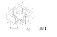
[第1實施形態] 如圖1、圖2所示,液體容器1是以形成為四邊形的底部10、與沿著底部10的外緣形成為方框的壁部15所形成。壁部15是在從底部10的外緣(周邊)朝液體容器1的深度方向立起的狀態下延伸。液體容器1是底部10的相反側形成開口。液體容器1是以底部10與壁部15來將液體L收納於內部I。 具體而言,液體容器1是藉由複數個第1構件11、第2構件12、與複數個第3構件13所組裝而成。第2構件12是設置於底部10的中央。複數個第1構件11是與第2構件12嵌合。複數個第3構件13是與第2構件12及第1構件11嵌合。於此,在第1構件11、第2構件12、第3構件13中,將主表面的周緣稱為端部。嵌合是在第1構件11、第2構件12、與第3構件13的端部彼此來進行。[First Embodiment] As shown in FIGS. 1 and 2 , the
如圖3所示,第1構件11具備有第1接合部1101與第2接合部1102。第1接合部1101是形成液體容器1的底部10(參照圖1)的一部分。第2接合部1102是從第1接合部1101的外端部1101a朝液體容器1的深度方向以交叉的方式延伸。第2接合部1102是形成壁部15(參照圖1)的一部分。As shown in FIG. 3 , the
如圖4、圖5所示,第1構件11是在兩側部具有第3凹部117。第1構件11的第1接合部1101是從液體容器1的壁部15(參照圖1)延伸到第2構件12。第1接合部1101是在液體容器1的中央側的端部(以下稱為內端部)1101b上具有第1嵌合突出部1110。第1嵌合突出部1110具有第1突出部111及第2凹部116。 第1突出部111具有一對第1突出面111a、111b。第2凹部116具有一對第1凹側面116a、116b。As shown in FIGS. 4 and 5 , the
如圖3所示,在液體容器1的底部15(參照圖1)的中央設置有第2構件12。第1接合部1101的第1嵌合突出部1110與第2構件12嵌合。第2構件12具有形成中央部的基座19、與形成在基座19的周圍的複數個第2嵌合凹部1210。 第2嵌合凹部1210是從基座19的外周朝向液體容器1的外部O在周方向上間隔等間隔而放射狀地突出。As shown in FIG. 3 , the
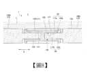
如圖5、圖6、與圖7所示,第2嵌合凹部1210具有與第1突出部111嵌合的第1凹部125、與形成於第1凹部125的一對第2突出部122。第1凹部125具有一對第1凹面125a、125b。第2突出部122具有一對突側面122a、122b。 可藉由使第1嵌合突出部1110的第1突出部111與第2嵌合凹部1210的第1凹部125嵌合,而形成第1嵌合部101。As shown in FIGS. 5 , 6 , and 7 , the
可藉由第1突出部111與第1凹部125嵌合,而以一對第1突出面111a、111b的一邊的第1突出面111a、與一對第1凹面125a、125b的一邊的第1凹面125a形成第1狹小部S1。可藉一對第1突出面111a、111b的另一邊的第1突出面111b、與一對第1凹面125a、125b的另一邊的第1凹面125b形成第1狹小部S2。 亦即,第1嵌合部101具有一對第1狹小部S1、S2。一對第1狹小部S1、S2是將間隙形成為抑制液體容器1內的液體L的流出的空間。換而言之,一對第1狹小部S1、S2的間隙是無法形成液體L的路徑的大小,且之後的狹小部也是同樣。By fitting the
一對第1狹小部S1、S2是在第1構件11及第2構件12的嵌合方向(箭頭A方向)上、且從沿著液體容器1的底面(內表面)10a的方向觀看為交叉的方向(亦即液體容器1的深度方向)上形成間隙。 一對第1狹小部S1、S2的各間隙不必為固定的間隔,只要比規定的值小即可,且亦可為間隙全部或一部分為零,亦可依位置而改變間隙。在後述的其他的狹小部的間隙上也是同樣。The pair of first narrow portions S1 and S2 form a gap in the fitting direction (arrow A direction) of the
第2凹部116具有一對第1凹側面116a、116b。第2突出部122具有一對突側面122a、122b。可藉由使第1嵌合突出部1110的第2凹部116與第2嵌合凹部1210的第2突出部122嵌合,而形成第2嵌合部102。 可藉由在第2凹部116嵌合第2突出部122,而以一對第1凹側面116a、116b的一邊的第1凹側面116a、與一對突側面122a、122b的一邊的突側面122a形成第2狹小部S3。以一對第1凹側面116a、116b的另一邊的第1凹側面116b、與一對突側面122a、122b的另一邊的突側面122b形成第2狹小部S4。 亦即,第2嵌合部102具有一對第2狹小部S3、S4。第2狹小部S3、S4是將間隙形成為抑制液體容器1內的液體L的流出的空間。第2狹小部S3、S4是在第1構件11及第2構件12的嵌合方向(箭頭A方向)上、且沿著液體容器1的底面(內表面)10a的方向上形成間隙。The second
回到圖2、圖3,可在第1突出部111與第1凹部125嵌合,且第2突出部122與第2凹部116(亦參照圖7)嵌合的狀態下,將第2構件12及第1構件11的第1接合部1101形成於液體容器1的底部10(參照圖1)的一部分。 藉由第2接合部1102在交叉於第1接合部1101的方向(亦即,深度方向)上延伸,可將第2接合部1102形成於液體容器1的壁部15(參照圖1)的一部分。 第3構件13的第3突出部133與第1構件11的第3凹部117及第2構件12的第3凹部127嵌合。 第3構件13具有第1平坦部1305與第2平坦部1306。此外,第3構件13具有與第1構件11的第3凹部117及第2構件12的第3凹部127嵌合的第3突出部133。Referring back to FIGS. 2 and 3 , in a state where the first protruding
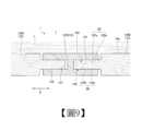
如圖8、圖9所示,第1構件11的第3凹部117具有一對第3凹面117a、117b。第3突出部133具有一對第3突出面133a、133b。 第3突出部133朝交叉於第1構件11及第2構件12的嵌合方向(箭頭A方向)的方向(箭頭B方向)與第1構件11的第1接合部1101嵌合。以第1接合部1101及第3突出部133形成第3嵌合部103。 又,第2構件12的第3凹部127具有一對第3凹面127a、127b。第3突出部133朝交叉於第1構件11及第2構件12的嵌合方向(箭頭A方向)的方向(箭頭B方向)與第2構件12的第3凹部127嵌合。 可如以第1接合部1101及第3突出部133形成第3嵌合部103的方式,來以第2構件12及第3突出部133形成第3嵌合部103。As shown in FIGS. 8 and 9 , the third
可藉由第3突出部133與第1構件11(第1接合部1101)的第3凹部117嵌合,而藉由第3突出部133的第3突出面133a與第3凹部117的第3凹面117a來形成第3狹小部S5。可藉由第3突出部133的第3突出面133b與第3凹部117的第3凹面117b來形成第3狹小部S6。 第3狹小部S5、S6是將間隙形成為抑制液體容器1內的液體L的流出的空間。第3狹小部S5、S6是在交叉於第1構件11及第2構件12的嵌合方向的方向、且從沿著液體容器1的底面10a的方向觀看為交叉的方向(液體容器1的深度方向)上形成間隙。The third narrow portion S5 can be formed by the third protruding
可藉由第3突出部133與第2構件12的第3凹部127嵌合,而藉由第3突出部133的第3突出面133a與第3凹部127的第3凹面127a,來與第3突出部133及第1構件11的第3狹小部S5同樣地形成第3狹小部S5。可藉由第3突出部133的第3突出面133b與第3凹部127的第3凹面127b,來與第3突出部133及第1構件11的第3狹小部S6同樣地形成第3狹小部S6。By fitting the
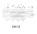
如圖7、圖10所示,在將第1構件11與第2構件12對接,且例如產生了由地震所造成的變形或施工誤差的情況下,會在第1突出部111的前端部111c與第1凹部125(參照圖6)的底部125c之間形成空間P1。 在第1實施形態中,空間P1並未與液體容器1的內部I連通。又,在將第3突出部133的前端部133c與第3凹部117的底部117c對接,且例如產生了由地震所造成的變形或施工誤差的情況下,會形成空間P2。在第1實施形態中,空間P2並未與液體容器1的外部O連通。這是由於第1實施形態下了不使流入空間P1的液體L流入空間P2之工夫的緣故。As shown in FIGS. 7 and 10 , when the
亦即,在第1實施形態中,是在空間P1與空間P2之間形成第2狹小部S3,而使第2狹小部S3介於第1狹小部S1與第3狹小部S5之間,且藉由第2狹小部S3使第1狹小部S1與第3狹小部S5連續。 在與第1實施形態有所不同,嵌合部為一個的情況下,於嵌合偏離而產生有空間時,該空間會成為液體的路徑。而且,因為對於嵌合方向以外的方向的移位,並沒有構件間的變形的自由度,因而導致形成液體的路徑。 在與第1實施形態有所不同,嵌合部為二個的情況下,於嵌合偏離而產生有空間時,雖然一部分的空間並不會成為液體的路徑,但其他空間會成為液體的路徑。而且,因為對於嵌合方向以外的方向的移位,並沒有構件間的變形的自由度,因而導致形成液體的路徑。That is, in the first embodiment, the second narrow portion S3 is formed between the space P1 and the space P2 so that the second narrow portion S3 is interposed between the first narrow portion S1 and the third narrow portion S5, and the first narrow portion S1 and the third narrow portion S5 are continuous through the second narrow portion S3. Unlike the first embodiment, in the case where there is one fitting portion, when a space is created due to fitting deviation, the space becomes a path for the liquid. Furthermore, since there is no degree of freedom of deformation between members for displacement in a direction other than the fitting direction, a liquid path is formed. Unlike the first embodiment, when there are two fitting parts, when there is a space due to fitting deviation, some of the spaces do not become paths of liquid, but other spaces become paths of liquid. Furthermore, since there is no degree of freedom of deformation between members for displacement in a direction other than the fitting direction, a liquid path is formed.
另一方面,在第1實施形態中,第1嵌合部與第2嵌合部偏離而產生有空間的情況下,雖然在一部分的空間中並未因第1嵌合部與第2嵌合部而形成液體的路徑,但在其他空間中會形成液體的路徑。然而,藉由第3嵌合部阻塞前述之其他空間的液體的路徑,來防止液體往外部的洩漏,進而,對於第1嵌合部與第2嵌合部的嵌合方向以外的方向的移位,也可藉由第3嵌合部確保構件間的變形的自由度,且即使在第3嵌合部的方向上偏離而產生有空間的情況下,也不會形成液體的路徑。 如以上所說明,藉由採用本發明的實施形態的三個嵌合部,不僅具有一個嵌合方向的自由度,更具有交叉於一個嵌合方向的嵌合方向的自由度,進而,即便嵌合部偏離而產生空間,只要維持嵌合狀態,就不會形成從液體容器的內部往外部的液體的路徑。On the other hand, in the first embodiment, when the first fitting part and the second fitting part deviate to form a space, although the first fitting part and the second fitting part do not form a liquid path in a part of the space, the liquid path is formed in other spaces. However, the leakage of the liquid to the outside is prevented by blocking the passage of the liquid in the other space mentioned above by the third fitting portion. Furthermore, for displacement in a direction other than the fitting direction of the first fitting portion and the second fitting portion, the degree of freedom of deformation between members can be ensured by the third fitting portion, and even if there is a space in the direction of the third fitting portion, no liquid path will be formed. As explained above, by adopting the three fitting parts of the embodiment of the present invention, there is not only a degree of freedom in one fitting direction, but also a degree of freedom in a fitting direction intersecting with one fitting direction. Furthermore, even if the fitting parts deviate to create a space, as long as the fitting state is maintained, a liquid path from the inside to the outside of the liquid container will not be formed.
亦即,藉由採用本發明的實施形態的三個嵌合部,即便在液體容器1的設置之後因地震、其他的外力而朝2方向產生了外力,只會使第1構件11、第2構件12及第3構件13彼此偏離,且只要能夠維持各構件的嵌合狀態,液體L就不會洩漏。 又,藉由採用本發明的實施形態的三個嵌合部,僅需留意各構件的尺寸精度即可,對於設置各構件時的施工精度的容許度較高。 再者,形成於嵌合部的空間的大小是以嵌合部的突部與凹部的嵌合方向的長度所規定。因此,只要設想所設想之嵌合部的偏離的大小,並以不讓嵌合脫離的方式來設定比所設想的偏離更大的突部及凹部的嵌合方向的長度即可。That is, by adopting the three fitting parts of the embodiment of the present invention, even if an external force is generated in two directions due to an earthquake or other external force after the installation of the
在此,針對狹小部的間隙的計算方法作說明。為了不使液體L洩漏,宜滿足以下的式子。 GAP≦2σ‧cosθ/(ρ‧g‧d) 其中,式中的符號各自表示以下的意思。 GAP:狹小部(第1~第3的狹小部S1~S6)的間隙 σ:收納的液體的表面張力 θ:收納的液體相對於液體容器的接觸角 ρ:收納的液體的密度 g:重力加速度 d:收納的液體容器的液面的高度尺寸Here, the calculation method of the gap in the narrow portion will be described. In order not to leak the liquid L, it is preferable to satisfy the following formula. GAP≦2σ‧cosθ/(ρ‧g‧d) However, the symbols in the formulas each have the following meanings. GAP: the gap between the narrow part (1st~3rd narrow part S1~S6) σ: surface tension of the contained liquid θ: The contact angle of the contained liquid relative to the liquid container ρ: Density of the contained liquid g: acceleration due to gravity d: The height dimension of the liquid level of the liquid container to be accommodated
在例如將熔融金屬即錫作為液體L而收納在碳製液體容器1的情況下,可容許的狹小部的間隙是形成為如以下。在此,是將錫的深度設為50mm。 再者,錫的表面張力是0.5N/m,錫與碳的接觸角是135度,錫的密度是7000kg/m3。從這些值可形成為:各狹小部的間隙只要是0.2mm以下即可。其結果是形成為:反之,即便存在有0.1mm左右的各狹小部的間隙,錫也不會洩漏。For example, in the case where tin which is a molten metal is stored in the
在例如將熔融玻璃作為液體L而收納在碳製的液體容器1的情況下,可容許的各狹小部的間隙是形成為如以下。在此,將熔融玻璃的深度設為50mm。 再者,熔融玻璃的表面張力是0.3N/m,熔融玻璃與碳的接觸角是135度,熔融玻璃的密度是2500kg/m3。從這些值可形成為:各狹小部的間隙只要是0.35mm以下即可。其結果是形成為:反之,即便存在有0.3mm左右的各狹小部的間隙,熔融玻璃也不會洩漏。For example, when a molten glass is accommodated in the
在例如將水作為液體L而收納到具有撥水性的液體容器1的情況下,可容許的各狹小部的間隙是形成為如以下。在此,是將水的深度設為50mm。 再者,水的表面張力是0.072N/m,水與具備有撥水性的液體容器1的接觸角是135度,水的密度是1000kg/m3。從這些值可形成為:間隙只要是0.2mm以下即可。For example, when water is stored as liquid L in the water-
如以上,可以設計各狹小部的間隙,並製作沒有洩漏的液體容器1。又,由於毋須如上述地將各狹小部的間隙設為零,只要形成為規定之值以下即可,所以在進行本發明之液體容器1的各構成構件11、12、13的製作時,毋須過度地考究。As described above, the gaps between the narrow portions can be designed, and the
以上,如針對第1實施形態的液體容器1所說明地,各狹小部可以藉由表面張力來防止液體容器1的液體L滲入各狹小部之情形。As above, as described for the
亦即,即便在對接的第1構件11與第2構件12之間,例如產生因地震所造成的變形或施工誤差而形成空間P1,且液體流入空間P1的情況下,也能夠以第1狹小部S1、第2狹小部S3及第3狹小部S5來防止液體L朝空間P2流出之情形。液體容器1是以複數個第1構件11、第2構件12、及複數個第3構件13來形成液體容器1的內側。據此,可以防止液體L從液體容器1的內部I朝外部O流出之情形。That is, even if a space P1 is formed between the butted
藉此,如圖2、圖3所示,藉由使複數個第1構件11、第2構件12、及複數個第3構件13同樣地嵌合,可以容易地形成組立式的大的液體容器1。這種液體容器中的構造是無法以堆疊磚瓦的方法來完成的。 具體而言,可將液體容器1組裝得很大,其中該液體容器1是底部10形成為在平面視角下為四邊形,且壁部15沿著底部10的外緣形成為方框的容器。 又,只要以在第1構件11形成第1嵌合突出部1110與第3凹部117,在第2構件12形成第2嵌合凹部1210與第3凹部127,在第3構件13形成第3突出部133的簡單的構成就可以形成組立式的大的液體容器1。Thereby, as shown in FIG. 2 and FIG. 3 , by similarly fitting a plurality of
此外,可在第2構件12形成複數個第2嵌合凹部1210,且第1構件11與複數個第2嵌合凹部1210嵌合。據此,對一個第2構件12嵌合複數個第1構件11。可將液體容器1的零件數量抑制得較少,而可謀求構成的簡單化。In addition, a plurality of second
藉由第3構件13與第1構件11及第2構件12嵌合,可形成例如液體容器1的底部10與壁部15。藉此,可將液體容器1的零件數量進一步地抑制得較少,而可謀求構成的簡單化。By fitting the
在第1實施形態的液體容器1中,雖然針對於第1構件11的第1接合部1101形成第1嵌合突出部1110,且於第2構件12形成第2嵌合凹部1210的例子作了說明,但並非限定於此。作為其他的例子,亦可將第1接合部1101的第1嵌合突出部1110、與第2構件12的第2嵌合凹部1210相反地形成。 再者,適用於本發明的實施形態的三個嵌合部的設計,是以在各個構件之間並非形成較大的間隙,而是形成第1狹小部、第2狹小部、及第3狹小部的方式來形成三個嵌合部。In the
接著,依據圖11~圖18來說明第1實施形態的第1變形例~第7變形例。 (第1變形例) 如圖11所示,液體容器2是以第3構件23取代第1實施形態的第3構件13的容器,且其他的構成是與第1實施形態的液體容器1同樣。 第3構件23是將板厚T1整體設為均等。第3構件23的板厚T1是可與第1構件21的第3凹部217嵌合的厚度。亦即,第3構件23的板厚T1是與第3突出部233相同的厚度。 據此,可將第3構件23的整體的板厚T1抑制為與第3突出部233均等的厚度。藉此,可以將第3構件23的板厚T1的厚度抑制得較小,而可謀求液體容器2的輕量化。Next, first to seventh modifications of the first embodiment will be described with reference to FIGS. 11 to 18 . (1st modified example) As shown in FIG. 11, the
(第2變形例) 如圖12所示,液體容器3具備複數個第1構件31、複數個第2構件32、複數個第3構件33。此外,液體容器3具備第4構件34、複數個第5構件35、與複數個第6構件36。 第4構件34是設置在液體容器3的底部的中央,且形成為平面視角下為四邊形。(Second modified example) As shown in FIG. 12 , the
複數個第5構件35主要是在第1構件31間,與第1實施形態的各構件11、12、13同樣地嵌合。複數個第5構件35是配置在與第4構件34的各邊34a~34d相向的位置。第5構件35是形成為側面視角下為L字形,且具有形成液體容器3的底部的一部分的部位35b、與形成液體容器3的壁部的一部分的部位35a。 第6構件36是在相向的第4構件34與第5構件35之間,且在一對第2構件32之間,與第1實施形態的各構件11、12、13同樣地嵌合。第6構件36是形成在液體容器3的底部的一部分。The plurality of
液體容器3是將壁部以一層形成為壁部高度H1。 在液體容器3的底部的中央設有第4構件34,並在第1構件31之間嵌合複數個第5構件35。據此,可以將液體容器3的各邊的長度L1、L2設得比第1實施形態的液體容器1更大。亦即,根據第2變形例,可得到比液體容器1更大的組立式的液體容器3。In the
又,在第1變形例的液體容器3中,雖然是針對將液體容器3的壁部以一層形成為壁部高度H1的例子作說明,但並非限定於此。作為其他的例子,可以將液體容器3的壁部重疊複數層而將壁部高度H1形成得較大。In addition, in the
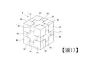
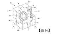
(第3變形例) 如圖13、14所示,液體容器4具備複數個第1構件41、複數個第2構件42、與複數個第3構件43。第1構件41是以第1接合部1101來取代第1實施形態的第1構件11(參照圖3)的第2接合部1102之構件。亦即,第1構件41是將一對第1接合部1101形成為側面視角下為L字形。 第3構件43是在第1實施形態的第3構件13(參照圖3)的開口部側之邊更形成第3突出部(圖示省略)。亦即,第3構件是從全周之邊突出有第3突出部。(3rd modified example) As shown in FIGS. 13 and 14 , the
液體容器4是將複數個第1構件41、數個第2構件42、複數個第3構件43與第1實施形態的各個構件11、12、13同樣地嵌合。像這樣,藉由嵌合複數個第1構件41、複數個第2構件42、複數個第3構件43,可將液體容器4形成為不具有開口部的全封閉狀態。亦即,根據液體容器4,可得到將第1實施形態的液體容器1的底部的相反側的開口封閉之組立式的液體容器。In the
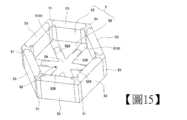
(第4變形例) 如圖15所示,液體容器5是將底部50形成為六角形,且將壁部55沿著底部50的外緣(周邊)形成為六角框。 液體容器5具備複數個第1構件51、第2構件52、複數個第3構件53。第1構件51是將第1實施形態的第1構件11當中,第2接合部1102(參照圖3)形成為平面視角下為V字形,其他的形狀則與第1構件11同樣。(4th modified example) As shown in FIG. 15 , in the
第2構件52是與第1實施形態的第2構件12(參照圖3)類似的構件。第2構件52是將第2凹突出部526從基座59間隔等間隔而放射狀地突出6個量。第1構件51的第1接合部5101以和第1實施形態同樣地對接的狀態來與第2凹突出部526嵌合。The
在相鄰的第1構件51與第1構件51之間配置第3構件53。第3構件53是將第1實施形態的第3構件13當中,第1平坦部1305(參照圖3)形成為平面視角下為三角形,其他的形狀則與第3構件13同樣。第3構件53是與第1實施形態同樣地與相鄰的第1構件51與第2構件52嵌合。The
(第5變形例) 如圖16、圖17所示,液體容器6是將底部60是形成為八角形,且將壁部65沿著底部60的外緣(周邊)而形成為八角框。液體容器6具備複數個第1構件61、第2構件62、複數個第3構件63、與複數個第4構件64。 第1構件61是將第1實施形態的第1構件11當中,第2接合部1102(參照圖3)形成為平面視角下為V字形,其他的形狀則與第1構件11同樣。(fifth modified example) As shown in FIGS. 16 and 17 , in the
第2構件62是設置在液體容器6的底部60的中央,且形成為平面視角下為八角形。複數個第4構件64與第2構件62的周邊嵌合。第1構件61以對接的狀態與第4構件64嵌合。在相鄰的第1構件61之間嵌合第3構件63。 可以藉由使第1構件61、第2構件62、第3構件63及第4構件64與第1實施形態的第1構件11、第2構件12、第3構件13同樣地嵌合,而形成組立式的液體容器。The
(第6變形例) 如圖18所示,液體容器7是將底部70形成為圓形,且將壁部75沿著底部70的外緣(周邊)而形成為圓筒。液體容器7具備複數個第1構件71、第2構件72、與第3構件73。 第1構件71是將第1實施形態的第1構件11當中,第2接合部1102(參照圖3)形成為平面視角下為曲面狀。(Sixth modified example) As shown in FIG. 18 , in the
第2構件72是設置於液體容器7的底部70的中央。將第1構件71於已對接的狀態來與第2構件72嵌合。在相鄰的第1構件71之間嵌合第3構件73。第3構件73是將第1實施形態的第3構件13當中,第2平坦部1306(參照圖3)形成為平面視角下為圓弧狀。 可以藉由將第1構件71、第2構件72、及第3構件73與第1實施形態的第1構件11、第2構件12、第3構件13同樣地嵌合,而形成組立式的液體容器。The
如以上所說明,根據第1實施形態、以及第1變形例~第6變形例的液體容器1、2、3、4、5、6、及7,可以將底部形成為多角形,且將壁部沿著底部的外緣(周邊)形成為多角框。藉此,可以對應於液體容器用途而選擇液體容器的形狀,且可謀求液體容器的用途的擴大。As described above, according to the
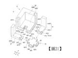
接著,根據圖19~圖27及圖28~圖34來分別說明第2實施形態及第3實施形態的液體容器8、9。 [第2實施形態] 如圖19,圖20所示,液體容器8是以形成為四邊形的底部80、與沿著底部80的外緣(周邊)形成為方框的壁部85所形成。此外,液體容器8是底部80的相反側形成開口。液體容器8是形成為以底部80與壁部85來將液體L收納於內部I。 具體而言,液體容器8是藉由複數個第1構件81、第2構件82、與複數個第3構件83所組裝而成。第2構件82是設置於底部80的中央。複數個第1構件81是與第2構件82嵌合。複數個第3構件83是與第2構件82及第1構件81嵌合。Next, the
如圖21所示,第1構件81具備第1接合部8101與第2接合部8102。第1接合部8101是形成液體容器8的底部80(參照圖19)的一部分。第2接合部8102是從第1接合部8101的外端部8101a朝液體容器8的深度方向延伸。第2接合部8102是形成壁部85的一部分。As shown in FIG. 21 , the
如圖22、圖23所示,第1接合部8101具有第1接合內表面8101c、第1接合外表面8101d、一對第1接合側面8101e。第1接合內表面8101c是配置於液體容器8的內部I側。第1接合外表面8101d是配置於液體容器8的外部O側。一對第1接合側面8101e的一邊是配置成將第1接合內表面8101c的一邊的側邊、與第1接合外表面8101d的一邊的側邊連結。一對第1接合側面8101e的另一邊是配置成將第1接合內表面8101c的另一邊的側邊、與第1接合外表面8101d的另一邊的側邊連結。 可藉第1接合內表面8101c、第1接合外表面8101d、及一對第1接合側面8101e將第1接合部8101形成為截面矩形狀。As shown in FIGS. 22 and 23 , the first
第1接合部8101是從液體容器8的壁部85(參照圖19)延伸到第2構件82。第1接合部8101是在液體容器8的中央側的端部(以下稱為內端部)8101b具有第1嵌合突出部8110。第1嵌合突出部8110具有第1突出部811及第2突出部812。 第1突出部811是形成為截面矩形狀,並且是在沿著液體容器8的底面(內表面)80a的方向上朝液體容器8的中央側突出。 第2突出部812是形成於第1突出部811當中液體容器8的底面80a側。第2突出部812是在沿著液體容器8的底面80a的方向上,朝液體容器8的中央側突出。The first joining
回到圖21,在第1接合部8101的第1嵌合突出部8110的外端部(相反側的端部)8101a形成有第2接合部8102。第2接合部8102是朝交叉於第1接合部8101的方向(亦即液體容器8的深度方向)延伸。第2接合部8102是與第1接合部8101同樣地形成為截面矩形狀。Returning to FIG. 21 , the second engaging
在底部80(參照圖19)的中央設置有第2構件82。第1接合部8101的第1嵌合突出部8110與第2構件82嵌合。第2構件82具有形成中央部的基座89、與形成在基座89的周圍的複數個第2嵌合凹部8210。 第2嵌合凹部8210是在基座89的外周形成有4個。亦即,第2嵌合凹部8210是從基座89的外周朝液體容器8的外部O在周方向上間隔等間隔而放射狀地突出。第2嵌合凹部8210具有與第1突出部811嵌合的第1凹部825、與形成於第1凹部825的第2凹部826。A
如圖22、圖23所示,第2嵌合凹部8210具有第1嵌合內表面8210a、第1嵌合外表面8210b、一對第1嵌合側面8210c。第1嵌合內表面8210a是配置於液體容器8的內部I側。第1嵌合外表面8210b是配置於液體容器8的外部O側。一對第1嵌合側面8210c的一邊是配置成將第1嵌合內表面8210a的一邊的側邊、與第1嵌合外表面8210b的一邊的側邊連結。一對第1嵌合側面8210c的另一邊是配置成將第1嵌合內表面8210a的另一邊的側邊、與第1嵌合外表面8210b的另一邊的側邊連結。 可藉第1嵌合內表面8210a、第1嵌合外表面8210b、及一對第1嵌合側面8210c將第2嵌合凹部8210的外形形成為截面矩形狀。As shown in FIGS. 22 and 23 , the second
第1凹部825是開口成與第1突出部811嵌合。第2凹部826是形成於第2嵌合凹部8210當中液體容器8的底面80a側的部位,並且形成為溝狀,以與第2突出部812嵌合。 可藉由第1突出部811與第1凹部825嵌合,而形成第1嵌合部801。可藉由第2突出部812與第2凹部826嵌合,而形成第2嵌合部802。 可藉由第1突出部811與第1凹部825嵌合,且第2突出部812與第2凹部826嵌合,而從第2構件82放射狀地延伸第1接合部8101。The first
如圖24所示,可將第1接合部8101的第1接合內表面8101c、與第2嵌合凹部8210的第1嵌合內表面8210a配置為齊平面。可將第1接合部8101的第1接合外表面8101d、與第2嵌合凹部8210的第1嵌合外表面8210b配置為齊平面。 第1突出部811具有一對第1突出面811a、811b。第1凹部825具有一對第1凹面825a、825b。可藉由第1突出部811與第1凹部825嵌合,而以一對第1突出面811a、811b的一邊的第1突出面811a、與一對第1凹面825a、825b的一邊的第1凹面825a而形成第1狹小部S7。可藉一對第1突出面811a、811b的另一邊的第1突出面811b、與一對第1凹面825a、825b的另一邊的第1凹面825b而形成第1狹小部S8。As shown in FIG. 24 , the first joint
亦即,第1嵌合部801具有一對第1狹小部S7、S8。一對第1狹小部S7、S8是將間隙形成為抑制液體容器8內的液體L的流出的空間。換言之,可將第1狹小部S7、S8設定為可以藉由表面張力來防止液體L滲入第1狹小部S7、S8之情形的間隙。 一對第1狹小部S7、S8是在第1構件81及第2構件82的嵌合方向(箭頭A方向)上、且從沿著液體容器8的底面(內表面)80a的方向觀看為交叉的方向(亦即液體容器8的深度方向)上形成間隙。That is, the first
回到圖22,第2突出部812具有一對第2突出側面812a、812b。第2凹部826具有一對第2凹側面826a、826b。可藉由第2突出部812與第2凹部826嵌合,而以一對第2突出側面812a、812b的一邊的第2突出側面812a、與一對第2凹側面826a、826b的一邊的第2凹側面826a形成第2狹小部S9。可藉一對第2突出側面812a、812b的另一邊的第2突出側面812b、與一對第2凹側面826a、826b的另一邊的第2凹側面826b形成第2狹小部S10。Returning to FIG. 22, the
亦即,第2嵌合部802具有一對第2狹小部S9、S10。第2狹小部S9、S10是將間隙形成為抑制液體容器8內的液體L的流出的空間。換言之,可將第2狹小部S9、S10設定為可以藉由表面張力來防止液體L滲入第1狹小部S7、S8之情形的間隙。第2狹小部S9、S10是在第1構件81及第2構件82的嵌合方向上、且沿著液體容器8的底面(內表面)80a的方向上形成間隙。That is, the second
如圖21所示,第3構件83具有第1平坦部8305與第2平坦部8306。第1平坦部8305是形成為平面視角下為矩形狀,且形成液體容器8的底部80(參照圖19)的一部分。第2平坦部8306是沿著第1平坦部8305的外緣(周邊)彎曲成平面視角下為L字形,且形成液體容器8的壁部85(參照圖19)的一部分。 此外,第3構件83具有與第1構件81及第2構件82嵌合的第3凹部833。第3凹部833具有形成於第1平坦部8305的第3底凹部837H、與形成於第2平坦部8306的第3壁凹部837V。As shown in FIG. 21 , the
第3底凹部837H是形成為可與第2構件82及第1構件81的第1接合部8101嵌合的截面凹狀。第3壁凹部837V是形成為可與第1構件81的第2接合部8102嵌合的截面凹狀。 具體而言,是第3構件83朝交叉於第1構件81及第2構件82的嵌合方向(箭頭A方向)的方向(箭頭B方向),與第1構件81及第2構件82當中側邊的第3突出部813、823對接並嵌合。 第3構件83是在複數個第1構件81已與第2構件82嵌合的狀態下,來與相鄰的第1構件81嵌合。The third bottom recessed
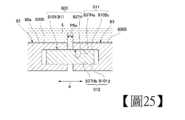
如圖24、圖25、圖26所示,第3底凹部837H是形成為截面凹狀,且具有第3底內凹面837Ha、與第3底外凹面837Hb。第3底內凹面837Ha及第3底外凹面837Hb是沿著液體容器8的底面80a而形成。 第3底凹部837H朝交叉於第1構件81及第2構件82的嵌合方向(箭頭A方向)的方向(箭頭B方向)與第1構件81的第1接合部8101嵌合。以第1接合部8101及第3底凹部837H形成第3嵌合部803。又,第3底凹部837H朝交叉於第1構件81及第2構件82的嵌合方向(箭頭A方向)的方向(箭頭B方向)與第2構件82嵌合。以第2構件82及第3底凹部837H形成第3嵌合部803。As shown in FIG. 24 , FIG. 25 , and FIG. 26 , the third bottom
可藉由第3底凹部837H與第1構件81的第1接合部8101嵌合,而藉由第3底內凹面837Ha與第1接合部8101的第1接合內表面8101c來形成第3狹小部S11。可藉由第3底外凹面837Hb與第1接合部8101的第1接合外表面8101d來形成第3狹小部S12。 又,可藉由第3底凹部837H與第2構件82嵌合,而藉由第3底內凹面837Ha與第1接合部8101的第1嵌合內表面8210a形成第3狹小部S11。可藉由第3底外凹面837Hb與第1接合部8101的第1嵌合外表面8210b,而形成第3狹小部S12。第3狹小部S11、S12是將間隙形成為抑制液體容器8內的液體L的流出的空間。第3狹小部S11、S12是在交叉於第1構件81及第2構件82的嵌合方向的方向、且沿著液體容器8的底面80a的方向觀看為交叉的方向(液體容器8的深度方向)上形成間隙。The third narrow portion S11 can be formed by fitting the third bottom
如圖20、圖21所示,可藉由第2平坦部8306的第3壁凹部837V與第1構件81的第2接合部8102嵌合,而形成第3狹小部S13及第3狹小部S14。第3狹小部S13是與第3狹小部S11(參照圖24)連續。第3狹小部S14是與第3狹小部S12(參照圖24)連續。 第3狹小部S13、S14是將間隙形成為抑制液體容器8內的液體L的流出的空間。換言之,可將第3狹小部S13、S14設定為可以藉由表面張力與接觸角的關係來防止液體L滲入第1狹小部S7、S8之情形的間隙。As shown in FIGS. 20 and 21 , the third narrow portion S13 and the third narrow portion S14 can be formed by fitting the third wall
如圖22、圖27所示,可藉由第1突出部811的第1突出面811a、與第1凹部825的第1凹面825a,於液體容器8的底面80a側形成第1狹小部S7。可藉由第2突出部812的第2突出側面812a、與第2凹部826的第2凹側面826a,於液體容器8的底面80a側形成第2狹小部S9。可藉由第2嵌合凹部8210的第1嵌合內表面8210a、與第3底凹部837H的第3底內凹面837Ha,於液體容器8的底面80a側形成第3狹小部S11。 使第2狹小部S9介於底面80a側的第1狹小部S7與底面80a側的第3狹小部S11之間,且藉由第2狹小部S9使底面80a側的第1狹小部S7與底面80a側的第3狹小部S11連續。22 and 27, the first narrow portion S7 can be formed on the
在將第1構件81與第2構件82對接,且例如產生了由地震所造成的變形或施工誤差的情況下,會在第1嵌合部801及第2嵌合部802形成空間P3、空間P4。又,在將相鄰的一邊的第3構件83的第1平坦部8305與另一邊的第3構件83的第1平坦部8305對接,且例如產生了由地震所造成的變形或施工誤差的情況下,會在已對接的第3構件83之間形成空間P5a。 此外,在將第1構件81與第3構件83對接,且例如產生了由地震所造成的變形或施工誤差的情況下,會形成空間P5b。又,在將第2構件82與第3構件83對接,且例如產生了由地震所造成的變形或施工誤差的情況下,會形成空間P5b。When the
然而,在第2實施形態中,空間P4不會透過空間P5b與液體容器8的外部O連通。又,在第2實施形態中,第2突出部812與第2凹部826的空間P3,不會與第1接合部8101的兩側的第1平坦部8305與8305之間的空間P5a連通。這是由於第2實施形態下了不使空間P3的液體L流入空間P4之工夫的緣故。 亦即,在第2實施形態中,形成了第1狹小部S7、第2狹小部S9及第3狹小部S11。據此,可以利用第1狹小部S7、第2狹小部S9及第3狹小部S11,來防止從空間P5a流入空間P3的液體L流入空間P4之情形。However, in the second embodiment, the space P4 does not communicate with the outside O of the
如圖20、圖21所示,藉由將複數個第1構件81、第2構件82、以及複數個第3構件83同樣地嵌合,可以容易地形成組立式的大的液體容器8。 具體而言,可將液體容器8組裝得很大,其中該液體容器8是底部80形成為在平面視角下為四邊形,且壁部85沿著底部80形成為方框的容器。As shown in FIGS. 20 and 21 , by similarly fitting a plurality of
只要以在第1構件81形成第1突出部811、第2突出部812,在第2構件82形成第1凹部825、第2凹部826,在第3構件83形成第3凹部833的簡單的構成,就可以形成組立式的大的液體容器8。 此外,可在第2構件82形成複數個第2嵌合凹部8210,且第1構件81與複數個第2嵌合凹部8210嵌合。據此,複數個第1構件81與一個第2構件82嵌合。可以將液體容器8的零件數量抑制得較少,而可謀求構成的簡單化。 藉由第3構件83與第1構件81及第2構件82嵌合,可形成例如液體容器8的底部80與壁部85。藉此,可以將液體容器8的零件數量進一步地抑制得較少,而可謀求構成的簡單化。As long as the first protruding
在第2實施形態的液體容器8中,雖然針對於第1構件81的第1接合部8101形成第1嵌合突出部8110,且於第2構件82形成第2嵌合凹部8210的例子作了說明,但並非限定於此。作為其他的例子,亦可將第2嵌合凹部8210形成於第1接合部8101,且將第1嵌合突出部8110形成於第2構件82。In the
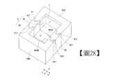
[第3實施形態] 如圖28,圖29所示,液體容器9是以形成為四邊形的底部90、與沿著底部90的外緣(周邊)形成為方框的壁部95所形成。此外,液體容器9是底部90的相反側形成開口。液體容器9是形成為以底部90與壁部95來將液體L收納於內部I。 具體而言,液體容器9是藉由第1構件91、第2構件92、與一對第3構件93A、93B所組裝而成。 將第1構件91與第2構件92的嵌合方向設為箭頭A方向,並將與箭頭A方向正交的方向設為箭頭B方向來進行說明。[third embodiment] As shown in FIGS. 28 and 29 , the
第1構件91是配置在液體容器9當中箭頭B方向的中央,且箭頭A方向的一側。第2構件92是配置在液體容器9當中箭頭B方向的中央,且箭頭A方向的另一側。第1構件91及第2構件92是形成為側面視角下為L字形。第1構件91的前端部911a與第2構件92的前端部922a嵌合。可於第1構件91及第2構件92的一邊的側部形成第3凹部917、927。可於第1構件91及第2構件92的另一邊的側部形成第3突出部913、923。 第3構件93A的第3突出部931與第3凹部917、927嵌合,且形成一邊的第3嵌合部903A。第3構件93B的第3凹部937與第3突出部913、923嵌合,且形成另一邊的第3嵌合部903B。The
如圖30、圖31、與圖32所示,第2構件92的第1凹部925與第1構件91的第1突出部911嵌合,且形成第1嵌合部901。可藉第1突出部911的一邊的突出部側面911a、與第1凹部925的一邊的凹側面925a形成第4狹小部S15。可藉第1突出部911的另一邊的突出部側面911b、與第1凹部925的另一邊的凹側面925b形成第4狹小部S16。 第4狹小部S15、S16是將間隙形成為抑制液體容器9內的液體L的流出的空間。As shown in FIG. 30 , FIG. 31 , and FIG. 32 , the first
第1構件91的第2突出部912與第2構件92的第2凹部926嵌合,且形成第2嵌合部902。可藉第2突出部912的突出部側面912a、與第2凹部926的凹側面926a形成第2狹小部S17。第2狹小部S17是將間隙形成為抑制液體容器9內的液體L的流出的空間。 又,可藉第3構件93B的第3凹部937的凹面937a、與第2構件92的另一側的突出面922形成第3狹小部S18。第3狹小部S18是將間隙形成為抑制液體容器9內的液體L的流出的空間。 此外,第1構件91的第4突出部914與第2構件92的第4凹部928嵌合,且形成第4嵌合部904。可藉第4凹部928的凹面928a、與第4突出部914的突出面914a形成第1狹小部S19。第1狹小部S19是將間隙形成為抑制液體容器9內的液體L的流出的空間。The
使第2狹小部S17介於第1狹小部S19與第3狹小部S18之間,且藉由第2狹小部S17使第1狹小部S19與第3狹小部S18連續。 據此,可以利用第1狹小部S19、第2狹小部S17及第3狹小部S18,來防止已流入空間P6的液體L經由空間P7而流入空間P8之情形。The 2nd narrow part S17 is interposed between the 1st narrow part S19 and the 3rd narrow part S18, and the 1st narrow part S19 and the 3rd narrow part S18 are continuous by the 2nd narrow part S17. Accordingly, the liquid L that has flowed into the space P6 can be prevented from flowing into the space P8 through the space P7 by using the first narrow portion S19 , the second narrow portion S17 , and the third narrow portion S18 .
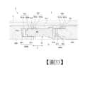
如圖32~圖34所示,一邊的第3嵌合部903A是第3突出部931與第3凹部917、927嵌合。可藉第3凹部917、927的凹面917a、927a、與第3突出部931的突出面931a形成一邊的第3狹小部S20。 一邊的第3狹小部S20是將間隙形成為抑制液體容器9內的液體L的流出的空間。據此,可以利用第3狹小部S20來防止已流入空間P9的液體L流入空間P10之情形。As shown in FIGS. 32 to 34 , in the third
另一邊的第3嵌合部903B是第3凹部937與第1構件91及第2構件92的第3突出部913、923嵌合。可藉第3凹部937的凹面937a與第3突出部913、923的突出面913a、923a,形成另一邊的第3狹小部S21。 另一邊的第3狹小部S21是將間隙形成為抑制液體容器9內的液體L的流出的空間。液體容器9是以第1構件91、第2構件92、及一對第3構件93A、93B來形成液體容器9的內側。據此,可以利用另一邊的第3狹小部S21來防止已流入空間P11的液體L流入空間P12之情形。In the third
藉此,如圖28~圖34所示,可以使第1構件91、第2構件92、及一對第3構件93A、93B嵌合,而容易地形成組立式的大的液體容器9。 具體而言,可將液體容器9組裝得很大,其中該液體容器9是底部90形成為在平面視角下為四邊形,且壁部95沿著底部90形成為方框的容器。Thereby, as shown in FIGS. 28 to 34 , the
本發明的液體容器可以在廣泛的領域中作為收納多種的液體的容器來使用。作為其較理想的例子,可以將液體容器作為玻璃製造用的熔融金屬槽來使用,其中該玻璃製造用的熔融金屬槽是收納用於以專利文獻WO2012/060197A等所揭示的浮式製法製造玻璃板等的玻璃物品之熔融的金屬等的液體。該浮式製法中的熔融金屬槽的內部蓄積有例如熔融金屬,具體而言為熔融錫,以作為液體L。 作為其他的例子,可以將液體容器作為用於製造玻璃物品之熔融玻璃的收納槽來使用。作為熔融玻璃的收納槽,也可以在用於對玻璃原料去除熔解後的熔融玻璃的氣泡的澄清槽、或用於對熔融玻璃進行下拉成形之稱為流槽(CANAL)、劍形物(SWORD)的成形用的裝置上利用。又,可以將在以往的玻璃製造設備上所使用之熔融金屬槽、流槽、及劍形物等替換為本發明的容器的構造,而利用於玻璃物品的製造方法上。 再者,作為形成本發明的液體容器的材料,是依所收納的液體的種類而有差異,通常所使用的是不會被所收納的液體腐蝕的材料。可使用例如不鏽鋼。又,例如作為耐火性為必要的材料,可使用碳、氮化硼等。The liquid container of the present invention can be used as a container for storing various liquids in a wide range of fields. As a more ideal example, the liquid container can be used as a molten metal tank for glass production, wherein the molten metal tank for glass production is a liquid containing molten metal or the like for producing glass articles such as glass plates by the float method disclosed in Patent Document WO2012/060197A and the like. For example, molten metal, specifically molten tin, is accumulated as liquid L in the molten metal tank in this float manufacturing method. As another example, the liquid container can be used as a storage tank for molten glass used to manufacture glassware. As a storage tank for molten glass, it can also be used in a clarification tank for removing air bubbles from molten glass from glass raw materials, or a forming device called launder (CANAL) or sword (SWORD) for down-draw forming molten glass. Also, the molten metal tank, launder, and sword used in conventional glass manufacturing equipment can be replaced with the structure of the container of the present invention, and can be used in the manufacturing method of glass articles. Furthermore, the material for forming the liquid container of the present invention varies depending on the type of liquid to be accommodated, but generally, a material that is not corroded by the liquid to be accommodated is used. Stainless steel can be used, for example. Also, for example, carbon, boron nitride, or the like can be used as a material that requires fire resistance.
再者,在此是引用已於2017年8月3日提申之日本專利申請案2017-150857號的說明書、專利申請範圍、圖式、及摘要的全部內容,並納入作為本發明的說明書之揭示。Furthermore, the entire content of the specification, scope of patent application, drawings, and abstract of Japanese Patent Application No. 2017-150857 filed on August 3, 2017 is cited here, and incorporated as the disclosure of the specification of the present invention.
1、2、3、4、5、6、7、8、9:液體容器 10、50、60、70、80、90、117c、125c:底部 10a、80a:底面(內表面) 101、801、901:第1嵌合部 102、802、902:第2嵌合部 103、803、903A、903B:第3嵌合部 11、21、31、41、51、61、71、81、91:第1構件 1101、5101、8101:第1接合部 1101a、8101a:外端部 1101b、8101b:內端部 1102、8102:第2接合部 111、811、911:第1突出部 111a、111b、811a、811b:第1突出面 111c、133c、911a、922a:前端部 1110、8110:第1嵌合突出部 116、826、926:第2凹部 116a、116b:第1凹側面 117、127、217、833、917、927、937:第3凹部 117a、117b、127a、127b:第3凹面 12、22、32、42、52、62、72、82、92:第2構件 1210、8210:第2嵌合凹部 122、812、912:第2突出部 122a、122b:突側面 125、825、925:第1凹部 125a、125b、825a、825b:第1凹面 13、23、33、43、53、63、73、83、93A、93B:第3構件 1305、8305:第1平坦部 1306、8306:第2平坦部 133、233、813、823、913、923、931:第3突出部 133a、133b:第3突出面 15、55、65、75、85、95:壁部 19、59、89:基座 34、64:第4構件 34a、34b、34c、34d:各邊 35:第5構件 35a、35b:部位 36:第6構件 526:第2凹突出部 8101c:第1接合內表面 8101d:第1接合外表面 8101e:第1接合側面 812a:第2突出側面 8210a:第1嵌合內表面 8210b:第1嵌合外表面 8210c:第1嵌合側面 826a、826b:第2凹側面 837V:第3壁凹部 837H:第3底凹部 837Ha:第3底內凹面 837Hb:第3底外凹面 904:第4嵌合部 911a、911b、912a:突出部側面 913a、914a、923a、931a、922:突出面 914:第4突出部 917a、927a、928a、937a:凹面 925a、925b、926a:凹側面 928:第4凹部 A、B:箭頭 H1:壁部高度 I:內部 L:液體 L1、L2:長度 O:外部 P1、P2、P3、P4、P5、P5a、P5b、P6、P7、P8、P9、P10、P11、P12:空間 S1、S2、S7、S8、S19:第1狹小部 S3、S4、S9、S10、S17:第2狹小部 S5、S6、S11、S12、S13、S14、S18、S20、S21:第3狹小部 S15、S16:第4狹小部 T1:板厚1, 2, 3, 4, 5, 6, 7, 8, 9: liquid container 10, 50, 60, 70, 80, 90, 117c, 125c: Bottom 10a, 80a: bottom surface (inner surface) 101, 801, 901: the first fitting part 102, 802, 902: the second fitting part 103, 803, 903A, 903B: the third fitting part 11, 21, 31, 41, 51, 61, 71, 81, 91: 1st member 1101, 5101, 8101: the first junction 1101a, 8101a: outer end 1101b, 8101b: inner end 1102, 8102: the second junction 111, 811, 911: the first protrusion 111a, 111b, 811a, 811b: first protruding surface 111c, 133c, 911a, 922a: front end 1110, 8110: 1st fitting protrusion 116, 826, 926: the second recess 116a, 116b: the first concave side 117, 127, 217, 833, 917, 927, 937: the third recess 117a, 117b, 127a, 127b: the third concave surface 12, 22, 32, 42, 52, 62, 72, 82, 92: 2nd member 1210, 8210: the second fitting recess 122, 812, 912: the second protrusion 122a, 122b: protruding side 125, 825, 925: the first recess 125a, 125b, 825a, 825b: the first concave surface 13, 23, 33, 43, 53, 63, 73, 83, 93A, 93B: 3rd member 1305, 8305: the first flat part 1306, 8306: the second flat part 133, 233, 813, 823, 913, 923, 931: the third protrusion 133a, 133b: the third protruding surface 15, 55, 65, 75, 85, 95: wall 19, 59, 89: base 34, 64: 4th component 34a, 34b, 34c, 34d: each side 35: 5th component 35a, 35b: parts 36: Component 6 526: Second concave protrusion 8101c: 1st joint inner surface 8101d: 1st joint outer surface 8101e: 1st joint side 812a: 2nd protruding side 8210a: 1st fitting inner surface 8210b: 1st fitting outer surface 8210c: 1st fitting side 826a, 826b: the second concave side 837V: 3rd wall recess 837H: 3rd bottom recess 837Ha: Concave surface of the third bottom 837Hb: Outer concave surface of the third bottom 904: 4th fitting part 911a, 911b, 912a: the side of the protrusion 913a, 914a, 923a, 931a, 922: protruding faces 914:4th protrusion 917a, 927a, 928a, 937a: concave surface 925a, 925b, 926a: concave side 928: 4th recess A, B: Arrows H1: Wall height I: internal L: liquid L1, L2: Length O: external P1, P2, P3, P4, P5, P5a, P5b, P6, P7, P8, P9, P10, P11, P12: space S1, S2, S7, S8, S19: the first narrow part S3, S4, S9, S10, S17: the second narrow part S5, S6, S11, S12, S13, S14, S18, S20, S21: the third narrow part S15, S16: The 4th narrow part T1: plate thickness
圖1是顯示本發明的液體容器之第1實施形態的立體圖。 圖2是顯示將第3構件的一部分從圖1的液體容器拆下的狀態的立體圖。 圖3是顯示已將圖2的液體容器分解的狀態的分解立體圖。 圖4是顯示圖3的液體容器的嵌合狀態的立體圖。 圖5是顯示已將圖4的第1構件與第2構件分解的狀態的分解立體圖。 圖6是顯示圖4的液體容器之沿著VI-VI線的截面圖。 圖7是顯示將圖4的液體容器的一部分破斷後的狀態的立體圖。 圖8是顯示圖4的液體容器之沿著IIX-IIX線的截面圖。 圖9是顯示圖4的液體容器之沿著IX-IX線的截面圖。 圖10是顯示圖4的液體容器之沿著X-X線的截面圖。 圖11是顯示本發明之第1實施形態的液體容器之第1變形例的立體圖。 圖12是顯示本發明之第1實施形態的液體容器之第2變形例的立體圖。 圖13是顯示本發明之第1實施形態的液體容器之第3變形例的立體圖。 圖14是顯示將一部分的構件從圖13的液體容器拆下的狀態的立體圖。 圖15是顯示本發明之第1實施形態的液體容器之第4變形例的立體圖。 圖16是顯示本發明之第1實施形態的液體容器之第5變形例的立體圖。 圖17是顯示將一部分的構件從圖16的液體容器拆下的狀態的立體圖。 圖18是顯示本發明之第1實施形態的液體容器之第6變形例的立體圖。 圖19是顯示本發明的液體容器之第2實施形態的立體圖。 圖20是顯示將第3構件的一部分從圖19的液體容器拆下的狀態的立體圖。 圖21是顯示已將圖20的液體容器分解的狀態的分解立體圖。 圖22是顯示圖21的液體容器的嵌合狀態的立體圖。 圖23是顯示已將圖22的第1構件與第2構件分解的狀態的分解立體圖。 圖24是顯示圖22的液體容器之沿著XXIV-XXIV線的截面圖。 圖25是顯示圖22的液體容器之沿著XXV-XXV線的截面圖。 圖26是顯示圖22的液體容器之沿著XXVI-XXVI線的截面圖。 圖27是顯示圖22的液體容器之沿著XXVII-XXVII線的截面圖。 圖28是顯示本發明的液體容器之第3實施形態的立體圖。 圖29是顯示將另一邊的第3構件的一部分從圖28的液體容器拆下的狀態的立體圖。 圖30是顯示已將圖29的液體容器分解的狀態的分解立體圖。 圖31是顯示圖30的液體容器的嵌合狀態的立體圖。 圖32是顯示圖31的液體容器之沿著XXXII-XXXII線的截面圖。 圖33是顯示圖31的液體容器之沿著XXXIII-XXXIII線的截面圖。 圖34是顯示圖31的液體容器之沿著XXXIV-XXXIV線的截面圖。Fig. 1 is a perspective view showing a first embodiment of the liquid container of the present invention. Fig. 2 is a perspective view showing a state where part of a third member is removed from the liquid container in Fig. 1 . Fig. 3 is an exploded perspective view showing a disassembled state of the liquid container of Fig. 2 . Fig. 4 is a perspective view showing a fitted state of the liquid container of Fig. 3 . Fig. 5 is an exploded perspective view showing a disassembled state of the first member and the second member of Fig. 4 . FIG. 6 is a sectional view showing the liquid container of FIG. 4 along line VI-VI. Fig. 7 is a perspective view showing a partially broken state of the liquid container of Fig. 4 . Fig. 8 is a sectional view showing the liquid container of Fig. 4 along line IIX-IIX. Fig. 9 is a sectional view showing the liquid container of Fig. 4 along line IX-IX. Fig. 10 is a sectional view showing the liquid container of Fig. 4 along line X-X. Fig. 11 is a perspective view showing a first modified example of the liquid container according to the first embodiment of the present invention. Fig. 12 is a perspective view showing a second modified example of the liquid container according to the first embodiment of the present invention. Fig. 13 is a perspective view showing a third modified example of the liquid container according to the first embodiment of the present invention. Fig. 14 is a perspective view showing a state in which some members are removed from the liquid container of Fig. 13 . Fig. 15 is a perspective view showing a fourth modification of the liquid container according to the first embodiment of the present invention. Fig. 16 is a perspective view showing a fifth modification of the liquid container according to the first embodiment of the present invention. Fig. 17 is a perspective view showing a state in which some members are removed from the liquid container of Fig. 16 . Fig. 18 is a perspective view showing a sixth modification of the liquid container according to the first embodiment of the present invention. Fig. 19 is a perspective view showing a second embodiment of the liquid container of the present invention. Fig. 20 is a perspective view showing a state where part of the third member is removed from the liquid container of Fig. 19 . Fig. 21 is an exploded perspective view showing a disassembled state of the liquid container of Fig. 20 . Fig. 22 is a perspective view showing a fitted state of the liquid container of Fig. 21 . Fig. 23 is an exploded perspective view showing a state in which the first member and the second member of Fig. 22 are disassembled. Fig. 24 is a sectional view showing the liquid container of Fig. 22 along line XXIV-XXIV. Fig. 25 is a sectional view showing the liquid container of Fig. 22 along line XXV-XXV. Fig. 26 is a sectional view showing the liquid container of Fig. 22 along line XXVI-XXVI. Fig. 27 is a sectional view showing the liquid container of Fig. 22 along line XXVII-XXVII. Fig. 28 is a perspective view showing a third embodiment of the liquid container of the present invention. Fig. 29 is a perspective view showing a state where part of the third member on the other side is removed from the liquid container in Fig. 28 . Fig. 30 is an exploded perspective view showing a disassembled state of the liquid container of Fig. 29 . Fig. 31 is a perspective view showing a fitted state of the liquid container of Fig. 30 . Fig. 32 is a sectional view showing the liquid container of Fig. 31 along line XXXII-XXXII. Fig. 33 is a sectional view showing the liquid container of Fig. 31 along the line XXXIII-XXXIII. Fig. 34 is a cross-sectional view showing the liquid container of Fig. 31 along line XXXIV-XXXIV.
1:液體容器1: Liquid container
11:第1構件11: 1st component
1101:第1接合部1101: the first junction
1101a:外端部1101a: outer end
1102:第2接合部1102: the second junction
111:第1突出部111: 1st protrusion
1110:第1嵌合突出部1110: 1st fitting protrusion
116:第2凹部116: 2nd concave part
117:第3凹部117: 3rd concave part
12:第2構件12: 2nd component
1210:第2嵌合凹部1210: the second fitting recess
122:第2突出部122: 2nd protrusion
125:第1凹部125: 1st concave part
127:第3凹部127: 3rd concave part
13:第3構件13: 3rd component
1305:第1平坦部1305: 1st flat part
1306:第2平坦部1306: The second flat part
133:第3突出部133: 3rd protrusion
A、B:箭頭A, B: Arrows
Claims (14)
Translated fromChineseApplications Claiming Priority (2)
| Application Number | Priority Date | Filing Date | Title |
|---|---|---|---|
| JP2017150857 | 2017-08-03 | ||
| JP2017-150857 | 2017-08-03 |
Publications (2)
| Publication Number | Publication Date |
|---|---|
| TW202246134A TW202246134A (en) | 2022-12-01 |
| TWI807964Btrue TWI807964B (en) | 2023-07-01 |
Family
ID=65232560
Family Applications (2)
| Application Number | Title | Priority Date | Filing Date |
|---|---|---|---|
| TW111130747ATWI807964B (en) | 2017-08-03 | 2018-08-02 | Method for manufacturing liquid container and glass article |
| TW107126876ATWI772481B (en) | 2017-08-03 | 2018-08-02 | container for liquid |
Family Applications After (1)
| Application Number | Title | Priority Date | Filing Date |
|---|---|---|---|
| TW107126876ATWI772481B (en) | 2017-08-03 | 2018-08-02 | container for liquid |
Country Status (6)
| Country | Link |
|---|---|
| US (1) | US11702243B2 (en) |
| EP (2) | EP3663234B1 (en) |
| JP (2) | JP6888680B2 (en) |
| CN (2) | CN110997524B (en) |
| TW (2) | TWI807964B (en) |
| WO (1) | WO2019026852A1 (en) |
Families Citing this family (1)
| Publication number | Priority date | Publication date | Assignee | Title |
|---|---|---|---|---|
| US11851357B2 (en)* | 2021-09-09 | 2023-12-26 | James William Masten, JR. | Method for forming shaped glass |
Citations (8)
| Publication number | Priority date | Publication date | Assignee | Title |
|---|---|---|---|---|
| JP2002314221A (en)* | 2001-04-16 | 2002-10-25 | Tokyo Kakoki Kk | Processing chamber and manufacturing method thereof |
| JP2004268989A (en)* | 2003-03-10 | 2004-09-30 | Fujikowa Industry Co Ltd | Foldable transport container |
| CN1829630A (en)* | 2003-08-01 | 2006-09-06 | Gea布克阀门股份有限公司 | Coupling closures and docking devices containing said coupling closures |
| CN100402393C (en)* | 2003-10-09 | 2008-07-16 | 旭硝子株式会社 | Glass plate packing case |
| CN203512373U (en)* | 2013-09-18 | 2014-04-02 | 京东方科技集团股份有限公司 | Packaging box |
| WO2014125878A1 (en)* | 2013-02-13 | 2014-08-21 | 株式会社カネカ | Constant temperature storage/transport container, and transport method |
| TW201437157A (en)* | 2013-01-17 | 2014-10-01 | Asahi Glass Co Ltd | Method for manufacturing molded body and method for manufacturing glass molded body |
| WO2015177407A1 (en)* | 2014-05-20 | 2015-11-26 | Outotec (Finland) Oy | A fluid holding tank |
Family Cites Families (42)
| Publication number | Priority date | Publication date | Assignee | Title |
|---|---|---|---|---|
| FR1270366A (en)* | 1960-10-14 | 1961-08-25 | Prefabricated structure and elements for its construction | |
| FR1357788A (en)* | 1963-02-28 | 1964-04-10 | Anciens Etablissements Sadon | Large capacity tank for corrosive products |
| JPS493797Y1 (en)* | 1969-08-29 | 1974-01-30 | ||
| JPS519941A (en)* | 1974-07-15 | 1976-01-27 | Toshiba Machine Co Ltd | Shihenni ototsunoarumenzai |
| US4244486A (en)* | 1979-05-11 | 1981-01-13 | Ewald Jr Herbert J | Tank |
| JPS58143319U (en)* | 1982-03-19 | 1983-09-27 | 株式会社昭和丸筒 | Assembly type exterior body |
| CA1246890A (en)* | 1988-03-10 | 1988-12-20 | Paul J. Kruger | Composite panel, wall assembly and components therefor |
| US5155872A (en)* | 1990-10-25 | 1992-10-20 | Aymes Doniel G | Swimming pool with interlocking wall panels and liner-receiving top rail |
| US6902061B1 (en)* | 2000-09-29 | 2005-06-07 | Paul Elstone | Collapsible liquid box |
| DE10133471B4 (en)* | 2001-07-10 | 2004-09-30 | Schott Glas | Trough for holding a melting bath made of glass or glass ceramic |
| FR2830850B1 (en)* | 2001-10-15 | 2003-12-26 | Glaverbel | SPACER RIDER HOLDER |
| CN1462713A (en)* | 2002-05-28 | 2003-12-24 | 岐阜塑料工业株式会社 | Assembling vessel |
| NZ544134A (en)* | 2003-07-07 | 2009-01-31 | Rodney M Derifield | Insulated shipping containers |
| US7360784B2 (en)* | 2004-02-13 | 2008-04-22 | Ultimate Survival Technologies, Llc | Multifunctional mobile storage and delivery system |
| JP2005329994A (en)* | 2004-05-21 | 2005-12-02 | Daiwa Kasei Ind Co Ltd | Built-up type housing box |
| NO20042678D0 (en)* | 2004-06-25 | 2004-06-25 | Det Norske Veritas As | Tank for storage of fluids at low temperatures, support means for a tank, sandwich structure for use in a tank and method for manufacturing a tank |
| KR100625119B1 (en)* | 2005-03-29 | 2006-09-20 | 주식회사 시온테크닉스 | Prefab Round Water Tank |
| US7708160B2 (en)* | 2006-01-10 | 2010-05-04 | United States Postal Service | Collapsible container |
| US7703632B2 (en)* | 2006-08-04 | 2010-04-27 | Kochanowski George E | Stackable and collapsible container |
| JP3128241U (en)* | 2006-10-20 | 2006-12-28 | 西武造園株式会社 | Assembled structure |
| US7896184B2 (en)* | 2007-11-26 | 2011-03-01 | Rehrig Pacific Company | Crate with collapsible wall |
| US20090302046A1 (en)* | 2008-06-10 | 2009-12-10 | You Crate Llc | Collapsible Containers |
| WO2010014115A2 (en)* | 2008-07-31 | 2010-02-04 | F3 & I2, Llc | Modular panels for enclosures |
| JP2010215239A (en) | 2009-03-13 | 2010-09-30 | Rihei Suzuki | Assembling type container |
| DE102009033502B4 (en)* | 2009-07-15 | 2016-03-03 | Schott Ag | Method and device for producing glass products from a molten glass |
| AU2009227869A1 (en)* | 2009-10-19 | 2011-05-12 | K. Hartwall Oy Ab | Collapsible Crate for Transportation and Display of Pieces, and Method for Supplying and Merchandising Products |
| EP2390199B1 (en)* | 2010-05-27 | 2013-07-10 | Rehrig Pacific Company | Collapsible dual height stacking container |
| JP5591640B2 (en)* | 2010-09-17 | 2014-09-17 | AzエレクトロニックマテリアルズIp株式会社 | Liquid container and assembly method |
| JP5704362B2 (en) | 2010-11-04 | 2015-04-22 | 旭硝子株式会社 | Float plate glass manufacturing method and float plate glass manufacturing apparatus |
| JPWO2012099073A1 (en)* | 2011-01-20 | 2014-06-30 | 旭硝子株式会社 | Glass roll, glass roll manufacturing apparatus, and glass roll manufacturing method |
| JP5049411B1 (en)* | 2011-06-12 | 2012-10-17 | 株式会社テクノミズホ | Assembly set of assembling-type planting container and assembling-type planting container |
| JP5145485B1 (en)* | 2011-08-10 | 2013-02-20 | 東京機材工業株式会社 | Side wall unit and manufacturing method thereof, and liquid storage tank provided with the side wall unit |
| CN202246389U (en)* | 2011-08-23 | 2012-05-30 | 信义节能玻璃(芜湖)有限公司 | Tin bath and top cover structure thereof |
| US9555959B1 (en)* | 2013-08-31 | 2017-01-31 | Dustin Ziegs | Modular fluid storage tank |
| US20150353232A1 (en)* | 2014-06-06 | 2015-12-10 | Edward Kandel | Size-adjustable receptacle |
| CN105197344A (en)* | 2014-06-25 | 2015-12-30 | 艾尔戴克斯国际公司 | Load bearing structure |
| JP3198009U (en)* | 2015-03-31 | 2015-06-11 | 積水化成品工業株式会社 | Packing material and package |
| JP2017150857A (en) | 2016-02-22 | 2017-08-31 | 株式会社キーエンス | Safety scanner |
| CN105691821B (en)* | 2016-03-29 | 2017-12-05 | 福建省农业科学院生物技术研究所 | Splicing construction and splicing casing |
| CN106005777A (en)* | 2016-06-28 | 2016-10-12 | 天津天纺高新物流有限公司 | Spliced logistics box with variable volumetric quantity |
| CN206202902U (en)* | 2016-11-25 | 2017-05-31 | 东南大学 | A kind of composable multi-functional receiver |
| CN206427461U (en)* | 2016-12-22 | 2017-08-22 | 浙江鄂石物流科技有限公司 | A kind of combinable body feed tank |
- 2018
- 2018-07-30CNCN201880050376.XApatent/CN110997524B/enactiveActive
- 2018-07-30JPJP2019534506Apatent/JP6888680B2/enactiveActive
- 2018-07-30CNCN202111056048.0Apatent/CN113734642B/enactiveActive
- 2018-07-30EPEP18840611.0Apatent/EP3663234B1/enactiveActive
- 2018-07-30WOPCT/JP2018/028485patent/WO2019026852A1/ennot_activeCeased
- 2018-07-30EPEP22160688.2Apatent/EP4043364B1/enactiveActive
- 2018-08-02TWTW111130747Apatent/TWI807964B/enactive
- 2018-08-02TWTW107126876Apatent/TWI772481B/enactive
- 2020
- 2020-01-30USUS16/776,594patent/US11702243B2/enactiveActive
- 2021
- 2021-02-01JPJP2021014670Apatent/JP7070726B2/enactiveActive
Patent Citations (8)
| Publication number | Priority date | Publication date | Assignee | Title |
|---|---|---|---|---|
| JP2002314221A (en)* | 2001-04-16 | 2002-10-25 | Tokyo Kakoki Kk | Processing chamber and manufacturing method thereof |
| JP2004268989A (en)* | 2003-03-10 | 2004-09-30 | Fujikowa Industry Co Ltd | Foldable transport container |
| CN1829630A (en)* | 2003-08-01 | 2006-09-06 | Gea布克阀门股份有限公司 | Coupling closures and docking devices containing said coupling closures |
| CN100402393C (en)* | 2003-10-09 | 2008-07-16 | 旭硝子株式会社 | Glass plate packing case |
| TW201437157A (en)* | 2013-01-17 | 2014-10-01 | Asahi Glass Co Ltd | Method for manufacturing molded body and method for manufacturing glass molded body |
| WO2014125878A1 (en)* | 2013-02-13 | 2014-08-21 | 株式会社カネカ | Constant temperature storage/transport container, and transport method |
| CN203512373U (en)* | 2013-09-18 | 2014-04-02 | 京东方科技集团股份有限公司 | Packaging box |
| WO2015177407A1 (en)* | 2014-05-20 | 2015-11-26 | Outotec (Finland) Oy | A fluid holding tank |
Also Published As
| Publication number | Publication date |
|---|---|
| TW201910217A (en) | 2019-03-16 |
| JP2021062925A (en) | 2021-04-22 |
| CN110997524B (en) | 2022-01-11 |
| CN113734642A (en) | 2021-12-03 |
| US20200165028A1 (en) | 2020-05-28 |
| CN113734642B (en) | 2023-02-28 |
| JPWO2019026852A1 (en) | 2020-07-30 |
| TWI772481B (en) | 2022-08-01 |
| JP7070726B2 (en) | 2022-05-18 |
| WO2019026852A1 (en) | 2019-02-07 |
| JP6888680B2 (en) | 2021-06-16 |
| EP3663234A4 (en) | 2021-06-30 |
| EP4043364A3 (en) | 2022-10-19 |
| EP3663234A1 (en) | 2020-06-10 |
| TW202246134A (en) | 2022-12-01 |
| EP3663234B1 (en) | 2023-12-06 |
| EP4043364A2 (en) | 2022-08-17 |
| CN110997524A (en) | 2020-04-10 |
| EP4043364B1 (en) | 2024-09-04 |
| US11702243B2 (en) | 2023-07-18 |
Similar Documents
| Publication | Publication Date | Title |
|---|---|---|
| RU2537284C2 (en) | Plastic pallet | |
| AU771441B2 (en) | Stacked static mixing elements | |
| TWI807964B (en) | Method for manufacturing liquid container and glass article | |
| CN103026164A (en) | Heat exchanger plate, plate heat exchanger provided therewith, and method for manufacturing a plate heat exchanger | |
| CN102597600B (en) | Polygon tanks for liquid natural gas | |
| US9927184B2 (en) | Heat exchanger | |
| WO2016090731A1 (en) | A pallet | |
| JP4877545B2 (en) | Concrete block body for rainwater storage and penetration facilities, and rainwater storage and penetration facilities using the same | |
| JP5682962B2 (en) | Upper lid | |
| JP6390107B2 (en) | Damping device and damping method for damping sloshing | |
| CN103660917A (en) | Radiator tank for radiator | |
| JP2008174270A (en) | Returnable box | |
| US20200377289A1 (en) | Packaging member for cleaning blades | |
| JP2022139645A (en) | Structural members and structural units | |
| CN220263508U (en) | High-strength anti-deformation corrugated case | |
| JPH05264192A (en) | Plate type heat exchanger | |
| CN218440358U (en) | Non-metal elastic structure | |
| JP2021092333A (en) | Plate type heat exchanger | |
| JP2025074839A (en) | Rainwater storage materials | |
| JP2021076293A (en) | Flange structure of lamination-type heat exchanger | |
| TWI632096B (en) | Package and cushion structure | |
| JP2025049790A (en) | Vibration isolation device | |
| JP3171032U (en) | Packing material | |
| EP2845712A1 (en) | Devices for diverting fluid channels | |
| TW201829951A (en) | Pressure container |